· 2015-02-07 · Title: Microsoft Word - padrao_Sbai_2013_versao_revisao.docx
7
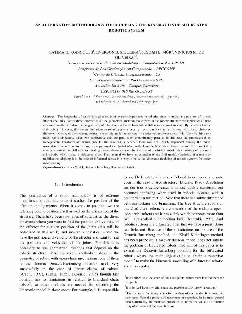
AN ALTERNATIVE METHODOLOGY FOR MODELING THE KINEMACTIS OF BIFURCATED ROBOTIC SYSTEM FÁTIMA H. RODRIGUES 1 , EVERSON B. SIQUEIRA 2 , JUSOAN L. MÓR 2 , VINÍCIUS M. DE OLIVEIRA 2,3 . 1 Programa de Pós-Graduação em Modelagem Computacional – PPGMC Programa de Pós-Graduação em Computação – PPGCOMP 2 Centro de Ciências Computacionais – C3 Universidade Federal do Rio Grande – FURG Av. Itália, km 8 s/n – Campus Carreiros CEP: 96217-010 Rio Grande RS Emails: {fatima.hernandes, eversonbrum, jmor, vinicius.oliveira}@furg.br Abstract—The kinematics of an articulated robot is of extreme importance in robotics since it studies the position of its end effector and links. For the direct kinematics is used geometrical methods that depend on the robotic structure for applications. There are several methods to describe the geometry of robots, one is the well-stablished D-H notation, used successfully in cases of serial chain robots. However, this has its limitations as robotic systems become more complex (that is the case with closed chains or bifurcated). One such disadvantage relates to take this model parameters with reference to the previous link. Likewise this same model has a singularity when two consecutive axis are parallel or approximately parallel. In this case the parameters di of homogeneous transformation which provides the relationship between these axis are linearly dependent making the model incomplete. Due to these limitations, it was proposed the Sheth-Uicker method and the Khalil-Kleinfinger method. The aim of this paper is to extend the D-H notation creating a new reference system for the case of brachiation robot, this consisting of two arms and a body, which makes a bifurcated robot. Then as goal we have an extension of the D-H model, consisting of a recursive modification adapting it to the case of bifurcated robots in a way to make the kinematic modeling of robotic systems for easier understanding. Keywords—Kinematics Model, Devanit-Hartenberg,Brachiation Robot. 1. Introduction The kinematics of a robot manipulator is of extreme importance in robotics, since it studies the position of the effector and ligaments. When it comes to position, we are referring both to position itself as well as the orientation of the structure. There have been two types of kinematics, the direct kinematic where you want to find the position and velocity of the effector for a given position of the joints (this will be addressed in this work) and inverse kinematics, where we have the position and velocity of the effector and want to find the positions and velocities of the joints. For this it is necessary to use geometrical methods that depend on the robotic structure. There are several methods to describe the geometry of robots with open-chain mechanisms, one of them is the famous Denavit-Hartenberg notation used very successfully in the case of linear chains of robots 1 (Aracil, 1997), (Craig, 1955), (Rosário, 2005) though this notation has its limitations in relation to branched chain robots 2 , so other methods are needed for obtaining the kinematic model in these cases. For example, it is impossible to use D-H notation in case of closed loop robots, and note even in the case of tree structure (Etienne, 1986). A solution for the tree structure cases is to use double subscripts but becomes confusing when used in robotic systems with n branches or n bifurcation. Note that there is a subtle difference between forking and branching. The tree structure robots or branched chain robots is a connection of the multiple open- loop serial robots and it has a link which connects more than two links (called a connection link) (Kanzaki, 1991). And robotic systems are bifurcated ones that we have a joint where two links out. Because of these limitations on the use of the Denavit-Hartenberg method, the Khalil-Kleinfinger method has been proposed. However the K-K model does not satisfy the problem of bifurcated robots. The aim of this paper is to extend the Denavit-Hartenberg notation for the bifurcated robots, where the main objective is to obtain a recursive model 3 to make the kinematic modelling of bifurcated robotic systems simpler. 1 It is defined as a sequence of links and joints, where there is a link between two joints. 2 It is derived from the serial chain and presents a structure with various. 3 The recursive functions, which form a class of computable functions, take their name from the process of recurrence or recursion. In its most general form numerically the recursion process is to define the value of a function using other values of the same function.
Transcript of · 2015-02-07 · Title: Microsoft Word - padrao_Sbai_2013_versao_revisao.docx
AN ALTERNATIVE METHODOLOGY FOR MODELING THE KINEMACTIS OF BIFURCATED ROBOTIC SYSTEM
FÁTIMA H. RODRIGUES1, EVERSON B. SIQUEIRA2, JUSOAN L. MÓR2, VINÍCIUS M. DE OLIVEIRA2,3.
1Programa de Pós-Graduação em Modelagem Computacional – PPGMC Programa de Pós-Graduação em Computação – PPGCOMP
2Centro de Ciências Computacionais – C3 Universidade Federal do Rio Grande – FURG
Av. Itália, km 8 s/n – Campus Carreiros CEP: 96217-010 Rio Grande RS
Emails: {fatima.hernandes, eversonbrum, jmor, vinicius.oliveira}@furg.br
Abstract—The kinematics of an articulated robot is of extreme importance in robotics since it studies the position of its end effector and links. For the direct kinematics is used geometrical methods that depend on the robotic structure for applications. There are several methods to describe the geometry of robots, one is the well-stablished D-H notation, used successfully in cases of serial chain robots. However, this has its limitations as robotic systems become more complex (that is the case with closed chains or bifurcated). One such disadvantage relates to take this model parameters with reference to the previous link. Likewise this same model has a singularity when two consecutive axis are parallel or approximately parallel. In this case the parameters di of homogeneous transformation which provides the relationship between these axis are linearly dependent making the model incomplete. Due to these limitations, it was proposed the Sheth-Uicker method and the Khalil-Kleinfinger method. The aim of this paper is to extend the D-H notation creating a new reference system for the case of brachiation robot, this consisting of two arms and a body, which makes a bifurcated robot. Then as goal we have an extension of the D-H model, consisting of a recursive modification adapting it to the case of bifurcated robots in a way to make the kinematic modeling of robotic systems for easier understanding. Keywords—Kinematics Model, Devanit-Hartenberg,Brachiation Robot.
1. Introduction
The kinematics of a robot manipulator is of extreme importance in robotics, since it studies the position of the effector and ligaments. When it comes to position, we are referring both to position itself as well as the orientation of the structure. There have been two types of kinematics, the direct kinematic where you want to find the position and velocity of the effector for a given position of the joints (this will be addressed in this work) and inverse kinematics, where we have the position and velocity of the effector and want to find the positions and velocities of the joints. For this it is necessary to use geometrical methods that depend on the robotic structure. There are several methods to describe the geometry of robots with open-chain mechanisms, one of them is the famous Denavit-Hartenberg notation used very successfully in the case of linear chains of robots1
(Aracil, 1997), (Craig, 1955), (Rosário, 2005) though this notation has its limitations in relation to branched chain robots2, so other methods are needed for obtaining the kinematic model in these cases. For example, it is impossible
to use D-H notation in case of closed loop robots, and note even in the case of tree structure (Etienne, 1986). A solution for the tree structure cases is to use double subscripts but becomes confusing when used in robotic systems with n branches or n bifurcation. Note that there is a subtle difference between forking and branching. The tree structure robots or branched chain robots is a connection of the multiple open-loop serial robots and it has a link which connects more than two links (called a connection link) (Kanzaki, 1991). And robotic systems are bifurcated ones that we have a joint where two links out. Because of these limitations on the use of the Denavit-Hartenberg method, the Khalil-Kleinfinger method has been proposed. However the K-K model does not satisfy the problem of bifurcated robots. The aim of this paper is to extend the Denavit-Hartenberg notation for the bifurcated robots, where the main objective is to obtain a recursive model3 to make the kinematic modelling of bifurcated robotic systems simpler.
1It is defined as a sequence of links and joints, where there is a link between two joints. 2It is derived from the serial chain and presents a structure with various. 3The recursive functions, which form a class of computable functions, take their name from the process of recurrence or recursion. In its most general form numerically the recursion process is to define the value of a function using other values of the same function.
2 The Devanit-Hartenberg Notation
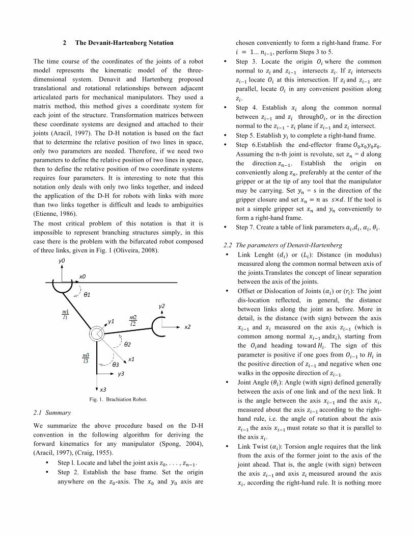
The time course of the coordinates of the joints of a robot model represents the kinematic model of the three-dimensional system. Denavit and Hartenberg proposed translational and rotational relationships between adjacent articulated parts for mechanical manipulators. They used a matrix method, this method gives a coordinate system for each joint of the structure. Transformation matrices between these coordinate systems are designed and attached to their joints (Aracil, 1997). The D-H notation is based on the fact that to determine the relative position of two lines in space, only two parameters are needed. Therefore, if we need two parameters to define the relative position of two lines in space, then to define the relative position of two coordinate systems requires four parameters. It is interesting to note that this notation only deals with only two links together, and indeed the application of the D-H for robots with links with more than two links together is difficult and leads to ambiguities (Etienne, 1986). The most critical problem of this notation is that it is impossible to represent branching structures simply, in this case there is the problem with the bifurcated robot composed of three links, given in Fig. 1 (Oliveira, 2008).
Fig. 1. Brachiation Robot.
2.1 Summary
We summarize the above procedure based on the D-H convention in the following algorithm for deriving the forward kinematics for any manipulator (Spong, 2004), (Aracil, 1997), (Craig, 1955).
• Step l. Locate and label the joint axis 𝑧!, . . . , 𝑧!!!. • Step 2. Establish the base frame. Set the origin
anywhere on the 𝑧!-axis. The 𝑥! and 𝑦! axis are
chosen conveniently to form a right-hand frame. For 𝑖 = 1... 𝑛!!!, perform Steps 3 to 5.
• Step 3. Locate the origin 𝑂! where the common normal to 𝑧! and 𝑧!!! intersects 𝑧!. If 𝑧! intersects 𝑧!!! locate 𝑂! at this intersection. If 𝑧! and 𝑧!!! are parallel, locate 𝑂! in any convenient position along 𝑧!.
• Step 4. Establish 𝑥! along the common normal between 𝑧!!! and 𝑧! through𝑂!, or in the direction normal to the 𝑧!!! - 𝑧! plane if 𝑧!!! and 𝑧! intersect.
• Step 5. Establish 𝑦! to complete a right-hand frame. • Step 6.Establish the end-effector frame 𝑂!𝑥!𝑦!𝑧!.
Assuming the n-th joint is revolute, set 𝑧! = d along the direction 𝑧!!!. Establish the origin on conveniently along 𝑧!, preferably at the center of the gripper or at the tip of any tool that the manipulator may be carrying. Set 𝑦! = s in the direction of the gripper closure and set 𝑥! = 𝑛 as 𝑠×𝑑. If the tool is not a simple gripper set 𝑥! and 𝑦! conveniently to form a right-hand frame.
• Step 7. Create a table of link parameters 𝑎!,𝑑!, 𝛼!, 𝜃!.
2.2 The parameters of Denavit-Hartenberg • Link Lenght (𝑑!) or (𝐿!): Distance (in modulus)
measured along the common normal between axis of the joints.Translates the concept of linear separation between the axis of the joints.
• Offset or Dislocation of Joints (𝛼!) or (𝑟!): The joint dis-location reflected, in general, the distance between links along the joint as before. More in detail, is the distance (with sign) between the axis 𝑥!!! and 𝑥! measured on the axis 𝑧!!! (which is common among normal 𝑥!!! and𝑥!), starting from the 𝑂!and heading toward 𝐻!. The sign of this parameter is positive if one goes from 𝑂!!! to 𝐻! in the positive direction of 𝑧!!! and negative when one walks in the opposite direction of 𝑧!!!.
• Joint Angle (𝜃!): Angle (with sign) defined generally between the axis of one link and of the next link. It is the angle between the axis 𝑥!!! and the axis 𝑥!, measured about the axis 𝑧!!! according to the right-hand rule, i.e. the angle of rotation about the axis 𝑧!!! the axis 𝑥!!! must rotate so that it is parallel to the axis 𝑥!.
• Link Twist (𝛼!): Torsion angle requires that the link from the axis of the former joint to the axis of the joint ahead. That is, the angle (with sign) between the axis 𝑧!!! and axis 𝑧! measured around the axis 𝑥!, according the right-hand rule. It is nothing more
than the angle of rotation around the axis 𝑥! the axis 𝑧!!! must turn to be parallel to the axis 𝑧! .
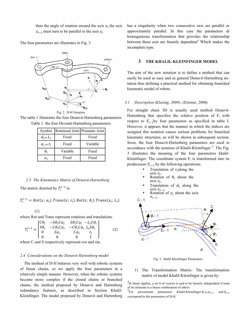
The four parameters are illustrates in Fig. 2
Fig. 2. D-H Notation.
The table 1 illustrates the four Denavit-Hartenberg parameters Table 1. the four Devanit-Hartenberg parameters.
Symbol Rotational Joint Prismatic Joint 𝑑!or 𝐿! Fixed Fixed 𝛼! or 𝑟! Fixed Variable 𝜃! Variable Fixed 𝛼! Fixed Fixed
2.3 The Kinematics Matrix of Denavit-Hartenberg
The matrix denoted by 𝑇!!!! is:
𝑇!!!! = 𝑅𝑜𝑡 𝑥; 𝛼! .𝑇𝑟𝑎𝑛𝑠 𝑧; 𝑟! .𝑅𝑜𝑡 𝑧; 𝜃! .𝑇𝑟𝑎𝑛𝑠 𝑥!; 𝐿! (1) where Rot and Trans represent rotations and translations.
𝑇!!!! =
𝐶𝜃! −𝑆𝜃!𝐶𝛼! 𝑆𝜃!𝐶𝛼! 𝑆𝜃! −𝐶𝜃!𝐶𝛼! −𝐶𝜃!𝐶𝛼!0 𝑆𝛼! 𝐶𝛼!0 0 0
−𝐿!𝐶𝜃!𝐿!𝑆𝜃!𝑟!1
(2)
where C and S respectively represent cos and sin.
2.4 Considerations on the Denavit-Hartenberg model The method of D-H behaves very well with robotic systems
of linear chains, so we apply the four parameters in a relatively simple manner. However, when the robotic systems become more complex if the closed chains or branched chains, the method proposed by Denavit and Hartenberg redundancy features, as described in Section Khalil-Kleinfinger. The model proposed by Denavit and Hartenberg
has a singularity when two consecutive axis are parallel or approximately parallel. In this case the parameters di homogeneous transformation that provides the relationship between these axis are linearly dependent4 Which makes the incomplete type.
3 THE KHALIL-KLEINFINGER MODEL
The aim of the new notation is to define a method that can easily be used as easy and as general Denavit-Hartenberg no-tation thus defining a practical method for obtaining branched kinematic model of robots.
3.1 Description (Klasing, 2009), (Etienne, 2006)
For straight chain 3D is usually used method Denavit-Hartenberg that specifies the relative position of Fi with respect to 𝐹!!!by four parameters as specified in table I. However, it appears that the manner in which the indices are assigned this notation causes serious problems for branched kinematic structures, as will be shown in subsequent section. Soon, the four Denavit-Hartenberg parameters are used in accordance with the notation of Khalil-Kleinfinger 5. The Fig. 3 illustrates the meaning of the four parameters khalil-Kleinfinger. The coordinate system Fi is transformed into its predecessor 𝐹!!! by the following operations:
• Translation of 𝑟!along the axis 𝑧!.
• Rotation of 𝜃! about the axis 𝑧!.
• Translation of 𝑑! along the axis 𝑥!!!.
• Rotation of 𝛾! about the axis 𝑥!!!.
Fig. 3. khalil-Kleinfinger Parameters.
1) The Transformation Matrix: The transformation
matrix of model Khalil-Kleinfinger is given by: 4In linear algebra, a set S of vectors is said to be linearly independent if none of its elements is a linear combination of others. 5For powertrains parameters Khalil-Kleinfinger 𝜃! ,𝑟! ,𝛼!!! and d!!! correspond to the parameters of D-H.
𝑇!!!! = 𝑇𝑟𝑎𝑛𝑠 𝑥,𝑑! .𝑅𝑜𝑡 𝑥,𝛼! .𝑇𝑟𝑎𝑛𝑠 𝑢, 𝑎!" .𝑅𝑜𝑡 𝑧, 𝜃! .𝑇𝑟𝑎𝑛𝑠 𝑧, 𝑟! (3)
𝑇!!!! =
𝐶𝜃! −𝑆𝜃! 0 𝑑!𝐶𝛼!𝑆𝜃! 𝐶𝜃!𝐶𝛼! −𝑆𝛼! −𝑟!𝑆𝛼!𝑆𝛼!𝑆𝜃! 𝑆𝛼!𝐶𝜃! 𝐶𝛼! 𝑟!𝐶𝛼!0 0 0 1
(4)
2) About the variable joints: A joint variable 𝑖 is denoted by 𝑞! is 𝜃! if 𝑖 is rotational and 𝑟! if 𝑖 is prismatic. Therefore, 𝑞! = 𝜃! 1 − 𝜎 + 𝑟!𝜎! where, 𝜎! = 0 if the joint i is rotational and 𝜎! = 1 if the joint 𝑖 is prismatic.
3.2 Robots branched chain in Khalil-Kleinfinger
Notation (Klasing, 2009), (Khalil, 2006)
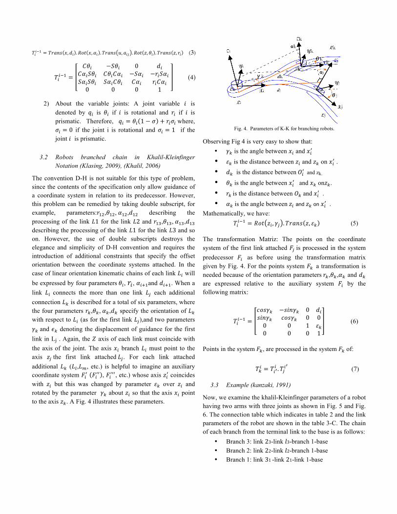
The convention D-H is not suitable for this type of problem, since the contents of the specification only allow guidance of a coordinate system in relation to its predecessor. However, this problem can be remedied by taking double subscript, for example, parameters:𝑟!",𝜃!", 𝛼!",𝑑!" describing the processing of the link 𝐿1 for the link 𝐿2 and 𝑟!",𝜃!", 𝛼!",𝑑!" describing the processing of the link 𝐿1 for the link 𝐿3 and so on. However, the use of double subscripts destroys the elegance and simplicity of D-H convention and requires the introduction of additional constraints that specify the offset orientation between the coordinate systems attached. In the case of linear orientation kinematic chains of each link 𝐿! will be expressed by four parameters 𝜃!, 𝑟! , 𝛼!!!and 𝑑!!!. When a link 𝐿! connects the more than one link 𝐿! each additional connection 𝐿! is described for a total of six parameters, where the four parameters 𝑟!,𝜃!, 𝛼!,𝑑! specify the orientation of 𝐿! with respect to 𝐿! (as for the first link 𝐿!),and two parameters 𝛾! and 𝜖! denoting the displacement of guidance for the first link in Lj . Again, the 𝑍 axis of each link must coincide with the axis of the joint. The axis 𝑥! branch 𝐿! must point to the axis 𝑧! the first link attached 𝐿!. For each link attached additional 𝐿! (𝐿!,𝐿!, etc.) is helpful to imagine an auxiliary coordinate system 𝐹!! 𝐹!!! , 𝐹!!!!, etc.) whose axis 𝑧!! coincides with 𝑧! but this was changed by parameter 𝜀! over 𝑧! and rotated by the parameter 𝛾! about 𝑧! so that the axis 𝑥! point to the axis 𝑧!. A Fig. 4 illustrates these parameters.
Fig. 4. Parameters of K-K for branching robots.
Observing Fig 4 is very easy to show that:
• 𝛾! is the angle between 𝑥! and 𝑥!! • 𝜀! is the distance between 𝑧! and 𝑧! on 𝑥!! . • 𝑑! is the distance between 𝑂!! and zk. • 𝜃! is the angle between 𝑥!! and 𝑥! on𝑧!. • 𝑟! is the distance between 𝑂! and 𝑥!! . • 𝛼! is the angle between 𝑧! and 𝑧! on 𝑥!! .
Mathematically, we have: 𝑇!!!! = 𝑅𝑜𝑡 𝑧! , 𝛾! . 𝑇𝑟𝑎𝑛𝑠 𝑧, 𝜀! (5)
The transformation Matriz: The points on the coordinate system of the first link attached 𝐹! is processed in the system predecessor 𝐹! as before using the transformation matrix given by Fig. 4. For the points system 𝐹! a transformation is needed because of the orientation parameters 𝑟!,𝜃!,𝛼! and 𝑑!
are expressed relative to the auxiliary system 𝐹! by the following matrix:
𝑇!!!! =
𝑐𝑜𝑠𝛾! −𝑠𝑖𝑛𝛾! 0 𝑑!𝑠𝑖𝑛𝛾! 𝑐𝑜𝑠𝛾! 0 00 0 1 𝜀!0 0 0 1
(6)
Points in the system 𝐹!, are processed in the system 𝐹! of:
𝑇!! = 𝑇!!! .𝑇!!
! (7)
3.3 Example (kanzaki, 1991)
Now, we examine the khalil-Kleinfinger parameters of a robot having two arms with three joints as shown in Fig. 5 and Fig. 6. The connection table which indicates in table 2 and the link parameters of the robot are shown in the table 3-C. The chain of each branch from the terminal link to the base is as follows:
• Branch 3: link 23-link 𝑙3-branch 1-base • Branch 2: link 22-link 𝑙2-branch 1-base • Branch 1: link 31 -link 21-link 1-base
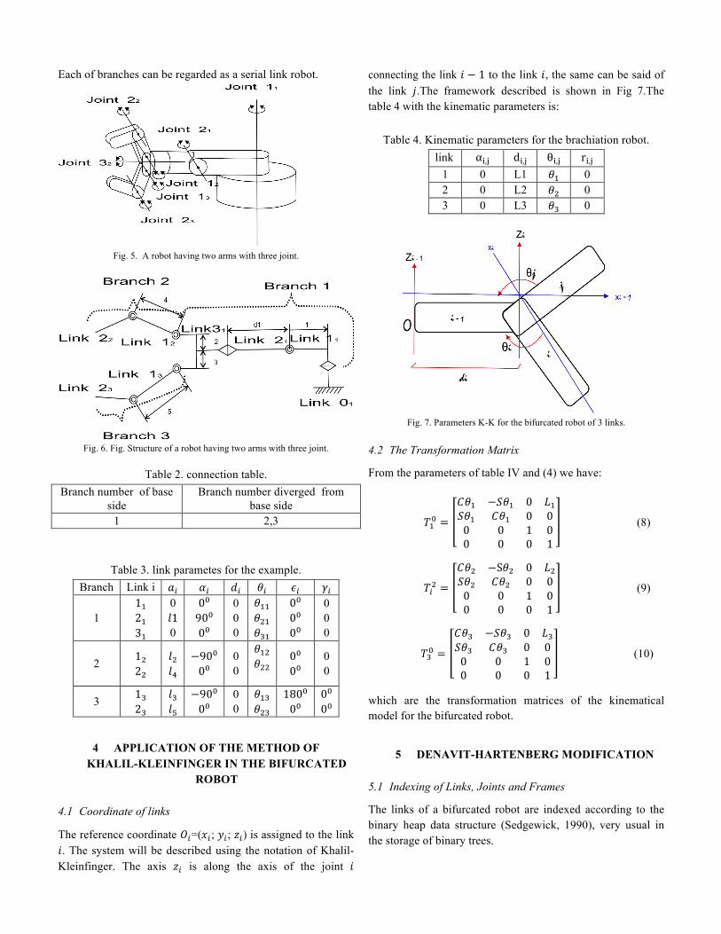
Each of branches can be regarded as a serial link robot.
Fig. 5. A robot having two arms with three joint.
Fig. 6. Fig. Structure of a robot having two arms with three joint.
Table 2. connection table. Branch number of base
side Branch number diverged from
base side 1 2,3
Table 3. link parametes for the example. Branch Link i 𝑎! 𝛼! 𝑑! 𝜃! 𝜖! 𝛾!
1 1! 2! 3!
0 𝑙1 0
0! 90! 0!
0 0 0
𝜃!! 𝜃!" 𝜃!"
0! 0! 0!
0 0 0
2 1! 2!
𝑙! 𝑙!
−90! 0!
0 0
𝜃!" 𝜃!!
0! 0!
0 0
3 1! 2!
𝑙! 𝑙!
−90! 0!
0 0
𝜃!" 𝜃!"
180! 0!
0! 0!
4 APPLICATION OF THE METHOD OF KHALIL-KLEINFINGER IN THE BIFURCATED
ROBOT
4.1 Coordinate of links
The reference coordinate 𝑂!=(𝑥!; 𝑦!; 𝑧!) is assigned to the link 𝑖. The system will be described using the notation of Khalil-Kleinfinger. The axis 𝑧! is along the axis of the joint 𝑖
connecting the link 𝑖 − 1 to the link 𝑖, the same can be said of the link 𝑗.The framework described is shown in Fig 7.The table 4 with the kinematic parameters is:
Table 4. Kinematic parameters for the brachiation robot. link α!,! d!,! θ!,! r!,!
1 0 L1 𝜃! 0 2 0 L2 𝜃! 0 3 0 L3 𝜃! 0
Fig. 7. Parameters K-K for the bifurcated robot of 3 links.
4.2 The Transformation Matrix
From the parameters of table IV and (4) we have:
𝑇!! =
𝐶𝜃! −𝑆𝜃! 0 𝐿!𝑆𝜃! 𝐶𝜃! 0 00 0 1 00 0 0 1
(8)
𝑇!! =
𝐶𝜃! −S𝜃! 0 𝐿!𝑆𝜃! 𝐶𝜃! 0 00 0 1 00 0 0 1
(9)
𝑇!! =
𝐶𝜃! −𝑆𝜃! 0 𝐿!𝑆𝜃! 𝐶𝜃! 0 00 0 1 00 0 0 1
(10)
which are the transformation matrices of the kinematical model for the bifurcated robot.
5 DENAVIT-HARTENBERG MODIFICATION
5.1 Indexing of Links, Joints and Frames
The links of a bifurcated robot are indexed according to the binary heap data structure (Sedgewick, 1990), very usual in the storage of binary trees.
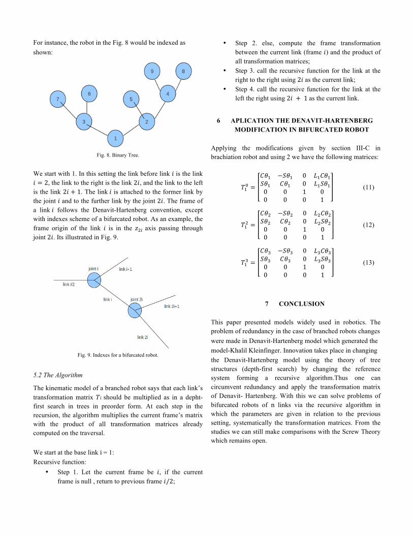
For instance, the robot in the Fig. 8 would be indexed as shown:
Fig. 8. Binary Tree.
We start with 1. In this setting the link before link 𝑖 is the link 𝑖 = 2, the link to the right is the link 2𝑖, and the link to the left is the link 2𝑖 + 1. The link 𝑖 is attached to the former link by the joint 𝑖 and to the further link by the joint 2𝑖. The frame of a link 𝑖 follows the Denavit-Hartenberg convention, except with indexes scheme of a bifurcated robot. As an example, the frame origin of the link 𝑖 is in the 𝑧!! axis passing through joint 2𝑖. Its illustrated in Fig. 9.
Fig. 9. Indexes for a bifurcated robot.
5.2 The Algorithm
The kinematic model of a branched robot says that each link’s transformation matrix 𝑇𝑖 should be multiplied as in a depht-first search in trees in preorder form. At each step in the recursion, the algorithm multiplies the current frame’s matrix with the product of all transformation matrices already computed on the traversal. We start at the base link i = 1: Recursive function:
• Step 1. Let the current frame be 𝑖, if the current frame is null , return to previous frame 𝑖/2;
• Step 2. else, compute the frame transformation between the current link (frame 𝑖) and the product of all transformation matrices;
• Step 3. call the recursive function for the link at the right to the right using 2𝑖 as the current link;
• Step 4. call the recursive function for the link at the left the right using 2𝑖 + 1 as the current link.
6 APLICATION THE DENAVIT-HARTENBERG MODIFICATION IN BIFURCATED ROBOT
Applying the modifications given by section III-C in brachiation robot and using 2 we have the following matrices:
𝑇!! =
𝐶𝜃! −𝑆𝜃! 0 𝑆𝜃! 𝐶𝜃! 0 0 0 10 0 0
𝐿!𝐶𝜃!𝐿!𝑆𝜃!01
(11)
𝑇!! =
𝐶𝜃! −𝑆𝜃! 0 𝑆𝜃! 𝐶𝜃! 0 0 0 10 0 0
𝐿!𝐶𝜃!𝐿!𝑆𝜃!01
(12)
𝑇!! =
𝐶𝜃! −𝑆𝜃! 0 𝑆𝜃! 𝐶𝜃! 0 0 0 10 0 0
𝐿!𝐶𝜃!𝐿!𝑆𝜃!01
(13)
7 CONCLUSION
This paper presented models widely used in robotics. The problem of redundancy in the case of branched robots changes were made in Denavit-Hartenberg model which generated the model-Khalil Kleinfinger. Innovation takes place in changing the Denavit-Hartenberg model using the theory of tree structures (depth-first search) by changing the reference system forming a recursive algorithm.Thus one can circumvent redundancy and apply the transformation matrix of Denavit- Hartenberg. With this we can solve problems of bifurcated robots of n links via the recursive algorithm in which the parameters are given in relation to the previous setting, systematically the transformation matrices. From the studies we can still make comparisons with the Screw Theory which remains open.
REFERENCES
Aracil, R.. and Barrientos, L. A. (1997). Fundamentos de Robótica, McGraw Hill.
Craig, J. (1955). Introduction to Robotics Mechanics and Control. Silma Inc.
Rosário, J. M. (2005). Princípios de Mecatrônica, Prentice Hall.
Khalil, W. and Kleinfinger, J. F. (1986). A new geometric notation for open and closed loop robots. IEEE.
Kanzaki, K and Kawasaki, B. H. and (1991). Minimum dynamics parameters of tree structure robot models. IEEE.
Oliveira, V. M. (2008). Estudo e controle de robôs bracejadores subatuados. Ph.D. thesis, Escola de Engenharia, Departamento de Engenharia Elétrica, Universidade Federal do Rio Grande do Sul.
Spong, M. W. and Vidvasagar, M. (2004). Robot Dynamics and Control.
Klasing, K. (2009). Parallelized sampling-based path planning for tree structured rigid robots, Master’s thesis, Institute of Automatic Control Engineering, Technische Universität München.
Etienne, D. and Khalil, W. and (2006). Identification, and Control of Robots,Butterworth-Heinemann.
Sedgewick, R. (1990). Algorithms in C (Fundamental Algorithms, Data Structures, Sorting, Searching), Addison-Wesley.


![K µ ] D v }Title: Microsoft Word - Novo_a_ Documento do Microsoft Office Word Author: Wallace Created Date: 3/10/2020 11:25:21 AM](https://static.fdocumentos.com/doc/165x107/5f60222921da751fb40e5d68/k-d-v-title-microsoft-word-novoa-documento-do-microsoft-office-word.jpg)