
A MULTI-CORE SOFTWARE DESIGN OF A MODEL … · processadores simultaneamente. Palavras-chave|...
7
A MULTI-CORE SOFTWARE DESIGN OF A MODEL PREDICTIVE CONTROL FOR A TILT-ROTOR UAV Gabriela M. T. Miranda * , Leandro M. F. Machado † , Janier Arias-Garcia † , Guilherme V. Raffo *† * Graduate Program in Electrical Engineering - Federal University of Minas Gerais Av. Antˆonio Carlos 6627, 31270-901 Belo Horizonte, MG, Brazil † Department of Electronic Engineering - Federal University of Minas Gerais Av. Antˆonio Carlos 6627, 31270-901 Belo Horizonte, MG, Brazil Emails: [email protected], [email protected], [email protected], [email protected] Abstract— This paper addresses the implementation of an embedded model predictive controller (MPC) designed to solve the path tracking problem of a tilt-rotor unmanned aerial vehicle (UAV). The architecture of the system is presented, describing its functional and non-functional features. The development of a dual-core software architecture for implementing an MPC is proposed, making use of the Robot Operating System (ROS) framework and the Gazebo simulator to obtain the numerical results. The software architecture approach is designed in order to improve the time MPC performance using the multiple processors simultaneously. Keywords— Software Architecture, Multi-core, MPC, Embedded Systems. Resumo— Este artigo aborda a implementa¸c˜ ao de um controlador preditivo (MPC) embarcado projetado para resolver o problema de rastreamento de trajet´ oria de um ve´ ıculo a´ ereo n˜ao tripulado (VANT) tilt-rotor. A arquitetura do sistema ´ e apresentada, descrevendo suas caracter´ ısticas funcionais e n˜ ao funcionais. O desenvol- vimento da arquitetura de software com dois n´ ucleos ´ e proposta para a implementa¸c˜ ao de um MPC, no qual ´ e usado o arcabou¸co Robot Operating System (ROS) e o simulador Gazebo para obter os resultados num´ ericos. A abordagem da arquitetura de software ´ e projetada para melhorar o tempo de execu¸c˜ ao do MPC usando m´ ultiplos processadores simultaneamente. Palavras-chave— Arquitetura de Software, M´ ultiplos N´ ucleos, Controle Preditivo, Sistemas Embarcados 1 Introduction Unmanned aerial vehicles (UAVs) have attracted enormous interest from the academic community and industry to many applications: Inspection of high voltage transmission line (Araar and Aouf, 2014); Measurements made by mapping reserves (Tariq et al., 2016); stockpiles, extracted mate- rials, mines and parks (Ge et al., 2016); Safety and Security by reconnaissance of the firegrounds (Belbachir et al., 2016) of accident and crime scene investigation, or to incorporate aerial assistance in search and rescue operations (Dhaliwal and Ramirez-Serrano, 2009), among others. This interest arises from the capability to fly autonomously or teleoperated as well as for appli- cations that offer risks to human life. In recent years, their use have being expanded in a broad and far-reaching applications, exploring mechan- ical and electronic advances that lead to tasks with more complex embedded mechatronics sys- tems (Vega et al., 2015). In that context, a hybrid type of UAV, known as tilt-rotor UAV, that com- bines the benefits of helicopter and airplane, gains special attention motivated by its capabilities of Vertical Take-Off and Landing (VTOL), and the superior flight autonomy of airplanes (Rego and Raffo, 2016). Some of the main issues involving the devel- opment process of Tilt-Rotor UAVs arise in de- signing the control strategy and mapping prop- erly its hardware/software architecture in the em- bedded system. As a suitable control strategy that produces optimal response accommodating constraints is the model predictive control (MPC) (Camacho, E. F.; Bordons, 2007). However, since its drawback is a computationally expensive algo- rithm, for systems with fast dynamics such as a tilt-rotor UAV, it must be implemented properly. Therefore, to control the tilt-rotor UAV by using an MPC algorithm, a complex embedded system must be designed in order to deal with dif- ferent system requirements, such as: performance, low-power consumption, area, precision, reliabil- ity, among others. Besides, the communication between sensors and actuators must be executed in such way to reduce the data path delay among the system levels. However, the challenge is to find a proper trade-off among the system requirements to improve parameters like performance, area, etc. Code parallelization could be used to improve the MPC algorithm performance by converting se- quential code into multithreaded code, taking ad- vantage of multi-core system architectures. The use of this kind of technique is growing up to dif- ferent applications, such as graph algorithms (Lu XIII Simp´osio Brasileiro de Automa¸ c˜ ao Inteligente Porto Alegre – RS, 1 o – 4 de Outubro de 2017 ISSN 2175 8905 2345
-
Upload
trinhkhanh -
Category
Documents
-
view
215 -
download
0
Transcript of A MULTI-CORE SOFTWARE DESIGN OF A MODEL … · processadores simultaneamente. Palavras-chave|...
A MULTI-CORE SOFTWARE DESIGN OF A MODEL PREDICTIVE CONTROL FORA TILT-ROTOR UAV
Gabriela M. T. Miranda∗, Leandro M. F. Machado†, Janier Arias-Garcia†, Guilherme V.Raffo∗†
∗Graduate Program in Electrical Engineering - Federal University of Minas GeraisAv. Antonio Carlos 6627, 31270-901
Belo Horizonte, MG, Brazil
†Department of Electronic Engineering - Federal University of Minas GeraisAv. Antonio Carlos 6627, 31270-901
Belo Horizonte, MG, Brazil
Emails: [email protected], [email protected], [email protected],
Abstract— This paper addresses the implementation of an embedded model predictive controller (MPC)designed to solve the path tracking problem of a tilt-rotor unmanned aerial vehicle (UAV). The architecture ofthe system is presented, describing its functional and non-functional features. The development of a dual-coresoftware architecture for implementing an MPC is proposed, making use of the Robot Operating System (ROS)framework and the Gazebo simulator to obtain the numerical results. The software architecture approach isdesigned in order to improve the time MPC performance using the multiple processors simultaneously.
Keywords— Software Architecture, Multi-core, MPC, Embedded Systems.
Resumo— Este artigo aborda a implementacao de um controlador preditivo (MPC) embarcado projetadopara resolver o problema de rastreamento de trajetoria de um veıculo aereo nao tripulado (VANT) tilt-rotor. Aarquitetura do sistema e apresentada, descrevendo suas caracterısticas funcionais e nao funcionais. O desenvol-vimento da arquitetura de software com dois nucleos e proposta para a implementacao de um MPC, no qual eusado o arcabouco Robot Operating System (ROS) e o simulador Gazebo para obter os resultados numericos. Aabordagem da arquitetura de software e projetada para melhorar o tempo de execucao do MPC usando multiplosprocessadores simultaneamente.
Palavras-chave— Arquitetura de Software, Multiplos Nucleos, Controle Preditivo, Sistemas Embarcados
1 Introduction
Unmanned aerial vehicles (UAVs) have attractedenormous interest from the academic communityand industry to many applications: Inspection ofhigh voltage transmission line (Araar and Aouf,2014); Measurements made by mapping reserves(Tariq et al., 2016); stockpiles, extracted mate-rials, mines and parks (Ge et al., 2016); Safetyand Security by reconnaissance of the firegrounds(Belbachir et al., 2016) of accident and crime sceneinvestigation, or to incorporate aerial assistancein search and rescue operations (Dhaliwal andRamirez-Serrano, 2009), among others.
This interest arises from the capability to flyautonomously or teleoperated as well as for appli-cations that offer risks to human life. In recentyears, their use have being expanded in a broadand far-reaching applications, exploring mechan-ical and electronic advances that lead to taskswith more complex embedded mechatronics sys-tems (Vega et al., 2015). In that context, a hybridtype of UAV, known as tilt-rotor UAV, that com-bines the benefits of helicopter and airplane, gainsspecial attention motivated by its capabilities ofVertical Take-Off and Landing (VTOL), and thesuperior flight autonomy of airplanes (Rego andRaffo, 2016).
Some of the main issues involving the devel-opment process of Tilt-Rotor UAVs arise in de-signing the control strategy and mapping prop-erly its hardware/software architecture in the em-bedded system. As a suitable control strategythat produces optimal response accommodatingconstraints is the model predictive control (MPC)(Camacho, E. F.; Bordons, 2007). However, sinceits drawback is a computationally expensive algo-rithm, for systems with fast dynamics such as atilt-rotor UAV, it must be implemented properly.
Therefore, to control the tilt-rotor UAV byusing an MPC algorithm, a complex embeddedsystem must be designed in order to deal with dif-ferent system requirements, such as: performance,low-power consumption, area, precision, reliabil-ity, among others. Besides, the communicationbetween sensors and actuators must be executedin such way to reduce the data path delay amongthe system levels. However, the challenge is to finda proper trade-off among the system requirementsto improve parameters like performance, area, etc.
Code parallelization could be used to improvethe MPC algorithm performance by converting se-quential code into multithreaded code, taking ad-vantage of multi-core system architectures. Theuse of this kind of technique is growing up to dif-ferent applications, such as graph algorithms (Lu
XIII Simposio Brasileiro de Automacao Inteligente
Porto Alegre – RS, 1o – 4 de Outubro de 2017
ISSN 2175 8905 2345
et al., 2015), earliest deadline first schedulability(Chwa et al., 2013), and quadratic problem solver(Joachim et al., 2012).
In this context, the paper addresses the de-velopment of a dual-core software architecture forimplementing an MPC in a developed simulationenvironment that emulates the tilt-rotor UAV sys-tem. It uses the Robot Operating System (ROS)framework (Quigley et al., 2009) and the Gazebosimulator (Koenig and Howard, 2004) incorporat-ing a reliable representation of the UAV 3.0, de-veloped in the ProVANT project and presentedin Cardoso et al. (2016). The proposed softwarearchitecture approach is designed in order to im-prove the time MPC performance using the mul-tiple processors simultaneously for the tilt-rotorUAV application.
2 System Modeling
This section describes the simulation environmentused in this work in order to validate the MPCstrategy based on the tilt-rotor UAV 3.0 model.
The simulation environment is composed bythe ROS Kinetic and by Gazebo 7, which is aplatform for the development of 3D simulations,designed to represent the physical world in a reli-able way.
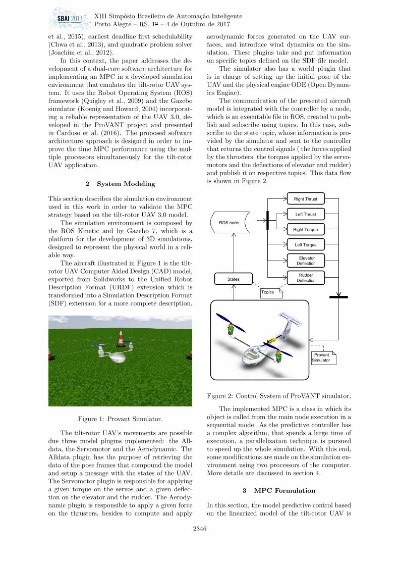
The aircraft illustrated in Figure 1 is the tilt-rotor UAV Computer Aided Design (CAD) model,exported from Solidworks to the Unified RobotDescription Format (URDF) extension which istransformed into a Simulation Description Format(SDF) extension for a more complete description.
Figure 1: Provant Simulator.
The tilt-rotor UAV’s movements are possibledue three model plugins implemented: the All-data, the Servomotor and the Aerodynamic. TheAlldata plugin has the purpose of retrieving thedata of the pose frames that compound the modeland setup a message with the states of the UAV.The Servomotor plugin is responsible for applyinga given torque on the servos and a given deflec-tion on the elevator and the rudder. The Aerody-namic plugin is responsible to apply a given forceon the thrusters, besides to compute and apply
aerodynamic forces generated on the UAV sur-faces, and introduce wind dynamics on the sim-ulation. These plugins take and put informationon specific topics defined on the SDF file model.
The simulator also has a world plugin thatis in charge of setting up the initial pose of theUAV and the physical engine ODE (Open Dynam-ics Engine).
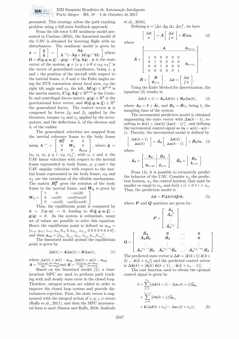
The communication of the presented aircraftmodel is integrated with the controller by a node,which is an executable file in ROS, created to pub-lish and subscribe using topics. In this case, sub-scribe to the state topic, whose information is pro-vided by the simulator and sent to the controllerthat returns the control signals ( the forces appliedby the thrusters, the torques applied by the servo-motors and the deflections of elevator and rudder)and publish it on respective topics. This data flowis shown in Figure 2.
Figure 2: Control System of ProVANT simulator.
The implemented MPC is a class in which itsobject is called from the main node execution in asequential mode. As the predictive controller hasa complex algorithm, that spends a large time ofexecution, a parallelization technique is pursuedto speed up the whole simulation. With this end,some modifications are made on the simulation en-vironment using two processors of the computer.More details are discussed in section 4.
3 MPC Formulation
In this section, the model predictive control basedon the linearized model of the tilt-rotor UAV is
XIII Simposio Brasileiro de Automacao Inteligente
Porto Alegre – RS, 1o – 4 de Outubro de 2017
2346
presented. This strategy solves the path trackingproblem using a full-state feedback approach.
From the tilt-rotor UAV nonlinear model pre-sented in Cardoso (2016), the linearized model ofthe UAV is obtained for hovering flight with nodisturbances. The nonlinear model is given by
x =
[q˙q
]=
[Λq
Λ−1(−Λq +M(q)−1Ω)
],where
Ω = ϑ(q, q,u, ξ) − g(q) −C(q,Λq) , x is the statevector of the system, q = [x y z φ θ ψ αR αL]′ isthe vector of generalized coordinates, being x, yand z the position of the aircraft with respect tothe inertial frame, φ, θ and ψ the Euler angles us-ing the ZYX convention about local axes, αR theright tilt angle and αL the left, M(q) ∈ R8×8 isthe inertia matrix, C(q,Λq) ∈ R8×8 is the Corio-lis and centrifugal forces matrix, g(q) ∈ R8 is thegravitational force vector, and ϑ(q, q,u, ξ) ∈ R8
the generalized forces. The control vector u iscomposed by forces fR and fL applied by thethrusters, torques τR and τL applied by the servo-motors, and the deflections δe of the elevator andδr of the rudder.
The generalized velocities are mapped fromthe inertial reference frame to the body frame
using Λ−1 =
RBI 0 00 Wη 00 0 I2×2
, where q =
[ub vb wb p q r αR αL]′, with u, v and w theUAV linear velocities with respect to the inertialframe represented in body frame, p, q and r theUAV angular velocities with respect to the iner-tial frame represented in the body frame, αR andαL are the variations of the tiltable mechanisms.The matrix RBI gives the rotation of the bodyframe to the inertial frame, and Wη is given by
Wη =
1 0 −sin(θ)0 cos(θ) cos(θ)sin(θ0 −sin(θ) cos(θ)cos(θ)
.Thus, the equilibrium point is computed by
x = f(x,u) = 0, leading to ϑ(q, q,u, ξ) −g(q) = 0. As the system is redundant, manyset of values are possible to solve this equation.Hence the equilibrium point is defined as xeq =
[xref yref zref φeq θeq 0 αReq αLeq 0 0 0 0 0 0 0 0]′,and then ueq = [fReq fLeq τReq τLeq δeeqδreq ]′.
The linearized model around the equilibriumpoint is given by
∆x(t) = A∆x(t) +B∆u(t), (1)
where ∆x(t) = x(t)− xeq, ∆u(t) = u(t)− ueq,
A = ∂f(x,u)∂x
|u=ueqx=xeq and B = ∂f(x,u)
∂u|u=ueqx=xeq .
Based on the linearized model (1), a time-invariant MPC are used to perform path track-ing with null steady state error in the closed loop.Therefore, integral actions are added in order toimprove the closed loop system and provide dis-turbances rejection. First, the state vector is aug-mented with the integral action of x, y, z, ψ errors(Raffo et al., 2011), and then the MPC incremen-tal form is used (Santos and Raffo, 2016; Andrade
et al., 2016).Defining e = [∆x ∆y ∆z ∆ψ]′, we have[
∆xe
]= A
[∆x∫e
]+ B∆u, (2)
where
A =
A 016×4
1 0 0 0 0 00 1 0 0 0 00 0 1 0 0 00 0 0 0 0 1
04×14
,
B =
[B
04×6
], ∆x =
[∆x∫e
].
Using the Euler Method for discretization, theequation (2) results in
∆x(k + 1) = Ad∆x(k) +Bd∆u(k), (3)
where Ad = I + Ats and Bd = Bts, being ts thesampling time of the system.
The incremental predictive model is obtainedaugmenting the state vector with ∆u(k − 1), re-sulting in x(k) = [∆x(k)′∆u(k− 1)′]′, and definingthe incremental control signal as δu = u(k)−u(k−1). Thereby, the incremental model is defined by[
∆x(k + 1)∆u(k)
]= Ad
[∆x(k)
∆u(k − 1)
]+ Bdδu, (4)
where
Ad =
Ad Bd
06×20 I6×6
, Bd =
[BdI6×6
].
From (4), it is possible to recursively predictthe behavior of the UAV. Consider ny the predic-tion horizon, nu the control horizon, that must besmaller or equal to ny, and δu(k+ i) = 0 ∀ i > nu.Thus, the prediction model is
∆x = P∆x(k)Qδu, (5)
where P and Q matrices are given by:
P =
AdAd
2
...Ad
ny
,
Q =
Bd 0 . . . 0AdBd Bd . . . 0
......
. . ....
Adny−1
Bd Adny−2
Bd . . . Adny−nuBd
.The predicted state vector is ∆x = [x(k+1) x(k+2) ... x(k + ny)] and the predicted control vectoris ∆u(k) = [u(k) u(k + 1) ... u(k + nu − 1)].
The cost function used to obtain the optimalcontrol signal is given by
J =
ny∑i=1
‖∆x(k + i)−∆xr(k + i)‖2Wx
+
nu−1∑j=0
‖δu(k + j)‖2Wu
+L(∆x(k + ny)−∆xr(k + ny)), (6)
XIII Simposio Brasileiro de Automacao Inteligente
Porto Alegre – RS, 1o – 4 de Outubro de 2017
2347
where ∆xr(k + i) = xr(k + i) − xr(k) is the fu-ture reference variation, Wx is the diagonal stateweighting matrix, Wu the diagonal control inputweighting matrix, and L is the terminal cost. Theterminal cost is computed by a Lyapunov matrix,which is a solution of the algebraic Riccati equa-tion. In addition, it ensures the closed loop sta-bility of the system (Raffo, 2011).
Aiming to use the qpOASES library, which isan open-source c++ implementation of the onlineactive set strategy (Ferreau et al., 2007–2017), theequation (6) is rewritten in a quadratic program-ming problem as follows:
J =1
2δu′Hδu+ δu′g + f0, (7)
subject to: lbAr ≤ Arδu ≤ ubAr, where
H = 2(Q′WxQ+Wu),
g = 2(P∆x−∆xr)′WxQ,
f0 = (P∆x−∆xr)′Wx(P∆x−∆xr)
+L(∆x(k + ny)−∆xr(k + ny)).
The input constraints used in the MPC arethe physical bounds of the tilt-rotor UAV actua-tors, which are represented by
umin ≤ u(k) ≤ umax. (8)
Besides, the states are limited to improve the per-formance by
xmin ≤ x(k) ≤ xmax. (9)
Since the MPC strategy is based on the modelof the error, the constraints are mapped to incre-mental ones considering also the prediction andcontrol horizons as follows[
∆umin −∆u(k − 1)∆xmin − P∆x(k)
]≤[ImQ
]δu
≤[
∆umax −∆u(k − 1)∆xmax − P∆x(k)
],
(10)
where Im is a lower triangular matrix of identitymatrices.
4 A Multi-Core Software Approach
The simulation time of an application can be im-proved by using a multithreaded code in two pro-cessors instead of using a sequential code. Withthis goal, the software architecture of the MPC forthe tilt-rotor UAV application is proposed assum-ing a dual-core device.
The choices made are based on the rou-tine profile where CommRosManager(), MpcCon-troller() and PredictionModel() methods have thehigher computational costs. The CommRosMan-ager() method is responsible for manager theavailable data from the topics and call the con-troller, the MpcController() computes time vari-ant structures and solve the optimization problem,and the PredictionModel() computes the time in-variant structures.
Therefore, the sequential code is divided ina communication and controller thread aiming toavoid wasting time on independent tasks.
The first thread is in charge of publishing thecontrol inputs on its respective topic and receivingthe states by subscribing to the states topic, asshown in Figure 3.
Figure 3: Flowchart of the communication thread.
The behavior of this thread starts with de-manded initializations, link the node to the inter-ested topics, and then wait the data to be pub-lished on the state topic by the simulator. Thereceived data are the current states of the UAV,which are updated on the shared memory thatis the fastest interprocess communication mecha-nism (Boost, 2017). The operating system mapsa memory segment in the address space of sev-eral processes, so that the other process can readand write in that memory segment without callingoperating system functions. After that, the con-trol signal is read from the memory. If this valuepresents some problem, the previous signal is sentthrough the port.
The second thread is responsible for comput-ing the control signal. Its behavior is presentedin the Flowchart of Figure 4. It starts by ini-tializing the control variables and then taking thestates values from the shared memory. With thisnew value a control signal is calculated, then theshared control vector is updated and the threadwaits until receive new states.
Each of these threads run simultaneously
XIII Simposio Brasileiro de Automacao Inteligente
Porto Alegre – RS, 1o – 4 de Outubro de 2017
2348

Figure 4: Flowchart of the control thread.
in a different core to increase the processingspeed time, and additionally, a parallelizationis proposed on the control thread. This pro-cess counts with the help of the OpenMP (OpenMulti-Processing) (Barbara Chapman, GabrieleJost, 2008), an application programming interfacethat supports multi-platform shared memory mul-tiprocessing programming. It consists of a set ofcompiler directives, library routines, and environ-ment variables that influence run-time behavior.
When we create a parallel region usingOpenMP, the master thread divides itself in otherthreads. At the end of the parallel region, atthe barrier, the threads wait and terminate at thesame time.
Thereby, we start the controller formulationby adding the openMP pragma to compute P andQ matrices (equation 5) like show the Algorithm1.
Algorithm 1 Calculation of P and Q matrices
1: #pragma omp parallel2: id = get the thread number3: if id = 0 then4: Compute Q5: else6: Compute P7: end if
Subsequently, we compute the vectors of con-strains, the weight matrices and some auxiliariesmatrices using the pragmas as follow:
Algorithm 2 Calculation of matrices to predic-tion
1: #pragma omp for firstprivate2: Compute states weight matrix3: #pragma omp for firstprivate4: Compute control weight matrix5: #pragma omp for collapse(2)6: auxiliaries matrices7: Finish the parallel region
To compute the H matrix, we use theOpenMP to activate the internal parallelizationof Eigen library.
Then, we compute the future reference vectorwith the pragma show in the Algorithm 3, andfinish the calculus of the control signal using theinternal Eigen parallelization.
Algorithm 3 Calculation of future reference vec-tor
1: #pragma omp parallel for private2: Compute the reference vector
5 Simulation Results
The UAV physical parameters used in the sim-ulator and to generate the linearized modelare: the mass of the i-th body given inKg by m1 = 1.5538, m2 = 0.0844, m3 =0.0844; the distances between the i-th frames
given in meters by dBC1=
[0 0 0
]′, dBCaux
2=[
0.000678 −0.270482 0.065905]′
, dBCaux3
=[0.000595 0.270515 0.0659005
]′, d
Caux2
C2=[
0 0 0.054]′
, dCaux
3
C3=
[0 0 0.054
]′; the
propellers’ tilt angle β = 4; the thruster’scoefficient Kτ = 1.7 × 10⁻⁷; the BH’s densityof the air ρ = 1.21Kg/m3, b = 9.5 × 10⁻⁶;the i-th aerodynamic surface area in m2
given by sf = 0.20723585,sh = 0.0528758,sv = 0.026482; the gravitational accelerationg = 9.80665m/s2; the distance between theaerodynamic center di and the frame B in meters
given by dBf =[−0.0050 0 0.0326
]′,
dBh =[−0.3858 0 0.1194
]′, dBv =[
−0.3277 0 0.0288]′
, the inertia moment ofthe i-th body
IC1=
4788.34 −1.54722 −363.249∗ 2275.21 0.822828∗ ∗ 6062.31
× 10−5Kg.m2,
IC2=
4.04442 −0.00767 −0.0101488∗ 3.83961 0.119379∗ ∗ 1.58774
×10−5Kg.m2,
IC3=
4.04347 −0.008146 −0.0101554∗ 3.83961 −0.139683∗ ∗ 1.58679
×10−5Kg.m2;
and the aerodynamic coefficients cdfxz(αf ) =
0.4566α2f − 0.0403αf + 0.0601, clfxz
(αf ) =
0.5405αf − 0.0353, cdfxy(βf ) = 0.3513β2
f + 0.0604,
clfxy(βf ) = 0.3821βf − 0.0003, cdvxy
(βv) =
2.2019β2v + 0.0149, clvxy
(βv) = −45.392β3v +
0.0011β2v + 6.1126βv, cr(δr) = 2.1873375δr,
cdhxz(αh) = 1.9382α2
h + 0.0088, clhxz(αf ) =
−35.216α3h + 6.5306αh, ce(δe) = 2.1873375δe.
The equilibrium point of the tilt-rotor UAV isgiven by φ = 3.6864 × 10⁻⁶, θ = 0.0113, αR =αL = −0.0113 in radians, FR = 8.4674, FL =8.4665 in Newton, τR = −1.84335 × 10⁻⁶, τL =−3.1111×10⁻⁶ in N.m and δe = δr = 0 in radians.
To obtain the discrete linear model it was useda sampling time of 12 ms, a prediction horizon of40 and a control horizon of 5.
The simulation time is measured using theoriginal architecture and the proposed one formultiple processors. The performed path by theUAV is presented in Figure 5. These results wereexecuted 37% faster in the parallel structure. It
XIII Simposio Brasileiro de Automacao Inteligente
Porto Alegre – RS, 1o – 4 de Outubro de 2017
2349
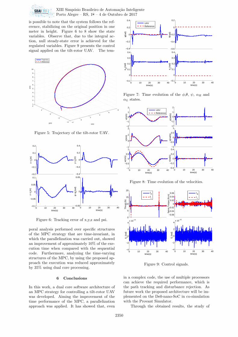
is possible to note that the system follows the ref-erence, stabilizing on the original position in onemeter in height. Figure 6 to 8 show the statevariables. Observe that, due to the integral ac-tion, null steady-state error is achieved for theregulated variables. Figure 9 presents the controlsignal applied on the tilt-rotor UAV. The tem-
−2
0
2
4
6
8
−4
−2
0
2
41
2
3
4
5
6
7
8
9
10
x(m)y(m)
z(m
)
TrajectoryReference
Figure 5: Trajectory of the tilt-rotor UAV.
−0.2
−0.1
0
0.1
0.2
x−x r(m
)
−0.4
−0.2
0
0.2
0.4
y−y r(m
)
0 10 20 30 40−0.1
−0.05
0
0.05
0.1
z−z r(m
)
time(s)0 10 20 30 40
−0.05
0
0.05
ψ−
ψr(r
ad)
time(s)
Figure 6: Tracking error of x,y,z and psi.
poral analysis performed over specific structuresof the MPC strategy that are time-invariant, inwhich the parallelization was carried out, showedan improvement of approximately 10% of the exe-cution time when compared with the sequentialcode. Furthermore, analyzing the time-varyingstructures of the MPC, by using the proposed ap-proach the execution was reduced approximatelyby 35% using dual core processing.
6 Conclusions
In this work, a dual core software architecture ofan MPC strategy for controlling a tilt-rotor UAVwas developed. Aiming the improvement of thetime performance of the MPC, a parallelizationapproach was applied. It has showed that, even
−0.4
−0.2
0
0.2
0.4
φ(ra
d)
−0.6
−0.4
−0.2
0
0.2
θ(ra
d)
0 10 20 30 40−0.1
0
0.1
0.2
0.3
0.4
α R(r
ad)
time(s)0 10 20 30 40
−0.1
0
0.1
0.2
0.3
0.4
α L(rad
)
time(s)
UAVReference
Figure 7: Time evolution of the φ,θ, ψ, αR andαL states.
−2
−1
0
1
2
u(m
/s)
UAVReference
−1
0
1
2v(
m/s
)
0 10 20 30 40−1
−0.5
0
0.5
1
time(s)
w(m
/s)
−2
−1
0
1
2
p(ra
d/s)
−1
−0.5
0
0.5
1
q(ra
d/s)
0 10 20 30 40−0.4
−0.2
0
0.2
0.4
time(s)r(
rad/
s)
Figure 8: Time evolution of the velocities.
0
5
10
15
20
Thr
ust (
N)
fR
fL
−0.06
−0.04
−0.02
0
0.02
0.04
0.06
Ser
vo T
orqu
e (N
.m)
τR
τL
0 10 20 30 40−4
−2
0
2
4x 10
−15
δ e [rad
]
time(s)0 10 20 30 40
−4
−2
0
2
4x 10
−15
δ r [rad
]
time(s)
Figure 9: Control signals.
in a complex code, the use of multiple processorscan achieve the required performance, which isthe path tracking and disturbance rejection. Asfuture work the proposed architecture will be im-plemented on the De0-nano-SoC in co-simulationwith the Provant Simulator.
Through the obtained results, the study of
XIII Simposio Brasileiro de Automacao Inteligente
Porto Alegre – RS, 1o – 4 de Outubro de 2017
2350

time-varying MPC strategies was encouraged,leading to be possible implementing it in a futurework. Another interesting work would be the im-plementation of a parallelized quadratic problemsolver, which spends the longest execution time.
Acknowledgement
This work has been supported by the Brazilianagencies CAPES, CNPq and FAPEMIG.
References
Andrade, R., Raffo, G. V. and Normey-Rico, J. E.(2016). Model Predictive Control of a Tilt-RotorUAV for Load Transportation, European ControlConference (ECC), pp. 2165–2170.
Araar, O. and Aouf, N. (2014). Visual servoing ofa Quadrotor UAV for autonomous power linesinspection, 2014 22nd Mediterranean Confer-ence on Control and Automation, MED 2014pp. 1418–1424.
Barbara Chapman, Gabriele Jost, R. v. d. P. (2008).Using OpenMP: Portable shared memory ParallelProgramming.
Belbachir, A., Escareno, J., Rubio, E. and Sossa, H.(2016). Preliminary results on UAV-based forestfire localization based on decisional navigation,2015 Workshop on Research, Education and De-velopment of Unmanned Aerial Systems, RED-UAS 2015 pp. 377–382.
Boost (2017). Boost C++ Libraries. Last accessed2017-04-20.
Camacho, E. F.; Bordons, C. (2007). Model PredictiveControl, 2 edn.
Cardoso, D. N. (2016). Adaptive Control Strategiesfor Improved Forward Flight of a Tilt-rotor UAVwith Aerodynamic Tail Surfaces, Master’s thesis,Federal University of Minas Gerais.
Cardoso, D. N., Raffo, G. V. and Esteban, S. (2016).A Robust Adaptive Mixing Control for Im-proved Forward Flight of a Tilt-rotor UAV, 2016IEEE 19th International Conference on Intel-ligent Transportation Systems (ITSC) WindsorOceanico Hotel, Rio de Janeiro, Brazil, pp. 1432–1437.
Chwa, H. S., Lee, J., Phan, K. M., Easwaran, A. andShin, I. (2013). Global EDF schedulability anal-ysis for synchronous parallel tasks on multicoreplatforms, Proceedings - Euromicro Conferenceon Real-Time Systems pp. 25–34.
Dhaliwal, S. S. and Ramirez-Serrano, A. (2009). Con-trol of an unconventional VTOL UAV for searchand rescue operations within confined spacesbased on the MARC control architecture, 2009IEEE International Workshop on Safety, Secu-rity and Rescue Robotics, SSRR 2009 .
Ferreau, H., Potschka, A. and Kirches,C. (2007–2017). qpOASES webpage,http://www.qpOASES.org/.
Ge, L., Li, X. and Ng, A. H.-M. (2016). UAV formining applications: A case study at an opencut mine and a longwall mine in new south wales,2016 IEEE International Geoscience and RemoteSensing Symposium (1): 5422–5425.
Joachim, H., Kozma, F. A. and Diehl, M. (2012).A parallel active-set strategy to solve sparseparametric quadratic programs arising in MPC,Vol. 4, IFAC.
Koenig, N. and Howard, A. (2004). Design anduse paradigms for gazebo, an open-source multi-robot simulator, Intelligent Robots and Systems,2004.(IROS 2004). Proceedings. 2004 IEEE/RSJInternational Conference on, Vol. 3, IEEE,pp. 2149–2154.
Lu, H., Halappanavar, M., Chavarria-Miranda, D.,Gebremedhin, A. and Kalyanaraman, A. (2015).Balanced Coloring for Parallel Computing Appli-cations, Proceedings - 2015 IEEE 29th Interna-tional Parallel and Distributed Processing Sym-posium, IPDPS 2015 pp. 7–16.
Quigley, M., Conley, K., Gerkey, B., Faust, J., Foote,T., Leibs, J., Wheeler, R. and Ng, A. Y. (2009).Ros: an open-source robot operating system,ICRA workshop on open source software, Vol. 3,Kobe, Japan, p. 5.
Raffo, G. (2011). Robust Control Strategies for aQuadRotor Helicopter: an Underactuated Me-chanical System, PhD thesis, Universidad deSevilla Escuela.
Raffo, G. V., Ortega, M. G. and Rubio, F. R. (2011).Nonlinear H∞ controller for the quad-rotor he-licopter with input coupling, IFAC Proceed-ings Volumes (IFAC-PapersOnline) 4(1): 13834–13839.
Rego, B. S. and Raffo, G. V. (2016). Suspendedload path tracking control based on zonotopicstate estimation using a tilt-rotor UAV, 2016IEEE 19th International Conference on Intel-ligent Transportation Systems (ITSC) WindsorOceanico Hote, Rio de Janeiro, Brazil, pp. 1445–1451.
Santos, M. A. and Raffo, G. V. (2016). Path Track-ing Model Predictive Control of a Tilt-rotor UAVCarrying a Suspended Load, 2016 IEEE 19th In-ternational Conference on Intelligent Transporta-tion Systems (ITSC) Windsor Oceanico Hotel,Rio de Janeiro, Brazil, pp. 1458–1463.
Tariq, A., Osama, S. and Gillani, A. (2016). Develop-ment of a Low Cost and Light Weight UAV forPhotogrammetry and Precision Land MappingUsing Aerial Imagery, 2016 International Con-ference on Frontiers of Information Technology(FIT) pp. 360–364.
Vega, A., Lin, C.-c. and Swaminathan, K. (2015).Resilient , UAV-Embedded Real-Time Comput-ing, 2015 33rd IEEE International Conference onComputer Design (ICCD), pp. 736–739.
XIII Simposio Brasileiro de Automacao Inteligente
Porto Alegre – RS, 1o – 4 de Outubro de 2017
2351


![PREFEITURA MUNICIPAL DE ITABUNA · E&L Contabilidade Pública Eletrônica [S] Page 1 of 1 E&L Produções de Software LTDA ... Page 1 of 2 E&L Produções de Software LTDA. Receita](https://static.fdocumentos.com/doc/165x107/5e33b559cff9a23c05664c5c/prefeitura-municipal-de-itabuna-el-contabilidade-pblica-eletrnica-s-page.jpg)
