
Aula%15%(%Estudode Torçãoe Ângulode Torção. · 2014-02-17 · 1)As...
19
Prof. Wanderson S. Paris [email protected] MECÂNICA DOS SÓLIDOS Aula 15 Estudo de Torção e Ângulo de Torção. Prof. Wanderson S. Paris, M.Eng. [email protected]
Transcript of Aula%15%(%Estudode Torçãoe Ângulode Torção. · 2014-02-17 · 1)As...
Prof. Wanderson S. Paris -‐ [email protected] MECÂNICA DOS SÓLIDOS
Aula 15 -‐ Estudo de Torção e Ângulo de Torção. Prof. Wanderson S. Paris, M.Eng.
Prof. Wanderson S. Paris -‐ [email protected] MECÂNICA DOS SÓLIDOS
Ângulo de Torção
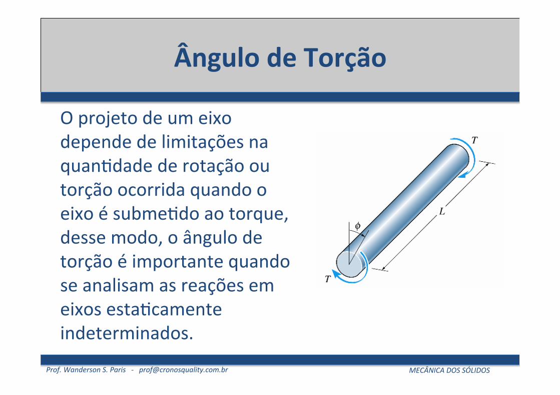
O projeto de um eixo depende de limitações na quan5dade de rotação ou torção ocorrida quando o eixo é subme5do ao torque, desse modo, o ângulo de torção é importante quando se analisam as reações em eixos esta5camente indeterminados.
Prof. Wanderson S. Paris -‐ [email protected] MECÂNICA DOS SÓLIDOS
Ângulo de Torção
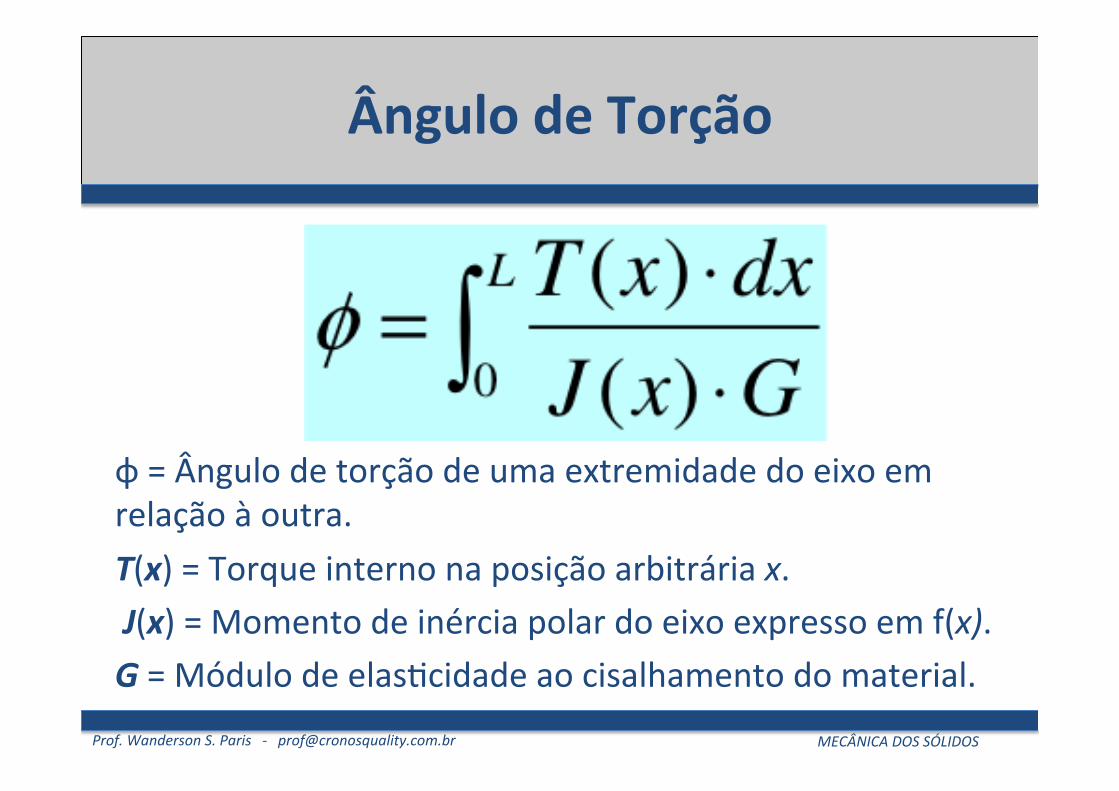
φ = Ângulo de torção de uma extremidade do eixo em relação à outra. T(x) = Torque interno na posição arbitrária x. J(x) = Momento de inércia polar do eixo expresso em f(x). G = Módulo de elas5cidade ao cisalhamento do material.
Prof. Wanderson S. Paris -‐ [email protected] MECÂNICA DOS SÓLIDOS
Cálculo para Área e Torque Constantes
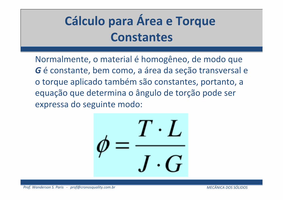
Normalmente, o material é homogêneo, de modo que G é constante, bem como, a área da seção transversal e o torque aplicado também são constantes, portanto, a equação que determina o ângulo de torção pode ser expressa do seguinte modo:
Prof. Wanderson S. Paris -‐ [email protected] MECÂNICA DOS SÓLIDOS
Cálculo para Área e Torque Constantes
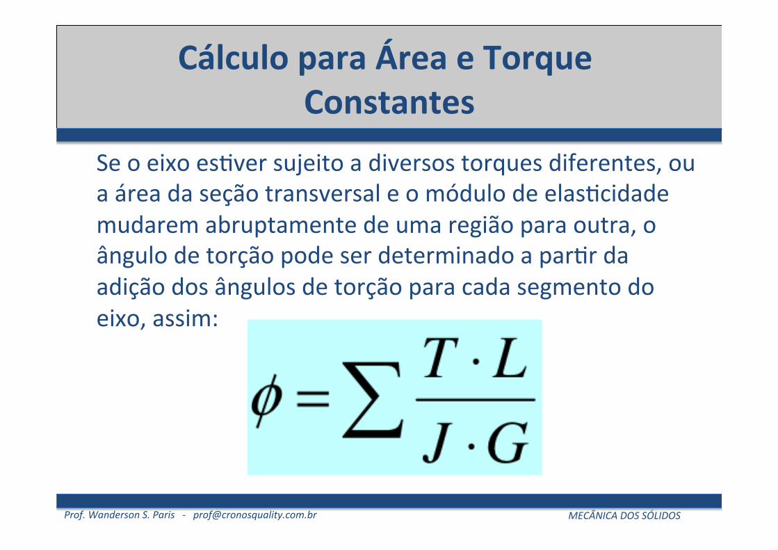
Se o eixo es5ver sujeito a diversos torques diferentes, ou a área da seção transversal e o módulo de elas5cidade mudarem abruptamente de uma região para outra, o ângulo de torção pode ser determinado a par5r da adição dos ângulos de torção para cada segmento do eixo, assim:
Prof. Wanderson S. Paris -‐ [email protected] MECÂNICA DOS SÓLIDOS
Convenção de Sinais
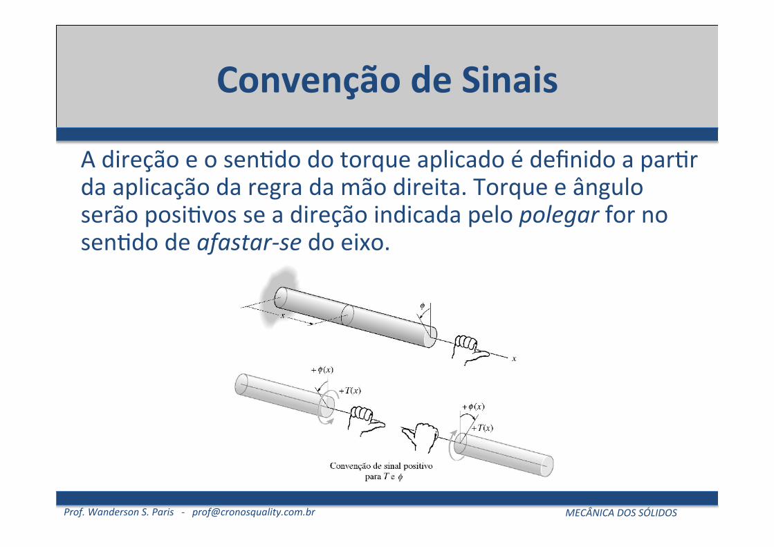
A direção e o sen5do do torque aplicado é definido a par5r da aplicação da regra da mão direita. Torque e ângulo serão posi5vos se a direção indicada pelo polegar for no sen5do de afastar-‐se do eixo.
Prof. Wanderson S. Paris -‐ [email protected] MECÂNICA DOS SÓLIDOS
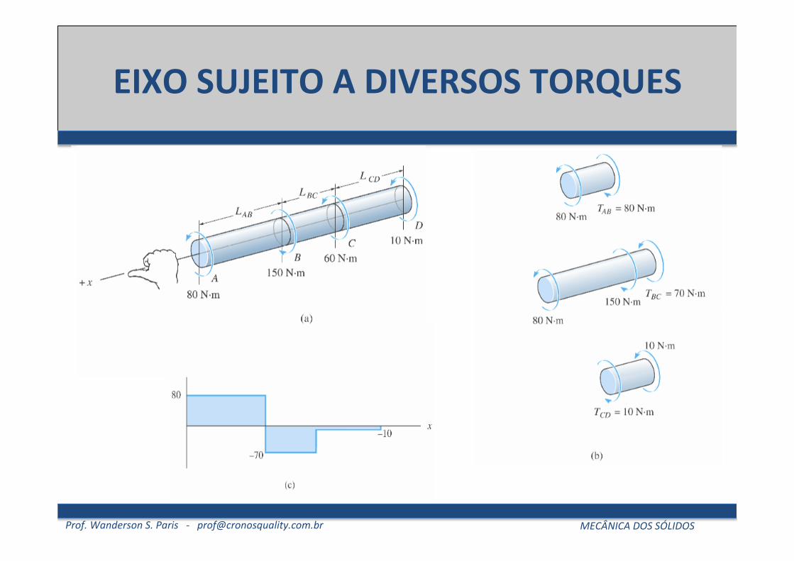
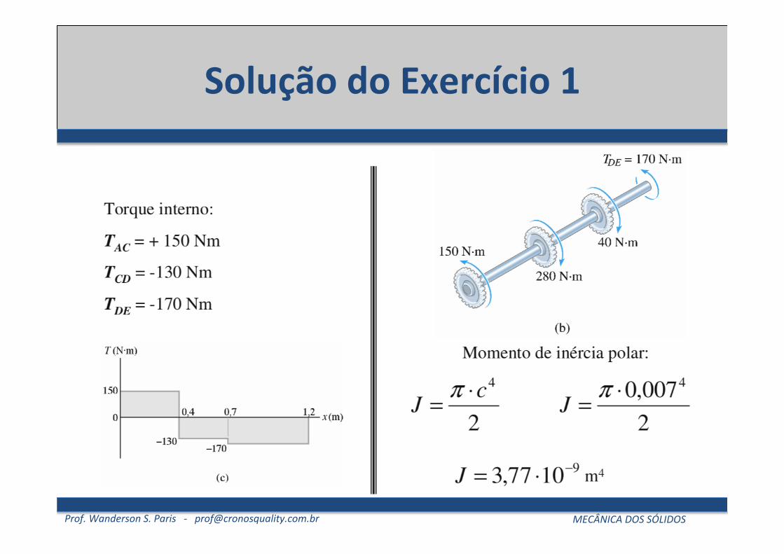
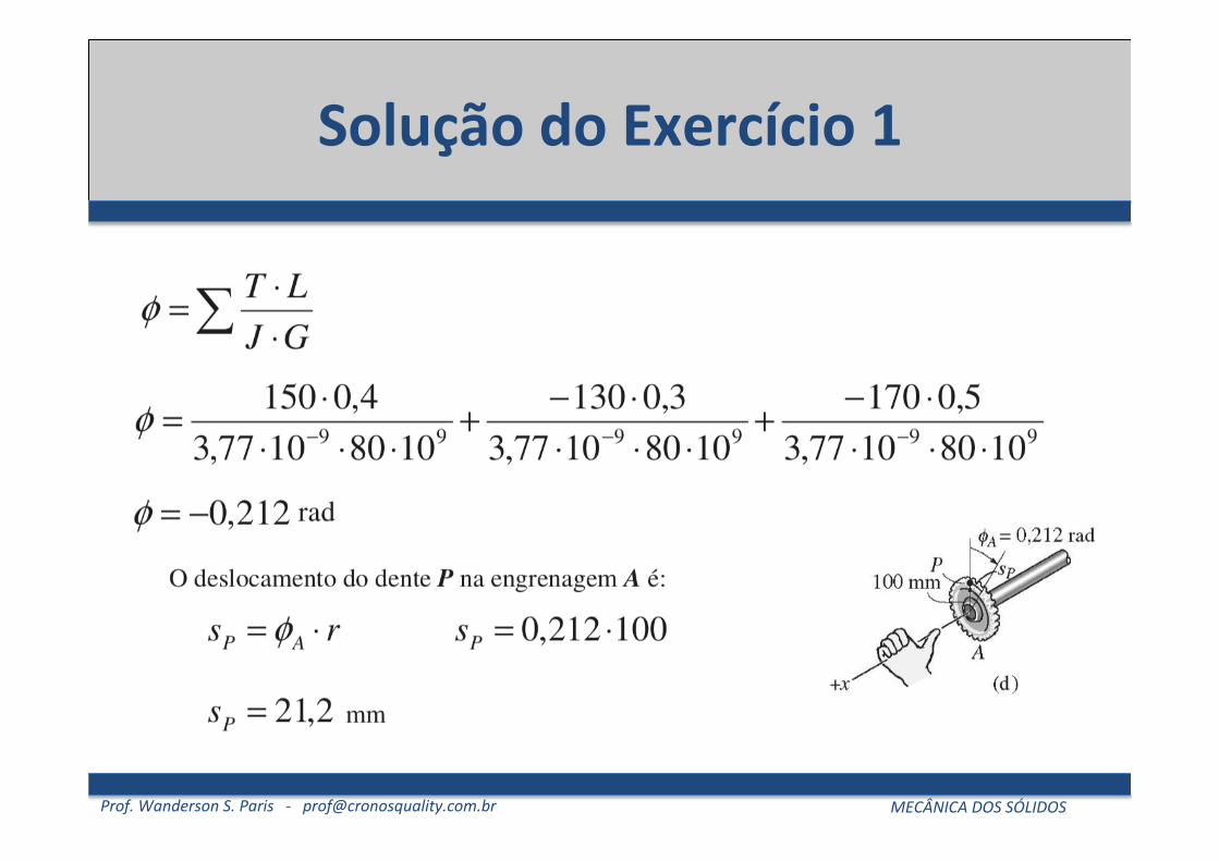
Exercício 1
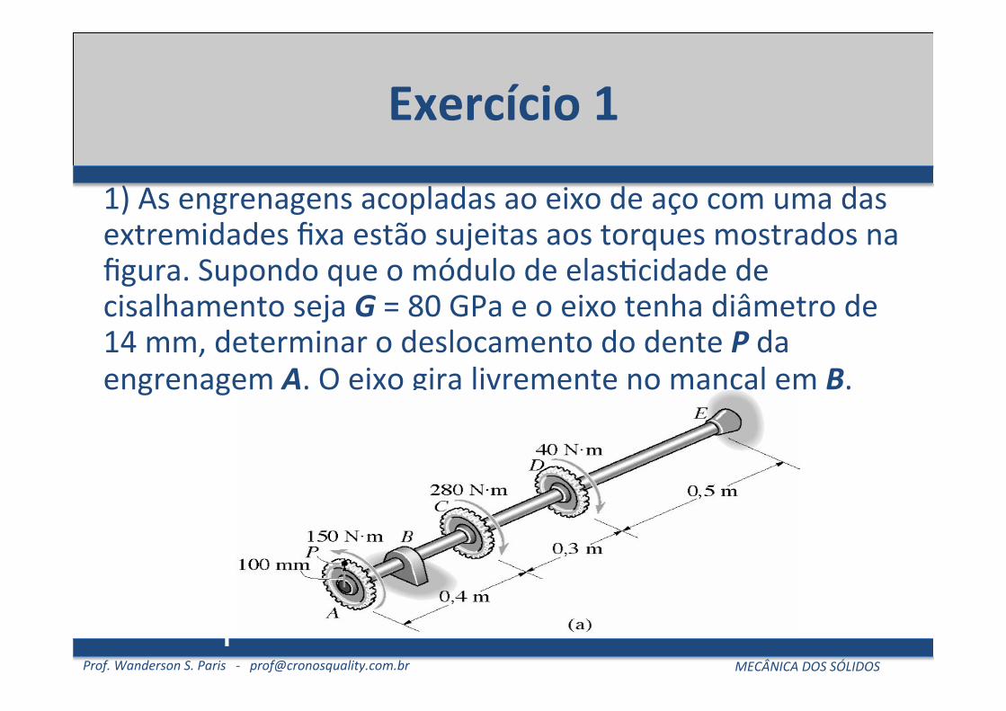
1) As engrenagens acopladas ao eixo de aço com uma das extremidades fixa estão sujeitas aos torques mostrados na figura. Supondo que o módulo de elas5cidade de cisalhamento seja G = 80 GPa e o eixo tenha diâmetro de 14 mm, determinar o deslocamento do dente P da engrenagem A. O eixo gira livremente no mancal em B.
Prof. Wanderson S. Paris -‐ [email protected] MECÂNICA DOS SÓLIDOS
Exercício 2
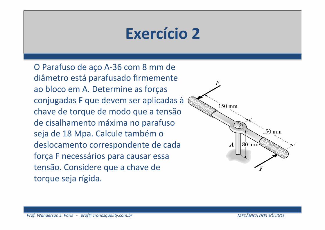
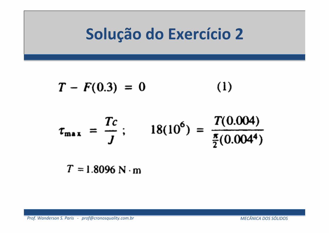
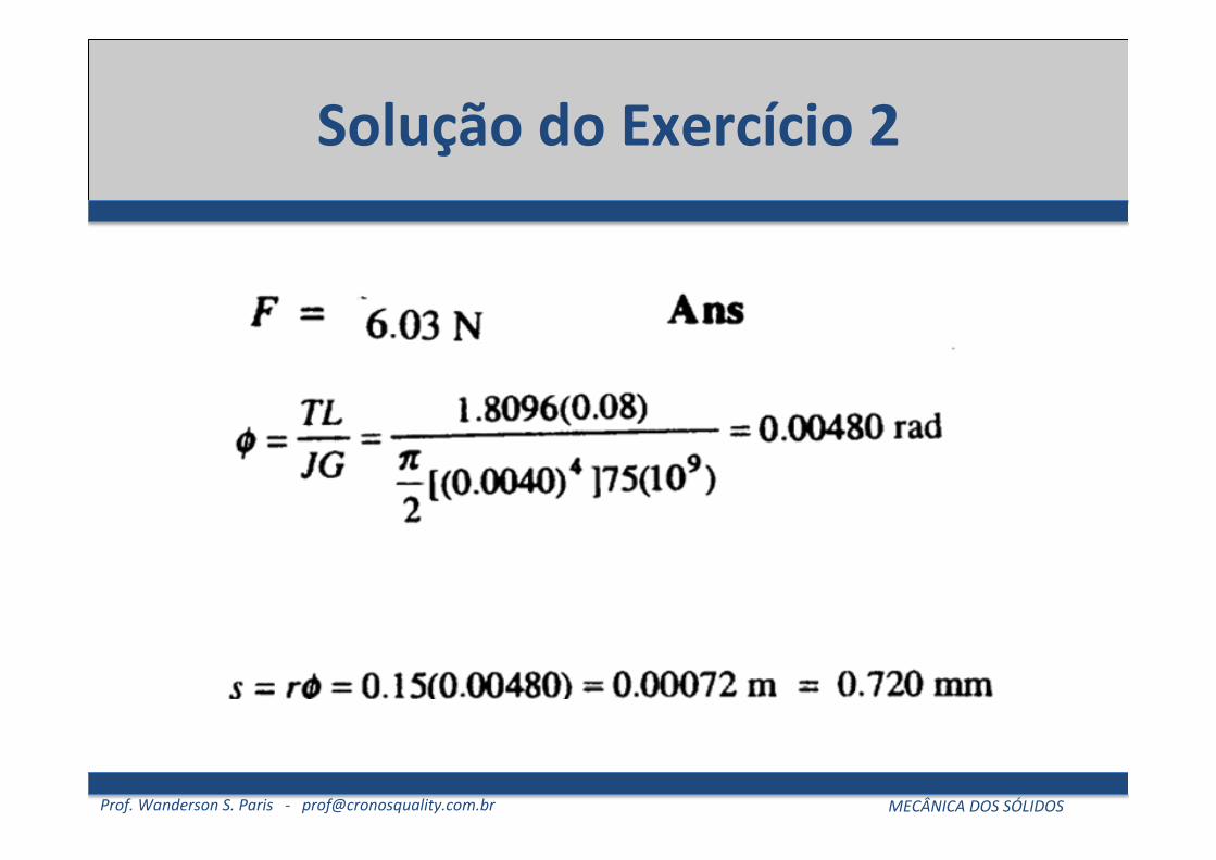
O Parafuso de aço A-‐36 com 8 mm de diâmetro está parafusado firmemente ao bloco em A. Determine as forças conjugadas F que devem ser aplicadas à chave de torque de modo que a tensão de cisalhamento máxima no parafuso seja de 18 Mpa. Calcule também o deslocamento correspondente de cada força F necessários para causar essa tensão. Considere que a chave de torque seja rígida.
© 2008 by R.C. Hibbeler. Published by Pearson Prentice Hall, Pearson Education, Inc., Upper Saddle River, NJ. All rights reserved. This material is protected under allcopyright laws as they currently exist. No portion of this material may be reproduced, in any form or by any means, without permission in writing from the publisher.
186
c05.qxd 9/19/07 8:16 PM Page 186
Prof. Wanderson S. Paris -‐ [email protected] MECÂNICA DOS SÓLIDOS
Solução do Exercício 2
© 2008 by R.C. Hibbeler. Published by Pearson Prentice Hall, Pearson Education, Inc., Upper Saddle River, NJ. All rights reserved. This material is protected under allcopyright laws as they currently exist. No portion of this material may be reproduced, in any form or by any means, without permission in writing from the publisher.
186
c05.qxd 9/19/07 8:16 PM Page 186
Prof. Wanderson S. Paris -‐ [email protected] MECÂNICA DOS SÓLIDOS
Exercícios Propostos
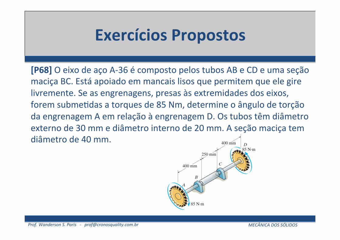
[P68] O eixo de aço A-‐36 é composto pelos tubos AB e CD e uma seção maciça BC. Está apoiado em mancais lisos que permitem que ele gire livremente. Se as engrenagens, presas às extremidades dos eixos, forem subme5das a torques de 85 Nm, determine o ângulo de torção da engrenagem A em relação à engrenagem D. Os tubos têm diâmetro externo de 30 mm e diâmetro interno de 20 mm. A seção maciça tem diâmetro de 40 mm.
5.4 ANGLE OF TWIST 209
5
5–47. The propellers of a ship are connected to a A-36steel shaft that is 60 m long and has an outer diameter of340 mm and inner diameter of 260 mm. If the power output is4.5 MW when the shaft rotates at determine themaximum torsional stress in the shaft and its angle of twist.
*5–48. A shaft is subjected to a torque T. Compare theeffectiveness of using the tube shown in the figure with thatof a solid section of radius c. To do this, compute the percentincrease in torsional stress and angle of twist per unit lengthfor the tube versus the solid section.
20 rad>s,
5–50. The hydrofoil boat has an A-36 steel propellershaft that is 100 ft long. It is connected to an in-line dieselengine that delivers a maximum power of 2500 hp andcauses the shaft to rotate at 1700 rpm. If the outerdiameter of the shaft is 8 in. and the wall thickness is determine the maximum shear stress developed in theshaft. Also, what is the “wind up,” or angle of twist in theshaft at full power?
38 in.,
PROBLEMS
T
T
c
c
c2
Prob. 5–48
400 mm
400 mm
250 mm85 N m!
85 N m!
A
B
C
D
Prob. 5–49
•5–49. The A-36 steel axle is made from tubes AB and CDand a solid section BC. It is supported on smooth bearingsthat allow it to rotate freely. If the gears, fixed to its ends, aresubjected to torques, determine the angle of twistof gear A relative to gear D. The tubes have an outerdiameter of 30 mm and an inner diameter of 20 mm. Thesolid section has a diameter of 40 mm.
85-N # m
100 ft
Prob. 5–50
A
B
Probs. 5–51/52
5–51. The engine of the helicopter is delivering 600 hpto the rotor shaft AB when the blade is rotating at1200 Determine to the nearest the diameterof the shaft AB if the allowable shear stress is and the vibrations limit the angle of twist of the shaft to0.05 rad. The shaft is 2 ft long and made from L2 steel.
*5–52. The engine of the helicopter is delivering 600 hpto the rotor shaft AB when the blade is rotating at1200 Determine to the nearest the diameter ofthe shaft AB if the allowable shear stress is and the vibrations limit the angle of twist of the shaft to0.05 rad. The shaft is 2 ft long and made from L2 steel.
tallow = 10.5 ksi
18 in.rev>min.
tallow = 8 ksi
18 in.rev>min.
Prof. Wanderson S. Paris -‐ [email protected] MECÂNICA DOS SÓLIDOS
Exercícios Propostos
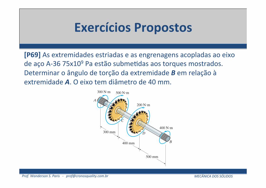
[P69] As extremidades estriadas e as engrenagens acopladas ao eixo de aço A-‐36 75x109 Pa estão subme5das aos torques mostrados. Determinar o ângulo de torção da extremidade B em relação à extremidade A. O eixo tem diâmetro de 40 mm.
210 CHAPTER 5 TORS ION
•5–53. The 20-mm-diameter A-36 steel shaft is subjectedto the torques shown. Determine the angle of twist of theend B.
5
5–54. The assembly is made of A-36 steel and consists of asolid rod 20 mm in diameter fixed to the inside of a tubeusing a rigid disk at B. Determine the angle of twist at D.The tube has an outer diameter of 40 mm and wall thicknessof 5 mm.
5–55. The assembly is made of A-36 steel and consists of asolid rod 20 mm in diameter fixed to the inside of a tubeusing a rigid disk at B. Determine the angle of twist at C.The tube has an outer diameter of 40 mm and wall thicknessof 5 mm.
A
80 N!m
20 N!m
30 N!mB
D
C
800 mm
600 mm200 mm
Prob. 5–53
0.4 mB
D
C
0.3 m
0.1 m
60 N!m
150 N!m
A
Probs. 5–54/55
*5–56. The splined ends and gears attached to the A-36steel shaft are subjected to the torques shown. Determinethe angle of twist of end B with respect to end A. The shafthas a diameter of 40 mm.
300 N!m
A200 N!m
500 N!m
300 mm
400 mm
500 mm
400 N!m
B
D
C
Prob. 5–56
6 in.
8 in.
10 in.
A
B
C
D
Probs. 5–57/58
•5–57. The motor delivers 40 hp to the 304 stainless steelshaft while it rotates at 20 Hz. The shaft is supported onsmooth bearings at A and B, which allow free rotation ofthe shaft.The gears C and D fixed to the shaft remove 25 hpand 15 hp, respectively. Determine the diameter of theshaft to the nearest if the allowable shear stress is
and the allowable angle of twist of C withrespect to D is 0.20 .
5–58. The motor delivers 40 hp to the 304 stainless steelsolid shaft while it rotates at 20 Hz.The shaft has a diameterof 1.5 in. and is supported on smooth bearings at A and B,which allow free rotation of the shaft. The gears C and Dfixed to the shaft remove 25 hp and 15 hp, respectively.Determine the absolute maximum stress in the shaft andthe angle of twist of gear C with respect to gear D.
°tallow = 8 ksi
18 in.
Prof. Wanderson S. Paris -‐ [email protected] MECÂNICA DOS SÓLIDOS
Exercícios Propostos
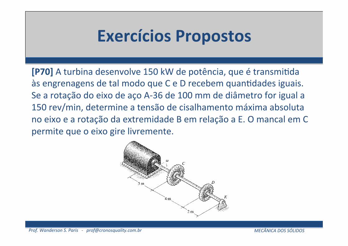
[P70] A turbina desenvolve 150 kW de potência, que é transmi5da às engrenagens de tal modo que C e D recebem quan5dades iguais. Se a rotação do eixo de aço A-‐36 de 100 mm de diâmetro for igual a 150 rev/min, determine a tensão de cisalhamento máxima absoluta no eixo e a rotação da extremidade B em relação a E. O mancal em C permite que o eixo gire livremente.
Prof. Wanderson S. Paris -‐ [email protected] MECÂNICA DOS SÓLIDOS
Exercícios Propostos
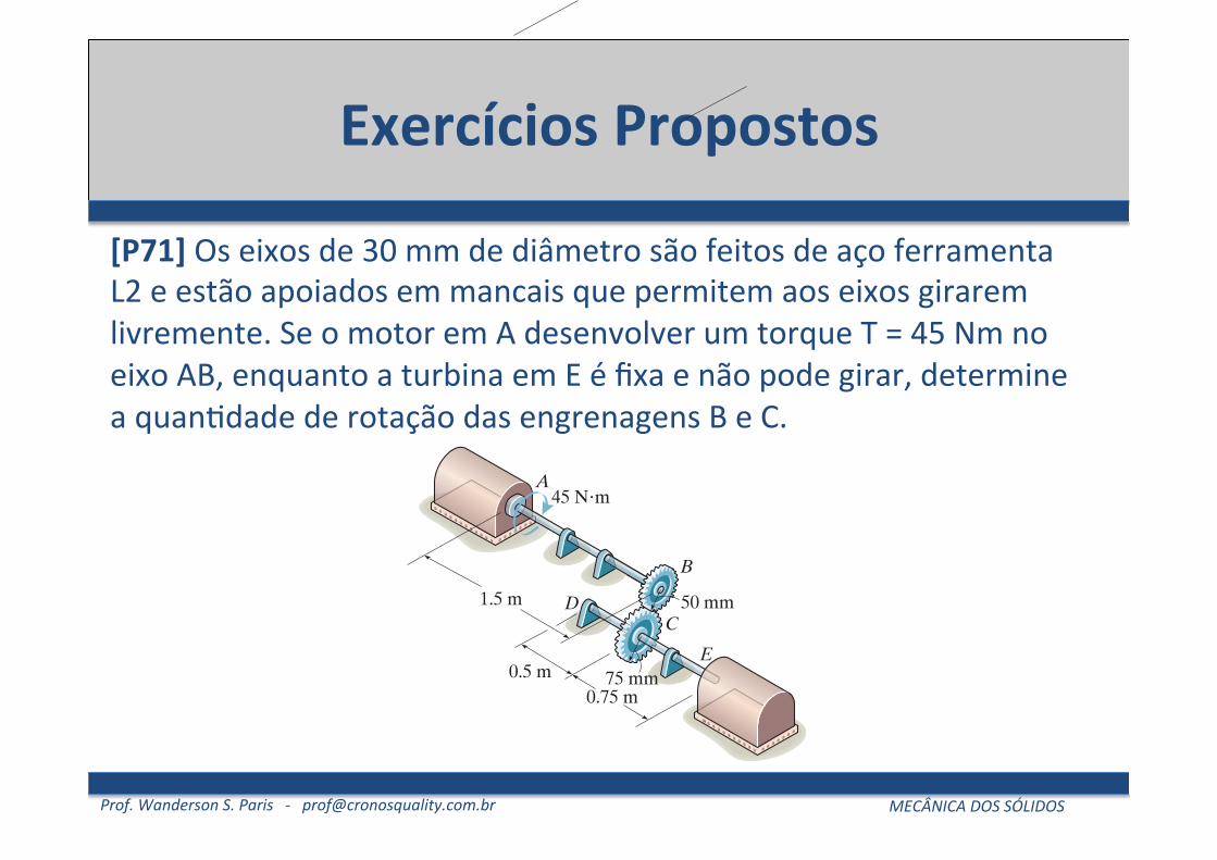
[P71] Os eixos de 30 mm de diâmetro são feitos de aço ferramenta L2 e estão apoiados em mancais que permitem aos eixos girarem livremente. Se o motor em A desenvolver um torque T = 45 Nm no eixo AB, enquanto a turbina em E é fixa e não pode girar, determine a quan5dade de rotação das engrenagens B e C.
212 CHAPTER 5 TORS ION
5–66. The 60-mm diameter shaft ABC is supported by twojournal bearings, while the 80-mm diameter shaft EH isfixed at E and supported by a journal bearing at H. If
and , determine the angle oftwist of gears A and C. The shafts are made of A-36 steel.
5–67. The 60-mm diameter shaft ABC is supported by twojournal bearings, while the 80-mm diameter shaft EH is fixedat E and supported by a journal bearing at H. If the angleof twist at gears A and C is required to be 0.04 rad,determine the magnitudes of the torques T1 and T2. Theshafts are made of A-36 steel.
T2 = 4 kN # mT1 = 2 kN # m
5
*5–68. The 30-mm-diameter shafts are made of L2 toolsteel and are supported on journal bearings that allow theshaft to rotate freely. If the motor at A develops a torque of
on the shaft AB, while the turbine at E is fixedfrom turning, determine the amount of rotation of gears Band C.
T = 45 N # m
600 mm
100 mm
600 mm
900 mm
DAE
H
B
CT1
T2
75 mm
Probs. 5–66/67
45 N!mA
0.75 m
50 mm1.5 m
0.5 m
B
C
E
D
75 mm
Prob. 5–68
•5–69. The shafts are made of A-36 steel and each has adiameter of 80 mm. Determine the angle of twist at end E.
5–70. The shafts are made of A-36 steel and each has adiameter of 80 mm. Determine the angle of twist of gear D.
AB
C
D
E
0.6 m
0.6 m
0.6 m
150 mm
200 mm
150 mm
10 kN!m
2 kN!m
Probs. 5–69/70
A
T1
T2
Tn
d1d2
dn
L1
L2
Lm
Prob. 5–71
5–71. Consider the general problem of a circular shaftmade from m segments, each having a radius of and shearmodulus If there are n torques on the shaft as shown,write a computer program that can be used to determinethe angle of twist of its end A. Show an application of theprogram using the values
d2 = 0.8 m.T2 = 600 N # m,d1 = 0.25 m,T1 = -450 N # m,G2 = 15 GPa,c2 = 0.05 m,L2 = 1.5 m,G1 = 30 GPa,c1 = 0.02 m,L1 = 0.5 m,
Gm .cm
Prof. Wanderson S. Paris -‐ [email protected] MECÂNICA DOS SÓLIDOS
Exercícios Propostos
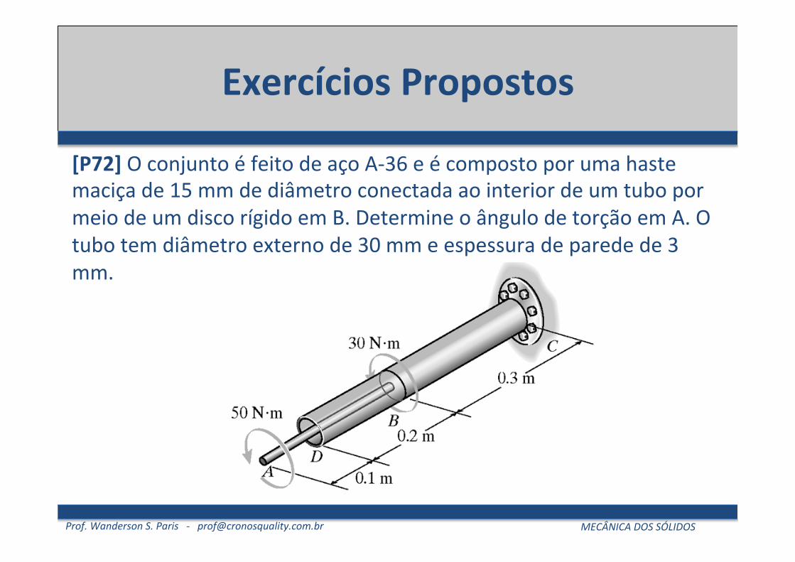
[P72] O conjunto é feito de aço A-‐36 e é composto por uma haste maciça de 15 mm de diâmetro conectada ao interior de um tubo por meio de um disco rígido em B. Determine o ângulo de torção em A. O tubo tem diâmetro externo de 30 mm e espessura de parede de 3 mm.
© 2008 by R.C. Hibbeler. Published by Pearson Prentice Hall, Pearson Education, Inc., Upper Saddle River, NJ. All rights reserved. This material is protected under allcopyright laws as they currently exist. No portion of this material may be reproduced, in any form or by any means, without permission in writing from the publisher.
191
c05.qxd 9/19/07 8:17 PM Page 191

Prof. Wanderson S. Paris -‐ [email protected] MECÂNICA DOS SÓLIDOS
Referências Bibliográficas
• hJp://www.cronosquality.com/aulas/ms/index.html • Hibbeler, R. C. -‐ Resistência dos Materiais, 7.ed. São
Paulo :Pearson Pren5ce Hall, 2010. • BEER, F.P. e JOHNSTON, JR., E.R. Resistência dos Materiais, 3.o
Ed., Makron Books, 1995. • Rodrigues, L. E. M. J. Resistência dos Materiais, Ins5tuto Federal
de Educação, Ciência e Tecnologia – São Paulo: 2009. • BUFFONI, S.S.O. Resistência dos Materiais, Universidade Federal
Fluminense – Rio de Janeiro: 2008.