
CHECKERBOARD-FREE TOPOLOGY OPTIMIZATION USING … · CHECKERBOARD-FREE TOPOLOGY OPTIMIZATION USING...
10
CHECKERBOARD-FREE TOPOLOGY OPTIMIZATION USING POLYGONAL FINITE ELEMENTS Anderson Pereira a , Cameron Talischi b , Ivan F. M. Menezes a and Glaucio H. Paulino b a Tecgraf (Group of Technology in Computer Graphics), Pontifical Catholic University of Rio de Janeiro (PUC–Rio), Rua Marquês de São Vicente, 225, 22453-900, Rio de Janeiro, RJ, Brazil, {anderson,ivan}@tecgraf.puc-rio.br, http://www.tecgraf.puc-rio.br b Department of Civil and Environmental Engineering, University of Illinois at Urbana-Champaign, Newmark Laboratory, 205 North Mathews Avenue, Urbana, IL, 61801, U.S.A. {ktalisch,paulino}@uiuc.edu, http:// cee.illinois.edu Keywords: topology optimization, polygonal elements, Voronoi tessellations Abstract. The checkerboard layout of material distribution is one of a number of serious numerical anomalies encountered in the solution of topology optimization problems. Regularization schemes such as filtering can be used to suppress the numerical instabilities, but these measures often involve heuris- tic parameters that can augment the optimization problem. Polygonal elements can be very useful in this aspect since they naturally exclude checkerboard layouts and provide flexibility in discretizing com- plex domains. Examples considering compliance minimization and compliant mechanism are presented that demonstrate the advantages of the proposed elements in achieving checkerboard-free solutions and avoiding one-node connections from the design optimization process. Potential extensions and impact of this work will also be discussed.
Transcript of CHECKERBOARD-FREE TOPOLOGY OPTIMIZATION USING … · CHECKERBOARD-FREE TOPOLOGY OPTIMIZATION USING...
CHECKERBOARD-FREE TOPOLOGY OPTIMIZATION USINGPOLYGONAL FINITE ELEMENTS
Anderson Pereiraa, Cameron Talischib, Ivan F. M. Menezesa and Glaucio H. Paulinob
aTecgraf (Group of Technology in Computer Graphics), Pontifical Catholic University of Rio de Janeiro(PUC–Rio), Rua Marquês de São Vicente, 225, 22453-900, Rio de Janeiro, RJ, Brazil,
anderson,[email protected], http://www.tecgraf.puc-rio.br
bDepartment of Civil and Environmental Engineering, University of Illinois at Urbana-Champaign,Newmark Laboratory, 205 North Mathews Avenue, Urbana, IL, 61801, U.S.A.
ktalisch,[email protected], http://cee.illinois.edu
Keywords: topology optimization, polygonal elements, Voronoi tessellations
Abstract. The checkerboard layout of material distribution is one of a number of serious numericalanomalies encountered in the solution of topology optimization problems. Regularization schemes suchas filtering can be used to suppress the numerical instabilities, but these measures often involve heuris-tic parameters that can augment the optimization problem. Polygonal elements can be very useful inthis aspect since they naturally exclude checkerboard layouts and provide flexibility in discretizing com-plex domains. Examples considering compliance minimization and compliant mechanism are presentedthat demonstrate the advantages of the proposed elements in achieving checkerboard-free solutions andavoiding one-node connections from the design optimization process. Potential extensions and impact ofthis work will also be discussed.
1 INTRODUCTION
The main focus of this work is the numerical instabilities that plague the finite element so-lutions to the topology optimization problems. The appearance of such spurious solution isattributed to the poor modeling of the response field (displacements in structural optimizationapplications) stemming from an inappropriate choice of finite element discretizations. Theformation of the so-called checkerboard patterns, for example, has been attributed to the ar-tificially high stiffness of lower order quad or triangular elements (Diaz and Sigmund, 1995;Jog and Haber, 1996). The alternating void-solid checkerboard patterns avoid penalizationimposed on the intermediate densities and are therefore favored in compliance minimizationand compliant mechanism problems. It has been previously observed that higher order ele-ments (Sigmund and Petersson, 1998) and non-conforming elements (Jang et al., 2003) are lesssusceptible to the appearance of such solutions.
In Talischi et al. (2009), it was noted that the discretization of the density field also playsa role in the appearance of checkerboard patterns. The exclusion of one-one connections in ahexagonal mesh naturally excludes such designs. In the extension of that work (Talischi et al.,2010), it was shown that general convex polygonal discretizations also enjoy numerical stability.Additionally, they provide more flexibility in mesh generation and impose less constraint in theformation of optimal designs, which as a result are less mesh-dependent.
In the present work, we continue our investigation of the use of polygonal discretizations instructural topology optimization applications. We present benchmark compliance minimizationand compliant mechanism problems and compare the performance of polygonal element tostandard bilinear elements.
2 FORMULATIONS
The discrete form of the problem is mathematically given by:
min J (ρ,u)ρ
s.t.: K(ρ)u = f∫
ΩS
dV ≤ Vs
(1)
Here J (ρ,u) is the cost function that characterizes the performance of each design; f andu are the global force and displacement vectors; K denotes the global stiffness matrix, whichis dependent on the design variable ρ; and Vs is the upper bound on the volume of the designdenoted by ΩS .
The minimum compliance problem is given by:
J (ρ,u) = fTu (2)
while for the compliant mechanism, we have:
J (ρ,u) = lTu (3)
where l is a vector composed of zeros except the degree of the output position which is one.The common choice of design parametrization is to take ρ as the material “density”: by
convention, ρ = 1 at a point signifies a material region while ρ = 0 represents void. The
intermediate values are penalized according to the following scheme:
E(ρ) = ρpE0, p > 1 (4)
Here E(ρ) is the material stiffness of a point with density ρ, while E0 denotes the stiffnessof the solid phase (corresponding to ρ = 1). For values of p greater than 1 (usually we takep ≥ 3), the stiffness of intermediate densities is penalized through the power law relation, sothey are not favored. As a result, the final design consists primarily of solid and void regions.This approach is known as the Solid Isotropic Material with Penalization (SIMP), and readersare referred to Bendsøe (1989); Zhou and Rozvany (1991); Bendsøe and Sigmund (2003) formore information.
We have considered the following discretizations of the density field: (1) Element-based (2)Projection scheme.
2.1 Element-based approach:
In this approach, a constant density value is assigned to each displacement finite element.These element densities ρe are then used as the design variables for the optimization problem(1). It is in this context that the checkerboard appears: the density of adjacent elements alter-nates between zero and one, while the patch of element maintains the connectivity resemblingthat of a checkerboard.
For the present formulation, as mentioned before, convex polygonal elements are used toconstruct the finite element discretization. Therefore, the element-based approach with sucha discretization does not favor spurious checkerboard-like patterns. Furthermore, polygonalmeshes can remove the restrictions on the orientation of the structural members and the finaltopology as arbitrary polygonal elements have less directional bias when compared to quadri-lateral elements. For example, hexagonal element has more lines of symmetry per elementcompared to the triangular and square elements.
The polygonal finite element mesh can be constructed using a Voronoi diagram of the nodesthat cover the design domain.
The interpolation space on the polygonal mesh is constructed using Laplace (natural neigh-bor) shape functions as described in Sukumar and Malsch (2006); Sukumar and Tabarraei (2004).These shape functions yield a conforming finite element, and satisfy the necessary approxima-bility conditions of constant and linear precision, and exhibit desirable properties such as par-tition of unity. Moreover, they provide an isoparametric transformation map that allows thecomputations to be carried out on a parent element. For more details on the implementation ofthese elements, we refer the reader to the references mentioned above.
2.2 Projection scheme:
In this approach (Guest et al., 2004), the density of each element is obtained by a weightedaverage of the values of the design variables in the adjacent elements. In particular, the projec-tion is carried out as:
ρe =
∑i widi∑i wi
(5)
As before, ρe is the element density; di is the design variable associated to element i, and wi are
the weighting functions defined by:
wi = max(
rmin − ri
rmin
, 0
)(6)
Here ri is the distance between the centroid of element i to the centroid of element e, and rmin
is a prescribed radius of projection. We can see that the projection has an embedded physicallength scale rmin that is independent of the mesh size. As such, this scheme addresses the issueof mesh-dependency in topology optimization by limiting the space of admissible solutions tothe design having members larger than a minimum physical size.
3 NUMERICAL RESULTS
In this section, numerical results are presented to confirm the checkerboard-free design byusing polygonal elements. Both compliance minimization and compliant mechanism are con-sidered. The optimization problem is solved using the Optimality Criteria (OC) developedby Bendsøe and Sigmund (2003). Also, to avoid getting trapped at a local minima, a continua-tion method is used on the value of SIMP penalty exponent: p is increased (with increment of0.5) from 1 to 3 after the maximum change in the design variables is less than a given toleranceof 0.01. The maximum number of iterations per value of p used was 100.
3.1 Compliance minimization example
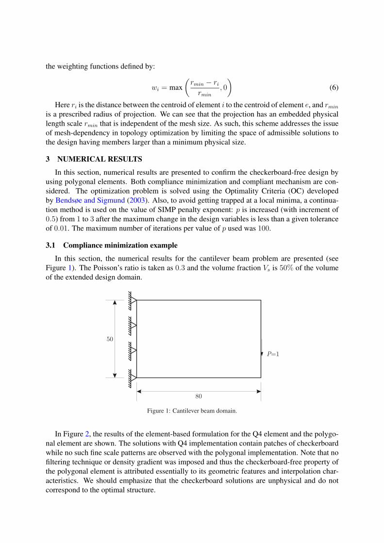
In this section, the numerical results for the cantilever beam problem are presented (seeFigure 1). The Poisson’s ratio is taken as 0.3 and the volume fraction Vs is 50% of the volumeof the extended design domain.
P=1
80
50
Figure 1: Cantilever beam domain.
In Figure 2, the results of the element-based formulation for the Q4 element and the polygo-nal element are shown. The solutions with Q4 implementation contain patches of checkerboardwhile no such fine scale patterns are observed with the polygonal implementation. Note that nofiltering technique or density gradient was imposed and thus the checkerboard-free property ofthe polygonal element is attributed essentially to its geometric features and interpolation char-acteristics. We should emphasize that the checkerboard solutions are unphysical and do notcorrespond to the optimal structure.
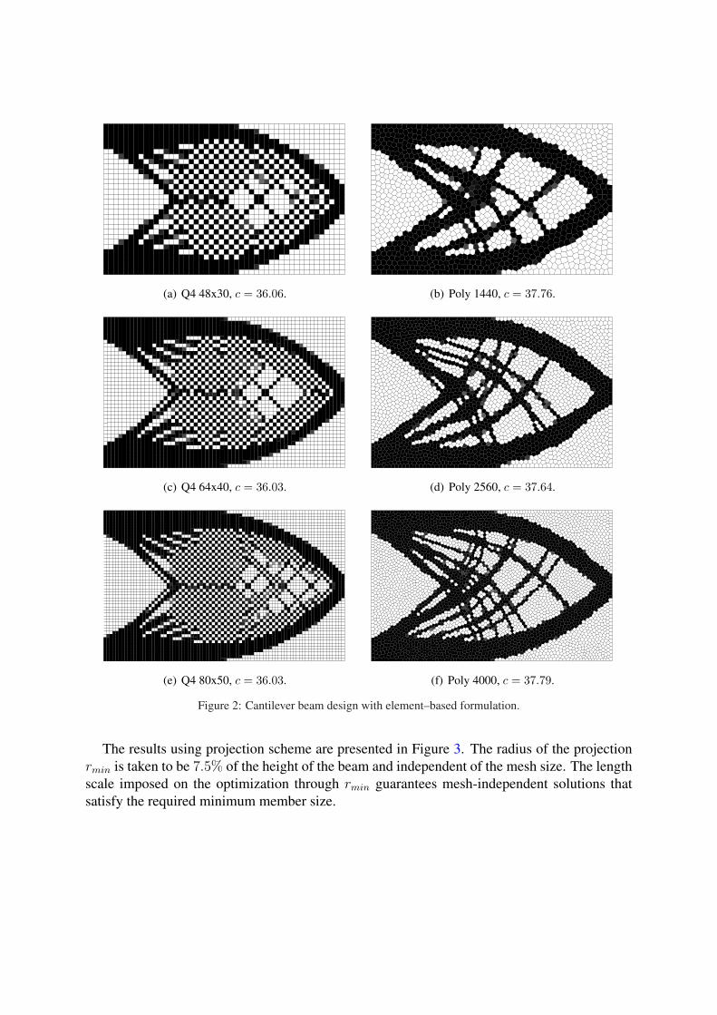
(a) Q4 48x30, c = 36.06. (b) Poly 1440, c = 37.76.
(c) Q4 64x40, c = 36.03. (d) Poly 2560, c = 37.64.
(e) Q4 80x50, c = 36.03. (f) Poly 4000, c = 37.79.
Figure 2: Cantilever beam design with element–based formulation.
The results using projection scheme are presented in Figure 3. The radius of the projectionrmin is taken to be 7.5% of the height of the beam and independent of the mesh size. The lengthscale imposed on the optimization through rmin guarantees mesh-independent solutions thatsatisfy the required minimum member size.
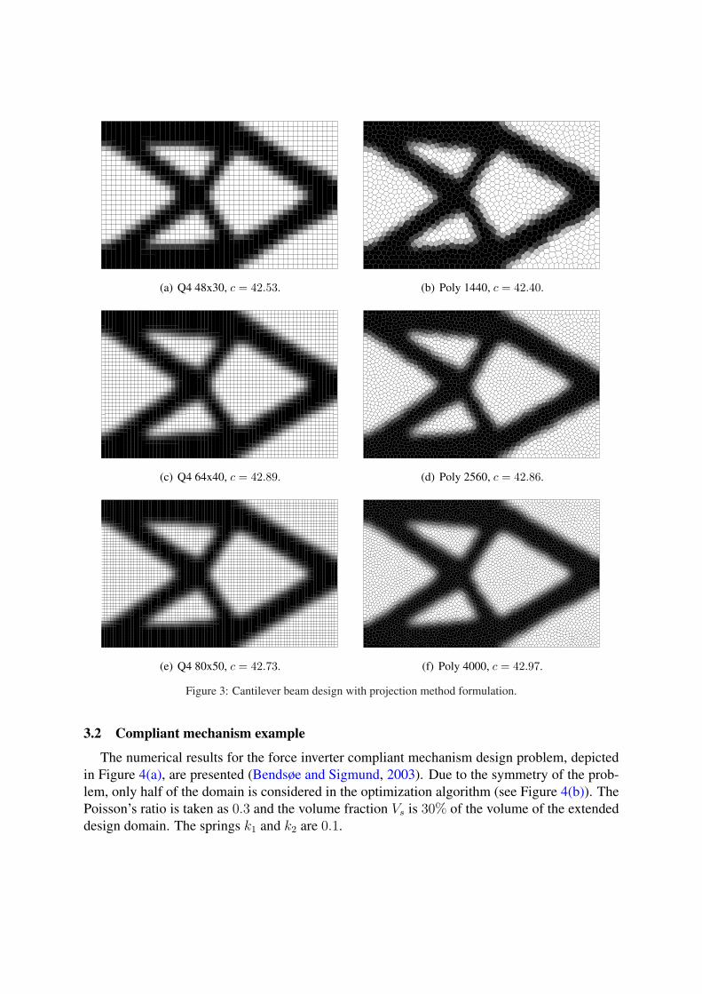
(a) Q4 48x30, c = 42.53. (b) Poly 1440, c = 42.40.
(c) Q4 64x40, c = 42.89. (d) Poly 2560, c = 42.86.
(e) Q4 80x50, c = 42.73. (f) Poly 4000, c = 42.97.
Figure 3: Cantilever beam design with projection method formulation.
3.2 Compliant mechanism example
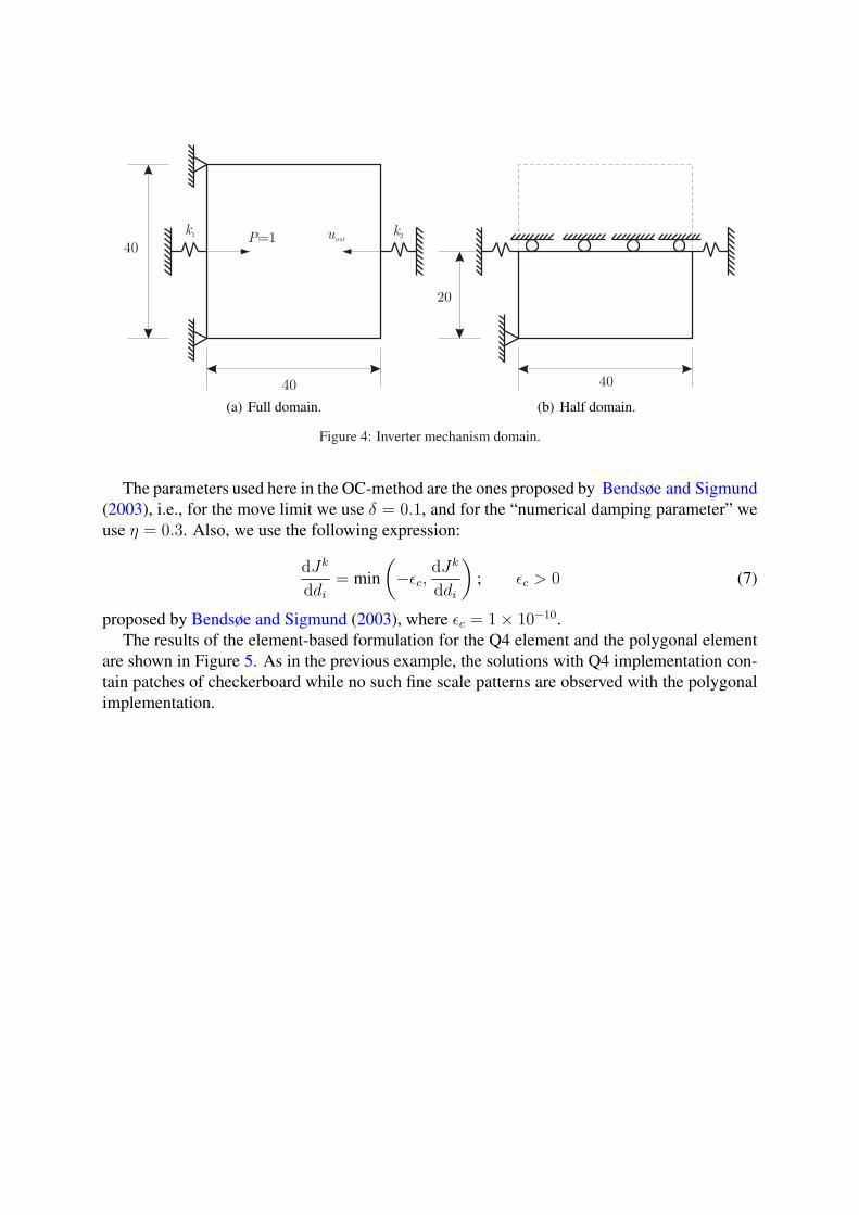
The numerical results for the force inverter compliant mechanism design problem, depictedin Figure 4(a), are presented (Bendsøe and Sigmund, 2003). Due to the symmetry of the prob-lem, only half of the domain is considered in the optimization algorithm (see Figure 4(b)). ThePoisson’s ratio is taken as 0.3 and the volume fraction Vs is 30% of the volume of the extendeddesign domain. The springs k1 and k2 are 0.1.
k2
k1
P=1 uout
40
40
(a) Full domain.
40
20
(b) Half domain.
Figure 4: Inverter mechanism domain.
The parameters used here in the OC-method are the ones proposed by Bendsøe and Sigmund(2003), i.e., for the move limit we use δ = 0.1, and for the “numerical damping parameter” weuse η = 0.3. Also, we use the following expression:
dJk
ddi
= min(−εc,
dJk
ddi
); εc > 0 (7)
proposed by Bendsøe and Sigmund (2003), where εc = 1× 10⁻¹⁰.The results of the element-based formulation for the Q4 element and the polygonal element
are shown in Figure 5. As in the previous example, the solutions with Q4 implementation con-tain patches of checkerboard while no such fine scale patterns are observed with the polygonalimplementation.
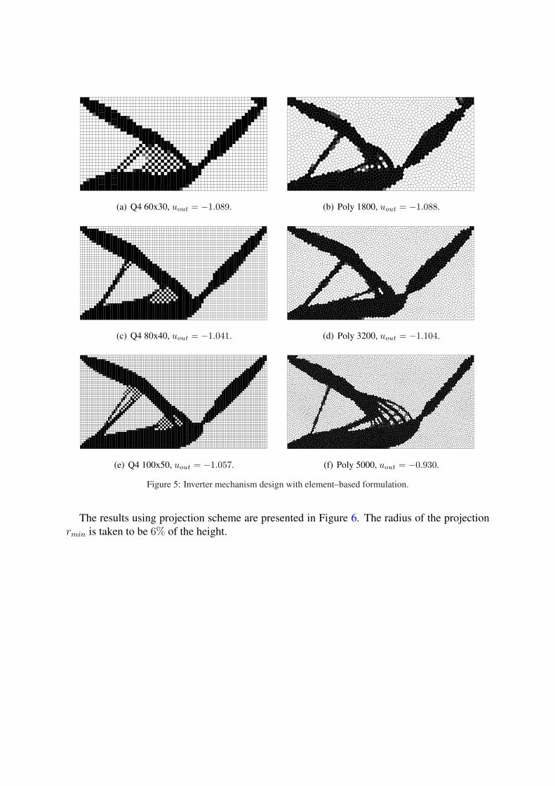
(a) Q4 60x30, uout = −1.089. (b) Poly 1800, uout = −1.088.
(c) Q4 80x40, uout = −1.041. (d) Poly 3200, uout = −1.104.
(e) Q4 100x50, uout = −1.057. (f) Poly 5000, uout = −0.930.
Figure 5: Inverter mechanism design with element–based formulation.
The results using projection scheme are presented in Figure 6. The radius of the projectionrmin is taken to be 6% of the height.
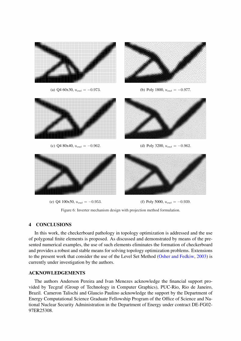
(a) Q4 60x30, uout = −0.973. (b) Poly 1800, uout = −0.977.
(c) Q4 80x40, uout = −0.962. (d) Poly 3200, uout = −0.962.
(e) Q4 100x50, uout = −0.953. (f) Poly 5000, uout = −0.939.
Figure 6: Inverter mechanism design with projection method formulation.
4 CONCLUSIONS
In this work, the checkerboard pathology in topology optimization is addressed and the useof polygonal finite elements is proposed. As discussed and demonstrated by means of the pre-sented numerical examples, the use of such elements eliminates the formation of checkerboardand provides a robust and stable means for solving topology optimization problems. Extensionsto the present work that consider the use of the Level Set Method (Osher and Fedkiw, 2003) iscurrently under investigation by the authors.
ACKNOWLEDGEMENTS
The authors Anderson Pereira and Ivan Menezes acknowledge the financial support pro-vided by Tecgraf (Group of Technology in Computer Graphics), PUC-Rio, Rio de Janeiro,Brazil. Cameron Talischi and Glaucio Paulino acknowledge the support by the Department ofEnergy Computational Science Graduate Fellowship Program of the Office of Science and Na-tional Nuclear Security Administration in the Department of Energy under contract DE-FG02-97ER25308.
REFERENCES
Bendsøe M. Optimal shape design as a material distribution problem. Structural Optimization,1(4):193–202, 1989.
Bendsøe M. and Sigmund O. Topology Optimization Theory, Methods and Applications. Berlin:Springer, 2003.
Diaz A. and Sigmund O. Checkerboard patterns in layout optimization. Structural Optimization,10:40–45, 1995.
Guest J., Prevost J., and Belytschko T. Achieving minimum length scale in topology opti-mization using nodal design variables and projection functions. International Journal forNumerical Methods in Engineering, 61(2):238–254, 2004.
Jang G., Jeong H., Kim Y., Sheen D., Park C., and Kim M. Checkerboard-free topology opti-mization using non–conforming finite elements. International Journal for Numerical Meth-ods in Engineering, 57(12):1717–1735, 2003.
Jog C. and Haber R. Stability of finite element models for distributed-parameter optimizationand topology design. Computer Methods in Applied Mechanics and Engineering, 130:203–226, 1996.
Osher S. and Fedkiw R. Level Set Methods and Dynamic Implicit Surfaces. Springer–Verlag,New York, 2003.
Sigmund O. and Petersson J. Numerical instabilities in topology optimization: A survey onprocedures dealing with checkerboard, mesh-dependence and local minima. Structural Opti-mization, 16:68–75, 1998.
Sukumar N. and Malsch E. Recent advances in the construction of polygonal finite elementinterpolants. Archives of Computational Methods in Engineering, 13(1):129–163, 2006.
Sukumar N. and Tabarraei A. Conforming polygonal finite elements. International Journal forNumerical Methods in Engineering, 61:2045–2066, 2004.
Talischi C., Paulino G.H., and Le C. Honeycomb wachspress finite elements for structuraltopology optimization. Structural and Multidisciplinary Optimization, 37(6):569–583, 2009.
Talischi C., Paulino G.H., Pereira A., and Menezes I.F.M. Polygonal finite elements for topol-ogy optimization: A unifying paradigm. International Journal for Numerical Methods inEngineering, 82(6):671–698, 2010.
Zhou M. and Rozvany G. The COC algorithm, Part II: Topological, geometry and generalizedshape optimization. Computer Methods in Applied Mechanics and Engineering, 89:197–224,1991.