
CILINDROS HIDRÁULICOS | HYDRAULIC...
24
CILINDROS HIDRÁULICOS | HYDRAULIC CYLINDERS CHF ISO 6022
Transcript of CILINDROS HIDRÁULICOS | HYDRAULIC...

CILINDROS HIDRÁULICOS | HYDRAULIC CYLINDERS
CHF ISO 6022

CILINDROS HIDRÁULICOS HYDRAULIC CYLINDERS
SERIE CHFISO 6022
13
ÍNDICE/ INDEX:
CODIFICACIÓN DE CILINDROS/ COMPOSITION OF CHF CYLINDER CODE
Características/Technical Features...…………………………………………………………………………….............2
Determinación del Cilindro/ Determination of the cylinder....…………………………………….……….…...3
Ejemplo de Cálculo/Example of Calculation………………………………………………………………………….....5
Designación Cilindros/Model code for CHS cylinders………………………………………...........................6
Descripción Materiales/Description of materials………………………………………………………………….…..7
Peso del cilindro/ Weight of the Cylinders and Accesories………………………………………..…………....8
TIPO FIJACIÓN CILINDROS / CHF SINGLE-ROD CYLINDERS MOUNTING TYPES
Brida Delantera/Front Round Flange Mounting…………………………………………..………………………...9
Brida Trasera/ Rear Round Flange Mounting……………… ………………………………………….……………10
Charnela con Rótula/ Spherical eye mounting…………… …..………………………………………………...…11
Charnela Macho/ Eye Mounting………………………………………………… ……………………………….…….…12
Fijación por Patas / Foot Mounting……………………………………………………………..………….……….…....13
Muñones Intermedios / Intermediate Trunnion Mounting……………………………………………...…....14
CILINDRO DOBLE VÁSTAGO / DOUBLE ROD CYLINDERS………………………………………………..…..…...15
CONEXIONES / PART TYPES……………………………………………………………………………………………....….16
ACCESORIOS / MOUNTING PARTS FOR HYDRAULIC CYLINDERS…………………………..…………..……17

SERIE CHF ISO 6022
CILINDROS HIDRÁULICOS
HYDRAULIC CYLINDERS
• CARACTERISTICAS • Norma ISO 6022 Tipo de construcción Con brida Presión nominal 250 bar Presión de prueba 375 bar Posición de montaje Indiferente
Temperatura ambiente -20ºC,,,+80ºC con estanqueidad tipo 1-3-8 -20ºC,,,+160ºC con estanqueidad vitón tipo 2-4-5
Temperatura del fluído -20ºC,,,+80ºC con estanqueidad tipo 1-3-8 -20ºC,,,+160ºC con estanqueidad vitón tipo 2-4-5
Fluído Aceite mineral - Otros fuídos bajo demanda Viscosidad 12,,,90 mm²/s Filtración Grado de filtración según NAS 1638 clase 9,,,10 a obtener con filtro ß25 =75 Estanqueidad vástago y pistón Ver codificación para pedido.Ø Pistón (mm) 050 063 080 100 125 140 160 180 200 250 320 Ø Vástago (mm) 32 36 40 45 50 56 63 70 80 90 90 100 100 110 110 125 125 140 160 180 200 220 Velocidad máxima (m/s) Juntas tipo1-3-5-4 0,5 0,4 0,25 0,2 Velocidad máxima (m/s) Juntas tipo 8-2 1 0,7 0,5 Longitud de amortiguación (mm)
Delantera 20 25 30 35 50 50 55 65 70 90 100 Trasera 20 25 30 35 50 50 55 65 70 90 100
. Tolerancia de carrera ISO 8135, ver página 20
• SPECIFICATIONS • Standar ISO 6022 Type Flange W orking pressure 250 bar Test pressure 375 bar Mounting position as desired
Ambient temperature -20ºC,,,+80ºC with seals type 1-3-8 -20ºC,,,+160ºC with viton seals type 2-4-5
Fluid temperature -20ºC,,,+80ºC with seals type 1-3-8 -20ºC,,,+160ºC with viton seals type 2-4-5
Fluid Mineral oil, other other on request Viscosity 12,,,90 mm²/s Filtration Oil contamination NAS 1638 class 9,,,10 to be met with filter ß25 =75 Rod and piston seals See ordering code.Ø Piston (mm) 050 063 080 100 125 140 160 180 200 250 320 Ø Rod (mm) 32 36 40 45 50 56 63 70 80 90 90 100 100 110 110 125 125 140 160 180 200 220 Max. Speed (m/s) seals 1-3-5-4 0,5 0,4 0,25 0,2 Max. Speed (m/s) seals 8-2 1 0,7 0,5 Cushioning length
Front 20 25 30 35 50 50 55 65 70 90 100 Rear 20 25 30 35 50 50 55 65 70 90 100
Stroke tolerance ISO 8135, see page 20
2 3HYLINDERS ®- Se reserva el derecho de modificar: Tecnica, material, cotas y formas sin previo aviso
HYLINDERS ®- Reserves the rights to modify: Techniques, materials, dimensions and shapes without prior notice.

SERIE CHF ISO 6022
CILINDROS HIDRÁULICOS
HYDRAULIC CYLINDERS
SECCIÓN, FUERZA, CAUDAL / SECTIONS, FORCES, DEBIT
Pistón
Vástago Relación secciones
AREAS
Empuje Fuerza Diferencial
Fuerza Tracción
Caudal Salida
Caudal Diferencial
Caudal Entrada
Bore
Rod Area ratio
Push Force Regen.
Force Pull
Flow Out
Flow Regeng.
Flow In
AL Ømm
MM Ømm
Ø A1/A3
S1
cm² S2
cm² S3
cm² F1
kN F2
kN F3
kN Q1
l/min Q2
l/min Q3
l/min
50 32 36
1,69 2,08
19,63 8,04 10,18
11,59 9,45
49,07 20,1 25,45
28,97 23,63
11,8 4,8 6,1
6,9 5,7
63 40 45
1,67 2,04
31,17 12,56 15,90
18,61 15,27
77,92 31,4 39,75
46,52 38,17
18,7 7,5 9,5
11,2 9,2
80 50 56
1,64 1,96
50,26 19,63 24,63
30,63 25,63
125,65 49,07 61,57
76,57 64,07
30,2 11,8 14,8
18,4 15,4
100 63 70
1,65 1,96
78,54 31,17 38,48
47,37 40,06
196,35 77,92 96,2
118,42 100,15
47,1 18,7 23,1
28,4 24
125 80 90
1,69 2,08
122,72 50,26 63,62
72,46 59,1
306,8 125,65 159,05
181,15 147,75
73,63 30,2 38,17
43,5 35,5
140 90 100
1,70 2,04
153,94 63,62 78,54
90,32 75,4
384,85 159,05 196,35
225,8 188,5
92,36 38,17 47,12
54,2 45,2
160 100 110
1,64 1,90
201,06 78,54 95,03
122,52 106
502,65 196,35 237,57
306,3 265
120,6 47,12 57
73,5 63,6
180 110 125
1,60 1,93
254,47 95,03 122,72
159,44 131,75
636,17 237,57 306,8
398,5 329,37
152,7 57 73,6
95,6 79
200 125 140
1,64 1,96
314,16 122,72 153,96
191,44 160,2
785,4 306,8 384,9
478,6 400,5
188,5 73,6 92,4
114,9 96,12
250 160 180
1,69 2,08
490,8 201,06 254,4
289,74 236,4
1227 502,65 636
474,3 591
294,5 120,6 152,6
173,8 141,8
320 200 220
1,64 1,90
804,2 314,16 380,1
490,04 424,1
2010,5 785,4 950,25
1225,1 1060,2
482,5 188,5 228,1
294 254,5
F1 S3 S1 S2
F3 F2
V3 V1 V2
FORMULAS EMPLEADAS / USED FORMULAE 2
F (kN ) A1 (cm ) p(bar )
Q (l / min) 6 v(m / s) S (cm2
) 1
100 1 1
2 2
F (kN ) A2 (cm ) p(bar ) Q2 (l / min) 6 v(m / s) S2 (cm )
2 100
Q (l / min) 6 v(m / s) S (cm
2 )
F3 (kN ) F1 (kN ) F2 (kN ) 3 3
Las fórmulas calculadas son teóricas, no se considera fricción. La velocidad empleada para el cálculo del caudal es de 0.1m/s y es una velocidad de ejemplo. The calculate force are theoretical. Friction has not been taken into account. The speed used for calculating the flow is 0.1m/s, which is just a sample speed.
33HYLINDERS ®- Se reserva el derecho de modificar: Tecnica, material, cotas y formas sin previo aviso
HYLINDERS ®- Reserves the rights to modify: Techniques, materials, dimensions and shapes without prior notice.
SERIE CHF ISO 6022
CILINDROS HIDRÁULICOS HYDRAULIC CYLINDERS
L
Car
ga F
T (K
p)
VLoa
d FT
(Kp)
L
L
L
L
L
L
L
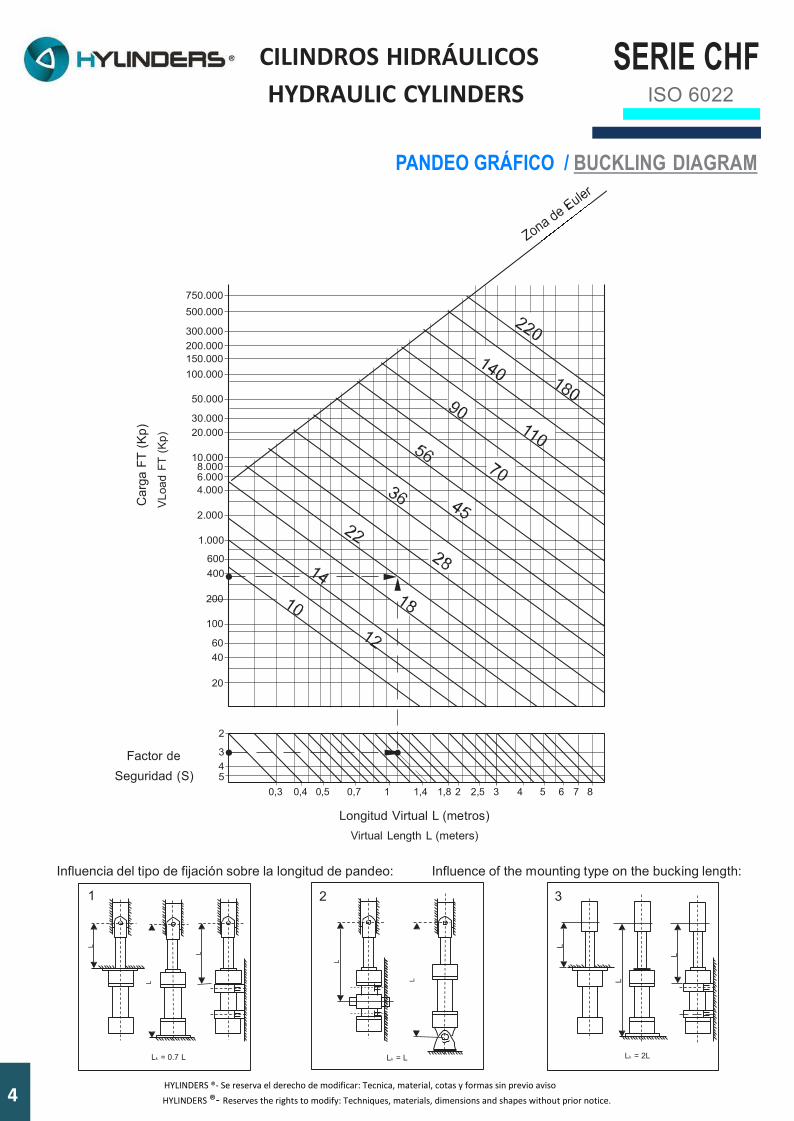
PANDEO GRÁFICO / BUCKLING DIAGRAM
750.000 500.000
300.000 200.000 150.000 100.000
50.000
30.000 20.000
10.000 8.000 6.000 4.000
2.000
1.000
600 400
200
100
60 40
20
2
Factor de 3 4
Seguridad (S) 5
0,3 0,4 0,5 0,7 1 1,4 1,8 2 2,5 3 4 5 6 7 8
Longitud Virtual L (metros) Virtual Length L (meters)
Influencia del tipo de fijación sobre la longitud de pandeo: Influence of the mounting type on the bucking length:
1 2 3
Lk = 0.7 L Lk = L Lk = 2L
4 3HYLINDERS ®- Se reserva el derecho de modificar: Tecnica, material, cotas y formas sin previo aviso HYLINDERS ®- Reserves the rights to modify: Techniques, materials, dimensions and shapes without prior notice.
2
CILINDROS HIDRÁULICOS HYDRAULIC CYLINDERS
SERIE CHF ISO 6022
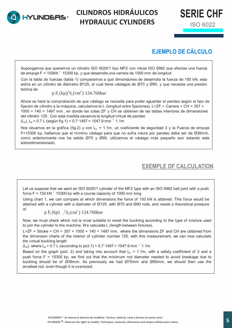
EJEMPLO DE CÁLCULO Supongamos que queremos un cilindro ISO 6020/1 tipo MF2 con rótula ISO 6982 que efectúe una fuerza de empuje F = 150kN ̃ 15300 kp, y que desarrolle una carrera de 1000 mm de longitud. Con la tabla de fuerzas (tabla 1) comparamos a que dimensiones de desarrolla la fuerza de 150 kN, esta estría en un cilindro de diámetro Ø125, el cual tiene vástagos de Ø70 y Ø90, y que necesita una presión teórica de
p F1 (kp) S1 (cm ) 124.766bar
Ahora se hará la comprobación de que vástago se necesita para poder aguantar el pandeo según el tipo de fijación de cilindro a la máquina, calculamos la L (longitud entre fijaciones), L=ZF + Carrera + CH = 357 + 1000 + 140 = 1497 mm , en donde las cotas ZF y CH se obtienen de las tablas interiores de dimensiones del cilindro 125 . Con esta medida sacamos la longitud virtual de pandeo (Lk), Lk = 0.7 L (según fig.1) = 0.7·1497 = 1047.9 mm ˜ 1.1m
Nos situamos en la gráfica (fig.2) y con Lk = 1.1m, un coeficiente de seguridad 3 y la Fuerza de empuje F=15300 kp, hallamos que el mínimo vástago para que no sufra rotura por pandeo debe ser de Ø36mm, como anteriormente nos ha salido Ø70 y Ø90, utilizamos el vástago más pequeño aun estando este sobredimensionado.
EXEMPLE OF CALCULATION
Let us suppose that we want an ISO 6020/1 cylinder of the MF2 type with an ISO 6982 ball joint with a push force F = 150 kN ˜ 15300 kp with a course capacity of 1000 mm long. Using chart 1, we can compare at which dimensions the force of 150 kN is attained. This force would be attained with a cylinder with a diameter of Ø125, with Ø70 and Ø90 rods, and needs a theoretical pressure of
2
p F1 (kp) S1 (cm
) 124.766bar
Now, we must check which rod is most suitable to resist the buckling according to the type of mixture used to join the cylinder to the machine. W e calculate L (length between fixtures), L=ZF + Stroke + CH = 357 + 1000 + 140 = 1497 mm, where the dimensions ZF and CH are obtained from the dimension charts of the interior of cylinder number 125. with this measurement, we can now calculate the virtual buckling length (Lk), where Lk = 0.7 L (according to pict.1) = 0.7·1497 = 1047.9 mm ˜ 1.1m Based on the graph (pict. 2) and taking into account that Lk = 1.1m, with a safety coefficient of 3 and a push force F = 15300 kp, we find out that the minimum rod diameter needed to avoid breakage due to buckling should be of Ø36mm. As previously we had Ø70mm and Ø90mm, we should then use the smallest rod, even though it is oversized.
53HYLINDERS ®- Se reserva el derecho de modificar: Tecnica, material, cotas y formas sin previo aviso
HYLINDERS ®- Reserves the rights to modify: Techniques, materials, dimensions and shapes without prior notice.

SERIE CHF
ISO 6022
CILINDROS HIDRÁULICOS HYDRAULIC CYLINDERS
DESIGNACIÓN CILINDROS CHF
CHF - 050/028 - S - A - 0500 - N - S - SM - 0 - A - 01
TIPO
PISTON
SERIE
POS. CONEXIÓN A
VASTAGO D B
S - Simple Vástago D - Doble Vástago
A- Es C
tandard
FIJACIÓN A- Brida delantera redonda (MF3) B- Brida trasera redonda (MF4) C- Brida delantera cuadrada (MF1) P- Brida trasera cuadrada (MF2) G- Charnela rótula (MP5) U- Charnela macho (MP3) E- Patas (MS2) F- Muñón intermedio (MT4)
LONG. CARRERA
AMORTIGUACIÓN N- Sin amortiguación V- Amort. Anterior Z- Amort. Posterior K- Amort. Doble
JUNTAS S- Estandard L- Baja fricción V- Vitón
DISTANCIADOR 0- Sin dinstanc. 1- Distan. 050 2- Distan.100 3- Distan. 150 4- Distan. 200 ROSCA VÁSTAGO SM- Estandard SP- Especial
MODEL CODE FOR CHF CYLINDERS
CHF - 050/028 - S - A - 0500 - N - S - SM - 0 - A - 01
TYPE
BORE
SERIES
CONECTION POS. A
ROD D B
S - Simple Rod D - Double Rod
ATTACHMENTS A-Front round flange (MF3) B- Rear round flange (Mf4) C- Front square flange (MF1) P- Front square flange (MF2) G- Ball jointed eye (MP5) U- Eye mounting (MP3) E- Feet (MS2) H- Intermediate trunnions (MT4)
STROKE
CUSHIONING N- Not cushioning V- Front only Z- Rear only K- Front and rear
SEALS S- Standard L- Low-friction V- Viton
C A- Standar
SPACER
0- Not spacer 1- Spacer 050 2- Spacer 100 3- Spacer 150 4- Spacer 200
PISTON ROD END
SM- Standard SP- Special
6 3HYLINDERS ®- Se reserva el derecho de modificar: Tecnica, material, cotas y formas sin previo aviso
HYLINDERS ®- Reserves the rights to modify: Techniques, materials, dimensions and shapes without prior notice.

CILINDROS HIDRÁULICOS HYDRAULIC CYLINDERS
01 Cylinder Housing 02 Rod 03 Rod Guiderings 04 Piston 05 Ear cylinder head 06 Flange 07 Forward Cylinder Head 08 Rear Cushioning 09 Forward Cushioning 10 Wiper ISO 6195 C - Type M-T
10A Wiper Viton ISO 6195 C - Type V 11 Rod Seal ISO 7425/2 - Type M-T
11A Rod Seal Viton ISO 7425/2 - Type V 12 Guide PTFE ISO 10766 13 O-Ring Seal + Supporting - Type M-T
13A O-Ring Seal + Supporting - Viton - Type V 14 O-Ring Seal - Type M-T
14A O-Ring Seal Viton - Type V 15 Guide PTFE ISO 10766 16 Piston Seal ISO 7425/1 - Type M-T
16A Piston Seal Viton ISO 7425/1 - Type V 17 O-Ring Seal - Type M-T
17A O-Ring Seal Viton - Type V 18 Cushion adjustment screw 19 Spring washer DIN 912 20 Screw stop pin DIN 913
01 Camisa 02 Vástago 03 Guía vástago 04 Pistón 05 Cabezal Trasero 06 Brida Fijación 07 Cabezal Delantero 08 Amortiguación Trasera 09 Amortiguación Delantera 10 Rascador ISO 6195 C - Tipo M-T
10A Rascador Viton ISO 6195 C - Tipo V 11 J. Vástago ISO 7425/2 - Tipo M-T (1)
11A J. Vástago Viton ISO 7425/2 - Tipo V (2) 12 Guia PTFE ISO 10766 13 Torica Guia + Aro Apoyo - Tipo M-T
13A Torica Guia + Aro Apoyo Viton - Tipo V 14 Junta Tórica - Tipo M-T
14A Junta Tórica Viton - Tipo V 15 Guia PTFE ISO 10766 16 Junta Piston ISO 7425/1 - Tipo M-T
16A Junta Piston Viton ISO 7425/1 - Tipo V 17 Junta Tórica Piston - Tipo M-T
17A Junta Tórica Piston Vitón - Tipo V 18 Regulador Amortiguación 19 Tornillo DIN 912 20 Prisionero DIN 913
2 3 7 6 1 15 4 6 20 5
16
16A
1813
13A
14
14A
17
17A
11
11A
10
10A
912 1915 14 8
DESCRIPCIÓN DESCRIPTION
SERIE CHF
ISO 6022
73HYLINDERS ®- Se reserva el derecho de modificar: Tecnica, material, cotas y formas sin previo aviso
HYLINDERS ®- Reserves the rights to modify: Techniques, materials, dimensions and shapes without prior notice.

SERIE CHF ISO 6022
CILINDROS HIDRÁULICOS HYDRAULIC CYLINDERS
ISO 6022
PESO DEL CILINDRO (kg) WEIGHT OF THE CYLINDERS AND ACCESORIES (kg)
PISTÓNBORE
VÁSTAGOROD
D - MP 3 S - MP 5
50 32 14,4 14,4 14 36 16 16 14
63 40 24 24 23 45 24 24 23
80 50 37 37 35 56 37 37 35
100 63 57 57 55 70 58 58 55
125 80 99 99 99 90 100 100 100
140 90 148 148 149
100 149 149 150
160 100 191 191 195 110 192 192 196
180 110 271 271 273 125 272 272 274
200 125 344 344 363 140 346 346 365
250 160 641 641 692 180 642 642 694
PISTÓNBORE
VÁSTAGOROD
E - MS 2 L - MT 4 Suplemento cada 100mm de carreraAdditional weightper 100mm stroke
Cabeza de rótulaRod eye with
spherical bearing
50 32 14 14 1,9 1,2 36 15 14 2,2 1,2
63 40 22 23 3,2 2,1 45 22 23 3,4 2,1
80 50 35 35 4,9 4,4 56 36 35 5,2 4,4
100 63 55 56 6,8 7,6 70 56 56 7,8 7,6
125 80 96 102 10,8 14,5 90 97 102 12,1 14,5
140 90 147 154 13,4 17 100 148 155 14,8 17
160 100 197 200 17,4 28 110 198 201 19,2 28
180 110 274 278 21,2 32 125 276 279 24,3 32
200 125 349 356 25,3 43 140 351 358 28,6 43
250 160 608 380 34,2 80 180 614 681 38,8 80
A - MF 3 B - MF 4
8 3HYLINDERS ®- Se reserva el derecho de modificar: Tecnica, material, cotas y formas sin previo aviso HYLINDERS ®- Reserves the rights to modify: Techniques, materials, dimensions and shapes without prior notice.
SERIE CHF ISO 6022
CILINDROS HIDRÁULICOS HYDRAULIC CYLINDERS
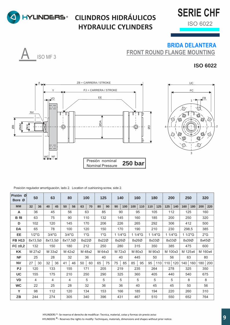
A ISO MF 3
BRIDA DELANTERA FRONT ROUND FLANGE MOUNTING
ISO 6022
Presión nominal Nominal Pressure
250 bar
Posición regulador amortiguación, lado 2. Location of cushioning-screw, side 2.
Pistón Ø
Bore Ø
50
63
80
100
125
140
160
180
200
250
320
MM 32 36 40 45 50 56 63 70 80 90 90 100 100 110 110 125 125 140 160 180 200 220
A 36 45 56 63 85 90 95 105 112 125 160 B f8 63 75 90 110 132 145 160 185 200 250 320
D 102 120 145 170 206 226 265 292 306 412 500 DA 65 78 100 120 150 170 190 210 230 298,5 385 EE 1/2"G 3/4"G 3/4"G 1"G 1"G 1 1/4"G 1 1/4"G 1 1/4"G 1 1/4"G 1 1/2"G 2"G
FB H13 8x13,5Ø 8x13,5Ø 8x17,5Ø 8x22Ø 8x22Ø 8x26Ø 8x26Ø 8x33Ø 8x33Ø 8x39Ø 8x45Ø FC ±0,2 132 150 180 212 250 280 315 350 385 475 600
KK M 27x2 M 33x2 M 42x2 M 48x2 M 64x3 M 72x3 M 80x3 M 90x3 M 100x3 M 125x4 M 160x4 NF 25 28 32 36 40 40 445 50 56 63 80 NV 27 30 32 36 41 46 50 60 65 75 75 85 85 95 95 110 110 120 140 160 180 200 PJ 120 133 155 171 205 219 235 264 278 325 350 UC 155 175 210 250 290 325 360 405 440 540 675 VD 4 4 4 5 5 5 5 5 5 8 8 WC 22 25 28 32 36 36 40 45 45 50 56
Y 98 112 120 134 153 166 185 194 220 260 310 ZB 244 274 305 340 396 431 467 510 550 652 764
4
3
2
1
KØ
K
ØM
M
ØB
NV
A
Y
ZB + CARRERA / STROKE
PJ + CARRERA / STROKE
EEVD
WC NF
ØD
A
ØD
UC
FC
FB
93HYLINDERS ®- Se reserva el derecho de modificar: Tecnica, material, cotas y formas sin previo aviso
HYLINDERS ®- Reserves the rights to modify: Techniques, materials, dimensions and shapes without prior notice.

SERIE CHF ISO 6022
CILINDROS HIDRÁULICOS HYDRAULIC CYLINDERS
B ISO MF 4
BRIDA TRASERA REAR ROUND FLANGE MOUNTING
ISO 6022
Presión nominal Nominal Pressure
250 bar
Posición regulador amortiguación, lado 2. Location of cushioning-screw, side 2.
Pistón Ø
Bore Ø
50
63
80
100
125
140
160
180
200
250
320
MM 32 36 40 45 50 56 63 70 80 90 90 100 100 110 110 125 125 140 160 180 200 220
A 36 45 56 63 85 90 95 105 112 125 160 B 63 75 90 110 132 145 160 185 200 250 320
BA H8 63 75 90 110 132 145 160 185 200 250 320 D 102 120 145 170 206 226 265 292 306 412 500
DA 65 78 100 120 150 170 190 210 230 298,5 385 EE 1/2"G 3/4"G 3/4"G 1"G 1"G 1 1/4"G 1 1/4"G 1 1/4"G 1 1/4"G 1 1/2"G 2"G
FB H13 8x13,5Ø 8x13,5Ø 8x17,5Ø 8x22Ø 8x22Ø 8x26Ø 8x26Ø 8x33Ø 8x33Ø 8x39Ø 8x45Ø FC ±0,2 132 150 180 212 250 280 315 350 385 475 600
KK M 27x2 M 33x2 M 42x2 M 48x2 M 64x3 M 72x3 M 80x3 M 90x3 M 100x3 M 125x4 M 160x4 NF 25 28 32 36 40 40 45 50 56 63 80 NV 27 30 32 36 41 46 50 60 65 75 75 85 85 95 95 110 110 120 140 160 180 200 PJ 120 133 155 171 205 219 235 264 278 325 350 UC 155 175 210 250 290 325 360 405 440 540 675 VA 4 4 5 5 6 6 7 10 10 12 14 VD 4 4 4 5 5 5 5 5 5 8 8 VE 29 32 36 41 45 45 50 55 61 71 88 WF 47 53 60 68 76 76 85 95 101 113 136
Y 98 112 120 134 153 166 185 194 220 260 310 ZP 265 298 332 371 430 465 505 550 596 703 830
4
3
2
1
UC
FC
FB
KØ
K
ØM
M
ØB
NV
A
Y
ZP + CARRERA / STROKE
PJ + CARRERA / STROKE
EE
VE
ØA
D
ØA
B
ØD
WF VA
NF
VD
10 3HYLINDERS ®- Se reserva el derecho de modificar: Tecnica, material, cotas y formas sin previo aviso
HYLINDERS ®- Reserves the rights to modify: Techniques, materials, dimensions and shapes without prior notice.

SERIE CHF ISO 6022
CILINDROS HIDRÁULICOS HYDRAULIC CYLINDERS
G ISO MP 5
CHARNELA CON RÓTULA SPHERICAL EYE MOUNTING
ISO 6022
Presión nominal Nominal Pressure 250 bar
Posición regulador amortiguación, lado 2. Location of cushioning-screw, side 2.
Pistón Ø
Bore Ø
50
63
80
100
125
140
160
180
200
250
320
MM 32 36 40 45 50 56 63 70 80 90 90 100 100 110 110 125 125 140 160 180 200 220
A 36 45 56 63 85 90 95 105 112 125 160 B 63 75 90 110 132 145 160 185 200 250 320 CX 32 +0,025 40 +0,025 50 +0,025 63 +0,030 80 +0,030 90 +0,035 100 +0,035 110 +0,035 125 +0,040 160 +0,040 200 +0,046
D 102 120 145 170 206 226 265 292 306 412 500 DA 65 78 100 120 150 170 190 210 230 298,5 385 EE 1/2"G 3/4"G 3/4"G 1"G 1"G 1 1/4"G 1 1/4"G 1 1/4"G 1 1/4"G 1 1/2"G 2"G EP 27 32 40 52 66 72 84 88 102 130 162 EX 32 -0,025 40 -0,025 50 -0,025 63 -0,030 80 -0,030 90 -0,035 100 -0,035 110 -0,035 125 -0,040 160 -0,040 200 -0,046
KK M 27x2 M 33x2 M 42x2 M 48x2 M 64x3 M 72x3 M 80x3 M 90x3 M 100x3 M 125x4 M 160x4 LT 61 74 90 102 124 149 150 180 206 251 316 MS 40 50 63 71 90 101 112 129 145 200 250 NV 27 30 32 36 41 46 50 60 65 75 75 85 85 95 95 110 110 120 140 160 180 200 PJ 120 133 155 171 205 219 235 264 278 325 350 VD 4 4 4 5 5 5 5 5 5 8 8 VE 29 32 36 41 45 45 50 55 61 71 88 WF 47 53 60 68 76 76 85 95 101 113 136 XO 305 348 395 442 520 580 617 690 756 903 1080 Y 98 112 120 134 153 166 185 194 220 260 310
ØK
K
ØM
MØB
NV
A
Y
XO + CARRERA / STROKE
PJ + CARRERA / STROKE
EE
ØD
A
ØD
MS
DIN 71412
VD
VE
WF
LT
2
3
4
1
EP
EX
ØC
X
4º
4º
11HYLINDERS ®- Se reserva el derecho de modificar: Tecnica, material, cotas y formas sin previo aviso
HYLINDERS ®- Reserves the rights to modify: Techniques, materials, dimensions and shapes without prior notice.
SERIE CHF ISO 6022
CILINDROS HIDRÁULICOS HYDRAULIC CYLINDERS
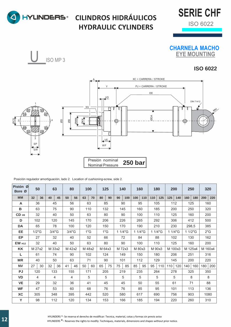
U ISO MP 3
ØC
D
ØD
ØB
ØM
M
ØK
K
ØD
A
CHARNELA MACHO EYE MOUNTING
ISO 6022
A XC + CARRERA / STROKE
Y PJ + CARRERA / STROKE
EE
VD DIN 71412
1 NV
2 4
3 VE EP WF
EW
Presión nominal Nominal Pressure 250 bar
Posición regulador amortiguación, lado 2. Location of cushioning-screw, side 2.
Pistón ØBore Ø
50
63
80
100
125
140
160
180
200
250
320
MM 32 36 40 45 50 56 63 70 80 90 90 100 100 110 110 125 125 140 160 180 200 220
A 36 45 56 63 85 90 95 105 112 125 160 B 63 75 90 110 132 145 160 185 200 250 320
CD H9 32 40 50 63 80 90 100 110 125 160 200 D 102 120 145 170 206 226 265 292 306 412 500
DA 65 78 100 120 150 170 190 210 230 298,5 385 EE 1/2"G 3/4"G 3/4"G 1"G 1"G 1 1/4"G 1 1/4"G 1 1/4"G 1 1/4"G 1 1/2"G 2"G EP 27 32 40 52 66 72 84 88 102 130 162
EW H12 32 40 50 63 80 90 100 110 125 160 200 KK M 27x2 M 33x2 M 42x2 M 48x2 M 64x3 M 72x3 M 80x3 M 90x3 M 100x3 M 125x4 M 160x4 L 61 74 90 102 124 149 150 180 206 251 316
MR 40 50 63 71 90 101 112 129 145 200 220 NV 27 30 32 36 41 46 50 60 65 75 75 85 85 95 95 110 110 120 140 160 180 200 PJ 120 133 155 171 205 219 235 264 278 325 350 VD 4 4 4 5 5 5 5 5 5 8 8 VE 29 32 36 41 45 45 50 55 61 71 88 WF 47 53 60 68 76 76 85 95 101 113 136 XC 305 348 395 442 520 580 617 690 756 903 1080 Y 98 112 120 134 153 166 185 194 220 260 310
12 3HYLINDERS ®- Se reserva el derecho de modificar: Tecnica, material, cotas y formas sin previo aviso HYLINDERS ®- Reserves the rights to modify: Techniques, materials, dimensions and shapes without prior notice.
SERIE CHF ISO 6022
CILINDROS HIDRÁULICOS HYDRAULIC CYLINDERS
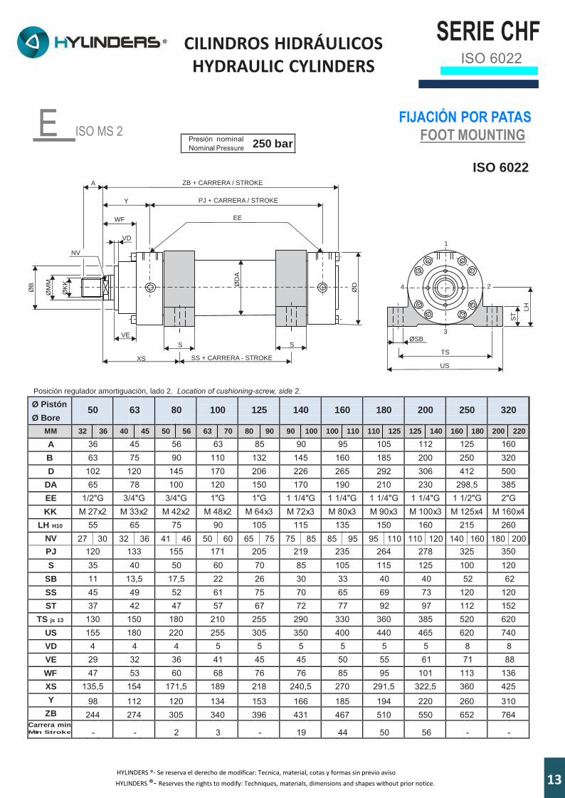
E ISO MS 2 FIJACIÓN POR PATAS
FOOT MOUNTING
ISO 6022
Ø Pistón Ø Bore
50
63
80
100
125
140
160
180
200
250
320
MM 32 36 40 45 50 56 63 70 80 90 90 100 100 110 110 125 125 140 160 180 200 220
A 36 45 56 63 85 90 95 105 112 125 160 B 63 75 90 110 132 145 160 185 200 250 320 D 102 120 145 170 206 226 265 292 306 412 500
DA 65 78 100 120 150 170 190 210 230 298,5 385 EE 1/2"G 3/4"G 3/4"G 1"G 1"G 1 1/4"G 1 1/4"G 1 1/4"G 1 1/4"G 1 1/2"G 2"G KK M 27x2 M 33x2 M 42x2 M 48x2 M 64x3 M 72x3 M 80x3 M 90x3 M 100x3 M 125x4 M 160x4
LH H10 55 65 75 90 105 115 135 150 160 215 260 NV 27 30 32 36 41 46 50 60 65 75 75 85 85 95 95 110 110 120 140 160 180 200 PJ 120 133 155 171 205 219 235 264 278 325 350 S 35 40 50 60 70 85 105 115 125 100 120
SB 11 13,5 17,5 22 26 30 33 40 40 52 62 SS 45 49 52 61 75 70 65 69 73 120 120 ST 37 42 47 57 67 72 77 92 97 112 152
TS js 13 130 150 180 210 255 290 330 360 385 520 620 US 155 180 220 255 305 350 400 440 465 620 740 VD 4 4 4 5 5 5 5 5 5 8 8 VE 29 32 36 41 45 45 50 55 61 71 88 WF 47 53 60 68 76 76 85 95 101 113 136 XS 135,5 154 171,5 189 218 240,5 270 291,5 322,5 360 425 Y 98 112 120 134 153 166 185 194 220 260 310
ZB 244 274 305 340 396 431 467 510 550 652 764 Carrera min Min Strok e
-
-
2
3
-
19
44
50
56
-
-
KØ
K
ØM
M
ØB
NV
A
Y
ZB + CARRERA / STROKE
PJ + CARRERA / STROKE
EE
VD
VE
ØD
A
S S
XS SS + CARRERA - STROKEØ
D
WF
4
3
2
1
ØSB
TS
US
ST
HL
Posición regulador amortiguación, lado 2. Location of cushioning-screw, side 2.
Presión nominal Nominal Pressure 250 bar
133HYLINDERS ®- Se reserva el derecho de modificar: Tecnica, material, cotas y formas sin previo aviso
HYLINDERS ®- Reserves the rights to modify: Techniques, materials, dimensions and shapes without prior notice.

SERIE CHF ISO 6022
CILINDROS HIDRÁULICOS HYDRAULIC CYLINDERS
ØTD
F ISO MT 4 MUÑONES INTERMEDIOS
INTERMEDIATE TRUNNION MOUNTING
ISO 6022
1
R1
4
3
TL TM TL
UM
Posición regulador amortiguación, lado 2. Location of cushioning-screw, side 2.
Pistón ØBore Ø
50
63
80
100
125
140
160
180
200
250
320
MM 32 36 40 45 50 56 63 70 80 90 90 100 100 110 110 125 125 140 160 180 200 220
A 36 45 56 63 85 90 95 105 112 125 160 B 63 75 90 110 132 145 160 185 200 250 320 BD 38 48 58 78 98 118 128 138 178 180 220 D 102 120 145 170 206 226 265 292 306 412 500
DA 65 78 100 120 150 170 190 210 244,5 298,5 385 EE 1/2"G 3/4"G 3/4"G 1"G 1"G 1 1/4"G 1 1/4"G 1 1/4"G 1 1/4"G 1 1/2"G 2"G KK M 27x2 M 33x2 M 42x2 M 48x2 M 64x3 M 72x3 M 80x3 M 90x3 M 100x3 M 125x4 M 160x4 NV 27 30 32 36 41 46 50 60 65 75 75 85 85 95 95 110 110 120 140 160 180 200 PJ 120 133 155 171 205 219 235 264 278 325 350 R1 2 2,5 2,5 3 3 3 3,5 3,5 3,5 3,5 4
TD f8 32 40 50 63 80 90 100 110 125 160 200 TL 25 32 40 50 63 70 80 90 100 125 160
TM h12 112 125 150 180 224 265 280 320 335 425 530 UM 162 189 230 280 350 405 440 500 535 675 850 VD 4 4 4 5 5 5 5 5 5 8 8 VE 29 32 36 41 45 45 50 55 61 71 88 WF 47 53 60 68 76 76 85 95 101 113 136
XV min 174 202 226,5 259 301 336 373,5 405 461 520 625 XV max 151 167 180,5 195 225 230 251,5 267 277 320 345
Y 98 112 120 134 153 166 185 194 220 260 310 ZB 244 274 305 340 396 431 467 510 550 652 764
Carreramin Min Stroke 23 35 46 64 76 106 122 138 184 200 280
ØK
K
ØM
MØB
NV
A
Y
ZB + CARRERA / STROKE
PJ + CARRERA / STROKE
EE
ØD
A
WF
ØD
VD
BD
XV + CARRERA - STROKE
VE
Presión nominal Nominal Pressure 250 bar
14 3HYLINDERS ®- Se reserva el derecho de modificar: Tecnica, material, cotas y formas sin previo aviso HYLINDERS ®- Reserves the rights to modify: Techniques, materials, dimensions and shapes without prior notice.
SERIE CHF ISO 6022
CILINDROS HIDRÁULICOS HYDRAULIC CYLINDERS
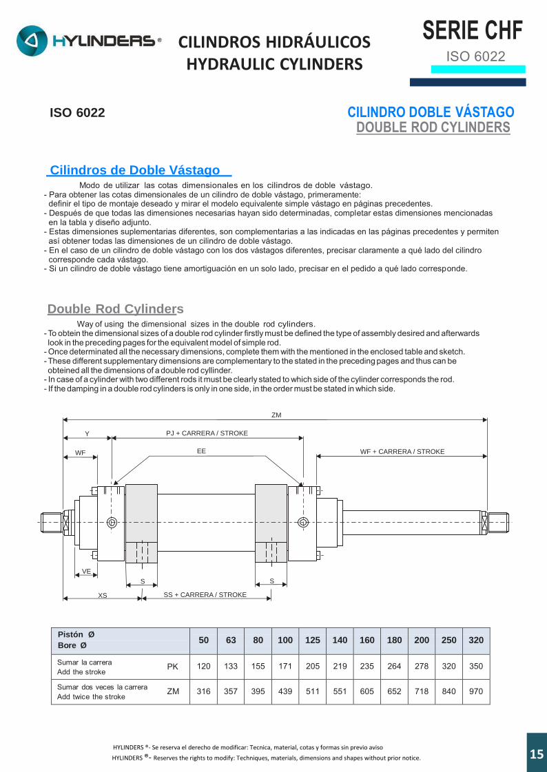
ISO 6022 CILINDRO DOBLE VÁSTAGO DOUBLE ROD CYLINDERS
Cilindros de Doble Vástago Modo de utilizar las cotas dimensionales en los cilindros de doble vástago.
- Para obtener las cotas dimensionales de un cilindro de doble vástago, primeramente: definir el tipo de montaje deseado y mirar el modelo equivalente simple vástago en páginas precedentes.
- Después de que todas las dimensiones necesarias hayan sido determinadas, completar estas dimensiones mencionadas en la tabla y diseño adjunto.
- Estas dimensiones suplementarias diferentes, son complementarias a las indicadas en las páginas precedentes y permiten así obtener todas las dimensiones de un cilindro de doble vástago.
- En el caso de un cilindro de doble vástago con los dos vástagos diferentes, precisar claramente a qué lado del cilindro corresponde cada vástago.
- Si un cilindro de doble vástago tiene amortiguación en un solo lado, precisar en el pedido a qué lado corresponde.
Double Rod Cylinders Way of using the dimensional sizes in the double rod cylinders.
- To obtein the dimensional sizes of a double rod cylinder firstly must be defined the type of assembly desired and afterwards look in the preceding pages for the equivalent model of simple rod.
- Once determinated all the necessary dimensions, complete them with the mentioned in the enclosed table and sketch. - These different supplementary dimensions are complementary to the stated in the preceding pages and thus can be obteined all the dimensions of a double rod cyllinder.
- In case of a cylinder with two different rods it must be clearly stated to which side of the cylinder corresponds the rod. - If the damping in a double rod cylinders is only in one side, in the order must be stated in which side.
Pistón Ø
Bore Ø
50
63
80
100
125
140
160
180
200
250
320
Sumar la carrera PK Add the stroke
120
133
155
171
205
219
235
264
278
320
350
Sumar dos veces la carrera ZM Add twice the stroke
316
357
395
439
511
551
605
652
718
840
970
Y
ZM
PJ + CARRERA / STROKE
EE
VE
S S
XS SS + CARRERA / STROKE
WF WF + CARRERA / STROKE
153HYLINDERS ®- Se reserva el derecho de modificar: Tecnica, material, cotas y formas sin previo aviso
HYLINDERS ®- Reserves the rights to modify: Techniques, materials, dimensions and shapes without prior notice.
SERIE CHF ISO 6022
CILINDROS HIDRÁULICOS HYDRAULIC CYLINDERS
EA
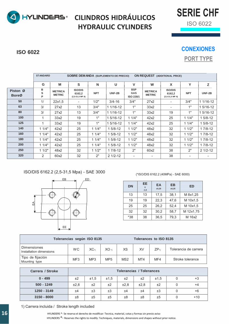
ISO 6022 CONEXIONES
PORT TYPE
ST ANDARD SOBRE DEM ANDA (SUPLEMENTO DE PRECIO) ON REQUEST (ADDITIONAL PRICE)
G M S N U V W X Y Z
Piston Ø
BoreØ
B
S
P
METRICA
METRIC
ISO/DIS 6162,2
(2,5-31,5 MP A) NPT UNF-2B
BSP
GAS ISO 228/1
METRICA
METRIC
ISO/DIS 6162,2
(2,5-31,5 MP A) NPT UNF-2B
50 1/ 22x1,5 - 1/2" 3/4-16 3/4" 27x2 - 3/4" 1 1/16-12 63 3/ 27x2 13 3/4" 1 1/16-12 1" 33x2 - 1" 1 5/16-12 80 3/ 27x2 13 3/4" 1 1/16-12 1" 33x2 19 1" 1 5/16-12 100 1 33x2 19 1" 1 5/16-12 1 1/4" 42x2 25 1 1/4" 1 5/8-12 125 1 33x2 19 1" 1 5/16-12 1 1/4" 42x2 25 1 1/4" 1 5/8-12 140 1 1/4" 42x2 25 1 1/4" 1 5/8-12 1 1/2" 48x2 32 1 1/2" 1 7/8-12 160 1 1/4" 42x2 25 1 1/4" 1 5/8-12 1 1/2" 48x2 32 1 1/2" 1 7/8-12 180 1 1/4" 42x2 25 1 1/4" 1 5/8-12 1 1/2" 48x2 32 1 1/2" 1 7/8-12 200 1 1/4" 42x2 25 1 1/4" 1 5/8-12 1 1/2" 48x2 32 1 1/2" 1 7/8-12 250 1 1/2" 48x2 32 1 1/2" 1 7/8-12 2" 60x2 38 2" 2 1/2-12 320 2 60x2 32 2" 2 1/2-12 - - 38 - -
ISO/DIS 6162.2 (2,5-31,5 Mpa) - SAE 3000
EB ED
(*ISO/DIS 6162.2 (40MPa) - SAE 6000)
DN
EE 0
-1,5
EA ±0,25
EB ±0,25
ED
13 13 17,5 38,1 M 8x1,25 19 19 22,3 47,6 M 10x1,5 25 25 26,2 52,4 M 10x1,5 32 32 30,2 58,7 M 12x1,75 *38 38 36,5 79,3 M 16x2
EE
Tolerancias según ISO 8135 Tolerances to ISO 8135
Dimensiones Installation dimensions
W C
XC1)
XO 1)
XS
XV
ZP1)
Tolerancia de carrera
Tipo de fijación Mounting type
MF3
MP3
MP5
MS2
MT4
MF4
Stroke tolerance
Carrera / Stroke Tolerancias / Tolerances
0 - 499 ±2 ±1,5 ±1,5 ±2 ±2 ±1,5 0 +3
500 - 1249 ±2,8 ±2 ±2 ±2,8 ±2,8 ±2 0 +4
1250 - 3149 ±4 ±3 ±3 ±4 ±4 ±3 0 +6
3150 - 8000 ±8 ±5 ±5 ±8 ±8 ±5 0 +10
1) Carrera incluida / Stroke length included
16 163HYLINDERS ®- Se reserva el derecho de modificar: Tecnica, material, cotas y formas sin previo aviso
HYLINDERS ®- Reserves the rights to modify: Techniques, materials, dimensions and shapes without prior notice.
SERIE CH ISO 6022
CILINDROS HIDRÁULICOS HYDRAULIC CYLINDERS
FL
UK
K
C
RF
ØC
K
LE
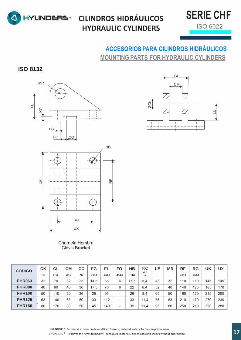
ISO 8132
ACCESORIOS PARA CILINDROS HIDRÁULICOS
MOUNTING PARTS FOR HYDRAULIC CYLINDERS
CL
CM
MR
FG
FO CO
HB
RG
UX
Charnela Hembra
Clevis Bracket
CODIGO CK
H9
CL
H16
CM
A12
CO
N9
FG
Js14
FL
Js12
FO
Js14
HB
H13
KC +0,3
0
LE MR RF
Js14
RG
Js14
UK UX
FHR063 32 70 32 25 14,5 65 6 17,5 5,4 43 32 110 110 145 145
FHR080 40 90 40 36 17,5 76 6 22 8,4 52 40 140 125 185 170
FHR100 50 110 50 36 25 95 - 26 8,4 65 50 165 150 215 200
FHR125 63 140 63 50 33 112 - 33 11,4 75 63 210 170 270 230
FHR160 80 170 80 50 45 140 - 39 11,4 95 80 250 210 320 280
F
173HYLINDERS ®- Se reserva el derecho de modificar: Tecnica, material, cotas y formas sin previo aviso
HYLINDERS ®- Reserves the rights to modify: Techniques, materials, dimensions and shapes without prior notice.
CILINDROS HIDRÁULICOS HYDRAULIC CYLINDERS
ALMACENAJE Y MANTENIMIENTO
Para garantizar una vida larga a los cilindros, HYLINDERS recomienda seguir cuidadosamente las siguientes reglas de mantenimiento:
Almacenar los cilindros en un ambiente cerrado, seco, en posición vertical con el vástago hacia arriba para reducir la posibilidad de producirse corrosión interna debido a la condensación.
Los vástagos, las roscas, los centrajes y todos los accesorios aplicados al vástago y a la cabeza deben protegerse no sólo de los agentes agresivos sino también de los golpes que pueden comprometer su funcionalidad.
Los tapones de protección montadas en las conexiones no deben ser quitadas hasta que no se instale el cilindro,
para prevenir la introducción de suciedad y cuerpos extraños en el mismo.
Después de la instalación, el cilindro debe verificarse periódicamente para asegurarse que no hay pérdidas de aceite debido al uso de las juntas o eventuales daños a las partes mecánicas. Si hay, se deben reemplazar las juntas lo más pronto posible.
En funcionamiento, asegúrese que el vástago no gira alrededor de su propio eje. En el caso en el que la rotación
es necesaria, quitar presión de alimentación y se puede seguir con la operación.
Los kits de juntas suministrados por HYLINDERS y también las piezas de repuesto deben almacenarse en un ambiente seco, evitando el contacto directo con fuentes de calor o la exposición directa a la luz del sol.
STORAGE AND MAINTENANCE
To guarantee the cylinders a long life, HYLINDERS recommends you follow the following maintenance rules extremely
carefully: Store the cylinders in a closed, dry environment in a vertical position with the rod pointing upwards to reduce the
chance of corrosion taking place inside due to condensation.
The rod, screw threads, centres and all the accessories applied to the rod and cap must be protected not only from aggressive agents but also from knocks which could compromise their proper working.
The protective caps fitted on the connections must not be removed until the time of installation in order to prevent dirt
and/or foreign bodies from entering the cylinder.
After installation, periodically check the cylinder to make sure there are no traces of oil due to the seals wearing out or any damage to mechanical parts. If there are, provide for their replacement as soon as possible.
When in function, make sure the rod does not rotate around its own axis. In the event that rotation becomes
necessary, remove supply pressure and proceed with the operation.
The seals kits supplied by HYLINDERS as well as spare parts must be stocked in a dry environment and direct contact with sources of heat and direct exposure to sunlight must be avoided.
18
SERIE CHFISO 6022
183HYLINDERS ®- Se reserva el derecho de modificar: Tecnica, material, cotas y formas sin previo aviso
HYLINDERS ®- Reserves the rights to modify: Techniques, materials, dimensions and shapes without prior notice.

CILINDROS HIDRÁULICOS HYDRAULIC CYLINDERS
NOTAS / NOTES:
SERIE CHISO 6022
F
193

SERIE CHS
ISO 3320
CILINDROS HIDRÁULICOS HYDRAULIC CYLINDERS
NOTAS / NOTES:
20

DISTRIBUIDOR/DISTRIBUTOR:
Avenida de Elche nº 33-A| 03801 ALCOY (Alicante)| Telf. /Fax: 965 33 80 24| e-mail: [email protected] Web: www.hylinders.es


![NOSSA MISSÃO - lcsimei.files.wordpress.com PEDROSA, Lontevar Domingues ... V = volume da haste dos cilindros hidráulicos [l] ... O ar passa primeiro pelo desse- ca](https://static.fdocumentos.com/doc/165x107/5ad644d57f8b9a6d708dee4e/nossa-misso-pedrosa-lontevar-domingues-v-volume-da-haste-dos-cilindros.jpg)