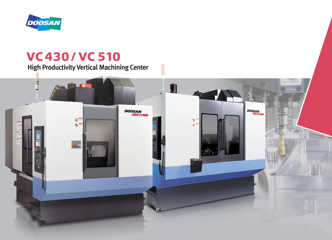
DOOSAN VC430-510
12
High Productivity Vertical Machining Center
description
DOOSAN VC430/510 Brochure
Transcript of DOOSAN VC430-510
High Productivity Vertical Machining Center
02 High Productivity Vertical Machining Center
High Productivity Vertical Machining Center
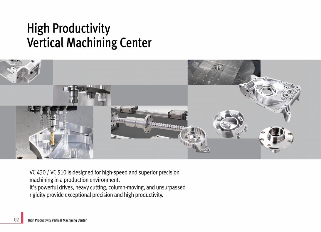
VC 430 / VC 510 is designed for high-speed and superior precision machining in a production environment.It's powerful drives, heavy cutting, column-moving, and unsurpassed rigidity provide exceptional precision and high productivity.
03
High Productivity Vertical Machining Center
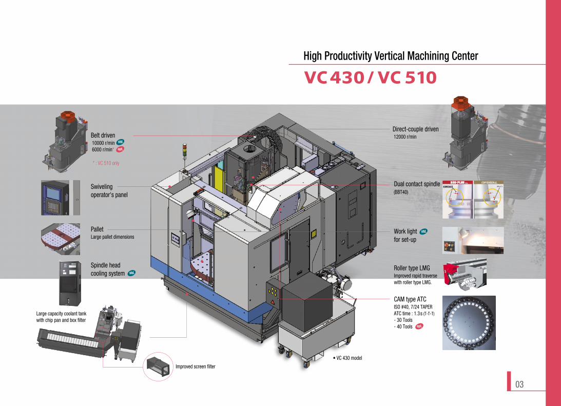
Direct-couple driven12000 r/min
CAM type ATCISO #40, 7/24 TAPERATC time : 1.3s (T-T-T)- 30 Tools- 40 Tools
Dual contact spindle(BBT40)
Work light for set-up
Roller type LMGImproved rapid traverse with roller type LMG.
Large capacity coolant tankwith chip pan and box filter
Improved screen filter
• VC 430 model
* : VC 510 only
Swiveling operator's panel
PalletLarge pallet dimensions
Spindle head cooling system
Belt driven10000 r/min6000 r/min* opt.
std.
opt.
std.
std.
04 High Productivity Vertical Machining Center
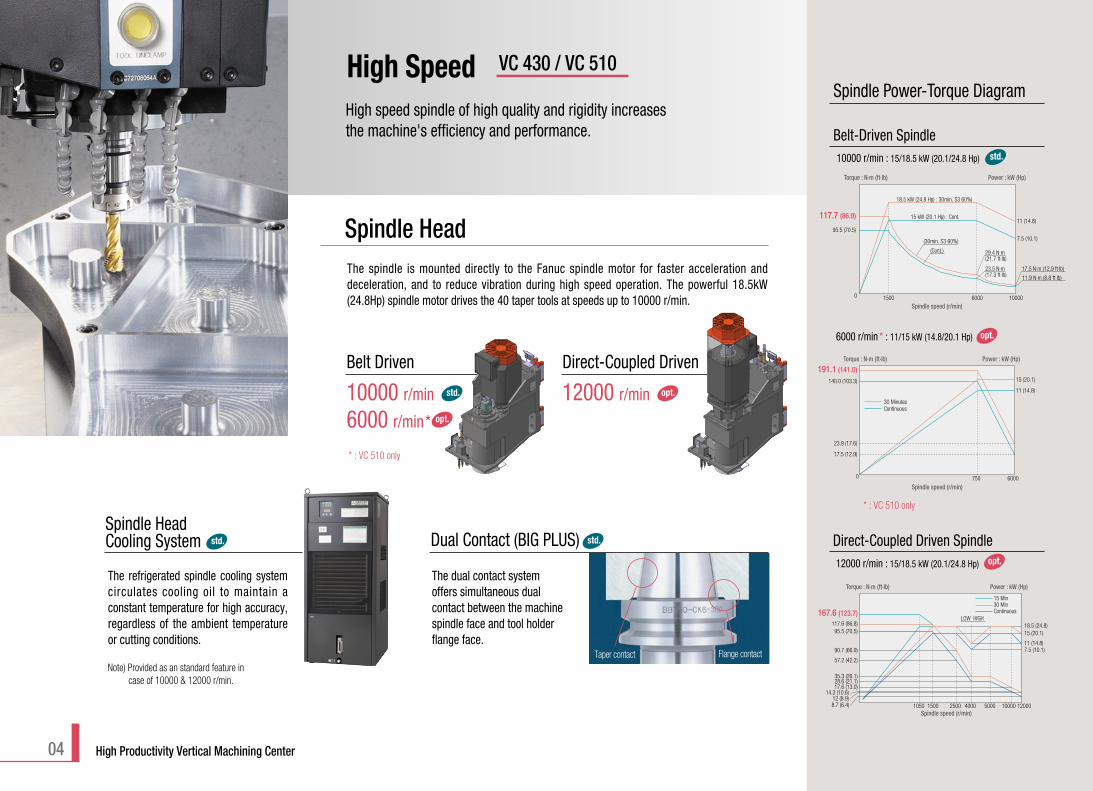
High SpeedHigh speed spindle of high quality and rigidity increases the machine's efficiency and performance.
VC 430 / VC 510
Taper contact Flange contact
Spindle HeadThe spindle is mounted directly to the Fanuc spindle motor for faster acceleration anddeceleration, and to reduce vibration during high speed operation. The powerful 18.5kW(24.8Hp) spindle motor drives the 40 taper tools at speeds up to 10000 r/min.
The refrigerated spindle cooling systemcirculates cooling oil to maintain aconstant temperature for high accuracy,regardless of the ambient temperatureor cutting conditions.
The dual contact systemoffers simultaneous dualcontact between the machinespindle face and tool holderflange face.
Spindle Head Cooling System Dual Contact (BIG PLUS) std.std.
Belt Driven
10000 r/min
6000 r/min*
Direct-Coupled Driven
12000 r/min opt.
opt.
std.
Spindle Power-Torque Diagram
Belt-Driven Spindle
Direct-Coupled Driven Spindle
10000 r/min : 15/18.5 kW (20.1/24.8 Hp)
6000 r/min * : 11/15 kW (14.8/20.1 Hp)
12000 r/min : 15/18.5 kW (20.1/24.8 Hp)
Spindle speed (r/min)
Torque : N.m (ft.lb) Power : kW (Hp)
1500 6000 10000
11 (14.8)117.7 (86.9)
95.5 (70.5)
7.5 (10.1)
29.4 N.m(21.7 ft.lb)
23.5 N.m(17.3 ft.lb)
17.5 N.m (12.9 ft.lb)
11.9 N.m (8.8 ft.lb)
18.5 kW (24.8 Hp) : 30min, S3 60%)
15 kW (20.1 Hp) : Cont.
(30min, S3 60%)
(Cont.)
0
Continuous30 Minutes
Power : kW (Hp)Torque : N.m (ft.lb)
Spindle speed (r/min)60007500
17.5 (12.9)
23.9 (17.6)
140.0 (103.3)
191.1 (141.0)15 (20.1)
11 (14.8)
Torque : N.m (ft.lb) Power : kW (Hp)
Spindle speed (r/min)12000100005000
Continuous30 Min
28.6 (21.1)35.3 (26.1)
95.5 (70.5)117.6 (86.8)
1500 2500 4000105012 (8.9)8.7 (6.4)
167.6 (123.7)
18.5 (24.8)15 (20.1)
11 (14.8)7.5 (10.1)
17.6 (13.0)
15 Min
14.3 (10.6)
LOW HIGH
90.7 (66.9)
57.2 (42.2)
std.
opt.
opt.
* : VC 510 only
* : VC 510 only
Note) Provided as an standard feature in case of 10000 & 12000 r/min.
Suitable for high productivity.
The automatic 180 degree indexing pallet table is an integral part of the VC 430 / VC 510. The table mechanism is mounted directly to the bed of the machine on a horizontal plane toenhance the table rigidity. Because the table is stationary during machining, the non-cutting sideof the indexing table can be set-up while the workpiece is being machined on the machine side.As an added feature, rotary table cables and work holding hoses can be run down from the sheetmetal wall.
Tool change time (C-T-C) 4.3 sTool change time (T-T-T) 1.3 s
Model VC 430 VC 510
Pallet change time 5 s 5.5 s
Pallet loading capacity 2-300 kg 2-350 kg(2-661.4 lb) (2-771.6 lb)
Pallet size 2-712 x 475 mm 2-860 x 570 mm(2-28.0 x 18.7 inch) (2-33.9 x 22.4 inch)
Minimized Non Cutting Time Dual Indexing Pallet (APC)
Sophisticated mechanisms thatsignificantly reduce non-cutting time.Tool-to-tool: 1.3 s, Chip-to-chip: 4.3 s
05
Automatic Tool Changer
30 station
40 station
The 30 station, automatic toolchanger accepts 40 taper tooling.Its reliable double arm systemprovides a 1.3 second tool-to-tooltimes. ATC has a bi-directionalmagazine that automatically takesthe shortest path.
Tool Magazine
opt.
std.
• An additional hydraulic unit may be required according to rotary table specifications.
• Recommended rotary table sizeVC 430 : ø170mm (6.7 inch)VC 510 : ø200mm (7.9 inch)
High RigidityStable bed and column assemblies are designed for high speed and heavy duty machining.
Rigid Body Interface for Additional Equipment
Rapid Traverse
The one piece bed is a rigid, heavily ribbed, Meehanite casting that remains stableunder the heaviest cutting conditions. Fine grained Meehanite cast iron is used forits excellent vibration absorbing characteristics. The VC 430 / VC 510 features asuperior traveling column design. The table, and therefore the workpieces, remainsstationary during machining. This design provides a uniform load to the guideways,ball screws and motors.
Travel Axes (X/Y/Z) Connection Example of AdditionalAxis Interface
Connection Example ofFixture Interface
06 High Productivity Vertical Machining Center
VC 430 / VC 510
VC 430 : 560 / 430 / 570 mm(22.0 / 16.7 / 22.4 inch)
VC 510 : 762 / 516 / 570 mm(30.0 / 20.3 / 22.4 inch)
Model VC 430 VC 510
X-axis m/min (ipm) 40 (1574.8) 40 (1574.8)
Y-axis m/min (ipm) 40 (1574.8) 40 (1574.8)
Z-axis m/min (ipm) 36 (1417.3) 32 (1259.8)
Linear motion guideways and high speed servo motors apply high rapid axis movement. This reduces non-cutting time and machining time for greater productivity.
Fixture check list (for hydraulic / pneumatic fixtures)
Pressure source
Hydraulic P/T A/B
Pneumatic P/T A/B
Number of ports
1pair (2-PT 3/8" port) 3pair (6-PT 3/8" port)
2pair (4-PT 3/8" port) 4pair (8-PT 1/4" port)
Hydraulic power unit
• Supply scope : User Doosan (Please check the below detail specification, if you want Doosan to supply.)
Use Doosan standard unit 24 L/min (6.3 gal/min) / 50 bar
Special requiremen L/min (gal/min) at MPa (psi)
• Contact Doosan for more information
Pneumauic
Hydraulic
07
1. Swivelling operating consoleAn easy-to-use operation panel which can swivel from 0-90°
2. The ATC operating button is accessible from the main panel.
3. Portable MPGPortable MPG makes a workpiecesetting easier for the operator.
This can give mucheasier operationand maintenancefor ATC.
Operating Panel
Magazine : CW
Magazine : CCW
Advanced Performance & Units
The large-scale cutting oil pump and tank arelocated away from the machine's main body toprevent heat transfer. The pump generates 60 HZpower when measured at the pump outlet. Themain axis cutting oil device (T-S-C) is available asan option.
Through Spindle Coolant
Flood Coolant
The large capacity coolant tank is located onrollers. The coolant tank is isolated from themachine bed to prevent heat transfer andassociated thermal distortion. Providing highvolume flood coolant as a standard feature.
Coolant System
std.
opt.
A standard rigid tapping functionallows synchronized, high-speedtapping with a standard colletchuck. This eliminates the need for special tap holders.The tapping depthcan be accuratelycontrolled.
Rigid Tapping
A lubrication system providesautomatic lubrication to allguideways and ball screws.The way oil is delivered bypiston distributors whichprecisely meter the volume. Alow level alarm prevents themachine from restarting.
Lubrication
Coolant tank
Coolant chiller
Coolant Chiller
The coolant chiller lowers coolant temperature,helping to cool both the workpiece and toolduring the machining operation. When usinginsoluble cutting oils, a coolant chiller isrecommended to cool heated oil and preserve machining precision.
opt.
• Model : VC 430 / VC 510• Material : A7075F• Tool : Endmill ø12mm (ø0.5 in.)
(4 blades)
Designed for exceptionally high accuracy and minimal thermal displacement and vibration.
• Machining results may differ from those shown here, reflecting differences in environmental and machining conditions.
Machining AccuracyFor increased repeatability and reliability
6.0 µm
Roundness
• Spindle speed : 10000 r/min• Feedrate : 1500 mm/min (59.1 ipm)
Ra 0.2 µm
Roughness
08 High Productivity Vertical Machining Center
• ø80mm (3.15 in.) Face mill (6Z)Machining rate
432 cm3/min (26.4 in3/min)
Face mill Carbon steel (SM45C)
Spindle speed
1500 r/min
Feedrate
2700 mm/min (106.3 ipm)
Machining CapacityProvides high productivity and high accuracy in a variety of machining operations
15 mm(0.59 in.)
Ø51 mm(2 in.)
64 mm(2.52 in.)
3 mm(0.12 in.)
64 mm(2.52 in.)
2 mm(0.08 in.)
64 mm(2.52 in.)
5 mm(0.2 in.)
64 mm(2.52 in.)
2 mm(0.08 in.)
• ø80mm (3.15 in.) Face mill (6Z)Machining rate
691 cm3/min (42.2 in3/min)
Face mill Gray casting (GC25)
Spindle speed
1500 r/min
Feedrate
3600 mm/min (141.7 ipm)
15 mm(0.59 in.)
Ø51 mm(2 in.)
64 mm(2.52 in.)
3 mm(0.12 in.)
64 mm(2.52 in.)
2 mm(0.08 in.)
64 mm(2.52 in.)
5 mm(0.2 in.)
64 mm(2.52 in.)
3 mm(0.12 in.)
• ø30mm (1.2 in.) Endmill (6Z)Machining rate
36cm3/min (2.2 in3/min)
End mill Carbon steel (SM45C)
Spindle speed
222 r/min
Feedrate
80 mm/min (3.1 ipm)
15 mm(0.59 in.)
Ø51 mm(2 in.)
64 mm(2.52 in.)
3 mm(0.12 in.)
64 mm(2.52 in.)
2 mm(0.08 in.) 15 mm
(0.59 in.)
64 mm(2.52 in.)
5 mm(0.2 in.)
Machining rate
172 cm3/min (10.5 in3/min)
U-drill Carbon steel (SM45C)
Spindle speed
750 r/min
Feedrate
84 mm/min (3.3 ipm)
15 mm(0.59 in.)
Ø51 mm(2 in.)
64 mm(2.52 in.)
3 mm(0.12 in.)
64 mm(2.52 in.)
2 mm(0.08 in.)
Ø51 mm(2 in.)
64 mm(2.52 in.)
5 mm(0.2 in.)
Tool
M30 x P3.5
Tap Carbon steel (SM45C)
Spindle speed
212 r/min
Feedrate
742 mm/min (29.2 ipm)
15 mm(0.59 in.)
Ø51 mm(2 in.)
64 mm(2.52 in.)
3 mm(0.12 in.)
64 mm(2.52 in.)
2 mm(0.08 in.)
64 mm(2.52 in.)
5 mm(0.2 in.)
• ø80mm (3.15 in.) Face mill (6Z)Machining rate
1785 cm3/min (109 in3/min)
Face mill Aluminum (AL6061)
Spindle speed
1500 r/min
Feedrate
5580 mm/min (219.7 ipm)
15 mm(0.59 in.)
Ø51 mm(2 in.)
64 mm(2.52 in.)
3 mm(0.12 in.)
64 mm(2.52 in.)
2 mm(0.08 in.)
64 mm(2.52 in.)
5 mm(0.2 in.) 64 mm
(2.52 in.)
5 mm(0.2 in.)
Unit : mm (inch)External Dimensions
Top View Front View Side View
Top View Front View Side View762 (30.0)
Door open
X Stroke1095 (43.1)
2200 (86.6)
690 (27.2)Door open
560 (22.0)X-stroke
2738
(107
.8) [
Belt
drive
type
]29
88 (1
17.6
) [Di
rect
driv
e ty
pe]
2150
(84.
6)58
8 (2
3.1)
100 (3.9)2391 (94.1) 946 (37.2)
91 (3.6)
710
(28.
0) 1422
(56.
0)
2783
(109
.6) [
40 to
ol]
2575
(101
.4) [
30 to
ol]
2150
(84.
6)42
5(1
6.7)
208
(8.2
)[4
0 to
ol]
1125
(44.
3)
910
(35.
8)
430 (16.9)Y-stroke
150
(5.9
)57
0 (2
2.4)
Z-st
roke
450 (17.7) 1565 (61.6) 875 (34.4)
610 (24.0)Door open28
90 (1
13.8
)
1015 (40.0)
365
(14.
4)72
0(2
8.3)
1085
(42.
7)18
05(4
2.7)
1185 (46.7)
R760(29.9)
R400
(15.7)
68 (2.7
)
337(13.3)
1312
(51.
7)
1046 (41.2)91 (3.6) 2200 (86.6)
530
(20.
9)10
7(4
.2)
460(18.1)
762 (30.0)
Door open
X Stroke1095 (43.1)
Oil cooler
338(13.3)
390 (15.4)
3260
(128
.3)
146
(5.7
)
1100 (43.3)
1312
(51.
7)
2580 (101.6)
1295 (51.0)1285 (50.6)
440
(17.
3)15
0(5
.9)
2002
(78.
8)12
58 (4
9.5)
415
(16.
3)84
3 (3
3.2)
R760(29.9)
R400
(15.7)
2695
(106
.1) [
30 to
ol]
2903
(114
.3) [
40 to
ol]
940
(37.
0)29
39 (1
15.7
)
425
(16.
7)22
70 (8
9.4)
2270
(89.
4)
700
(27.
6)
1100 (43.3)2580 (101.6)91(3.6)
313
0 (1
23.2
) [Di
rect
driv
e ty
pe]
560
(22.
0)
762 (30.0)
Door open
X Stroke1095 (43.1)
2830
(111
.4) [
Belt
drive
type
]
Table
100(3.9)
100(3.9)
100(3.9)
165(6.5)
165(6.5)
100(3.9)
100(3.9)
100(3.9)
100(3.9)
100(3.9)
1180 (46.5)
ø1200 (47.2)
56 (2.2
)10
0(3
.9)
100
(3.9
)10
0(3
.9)
100
(3.9
)10
0(3
.9)
100
(3.9
)56 (2.2
)
365 ±0.05(14.4 ±0.002)
365 ±0.05(14.4 ±0.002)
58-M16 TAP
25(1.0)
100(3.9)
25(1.0)
100(3.9)
712
(28.
0)
2-ø30 F7
58(2.3)
58(2.3)
30 (1.2
)30 (1.2
)
100(3.9)
100(3.9)
100(3.9)
412(16.2)
ø1400 (55.1)
412(16.2)
570(22.4)
2-ø42(1.7)F7
84-M16x2 TAP
570(22.4)
100(3.9)
1340 (52.8)
100(3.9)
100(3.9)
100(3.9)
100(3.9)
100(3.9)
100(3.9)
100
(3.9
)10
0(3
.9)
100
(3.9
)10
0(3
.9)
100
(3.9
)
860
(33.
9)
100
(3.9
)10
0(3
.9)
100
(3.9
)
212(8.3)
212(8.3)
Table
• Pull Stud installation required with15 degrees as the standard (DIN shape)
BT40
Tool Shank
ø17
ø7 H
OLE
L2
65.4
ø23
M16 x P2.015°
ø14
2925
ø17 2
423
ø1930°
22.622.6
16.1
ø44.
45
TAPER GAGE LINE
60°
ø53
16.6
10 7/24 TAPER
M16 x P2.0
ø63
09
10 High Productivity Vertical Machining Center
Machine SpecificationsStandard Feature
Optional Feature
• APC guard for safety
• ATC guard for safety
• Assembly & operation tools
• Coolant tank & chip pan
• Door interlock
• Full enclosure splash guard
• Installation parts
• Signal tower (red, yellow, green)
• Spindle head cooling system
• Rigid tapping
• Work light
• 4th axis preparation
• Automatic front door
• Automatic power off
• Automatic tool measurement
• Automatic workpiece measurement
• Chip conveyor & chip bucket
• Hydraulic line for work fixture system
• Oil skimmer
• Pneumatic line for work fixture system
• Rotary table
• Shower coolant
• Test bar
• Through spindle coolant
• The specifications and information above-mentioned may be changed without prior notice.• For more details, please contact Doosan.
* : For large scale structure installation and tool interference, please consult with the technical department of Doosan** : Avaliable in pallet changer, *** : Avaliable in tool magazine,
Note : { } are optional.
X-axis (longitudinal movement of table) mm (inch) 560 (22.0) 762 (30.0)
Y-axis (cross movement of saddle) mm (inch) 430 (16.9) 516 (20.3)
Z-axis (vertical movement of spindle head) mm (inch) 570 (22.4)
Distance from spindle nose to table top mm (inch) 150~720 (5.9 ~ 28.3) 210 ~ 780 (8.3 ~ 30.7)
Distance from spindle center to column guideway mm (inch) 495 (19.5) 530 (20.9)
Pallet size mm (inch) 2-712 x 475 (2-28.0 x 18.7) 2-860 x 570 (2-33.9 x 22.4)
Pallet loading capacity kg (lb) 2-300 (2-661.4) 2-350 (2-771.6)
Max. workpiece height mm (inch) 460 (18.1)* 520 (20.5)
Pallet surface 2-29-M16 x P2.0 42-M16 x P2.0 Taper
Max. spindle speed r/min 10000 {12000} 10000 {6000,12000}
Spindle taper ISO #40 7/24 Taper
Max. spindle torque N.m (ft.lb) 117.7 {167.6} (86.9 {123.7}) 117.7 {191.1, 167.6} (86.9 {141.0, 123.7})
Rapid traverse rate (X / Y / Z) m/min (ipm) 40 / 40 / 36 (1574.8 / 1574.8 / 1417.3) 40 / 40 / 32 (1574.8 / 1574.8 / 1259.8)
Cutting feedrate mm/min (ipm) 18000 (708.7) 16000 (629.9)
Type of tool shank MAS403 BT40
Tool storage capacity 30 {40}
Max. tool diameter mm (inch) 80 {76} (3.2 {3.0})
Max. tool diameter without adjacent tools mm (inch) 125 (4.9)
Max. tool length mm (inch) 220 (8.7)** / 300 (11.8)***
Max. tool weight kg (lb) 8 (17.6)
Tool change time (tool-to-tool) s 1.3
Tool change time (chip-to-chip) s 4.3
Number of pallet ea 2
Pallet change time s 5 5.5
Spindle motor (30min) kW (Hp) 18.5 (24.8) {10000, 12000 r/min} 15 (20.1) {6000 r/min}
Feed motor (X / Y / Z) kW (Hp) 4.0 / 4.0 / 4.0 (5.4 / 5.4 / 5.4)
Electric power supply (rated capacity) kVA 40.3 {10000, 12000 r/min} 35.1 {6000 r/min}
Compressed air supply MPa 0.54
Coolant tank capacity L (galon) 300 (79.3) 420 (111.0)
Lubrication tank capacity (available) L (galon) 2 (0.53)
Machine height mm (inch) 2740 (107.9) 3130 (123.2)
Machine dimensions (L x W) mm (inch) 2960 x 2370 (116.5 x 93.3) 3260 x 2580 (128.3 x 101.6)
Machine weight kg (lb) 7800 (17196) 9200 (20282.2)
DOOSAN Fanuc i series
Features VC 430 VC 510
Travel
Table
Spindle
Feedrate
Automatictool changer
Automaticpallet changer
Motor
Power source
Tank capacity
Machine size
NC system
11
NC Unit Specifications DOOSAN Fanuc i seriesAXES CONTROL
- Controlled axes 3 (X,Y,Z)
- Simultaneously controllable axes
Positioning (G00) / Linear interpolation (G01) : 3 axes
Circular interpolation (G02, G03) : 2 axes
- Backlash compensation
- Follow up
- Least command increment 0.001mm (0.0001 inch)
- Least input increment 0.001mm (0.0001 inch)
- Machine lock all axes / Z axis
- Mirror image Reverse axis movement
(setting screen and M - function)
- Stored pitch error compensation
Pitch error offset compensation for each axis
- Stored stroke check 1 Overtraval controlled by software
- Absolute pulse coder
- Position switch
INTERPOLATION & FEED FUNCTION
- 2nd reference point return G30
- Circular interpolation G02, G03
- Cylinderical interpolation G07.1
- Dwell G04
- Exact stop check G09, G61 (mode)
- Feed per minute
- Feedrate override (10% increments) 0 - 200 %
- Helical interpolation
- Jog override (10% increments) 0 - 200 %
- Linear interpolation G01
- Manual handle feed 1 unit
- Manual handle feedrate 0.1 / 0.01 / 0.001 mm
- Override cancel M48 / M49
- Positioning G00
- Rapid traverse override F0 (fine feed), 25 / 50 / 100 %
- Reference point return G27, G28, G29
- Skip function G31
SPINDLE & M-CODE FUNCTION
- M- code function M 3 digits
- Spindle orientation
- Spindle serial output
- Spindle speed command S5 digits
- Spindle speed override (10% increments) 10 - 150 %
TOOL FUNCTION
- Tool nose radius compensation G40, G41, G42
- Number of tool offsets 400 ea
- Tool length compensation G43, G44, G49
- Tool life management
- Tool number command T2 digits
- Tool offset memory C
Geometry / Wear and Length / Radius offset memory
- Tool position offset G45 - G48
PROGRAMMING & EDITING FUNCTION
- Absolute / Incremental programming G90 / G91
- Automatic Coordinate system setting
- Background editing
- Canned cycle G73, G74, G76, G80 - G89, G99
- Circular interpolation by radius programming
- Custom macro B
- Addition of custom macro common variables
#100 - #199, #500 - #999
- Decimal point input
- Extended part program editing
- Reader / puncher interface RS - 232C
- Inch / metric conversion G20 / G21
- Label skip
- Local / Machine coordinate system G52 / G53
- Maximum commandable value
±99,999.999 mm (±9,999.9999 inch)
- No. of Registered programs 400 ea
- Optional block skip
- Optional stop M01
- Part program storage 1280m [512 kB]
- Palyback
- Program number O4-digits
- Program protect
- Program stop / end M00 / M02,M30
- Rigid tapping G84, G74
- Sub program Up to 4 nesting
- Tape code ISO / EIA Automatic discrimination
- Thread cutting
- Work coordinate system G54 - G59
OTHERS FUNCTIONS (Operation, setting & Display, etc)
- 3rd / 4th reference return
- Additional work coordinate system G54.1 P1 - 48 (48 pairs)
- AICC1 (AI Contour Control 1) with Hardware : 40 block preview
- Alarm display
- Alarm history display
- Automatic corner override G62
- Clock function
- Coordinate rotation G68,G69
- Cycle start / Feed hold
- Display of PMC alarm message
Message display when PMC alarm occurred
- Machine condition selection function
- Embeded ethernet
- Dry run
- Graphic display Tool path drawing
- Help function
- High speed skip function (only NC function)
- Loadmeter display
- Look ahead control G08
- MDI / DISPLAY unit
8.4" Color TFT LCD, keyboard for data input (small), soft-keys
- Memory card interface
- Operation functions Tape / Memory / MDI / Manual
- Operation history display
- Optional angle chamfering / corner R
- Polar coordinate command G15 / G16
- Programmable data input
Tool offset and work offset are entered by G10, G11
- Programmable mirror image G50.1 / G51.1
- Run hour and part number display
- Scaling G50, G51
- Search function Sequence NO. / Program NO.
- Self - diagnostic function
- Servo setting screen
- Single block
- Single direction positioning G60
- Stored stroke check 2
OPTIONAL SPECIFICATIONS
- Additional controlled axes 4 axes in total
- AICC II (AI Contour Control II) with Hardware : 200 block preview
- Fast Data server
- Fast Ethernet
High Productivity Vertical Machining Center
http://www.doosaninfracore.com/machinetools
Design and specifications are subject to change without prior notice.EX 1204SPi-ser
Head Office :
Doosan Tower 20th FL., 18-12, Euljiro-6Ga, Jung-Gu, Seoul, Korea 100-730 Tel : ++82-2-3398-8693 / 8671 / 8680 Fax : ++82-2-3398-8699
Doosan Infracore America Corp.:
19A Chapin Rd. Pine Brook, NJ 07058, U.S.A. Tel : ++1-973-618-2500 Fax : ++1-973-618-2501
Doosan Infracore Germany GmbH :
Emdener Strasse 24, D-41540 Dormagen, Germany. Tel : ++49-2173-8509-0 Fax : ++49-2173-8509-60
Doosan Infracore Yantai Co., LTD :
13 Building, 140 Tianlin Road, Xuhui District, Shanghai, China (200233) Tel : ++86-21-6440-3384 (808, 805) Fax : ++86-21-6440-3389