Effect of Plasma Nitriding on Fatigue Behavior of Ti-6Al ...
12
Article 1 Effect of Plasma Nitriding on Fatigue Behavior of 2 Ti-6Al-4V Alloy 3 Michele C. B. de Castro 1 , Antônio A. Couto 1,2 , Gisele F. C. Almeida 1,2, *, Marcos Massi 2 , Nelson B. 4 de Lima 1 , Argemiro da Silva Sobrinho 3 , Mariano Castagnet 1 , Gleicy L. Xavier 1 and Rene R. 5 Oliveira 1 6 1 Instituto de Pesquisas Energéticas e Nucleares, São Paulo, Brazil 7 2 Universidade Presbiteriana Mackenzie – São Paulo, Brazil 8 3 Instituto Tecnológico de Aeronáutica—ITA/DCTA, São José dos Campos, Brazil. 9 * Correspondence: [email protected]; Tel.: +55-11-99639-8967 10 11 Abstract: The Ti-6Al-4V alloy is widely used in the manufacture of components that should have 12 low density, high corrosion resistance, and fatigue strength. The fatigue strength can be improved 13 by surface modification. The aim of this study was to determine the influence of plasma nitriding 14 on the fatigue behavior of Ti-6Al-4V alloy with a lamellar microstructure (Widmanstätten type). 15 Nitriding was executed at 720 °C for 4 hours in an atmosphere with N2, Ar and H2. Samples 16 microstructure characterization was carried out by X-ray diffraction analysis, optical microscopy 17 and scanning electron microscopy. The average roughness of the specimens was determined, and 18 fatigue tests were executed in a bending-rotating machine with reverse tension cycles (R= -1). X-ray 19 diffraction analysis revealed the matrix phases α and β, and the phases Ɛ-Ti2N and δ-TiN in the 20 nitrided alloy. A nitrogen diffusion layer was formed between the substrate and the titanium 21 nitrides. Plasma nitriding resulted in an increase in low cycle fatigue strength, whereas at high 22 cycles, both conditions exhibit similar behavior. The fracture surface of the fatigue tested specimens 23 clearly revealed the lamellar microstructure. The fracture mechanism appears to be due to cracking 24 at the interface of α and β phases of the lamellar microstructure. 25 Keywords: Ti-6Al-4V alloy; plasma nitriding; fatigue 26 27 1. Introduction 28 Titanium and its alloys are widely used in many areas such as the aerospace, food, naval and 29 nuclear industries as well as the material to produce surgical implants. Among the various titanium 30 alloys, Ti-6Al-4V is the most widely used as it has properties such as ease of manufacture, excellent 31 corrosion resistance, biocompatibility, and low density. There are certain disadvantages related to 32 the use of this alloy what include low surface hardness, low fatigue strength, low wear properties 33 and high friction coefficient [1–5]. Fatigue failure of the Ti-6Al-4V alloy occurs when cyclic stresses 34 are applied to it and the stress levels at which this failure occurs are below the yield stress of the 35 alloy, which is usually determined from tensile tests [6]. This type of failure hinders the use of this 36 alloy in applications requiring high fatigue strength [7]. 37 Many surface modification techniques can be used to improve the fatigue properties of this 38 alloy. Among these, the more widely used techniques are heat treatments, coating the surface with 39 films and thermo-chemical treatments [8]. Nitriding is a thermo-chemical treatment and it can be 40 done using gas, laser or plasma and the last is more efficient because it favors formation of a 41 titanium solid solution with interstitial elements such as nitrogen [8]. Conventional gas nitriding 42 was the preferred technique for a long time. This technique has some disadvantages such as poor 43 surface finish, long duration of the process and insufficient control over formation of phases. 44 Presently, plasma nitriding is used because it is cheaper, can be done on parts with varied 45 geometries, provides excellent control over formation of phases and does not require long process 46 Preprints (www.preprints.org) | NOT PEER-REVIEWED | Posted: 28 December 2018 doi:10.20944/preprints201812.0326.v1 © 2018 by the author(s). Distributed under a Creative Commons CC BY license. Peer-reviewed version available at Materials 2019, 12, 520; doi:10.3390/ma12030520
Transcript of Effect of Plasma Nitriding on Fatigue Behavior of Ti-6Al ...
Article 1
Effect of Plasma Nitriding on Fatigue Behavior of 2
Ti-6Al-4V Alloy 3
Michele C. B. de Castro1, Antônio A. Couto1,2, Gisele F. C. Almeida1,2,*, Marcos Massi2, Nelson B. 4 de Lima1, Argemiro da Silva Sobrinho3, Mariano Castagnet1, Gleicy L. Xavier1 and Rene R. 5 Oliveira1 6
1 Instituto de Pesquisas Energéticas e Nucleares, São Paulo, Brazil 7 2 Universidade Presbiteriana Mackenzie – São Paulo, Brazil 8 3 Instituto Tecnológico de Aeronáutica—ITA/DCTA, São José dos Campos, Brazil. 9 * Correspondence: [email protected]; Tel.: +55-11-99639-8967 10 11
Abstract: The Ti-6Al-4V alloy is widely used in the manufacture of components that should have 12 low density, high corrosion resistance, and fatigue strength. The fatigue strength can be improved 13 by surface modification. The aim of this study was to determine the influence of plasma nitriding 14 on the fatigue behavior of Ti-6Al-4V alloy with a lamellar microstructure (Widmanstätten type). 15 Nitriding was executed at 720 °C for 4 hours in an atmosphere with N2, Ar and H2. Samples 16 microstructure characterization was carried out by X-ray diffraction analysis, optical microscopy 17 and scanning electron microscopy. The average roughness of the specimens was determined, and 18 fatigue tests were executed in a bending-rotating machine with reverse tension cycles (R= -1). X-ray 19 diffraction analysis revealed the matrix phases α and β, and the phases Ɛ-Ti2N and δ-TiN in the 20 nitrided alloy. A nitrogen diffusion layer was formed between the substrate and the titanium 21 nitrides. Plasma nitriding resulted in an increase in low cycle fatigue strength, whereas at high 22 cycles, both conditions exhibit similar behavior. The fracture surface of the fatigue tested specimens 23 clearly revealed the lamellar microstructure. The fracture mechanism appears to be due to cracking 24 at the interface of α and β phases of the lamellar microstructure. 25
Keywords: Ti-6Al-4V alloy; plasma nitriding; fatigue 26 27
1. Introduction 28 Titanium and its alloys are widely used in many areas such as the aerospace, food, naval and 29
nuclear industries as well as the material to produce surgical implants. Among the various titanium 30 alloys, Ti-6Al-4V is the most widely used as it has properties such as ease of manufacture, excellent 31 corrosion resistance, biocompatibility, and low density. There are certain disadvantages related to 32 the use of this alloy what include low surface hardness, low fatigue strength, low wear properties 33 and high friction coefficient [1–5]. Fatigue failure of the Ti-6Al-4V alloy occurs when cyclic stresses 34 are applied to it and the stress levels at which this failure occurs are below the yield stress of the 35 alloy, which is usually determined from tensile tests [6]. This type of failure hinders the use of this 36 alloy in applications requiring high fatigue strength [7]. 37
Many surface modification techniques can be used to improve the fatigue properties of this 38 alloy. Among these, the more widely used techniques are heat treatments, coating the surface with 39 films and thermo-chemical treatments [8]. Nitriding is a thermo-chemical treatment and it can be 40 done using gas, laser or plasma and the last is more efficient because it favors formation of a 41 titanium solid solution with interstitial elements such as nitrogen [8]. Conventional gas nitriding 42 was the preferred technique for a long time. This technique has some disadvantages such as poor 43 surface finish, long duration of the process and insufficient control over formation of phases. 44 Presently, plasma nitriding is used because it is cheaper, can be done on parts with varied 45 geometries, provides excellent control over formation of phases and does not require long process 46
Preprints (www.preprints.org) | NOT PEER-REVIEWED | Posted: 28 December 2018
© 2018 by the author(s). Distributed under a Creative Commons CC BY license.
Preprints (www.preprints.org) | NOT PEER-REVIEWED | Posted: 28 December 2018 doi:10.20944/preprints201812.0326.v1
© 2018 by the author(s). Distributed under a Creative Commons CC BY license.
Peer-reviewed version available at Materials 2019, 12, 520; doi:10.3390/ma12030520
2 of 12
times to render satisfactory results. One disadvantage of plasma nitriding is the formation of 47 cathode arcs that could damage the surface of the alloy during treatment [8,9]. 48
Nitriding is done by diffusing nitrogen from the surface into the α phase in the alloy matrix. 49 The diffusion process results in a gradual decrease in nitrogen content and hardness from the 50 surface into the alloy. The outermost layer formed during nitriding consists of TiN with a 51 face-centered cubic (FCC) structure. Just below this layer, the Ti2N phase with a tetragonal structure 52 forms. Below these two layers forms a layer of alpha phase titanium (Ti-α) rich in diffused nitrogen 53 [3,5,8]. Formation of the TiN and Ti2N phases on the Ti-6Al-4V alloy surface increases surface 54 hardness and creates compressive stresses in the surface, that delays the crack nucleation stage and 55 thereby increases the fatigue life of the alloy [10,11]. 56
Plasma nitriding can be affected by many factors and the main ones are the duration of 57 nitriding, temperature and gas composition in the nitriding atmosphere. A number of studies have 58 been carried out to compare the thickness of nitride layers as a function of process time and 59 temperature, and further, the effect of nitride layer thickness on improvements in fatigue properties. 60 According to Rahman et al [12], in their studies on plasma nitriding, the improvement in fatigue 61 properties was marked when the treatment was done at 500 °C for 6 hours in a nitriding atmosphere 62 containing nitrogen and hydrogen in the proportion 3:1. Rodriguez et al [10] carried out nitriding at 63 850 °C and 900 °C for 1 to 4 hours and reported that the nitride layer had a positive effect on the 64 fatigue properties, and this was caused by the compressive residual stress in the alloy, delaying thus 65 the crack nucleation step. According to Farokhzadeh et al [1], plasma nitriding carried out at 600 °C 66 and 900 °C for 24 hours revealed a 23 % improvement in fatigue strength of the Ti-6Al-4V alloy 67 nitrided at 600 °C, compared to a non-nitrided alloy. 68
In view of these observations, the objective of this study was to evaluate the fatigue behavior of 69 Ti-6Al-4V alloy before and after plasma nitriding. The starting Ti-6Al-4V alloy had a Widmanstätten 70 type microstructure. After the plasma nitriding, the nitride layers were studied and fatigue tests 71 were carried out in a bending-rotating machine. 72
2. Materials and Methods 73 In this study, a Ti-6Al-4V alloy with composition conforming to ASTM F136-13 [13] standard 74
was used. The alloy was acquired in the form of annealed rods 12.7 mm in diameter and 3140 mm 75 long. Specimens for the fatigue and the tensile tests were machined from the Ti-6Al-4V rods as per 76 ASTM E8-11 [14] standard. The specimens used for the fatigue and the tensile tests were heat treated 77 to obtain a Widmanstätten type microstructure. The heat treatment was carried out at 1050 °C for 30 78 minutes in an argon atmosphere. The heating rate was 20 °C/min and the specimens were 79 subsequently cooled at 6 °C/min. 80
The heat-treated specimens were ultrasonically cleaned in a mixture of water with a surfactant, 81 and then cleaned in isopropyl alcohol for more than 15 minutes before plasma nitriding. Plasma 82 nitriding was carried out in a mixed gas flux containing N2, Ar and H2 in the proportion 5:5:1. Table 83 1 shows the average process parameters that were used along with their standard deviations. 84
Table 1. Average and standard deviations of parameters used in plasma nitriding. 85
Temperature (°C) Pressure (Pa) Current (A) Voltage (V) Power (W)
730 ± 3 586.62 2.65 ± 0.04 416 ± 1 1102 ± 24 86 Microstructure characterization of as non-nitrided and nitrided Ti-6Al-4V alloy samples was 87
carried out using optical microscopy, scanning electron microscopy and X-ray diffraction analysis. 88 Initially, 5 mm thick cross-sectional samples were cut from the rods. These samples were mounted 89 and ground sequentially with SiC papers of 280, 400, 600 and 1200 mesh. Subsequently, the samples 90 were polished with colloidal silicon containing 0.04 µm particles. The etchant used to reveal the 91 microstructure was a solution of 10 mL hydrofluoric acid (HF) and 2.5 mL nitric acid (HNO3) for 3 92 seconds. The etched samples were examined in an Olympus BX60 optical microscope. The 93 non-nitrided and nitrided samples were also studied by X-ray diffraction analysis using Cu kα 94
Preprints (www.preprints.org) | NOT PEER-REVIEWED | Posted: 28 December 2018 Preprints (www.preprints.org) | NOT PEER-REVIEWED | Posted: 28 December 2018 doi:10.20944/preprints201812.0326.v1
Peer-reviewed version available at Materials 2019, 12, 520; doi:10.3390/ma12030520
3 of 12
(λ=0.1542 nm). The specimens were scanned at angles between 20° to 80° and scan rate of 2° min-1. 95 Evaluation of the X-ray diffractograms was done with the software Crystallographica Search-Match. 96
Surface roughness of the non-nitrided and nitrided samples was determined. This was done 97 with a Mitutoyo roughness measuring device. In these measurements, a sample cutoff length of 0.08 98 mm was used, as per ISO 4287:1997 [15] standard. Five random measurements were carried out on 99 every sample and then the averages as well as the standard deviations of the measured values were 100 determined. The roughness parameter used was Arithmetic Roughness (Ra). The tensile tests were 101 carried out as per ASTM E8-11 [14] standard in a universal mechanical testing machine Instron 102 4400R with the crosshead speed of 1 mm/min. 103
The fatigue tests were carried out in a bending-rotating machine with reverse tension cycles. 104 Therefore, in the fatigue tests on untreated and nitrided specimens, a loading ratio of R=-1 and 105 rotation velocity of 3000 rpm were used. At least 3 specimens in each condition (non-nitrided and 106 nitrided) were tested at each applied stress cycle. The fatigue tests were started at stress cycles equal 107 to 60% of the yield stress. In subsequent tests, the stresses were lowered till it reached a point at 108 which the specimen did not fail even after about 107 cycles. The stress versus number of cycles (S-N) 109 curves were plotted from the medium values of the fatigue test results. The facture surfaces of the 110 specimens that failed in the fatigue tests were examined in a Philips XL-30 scanning electron 111 microscope. 112
3. Results and Discussions 113
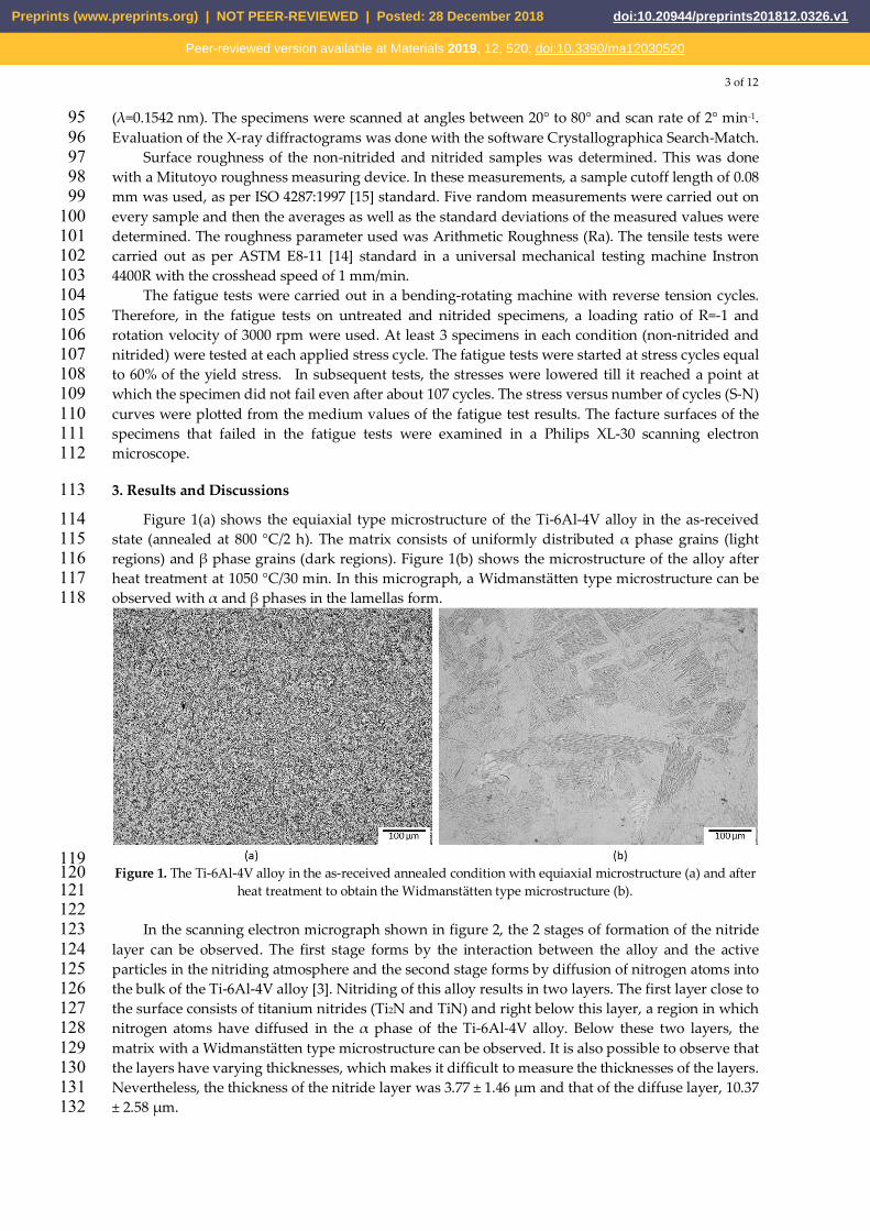
Figure 1(a) shows the equiaxial type microstructure of the Ti-6Al-4V alloy in the as-received 114 state (annealed at 800 °C/2 h). The matrix consists of uniformly distributed α phase grains (light 115 regions) and β phase grains (dark regions). Figure 1(b) shows the microstructure of the alloy after 116 heat treatment at 1050 °C/30 min. In this micrograph, a Widmanstätten type microstructure can be 117 observed with α and β phases in the lamellas form. 118
119 Figure 1. The Ti-6Al-4V alloy in the as-received annealed condition with equiaxial microstructure (a) and after 120
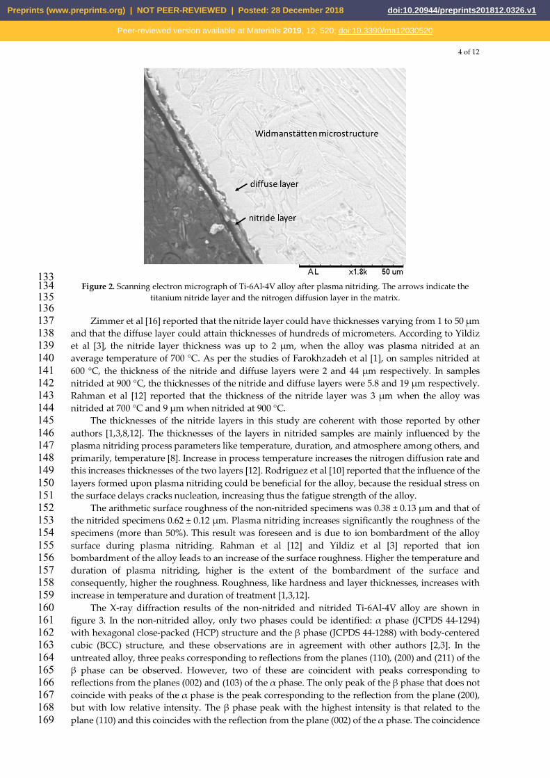
heat treatment to obtain the Widmanstätten type microstructure (b). 121 122 In the scanning electron micrograph shown in figure 2, the 2 stages of formation of the nitride 123
layer can be observed. The first stage forms by the interaction between the alloy and the active 124 particles in the nitriding atmosphere and the second stage forms by diffusion of nitrogen atoms into 125 the bulk of the Ti-6Al-4V alloy [3]. Nitriding of this alloy results in two layers. The first layer close to 126 the surface consists of titanium nitrides (Ti2N and TiN) and right below this layer, a region in which 127 nitrogen atoms have diffused in the α phase of the Ti-6Al-4V alloy. Below these two layers, the 128 matrix with a Widmanstätten type microstructure can be observed. It is also possible to observe that 129 the layers have varying thicknesses, which makes it difficult to measure the thicknesses of the layers. 130 Nevertheless, the thickness of the nitride layer was 3.77 ± 1.46 µm and that of the diffuse layer, 10.37 131 ± 2.58 µm. 132
Preprints (www.preprints.org) | NOT PEER-REVIEWED | Posted: 28 December 2018 Preprints (www.preprints.org) | NOT PEER-REVIEWED | Posted: 28 December 2018 doi:10.20944/preprints201812.0326.v1
Peer-reviewed version available at Materials 2019, 12, 520; doi:10.3390/ma12030520
4 of 12
133 Figure 2. Scanning electron micrograph of Ti-6Al-4V alloy after plasma nitriding. The arrows indicate the 134
titanium nitride layer and the nitrogen diffusion layer in the matrix. 135 136
Zimmer et al [16] reported that the nitride layer could have thicknesses varying from 1 to 50 µm 137 and that the diffuse layer could attain thicknesses of hundreds of micrometers. According to Yildiz 138 et al [3], the nitride layer thickness was up to 2 µm, when the alloy was plasma nitrided at an 139 average temperature of 700 °C. As per the studies of Farokhzadeh et al [1], on samples nitrided at 140 600 °C, the thickness of the nitride and diffuse layers were 2 and 44 µm respectively. In samples 141 nitrided at 900 °C, the thicknesses of the nitride and diffuse layers were 5.8 and 19 µm respectively. 142 Rahman et al [12] reported that the thickness of the nitride layer was 3 µm when the alloy was 143 nitrided at 700 °C and 9 µm when nitrided at 900 °C. 144
The thicknesses of the nitride layers in this study are coherent with those reported by other 145 authors [1,3,8,12]. The thicknesses of the layers in nitrided samples are mainly influenced by the 146 plasma nitriding process parameters like temperature, duration, and atmosphere among others, and 147 primarily, temperature [8]. Increase in process temperature increases the nitrogen diffusion rate and 148 this increases thicknesses of the two layers [12]. Rodriguez et al [10] reported that the influence of the 149 layers formed upon plasma nitriding could be beneficial for the alloy, because the residual stress on 150 the surface delays cracks nucleation, increasing thus the fatigue strength of the alloy. 151
The arithmetic surface roughness of the non-nitrided specimens was 0.38 ± 0.13 µm and that of 152 the nitrided specimens 0.62 ± 0.12 µm. Plasma nitriding increases significantly the roughness of the 153 specimens (more than 50%). This result was foreseen and is due to ion bombardment of the alloy 154 surface during plasma nitriding. Rahman et al [12] and Yildiz et al [3] reported that ion 155 bombardment of the alloy leads to an increase of the surface roughness. Higher the temperature and 156 duration of plasma nitriding, higher is the extent of the bombardment of the surface and 157 consequently, higher the roughness. Roughness, like hardness and layer thicknesses, increases with 158 increase in temperature and duration of treatment [1,3,12]. 159
The X-ray diffraction results of the non-nitrided and nitrided Ti-6Al-4V alloy are shown in 160 figure 3. In the non-nitrided alloy, only two phases could be identified: α phase (JCPDS 44-1294) 161 with hexagonal close-packed (HCP) structure and the β phase (JCPDS 44-1288) with body-centered 162 cubic (BCC) structure, and these observations are in agreement with other authors [2,3]. In the 163 untreated alloy, three peaks corresponding to reflections from the planes (110), (200) and (211) of the 164 β phase can be observed. However, two of these are coincident with peaks corresponding to 165 reflections from the planes (002) and (103) of the α phase. The only peak of the β phase that does not 166 coincide with peaks of the α phase is the peak corresponding to the reflection from the plane (200), 167 but with low relative intensity. The β phase peak with the highest intensity is that related to the 168 plane (110) and this coincides with the reflection from the plane (002) of the α phase. The coincidence 169
Preprints (www.preprints.org) | NOT PEER-REVIEWED | Posted: 28 December 2018 Preprints (www.preprints.org) | NOT PEER-REVIEWED | Posted: 28 December 2018 doi:10.20944/preprints201812.0326.v1
Peer-reviewed version available at Materials 2019, 12, 520; doi:10.3390/ma12030520
5 of 12
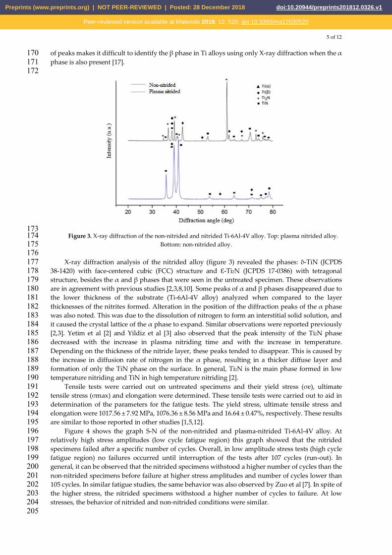
of peaks makes it difficult to identify the β phase in Ti alloys using only X-ray diffraction when the α 170 phase is also present [17]. 171
172
173 Figure 3. X-ray diffraction of the non-nitrided and nitrided Ti-6Al-4V alloy. Top: plasma nitrided alloy. 174
Bottom: non-nitrided alloy. 175 176 X-ray diffraction analysis of the nitrided alloy (figure 3) revealed the phases: δ-TiN (JCPDS 177
38-1420) with face-centered cubic (FCC) structure and Ɛ-Ti2N (JCPDS 17-0386) with tetragonal 178 structure, besides the α and β phases that were seen in the untreated specimen. These observations 179 are in agreement with previous studies [2,3,8,10]. Some peaks of α and β phases disappeared due to 180 the lower thickness of the substrate (Ti-6Al-4V alloy) analyzed when compared to the layer 181 thicknesses of the nitrites formed. Alteration in the position of the diffraction peaks of the α phase 182 was also noted. This was due to the dissolution of nitrogen to form an interstitial solid solution, and 183 it caused the crystal lattice of the α phase to expand. Similar observations were reported previously 184 [2,3]. Yetim et al [2] and Yildiz et al [3] also observed that the peak intensity of the Ti2N phase 185 decreased with the increase in plasma nitriding time and with the increase in temperature. 186 Depending on the thickness of the nitride layer, these peaks tended to disappear. This is caused by 187 the increase in diffusion rate of nitrogen in the α phase, resulting in a thicker diffuse layer and 188 formation of only the TiN phase on the surface. In general, Ti2N is the main phase formed in low 189 temperature nitriding and TiN in high temperature nitriding [2]. 190
Tensile tests were carried out on untreated specimens and their yield stress (σe), ultimate 191 tensile stress (σmax) and elongation were determined. These tensile tests were carried out to aid in 192 determination of the parameters for the fatigue tests. The yield stress, ultimate tensile stress and 193 elongation were 1017.56 ± 7.92 MPa, 1076.36 ± 8.56 MPa and 16.64 ± 0.47%, respectively. These results 194 are similar to those reported in other studies [1,5,12]. 195
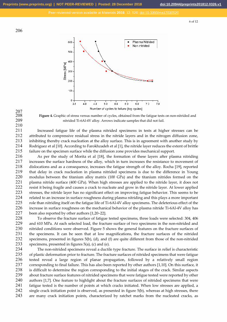
Figure 4 shows the graph S-N of the non-nitrided and plasma-nitrided Ti-6Al-4V alloy. At 196 relatively high stress amplitudes (low cycle fatigue region) this graph showed that the nitrided 197 specimens failed after a specific number of cycles. Overall, in low amplitude stress tests (high cycle 198 fatigue region) no failures occurred until interruption of the tests after 107 cycles (run-out). In 199 general, it can be observed that the nitrided specimens withstood a higher number of cycles than the 200 non-nitrided specimens before failure at higher stress amplitudes and number of cycles lower than 201 105 cycles. In similar fatigue studies, the same behavior was also observed by Zuo et al [7]. In spite of 202 the higher stress, the nitrided specimens withstood a higher number of cycles to failure. At low 203 stresses, the behavior of nitrided and non-nitrided conditions were similar. 204
205
Preprints (www.preprints.org) | NOT PEER-REVIEWED | Posted: 28 December 2018 Preprints (www.preprints.org) | NOT PEER-REVIEWED | Posted: 28 December 2018 doi:10.20944/preprints201812.0326.v1
Peer-reviewed version available at Materials 2019, 12, 520; doi:10.3390/ma12030520
6 of 12
206
207 Figure 4. Graphic of stress versus number of cycles, obtained from the fatigue tests on non-nitrided and 208
nitrided Ti-6Al-4V alloy. Arrows indicate samples that did not fail. 209 210
Increased fatigue life of the plasma nitrided specimens in tests at higher stresses can be 211 attributed to compressive residual stress in the nitride layers and in the nitrogen diffusion zone, 212 inhibiting thereby crack nucleation at the alloy surface. This is in agreement with another study by 213 Rodriguez et al [10]. According to Farokhzadeh et al [1], the nitride layer reduces the extent of brittle 214 failure on the specimen surface while the diffusion zone provides mechanical support. 215
As per the study of Morita et al [18], the formation of these layers after plasma nitriding 216 increases the surface hardness of the alloy, which in turn increases the resistance to movement of 217 dislocations and as a consequence, increases the fatigue strength of the alloy. Rocha [19], reported 218 that delay in crack nucleation in plasma nitrided specimens is due to the difference in Young 219 modulus between the titanium alloy matrix (100 GPa) and the titanium nitrides formed on the 220 plasma nitride surface (400 GPa). When high stresses are applied to the nitride layer, it does not 221 resist it being fragile and causes a crack to nucleate and grow in the nitride layer. At lower applied 222 stresses, the nitride layer has no significant effect on improving fatigue behavior. This seems to be 223 related to an increase in surface roughness during plasma nitriding and this plays a more important 224 role than nitriding itself on the fatigue life of Ti-6Al-4V alloy specimens. The deleterious effect of the 225 increase in surface roughness on the mechanical behavior of the plasma nitride Ti-6Al-4V alloy has 226 been also reported by other authors [1,20–22]. 227
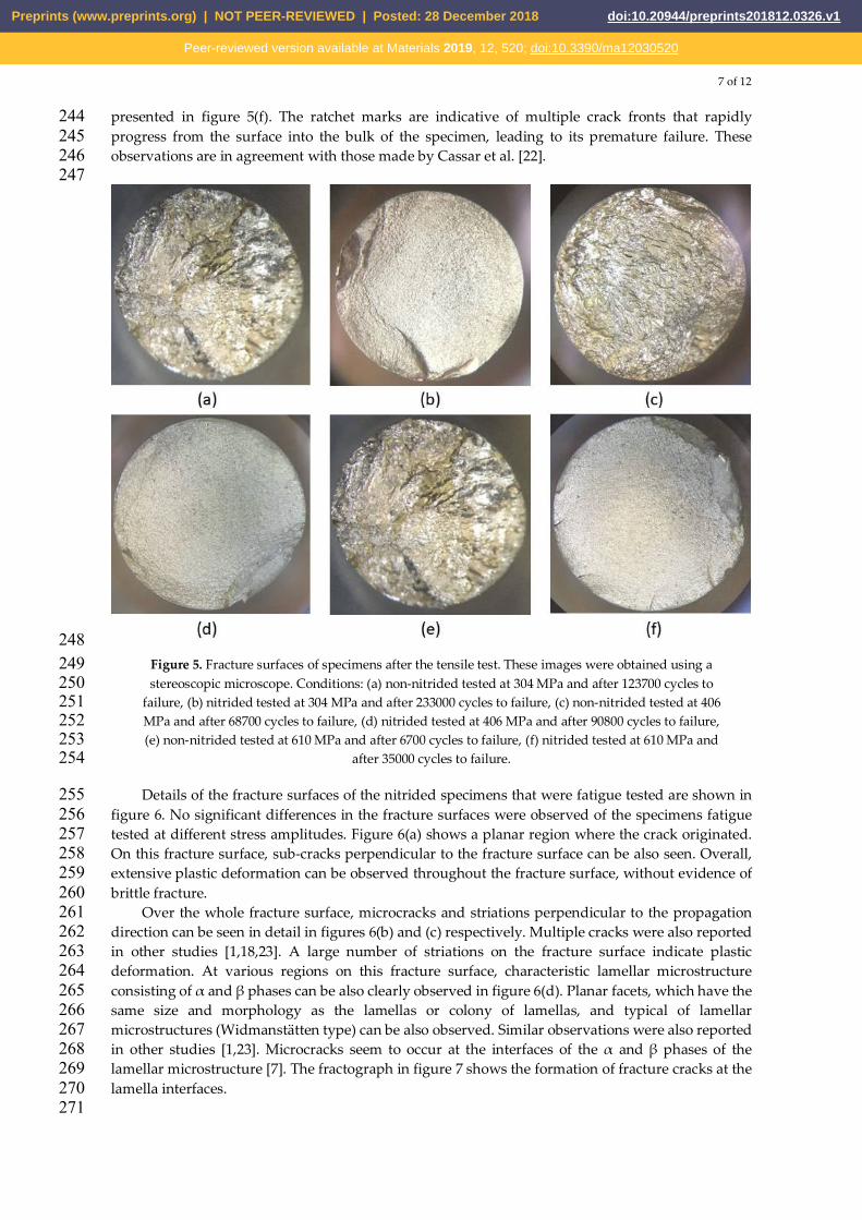
To observe the fracture surface of fatigue tested specimens, three loads were selected: 304, 406 228 and 610 MPa. At each selected load, the fracture surface of two specimens in the non-nitrided and 229 nitrided conditions were observed. Figure 5 shows the general features on the fracture surfaces of 230 the specimens. It can be seen that at low magnifications, the fracture surfaces of the nitrided 231 specimens, presented in figures 5(b), (d), and (f) are quite different from those of the non-nitrided 232 specimens, presented in figures 5(a), (c) and (e). 233
The non-nitrided specimens reveal a ductile type fracture. The surface in relief is characteristic 234 of plastic deformation prior to fracture. The fracture surfaces of nitrided specimens that were fatigue 235 tested reveal a large region of planar propagation, followed by a relatively small region 236 corresponding to final failure. This has also been reported by other authors [1,10]. On this surface, it 237 is difficult to determine the region corresponding to the initial stages of the crack. Similar aspects 238 about fracture surface features of nitrided specimens that were fatigue tested were reported by other 239 authors [1,7]. One feature to highlight about the fracture surfaces of nitrided specimens that were 240 fatigue tested is the number of points at which cracks initiated. When low stresses are applied, a 241 single crack initiation point is observed, as presented in figure 5(b), whereas at high stresses, there 242 are many crack initiation points, characterized by ratchet marks from the nucleated cracks, as 243
Preprints (www.preprints.org) | NOT PEER-REVIEWED | Posted: 28 December 2018 Preprints (www.preprints.org) | NOT PEER-REVIEWED | Posted: 28 December 2018 doi:10.20944/preprints201812.0326.v1
Peer-reviewed version available at Materials 2019, 12, 520; doi:10.3390/ma12030520
7 of 12
presented in figure 5(f). The ratchet marks are indicative of multiple crack fronts that rapidly 244 progress from the surface into the bulk of the specimen, leading to its premature failure. These 245 observations are in agreement with those made by Cassar et al. [22]. 246
247
248 Figure 5. Fracture surfaces of specimens after the tensile test. These images were obtained using a 249 stereoscopic microscope. Conditions: (a) non-nitrided tested at 304 MPa and after 123700 cycles to 250
failure, (b) nitrided tested at 304 MPa and after 233000 cycles to failure, (c) non-nitrided tested at 406 251 MPa and after 68700 cycles to failure, (d) nitrided tested at 406 MPa and after 90800 cycles to failure, 252 (e) non-nitrided tested at 610 MPa and after 6700 cycles to failure, (f) nitrided tested at 610 MPa and 253
after 35000 cycles to failure. 254
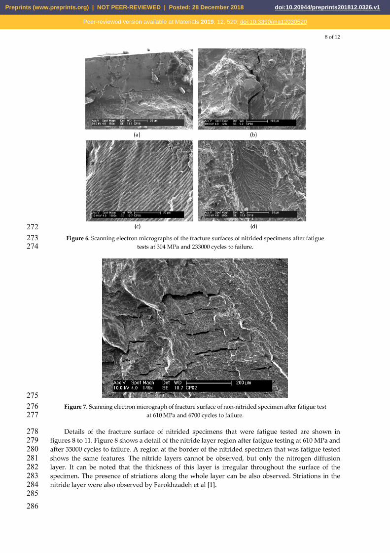
Details of the fracture surfaces of the nitrided specimens that were fatigue tested are shown in 255 figure 6. No significant differences in the fracture surfaces were observed of the specimens fatigue 256 tested at different stress amplitudes. Figure 6(a) shows a planar region where the crack originated. 257 On this fracture surface, sub-cracks perpendicular to the fracture surface can be also seen. Overall, 258 extensive plastic deformation can be observed throughout the fracture surface, without evidence of 259 brittle fracture. 260
Over the whole fracture surface, microcracks and striations perpendicular to the propagation 261 direction can be seen in detail in figures 6(b) and (c) respectively. Multiple cracks were also reported 262 in other studies [1,18,23]. A large number of striations on the fracture surface indicate plastic 263 deformation. At various regions on this fracture surface, characteristic lamellar microstructure 264 consisting of α and β phases can be also clearly observed in figure 6(d). Planar facets, which have the 265 same size and morphology as the lamellas or colony of lamellas, and typical of lamellar 266 microstructures (Widmanstätten type) can be also observed. Similar observations were also reported 267 in other studies [1,23]. Microcracks seem to occur at the interfaces of the α and β phases of the 268 lamellar microstructure [7]. The fractograph in figure 7 shows the formation of fracture cracks at the 269 lamella interfaces. 270
271
Preprints (www.preprints.org) | NOT PEER-REVIEWED | Posted: 28 December 2018 Preprints (www.preprints.org) | NOT PEER-REVIEWED | Posted: 28 December 2018 doi:10.20944/preprints201812.0326.v1
Peer-reviewed version available at Materials 2019, 12, 520; doi:10.3390/ma12030520
8 of 12
272 Figure 6. Scanning electron micrographs of the fracture surfaces of nitrided specimens after fatigue 273
tests at 304 MPa and 233000 cycles to failure. 274
275 Figure 7. Scanning electron micrograph of fracture surface of non-nitrided specimen after fatigue test 276
at 610 MPa and 6700 cycles to failure. 277
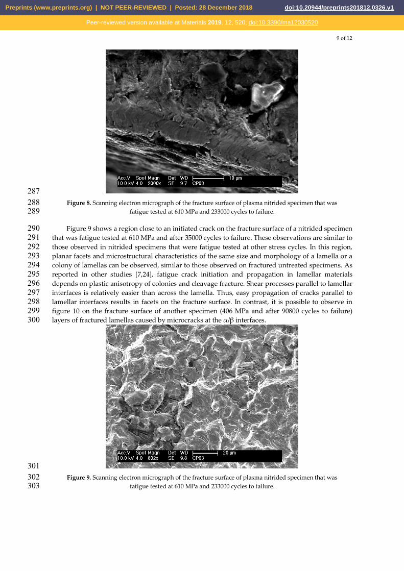
Details of the fracture surface of nitrided specimens that were fatigue tested are shown in 278 figures 8 to 11. Figure 8 shows a detail of the nitride layer region after fatigue testing at 610 MPa and 279 after 35000 cycles to failure. A region at the border of the nitrided specimen that was fatigue tested 280 shows the same features. The nitride layers cannot be observed, but only the nitrogen diffusion 281 layer. It can be noted that the thickness of this layer is irregular throughout the surface of the 282 specimen. The presence of striations along the whole layer can be also observed. Striations in the 283 nitride layer were also observed by Farokhzadeh et al [1]. 284
285 286
Preprints (www.preprints.org) | NOT PEER-REVIEWED | Posted: 28 December 2018 Preprints (www.preprints.org) | NOT PEER-REVIEWED | Posted: 28 December 2018 doi:10.20944/preprints201812.0326.v1
Peer-reviewed version available at Materials 2019, 12, 520; doi:10.3390/ma12030520
9 of 12
287 Figure 8. Scanning electron micrograph of the fracture surface of plasma nitrided specimen that was 288
fatigue tested at 610 MPa and 233000 cycles to failure. 289
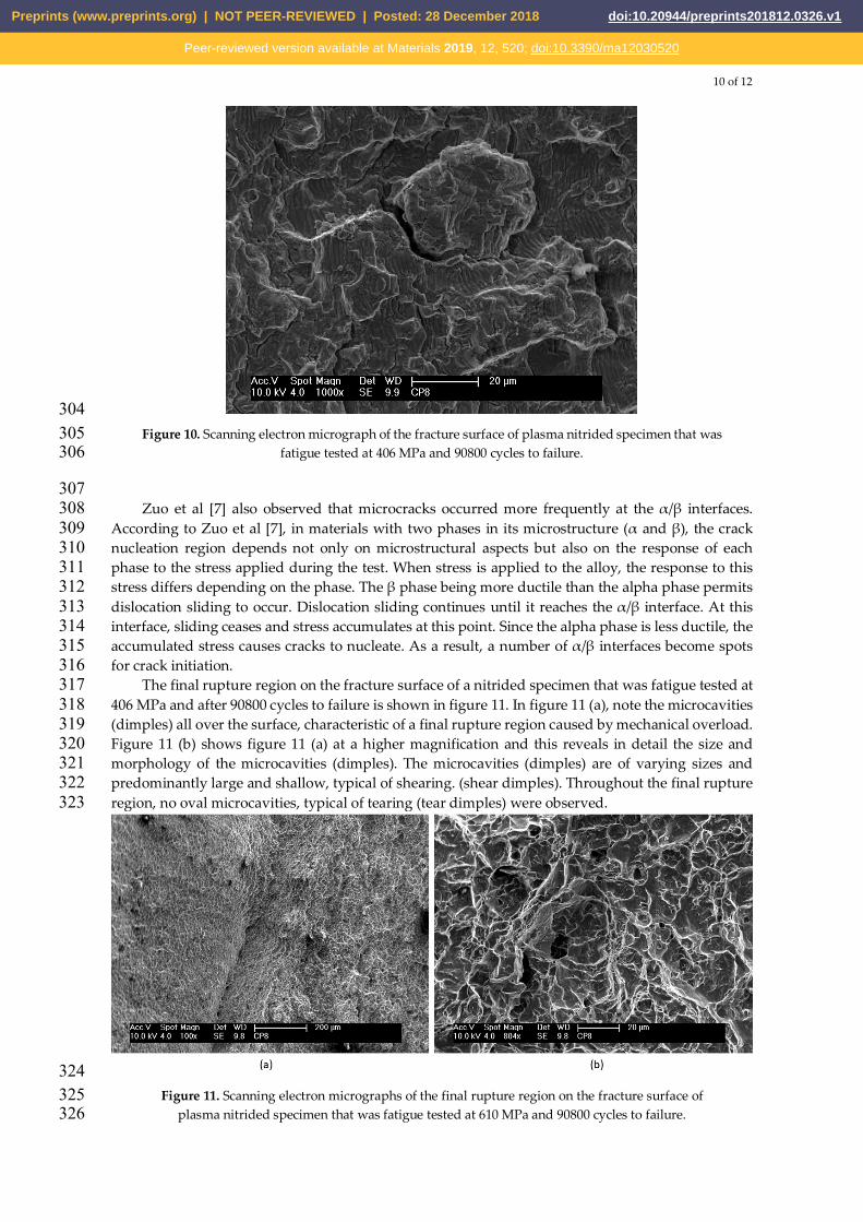
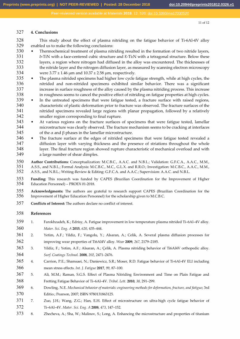
Figure 9 shows a region close to an initiated crack on the fracture surface of a nitrided specimen 290 that was fatigue tested at 610 MPa and after 35000 cycles to failure. These observations are similar to 291 those observed in nitrided specimens that were fatigue tested at other stress cycles. In this region, 292 planar facets and microstructural characteristics of the same size and morphology of a lamella or a 293 colony of lamellas can be observed, similar to those observed on fractured untreated specimens. As 294 reported in other studies [7,24], fatigue crack initiation and propagation in lamellar materials 295 depends on plastic anisotropy of colonies and cleavage fracture. Shear processes parallel to lamellar 296 interfaces is relatively easier than across the lamella. Thus, easy propagation of cracks parallel to 297 lamellar interfaces results in facets on the fracture surface. In contrast, it is possible to observe in 298 figure 10 on the fracture surface of another specimen (406 MPa and after 90800 cycles to failure) 299 layers of fractured lamellas caused by microcracks at the α/β interfaces. 300
301 Figure 9. Scanning electron micrograph of the fracture surface of plasma nitrided specimen that was 302
fatigue tested at 610 MPa and 233000 cycles to failure. 303
Preprints (www.preprints.org) | NOT PEER-REVIEWED | Posted: 28 December 2018 Preprints (www.preprints.org) | NOT PEER-REVIEWED | Posted: 28 December 2018 doi:10.20944/preprints201812.0326.v1
Peer-reviewed version available at Materials 2019, 12, 520; doi:10.3390/ma12030520
10 of 12
304 Figure 10. Scanning electron micrograph of the fracture surface of plasma nitrided specimen that was 305
fatigue tested at 406 MPa and 90800 cycles to failure. 306
307 Zuo et al [7] also observed that microcracks occurred more frequently at the α/β interfaces. 308
According to Zuo et al [7], in materials with two phases in its microstructure (α and β), the crack 309 nucleation region depends not only on microstructural aspects but also on the response of each 310 phase to the stress applied during the test. When stress is applied to the alloy, the response to this 311 stress differs depending on the phase. The β phase being more ductile than the alpha phase permits 312 dislocation sliding to occur. Dislocation sliding continues until it reaches the α/β interface. At this 313 interface, sliding ceases and stress accumulates at this point. Since the alpha phase is less ductile, the 314 accumulated stress causes cracks to nucleate. As a result, a number of α/β interfaces become spots 315 for crack initiation. 316
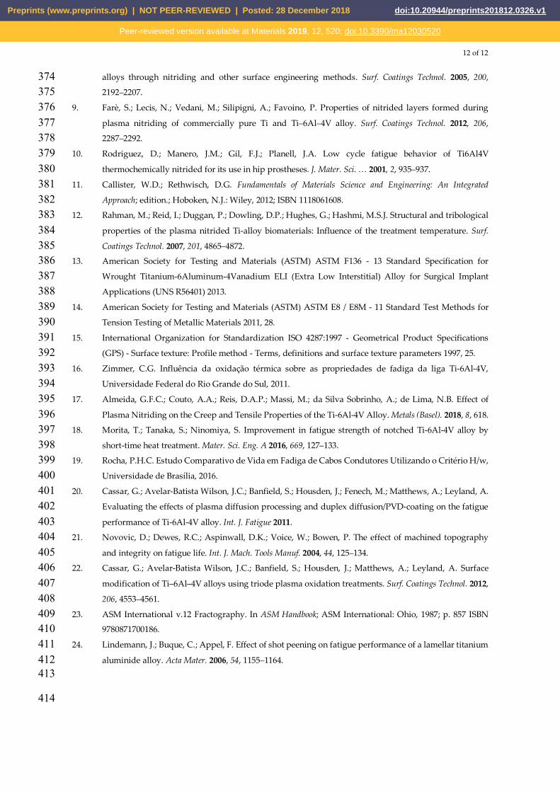
The final rupture region on the fracture surface of a nitrided specimen that was fatigue tested at 317 406 MPa and after 90800 cycles to failure is shown in figure 11. In figure 11 (a), note the microcavities 318 (dimples) all over the surface, characteristic of a final rupture region caused by mechanical overload. 319 Figure 11 (b) shows figure 11 (a) at a higher magnification and this reveals in detail the size and 320 morphology of the microcavities (dimples). The microcavities (dimples) are of varying sizes and 321 predominantly large and shallow, typical of shearing. (shear dimples). Throughout the final rupture 322 region, no oval microcavities, typical of tearing (tear dimples) were observed. 323
324 Figure 11. Scanning electron micrographs of the final rupture region on the fracture surface of 325
plasma nitrided specimen that was fatigue tested at 610 MPa and 90800 cycles to failure. 326
Preprints (www.preprints.org) | NOT PEER-REVIEWED | Posted: 28 December 2018 Preprints (www.preprints.org) | NOT PEER-REVIEWED | Posted: 28 December 2018 doi:10.20944/preprints201812.0326.v1
Peer-reviewed version available at Materials 2019, 12, 520; doi:10.3390/ma12030520
11 of 12
4. Conclusions 327
This study about the effect of plasma nitriding on the fatigue behavior of Ti-6Al-4V alloy 328 enabled us to make the following conclusions: 329 • Thermochemical treatment of plasma nitriding resulted in the formation of two nitride layers, 330
δ-TiN with a face-centered cubic structure and Ɛ-Ti2N with a tetragonal structure. Below these 331 layers, a region where nitrogen had diffused in the alloy was encountered. The thicknesses of 332 the nitride layer and the nitrogen diffusion layer, as measured by scanning electron microscopy 333 were 3.77 ± 1.46 µm and 10.37 ± 2.58 µm, respectively. 334
• The plasma nitrided specimens had higher low cycle fatigue strength, while at high cycles, the 335 nitrided and non-nitrided specimens exhibited similar behavior. There was a significant 336 increase in surface roughness of the alloy caused by the plasma nitriding process. This increase 337 in roughness seems to cancel the positive effect of nitriding on fatigue properties at high cycles. 338
• In the untreated specimens that were fatigue tested, a fracture surface with raised regions, 339 characteristic of plastic deformation prior to fracture was observed. The fracture surfaces of the 340 nitrided specimens revealed large regions with planar propagation, followed by a relatively 341 smaller region corresponding to final rupture. 342
• At various regions on the fracture surfaces of specimens that were fatigue tested, lamellar 343 microstructure was clearly observed. The fracture mechanism seems to be cracking at interfaces 344 of the α and β phases in the lamellar microstructure. 345
• The fracture surface at the edges of nitrided specimens that were fatigue tested revealed a 346 diffusion layer with varying thickness and the presence of striations throughout the whole 347 layer. The final fracture region showed rupture characteristic of mechanical overload and with 348 a large number of shear dimples. 349
Author Contributions: Conceptualization: M.C.B.C., A.A.C. and N.B.L.; Validation: G.F.C.A., A.A.C., M.M., 350 A.S.S., and N.B.L.; Formal Analysis: M.C.B.C., M.C., G.L.X. and R.R.O.; Investigation: M.C.B.C., A.A.C., M.M., 351 A.S.S., and N.B.L.; Writing-Review & Editing: G.F.C.A. and A.A.C.; Supervision: A.A.C. and N.B.L. 352 Funding: This research was funded by CAPES (Brazilian Coordination for the Improvement of Higher 353 Education Personnel) – PROEX 01-2018. 354 Acknowledgments: The authors are grateful to research support CAPES (Brazilian Coordination for the 355 Improvement of Higher Education Personnel) for the scholarship given to M.C.B.C. 356 Conflicts of Interest: The authors declare no conflict of interest. 357
References 358
1. Farokhzadeh, K.; Edrisy, A. Fatigue improvement in low temperature plasma nitrided Ti–6Al–4V alloy. 359 Mater. Sci. Eng. A 2015, 620, 435–444. 360
2. Yetim, A.F.; Yildiz, F.; Vangolu, Y.; Alsaran, A.; Celik, A. Several plasma diffusion processes for 361 improving wear properties of Ti6Al4V alloy. Wear 2009, 267, 2179–2185. 362
3. Yildiz, F.; Yetim, A.F.; Alsaran, A.; Çelik, A. Plasma nitriding behavior of Ti6Al4V orthopedic alloy. 363 Surf. Coatings Technol. 2008, 202, 2471–2476. 364
4. Carrion, P.E.; Shamsaei, N.; Daniewicz, S.R.; Moser, R.D. Fatigue behavior of Ti-6Al-4V ELI including 365 mean stress effects. Int. J. Fatigue 2017, 99, 87–100. 366
5. Ali, M.M.; Raman, S.G.S. Effect of Plasma Nitriding Environment and Time on Plain Fatigue and 367 Fretting Fatigue Behavior of Ti–6Al–4V. Tribol. Lett. 2010, 38, 291–299. 368
6. Dowling, N.E. Mechanical behavior of materials: engineering methods for deformation, fracture, and fatigue; 3rd 369 Editio.; Pearson, 2007; ISBN 9780131863125. 370
7. Zuo, J.H.; Wang, Z.G.; Han, E.H. Effect of microstructure on ultra-high cycle fatigue behavior of 371 Ti–6Al–4V. Mater. Sci. Eng. A 2008, 473, 147–152. 372
8. Zhecheva, A.; Sha, W.; Malinov, S.; Long, A. Enhancing the microstructure and properties of titanium 373
Preprints (www.preprints.org) | NOT PEER-REVIEWED | Posted: 28 December 2018 Preprints (www.preprints.org) | NOT PEER-REVIEWED | Posted: 28 December 2018 doi:10.20944/preprints201812.0326.v1
Peer-reviewed version available at Materials 2019, 12, 520; doi:10.3390/ma12030520
12 of 12
alloys through nitriding and other surface engineering methods. Surf. Coatings Technol. 2005, 200, 374 2192–2207. 375
9. Farè, S.; Lecis, N.; Vedani, M.; Silipigni, A.; Favoino, P. Properties of nitrided layers formed during 376 plasma nitriding of commercially pure Ti and Ti–6Al–4V alloy. Surf. Coatings Technol. 2012, 206, 377 2287–2292. 378
10. Rodriguez, D.; Manero, J.M.; Gil, F.J.; Planell, J.A. Low cycle fatigue behavior of Ti6Al4V 379 thermochemically nitrided for its use in hip prostheses. J. Mater. Sci. … 2001, 2, 935–937. 380
11. Callister, W.D.; Rethwisch, D.G. Fundamentals of Materials Science and Engineering: An Integrated 381 Approach; edition.; Hoboken, N.J.: Wiley, 2012; ISBN 1118061608. 382
12. Rahman, M.; Reid, I.; Duggan, P.; Dowling, D.P.; Hughes, G.; Hashmi, M.S.J. Structural and tribological 383 properties of the plasma nitrided Ti-alloy biomaterials: Influence of the treatment temperature. Surf. 384 Coatings Technol. 2007, 201, 4865–4872. 385
13. American Society for Testing and Materials (ASTM) ASTM F136 - 13 Standard Specification for 386 Wrought Titanium-6Aluminum-4Vanadium ELI (Extra Low Interstitial) Alloy for Surgical Implant 387 Applications (UNS R56401) 2013. 388
14. American Society for Testing and Materials (ASTM) ASTM E8 / E8M - 11 Standard Test Methods for 389 Tension Testing of Metallic Materials 2011, 28. 390
15. International Organization for Standardization ISO 4287:1997 - Geometrical Product Specifications 391 (GPS) - Surface texture: Profile method - Terms, definitions and surface texture parameters 1997, 25. 392
16. Zimmer, C.G. Influência da oxidação térmica sobre as propriedades de fadiga da liga Ti-6Al-4V, 393 Universidade Federal do Rio Grande do Sul, 2011. 394
17. Almeida, G.F.C.; Couto, A.A.; Reis, D.A.P.; Massi, M.; da Silva Sobrinho, A.; de Lima, N.B. Effect of 395 Plasma Nitriding on the Creep and Tensile Properties of the Ti-6Al-4V Alloy. Metals (Basel). 2018, 8, 618. 396
18. Morita, T.; Tanaka, S.; Ninomiya, S. Improvement in fatigue strength of notched Ti-6Al-4V alloy by 397 short-time heat treatment. Mater. Sci. Eng. A 2016, 669, 127–133. 398
19. Rocha, P.H.C. Estudo Comparativo de Vida em Fadiga de Cabos Condutores Utilizando o Critério H/w, 399 Universidade de Brasília, 2016. 400
20. Cassar, G.; Avelar-Batista Wilson, J.C.; Banfield, S.; Housden, J.; Fenech, M.; Matthews, A.; Leyland, A. 401 Evaluating the effects of plasma diffusion processing and duplex diffusion/PVD-coating on the fatigue 402 performance of Ti-6Al-4V alloy. Int. J. Fatigue 2011. 403
21. Novovic, D.; Dewes, R.C.; Aspinwall, D.K.; Voice, W.; Bowen, P. The effect of machined topography 404 and integrity on fatigue life. Int. J. Mach. Tools Manuf. 2004, 44, 125–134. 405
22. Cassar, G.; Avelar-Batista Wilson, J.C.; Banfield, S.; Housden, J.; Matthews, A.; Leyland, A. Surface 406 modification of Ti–6Al–4V alloys using triode plasma oxidation treatments. Surf. Coatings Technol. 2012, 407 206, 4553–4561. 408
23. ASM International v.12 Fractography. In ASM Handbook; ASM International: Ohio, 1987; p. 857 ISBN 409 9780871700186. 410
24. Lindemann, J.; Buque, C.; Appel, F. Effect of shot peening on fatigue performance of a lamellar titanium 411 aluminide alloy. Acta Mater. 2006, 54, 1155–1164. 412
413 414
Preprints (www.preprints.org) | NOT PEER-REVIEWED | Posted: 28 December 2018 Preprints (www.preprints.org) | NOT PEER-REVIEWED | Posted: 28 December 2018 doi:10.20944/preprints201812.0326.v1
Peer-reviewed version available at Materials 2019, 12, 520; doi:10.3390/ma12030520