FICHA TÉCNICA DE PRODUTO PRODUCT DATASHEET · - 2600T series Technical solutions ... verification,...
51
HMI – Automação e Instrumentação, Lda. Rua dos 5 Caminhos, nº 570 4780-382 Santo Tirso PORTUGAL Web: www.hmi.pt Tel. +351 252 850 501 Fax. +351 300 013 487 Email: [email protected] FICHA TÉCNICA DE PRODUTO PRODUCT DATASHEET
Transcript of FICHA TÉCNICA DE PRODUTO PRODUCT DATASHEET · - 2600T series Technical solutions ... verification,...
HMI – Automação e Instrumentação, Lda.
Rua dos 5 Caminhos, nº 570 4780-382 Santo Tirso PORTUGAL Web: www.hmi.pt
Tel. +351 252 850 501 Fax. +351 300 013 487
Email: [email protected]
FICHA TÉCNICA DE PRODUTO
PRODUCT DATASHEET

Data Sheet DS/266CSX/JSX-EN Rev. B
Model 266CSH/CST Multivariable Model 266JSH/JST Multivariable
Pressure transmitters - 2600T series Technical solutions for any application Measurement made easy
Base accuracy — 0.075 % of calibrated span (266CSH, 266JSH) — 0.04 % of calibrated span (266CST, 266JST) 266CSH/CST mass flow measurement with compensation, level measurement with compensation for gases, steam, and liquids — Dynamic compensation of pressure and temperature
changes 266JSH/JST high-performance transmitter for measuring differential pressure, absolute pressure, and process temperature in a single device Proven sensor technology together with state-of-the-art digital technology — Large turn down ratio of up to 100:1
Comprehensive range of functions — Integrated counting function — Binary output as pulse / frequency output or limit monitor 10-year stability — 0.15 % of URL Flexible configuration options — Local configuration via buttons on LCD indicator New TTG (Through-The-Glass) keypad technology — Enables quick and easy local configuration without the
need to open the cover - even in potentially explosive environments
Full compliance with Pressure Equipment Directive (PED) category III
Change from one to two columns
Model 266CSH/CST Multivariable Model 266JSH/JST Multivariable
2 DS/266CSX/JSX-EN Rev. B | 2600T Series Pressure Transmitters 266CSX, 266JSX
Introduction
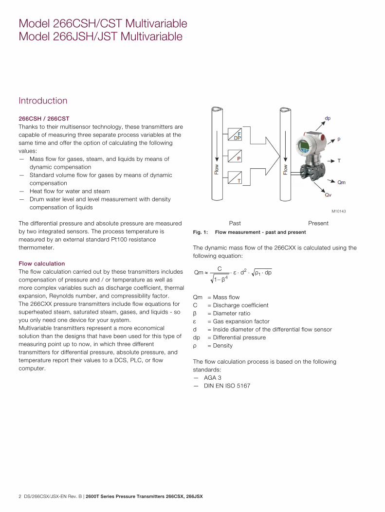
266CSH / 266CST Thanks to their multisensor technology, these transmitters are capable of measuring three separate process variables at the same time and offer the option of calculating the following values: — Mass flow for gases, steam, and liquids by means of
dynamic compensation — Standard volume flow for gases by means of dynamic
compensation — Heat flow for water and steam — Drum water level and level measurement with density
compensation of liquids The differential pressure and absolute pressure are measured by two integrated sensors. The process temperature is measured by an external standard Pt100 resistance thermometer. Flow calculation The flow calculation carried out by these transmitters includes compensation of pressure and / or temperature as well as more complex variables such as discharge coefficient, thermal expansion, Reynolds number, and compressibility factor. The 266CXX pressure transmitters include flow equations for superheated steam, saturated steam, gases, and liquids - so you only need one device for your system. Multivariable transmitters represent a more economical solution than the designs that have been used for this type of measuring point up to now, in which three different transmitters for differential pressure, absolute pressure, and temperature report their values to a DCS, PLC, or flow computer.
Past Present Fig. 1: Flow measurement - past and present
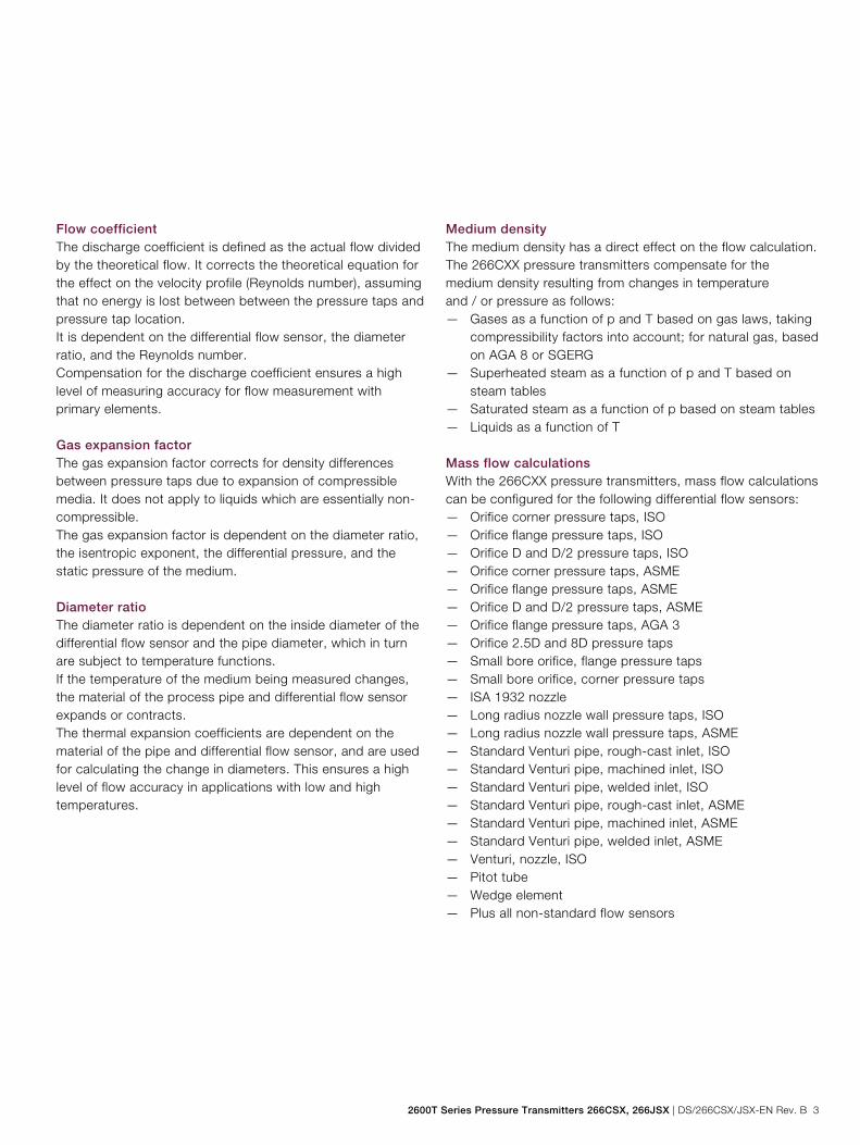
The dynamic mass flow of the 266CXX is calculated using the following equation:
dpρdεβ1
CQm 1
2
4
Qm = Mass flow C = Discharge coefficient β = Diameter ratio ε = Gas expansion factor d = Inside diameter of the differential flow sensor dp = Differential pressure ρ = Density The flow calculation process is based on the following standards: — AGA 3 — DIN EN ISO 5167
2600T Series Pressure Transmitters 266CSX, 266JSX | DS/266CSX/JSX-EN Rev. B 3
Flow coefficient The discharge coefficient is defined as the actual flow divided by the theoretical flow. It corrects the theoretical equation for the effect on the velocity profile (Reynolds number), assuming that no energy is lost between between the pressure taps and pressure tap location. It is dependent on the differential flow sensor, the diameter ratio, and the Reynolds number. Compensation for the discharge coefficient ensures a high level of measuring accuracy for flow measurement with primary elements. Gas expansion factor The gas expansion factor corrects for density differences between pressure taps due to expansion of compressible media. It does not apply to liquids which are essentially non-compressible. The gas expansion factor is dependent on the diameter ratio, the isentropic exponent, the differential pressure, and the static pressure of the medium. Diameter ratio The diameter ratio is dependent on the inside diameter of the differential flow sensor and the pipe diameter, which in turn are subject to temperature functions. If the temperature of the medium being measured changes, the material of the process pipe and differential flow sensor expands or contracts. The thermal expansion coefficients are dependent on the material of the pipe and differential flow sensor, and are used for calculating the change in diameters. This ensures a high level of flow accuracy in applications with low and high temperatures.
Medium density The medium density has a direct effect on the flow calculation. The 266CXX pressure transmitters compensate for the medium density resulting from changes in temperature and / or pressure as follows: — Gases as a function of p and T based on gas laws, taking
compressibility factors into account; for natural gas, based on AGA 8 or SGERG
— Superheated steam as a function of p and T based on steam tables
— Saturated steam as a function of p based on steam tables — Liquids as a function of T Mass flow calculations With the 266CXX pressure transmitters, mass flow calculations can be configured for the following differential flow sensors: — Orifice corner pressure taps, ISO — Orifice flange pressure taps, ISO — Orifice D and D/2 pressure taps, ISO — Orifice corner pressure taps, ASME — Orifice flange pressure taps, ASME — Orifice D and D/2 pressure taps, ASME — Orifice flange pressure taps, AGA 3 — Orifice 2.5D and 8D pressure taps — Small bore orifice, flange pressure taps — Small bore orifice, corner pressure taps — ISA 1932 nozzle — Long radius nozzle wall pressure taps, ISO — Long radius nozzle wall pressure taps, ASME — Standard Venturi pipe, rough-cast inlet, ISO — Standard Venturi pipe, machined inlet, ISO — Standard Venturi pipe, welded inlet, ISO — Standard Venturi pipe, rough-cast inlet, ASME — Standard Venturi pipe, machined inlet, ASME — Standard Venturi pipe, welded inlet, ASME — Venturi, nozzle, ISO — Pitot tube — Wedge element — Plus all non-standard flow sensors

Model 266CSH/CST Multivariable Model 266JSH/JST Multivariable
4 DS/266CSX/JSX-EN Rev. B | 2600T Series Pressure Transmitters 266CSX, 266JSX
ABB offers a complete range of differential flow sensors. We provide the full testing and documentation that your application needs. Whether the requirement is a single orifice plate with a simple Certificate of Conformity or a project requiring full material inspection, traceability, third-party verification, calibration and comprehensive data dossiers – ABB can satisfy all of the requirements. In addition compact solutions are available, OriMaster, a compact orifice flowmeter, and PitoMaster, a compact pitot flowmeter. Level measurement The following functions are available for level measurement with pressure and temperature compensation: — Level measurement with temperature compensation, on
open tank — Level measurement with pressure and temperature
compensation, on closed tank, with and without diaphragm seal
— Fill volume measurement by means of tank shape specification
— Drum water level measurement All of the functionality, including all the data required for compensated mass flow or for level measurement, is configured entirely using the PC-based DTM 266-MV. A simplified setting method, which uses the (optional) LCD indicator, is available for flow and level calculation. EDD-based systems such as handheld terminals are also supported. 266JSH / 266JST This intelligent transmitter provides the user with precise measurements of differential pressure, absolute pressure, and process temperature (the latter by means of an externally connected Pt100 resistance thermometer), in just one device.
Change from two to one column
2600T Series Pressure Transmitters 266CSX, 266JSX | DS/266CSX/JSX-EN Rev. B 5
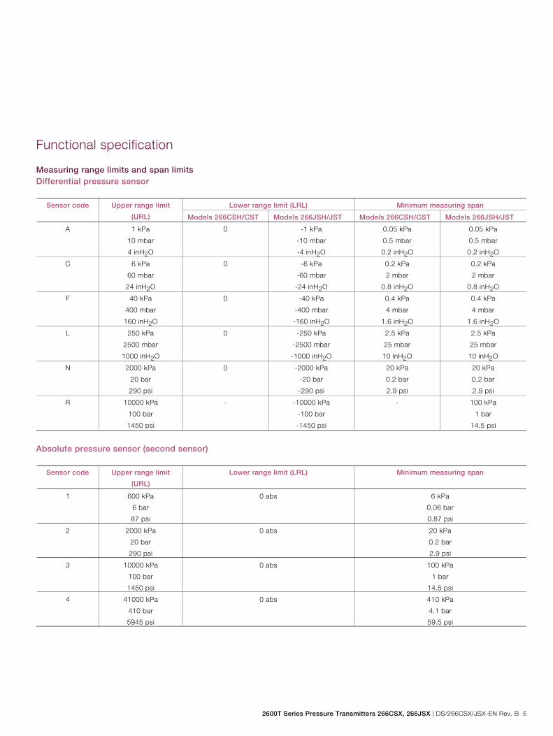
Functional specification
Measuring range limits and span limits Differential pressure sensor
Sensor code Upper range limit
(URL)
Lower range limit (LRL) Minimum measuring span
Models 266CSH/CST Models 266JSH/JST Models 266CSH/CST Models 266JSH/JST
A 1 kPa
10 mbar
4 inH2O
0 -1 kPa
-10 mbar
-4 inH2O
0.05 kPa
0.5 mbar
0.2 inH2O
0.05 kPa
0.5 mbar
0.2 inH2O
C 6 kPa
60 mbar
24 inH2O
0 -6 kPa
-60 mbar
-24 inH2O
0.2 kPa
2 mbar
0.8 inH2O
0.2 kPa
2 mbar
0.8 inH2O
F 40 kPa
400 mbar
160 inH2O
0 -40 kPa
-400 mbar
-160 inH2O
0.4 kPa
4 mbar
1.6 inH2O
0.4 kPa
4 mbar
1.6 inH2O
L 250 kPa
2500 mbar
1000 inH2O
0 -250 kPa
-2500 mbar
-1000 inH2O
2.5 kPa
25 mbar
10 inH2O
2.5 kPa
25 mbar
10 inH2O
N 2000 kPa
20 bar
290 psi
0 -2000 kPa
-20 bar
-290 psi
20 kPa
0.2 bar
2.9 psi
20 kPa
0.2 bar
2.9 psi
R 10000 kPa
100 bar
1450 psi
- -10000 kPa
-100 bar
-1450 psi
- 100 kPa
1 bar
14.5 psi
Absolute pressure sensor (second sensor)
Sensor code Upper range limit
(URL)
Lower range limit (LRL) Minimum measuring span
1 600 kPa
6 bar
87 psi
0 abs 6 kPa
0.06 bar
0.87 psi
2 2000 kPa
20 bar
290 psi
0 abs 20 kPa
0.2 bar
2.9 psi
3 10000 kPa
100 bar
1450 psi
0 abs 100 kPa
1 bar
14.5 psi
4 41000 kPa
410 bar
5945 psi
0 abs 410 kPa
4.1 bar
59.5 psi
Change from one to two columns
Model 266CSH/CST Multivariable Model 266JSH/JST Multivariable
6 DS/266CSX/JSX-EN Rev. B | 2600T Series Pressure Transmitters 266CSX, 266JSX
Span limits Maximum measuring span = URL (for differential pressure measurements, can be adjusted up to ± URL (TD = 0.5) within the measuring range limits) IMPORTANT (NOTICE) To optimize performance characteristics, it is recommended that you select the transmitter sensor code with the lowest turn down ratio. Recommendation for square root function At least 10 % of measuring range upper limit (URL) Zero position suppression and elevation The zero position and span can be set to any value within the measuring range limits listed in the table if: — already set span ≥ minimum span
Temperature input Process temperature range -200 ... 850 °C (-328 ... 1562 °F) with external resistance thermometer (Pt100) in four-wire circuit. Damping Configurable time constant between 0 and 60 s. This is in addition to the sensor response time. Warm-up time Ready for operation as per specifications in less than 10 s with minimum damping. Insulation resistance > 100 MΩ at 500 V DC (between terminals and ground)
2600T Series Pressure Transmitters 266CSX, 266JSX | DS/266CSX/JSX-EN Rev. B 7
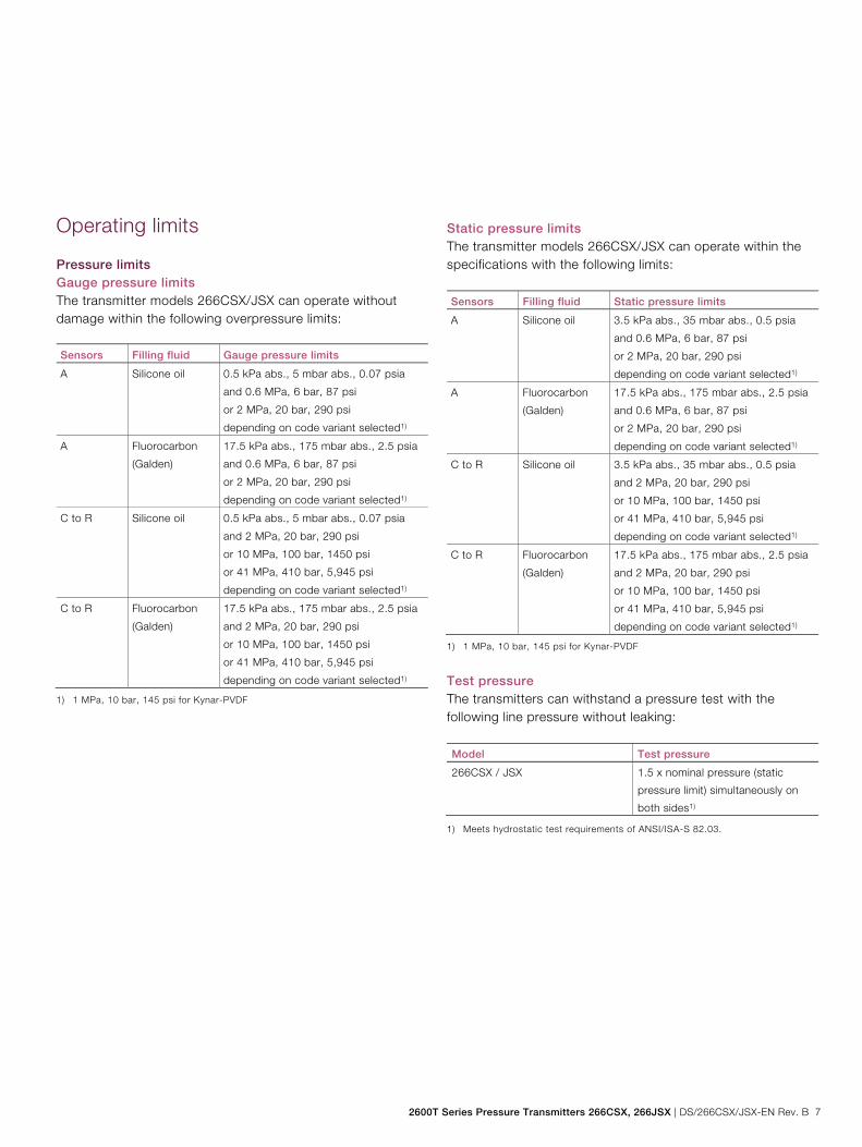
Operating limits
Pressure limits Gauge pressure limits The transmitter models 266CSX/JSX can operate without damage within the following overpressure limits: Sensors Filling fluid Gauge pressure limits
A Silicone oil 0.5 kPa abs., 5 mbar abs., 0.07 psia
and 0.6 MPa, 6 bar, 87 psi
or 2 MPa, 20 bar, 290 psi
depending on code variant selected1)
A Fluorocarbon
(Galden)
17.5 kPa abs., 175 mbar abs., 2.5 psia
and 0.6 MPa, 6 bar, 87 psi
or 2 MPa, 20 bar, 290 psi
depending on code variant selected1)
C to R Silicone oil 0.5 kPa abs., 5 mbar abs., 0.07 psia
and 2 MPa, 20 bar, 290 psi
or 10 MPa, 100 bar, 1450 psi
or 41 MPa, 410 bar, 5,945 psi
depending on code variant selected1)
C to R Fluorocarbon
(Galden)
17.5 kPa abs., 175 mbar abs., 2.5 psia
and 2 MPa, 20 bar, 290 psi
or 10 MPa, 100 bar, 1450 psi
or 41 MPa, 410 bar, 5,945 psi
depending on code variant selected1)
1) 1 MPa, 10 bar, 145 psi for Kynar-PVDF
Static pressure limits The transmitter models 266CSX/JSX can operate within the specifications with the following limits: Sensors Filling fluid Static pressure limits
A Silicone oil 3.5 kPa abs., 35 mbar abs., 0.5 psia
and 0.6 MPa, 6 bar, 87 psi
or 2 MPa, 20 bar, 290 psi
depending on code variant selected1)
A Fluorocarbon
(Galden)
17.5 kPa abs., 175 mbar abs., 2.5 psia
and 0.6 MPa, 6 bar, 87 psi
or 2 MPa, 20 bar, 290 psi
depending on code variant selected1)
C to R Silicone oil 3.5 kPa abs., 35 mbar abs., 0.5 psia
and 2 MPa, 20 bar, 290 psi
or 10 MPa, 100 bar, 1450 psi
or 41 MPa, 410 bar, 5,945 psi
depending on code variant selected1)
C to R Fluorocarbon
(Galden)
17.5 kPa abs., 175 mbar abs., 2.5 psia
and 2 MPa, 20 bar, 290 psi
or 10 MPa, 100 bar, 1450 psi
or 41 MPa, 410 bar, 5,945 psi
depending on code variant selected1)
1) 1 MPa, 10 bar, 145 psi for Kynar-PVDF
Test pressure The transmitters can withstand a pressure test with the following line pressure without leaking: Model Test pressure
266CSX / JSX 1.5 x nominal pressure (static
pressure limit) simultaneously on
both sides1)
1) Meets hydrostatic test requirements of ANSI/ISA-S 82.03.
Model 266CSH/CST Multivariable Model 266JSH/JST Multivariable
8 DS/266CSX/JSX-EN Rev. B | 2600T Series Pressure Transmitters 266CSX, 266JSX
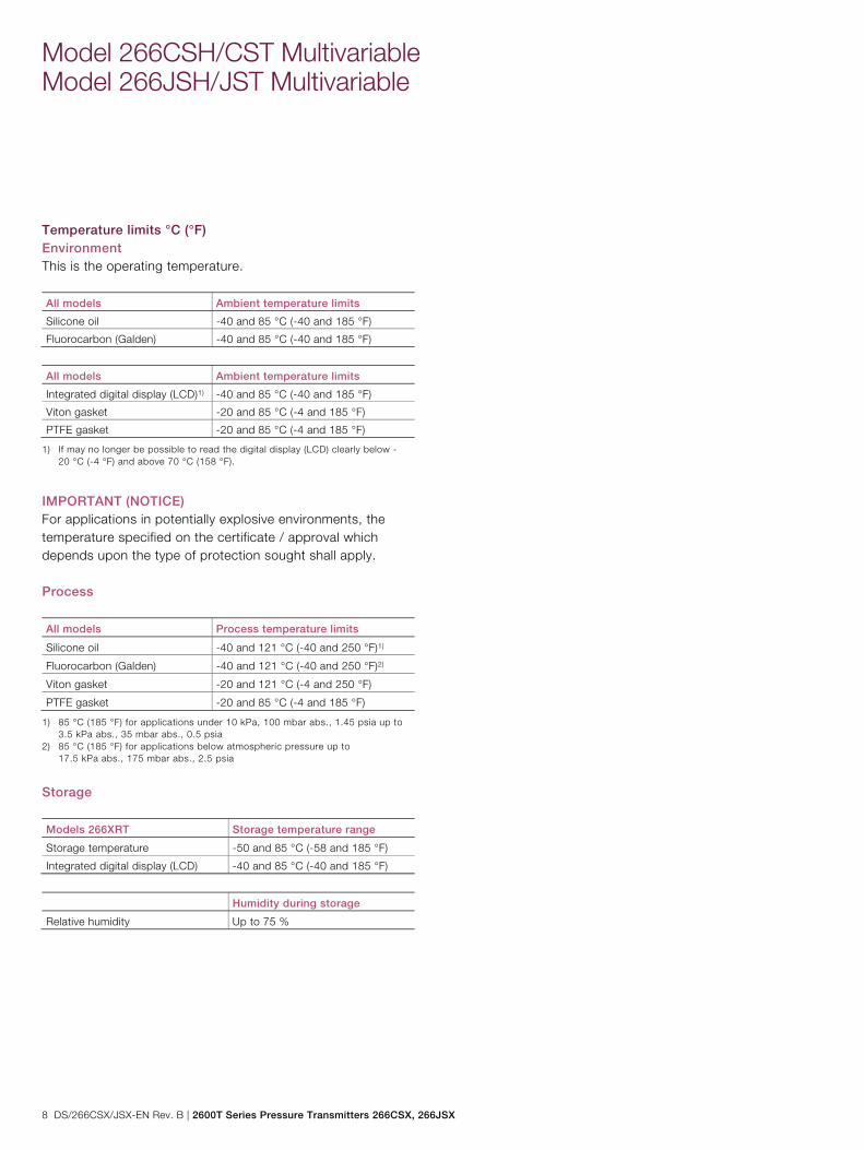
Temperature limits °C (°F) Environment This is the operating temperature. All models Ambient temperature limits
Silicone oil -40 and 85 °C (-40 and 185 °F)
Fluorocarbon (Galden) -40 and 85 °C (-40 and 185 °F)
All models Ambient temperature limits
Integrated digital display (LCD)1) -40 and 85 °C (-40 and 185 °F)
Viton gasket -20 and 85 °C (-4 and 185 °F)
PTFE gasket -20 and 85 °C (-4 and 185 °F)
1) If may no longer be possible to read the digital display (LCD) clearly below -20 °C (-4 °F) and above 70 °C (158 °F).
IMPORTANT (NOTICE) For applications in potentially explosive environments, the temperature specified on the certificate / approval which depends upon the type of protection sought shall apply. Process All models Process temperature limits
Silicone oil -40 and 121 °C (-40 and 250 °F)1)
Fluorocarbon (Galden) -40 and 121 °C (-40 and 250 °F)2)
Viton gasket -20 and 121 °C (-4 and 250 °F)
PTFE gasket -20 and 85 °C (-4 and 185 °F)
1) 85 °C (185 °F) for applications under 10 kPa, 100 mbar abs., 1.45 psia up to 3.5 kPa abs., 35 mbar abs., 0.5 psia
2) 85 °C (185 °F) for applications below atmospheric pressure up to 17.5 kPa abs., 175 mbar abs., 2.5 psia
Storage Models 266XRT Storage temperature range
Storage temperature -50 and 85 °C (-58 and 185 °F)
Integrated digital display (LCD) -40 and 85 °C (-40 and 185 °F)
Humidity during storage
Relative humidity Up to 75 %
2600T Series Pressure Transmitters 266CSX, 266JSX | DS/266CSX/JSX-EN Rev. B 9
Environmental limits
Electromagnetic compatibility (EMC) In accordance with EN 61326 Overvoltage strength (with overvoltage protection): 4 kV (in accordance with IEC 1000-4-5 EN 61000-4-5) Pressure Equipment Directive (PED) Instruments with a maximum operating pressure of 41 MPa, 410 bar, 5,945 psi comply with Directive 2014/68/EU category III, module H. Humidity Relative humidity: up to 100 %. Condensation, icing: permitted. Vibration resistance Acceleration up to 2 g at frequencies of up to 1000 Hz (in accordance with IEC 60068-2-6). Shock resistance Acceleration: 50 g Duration: 11 ms (in accordance with IEC 60068-2-27). Humid and dusty atmospheres (IP rating) The transmitter is dust and sand-proof and protected against immersion effects in accordance with EN 60529 (2001) with IP 67 (IP 68 on request), by NEMA 4X, or by JIS C0920.
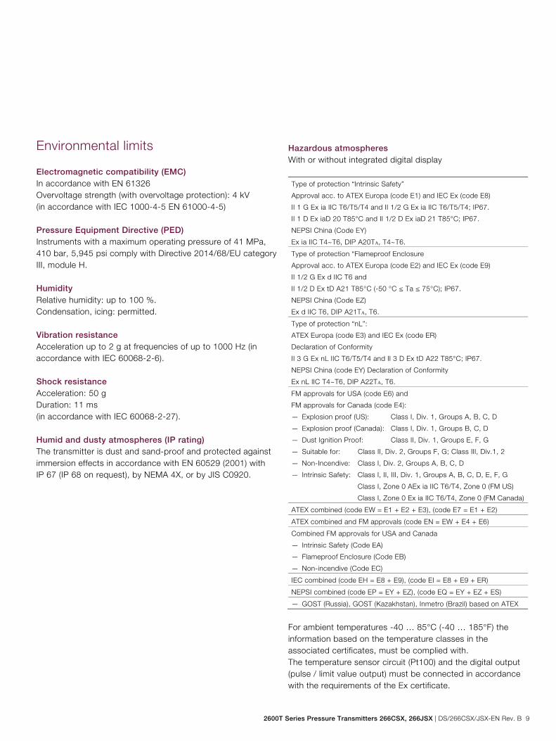
Hazardous atmospheres With or without integrated digital display Type of protection “Intrinsic Safety”
Approval acc. to ATEX Europa (code E1) and IEC Ex (code E8)
II 1 G Ex ia IIC T6/T5/T4 and II 1/2 G Ex ia IIC T6/T5/T4; IP67.
II 1 D Ex iaD 20 T85°C and II 1/2 D Ex iaD 21 T85°C; IP67.
NEPSI China (Code EY)
Ex ia IIC T4~T6, DIP A20TA, T4~T6. Type of protection “Flameproof Enclosure
Approval acc. to ATEX Europa (code E2) and IEC Ex (code E9)
II 1/2 G Ex d IIC T6 and
II 1/2 D Ex tD A21 T85°C (-50 °C ≤ Ta ≤ 75°C); IP67.
NEPSI China (Code EZ)
Ex d IIC T6, DIP A21TA, T6.
Type of protection “nL”:
ATEX Europa (code E3) and IEC Ex (code ER)
Declaration of Conformity
II 3 G Ex nL IIC T6/T5/T4 and II 3 D Ex tD A22 T85°C; IP67.
NEPSI China (code EY) Declaration of Conformity
Ex nL IIC T4~T6, DIP A22TA, T6.
FM approvals for USA (code E6) and
FM approvals for Canada (code E4):
— Explosion proof (US): Class I, Div. 1, Groups A, B, C, D
— Explosion proof (Canada): Class I, Div. 1, Groups B, C, D
— Dust Ignition Proof: Class II, Div. 1, Groups E, F, G
— Suitable for: Class II, Div. 2, Groups F, G; Class III, Div.1, 2
— Non-Incendive: Class I, Div. 2, Groups A, B, C, D
— Intrinsic Safety: Class I, II, III, Div. 1, Groups A, B, C, D, E, F, G
Class I, Zone 0 AEx ia IIC T6/T4, Zone 0 (FM US)
Class I, Zone 0 Ex ia IIC T6/T4, Zone 0 (FM Canada)
ATEX combined (code EW = E1 + E2 + E3), (code E7 = E1 + E2)
ATEX combined and FM approvals (code EN = EW + E4 + E6)
Combined FM approvals for USA and Canada
— Intrinsic Safety (Code EA)
— Flameproof Enclosure (Code EB)
— Non-incendive (Code EC)
IEC combined (code EH = E8 + E9), (code EI = E8 + E9 + ER)
NEPSI combined (code EP = EY + EZ), (code EQ = EY + EZ + ES)
— GOST (Russia), GOST (Kazakhstan), Inmetro (Brazil) based on ATEX
For ambient temperatures -40 … 85°C (-40 … 185°F) the information based on the temperature classes in the associated certificates, must be complied with. The temperature sensor circuit (Pt100) and the digital output (pulse / limit value output) must be connected in accordance with the requirements of the Ex certificate.
Model 266CSH/CST Multivariable Model 266JSH/JST Multivariable
10 DS/266CSX/JSX-EN Rev. B | 2600T Series Pressure Transmitters 266CSX, 266JSX
Electrical data and options
Power supply The transmitter operates from 10.5 … 42 V DC with no load and is protected against reversed polarity (additional loads enable operation above 42 V DC). During use in Ex ia zones and in other intrinsically safe applications, the power supply must not exceed 30 V DC. Ripple Max. 20 mV over a 250 Ω load in accordance with HART specifications. Load limitations Total loop resistance at 4 ... 20 mA and HART:
mAVDCvoltageoperatingMinimumvoltageSupplykR
22)(
)(
Ω
A minimum resistance of 250 Ω is required for HART communication. Displays (optional) Integrated LCD display (code L1) Wide-screen LCD display, 128 x 64 pixels, 52.5 x 27.2 mm (2.06 x 1.07 in.) dot matrix. Multilingual. Four keys for device configuration and management. Easy setup for quick commissioning. Customized visualizations which the user can select. Total value and actual value flow indication. The LCD display can also be used to show static pressure, sensor temperature, and diagnostics messages, as well as make configuration settings.
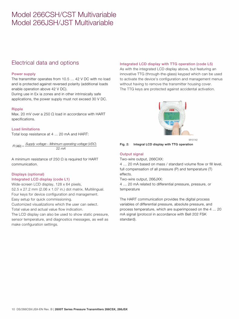
Integrated LCD display with TTG operation (code L5) As with the integrated LCD display above, but featuring an innovative TTG (through-the-glass) keypad which can be used to activate the device's configuration and management menus without having to remove the transmitter housing cover. The TTG keys are protected against accidental activation.
Fig. 2: Integral LCD display with TTG operation
Output signal Two-wire output, 266CXX: 4 … 20 mA based on mass / standard volume flow or fill level, full compensation of all pressure (P) and temperature (T) effects. Two-wire output, 266JXX: 4 … 20 mA related to differential pressure, pressure, or temperature The HART communication provides the digital process variables of differential pressure, absolute pressure, and process temperature, which are superimposed on the 4 ... 20 mA signal (protocol in accordance with Bell 202 FSK standard).
2600T Series Pressure Transmitters 266CSX, 266JSX | DS/266CSX/JSX-EN Rev. B 11
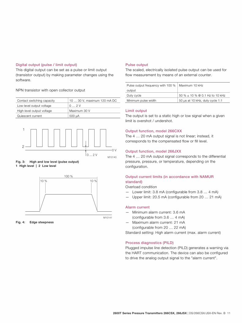
Digital output (pulse / limit output) This digital output can be set as a pulse or limit output (transistor output) by making parameter changes using the software. NPN transistor with open collector output Contact switching capacity 10 … 30 V, maximum 120 mA DC Low-level output voltage 0 … 2 V High-level output voltage Maximum 30 V Quiescent current 500 μA
Fig. 3: High and low level (pulse output) 1 High level | 2 Low level
Fig. 4: Edge steepness
Pulse output The scaled, electrically isolated pulse output can be used for flow measurement by means of an external counter. Pulse output frequency with 100 %
output Maximum 10 kHz
Duty cycle 50 % ± 10 % @ 0.1 Hz to 10 kHz Minimum pulse width 50 μs at 10 kHz, duty cycle 1:1
Limit output The output is set to a static high or low signal when a given limit is overshot / undershot. Output function, model 266CXX The 4 … 20 mA output signal is not linear; instead, it corresponds to the compensated flow or fill level. Output function, model 266JXX The 4 … 20 mA output signal corresponds to the differential pressure, pressure, or temperature, depending on the configuration. Output current limits (in accordance with NAMUR standard) Overload condition — Lower limit: 3.8 mA (configurable from 3.8 … 4 mA) — Upper limit: 20.5 mA (configurable from 20 … 21 mA) Alarm current — Minimum alarm current: 3.6 mA (configurable from 3.6 … 4 mA) — Maximum alarm current: 21 mA (configurable from 20 … 22 mA) Standard setting: High alarm current (max. alarm current) Process diagnostics (PILD) Plugged impulse line detection (PILD) generates a warning via the HART communication. The device can also be configured to drive the analog output signal to the "alarm current".
Model 266CSH/CST Multivariable Model 266JSH/JST Multivariable
12 DS/266CSX/JSX-EN Rev. B | 2600T Series Pressure Transmitters 266CSX, 266JSX
Measuring accuracy
Reference conditions according to IEC 60770 Ambient temperature 20 °C (68 °F), rel. humidity 65 %, atmospheric pressure 1,013 hPa (1,013 mbar), position of measuring cell (separating diaphragm areas) vertical, measuring span based on zero point, separating diaphragms made from stainless steel AISI 316 L or Hastelloy, silicone oil filling fluid, HART digital trim values equal to 4 and 20 mA span end points. Unless otherwise stated, errors are specified as a % of the measuring span value. Some measuring accuracy levels relating to the upper measuring range limit (URL) are affected by the current turn down (TD); i.e., the ratio of the upper measuring range limit to the already set span. FOR OPTIMUM MEASURING ACCURACY, IT IS RECOMMENDED THAT YOU SELECT THE SENSOR CODE WHICH WILL PROVIDE THE LOWEST TD VALUE. Dynamic response (in accordance with IEC 61298-1) Sensors Time constant
(63.2 % of total step response)
Sensors F to R 150 ms
Sensor C 400 ms
Sensor A 1000 ms
266CXX: Delay time for
all sensors
70 ms
266JXX: Delay time for
all sensors
40 ms
Response time (total) = delay time + time constant
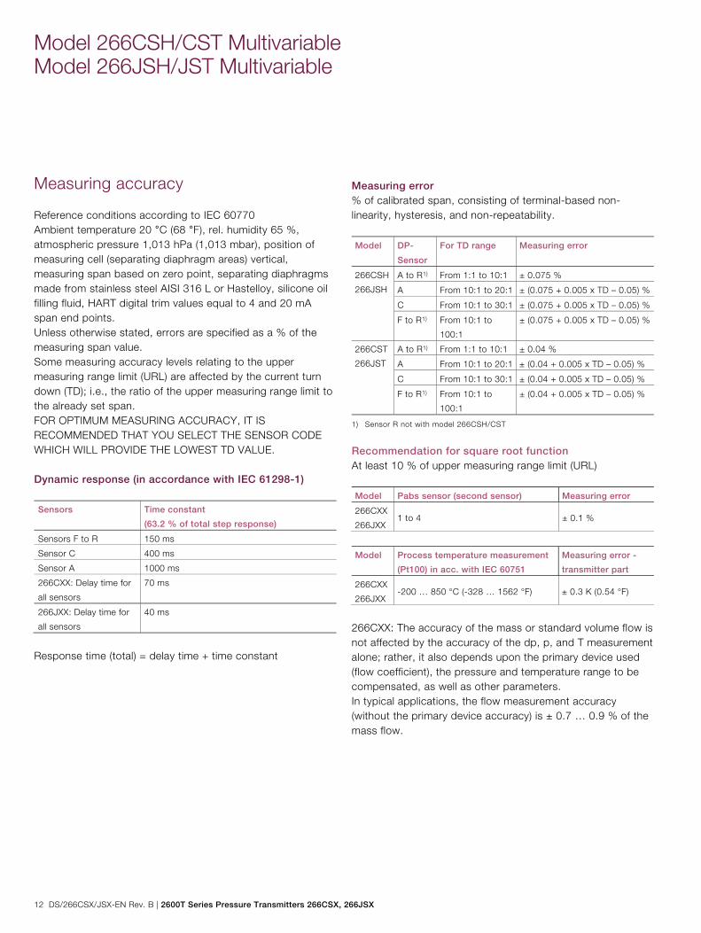
Measuring error % of calibrated span, consisting of terminal-based non-linearity, hysteresis, and non-repeatability. Model DP-
Sensor
For TD range Measuring error
266CSH
266JSH
A to R1) From 1:1 to 10:1 ± 0.075 %
A From 10:1 to 20:1 ± (0.075 + 0.005 x TD – 0.05) %
C From 10:1 to 30:1 ± (0.075 + 0.005 x TD – 0.05) %
F to R1) From 10:1 to
100:1
± (0.075 + 0.005 x TD – 0.05) %
266CST
266JST
A to R1) From 1:1 to 10:1 ± 0.04 %
A From 10:1 to 20:1 ± (0.04 + 0.005 x TD – 0.05) %
C From 10:1 to 30:1 ± (0.04 + 0.005 x TD – 0.05) %
F to R1) From 10:1 to
100:1
± (0.04 + 0.005 x TD – 0.05) %
1) Sensor R not with model 266CSH/CST
Recommendation for square root function At least 10 % of upper measuring range limit (URL) Model Pabs sensor (second sensor) Measuring error
266CXX
266JXX 1 to 4 ± 0.1 %
Model Process temperature measurement
(Pt100) in acc. with IEC 60751
Measuring error -
transmitter part
266CXX
266JXX -200 … 850 °C (-328 … 1562 °F) ± 0.3 K (0.54 °F)
266CXX: The accuracy of the mass or standard volume flow is not affected by the accuracy of the dp, p, and T measurement alone; rather, it also depends upon the primary device used (flow coefficient), the pressure and temperature range to be compensated, as well as other parameters. In typical applications, the flow measurement accuracy (without the primary device accuracy) is ± 0.7 … 0.9 % of the mass flow.
2600T Series Pressure Transmitters 266CSX, 266JSX | DS/266CSX/JSX-EN Rev. B 13
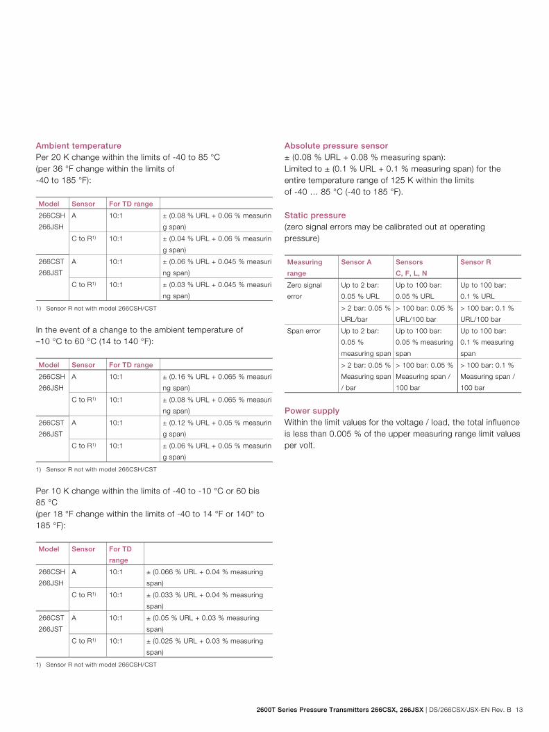
Ambient temperature Per 20 K change within the limits of -40 to 85 °C (per 36 °F change within the limits of -40 to 185 °F): Model Sensor For TD range
266CSH
266JSH
A 10:1 ± (0.08 % URL + 0.06 % measurin
g span)
C to R1) 10:1 ± (0.04 % URL + 0.06 % measurin
g span)
266CST
266JST
A 10:1 ± (0.06 % URL + 0.045 % measuri
ng span)
C to R1) 10:1 ± (0.03 % URL + 0.045 % measuri
ng span)
1) Sensor R not with model 266CSH/CST
In the event of a change to the ambient temperature of –10 °C to 60 °C (14 to 140 °F): Model Sensor For TD range
266CSH
266JSH
A 10:1 ± (0.16 % URL + 0.065 % measuri
ng span)
C to R1) 10:1 ± (0.08 % URL + 0.065 % measuri
ng span)
266CST
266JST
A 10:1 ± (0.12 % URL + 0.05 % measurin
g span)
C to R1) 10:1 ± (0.06 % URL + 0.05 % measurin
g span)
1) Sensor R not with model 266CSH/CST
Per 10 K change within the limits of -40 to -10 °C or 60 bis 85 °C (per 18 °F change within the limits of -40 to 14 °F or 140° to 185 °F): Model Sensor For TD
range
266CSH
266JSH
A 10:1 ± (0.066 % URL + 0.04 % measuring
span)
C to R1) 10:1 ± (0.033 % URL + 0.04 % measuring
span)
266CST
266JST
A 10:1 ± (0.05 % URL + 0.03 % measuring
span)
C to R1) 10:1 ± (0.025 % URL + 0.03 % measuring
span)
1) Sensor R not with model 266CSH/CST
Absolute pressure sensor ± (0.08 % URL + 0.08 % measuring span): Limited to ± (0.1 % URL + 0.1 % measuring span) for the entire temperature range of 125 K within the limits of -40 … 85 °C (-40 to 185 °F). Static pressure (zero signal errors may be calibrated out at operating pressure) Measuring
range
Sensor A Sensors
C, F, L, N
Sensor R
Zero signal
error
Up to 2 bar:
0.05 % URL
Up to 100 bar:
0.05 % URL
Up to 100 bar:
0.1 % URL
> 2 bar: 0.05 %
URL/bar
> 100 bar: 0.05 %
URL/100 bar
> 100 bar: 0.1 %
URL/100 bar
Span error Up to 2 bar:
0.05 %
measuring span
Up to 100 bar:
0.05 % measuring
span
Up to 100 bar:
0.1 % measuring
span
> 2 bar: 0.05 %
Measuring span
/ bar
> 100 bar: 0.05 %
Measuring span /
100 bar
> 100 bar: 0.1 %
Measuring span /
100 bar
Power supply Within the limit values for the voltage / load, the total influence is less than 0.005 % of the upper measuring range limit values per volt.
Model 266CSH/CST Multivariable Model 266JSH/JST Multivariable
14 DS/266CSX/JSX-EN Rev. B | 2600T Series Pressure Transmitters 266CSX, 266JSX
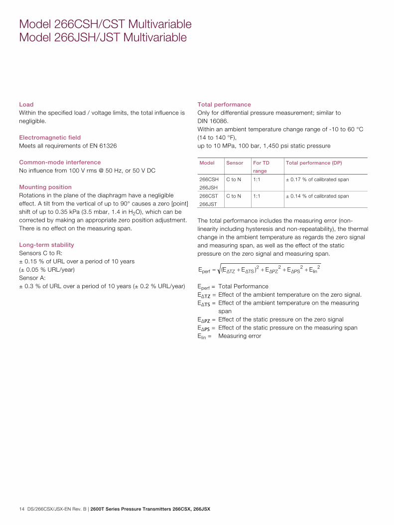
Load Within the specified load / voltage limits, the total influence is negligible. Electromagnetic field Meets all requirements of EN 61326 Common-mode interference No influence from 100 V rms @ 50 Hz, or 50 V DC Mounting position Rotations in the plane of the diaphragm have a negligible effect. A tilt from the vertical of up to 90° causes a zero [point] shift of up to 0.35 kPa (3.5 mbar, 1.4 in H2O), which can be corrected by making an appropriate zero position adjustment. There is no effect on the measuring span. Long-term stability Sensors C to R: ± 0.15 % of URL over a period of 10 years (± 0.05 % URL/year) Sensor A: ± 0.3 % of URL over a period of 10 years (± 0.2 % URL/year)
Total performance Only for differential pressure measurement; similar to DIN 16086. Within an ambient temperature change range of -10 to 60 °C (14 to 140 °F), up to 10 MPa, 100 bar, 1,450 psi static pressure Model Sensor For TD
range
Total performance (DP)
266CSH
266JSH
C to N 1:1 ± 0.17 % of calibrated span
266CST
266JST
C to N 1:1 ± 0.14 % of calibrated span
The total performance includes the measuring error (non-linearity including hysteresis and non-repeatability), the thermal change in the ambient temperature as regards the zero signal and measuring span, as well as the effect of the static pressure on the zero signal and measuring span.
2lin
2PSΔ
2PZΔ
2TSΔTZΔperf EEE)EE(E
Eperf = Total Performance EΔTZ = Effect of the ambient temperature on the zero signal. EΔTS = Effect of the ambient temperature on the measuring
span EΔPZ = Effect of the static pressure on the zero signal EΔPS = Effect of the static pressure on the measuring span Elin = Measuring error
2600T Series Pressure Transmitters 266CSX, 266JSX | DS/266CSX/JSX-EN Rev. B 15
Technical specification
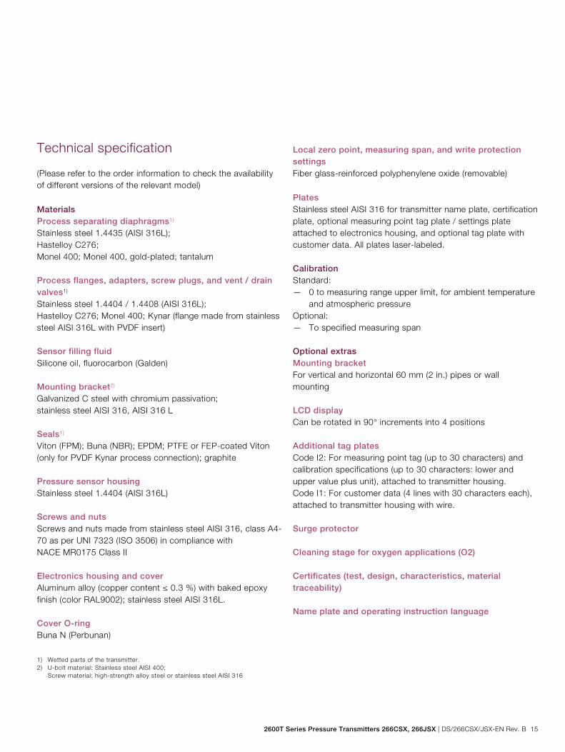
(Please refer to the order information to check the availability of different versions of the relevant model) Materials Process separating diaphragms1) Stainless steel 1.4435 (AISI 316L); Hastelloy C276; Monel 400; Monel 400, gold-plated; tantalum Process flanges, adapters, screw plugs, and vent / drain valves1) Stainless steel 1.4404 / 1.4408 (AISI 316L); Hastelloy C276; Monel 400; Kynar (flange made from stainless steel AISI 316L with PVDF insert) Sensor filling fluid Silicone oil, fluorocarbon (Galden) Mounting bracket2) Galvanized C steel with chromium passivation; stainless steel AISI 316, AISI 316 L Seals1) Viton (FPM); Buna (NBR); EPDM; PTFE or FEP-coated Viton (only for PVDF Kynar process connection); graphite Pressure sensor housing Stainless steel 1.4404 (AISI 316L) Screws and nuts Screws and nuts made from stainless steel AISI 316, class A4-70 as per UNI 7323 (ISO 3506) in compliance with NACE MR0175 Class II Electronics housing and cover Aluminum alloy (copper content ≤ 0.3 %) with baked epoxy finish (color RAL9002); stainless steel AISI 316L. Cover O-ring Buna N (Perbunan)
1) Wetted parts of the transmitter. 2) U-bolt material: Stainless steel AISI 400; Screw material: high-strength alloy steel or stainless steel AISI 316
Local zero point, measuring span, and write protection settings Fiber glass-reinforced polyphenylene oxide (removable) Plates Stainless steel AISI 316 for transmitter name plate, certification plate, optional measuring point tag plate / settings plate attached to electronics housing, and optional tag plate with customer data. All plates laser-labeled. Calibration Standard: — 0 to measuring range upper limit, for ambient temperature
and atmospheric pressure Optional: — To specified measuring span Optional extras Mounting bracket For vertical and horizontal 60 mm (2 in.) pipes or wall mounting LCD display Can be rotated in 90° increments into 4 positions Additional tag plates Code I2: For measuring point tag (up to 30 characters) and calibration specifications (up to 30 characters: lower and upper value plus unit), attached to transmitter housing. Code I1: For customer data (4 lines with 30 characters each), attached to transmitter housing with wire. Surge protector Cleaning stage for oxygen applications (O2) Certificates (test, design, characteristics, material traceability) Name plate and operating instruction language
Model 266CSH/CST Multivariable Model 266JSH/JST Multivariable
16 DS/266CSX/JSX-EN Rev. B | 2600T Series Pressure Transmitters 266CSX, 266JSX
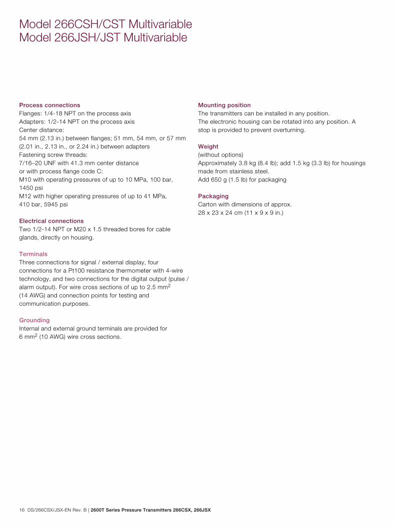
Process connections Flanges: 1/4-18 NPT on the process axis Adapters: 1/2-14 NPT on the process axis Center distance: 54 mm (2.13 in.) between flanges; 51 mm, 54 mm, or 57 mm (2.01 in., 2.13 in., or 2.24 in.) between adapters Fastening screw threads: 7/16–20 UNF with 41.3 mm center distance or with process flange code C: M10 with operating pressures of up to 10 MPa, 100 bar, 1450 psi M12 with higher operating pressures of up to 41 MPa, 410 bar, 5945 psi Electrical connections Two 1/2-14 NPT or M20 x 1.5 threaded bores for cable glands, directly on housing. Terminals Three connections for signal / external display, four connections for a Pt100 resistance thermometer with 4-wire technology, and two connections for the digital output (pulse / alarm output). For wire cross sections of up to 2.5 mm2 (14 AWG) and connection points for testing and communication purposes. Grounding Internal and external ground terminals are provided for 6 mm2 (10 AWG) wire cross sections.
Mounting position The transmitters can be installed in any position. The electronic housing can be rotated into any position. A stop is provided to prevent overturning. Weight (without options) Approximately 3.8 kg (8.4 lb); add 1.5 kg (3.3 lb) for housings made from stainless steel. Add 650 g (1.5 lb) for packaging Packaging Carton with dimensions of approx. 28 x 23 x 24 cm (11 x 9 x 9 in.)
2600T Series Pressure Transmitters 266CSX, 266JSX | DS/266CSX/JSX-EN Rev. B 17
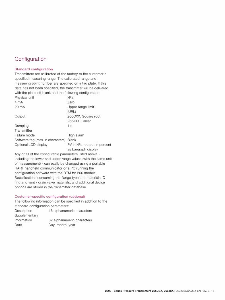
Configuration
Standard configuration Transmitters are calibrated at the factory to the customer's specified measuring range. The calibrated range and measuring point number are specified on a tag plate. If this data has not been specified, the transmitter will be delivered with the plate left blank and the following configuration: Physical unit kPa 4 mA Zero 20 mA Upper range limit (URL) Output 266CXX: Square root 266JXX: Linear Damping 1 s Transmitter Failure mode High alarm Software tag (max. 8 characters) Blank Optional LCD display PV in kPa; output in percent
as bargraph display Any or all of the configurable parameters listed above - including the lower and upper range values (with the same unit of measurement) - can easily be changed using a portable HART handheld communicator or a PC running the configuration software with the DTM for 266 models. Specifications concerning the flange type and materials, O-ring and vent / drain valve materials, and additional device options are stored in the transmitter database. Customer-specific configuration (optional) The following information can be specified in addition to the standard configuration parameters: Description 16 alphanumeric characters Supplementary information 32 alphanumeric characters Date Day, month, year
Change from two to one column
Model 266CSH/CST Multivariable Model 266JSH/JST Multivariable
18 DS/266CSX/JSX-EN Rev. B | 2600T Series Pressure Transmitters 266CSX, 266JSX
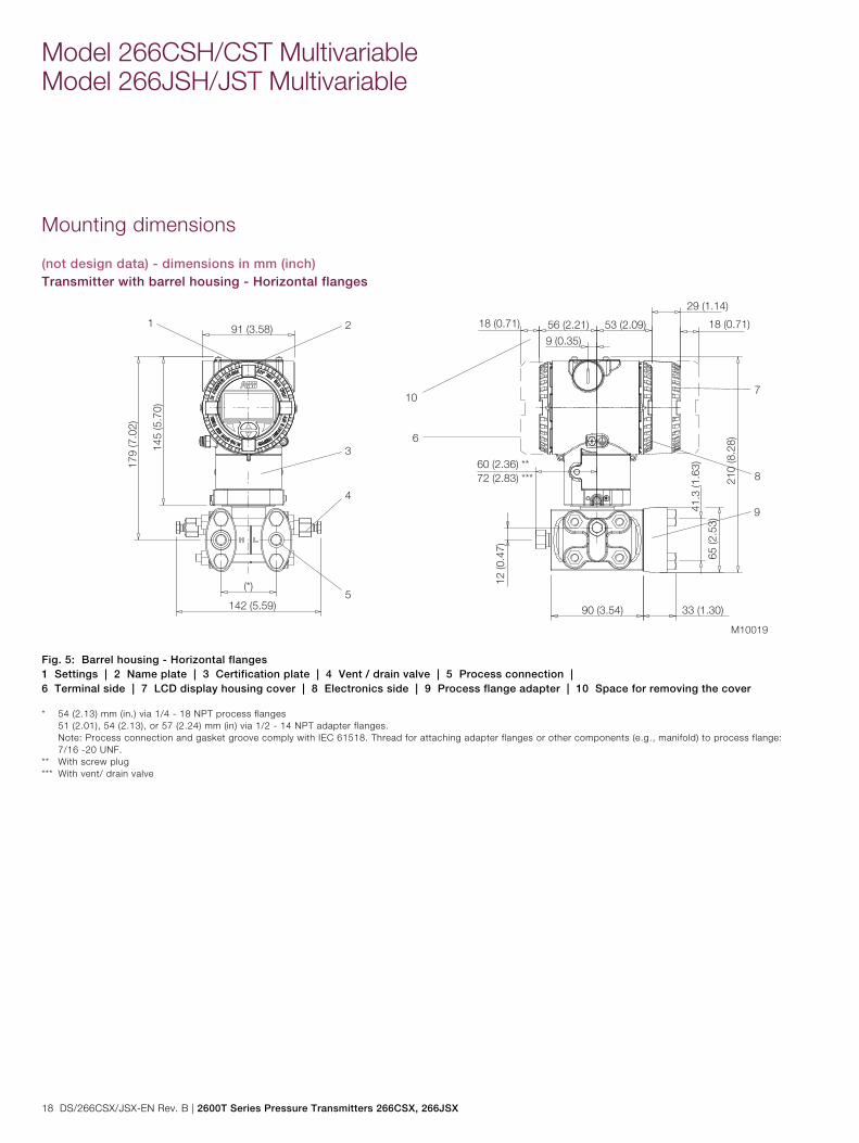
Mounting dimensions
(not design data) - dimensions in mm (inch) Transmitter with barrel housing - Horizontal flanges
Fig. 5: Barrel housing - Horizontal flanges 1 Settings | 2 Name plate | 3 Certification plate | 4 Vent / drain valve | 5 Process connection | 6 Terminal side | 7 LCD display housing cover | 8 Electronics side | 9 Process flange adapter | 10 Space for removing the cover * 54 (2.13) mm (in.) via 1/4 - 18 NPT process flanges 51 (2.01), 54 (2.13), or 57 (2.24) mm (in) via 1/2 - 14 NPT adapter flanges. Note: Process connection and gasket groove comply with IEC 61518. Thread for attaching adapter flanges or other components (e.g., manifold) to process flange:
7/16 -20 UNF. ** With screw plug *** With vent/ drain valve
2600T Series Pressure Transmitters 266CSX, 266JSX | DS/266CSX/JSX-EN Rev. B 19
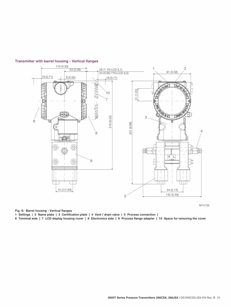
Transmitter with barrel housing - Vertical flanges
Fig. 6: Barrel housing - Vertical flanges 1 Settings | 2 Name plate | 3 Certification plate | 4 Vent / drain valve | 5 Process connection | 6 Terminal side | 7 LCD display housing cover | 8 Electronics side | 9 Process flange adapter | 10 Space for removing the cover
Model 266CSH/CST Multivariable Model 266JSH/JST Multivariable
20 DS/266CSX/JSX-EN Rev. B | 2600T Series Pressure Transmitters 266CSX, 266JSX
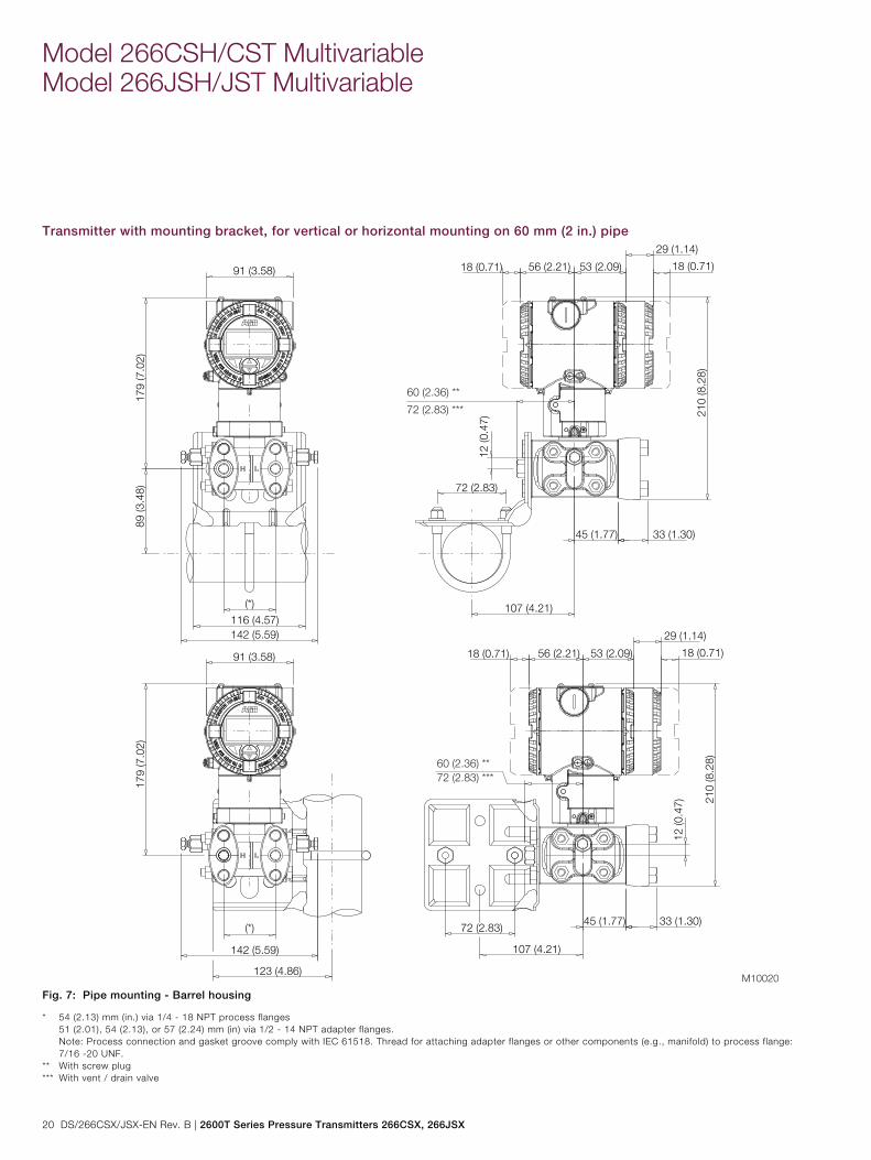
Transmitter with mounting bracket, for vertical or horizontal mounting on 60 mm (2 in.) pipe
Fig. 7: Pipe mounting - Barrel housing
* 54 (2.13) mm (in.) via 1/4 - 18 NPT process flanges 51 (2.01), 54 (2.13), or 57 (2.24) mm (in) via 1/2 - 14 NPT adapter flanges. Note: Process connection and gasket groove comply with IEC 61518. Thread for attaching adapter flanges or other components (e.g., manifold) to process flange:
7/16 -20 UNF. ** With screw plug *** With vent / drain valve
2600T Series Pressure Transmitters 266CSX, 266JSX | DS/266CSX/JSX-EN Rev. B 21
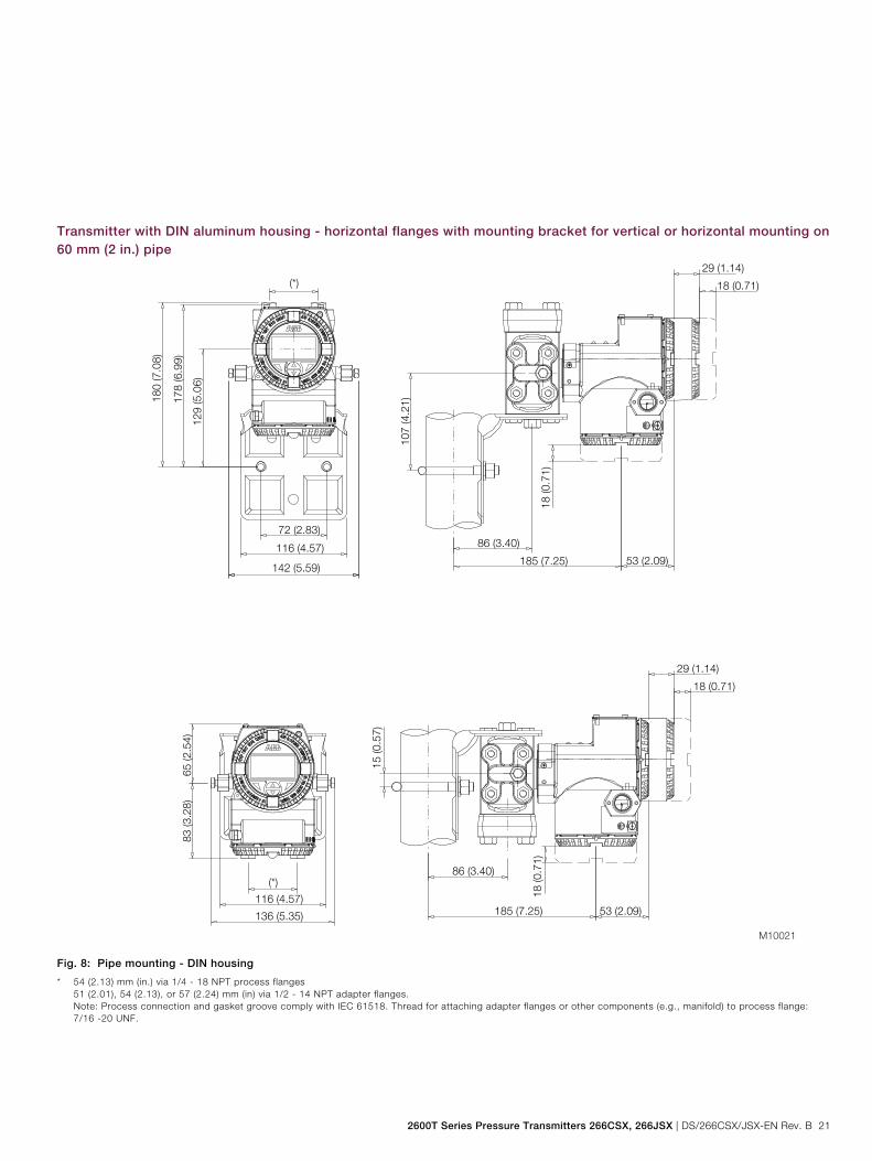
Transmitter with DIN aluminum housing - horizontal flanges with mounting bracket for vertical or horizontal mounting on 60 mm (2 in.) pipe
Fig. 8: Pipe mounting - DIN housing
* 54 (2.13) mm (in.) via 1/4 - 18 NPT process flanges 51 (2.01), 54 (2.13), or 57 (2.24) mm (in) via 1/2 - 14 NPT adapter flanges. Note: Process connection and gasket groove comply with IEC 61518. Thread for attaching adapter flanges or other components (e.g., manifold) to process flange:
7/16 -20 UNF.
Model 266CSH/CST Multivariable Model 266JSH/JST Multivariable
22 DS/266CSX/JSX-EN Rev. B | 2600T Series Pressure Transmitters 266CSX, 266JSX
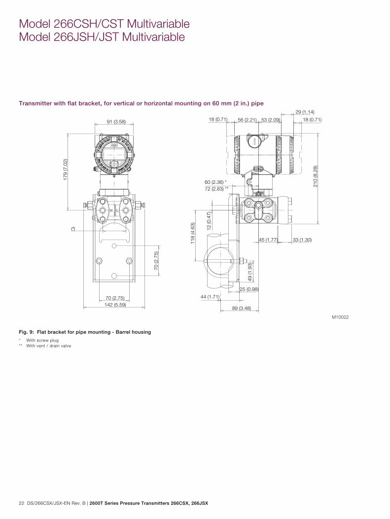
Transmitter with flat bracket, for vertical or horizontal mounting on 60 mm (2 in.) pipe
Fig. 9: Flat bracket for pipe mounting - Barrel housing
* With screw plug ** With vent / drain valve
2600T Series Pressure Transmitters 266CSX, 266JSX | DS/266CSX/JSX-EN Rev. B 23
Electrical connections
M10137
+ DIGITAL OUTPUT
PWR /COMM.
TEST
+
EXT.METER +
1
RTD
2 3 4
P/
N:X
XXX
USEWIRINGRATED5 °C MIN5 °C MIN. ABOVE MAXABOVE MAX.AMBIENTAMBIENTTEMPERATURE
Kent-Taylor
0
43
56 7 8
9
10
2040
0
60
100%
2 80
+
+ -
-
-
+M
-
+
5
7
4
6
3
2
1
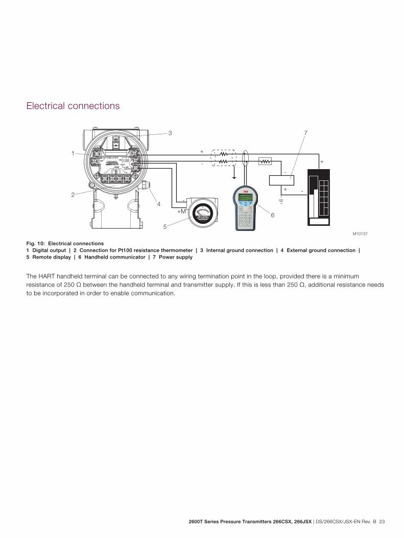
Fig. 10: Electrical connections 1 Digital output | 2 Connection for Pt100 resistance thermometer | 3 Internal ground connection | 4 External ground connection | 5 Remote display | 6 Handheld communicator | 7 Power supply
The HART handheld terminal can be connected to any wiring termination point in the loop, provided there is a minimum resistance of 250 Ω between the handheld terminal and transmitter supply. If this is less than 250 Ω, additional resistance needs to be incorporated in order to enable communication.
Model 266CSH/CST Multivariable Model 266JSH/JST Multivariable
24 DS/266CSX/JSX-EN Rev. B | 2600T Series Pressure Transmitters 266CSX, 266JSX
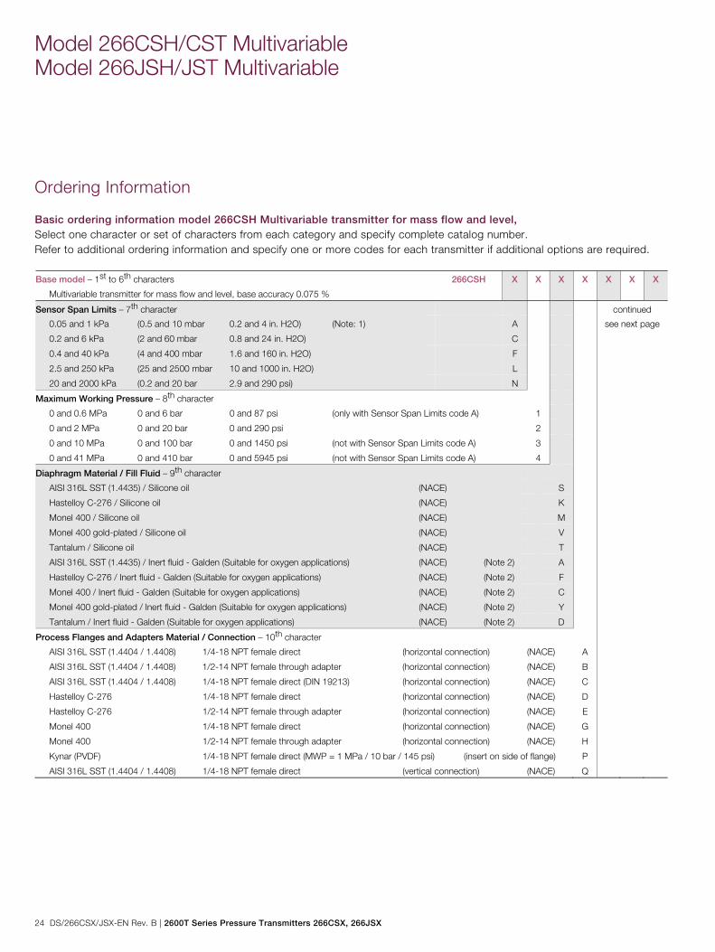
Ordering Information
Basic ordering information model 266CSH Multivariable transmitter for mass flow and level, Select one character or set of characters from each category and specify complete catalog number. Refer to additional ordering information and specify one or more codes for each transmitter if additional options are required. Base model – 1st to 6th characters
Multivariable transmitter for mass flow and level, base accuracy 0.075 %
266CSH X X X X X X X
Sensor Span Limits – 7th character continued
0.05 and 1 kPa (0.5 and 10 mbar 0.2 and 4 in. H2O) (Note: 1) A see next page
0.2 and 6 kPa (2 and 60 mbar 0.8 and 24 in. H2O) C
0.4 and 40 kPa (4 and 400 mbar 1.6 and 160 in. H2O) F
2.5 and 250 kPa (25 and 2500 mbar 10 and 1000 in. H2O) L
20 and 2000 kPa (0.2 and 20 bar 2.9 and 290 psi) N
Maximum Working Pressure – 8th character
0 and 0.6 MPa 0 and 6 bar 0 and 87 psi (only with Sensor Span Limits code A) 1
0 and 2 MPa 0 and 20 bar 0 and 290 psi 2
0 and 10 MPa 0 and 100 bar 0 and 1450 psi (not with Sensor Span Limits code A) 3
0 and 41 MPa 0 and 410 bar 0 and 5945 psi (not with Sensor Span Limits code A) 4
Diaphragm Material / Fill Fluid – 9th character
AISI 316L SST (1.4435) / Silicone oil (NACE) S
Hastelloy C-276 / Silicone oil (NACE) K
Monel 400 / Silicone oil (NACE) M
Monel 400 gold-plated / Silicone oil (NACE) V
Tantalum / Silicone oil (NACE) T
AISI 316L SST (1.4435) / Inert fluid - Galden (Suitable for oxygen applications) (NACE) (Note 2) A
Hastelloy C-276 / Inert fluid - Galden (Suitable for oxygen applications) (NACE) (Note 2) F
Monel 400 / Inert fluid - Galden (Suitable for oxygen applications) (NACE) (Note 2) C
Monel 400 gold-plated / Inert fluid - Galden (Suitable for oxygen applications) (NACE) (Note 2) Y
Tantalum / Inert fluid - Galden (Suitable for oxygen applications) (NACE) (Note 2) D
Process Flanges and Adapters Material / Connection – 10th character
AISI 316L SST (1.4404 / 1.4408) 1/4-18 NPT female direct (horizontal connection) (NACE) A
AISI 316L SST (1.4404 / 1.4408) 1/2-14 NPT female through adapter (horizontal connection) (NACE) B
AISI 316L SST (1.4404 / 1.4408) 1/4-18 NPT female direct (DIN 19213) (horizontal connection) (NACE) C
Hastelloy C-276 1/4-18 NPT female direct (horizontal connection) (NACE) D
Hastelloy C-276 1/2-14 NPT female through adapter (horizontal connection) (NACE) E
Monel 400 1/4-18 NPT female direct (horizontal connection) (NACE) G
Monel 400 1/2-14 NPT female through adapter (horizontal connection) (NACE) H
Kynar (PVDF) 1/4-18 NPT female direct (MWP = 1 MPa / 10 bar / 145 psi) (insert on side of flange) P
AISI 316L SST (1.4404 / 1.4408) 1/4-18 NPT female direct (vertical connection) (NACE) Q
2600T Series Pressure Transmitters 266CSX, 266JSX | DS/266CSX/JSX-EN Rev. B 25
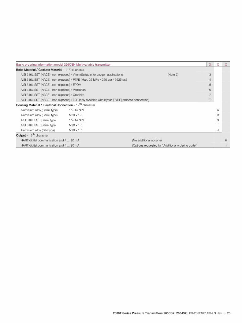
Basic ordering information model 266CSH Multivariable transmitter X X X
Bolts Material / Gaskets Material – 11th character
AISI 316L SST (NACE - non exposed) / Viton (Suitable for oxygen applications) (Note 2) 3
AISI 316L SST (NACE - non exposed) / PTFE (Max. 25 MPa / 250 bar / 3625 psi) 4
AISI 316L SST (NACE - non exposed) / EPDM 5
AISI 316L SST (NACE - non exposed) / Perbunan 6
AISI 316L SST (NACE - non exposed) / Graphite 7
AISI 316L SST (NACE - non exposed) / FEP (only available with Kynar [PVDF] process connection) T
Housing Material / Electrical Connection – 12th character
Aluminium alloy (Barrel type) 1/2-14 NPT A
Aluminium alloy (Barrel type) M20 x 1.5 B
AISI 316L SST (Barrel type) 1/2-14 NPT S
AISI 316L SST (Barrel type) M20 x 1.5 T
Aluminium alloy (DIN type) M20 x 1.5 J
Output – 13th character
HART digital communication and 4 ... 20 mA (No additional options) H
HART digital communication and 4 ... 20 mA (Options requested by "Additional ordering code") 1
Model 266CSH/CST Multivariable Model 266JSH/JST Multivariable
26 DS/266CSX/JSX-EN Rev. B | 2600T Series Pressure Transmitters 266CSX, 266JSX
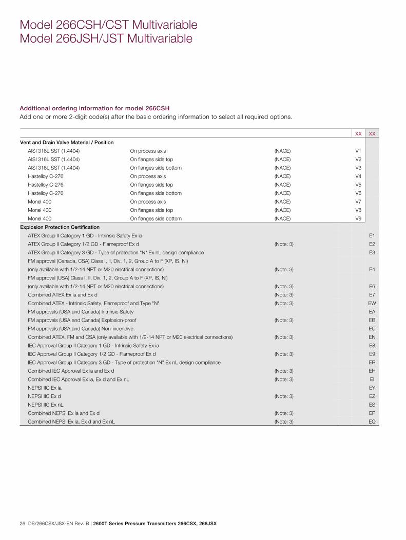
Additional ordering information for model 266CSH Add one or more 2-digit code(s) after the basic ordering information to select all required options. XX XX
Vent and Drain Valve Material / Position
AISI 316L SST (1.4404) On process axis (NACE) V1
AISI 316L SST (1.4404) On flanges side top (NACE) V2
AISI 316L SST (1.4404) On flanges side bottom (NACE) V3
Hastelloy C-276 On process axis (NACE) V4
Hastelloy C-276 On flanges side top (NACE) V5
Hastelloy C-276 On flanges side bottom (NACE) V6
Monel 400 On process axis (NACE) V7
Monel 400 On flanges side top (NACE) V8
Monel 400 On flanges side bottom (NACE) V9
Explosion Protection Certification
ATEX Group II Category 1 GD - Intrinsic Safety Ex ia E1
ATEX Group II Category 1/2 GD - Flameproof Ex d (Note: 3) E2
ATEX Group II Category 3 GD - Type of protection "N" Ex nL design compliance E3
FM approval (Canada, CSA) Class I, II, Div. 1, 2, Group A to F (XP, IS, NI)
(only available with 1/2-14 NPT or M20 electrical connections) (Note: 3)
E4
FM approval (USA) Class I, II, Div. 1, 2, Group A to F (XP, IS, Nl)
(only available with 1/2-14 NPT or M20 electrical connections) (Note: 3)
E6
Combined ATEX Ex ia and Ex d (Note: 3) E7
Combined ATEX - Intrinsic Safety, Flameproof and Type "N" (Note: 3) EW
FM approvals (USA and Canada) Intrinsic Safety EA
FM approvals (USA and Canada) Explosion-proof (Note: 3) EB
FM approvals (USA and Canada) Non-incendive EC
Combined ATEX, FM and CSA (only available with 1/2-14 NPT or M20 electrical connections) (Note: 3) EN
IEC Approval Group II Category 1 GD - Intrinsic Safety Ex ia E8
IEC Approval Group II Category 1/2 GD - Flameproof Ex d (Note: 3) E9
IEC Approval Group II Category 3 GD - Type of protection "N" Ex nL design compliance ER
Combined IEC Approval Ex ia and Ex d (Note: 3) EH
Combined IEC Approval Ex ia, Ex d and Ex nL (Note: 3) EI
NEPSI IIC Ex ia EY
NEPSI IIC Ex d (Note: 3) EZ
NEPSI IIC Ex nL ES
Combined NEPSI Ex ia and Ex d (Note: 3) EP
Combined NEPSI Ex ia, Ex d and Ex nL (Note: 3) EQ
2600T Series Pressure Transmitters 266CSX, 266JSX | DS/266CSX/JSX-EN Rev. B 27
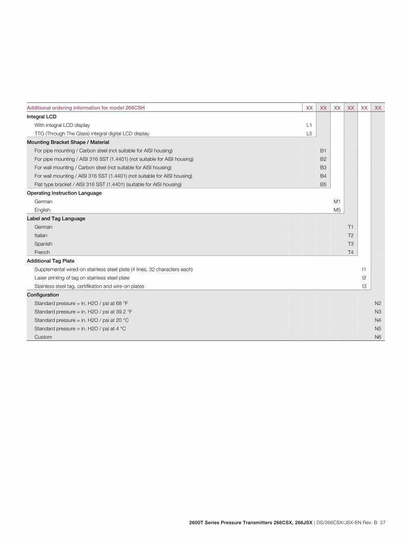
Additional ordering information for model 266CSH XX XX XX XX XX XX
Integral LCD
With integral LCD display L1
TTG (Through The Glass) integral digital LCD display L5
Mounting Bracket Shape / Material
For pipe mounting / Carbon steel (not suitable for AISI housing) B1
For pipe mounting / AISI 316 SST (1.4401) (not suitable for AISI housing) B2
For wall mounting / Carbon steel (not suitable for AISI housing) B3
For wall mounting / AISI 316 SST (1.4401) (not suitable for AISI housing) B4
Flat type bracket / AISI 316 SST (1.4401) (suitable for AISI housing) B5
Operating Instruction Language
German M1
English M5
Label and Tag Language
German T1
Italian T2
Spanish T3
French T4
Additional Tag Plate
Supplemental wired-on stainless steel plate (4 lines, 32 characters each) I1
Laser printing of tag on stainless steel plate I2
Stainless steel tag, certifikation and wire-on plates I3
Configuration
Standard pressure = in. H2O / psi at 68 °F N2
Standard pressure = in. H2O / psi at 39.2 °F N3
Standard pressure = in. H2O / psi at 20 °C N4
Standard pressure = in. H2O / psi at 4 °C N5
Custom N6
Model 266CSH/CST Multivariable Model 266JSH/JST Multivariable
28 DS/266CSX/JSX-EN Rev. B | 2600T Series Pressure Transmitters 266CSX, 266JSX
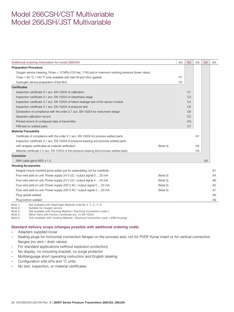
Additional ordering information for model 266CSH XX XX XX XX XX
Preparation Procedure
Oxygen service cleaning, Pmax = 12 MPa (120 bar, 1740 psi) or maximum working pressure (lower value),
Tmax = 60 °C / 140 °F (only available with inert fill and Viton gasket) P1
Hydrogen service preparation (Fluid film) P2
Certificates
Inspection certificate 3.1 acc. EN 10204 of calibration C1
Inspection certificate 3.1 acc. EN 10204 of cleanliness stage C3
Inspection certificate 3.1 acc. EN 10204 of helium leakage test of the sensor module C4
Inspection certificate 3.1 acc. EN 10204 of pressure test C5
Declaration of compliance with the order 2.1 acc. EN 10204 for instrument design C6
Separate calibration record CC
Printed record of configured data of transmitter CG
PMI test on wetted parts CT
Material Traceability
Certificate of compliance with the order 2.1 acc. EN 10204 for process wetted parts H1
Inspection certificate 3.1 acc. EN 10204 of pressure-bearing and process wetted parts
with analysis certificates as material verification (Note 4)
H3
Material certificate 2.2 acc. EN 10204 of the pressure bearing and process wetted parts H4
Connector
With cable gland M20 x 1.5 U8
Housing Accessories
Integral mount manifold (price adder just for assembling, not for manifold) A1
Four-wire add-on unit: Power supply 24 V UC / output signal 0 ... 20 mA (Note 5) A4
Four-wire add-on unit: Power supply 24 V UC / output signal 4 ... 20 mA (Note 5) A6
Four-wire add-on unit: Power supply 230 V AC / output signal 0 ... 20 mA (Note 5) A5
Four-wire add-on unit: Power supply 230 V AC / output signal 4 ... 20 mA (Note 5) A7
Plug upside welded A8
Plug bottom welded A9
Note 1: Not available with Diaphragm Material code M, V, T, C, Y, D Note 2: Suitable for Oxygen service Note 3: Not available with Housing Material / Electrical Connection code J Note 4: Minor Parts with Factory Certificate acc. to EN 10204 Note 5: Only available with Housing Material / Electrical Connection code J (DIN housing)
Standard delivery scope (changes possible with additional ordering code) – Adapters supplied loose – Sealing plugs for horizontal connection flanges on the process axis; not for PVDF Kynar insert or for vertical connection
flanges (no vent / drain valves) – For standard applications (without explosion protection) – No display, no mounting bracket, no surge protector – Multilanguage short operating instruction and English labeling – Configuration with kPa and °C units – No test, inspection, or material certificates
2600T Series Pressure Transmitters 266CSX, 266JSX | DS/266CSX/JSX-EN Rev. B 29
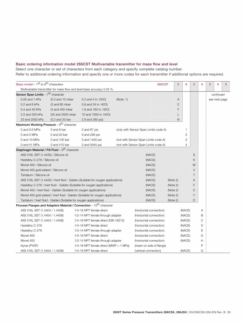
Basic ordering information model 266CST Multivariable transmitter for mass flow and level Select one character or set of characters from each category and specify complete catalog number. Refer to additional ordering information and specify one or more codes for each transmitter if additional options are required. Base model – 1st to 6th characters
Multivariable transmitter for mass flow and level base accuracy 0.04 %
266CST X X X X X X X
Sensor Span Limits – 7th character continued
0.05 and 1 kPa (0.5 and 10 mbar 0.2 and 4 in. H2O) (Note: 1) A see next page
0.2 and 6 kPa (2 and 60 mbar 0.8 and 24 in. H2O) C
0.4 and 40 kPa (4 and 400 mbar 1.6 and 160 in. H2O) F
2.5 and 250 kPa (25 and 2500 mbar 10 and 1000 in. H2O) L
20 and 2000 kPa (0.2 and 20 bar 2.9 and 290 psi) N
Maximum Working Pressure – 8th character
0 and 0.6 MPa 0 and 6 bar 0 and 87 psi (only with Sensor Span Limits code A) 1
0 and 2 MPa 0 and 20 bar 0 and 290 psi 2
0 and 10 MPa 0 and 100 bar 0 and 1450 psi (not with Sensor Span Limits code A) 3
0 and 41 MPa 0 and 410 bar 0 and 5945 psi (not with Sensor Span Limits code A) 4
Diaphragm Material / Fill Fluid – 9th character
AISI 316L SST (1.4435) / Silicone oil (NACE) S
Hastelloy C-276 / Silicone oil (NACE) K
Monel 400 / Silicone oil (NACE) M
Monel 400 gold-plated / Silicone oil (NACE) V
Tantalum / Silicone oil (NACE) T
AISI 316L SST (1.4435) / Inert fluid - Galden (Suitable for oxygen applications) (NACE) (Note 2) A
Hastelloy C-276 / Inert fluid - Galden (Suitable for oxygen applications) (NACE) (Note 2) F
Monel 400 / Inert fluid - Galden (Suitable for oxygen applications) (NACE) (Note 2) C
Monel 400 gold-plated / Inert fluid - Galden (Suitable for oxygen applications) (NACE) (Note 2) Y
Tantalum / Inert fluid - Galden (Suitable for oxygen applications) (NACE) (Note 2) D
Process Flanges and Adapters Material / Connection – 10th character
AISI 316L SST (1.4404 / 1.4408) 1/4-18 NPT female direct (horizontal connection) (NACE) A
AISI 316L SST (1.4404 / 1.4408) 1/2-14 NPT female through adapter (horizontal connection) (NACE) B
AISI 316L SST (1.4404 / 1.4408) 1/4-18 NPT female direct (DIN 19213) (horizontal connection) (NACE) C
Hastelloy C-276 1/4-18 NPT female direct (horizontal connection) (NACE) D
Hastelloy C-276 1/2-14 NPT female through adapter (horizontal connection) (NACE) E
Monel 400 1/4-18 NPT female direct (horizontal connection) (NACE) G
Monel 400 1/2-14 NPT female through adapter (horizontal connection) (NACE) H
Kynar (PVDF) 1/4-18 NPT female direct (MWP = 1 MPa) (insert on side of flange) P
AISI 316L SST (1.4404 / 1.4408) 1/4-18 NPT female direct (vertical connection) (NACE) Q

Model 266CSH/CST Multivariable Model 266JSH/JST Multivariable
30 DS/266CSX/JSX-EN Rev. B | 2600T Series Pressure Transmitters 266CSX, 266JSX
Basic ordering information model 266CST Multivariable transmitter X X X
Bolts Material / Gaskets Material – 11th character
AISI 316L SST (NACE - non exposed) / Viton (Suitable for oxygen applications) (Note 2) 3
AISI 316L SST (NACE - non exposed) / PTFE (Max. 25 MPa / 250 bar / 3625 psi) 4
AISI 316L SST (NACE - non exposed) / EPDM 5
AISI 316L SST (NACE - non exposed) / Perbunan 6
AISI 316L SST (NACE - non exposed) / Graphite 7
AISI 316L SST (NACE - non exposed) / FEP (only available with Kynar [PVDF] process connection) T
Housing Material / Electrical Connection – 12th character
Aluminium alloy (Barrel type) 1/2-14 NPT A
Aluminium alloy (Barrel type) M20 x 1.5 B
AISI 316L SST (Barrel type) 1/2-14 NPT S
AISI 316L SST (Barrel type) M20 x 1.5 T
Aluminium alloy (DIN type) M20 x 1.5 J
Output – 13th character
HART digital communication and 4 ... 20 mA (No additional options) H
HART digital communication and 4 ... 20 mA (Options requested by "Additional ordering code") 1
2600T Series Pressure Transmitters 266CSX, 266JSX | DS/266CSX/JSX-EN Rev. B 31
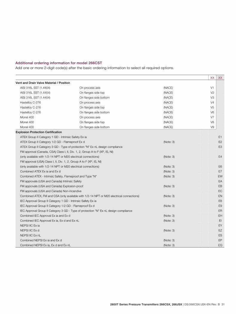
Additional ordering information for model 266CST Add one or more 2-digit code(s) after the basic ordering information to select all required options.
XX XX
Vent and Drain Valve Material / Position
AISI 316L SST (1.4404) On process axis (NACE) V1
AISI 316L SST (1.4404) On flanges side top (NACE) V2
AISI 316L SST (1.4404) On flanges side bottom (NACE) V3
Hastelloy C-276 On process axis (NACE) V4
Hastelloy C-276 On flanges side top (NACE) V5
Hastelloy C-276 On flanges side bottom (NACE) V6
Monel 400 On process axis (NACE) V7
Monel 400 On flanges side top (NACE) V8
Monel 400 On flanges side bottom (NACE) V9
Explosion Protection Certification
ATEX Group II Category 1 GD - Intrinsic Safety Ex ia E1
ATEX Group II Category 1/2 GD - Flameproof Ex d (Note: 3) E2
ATEX Group II Category 3 GD - Type of protection "N" Ex nL design compliance E3
FM approval (Canada, CSA) Class I, II, Div. 1, 2, Group A to F (XP, IS, NI)
(only available with 1/2-14 NPT or M20 electrical connections) (Note: 3)
E4
FM approval (USA) Class I, II, Div. 1, 2, Group A to F (XP, IS, Nl)
(only available with 1/2-14 NPT or M20 electrical connections) (Note: 3)
E6
Combined ATEX Ex ia and Ex d (Note: 3) E7
Combined ATEX - Intrinsic Safety, Flameproof and Type "N" (Note: 3) EW
FM approvals (USA and Canada) Intrinsic Safety EA
FM approvals (USA and Canada) Explosion-proof (Note: 3) EB
FM approvals (USA and Canada) Non-incendive EC
Combined ATEX, FM and CSA (only available with 1/2-14 NPT or M20 electrical connections) (Note: 3) EN
IEC Approval Group II Category 1 GD - Intrinsic Safety Ex ia E8
IEC Approval Group II Category 1/2 GD - Flameproof Ex d (Note: 3) E9
IEC Approval Group II Category 3 GD - Type of protection "N" Ex nL design compliance ER
Combined IEC Approval Ex ia and Ex d (Note: 3) EH
Combined IEC Approval Ex ia, Ex d and Ex nL (Note: 3) EI
NEPSI IIC Ex ia EY
NEPSI IIC Ex d (Note: 3) EZ
NEPSI IIC Ex nL ES
Combined NEPSI Ex ia and Ex d (Note: 3) EP
Combined NEPSI Ex ia, Ex d and Ex nL (Note: 3) EQ

Model 266CSH/CST Multivariable Model 266JSH/JST Multivariable
32 DS/266CSX/JSX-EN Rev. B | 2600T Series Pressure Transmitters 266CSX, 266JSX
Additional ordering information for model 266CST XX XX XX XX XX XX
Integral LCD
With integral LCD display L1
TTG (Through The Glass) integral digital LCD display L5
Mounting Bracket Shape / Material
For pipe mounting / Carbon steel (not suitable for AISI housing) B1
For pipe mounting / AISI 316 SST (1.4401) (not suitable for AISI housing) B2
For wall mounting / Carbon steel (not suitable for AISI housing) B3
For wall mounting / AISI 316 SST (1.4401) (not suitable for AISI housing) B4
Flat type bracket / AISI 316 SST (1.4401) (suitable for AISI housing) B5
Operating Instruction Language
German M1
English M5
Label and Tag Language
German T1
Italian T2
Spanish T3
French T4
Additional Tag Plate
Supplemental wired-on stainless steel plate (4 lines, 30 characters each) I1
Laser printing of tag on stainless steel plate I2
Stainless steel tag, certifikation and wire-on plates I3
Configuration
Standard pressure = in. H2O / psi at 68 °F N2
Standard pressure = in. H2O / psi at 39.2 °F N3
Standard pressure = in. H2O / psi at 20 °C N4
Standard pressure = in. H2O / psi at 4 °C N5
Custom N6
2600T Series Pressure Transmitters 266CSX, 266JSX | DS/266CSX/JSX-EN Rev. B 33
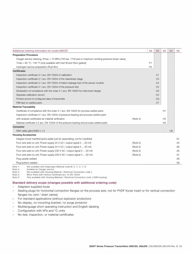
Additional ordering information for model 266CST XX XX XX XX XX
Preparation Procedure
Oxygen service cleaning, Pmax = 12 MPa (120 bar, 1740 psi) or maximum working pressure (lower value),
Tmax = 60 °C / 140 °F (only available with inert fill and Viton gasket) P1
Hydrogen service preparation (Fluid film) P2
Certificates
Inspection certificate 3.1 acc. EN 10204 of calibration C1
Inspection certificate 3.1 acc. EN 10204 of the cleanliness stage C3
Inspection certificate 3.1 acc. EN 10204 of helium leakage test of the sensor module C4
Inspection certificate 3.1 acc. EN 10204 of the pressure test C5
Declaration of compliance with the order 2.1 acc. EN 10204 for instrument design C6
Separate calibration record CC
Printed record of configured data of transmitter CG
PMI test on wetted parts CT
Material Traceability
Certificate of compliance with the order 2.1 acc. EN 10204 for process wetted parts H1
Inspection certificate 3.1 acc. EN 10204 of pressure-bearing and process wetted parts
with analysis certificates as material verification (Note 4)
H3
Material certificate 2.2 acc. EN 10204 of the pressure bearing and process wetted parts H4
Connector
With cable gland M20 x 1.5 U8
Housing Accessories
Integral mount manifold (price adder just for assembling, not for manifold) A1
Four-wire add-on unit: Power supply 24 V UC / output signal 0 ... 20 mA (Note 5) A4
Four-wire add-on unit: Power supply 24 V UC / output signal 4 ... 20 mA (Note 5) A6
Four-wire add-on unit: Power supply 230 V AC / output signal 0 ... 20 mA (Note 5) A5
Four-wire add-on unit: Power supply 230 V AC / output signal 4 ... 20 mA (Note 5) A7
Plug upside welded A8
Plug bottom welded A9
Note 1: Not available with Diaphragm Material code M, V, T, C, Y, D Note 2: Suitable for Oxygen service Note 3: Not available with Housing Material / Electrical Connection code J Note 4: Minor Parts with Factory Certificate acc. to EN 10204 Note 5: Only available with Housing Material / Electrical Connection code J (DIN housing)
Standard delivery scope (changes possible with additional ordering code) – Adapters supplied loose – Sealing plugs for horizontal connection flanges on the process axis; not for PVDF Kynar insert or for vertical connection
flanges (no vent / drain valves) – For standard applications (without explosion protection) – No display, no mounting bracket, no surge protector – Multilanguage short operating instruction and English labeling – Configuration with kPa and °C units – No test, inspection, or material certificates
Model 266CSH/CST Multivariable Model 266JSH/JST Multivariable
34 DS/266CSX/JSX-EN Rev. B | 2600T Series Pressure Transmitters 266CSX, 266JSX
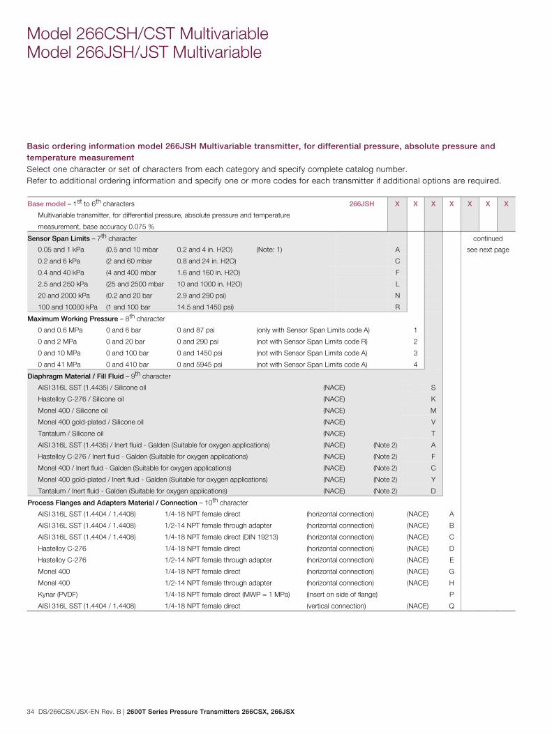
Basic ordering information model 266JSH Multivariable transmitter, for differential pressure, absolute pressure and temperature measurement Select one character or set of characters from each category and specify complete catalog number. Refer to additional ordering information and specify one or more codes for each transmitter if additional options are required. Base model – 1st to 6th characters
Multivariable transmitter, for differential pressure, absolute pressure and temperature
measurement, base accuracy 0.075 %
266JSH X X X X X X X
Sensor Span Limits – 7th character continued
0.05 and 1 kPa (0.5 and 10 mbar 0.2 and 4 in. H2O) (Note: 1) A see next page
0.2 and 6 kPa (2 and 60 mbar 0.8 and 24 in. H2O) C
0.4 and 40 kPa (4 and 400 mbar 1.6 and 160 in. H2O) F
2.5 and 250 kPa (25 and 2500 mbar 10 and 1000 in. H2O) L
20 and 2000 kPa (0.2 and 20 bar 2.9 and 290 psi) N
100 and 10000 kPa (1 and 100 bar 14.5 and 1450 psi) R
Maximum Working Pressure – 8th character
0 and 0.6 MPa 0 and 6 bar 0 and 87 psi (only with Sensor Span Limits code A) 1
0 and 2 MPa 0 and 20 bar 0 and 290 psi (not with Sensor Span Limits code R) 2
0 and 10 MPa 0 and 100 bar 0 and 1450 psi (not with Sensor Span Limits code A) 3
0 and 41 MPa 0 and 410 bar 0 and 5945 psi (not with Sensor Span Limits code A) 4
Diaphragm Material / Fill Fluid – 9th character
AISI 316L SST (1.4435) / Silicone oil (NACE) S
Hastelloy C-276 / Silicone oil (NACE) K
Monel 400 / Silicone oil (NACE) M
Monel 400 gold-plated / Silicone oil (NACE) V
Tantalum / Silicone oil (NACE) T
AISI 316L SST (1.4435) / Inert fluid - Galden (Suitable for oxygen applications) (NACE) (Note 2) A
Hastelloy C-276 / Inert fluid - Galden (Suitable for oxygen applications) (NACE) (Note 2) F
Monel 400 / Inert fluid - Galden (Suitable for oxygen applications) (NACE) (Note 2) C
Monel 400 gold-plated / Inert fluid - Galden (Suitable for oxygen applications) (NACE) (Note 2) Y
Tantalum / Inert fluid - Galden (Suitable for oxygen applications) (NACE) (Note 2) D
Process Flanges and Adapters Material / Connection – 10th character
AISI 316L SST (1.4404 / 1.4408) 1/4-18 NPT female direct (horizontal connection) (NACE) A
AISI 316L SST (1.4404 / 1.4408) 1/2-14 NPT female through adapter (horizontal connection) (NACE) B
AISI 316L SST (1.4404 / 1.4408) 1/4-18 NPT female direct (DIN 19213) (horizontal connection) (NACE) C
Hastelloy C-276 1/4-18 NPT female direct (horizontal connection) (NACE) D
Hastelloy C-276 1/2-14 NPT female through adapter (horizontal connection) (NACE) E
Monel 400 1/4-18 NPT female direct (horizontal connection) (NACE) G
Monel 400 1/2-14 NPT female through adapter (horizontal connection) (NACE) H
Kynar (PVDF) 1/4-18 NPT female direct (MWP = 1 MPa) (insert on side of flange) P
AISI 316L SST (1.4404 / 1.4408) 1/4-18 NPT female direct (vertical connection) (NACE) Q

2600T Series Pressure Transmitters 266CSX, 266JSX | DS/266CSX/JSX-EN Rev. B 35
Basic ordering information model 266JSH Multivariable transmitter X X X
Bolts Material / Gaskets Material – 11th character
AISI 316L SST (NACE - non exposed) / Viton (Suitable for oxygen applications) (Note 2) 3
AISI 316L SST (NACE - non exposed) / PTFE (Max. 25 MPa / 250 bar / 3625 psi) 4
AISI 316L SST (NACE - non exposed) / EPDM 5
AISI 316L SST (NACE - non exposed) / Perbunan 6
AISI 316L SST (NACE - non exposed) / Graphite 7
AISI 316L SST (NACE - non exposed) / FEP (only available with Kynar [PVDF] process connection) T
Housing Material / Electrical Connection – 12th character
Aluminium alloy (Barrel type) 1/2-14 NPT A
Aluminium alloy (Barrel type) M20 x 1.5 B
AISI 316L SST (Barrel type) 1/2-14 NPT S
AISI 316L SST (Barrel type) M20 x 1.5 T
Aluminium alloy (DIN type) M20 x 1.5 J
Output – 13th character
HART digital communication and 4 ... 20 mA (No additional options) H
HART digital communication and 4 ... 20 mA (Options requested by "Additional ordering code") 1

Model 266CSH/CST Multivariable Model 266JSH/JST Multivariable
36 DS/266CSX/JSX-EN Rev. B | 2600T Series Pressure Transmitters 266CSX, 266JSX
Additional ordering information for model 266JSH Add one or more 2-digit code(s) after the basic ordering information to select all required options.
XX XX
Vent and Drain Valve Material / Position
AISI 316L SST (1.4404) On process axis (NACE) V1
AISI 316L SST (1.4404) On flanges side top (NACE) V2
AISI 316L SST (1.4404) On flanges side bottom (NACE) V3
Hastelloy C-276 On process axis (NACE) V4
Hastelloy C-276 On flanges side top (NACE) V5
Hastelloy C-276 On flanges side bottom (NACE) V6
Monel 400 On process axis (NACE) V7
Monel 400 On flanges side top (NACE) V8
Monel 400 On flanges side bottom (NACE) V9
Explosion Protection Certification
ATEX Group II Category 1 GD - Intrinsic Safety Ex ia E1
ATEX Group II Category 1/2 GD - Flameproof Ex d (Note: 3) E2
ATEX Group II Category 3 GD - Type of protection "N" Ex nL design compliance E3
FM approval (Canada, CSA) Class I, II, Div. 1, 2, Group A to F (XP, IS, NI)
(only available with 1/2-14 NPT or M20 electrical connections) (Note: 3)
E4
FM approval (USA) Class I, II, Div. 1, 2, Group A to F (XP, IS, Nl)
(only available with 1/2-14 NPT or M20 electrical connections) (Note: 3)
E6
Combined ATEX Ex ia and Ex d (Note: 3) E7
Combined ATEX - Intrinsic Safety, Flameproof and Type "N" (Note: 3) EW
FM approvals (USA and Canada) Intrinsic Safety EA
FM approvals (USA and Canada) Explosion-proof (Note: 3) EB
FM approvals (USA and Canada) Non-incendive EC
Combined ATEX, FM and CSA (only available with 1/2-14 NPT or M20 electrical connections) (Note: 3) EN
IEC Approval Group II Category 1 GD - Intrinsic Safety Ex ia E8
IEC Approval Group II Category 1/2 GD - Flameproof Ex d (Note: 3) E9
IEC Approval Group II Category 3 GD - Type of protection "N" Ex nL design compliance ER
Combined IEC Approval Ex ia and Ex d (Note: 3) EH
Combined IEC Approval Ex ia, Ex d and Ex nL (Note: 3) EI
NEPSI IIC Ex ia EY
NEPSI IIC Ex d (Note: 3) EZ
NEPSI IIC Ex nL ES
Combined NEPSI Ex ia and Ex d (Note: 3) EP
Combined NEPSI Ex ia, Ex d and Ex nL (Note: 3) EQ
2600T Series Pressure Transmitters 266CSX, 266JSX | DS/266CSX/JSX-EN Rev. B 37
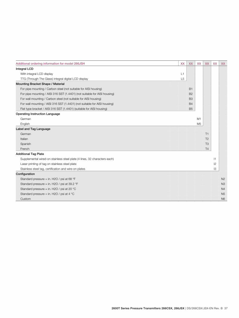
Additional ordering information for model 266JSH XX XX XX XX XX XX
Integral LCD
With integral LCD display L1
TTG (Through The Glass) integral digital LCD display L5
Mounting Bracket Shape / Material
For pipe mounting / Carbon steel (not suitable for AISI housing) B1
For pipe mounting / AISI 316 SST (1.4401) (not suitable for AISI housing) B2
For wall mounting / Carbon steel (not suitable for AISI housing) B3
For wall mounting / AISI 316 SST (1.4401) (not suitable for AISI housing) B4
Flat type bracket / AISI 316 SST (1.4401) (suitable for AISI housing) B5
Operating Instruction Language
German M1
English M5
Label and Tag Language
German T1
Italian T2
Spanish T3
French T4
Additional Tag Plate
Supplemental wired-on stainless steel plate (4 lines, 32 characters each) I1
Laser printing of tag on stainless steel plate I2
Stainless steel tag, certification and wire-on plates I3
Configuration
Standard pressure = in. H2O / psi at 68 °F N2
Standard pressure = in. H2O / psi at 39.2 °F N3
Standard pressure = in. H2O / psi at 20 °C N4
Standard pressure = in. H2O / psi at 4 °C N5
Custom N6

Model 266CSH/CST Multivariable Model 266JSH/JST Multivariable
38 DS/266CSX/JSX-EN Rev. B | 2600T Series Pressure Transmitters 266CSX, 266JSX
Additional ordering information for model 266JSH XX XX XX XX XX
Preparation Procedure
Oxygen service cleaning, Pmax = 12 MPa (120 bar, 1740 psi) or maximum working pressure (lower value),
Tmax = 60 °C / 140 °F (only available with inert fill and Viton gasket) P1
Hydrogen service preparation (Fluid film) P2
Certificates
Inspection certificate 3.1 acc. EN 10204 of calibration C1
Inspection certificate 3.1 acc. EN 10204 of cleanliness stage C3
Inspection certificate 3.1 acc. EN 10204 of helium leakage test of the sensor module C4
Inspection certificate 3.1 acc. EN 10204 of pressure test C5
Declaration of compliance with the order 2.1 acc. EN 10204 for instrument design C6
Separate calibration record CC
Printed record of configured data of transmitter CG
PMI test on wetted parts CT
Material Traceability
Certificate of compliance with the order 2.1 acc. EN 10204 for process wetted parts H1
Inspection certificate 3.1 acc. EN 10204 of pressure-bearing and process wetted parts
with analysis certificates as material verification (Note 4)
H3
Material certificate 2.2 acc. EN 10204 of the pressure bearing and process wetted parts H4
Connector
With cable gland M20 x 1.5 U8
Housing Accessories
Integral mount manifold (price adder just for assembling, not for manifold) A1
Four-wire add-on unit: Power supply 24 V UC / output signal 0 ... 20 mA (Note 5) A4
Four-wire add-on unit: Power supply 24 V UC / output signal 4 ... 20 mA (Note 5) A6
Four-wire add-on unit: Power supply 230 V AC / output signal 0 ... 20 mA (Note 5) A5
Four-wire add-on unit: Power supply 230 V AC / output signal 4 ... 20 mA (Note 5) A7
Plug upside welded A8
Plug bottom welded A9
Note 1: Not available with Diaphragm Material code M, V, T, C, Y, D Note 2: Suitable for Oxygen service Note 3: Not available with Housing Material / Electrical Connection code J Note 4: Minor Parts with Factory Certificate acc. to EN 10204 Note 5: Only available with Housing Material / Electrical Connection code J (DIN housing)
Standard delivery scope (changes possible with additional ordering code) – Adapters supplied loose – Sealing plugs for horizontal connection flanges on the process axis; not for PVDF Kynar insert or for vertical connection
flanges (no vent / drain valves) – For standard applications (without explosion protection) – No display, no mounting bracket, no surge protector – Multilanguage short operating instruction and English labeling – Configuration with kPa and °C units – No test, inspection, or material certificates
2600T Series Pressure Transmitters 266CSX, 266JSX | DS/266CSX/JSX-EN Rev. B 39
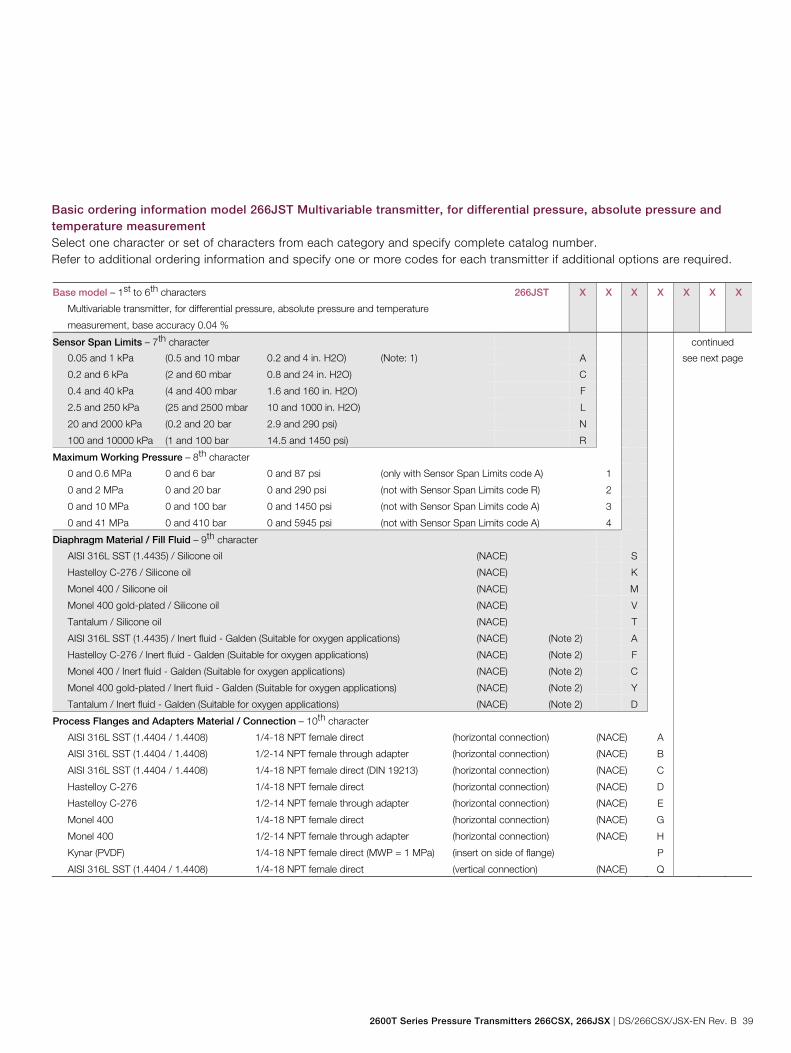
Basic ordering information model 266JST Multivariable transmitter, for differential pressure, absolute pressure and temperature measurement Select one character or set of characters from each category and specify complete catalog number. Refer to additional ordering information and specify one or more codes for each transmitter if additional options are required. Base model – 1st to 6th characters
Multivariable transmitter, for differential pressure, absolute pressure and temperature
measurement, base accuracy 0.04 %
266JST X X X X X X X
Sensor Span Limits – 7th character continued
0.05 and 1 kPa (0.5 and 10 mbar 0.2 and 4 in. H2O) (Note: 1) A see next page
0.2 and 6 kPa (2 and 60 mbar 0.8 and 24 in. H2O) C
0.4 and 40 kPa (4 and 400 mbar 1.6 and 160 in. H2O) F
2.5 and 250 kPa (25 and 2500 mbar 10 and 1000 in. H2O) L
20 and 2000 kPa (0.2 and 20 bar 2.9 and 290 psi) N
100 and 10000 kPa (1 and 100 bar 14.5 and 1450 psi) R
Maximum Working Pressure – 8th character
0 and 0.6 MPa 0 and 6 bar 0 and 87 psi (only with Sensor Span Limits code A) 1
0 and 2 MPa 0 and 20 bar 0 and 290 psi (not with Sensor Span Limits code R) 2
0 and 10 MPa 0 and 100 bar 0 and 1450 psi (not with Sensor Span Limits code A) 3
0 and 41 MPa 0 and 410 bar 0 and 5945 psi (not with Sensor Span Limits code A) 4
Diaphragm Material / Fill Fluid – 9th character
AISI 316L SST (1.4435) / Silicone oil (NACE) S
Hastelloy C-276 / Silicone oil (NACE) K
Monel 400 / Silicone oil (NACE) M
Monel 400 gold-plated / Silicone oil (NACE) V
Tantalum / Silicone oil (NACE) T
AISI 316L SST (1.4435) / Inert fluid - Galden (Suitable for oxygen applications) (NACE) (Note 2) A
Hastelloy C-276 / Inert fluid - Galden (Suitable for oxygen applications) (NACE) (Note 2) F
Monel 400 / Inert fluid - Galden (Suitable for oxygen applications) (NACE) (Note 2) C
Monel 400 gold-plated / Inert fluid - Galden (Suitable for oxygen applications) (NACE) (Note 2) Y
Tantalum / Inert fluid - Galden (Suitable for oxygen applications) (NACE) (Note 2) D
Process Flanges and Adapters Material / Connection – 10th character
AISI 316L SST (1.4404 / 1.4408) 1/4-18 NPT female direct (horizontal connection) (NACE) A
AISI 316L SST (1.4404 / 1.4408) 1/2-14 NPT female through adapter (horizontal connection) (NACE) B
AISI 316L SST (1.4404 / 1.4408) 1/4-18 NPT female direct (DIN 19213) (horizontal connection) (NACE) C
Hastelloy C-276 1/4-18 NPT female direct (horizontal connection) (NACE) D
Hastelloy C-276 1/2-14 NPT female through adapter (horizontal connection) (NACE) E
Monel 400 1/4-18 NPT female direct (horizontal connection) (NACE) G
Monel 400 1/2-14 NPT female through adapter (horizontal connection) (NACE) H
Kynar (PVDF) 1/4-18 NPT female direct (MWP = 1 MPa) (insert on side of flange) P
AISI 316L SST (1.4404 / 1.4408) 1/4-18 NPT female direct (vertical connection) (NACE) Q
Model 266CSH/CST Multivariable Model 266JSH/JST Multivariable
40 DS/266CSX/JSX-EN Rev. B | 2600T Series Pressure Transmitters 266CSX, 266JSX
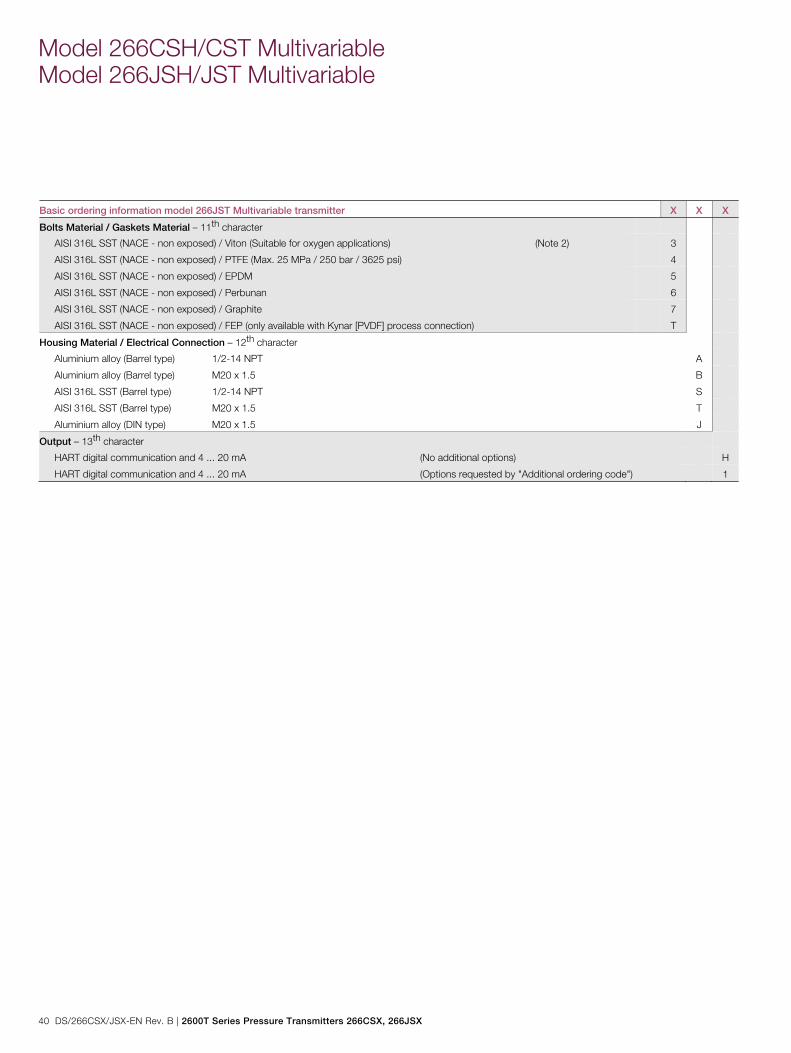
Basic ordering information model 266JST Multivariable transmitter X X X
Bolts Material / Gaskets Material – 11th character
AISI 316L SST (NACE - non exposed) / Viton (Suitable for oxygen applications) (Note 2) 3
AISI 316L SST (NACE - non exposed) / PTFE (Max. 25 MPa / 250 bar / 3625 psi) 4
AISI 316L SST (NACE - non exposed) / EPDM 5
AISI 316L SST (NACE - non exposed) / Perbunan 6
AISI 316L SST (NACE - non exposed) / Graphite 7
AISI 316L SST (NACE - non exposed) / FEP (only available with Kynar [PVDF] process connection) T
Housing Material / Electrical Connection – 12th character
Aluminium alloy (Barrel type) 1/2-14 NPT A
Aluminium alloy (Barrel type) M20 x 1.5 B
AISI 316L SST (Barrel type) 1/2-14 NPT S
AISI 316L SST (Barrel type) M20 x 1.5 T
Aluminium alloy (DIN type) M20 x 1.5 J
Output – 13th character
HART digital communication and 4 ... 20 mA (No additional options) H
HART digital communication and 4 ... 20 mA (Options requested by "Additional ordering code") 1

2600T Series Pressure Transmitters 266CSX, 266JSX | DS/266CSX/JSX-EN Rev. B 41
Additional ordering information for model 266JST Add one or more 2-digit code(s) after the basic ordering information to select all required options. XX XX
Vent and Drain Valve Material / Position
AISI 316L SST (1.4404) On process axis (NACE) V1
AISI 316L SST (1.4404) On flanges side top (NACE) V2
AISI 316L SST (1.4404) On flanges side bottom (NACE) V3
Hastelloy C-276 On process axis (NACE) V4
Hastelloy C-276 On flanges side top (NACE) V5
Hastelloy C-276 On flanges side bottom (NACE) V6
Monel 400 On process axis (NACE) V7
Monel 400 On flanges side top (NACE) V8
Monel 400 On flanges side bottom (NACE) V9
Explosion Protection Certification
ATEX Group II Category 1 GD - Intrinsic Safety Ex ia E1
ATEX Group II Category 1/2 GD - Flameproof Ex d (Note: 3) E2
ATEX Group II Category 3 GD - Type of protection "N" Ex nL design compliance E3
FM approval (Canada, CSA) Class I, II, Div. 1, 2, Group A to F (XP, IS, NI)
(only available with 1/2-14 NPT or M20 electrical connections) (Note: 3)
E4
FM approval (USA) Class I, II, Div. 1, 2, Group A to F (XP, IS, Nl)
(only available with 1/2-14 NPT or M20 electrical connections) (Note: 3)
E6
Combined ATEX Ex ia and Ex d (Note: 3) E7
Combined ATEX - Intrinsic Safety, Flameproof and Type "N" (Note: 3) EW
FM approvals (USA and Canada) Intrinsic Safety EA
FM approvals (USA and Canada) Explosion-proof (Note: 3) EB
FM approvals (USA and Canada) Non-incendive EC
Combined ATEX, FM and CSA (only available with 1/2-14 NPT or M20 electrical connections) (Note: 3) EN
IEC Approval Group II Category 1 GD - Intrinsic Safety Ex ia E8
IEC Approval Group II Category 1/2 GD - Flameproof Ex d (Note: 3) E9
IEC Approval Group II Category 3 GD - Type of protection "N" Ex nL design compliance ER
Combined IEC Approval Ex ia and Ex d (Note: 3) EH
Combined IEC Approval Ex ia, Ex d and Ex nL (Note: 3) EI
NEPSI IIC Ex ia EY
NEPSI IIC Ex d (Note: 3) EZ
NEPSI IIC Ex nL ES
Combined NEPSI Ex ia and Ex d (Note: 3) EP
Combined NEPSI Ex ia, Ex d and Ex nL (Note: 3) EQ
Model 266CSH/CST Multivariable Model 266JSH/JST Multivariable
42 DS/266CSX/JSX-EN Rev. B | 2600T Series Pressure Transmitters 266CSX, 266JSX
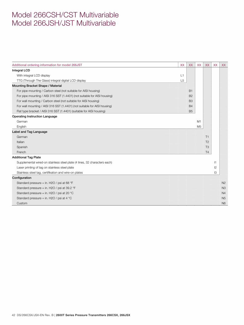
Additional ordering information for model 266JST XX XX XX XX XX XX
Integral LCD
With integral LCD display L1
TTG (Through The Glass) integral digital LCD display L5
Mounting Bracket Shape / Material
For pipe mounting / Carbon steel (not suitable for AISI housing) B1
For pipe mounting / AISI 316 SST (1.4401) (not suitable for AISI housing) B2
For wall mounting / Carbon steel (not suitable for AISI housing) B3
For wall mounting / AISI 316 SST (1.4401) (not suitable for AISI housing) B4
Flat type bracket / AISI 316 SST (1.4401) (suitable for AISI housing) B5
Operating Instruction Language
German M1
English M5
Label and Tag Language
German T1
Italian T2
Spanish T3
French T4
Additional Tag Plate
Supplemental wired-on stainless steel plate (4 lines, 32 characters each) I1
Laser printing of tag on stainless steel plate I2
Stainless steel tag, certifikation and wire-on plates I3
Configuration
Standard pressure = in. H2O / psi at 68 °F N2
Standard pressure = in. H2O / psi at 39.2 °F N3
Standard pressure = in. H2O / psi at 20 °C N4
Standard pressure = in. H2O / psi at 4 °C N5
Custom N6
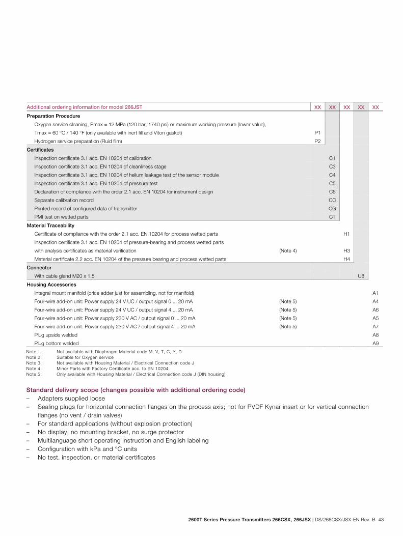
2600T Series Pressure Transmitters 266CSX, 266JSX | DS/266CSX/JSX-EN Rev. B 43
Additional ordering information for model 266JST XX XX XX XX XX
Preparation Procedure
Oxygen service cleaning, Pmax = 12 MPa (120 bar, 1740 psi) or maximum working pressure (lower value),
Tmax = 60 °C / 140 °F (only available with inert fill and Viton gasket) P1
Hydrogen service preparation (Fluid film) P2
Certificates
Inspection certificate 3.1 acc. EN 10204 of calibration C1
Inspection certificate 3.1 acc. EN 10204 of cleanliness stage C3
Inspection certificate 3.1 acc. EN 10204 of helium leakage test of the sensor module C4
Inspection certificate 3.1 acc. EN 10204 of pressure test C5
Declaration of compliance with the order 2.1 acc. EN 10204 for instrument design C6
Separate calibration record CC
Printed record of configured data of transmitter CG
PMI test on wetted parts CT
Material Traceability
Certificate of compliance with the order 2.1 acc. EN 10204 for process wetted parts H1
Inspection certificate 3.1 acc. EN 10204 of pressure-bearing and process wetted parts
with analysis certificates as material verification (Note 4)
H3
Material certificate 2.2 acc. EN 10204 of the pressure bearing and process wetted parts H4
Connector
With cable gland M20 x 1.5 U8
Housing Accessories
Integral mount manifold (price adder just for assembling, not for manifold) A1
Four-wire add-on unit: Power supply 24 V UC / output signal 0 ... 20 mA (Note 5) A4
Four-wire add-on unit: Power supply 24 V UC / output signal 4 ... 20 mA (Note 5) A6
Four-wire add-on unit: Power supply 230 V AC / output signal 0 ... 20 mA (Note 5) A5
Four-wire add-on unit: Power supply 230 V AC / output signal 4 ... 20 mA (Note 5) A7
Plug upside welded A8
Plug bottom welded A9
Note 1: Not available with Diaphragm Material code M, V, T, C, Y, D Note 2: Suitable for Oxygen service Note 3: Not available with Housing Material / Electrical Connection code J Note 4: Minor Parts with Factory Certificate acc. to EN 10204 Note 5: Only available with Housing Material / Electrical Connection code J (DIN housing)
Standard delivery scope (changes possible with additional ordering code) – Adapters supplied loose – Sealing plugs for horizontal connection flanges on the process axis; not for PVDF Kynar insert or for vertical connection
flanges (no vent / drain valves) – For standard applications (without explosion protection) – No display, no mounting bracket, no surge protector – Multilanguage short operating instruction and English labeling – Configuration with kPa and °C units – No test, inspection, or material certificates
Model 266CSH/CST Multivariable Model 266JSH/JST Multivariable
44 DS/266CSX/JSX-EN Rev. B | 2600T Series Pressure Transmitters 266CSX, 266JSX
Important remark for all models The selection of suitable wetted parts and filling fluid for compatibility with the process media is a customers responsibility, if not otherwise notified before manufacturing. NACE compliance information 1 The materials of constructions comply with metallurgical recommendations of NACE MR0175/ISO 15156 for sour oil field
production environments. As specific environmental limits may apply to certain materials, please consult latest standard for further details. Materials AISI 316 / AISI 316L, Hastelloy C-276, Monel 400 also conform to NACE MR0103 for sour refining environments.
2 NACE MR0175 addresses bolting requirements in two classes: — Exposed bolts: bolts directly exposed to the sour environment or buried, encapsulated or anyway not exposed to
atmosphere — Non exposed bolts: the bolting must not be directly exposed to sour environments, and must be directly exposed to
the atmosphere at all times. 266CSH, 266CST, 266JSH, 266JST bolting identified by “NACE” are in compliance to the requirements of NACE MR0175 when considered “non exposed bolting” Change from one to two columns
Trademarks ™ Hastelloy C-276 is a Cabot Corporation trademark
® Monel is a registered trademark of Special Metals Corporation
™ Viton is a DuPont de Nemours trademark
™ Galden is a Montefluos trademark
™ Kynar is an Elf Atochem North America Inc. trademark Change from two to one column

Notes
2600T Series Pressure Transmitters 266CSX, 266JSX | DS/266CSX/JSX-EN Rev. B 45
Notes

Notes
46 DS/266CSX/JSX-EN Rev. B | 2600T Series Pressure Transmitters 266CSX, 266JSX
Notes

Notes
2600T Series Pressure Transmitters 266CSX, 266JSX | DS/266CSX/JSX-EN Rev. B 47
Notes


HMI – Automação e Instrumentação, Lda.
Rua dos 5 Caminhos, nº 570
4780-382 Santo Tirso
PORTUGAL
Web: www.hmi.pt
Tel. +351 252 850 501
Fax. +351 300 013 487
Email: [email protected]
Our offering:
Actuators and
Positioners
Analytical Instruments
Device Management,
Fieldbus and Wireless
Flow Measurement
Force Measurement
Level Measurement
Natural Gas
Measurement
Pressure Measurement
Recorders and
Controllers
Temperature
Measurement
Contact us
DS
/266
CS
X/JS
X-EN
Rev
. B 0
2.20
17ABB Limited Industrial Automation Howard Road, St. Neots Cambridgeshire, PE19 8EU UK Tel: +44 (0)870 600 6122 Fax: +44 (0)1480 213 339 Mail: [email protected] ABB Inc. Industrial Automation 125 E. County Line Road Warminster, PA 18974 USA Tel: +1 215 674 6000 Fax: +1 215 674 7183 ABB Automation Products GmbH Industrial Automation Schillerstr. 72 32425 Minden Germany Tel: +49 571 830-0 Fax: +49 571 830-1806 ABB S.p.A. Industrial Automation Via Luigi Vaccani 4 22016 Tremezzina Como Italy Tel: +39 0344 58111 Mail: [email protected] www.abb.com/pressure
Note We reserve the right to make technical changes or modify the contents of this document without prior notice. With regard to purchase orders, the agreed particulars shall prevail. ABB does not accept any responsibility whatsoever for potential errors or possible lack of information in this document. We reserve all rights in this document and in the subject matter and illustrations contained therein. Any reproduction, disclosure to third parties or utilization of its contents – in whole or in parts – is forbidden without prior written consent of ABB. Copyright© 2017 ABB All rights reserved 3KXP400004R1001
Sales
Service