FICHA TÉCNICA DE PRODUTO PRODUCT DATASHEET - hmi.pt · HMI HMI – ––– Automação e...
31
HMI HMI HMI HMI – Automação e Instrumentação, Lda. Automação e Instrumentação, Lda. Automação e Instrumentação, Lda. Automação e Instrumentação, Lda. Rua dos 5 Caminhos, nº 570 4780-382 Santo Tirso PORTUGAL Web: www.hmi.pt Tel. +351 252 850 501 Fax. +351 300 013 487 Email: [email protected] FICHA TÉCNICA DE PRODUTO PRODUCT DATASHEET
Transcript of FICHA TÉCNICA DE PRODUTO PRODUCT DATASHEET - hmi.pt · HMI HMI – ––– Automação e...

HMI HMI HMI HMI –––– Automação e Instrumentação, Lda.Automação e Instrumentação, Lda.Automação e Instrumentação, Lda.Automação e Instrumentação, Lda.
Rua dos 5 Caminhos, nº 570 4780-382 Santo Tirso PORTUGAL Web: www.hmi.pt
Tel. +351 252 850 501 Fax. +351 300 013 487
Email: [email protected]
FICHA TÉCNICA DE PRODUTO
PRODUCT DATASHEET
Data Sheet SS/261GS/AS-EN Rev. 07
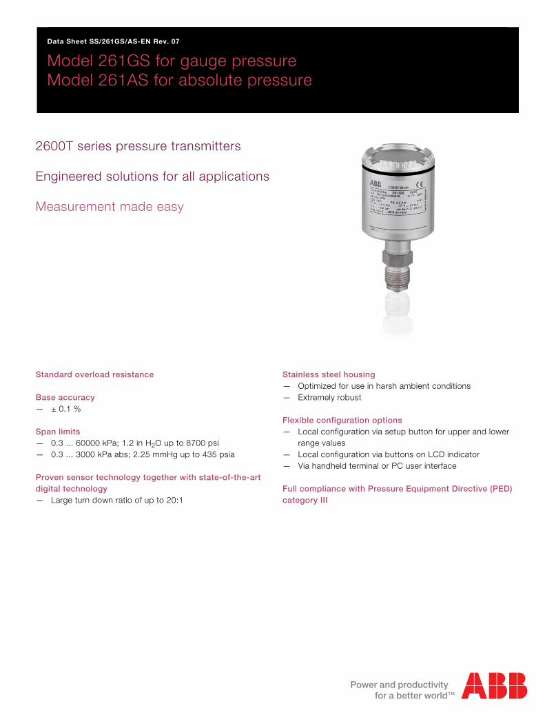
Model 261GS for gauge pressure Model 261AS for absolute pressure
2600T series pressure transmitters Engineered solutions for all applications Measurement made easy
Standard overload resistance Base accuracy — ± 0.1 % Span limits — 0.3 ... 60000 kPa; 1.2 in H2O up to 8700 psi — 0.3 ... 3000 kPa abs; 2.25 mmHg up to 435 psia Proven sensor technology together with state-of-the-art digital technology — Large turn down ratio of up to 20:1
Stainless steel housing — Optimized for use in harsh ambient conditions — Extremely robust Flexible configuration options — Local configuration via setup button for upper and lower
range values — Local configuration via buttons on LCD indicator — Via handheld terminal or PC user interface Full compliance with Pressure Equipment Directive (PED) category III
Model 261GS for gauge pressure Model 261AS for absolute pressure
2 SS/261GS/AS-EN Rev. 07 | 261GS, 261AS
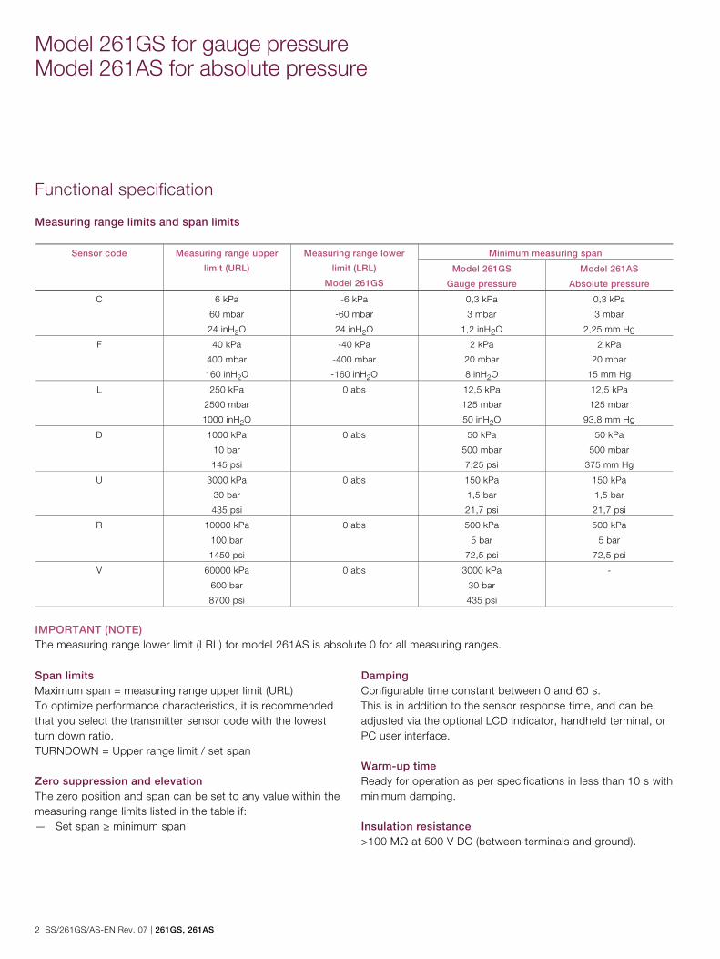
Functional specification
Measuring range limits and span limits
Sensor code Measuring range upper
limit (URL)
Measuring range lower
limit (LRL)
Model 261GS
Minimum measuring span
Model 261GS
Gauge pressure
Model 261AS
Absolute pressure
C 6 kPa
60 mbar
24 inH2O
-6 kPa
-60 mbar
24 inH2O
0,3 kPa
3 mbar
1,2 inH2O
0,3 kPa
3 mbar
2,25 mm Hg
F 40 kPa
400 mbar
160 inH2O
-40 kPa
-400 mbar
-160 inH2O
2 kPa
20 mbar
8 inH2O
2 kPa
20 mbar
15 mm Hg
L 250 kPa
2500 mbar
1000 inH2O
0 abs 12,5 kPa
125 mbar
50 inH2O
12,5 kPa
125 mbar
93,8 mm Hg
D 1000 kPa
10 bar
145 psi
0 abs 50 kPa
500 mbar
7,25 psi
50 kPa
500 mbar
375 mm Hg
U 3000 kPa
30 bar
435 psi
0 abs 150 kPa
1,5 bar
21,7 psi
150 kPa
1,5 bar
21,7 psi
R 10000 kPa
100 bar
1450 psi
0 abs 500 kPa
5 bar
72,5 psi
500 kPa
5 bar
72,5 psi
V 60000 kPa
600 bar
8700 psi
0 abs 3000 kPa
30 bar
435 psi
-
IMPORTANT (NOTE) The measuring range lower limit (LRL) for model 261AS is absolute 0 for all measuring ranges. Change from one to two columns
Span limits Maximum span = measuring range upper limit (URL) To optimize performance characteristics, it is recommended that you select the transmitter sensor code with the lowest turn down ratio. TURNDOWN = Upper range limit / set span Zero suppression and elevation The zero position and span can be set to any value within the measuring range limits listed in the table if: — Set span ≥ minimum span
Damping Configurable time constant between 0 and 60 s. This is in addition to the sensor response time, and can be adjusted via the optional LCD indicator, handheld terminal, or PC user interface. Warm-up time Ready for operation as per specifications in less than 10 s with minimum damping. Insulation resistance >100 MΩ at 500 V DC (between terminals and ground).
261GS, 261AS | SS/261GS/AS-EN Rev. 07 3
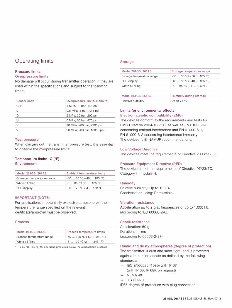
Operating limits
Pressure limits Overpressure limits No damage will occur during transmitter operation, if they are used within the specifications and subject to the following limits: Sensor code Overpressure limits, 0 abs to:
C, F 1 MPa, 10 bar, 145 psi
L 0.5 MPa, 5 bar, 72.5 psi
D 2 MPa, 20 bar, 290 psi
U 6 MPa, 60 bar, 870 psi
R 20 MPa, 200 bar, 2900 psi
V 90 MPa, 900 bar, 13050 psi
Test pressure When carrying out the transmitter pressure test, it is essential to observe the overpressure limits! Temperature limits °C (°F) Environment Model 261GS, 261AS Ambient temperature limits
Operating temperature range -40 … 85 °C (-40 … 185 °F)
White oil filling -6 … 85 °C (21 … 185 °F)
LCD display -20 … 70 °C (-4 … 158 °F)
IMPORTANT (NOTE) For applications in potentially explosive atmospheres, the temperature range specified on the relevant certificate/approval must be observed. Process Model 261GS, 261AS Process temperature limits
Process temperature range -50 … 120 °C (-58 … 248 °F)
White oil filling -6 … 120 °C (21 … 248 °F)1
1 ≤ 85 °C (185 °F) for operating pressures below the atmospheric pressure
Storage Model 261GS, 261AS Storage temperature range
Storage temperature range -50 … 85 °C (-58 … 185 °F)
LCD display -40 … 85 °C (-40 … 185 °F)
White oil filling -6 … 85 °C (21 … 185 °F)
Model 261GS, 261AS Humidity during storage
Relative humidity Up to 75 %
Limits for environmental effects Electromagnetic compatibility (EMC) The devices conform to the requirements and tests for EMC Directive 2004/108/EC, as well as EN 61000-6-3 concerning emitted interference and EN 61000-6-1, EN 61000-6-2 concerning interference immunity. The devices fulfill NAMUR recommendations. Low Voltage Directive The devices meet the requirements of Directive 2006/95/EC. Pressure Equipment Directive (PED) The devices meet the requirements of Directive 97/23/EC, Category III, module H. Humidity Relative humidity: Up to 100 % Condensation, icing: Permissible Vibration resistance Acceleration up to 2 g at frequencies of up to 1,000 Hz (according to IEC 60068-2-6). Shock resistance Acceleration: 50 g Duration: 11 ms (according to 60068-2-27) Humid and dusty atmospheres (degree of protection) The transmitter is dust and sand-tight, and is protected against immersion effects as defined by the following standards: — IEC EN60529 (1989) with IP 67
(with IP 68, IP 69K on request) — NEMA 4X — JIS C0920 IP65 degree of protection with plug connection
Model 261GS for gauge pressure Model 261AS for absolute pressure
4 SS/261GS/AS-EN Rev. 07 | 261GS, 261AS
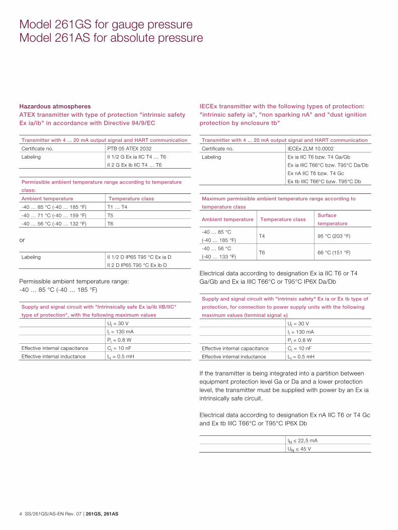
Hazardous atmospheres ATEX transmitter with type of protection "intrinsic safety Ex ia/ib" in accordance with Directive 94/9/EC Transmitter with 4 ... 20 mA output signal and HART communication
Certificate no. PTB 05 ATEX 2032
Labeling II 1/2 G Ex ia IIC T4 … T6
II 2 G Ex ib IIC T4 … T6
Permissible ambient temperature range according to temperature
class:
Ambient temperature Temperature class
-40 … 85 °C (-40 … 185 °F) T1 … T4
-40 … 71 °C (-40 … 159 °F) T5
-40 … 56 °C (-40 … 132 °F) T6
or Labeling II 1/2 D IP65 T95 °C Ex ia D
II 2 D IP65 T95 °C Ex ib D
Permissible ambient temperature range: -40 … 85 °C (-40 … 185 °F) Supply and signal circuit with "Intrinsically safe Ex ia/ib IIB/IIC"
type of protection", with the following maximum values
Ui = 30 V
Ii = 130 mA
Pi = 0.8 W
Effective internal capacitance Ci = 10 nF
Effective internal inductance Li = 0.5 mH
IECEx transmitter with the following types of protection: "intrinsic safety ia", "non sparking nA" and "dust ignition protection by enclosure tb" Transmitter with 4 ... 20 mA output signal and HART communication
Certificate no. IECEx ZLM 10.0002
Labeling Ex ia IIC T6 bzw. T4 Ga/Gb
Ex ia IIIC T66°C bzw. T95°C Da/Db
Ex nA IIC T6 bzw. T4 Gc
Ex tb IIIC T66°C bzw. T95°C Db
Maximum permissible ambient temperature range according to
temperature class
Ambient temperature Temperature class Surface
temperature
-40 … 85 °C
(-40 … 185 °F) T4 95 °C (203 °F)
-40 … 56 °C
(-40 … 133 °F) T6 66 °C (151 °F)
Electrical data according to designation Ex ia IIC T6 or T4 Ga/Gb and Ex ia IIIC T66°C or T95°C IP6X Da/Db Supply and signal circuit with "intrinsic safety" Ex ia or Ex ib type of
protection, for connection to power supply units with the following
maximum values (terminal signal ±)
Ui = 30 V
Ii = 130 mA
Pi = 0.8 W
Effective internal capacitance Ci = 10 nF
Effective internal inductance Li = 0.5 mH
If the transmitter is being integrated into a partition between equipment protection level Ga or Da and a lower protection level, the transmitter must be supplied with power by an Ex ia intrinsically safe circuit. Electrical data according to designation Ex nA IIC T6 or T4 Gc and Ex tb IIIC T66°C or T95°C IP6X Db IN ≤ 22,5 mA
UN ≤ 45 V
261GS, 261AS | SS/261GS/AS-EN Rev. 07 5
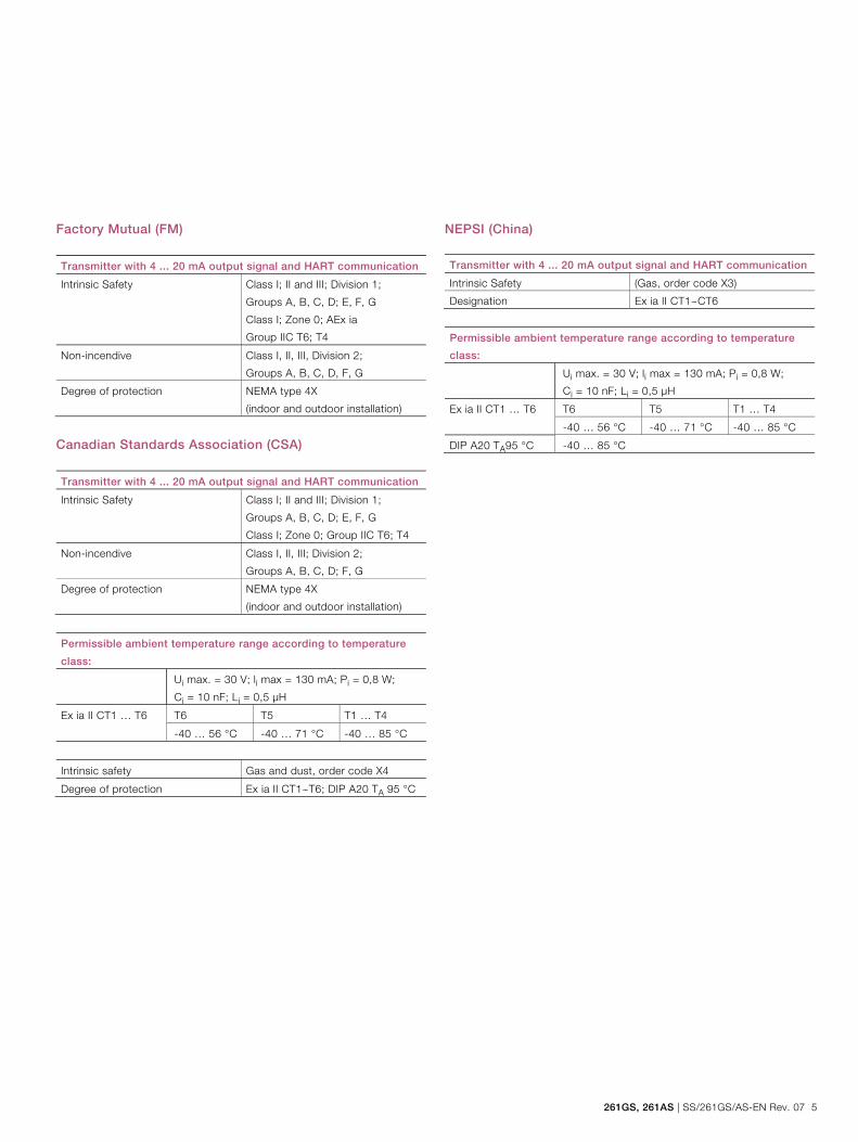
Factory Mutual (FM) Transmitter with 4 ... 20 mA output signal and HART communication
Intrinsic Safety Class I; II and III; Division 1;
Groups A, B, C, D; E, F, G
Class I; Zone 0; AEx ia
Group IIC T6; T4
Non-incendive Class I, II, III, Division 2;
Groups A, B, C, D, F, G
Degree of protection NEMA type 4X
(indoor and outdoor installation)
Canadian Standards Association (CSA) Transmitter with 4 ... 20 mA output signal and HART communication
Intrinsic Safety Class I; II and III; Division 1;
Groups A, B, C, D; E, F, G
Class I; Zone 0; Group IIC T6; T4
Non-incendive Class I, II, III; Division 2;
Groups A, B, C, D; F, G
Degree of protection NEMA type 4X
(indoor and outdoor installation)
Permissible ambient temperature range according to temperature
class:
Ui max. = 30 V; li max = 130 mA; Pi = 0,8 W;
Ci = 10 nF; Li = 0,5 μH
Ex ia II CT1 … T6 T6 T5 T1 … T4
-40 … 56 °C -40 … 71 °C -40 … 85 °C
Intrinsic safety Gas and dust, order code X4
Degree of protection Ex ia II CT1~T6; DIP A20 TA 95 °C
NEPSI (China) Transmitter with 4 ... 20 mA output signal and HART communication
Intrinsic Safety (Gas, order code X3)
Designation Ex ia II CT1~CT6
Permissible ambient temperature range according to temperature
class:
Ui max. = 30 V; li max = 130 mA; Pi = 0,8 W;
Ci = 10 nF; Li = 0,5 μH
Ex ia II CT1 … T6 T6 T5 T1 … T4
-40 … 56 °C -40 … 71 °C -40 … 85 °C
DIP A20 TA95 °C -40 … 85 °C

Model 261GS for gauge pressure Model 261AS for absolute pressure
6 SS/261GS/AS-EN Rev. 07 | 261GS, 261AS
Electrical data and options
HART digital communication and 4 ... 20 mA output Power supply The transmitter operates from 11 ... 42 V DC with no load and is protected against reversed polarity (additional loads enable operation above 42 V DC). During use in Ex ia zones and in other intrinsically safe applications, the power supply must not exceed 30 V DC. Ripple Maximum permissible supply voltage ripple during communication: Complies with HART FSK “Physical Layer” specification rev. 8.1. Load limitations Total loop resistance at 4 ... 20 mA and HART:
mA6.23
)VDC(voltageoperatingMinimumplysupVoltage)k(R
A minimum resistance of 250 Ω is required for HART communication. LCD display (optional) Digital, graphic LCD display for customized visualization of: — Gauge pressure/absolute pressure — Output current in mA or %, or — HART output (freely assigned start/end values and unit) Diagnostic messages, alarms, errors, and measuring range upper limit violations are also displayed. In addition, the LCD display can be used to configure and parameterize the transmitter using 4 buttons.
Output signal Two-wire, 4 ... 20 mA output. HART® communication provides digital process variables (%, mA or engineering units) superimposed on the 4 ... 20 mA signal (protocol according to Bell 202 FSK standard). Output current limits (according to NAMUR standard) Overload condition — Lower limit: 3.8 mA (configurable up to 3.5 mA) — Upper limit: 20.5 mA (configurable up to 23.6 mA) Alarm current — Minimum alarm current: 3.5 mA (configurable from
3.5 … 4 mA) — Maximum alarm current: 21 mA (configurable from
20 … 23.6 mA) Default setting: High Alarm Current SIL: Functional safety (optional) According to IEC 61508/61511 Device with certificate of conformity for use in safety-related applications, up to and including SIL 2.
261GS, 261AS | SS/261GS/AS-EN Rev. 07 7
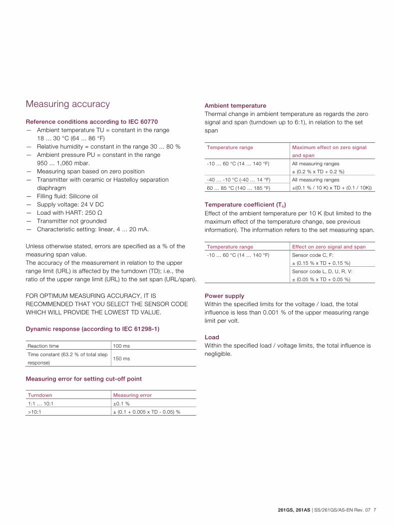
Measuring accuracy
Reference conditions according to IEC 60770 — Ambient temperature TU = constant in the range
18 ... 30 °C (64 ... 86 °F) — Relative humidity = constant in the range 30 ... 80 % — Ambient pressure PU = constant in the range
950 ... 1,060 mbar. — Measuring span based on zero position — Transmitter with ceramic or Hastelloy separation
diaphragm — Filling fluid: Silicone oil — Supply voltage: 24 V DC — Load with HART: 250 Ω — Transmitter not grounded — Characteristic setting: linear, 4 ... 20 mA. Unless otherwise stated, errors are specified as a % of the measuring span value. The accuracy of the measurement in relation to the upper range limit (URL) is affected by the turndown (TD); i.e., the ratio of the upper range limit (URL) to the set span (URL/span). FOR OPTIMUM MEASURING ACCURACY, IT IS RECOMMENDED THAT YOU SELECT THE SENSOR CODE WHICH WILL PROVIDE THE LOWEST TD VALUE. Dynamic response (according to IEC 61298-1) Reaction time 100 ms
Time constant (63.2 % of total step
response) 150 ms
Measuring error for setting cut-off point
Turndown Measuring error
1:1 … 10:1 ±0.1 %
>10:1 ± (0.1 + 0.005 x TD - 0.05) %
Ambient temperature Thermal change in ambient temperature as regards the zero signal and span (turndown up to 6:1), in relation to the set span Temperature range Maximum effect on zero signal
and span
-10 … 60 °C (14 … 140 °F) All measuring ranges
± (0.2 % x TD + 0.2 %)
-40 … -10 °C (-40 … 14 °F) All measuring ranges
±((0.1 % / 10 K) x TD + (0.1 / 10K)) 60 … 85 °C (140 … 185 °F)
Temperature coefficient (Tk)
Effect of the ambient temperature per 10 K (but limited to the maximum effect of the temperature change, see previous information). The information refers to the set measuring span. Temperature range Effect on zero signal and span
-10 … 60 °C (14 … 140 °F) Sensor code C, F:
± (0.15 % x TD + 0.15 %)
Sensor code L, D, U, R, V:
± (0.05 % x TD + 0.05 %)
Power supply Within the specified limits for the voltage / load, the total influence is less than 0.001 % of the upper measuring range limit per volt. Load Within the specified load / voltage limits, the total influence is negligible.
Model 261GS for gauge pressure Model 261AS for absolute pressure
8 SS/261GS/AS-EN Rev. 07 | 261GS, 261AS
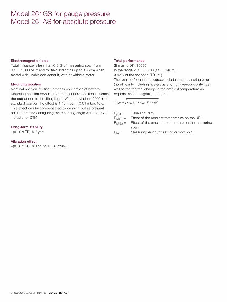
Electromagnetic fields Total influence is less than 0.3 % of measuring span from 80 … 1,000 MHz and for field strengths up to 10 V/m when tested with unshielded conduit, with or without meter. Mounting position Nominal position: vertical; process connection at bottom. Mounting position deviant from the standard position influence the output due to the filling liquid. With a deviation of 90° from standard position the effect is 1.12 mbar + 0.01 mbar/10K. This effect can be compensated by carrying out zero signal adjustment and configuring the mounting angle with the LCD indicator or DTM. Long-term stability ±(0.10 x TD) % / year Vibration effect ±(0.10 x TD) % acc. to IEC 61298-3
Total performance Similar to DIN 16086 In the range -10 … 60 °C (14 … 140 °F): 0.42% of the set span (TD 1:1) The total performance accuracy includes the measuring error (non-linearity including hysteresis and non-reproducibility), as well as the thermal change in the ambient temperature as regards the zero signal and span.
2221 )( linTSTSperf EEEE
Eperf = Base accuracy EΔTS1 = Effect of the ambient temperature on the URL EΔTS2 = Effect of the ambient temperature on the measuring
span Elin = Measuring error (for setting cut-off point)
261GS, 261AS | SS/261GS/AS-EN Rev. 07 9
Technical specification
(Please refer to the order information to check the availability of different versions of the relevant model)
Materials
Process separation diaphragms1
Hastelloy C276, Hastelloy C276 gold plated, Stainless steel (1.4435 / 316L) Process connection1 Stainless steel (1.4404 / 316L) Sensor filling fluid Silicone oil, inert fill (fluorocarbon), white oil (FDA) Mounting bracket Stainless steel Sensor housing, electronics housing and cover Stainless steel (1.4404 / 316L) Filter for atmospheric ventilation Filter housing: plastic (standard), stainless steel (code EA, AB) Filter material: polyamide (PA) Viewing window in cover (LCD display) Polycarbonate, Makrolon 6557 Cover O-ring EPDM Plates Plastic data plate attached to the electronics housing
1 Wetted parts of the transmitter.
Calibration Standard: — 0 to upper range limit (URL) Optional: — To specified measuring span
Optional extras Mounting bracket For vertical and horizontal 60 mm (2 in.) pipes or wall mounting LCD display Can be rotated in 90° increments into 4 positions Additional tag plates Code I2: For measuring point tag (up to 30 characters) and calibration specifications (up to 30 characters: lower and upper value plus unit), attached to transmitter housing. Code I1: For customer data (4 lines with 30 characters each), attached to transmitter housing with wire. Cleaning stage for oxygen applications (O2) Certificates (test, design, characteristics, material traceability ) Name plate and operating instruction language Communication plug connectors Process connections 1/2-14 NPT female or male thread, DIN EN 837-1 G 1/2 B or G 1/2 B (HP) for convex seal, flush diaphragm, for installation in ball valve.
Model 261GS for gauge pressure Model 261AS for absolute pressure
10 SS/261GS/AS-EN Rev. 07 | 261GS, 261AS
Electrical connections
M16 x 1.5 tap hole with cable gland (cable diameter approx. 5 … 10 mm), directly on housing or M20 x 1.5 (via adapter) with cable gland (cable diameter approx. 6 … 11 mm) or 1/2-14 NPT (via adapter) without cable gland or Harting Han plug connector (with mating plug (socket outlet, for wire diameters of 0.75 … 1 mm2 and cable diameters of 5 … 11 mm)) or Miniature plug connector (without mating plug (socket outlet)) Terminals HART version: Two connections for signal / auxiliary power, for wire cross-sections from 0.5 … 1.5 mm2 (16 AWG) Grounding (optional) External ground terminals for wire cross-sections up to 4 mm2 (12 AWG). Weight (without options) — Approx. 0.7 kg (1.54 lb) — Additional 650 G (1.5 lb) Packaging Carton with dimensions of approx. 240 x 140 x 190 mm (9.45 x 5.51 x 7.48 in.)
Configuration
Transmitter with HART communication and 4 … 20 mA Standard configuration Transmitters are set to the customer's specified span at the factory. The set range and measuring point number are provided on the name plate. If this data has not been specified, the transmitter will be delivered with the following configuration: Parameter Factory setting
4 mA Zero position
20 mA Measuring range upper limit (URL)
Output Linear
Damping 0.1 s
Transmitter failure mode 21 mA
Optional LCD display 0 … 100 %
Any or all of the configurable parameters listed above - including the upper and lower range values - can easily be changed using the optional LCD indicator, a HART handheld communicator, or a PC running the configuration software SMART VISION with DTM for 2600T.
261GS, 261AS | SS/261GS/AS-EN Rev. 07 11
Change from two to one column
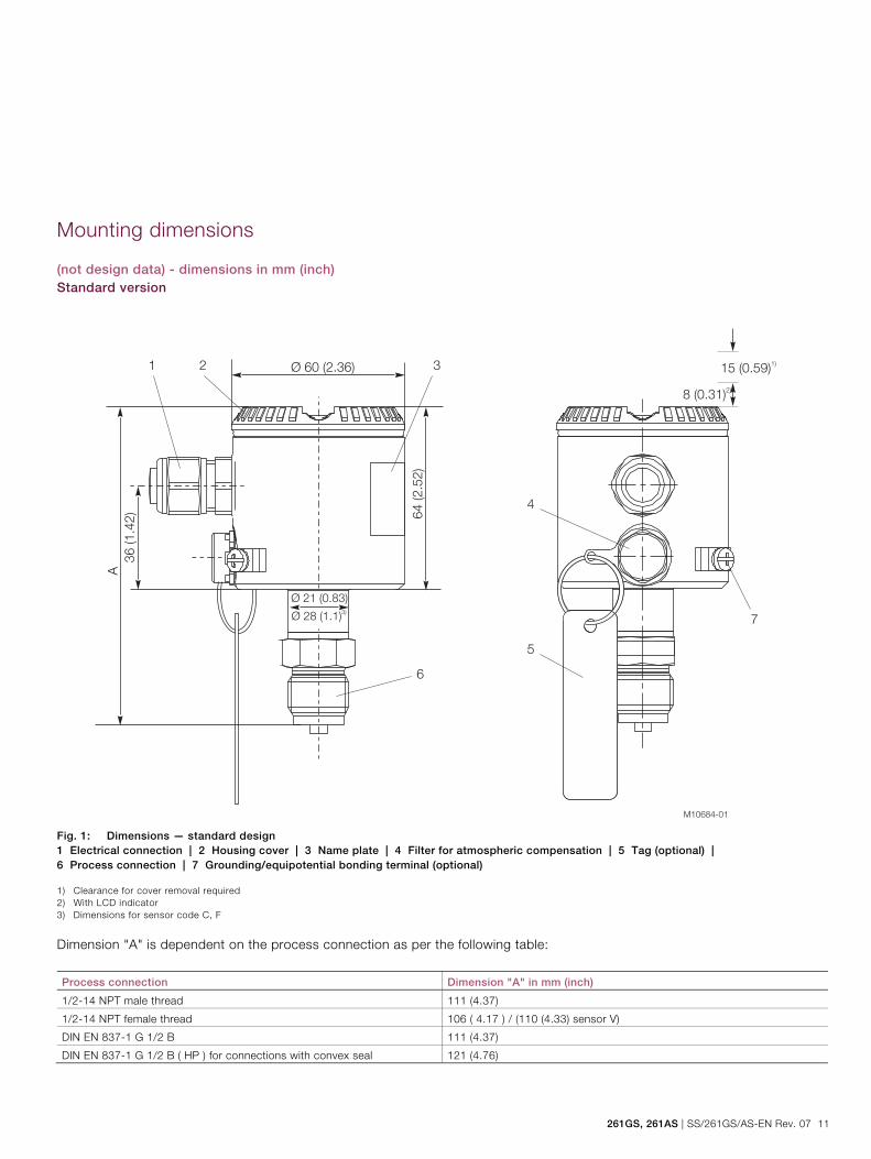
Mounting dimensions
(not design data) - dimensions in mm (inch) Standard version
Fig. 1: Dimensions — standard design 1 Electrical connection | 2 Housing cover | 3 Name plate | 4 Filter for atmospheric compensation | 5 Tag (optional) | 6 Process connection | 7 Grounding/equipotential bonding terminal (optional) 1) Clearance for cover removal required 2) With LCD indicator 3) Dimensions for sensor code C, F Dimension "A" is dependent on the process connection as per the following table: Process connection Dimension "A" in mm (inch)
1/2-14 NPT male thread 111 (4.37)
1/2-14 NPT female thread 106 ( 4.17 ) / (110 (4.33) sensor V)
DIN EN 837-1 G 1/2 B 111 (4.37)
DIN EN 837-1 G 1/2 B ( HP ) for connections with convex seal 121 (4.76)
M10684-01
1 2
4
5
3
6
7
Ø 60 (2.36) 15 (0.59)1)
8 (0.31)2)
36
(1
.42
)
A
Ø 21 (0.83)
64
(2
.52
)
Ø 28 (1.1)3)
Model 261GS for gauge pressure Model 261AS for absolute pressure
12 SS/261GS/AS-EN Rev. 07 | 261GS, 261AS
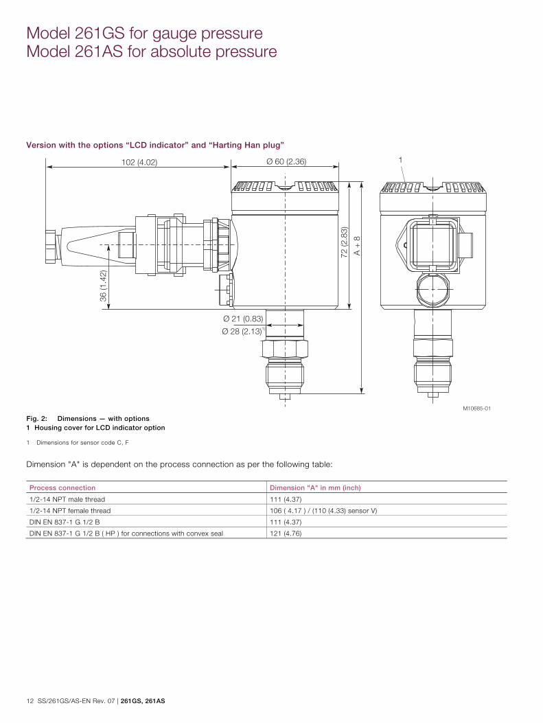
Version with the options “LCD indicator” and “Harting Han plug”
Fig. 2: Dimensions — with options 1 Housing cover for LCD indicator option 1 Dimensions for sensor code C, F
Dimension "A" is dependent on the process connection as per the following table: Process connection Dimension "A" in mm (inch)
1/2-14 NPT male thread 111 (4.37)
1/2-14 NPT female thread 106 ( 4.17 ) / (110 (4.33) sensor V)
DIN EN 837-1 G 1/2 B 111 (4.37)
DIN EN 837-1 G 1/2 B ( HP ) for connections with convex seal 121 (4.76)
M10685-01
Ø 60 (2.36)102 (4.02)
72 (2.8
3)
36 (1.4
2)
A +
8
Ø 21 (0.83)
Ø 28 (2.13)1)
1
261GS, 261AS | SS/261GS/AS-EN Rev. 07 13
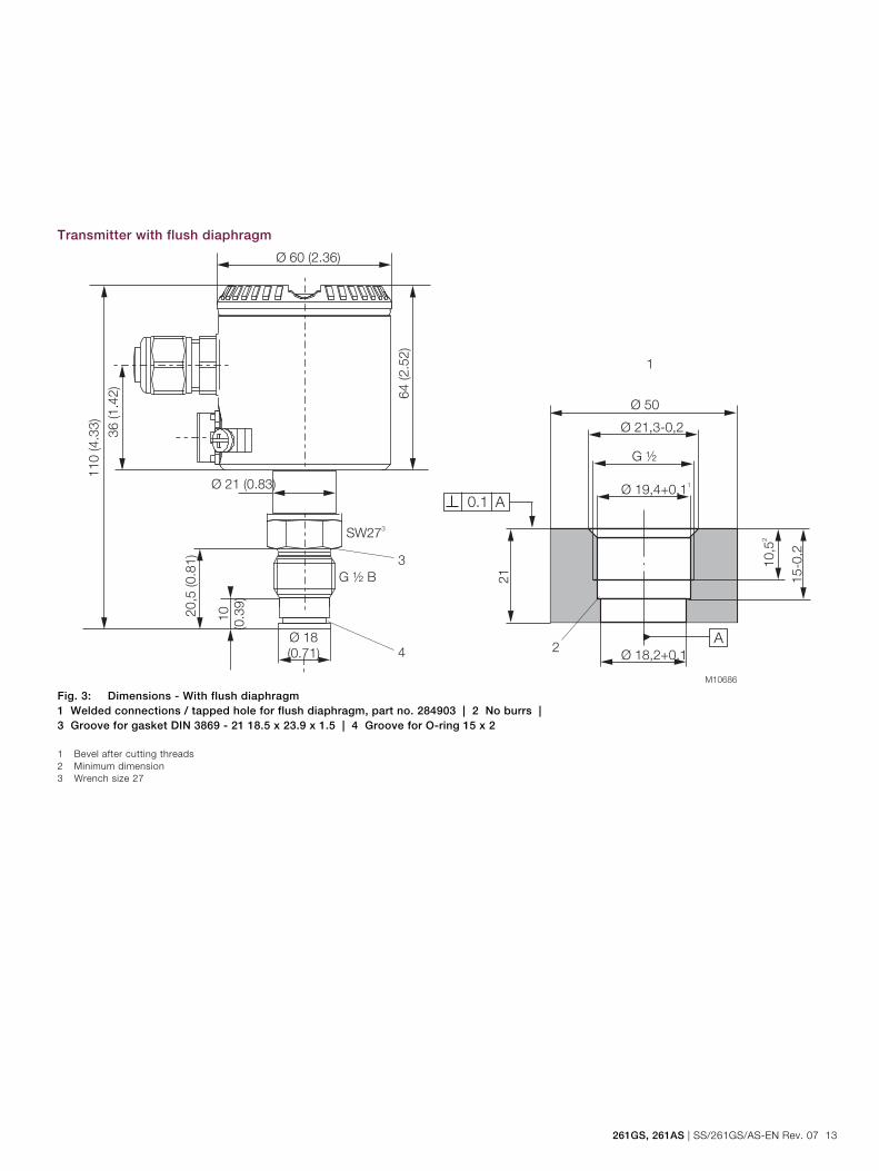
Transmitter with flush diaphragm
Fig. 3: Dimensions - With flush diaphragm 1 Welded connections / tapped hole for flush diaphragm, part no. 284903 | 2 No burrs | 3 Groove for gasket DIN 3869 - 21 18.5 x 23.9 x 1.5 | 4 Groove for O-ring 15 x 2 1 Bevel after cutting threads 2 Minimum dimension 3 Wrench size 27
Model 261GS for gauge pressure Model 261AS for absolute pressure
14 SS/261GS/AS-EN Rev. 07 | 261GS, 261AS
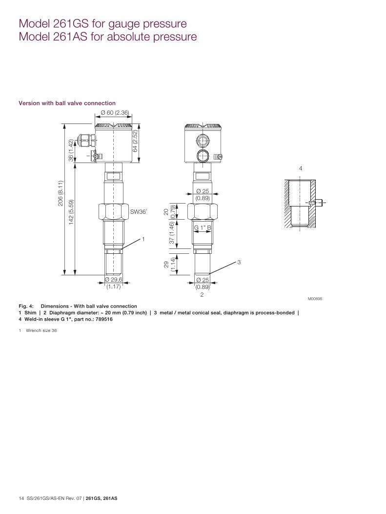
Version with ball valve connection
Fig. 4: Dimensions - With ball valve connection 1 Shim | 2 Diaphragm diameter: ~ 20 mm (0.79 inch) | 3 metal / metal conical seal, diaphragm is process-bonded | 4 Weld-in sleeve G 1", part no.: 789516 1 Wrench size 36
261GS, 261AS | SS/261GS/AS-EN Rev. 07 15
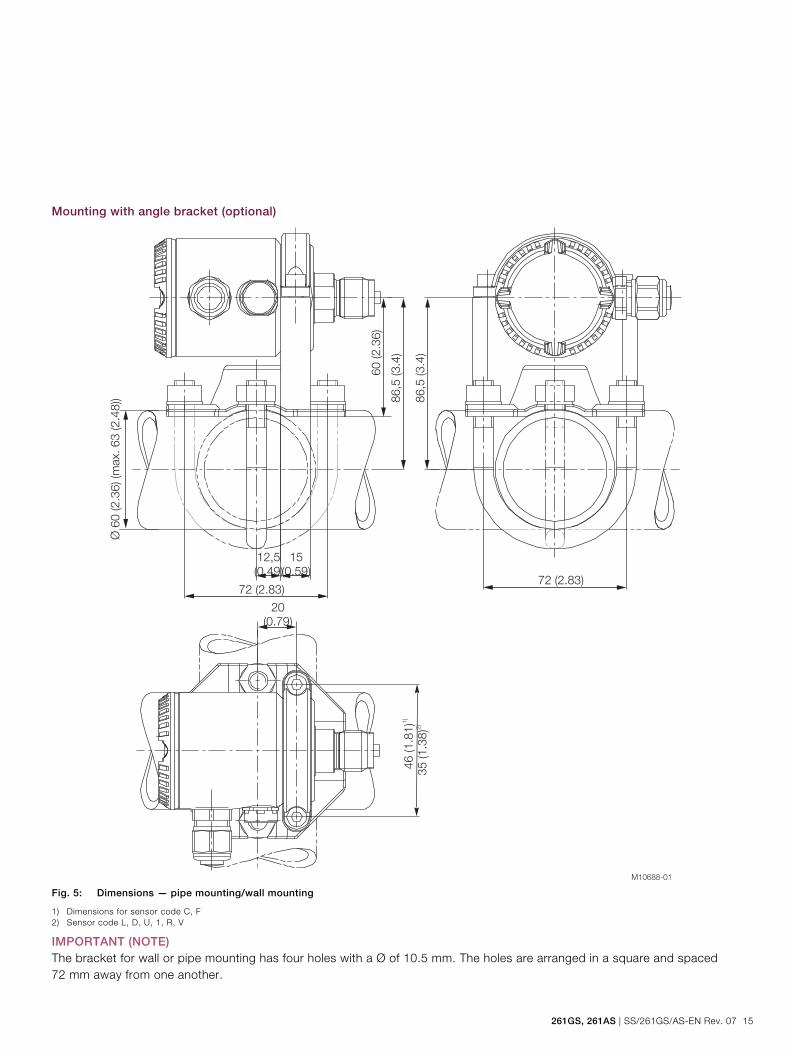
Mounting with angle bracket (optional)
Fig. 5: Dimensions — pipe mounting/wall mounting
1) Dimensions for sensor code C, F 2) Sensor code L, D, U, 1, R, V
IMPORTANT (NOTE) The bracket for wall or pipe mounting has four holes with a Ø of 10.5 mm. The holes are arranged in a square and spaced 72 mm away from one another.
M10688-01
35 (1.3
8)2
)
20
(0.79)
12,5
(0.49)
15
(0.59)
72 (2.83)
86,5
(3.4
)
Ø 6
0 (2.3
6) (m
ax. 63 (2.4
8)) 8
6,5
(3.4
)
72 (2.83)
46 (1.8
1)1
)
60 (2.3
6)
Model 261GS for gauge pressure Model 261AS for absolute pressure
16 SS/261GS/AS-EN Rev. 07 | 261GS, 261AS
Electrical connections
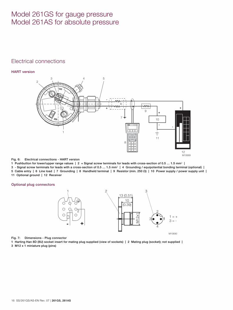
HART version
Fig. 6: Electrical connections - HART version 1 Pushbutton for lower/upper range values | 2 + Signal screw terminals for leads with cross-section of 0.5 … 1.5 mm2 | 3 - Signal screw terminals for leads with a cross-section of 0.5 … 1.5 mm2 | 4 Grounding / equipotential bonding terminal (optional) | 5 Cable entry | 6 Line load | 7 Grounding | 8 Handheld terminal | 9 Resistor (min. 250 Ω) | 10 Power supply / power supply unit | 11 Optional ground | 12 Receiver
Optional plug connectors
Fig. 7: Dimensions - Plug connector 1 Harting Han 8D (8U) socket insert for mating plug supplied (view of sockets) | 2 Mating plug (socket); not supplied | 3 M12 x 1 miniature plug (pins)
261GS, 261AS | SS/261GS/AS-EN Rev. 07 17
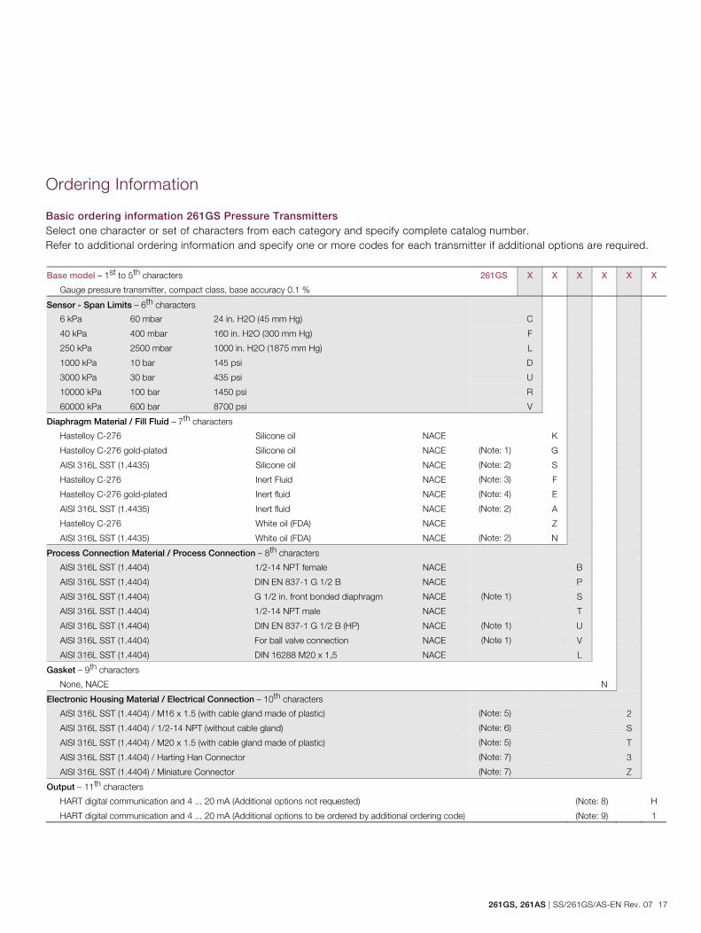
Ordering Information
Basic ordering information 261GS Pressure Transmitters Select one character or set of characters from each category and specify complete catalog number. Refer to additional ordering information and specify one or more codes for each transmitter if additional options are required. Base model – 1st to 5th characters
Gauge pressure transmitter, compact class, base accuracy 0.1 %
261GS X X X X X X
Sensor - Span Limits – 6th characters
6 kPa 60 mbar 24 in. H2O (45 mm Hg) C
40 kPa 400 mbar 160 in. H2O (300 mm Hg) F
250 kPa 2500 mbar 1000 in. H2O (1875 mm Hg) L
1000 kPa 10 bar 145 psi D
3000 kPa 30 bar 435 psi U
10000 kPa 100 bar 1450 psi R
60000 kPa 600 bar 8700 psi V
Diaphragm Material / Fill Fluid – 7th characters
Hastelloy C-276 Silicone oil NACE K
Hastelloy C-276 gold-plated Silicone oil NACE (Note: 1) G
AISI 316L SST (1.4435) Silicone oil NACE (Note: 2) S
Hastelloy C-276 Inert Fluid NACE (Note: 3) F
Hastelloy C-276 gold-plated Inert fluid NACE (Note: 4) E
AISI 316L SST (1.4435) Inert fluid NACE (Note: 2) A
Hastelloy C-276 White oil (FDA) NACE Z
AISI 316L SST (1.4435) White oil (FDA) NACE (Note: 2) N
Process Connection Material / Process Connection – 8th characters
AISI 316L SST (1.4404) 1/2-14 NPT female NACE B
AISI 316L SST (1.4404) DIN EN 837-1 G 1/2 B NACE P
AISI 316L SST (1.4404) G 1/2 in. front bonded diaphragm NACE (Note 1) S
AISI 316L SST (1.4404) 1/2-14 NPT male NACE T
AISI 316L SST (1.4404) DIN EN 837-1 G 1/2 B (HP) NACE (Note 1) U
AISI 316L SST (1.4404) For ball valve connection NACE (Note 1) V
AISI 316L SST (1.4404) DIN 16288 M20 x 1,5 NACE L
Gasket – 9th characters
None, NACE N
Electronic Housing Material / Electrical Connection – 10th characters
AISI 316L SST (1.4404) / M16 x 1.5 (with cable gland made of plastic) (Note: 5) 2
AISI 316L SST (1.4404) / 1/2-14 NPT (without cable gland) (Note: 6) S
AISI 316L SST (1.4404) / M20 x 1.5 (with cable gland made of plastic) (Note: 5) T
AISI 316L SST (1.4404) / Harting Han Connector (Note: 7) 3
AISI 316L SST (1.4404) / Miniature Connector (Note: 7) Z
Output – 11th characters
HART digital communication and 4 ... 20 mA (Additional options not requested) (Note: 8) H
HART digital communication and 4 ... 20 mA (Additional options to be ordered by additional ordering code) (Note: 9) 1
Model 261GS for gauge pressure Model 261AS for absolute pressure
18 SS/261GS/AS-EN Rev. 07 | 261GS, 261AS
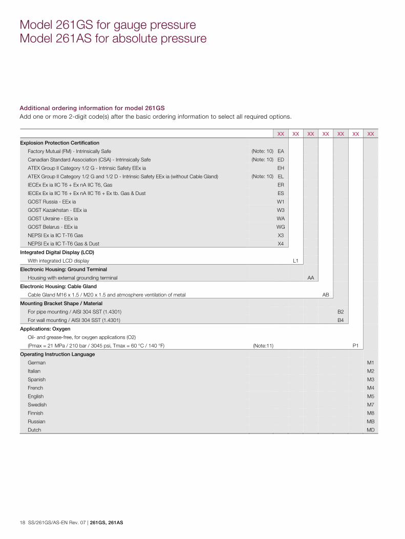
Additional ordering information for model 261GS Add one or more 2-digit code(s) after the basic ordering information to select all required options. XX XX XX XX XX XX XX
Explosion Protection Certification
Factory Mutual (FM) - Intrinsically Safe (Note: 10) EA
Canadian Standard Association (CSA) - Intrinsically Safe (Note: 10) ED
ATEX Group II Category 1/2 G - Intrinsic Safety EEx ia EH
ATEX Group II Category 1/2 G and 1/2 D - Intrinsic Safety EEx ia (without Cable Gland) (Note: 10) EL
IECEx Ex ia IIC T6 + Ex nA IIC T6, Gas ER
IECEx Ex ia IIC T6 + Ex nA IIC T6 + Ex tb. Gas & Dust ES
GOST Russia - EEx ia W1
GOST Kazakhstan - EEx ia W3
GOST Ukraine - EEx ia WA
GOST Belarus - EEx ia WG
NEPSI Ex ia llC T-T6 Gas X3
NEPSI Ex ia llC T-T6 Gas & Dust X4
Integrated Digital Display (LCD)
With integrated LCD display L1
Electronic Housing: Ground Terminal
Housing with external grounding terminal AA
Electronic Housing: Cable Gland
Cable Gland M16 x 1.5 / M20 x 1.5 and atmosphere ventilation of metal AB
Mounting Bracket Shape / Material
For pipe mounting / AISI 304 SST (1.4301) B2
For wall mounting / AISI 304 SST (1.4301) B4
Applications: Oxygen
Oil- and grease-free, for oxygen applications (O2)
(Pmax = 21 MPa / 210 bar / 3045 psi, Tmax = 60 °C / 140 °F) (Note:11) P1
Operating Instruction Language
German M1
Italian M2
Spanish M3
French M4
English M5
Swedish M7
Finnish M8
Russian MB
Dutch MD
261GS, 261AS | SS/261GS/AS-EN Rev. 07 19
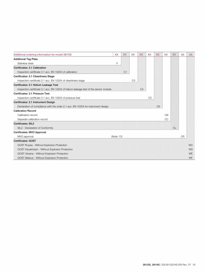
Additional ordering information for model 261GS XX XX XX XX XX XX XX XX XX XX
Additional Tag Plate
Stainless steel I1
Certificates: 3.1 Calibration
Inspection certificate 3.1 acc. EN 10204 of calibration C1
Certificates: 3.1 Cleanliness Stage
Inspection certificate 3.1 acc. EN 10204 of cleanliness stage C3
Certificates: 3.1 Helium Leakage Test
Inspection certificate 3.1 acc. EN 10204 of helium leakage test of the sensor module C4
Certificates: 3.1 Pressure Test
Inspection certificate 3.1 acc. EN 10204 of pressure test C5
Certificates: 2.1 Instrument Design
Declaration of compliance with the order 2.1 acc. EN 10204 for instrument design C6
Calibration Record
Calibration record CB
Separate calibration record CC
Certificates: SIL2
SIL2 - Declaration of Conformity CL
Certificates: MVO Approval
MVO approval (Note: 12) CR
Certificates: GOST
GOST Russia - Without Explosion Protection WC
GOST Kazakhstan - Without Explosion Protection WD
GOST Ukraine - Without Explosion Protection WE
GOST Belarus - Without Explosion Protection WF
Model 261GS for gauge pressure Model 261AS for absolute pressure
20 SS/261GS/AS-EN Rev. 07 | 261GS, 261AS
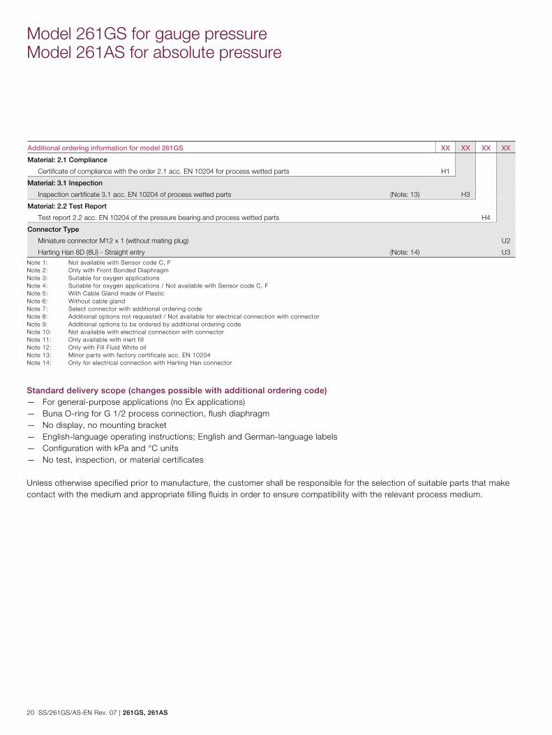
Additional ordering information for model 261GS XX XX XX XX
Material: 2.1 Compliance
Certificate of compliance with the order 2.1 acc. EN 10204 for process wetted parts H1
Material: 3.1 Inspection
Inspection certificate 3.1 acc. EN 10204 of process wetted parts (Note: 13) H3
Material: 2.2 Test Report
Test report 2.2 acc. EN 10204 of the pressure bearing and process wetted parts H4
Connector Type
Miniature connector M12 x 1 (without mating plug) U2
Harting Han 8D (8U) - Straight entry (Note: 14) U3
Note 1: Not available with Sensor code C, F Note 2: Only with Front Bonded Diaphragm Note 3: Suitable for oxygen applications Note 4: Suitable for oxygen applications / Not available with Sensor code C, F Note 5: With Cable Gland made of Plastic Note 6: Without cable gland Note 7: Select connector with additional ordering code Note 8: Additional options not requested / Not available for electrical connection with connector Note 9: Additional options to be ordered by additional ordering code Note 10: Not available with electrical connection with connector Note 11: Only available with inert fill Note 12: Only with Fill Fluid White oil Note 13: Minor parts with factory certificate acc. EN 10204 Note 14: Only for electrical connection with Harting Han connector
Standard delivery scope (changes possible with additional ordering code) — For general-purpose applications (no Ex applications) — Buna O-ring for G 1/2 process connection, flush diaphragm — No display, no mounting bracket — English-language operating instructions; English and German-language labels — Configuration with kPa and °C units — No test, inspection, or material certificates Unless otherwise specified prior to manufacture, the customer shall be responsible for the selection of suitable parts that make contact with the medium and appropriate filling fluids in order to ensure compatibility with the relevant process medium.
261GS, 261AS | SS/261GS/AS-EN Rev. 07 21
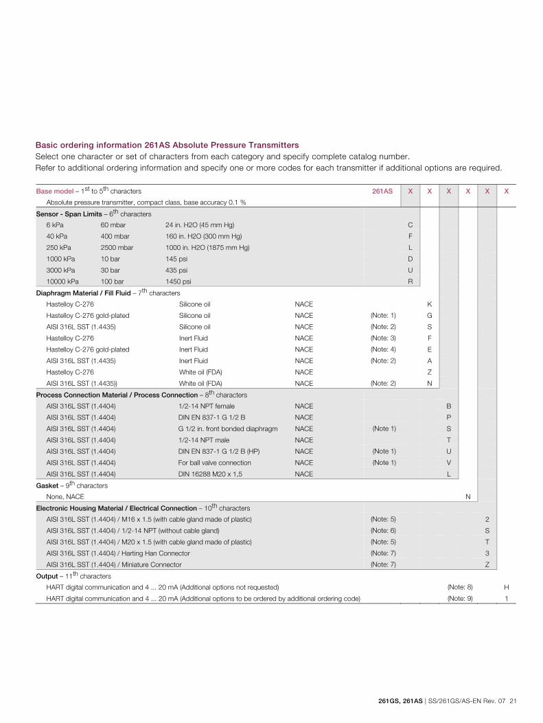
Basic ordering information 261AS Absolute Pressure Transmitters Select one character or set of characters from each category and specify complete catalog number. Refer to additional ordering information and specify one or more codes for each transmitter if additional options are required. Base model – 1st to 5th characters
Absolute pressure transmitter, compact class, base accuracy 0.1 %
261AS X X X X X X
Sensor - Span Limits – 6th characters
6 kPa 60 mbar 24 in. H2O (45 mm Hg) C
40 kPa 400 mbar 160 in. H2O (300 mm Hg) F
250 kPa 2500 mbar 1000 in. H2O (1875 mm Hg) L
1000 kPa 10 bar 145 psi D
3000 kPa 30 bar 435 psi U
10000 kPa 100 bar 1450 psi R
Diaphragm Material / Fill Fluid – 7th characters
Hastelloy C-276 Silicone oil NACE K
Hastelloy C-276 gold-plated Silicone oil NACE (Note: 1) G
AISI 316L SST (1.4435) Silicone oil NACE (Note: 2) S
Hastelloy C-276 Inert Fluid NACE (Note: 3) F
Hastelloy C-276 gold-plated Inert Fluid NACE (Note: 4) E
AISI 316L SST (1.4435) Inert Fluid NACE (Note: 2) A
Hastelloy C-276 White oil (FDA) NACE Z
AISI 316L SST (1.4435)) White oil (FDA) NACE (Note: 2) N
Process Connection Material / Process Connection – 8th characters
AISI 316L SST (1.4404) 1/2-14 NPT female NACE B
AISI 316L SST (1.4404) DIN EN 837-1 G 1/2 B NACE P
AISI 316L SST (1.4404) G 1/2 in. front bonded diaphragm NACE (Note 1) S
AISI 316L SST (1.4404) 1/2-14 NPT male NACE T
AISI 316L SST (1.4404) DIN EN 837-1 G 1/2 B (HP) NACE (Note 1) U
AISI 316L SST (1.4404) For ball valve connection NACE (Note 1) V
AISI 316L SST (1.4404) DIN 16288 M20 x 1,5 NACE L
Gasket – 9th characters
None, NACE N
Electronic Housing Material / Electrical Connection – 10th characters
AISI 316L SST (1.4404) / M16 x 1.5 (with cable gland made of plastic) (Note: 5) 2
AISI 316L SST (1.4404) / 1/2-14 NPT (without cable gland) (Note: 6) S
AISI 316L SST (1.4404) / M20 x 1.5 (with cable gland made of plastic) (Note: 5) T
AISI 316L SST (1.4404) / Harting Han Connector (Note: 7) 3
AISI 316L SST (1.4404) / Miniature Connector (Note: 7) Z
Output – 11th characters
HART digital communication and 4 ... 20 mA (Additional options not requested) (Note: 8) H
HART digital communication and 4 ... 20 mA (Additional options to be ordered by additional ordering code) (Note: 9) 1

Model 261GS for gauge pressure Model 261AS for absolute pressure
22 SS/261GS/AS-EN Rev. 07 | 261GS, 261AS
Additional ordering information for model 261AS Add one or more 2-digit code(s) after the basic ordering information to select all required options. XX XX XX XX XX XX XX
Explosion Protection Certification
Factory Mutual (FM) - Intrinsically Safe (Note: 10) EA
Canadian Standard Association (CSA) - Intrinsically Safe (Note: 10) ED
ATEX Group II Category 1/2 G - Intrinsic Safety EEx ia EH
ATEX Group II Category 1/2 G and 1/2 D - Intrinsic Safety EEx ia (without Cable Gland) (Note: 10) EL
IECEx Ex ia IIC T6 + Ex nA IIC T6, Gas ER
IECEx Ex ia IIC T6 + Ex nA IIC T6 + Ex tb. Gas & Dust ES
GOST Russia - EEx ia W1
GOST Kazakhstan - EEx ia W3
GOST Ukraine - EEx ia WA
GOST Belarus - EEx ia WG
NEPSI Ex ia llC T-T6 Gas X3
NEPSI Ex ia llC T-T6 Gas & Dust X4
Integrated Digital Display (LCD)
With integrated LCD display L1
Electronic Housing: Ground Terminal
Housing with external grounding terminal AA
Electronic Housing: Cable Gland
Cable Gland M16 x 1.5 / M20 x 1.5 and atmosphere ventilation of metal AB
Mounting Bracket Shape / Material
For pipe mounting / AISI 304 SST (1.4301) B2
For wall mounting / AISI 304 SST (1.4301) B4
Applications: Oxygen
Oil- and grease-free, for oxygen applications (O2)
(Pmax = 21 MPa / 210 bar / 3045 psi, Tmax = 60 °C / 140 °F) (Note:11) P1
Operating Instruction Language
German M1
Italian M2
Spanish M3
French M4
English M5
Swedish M7
Finnish M8
Russian MB
Dutch MD
261GS, 261AS | SS/261GS/AS-EN Rev. 07 23
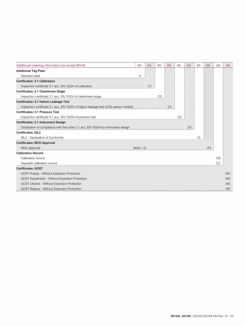
Additional ordering information for model 261AS XX XX XX XX XX XX XX XX XX XX
Additional Tag Plate
Stainless steel I1
Certificates: 3.1 Calibration
Inspection certificate 3.1 acc. EN 10204 of calibration C1
Certificates: 3.1 Cleanliness Stage
Inspection certificate 3.1 acc. EN 10204 of cleanliness stage C3
Certificates: 3.1 Helium Leakage Test
Inspection certificate 3.1 acc. EN 10204 of helium leakage test of the sensor module C4
Certificates: 3.1 Pressure Test
Inspection certificate 3.1 acc. EN 10204 of pressure test C5
Certificates: 2.1 Instrument Design
Declaration of compliance with the order 2.1 acc. EN 10204 for instrument design C6
Certificates: SIL2
SIL2 - Declaration of Conformity CL
Certificates: MVO Approval
MVO approval (Note: 12) CR
Calibration Record
Calibration record CB
Separate calibration record CC
Certificates: GOST
GOST Russia - Without Explosion Protection WC
GOST Kazakhstan - Without Explosion Protection WD
GOST Ukraine - Without Explosion Protection WE
GOST Belarus - Without Explosion Protection WF
Model 261GS for gauge pressure Model 261AS for absolute pressure
24 SS/261GS/AS-EN Rev. 07 | 261GS, 261AS
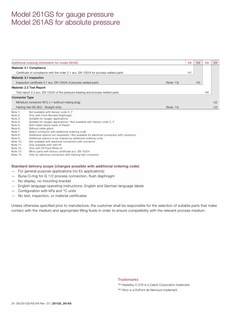
Additional ordering information for model 261AS XX XX XX XX
Material: 2.1 Compliance
Certificate of compliance with the order 2.1 acc. EN 10204 for process wetted parts H1
Material: 3.1 Inspection
Inspection certificate 3.1 acc. EN 10204 of process wetted parts (Note: 13) H3
Material: 2.2 Test Report
Test report 2.2 acc. EN 10204 of the pressure bearing and process wetted parts H4
Connector Type
Miniature connector M12 x 1 (without mating plug) U2
Harting Han 8D (8U) - Straight entry (Note: 14) U3
Note 1: Not available with Sensor code C, F Note 2: Only with Front Bonded Diaphragm Note 3: Suitable for oxygen applications Note 4: Suitable for oxygen applications / Not available with Sensor code C, F Note 5: With Cable Gland made of Plastic Note 6: Without cable gland Note 7: Select connector with additional ordering code Note 8: Additional options not requested / Not available for electrical connection with connector Note 9: Additional options to be ordered by additional ordering code Note 10: Not available with electrical connection with connector Note 11: Only available with inert fill Note 12: Only with Fill Fluid White oil Note 13: Minor parts with factory certificate acc. EN 10204 Note 14: Only for electrical connection with Harting Han connector
Standard delivery scope (changes possible with additional ordering code) — For general-purpose applications (no Ex applications) — Buna O-ring for G 1/2 process connection, flush diaphragm — No display, no mounting bracket — English-language operating instructions; English and German-language labels — Configuration with kPa and °C units — No test, inspection, or material certificates Unless otherwise specified prior to manufacture, the customer shall be responsible for the selection of suitable parts that make contact with the medium and appropriate filling fluids in order to ensure compatibility with the relevant process medium. Change from one to two columns
Trademarks
™ Hastelloy C-276 is a Cabot Corporation trademark
™ Viton is a DuPont de Nemours trademark
Change from two to one column

Notes
261GS, 261AS | SS/261GS/AS-EN Rev. 07 25
Notes

Notes
26 SS/261GS/AS-EN Rev. 07 | 261GS, 261AS
Notes

Notes
261GS, 261AS | SS/261GS/AS-EN Rev. 07 27
Notes

HMI HMI HMI HMI –––– Automação e Instrumentação, Lda.Automação e Instrumentação, Lda.Automação e Instrumentação, Lda.Automação e Instrumentação, Lda.
Rua dos 5 Caminhos, nº 570
4780-382 Santo Tirso
PORTUGAL
Web: www.hmi.pt
Tel. +351 252 850 501
Fax. +351 300 013 487
Email: [email protected]
Our offering:
Actuators and
Positioners
Analytical Instruments
Device Management,
Fieldbus and Wireless
Flow Measurement
Force Measurement
Level Measurement
Natural Gas
Measurement
Pressure Measurement
Recorders and
Controllers
Temperature
Measurement

Contact us
SS
/261
GS
/AS
-EN
Rev
. 07
10.2
014
ABB Ltd. Process Automation Howard Road, St. Neots Cambridgeshire, PE19 8EU UK Tel: +44 (0)1480 475321 Fax: +44 (0)1480 217948 ABB Inc. Process Automation 125 E. County Line Road Warminster PA 18974 USA Tel: +1 215 674 6000 Fax: +1 215 674 7183 ABB Automation Products GmbH Process Automation Schillerstr. 72 32425 Minden Germany Tel: +49 571 830-0 Fax: +49 571 830-1806 www.abb.com/pressure
Note We reserve the right to make technical changes or modify the contents of this document without prior notice. With regard to purchase orders, the agreed particulars shall prevail. ABB does not accept any responsibility whatsoever for potential errors or possible lack of information in this document. We reserve all rights in this document and in the subject matter and illustrations contained therein. Any reproduction, disclosure to third parties or utilization of its contents - in whole or in parts – is forbidden without prior written consent of ABB. Copyright© 2014 ABB All rights reserved 3KXP200005R1001
Sales
Service
Software