INSTITUTO DE MOBILIDADE TERRESTRE - fem.unicamp.brimt/INSTITUTO DE MOBILIDADE TERRESTRE.pdf ·...
233
PROGRAMA DE FORMAÇÃO OU CONSOLIDAÇÃO DOS INSTITUTOS NACIONAIS DE CIÊNCIA, TECNOLOGIA E INOVAÇÃO (INCT) PORTARIA DO MCT Nº 429 TRAINING PROGRAMME OR CONSOLIDATION OF NATIONAL INSTITUTES OF SCIENCE, TECHNOLOGY AND INNOVATION (INCT) MCT DECREE No. 429 REDE DE PESQUISA EM MOBILIDADE TERRESTRE AUTÔNOMA COM ÊNFASE EM DEFESA NACIONAL E SEGURANÇA PÚBLICA RESEARCH NETWORK IN AUTONOMOUS TERRESTRIAL MOBILITY WITH FOCUS ON NATIONAL DEFENSE AND PUBLIC SAFETY INSTITUTO DE MOBILIDADE TERRESTRE TERRESTRIAL MOBILITY INSTITUTE Prof. Dr. Jose Roberto de Franca Arruda – Unicamp/FEM – Coordenador Prof. Dr. Carlos Eduardo Cunasca – EPUSP – Vice-Coordenador Prof. Dr. Alberto Gaspar Guimarães – IME Prof. Dr. Alberto Luiz Serpa – Unicamp/FEM Ten Cel. Antonio Carlos Castañon Vieira – CTEx MSc. Arthur de Miranda Neto – Unicamp/FEM Prof. Dr. Claudio Garcia – EPUSP Prof. Dr. Clésio Luis Tozzi – Unicamp/FEEC Eng°. Danilo Habermann (Cap. QEM ) – EPUSP Prof. Dr. Douglas Eduardo Zampieri – Unicamp/FEM Maj. QEM. Geraldo Gurgel Filho – CTEx Prof. Dr. Janito Vaqueiro Ferreira – Unicamp/FEM Prof. Dr. Jorge Audrin Morgado de Góis – IME Prof. Dr. José Maria Campos dos Santos – Unicamp/FEM Prof. Dr. Juan Francisco Camino dos Santos – Unicamp/FEM Prof. Dr. Luciano Luporini Menegaldo – IME Prof. Dr. Pablo Siqueira Meirelles – Unicamp/FEM Prof. Dr. Paulo Fernando Ferreira Rosa – IME Maj. QEM. Paulo Roberto Rocha Aguiar – CTEx Maj. QEM. Victor Santoro Santiago – CTEx Setembro 2008
Transcript of INSTITUTO DE MOBILIDADE TERRESTRE - fem.unicamp.brimt/INSTITUTO DE MOBILIDADE TERRESTRE.pdf ·...
PROGRAMA DE FORMAÇÃO OU CONSOLIDAÇÃO DOS INSTITUTOS NACIONAIS DE CIÊNCIA, TECNOLOGIA E INOVAÇÃO (INCT)
PORTARIA DO MCT Nº 429
TRAINING PROGRAMME OR CONSOLIDATION OF NATIONAL INSTITUTES O F SCIENCE, TECHNOLOGY AND INNOVATION (INCT)
MCT DECREE No. 429
REDE DE PESQUISA EM MOBILIDADE TERRESTRE AUTÔNOMA C OM ÊNFASE EM DEFESA NACIONAL E SEGURANÇA PÚBLICA
RESEARCH NETWORK IN AUTONOMOUS TERRESTRIAL MOBILITY WITH FOCU S ON NATIONAL
DEFENSE AND PUBLIC SAFETY
INSTITUTO DE MOBILIDADE TERRESTRE TERRESTRIAL MOBILITY INSTITUTE
Prof. Dr. Jose Roberto de Franca Arruda – Unicamp/FEM – Coordenador
Prof. Dr. Carlos Eduardo Cunasca – EPUSP – Vice-Coordenador Prof. Dr. Alberto Gaspar Guimarães – IME
Prof. Dr. Alberto Luiz Serpa – Unicamp/FEM Ten Cel. Antonio Carlos Castañon Vieira – CTEx
MSc. Arthur de Miranda Neto – Unicamp/FEM Prof. Dr. Claudio Garcia – EPUSP
Prof. Dr. Clésio Luis Tozzi – Unicamp/FEEC Eng°. Danilo Habermann (Cap. QEM ) – EPUSP
Prof. Dr. Douglas Eduardo Zampieri – Unicamp/FEM Maj. QEM. Geraldo Gurgel Filho – CTEx
Prof. Dr. Janito Vaqueiro Ferreira – Unicamp/FEM Prof. Dr. Jorge Audrin Morgado de Góis – IME
Prof. Dr. José Maria Campos dos Santos – Unicamp/FEM Prof. Dr. Juan Francisco Camino dos Santos – Unicamp/FEM
Prof. Dr. Luciano Luporini Menegaldo – IME Prof. Dr. Pablo Siqueira Meirelles – Unicamp/FEM
Prof. Dr. Paulo Fernando Ferreira Rosa – IME Maj. QEM. Paulo Roberto Rocha Aguiar – CTEx
Maj. QEM. Victor Santoro Santiago – CTEx
Setembro 2008

RESUMO E OBJETIVOS
ii
Resumo A navegação (semi)-autônoma de veículos terrestres em ambientes considerados
desconhecidos tem sido impulsionada em quatro frentes com objetivos totalmente diferentes. A primeira delas, fora do foco deste projeto, diz respeito à exploração espacial, cujos artefatos, após a aterrissagem de seu transportador, realizam exploração em outros planetas e outros corpos celestes.
A segunda frente, com propósitos militares, tem tido apoio e incentivo da agência norte-americana conhecida como DARPA – Defense Advanced Research Projects, cuja principal missão é prover as forças armadas de tecnologia suficiente inovadora para manter sua superioridade tecnológica. Um dos objetivos expressos em sua visão de futuro está a transformação de um terço da frota de veículos militares em veículos autônomos para uso geral, inclusive em zonas urbanas densamente povoadas.
A terceira frente, que pode ser considerada como subdivisão da segunda acima citada, diz respeito à aplicação da robótica móvel na agricultura, em aplicações bastante diversificadas que vão desde a coleta de frutos ao plantio/colheita e aspergimento autônomos. Além do planejamento da trajetória, tais aplicações envolvem diferentes áreas, entre elas as chamadas redes CAM, navegação inercial e reconhecimento de padrões através de sensores terrestre e aéreos.
A quarta frente, apoiada pelas montadoras de veículos e seus fornecedores, tem o objetivo de criar sistemas de auxílio ao condutor, denominados Sistemas de Assistência ao Condutor (SAC), tornando seus produtos mais seguros e confortáveis em quaisquer condições de terreno ou climáticas. Além disso, graças a eletrônica embarcada e a utilização de sistemas auxiliares de visão, é possível interagir cada vez mais com o meio ambiente, tornando estradas e particularmente cidades mais seguras, tanto para motoristas como para pedestres (incluindo-se nesta categoria tanto adultos, cuja percepção de perigo é maior, como para crianças e idosos, mais susceptíveis a uma avaliação errônea do binômio espaço-tempo).
Tendo por panorama estes fatos, os pesquisadores das diferentes instituições superiores de ensino e pesquisa, que compõe o grupo de trabalho do presente projeto e interagindo com o CTEx – Centro Tecnológico do Exército, propõem formar um Instituto Nacional de Pesquisa em Mobilidade Terrestre, com o objetivo de potencializar suas capacidades individuais de pesquisa e de formação de recursos humanos e desenvolver uma plataforma robótica (semi)-autônoma, cuja navegação basear-se-á, principalmente, em visão (câmera e laser), em conjunto com sensores embarcados e técnicas para navegação autônoma. Tal plataforma se destinará à aplicações militares e civis.
De modo sumarizado, a navegação autônoma, entendida como a capacidade de um artefato realizar uma dada tarefa, deslocando-se de um ponto dado para outro previamente estabelecido, com liberdade ou não de estabelecer uma dada trajetória entre ambos, baseia-se em um conjunto de tarefas específicas, dentre as quais:
� Captar e processar as informações do ambiente e das condições do
terreno, ajustando (informando) os parâmetros de marcha do veículo;
� Utilizar técnicas de inteligência artificial para tomada de decisão
perante situações desconhecidas ou repetir os acertos de decisões
tomadas em situações já vivenciadas;
iii
� Atuar através de uma malha de controle robusto a falhas, redundante e
confiável;
� Processar os sinais de diferentes sensores através de uma rede de
comunicação em tempo real;
� Corrigir eventuais erros de trajetória, baseando-se em um conjunto de
sensores de localização inercial;
� Permitir, através de protocolos de comunicação adequados, que a
navegação inercial seja rastreada em tempo real.
Como se pode notar, as tarefas específicas acima listadas fazem parte da área de atuação das instituições acadêmicas envolvidas e seus docentes possuem comprovada experiência prévia sobre tais temas. Além disso, o projeto proposto não só está em consonância com a visão estratégica destas instituições, como também se alinha com as diretrizes das áreas de Defesa de nosso país, especialmente do Ministério da Defesa.
O projeto possui o mérito de envolver uma equipe multidisciplinar, envolvendo engenheiros mecânicos e engenheiros eletricistas em um tema atual, de valor tecnológico e estratégico. Para a consecução dos objetivos propostos as equipes deverão trabalhar com visão computacional, redes neurais, sensores laser, giroscópios, acelerômetros, plataformas inerciais, redes de comunicação, realidade virtual, eletrônica embarcada, processamento de imagens. Deste modo as linhas de pesquisa dos grupos de pesquisa envolvidos com conotação interdisciplinar e voltadas à mecatrônica serão modernizadas e fortalecidas. O impacto maior será nas seguintes linhas:
� Sistemas Mecânicos Ativos;
� Modelagem, Controle e Otimização de Sistemas;
� Sensores e Atuadores/ Fusão de Sensores;
� Navegação Inercial;
� Navegação Autônoma Guiada por Visão;
� Processamento de Imagens;
� Protocolos de Redes de Comunicação.
A principal proposta do presente projeto é a criação de uma plataforma robótica capaz de cumprir (semi)-autonomamente tarefas em ambientes desestruturados baseando-se em visão e sensores inerciais. Para tal será necessário o desenvolvimento de algoritmos computacionais a partir de sólidos conhecimentos de instrumentação e de processamento de sinais (incluindo visão), de controle robusto e de redes de comunicação. Docentes e pesquisadores poderão se aperfeiçoar em algoritmos e realidade virtual, caso prefiram a área de simulação ou em sensores e processamento, caso desejem fortalecer o conhecimento empírico. Em particular as áreas de visão, navegação inercial e controle serão as maiores beneficiárias de modernização e aperfeiçoamento.
iv
As métricas para mensurar objetivamente a melhoria dos programas de pós-graduação serão estabelecidas na primeira reunião após o início do projeto. De modo geral, o tema contribui para uma melhor formação interdisciplinar envolvendo simulação e experimentação, exige o oferecimento de novas disciplinas, obriga ter um melhor conhecimento do processamento e interpretação da fusão de sinais de diferentes sensores. A constante troca de informações e o trabalho conjunto entre as equipes certamente trará um incremento na produção técnico científica de todos os programas de pós-graduação envolvidos. A aquisição de equipamentos e a criação de novos aplicativos compartilhados entre os grupos ocasionarão uma modernização e uma maior produtividade.
O projeto se constitui em uma sólida base de desenvolvimento e modernização de veículos terrestre com fins duais – militar e/ou civil, utilizando uma tecnologia moderna, baseada em eletrônica embarcada, utilização de visão e sensores inerciais. Servirá também de plataforma para desenvolvimento de novos sensores ou para nacionalização de sensores considerados estratégicos.
Objetivos
O presente projeto, em consonância não só com a visão estratégica das Instituições envolvidas, mas também, alinhado com as diretrizes do Ministério da Ciência e Tecnologia e Ministério da Defesa, acima sumarizadas, visa em primeira linha:
� Capacitar os Laboratórios envolvidos na análise e desenvolvimento
teórico-experimental de sistemas robóticos (semi)-autônomos com
sensores de visão e de localização inercial.
� Capacitar pós-graduandos no domínio de ferramentas computacionais e
experimentais necessárias à descrição, entendimento e solução de
problemas envolvendo navegação robótica autônoma, baseada em
visão e sensores inerciais.
� Possibilitar a troca de informações científicas entre os grupos de
pesquisas.
� Incrementar a capacidade de divulgação acadêmico-científica dos
grupos de pesquisa através do desenvolvimento conjunto da pesquisa
em tela.
v
Abstract
The navigation (semi)-autonomous land vehicles in environments considered
unknown has been driven in four fronts with totally different goals. The first of them,
outside the focus of this project, is related to space exploration, whose artifacts, after
the landing of its carrier, held holding on other planets and other celestial bodies.
The second front, with military purposes, has had support and encouragement
of the U.S. agency known as DARPA - Defense Advanced Research Projects, whose
main mission is to provide the armed forces with technology innovative enough to
maintain its technological superiority. One of the goals expressed in its vision is the
transformation of one third of the fleet of military vehicles in autonomous vehicles for
general use, even in densely populated urban areas.
The third front, which can be regarded as the second subdivision of the
aforementioned concerns the application of mobile robotics in agriculture in very
diverse applications, ranging from collecting the fruits planting / harvesting and
spraying freelancers. In addition to planning the path, such applications involve
different areas, including the so-called CAM networks, inertial navigation and pattern
recognition through land and air sensors.
The fourth front, supported by the automotive industry, aims to create systems
to aid the driver, called the Driver Assistance System (DAS), making their products
more secure and comfortable in any conditions of land or climate. Also, thanks to
electronic on board and to the use of auxiliary systems of vision, it is possible to
interact with the environment, making roads and cities safer for both drivers and for
pedestrians (including both adults in this category, whose perception of danger is
greater, and for children and the elderly, more susceptible to a erroneous assessment
of binomial space-time).
Considering these facts, researchers from different high education and research
institutes are working in this group in close interaction with the CTEx - Technological
Center of the Brazilian Army. So, the group is proposing the creation of a National
Institute for Research in Mobility Ground, with the objective to enhance their
individual capacities for research and training of human resources and develop a
robotic platform (semi)-autonomous, whose navigation will be based mainly in vision
vi
(camera and laser), together with embedded sensors and techniques for autonomous
navigation. This platform would be used for civilian and military applications.
In few words, autonomous navigation, understood as the ability of an artifact
perform a given task, moving up from one point to another as previously established,
with freedom to establish whether or not a given path between them, is based on a set
of specific tasks, among them:
� Capturing and processing the information of the environment and the
conditions of the ground, adjusting (informing) the parameters of
movement of the vehicle;
� Using techniques of artificial intelligence for decision-making
situations to unknown or repeat the successes of decisions taken in
situations already experienced;
� Acting through a redundant and reliable mesh of robust control against
failures;
� Processing the signals of various sensors through a network of real-
time communications;
� Correcting any path mistakes, based on a set of sensors of inertial
location;
� Enabling that the inertial navigation is screened in real time, using
communication protocols.
As can be noticed, the specific tasks listed above are part of the knowledge
domain of the academic institutions involved in this project and their teachers have
proven experience on such issues. Moreover, the proposed project is not only in line
with the strategic vision of these institutions, as also aligns with the guidelines of the
areas of Defense of our country, especially the Ministry of Defense.
The project has the merit of involving a multidisciplinary team, involving
mechanical and electrician engineers in a current issue of technological and strategic
value. To achieve the objectives, the teams should work with computer vision, neural
networks, laser sensors, gyroscopes, accelerometers, inertial platforms,
communication networks, virtual reality, electronic board, process images. Thus the
groups’ research lines, specially those related to mechatronics, are to be upgraded and
strengthened. These lines will be more affected:
vii
� Mechanical Systems Assets; � Modeling, Control and Optimization Systems; � Sensors and Actuators / sensor fusion; � Inercial Navigation; � Autonomous Navigation Guided by Vision; � Image Processing; � Protocols of Communication
The main proposal of this project is the creation of a robotics platform capable
of meeting (semi-) independently tasks in non structured environments based on
vision and inertial sensors. This will require the development of computational
algorithms from solid knowledge of instrumentation and processing of signals
(including vision), robust control and communications networks. Professors and
researchers will be able to improve themselves in algorithms and virtual reality, if
they prefer the area of simulation or in sensors and processing, if they want to
strengthen the empirical knowledge. Particularly, the areas of vision, inertial
navigation and control will be the most benefited by modernization and improvement.
The metrics to measure objectively the improvement of post-graduate
programs will be established at the first meeting after the beginning of the project.
Generally, the main subject contributes to a better interdisciplinary training involving
simulation and testing, it also requires the offering of new disciplines and obliges a
better knowledge of processing and interpretation of the merger of signals from
different sensors. The constant exchange of information and joint work between the
teams certainly will bring an increase in the scientific production of all involved
postgraduate programs. The acquisition of equipment and the creation of new
applications shared by the groups will cause a modernization and greater productivity.
The project is in a solid basis for development and modernization of land vehicles
with dual purposes - military and / or civilian, using a modern technology, based on
electronic board, use of vision and inertial sensors. Also, it will serve as a platform for
development of new sensors or for nationalization of sensors considered strategic.
viii
Objectives This project, not only in line with the strategic vision of the institutions
involved, but also in line with directives from the Ministry of Science and Technology
and Ministry of Defense, summarized above, intends to:
� Train the laboratories involved in analysis and development of
theoretical and experimental robotic systems (semi)-autonomous with
sensors, vision and inertial location.
� Train post-graduating in the field of experimental and computational
tools necessary for the description, understanding and solving problems
involving robotics autonomous navigation, based on vision and inertial
sensors.
� Permit the exchange of scientific information among groups of
searchers.
� Increase the capacity of dissemination of academic and scientific
groups to search through the joint development of research on screen.

INFORMAÇÕES ADICIONAIS
RECIBO DE ENVIO DE FORMULÁRIOS ELETRÔNICOS
Número do protocoloSolicitanteCPF/CGCFormulário
9158979874219261Jose Roberto de Franca Arruda77820681853Formulário de Propostas Web (1.0.0)
O sistema de recepção de formulários eletrônicos do CNPq registra que, em 19/09/2008, às 16:02:46, o formulárioidentificado acima foi recebido e reconhecido no CNPq por meio do número de protocolo 9158979874219261
Acompanhe o andamento de sua solicitação no site do CNPq (http://www.cnpq.br) em 'PLATAFORMA CARLOSCHAGAS'.
Edital / Chamada Edital 15/2008 - Demanda Induzida - Faixa C
yPRnEsYtbUtfDIJgLjFr
Data: Thu, 25 Sep 2008 18:51:28 -0300
Para: [email protected]
Cópia: "Arthur de Miranda Neto" <[email protected]>, "Douglas Eduardo Za .....
Assunto: Edital 15/2008 - Indicação de novo vice-coordenador
Prezados senhores:
Fomos informados da desistência do Prof. Piqueira em função da inclusão de seu nome em dois projetos submetidos
ao Edital dos INCTs (Edital 15/2008), Processos 573583/2008-0 e 573912/2008-4.
Como o Prof. Piqueira optou por permanecer no projeto 573583/2008-0, ele não poderá mais ser o
vice-cooordenador do projeto de Instituto de Mobilidade Terrestre, que coordeno.
Para substituí-lo indico o Professor Carlos Eduardo Cugnasca, bolsista de Produtividade em Pesquisa do CNPq -
Nível 2, membro da equipe do projeto.
Atenciosamente,
José Roberto Arruda
--
Prof. Dr. José Roberto de França Arruda
Departamento de Mecânica Computacional
Faculdade de Engenharia Mecânica
Universidade Estadual de Campinas
Rua Mendeleyev,200
13083-860 Campinas, SP - Brasil
Phone: (55)(19) 3521-3194 Fax: (55)(19) 3289-3722
www.fem.unicamp.br/~lva
INSTITUTO DE MOBILIDADE TERRESTRE
TERRESTRIAL MOBILITY INSTITUTE
10
Justificativa
Introdução Auxiliar humanos a partir de sistemas automatizados, semi-autônomos e
autônomos é uma tendência decorrente da evolução tecnológica. Entretanto, no cumprimento de tarefas, por exemplo, para deslocamentos em área urbana, tem-se uma variável de grande impacto e importância, o ambiente. Mesmo que um ambiente seja previamente mapeado por um sistema de posicionamento global, a aleatoriedade e reposicionamentos constantes no decorrer do tempo, o descaracterizam parcial ou totalmente.
Atualmente, a pesquisa na área de navegação de autônoma e semi-autônoma tem motivado muitos pesquisadores de diferentes grupos devido ao desafio que representa. Digno de nota é o número de publicações nos últimos anos, incorporando os desenvolvimentos da área de telemática (MIRANDA NETO, 2007).
A partir de diretrizes governamentais dos EUA, há alguns anos, uma agência de pesquisa conhecida como DARPA (Defense Advanced Research Projects Agency) vem promovendo excelentes resultados na área de navegação autônoma. Esta agência é o principal órgão de pesquisa do Departamento de Defesa dos EUA e sua principal missão é manter a superioridade tecnológica do exército norte-americano prevenindo-se de uma surpresa tecnológica que possa prejudicar a segurança nacional. Neste objetivo, desde 2002 estimulam universidades, colégios e empresas de dentro e fora dos EUA a desenvolverem veículos autônomos, pois um dos objetivos do governo americano é transformar um terço de sua frota de veículos militares em autônomos até 2015.
Em conseqüência a isso, em 2004 e 2005 organizaram um desafio conhecido como Grand Challenge, Na primeira vez, em 2004, nenhuma das equipes conseguiu concluir com sucesso o percurso definido para a competição. Já em 2005 cinco equipes completaram o desafio, sendo a vencedora a equipe da Universidade de Stanford, Stanford Racing. Na ocasião do Grand Challenge 2005, o desafio foi a travessia do deserto de Mojave. A equipe vencedora completou a prova com uma velocidade média de 30.7 km/h.
O último desafio ocorreu em novembro de 2007. Conhecido como DARPA Urban Challenge, este desafio caracterizou-se por veículos autônomos que administraram suas missões em uma falsa área urbana, operação de extrema importância para o exército norte-americano. As etapas do desafio foram subdivididas em uma série de passos de qualificação, que conduziam para um evento final que aconteceu em Victorville, CA. Foram trinta e cinco equipes semifinalistas, onze finalistas e o primeiro lugar ficou com a equipe Tartan Racing, Pittsburgh, PA, o segundo lugar com a equipe Stanford Racing, Stanford, CA e o terceiro lugar com e equipe Victor Tango, Blacksburg, VA.
Durante o desafio urbano foi possível testar a habilidade dos veículos para operarem segura e efetivamente, interagindo com outros veículos dentro e ao redor de um ambiente urbano. O percurso teve uma distância total de aproximadamente 96 km, devendo ser completado num período de até 6 horas. Além do dever de seguir as leis de trânsito do local, as equipes tiveram como desafios: variações na qualidade do pavimento das estradas e vias, obstáculos como: meio-fios, barris de tráfico, hidrantes, pedras, equipamento de construção, fios de alta tensão, além dos outros obstáculos estacionários encontrados num ambiente urbano. Uma dificuldade adicional foi a
11
possibilidade de bloqueios serem erguidos durante o curso do evento, além das interferências com o sinal do sensor GPS (Global Position System) causadas por árvores e edifícios ao longo da rota.
É possível notar o quanto é audacioso o plano do Departamento de Defesa dos EUA até 2015, porém num período de aproximadamente cinco anos, os resultados obtidos nos desafios Grand Challenge e Urban Challenge apresentaram um grande avanço nesta direção.
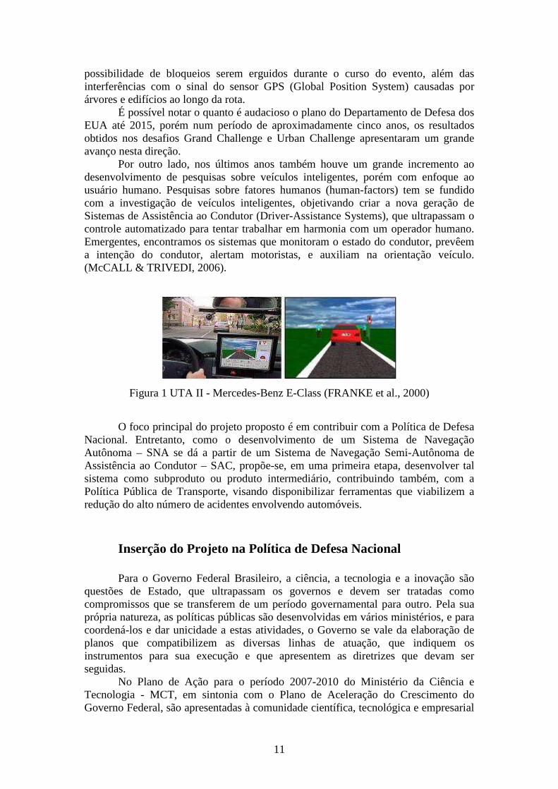
Por outro lado, nos últimos anos também houve um grande incremento ao desenvolvimento de pesquisas sobre veículos inteligentes, porém com enfoque ao usuário humano. Pesquisas sobre fatores humanos (human-factors) tem se fundido com a investigação de veículos inteligentes, objetivando criar a nova geração de Sistemas de Assistência ao Condutor (Driver-Assistance Systems), que ultrapassam o controle automatizado para tentar trabalhar em harmonia com um operador humano. Emergentes, encontramos os sistemas que monitoram o estado do condutor, prevêem a intenção do condutor, alertam motoristas, e auxiliam na orientação veículo. (McCALL & TRIVEDI, 2006).
Figura 1 UTA II - Mercedes-Benz E-Class (FRANKE et al., 2000)
O foco principal do projeto proposto é em contribuir com a Política de Defesa
Nacional. Entretanto, como o desenvolvimento de um Sistema de Navegação Autônoma – SNA se dá a partir de um Sistema de Navegação Semi-Autônoma de Assistência ao Condutor – SAC, propõe-se, em uma primeira etapa, desenvolver tal sistema como subproduto ou produto intermediário, contribuindo também, com a Política Pública de Transporte, visando disponibilizar ferramentas que viabilizem a redução do alto número de acidentes envolvendo automóveis.
Inserção do Projeto na Política de Defesa Nacional Para o Governo Federal Brasileiro, a ciência, a tecnologia e a inovação são
questões de Estado, que ultrapassam os governos e devem ser tratadas como compromissos que se transferem de um período governamental para outro. Pela sua própria natureza, as políticas públicas são desenvolvidas em vários ministérios, e para coordená-los e dar unicidade a estas atividades, o Governo se vale da elaboração de planos que compatibilizem as diversas linhas de atuação, que indiquem os instrumentos para sua execução e que apresentem as diretrizes que devam ser seguidas.
No Plano de Ação para o período 2007-2010 do Ministério da Ciência e Tecnologia - MCT, em sintonia com o Plano de Aceleração do Crescimento do Governo Federal, são apresentadas à comunidade científica, tecnológica e empresarial
12
e à sociedade brasileira as seguintes metas: consolidação da infra-estrutura de pesquisa científica e tecnológica do País, por meio do fomento a projetos individuais e coletivos, incluindo as redes formadas por universidades, centros de pesquisa e institutos tecnológicos; aperfeiçoamento dos mecanismos e instrumentos de fomento ao desenvolvimento da C, T&I, por meio da ampliação do aporte de recursos aos programas atuais e da criação de novos programas voltados para o atendimento da crescente demanda por pesquisa e desenvolvimento das diversas áreas do conhecimento; expansão da Rede Nacional de Ensino e Pesquisa (RNP), para interligar em alta velocidade as entidades do Sistema Nacional de Educação, Ciência, Tecnologia e Inovação; consolidação das unidades de pesquisa do MCT, na condição de laboratórios nacionais ou núcleos coordenadores de redes temáticas em áreas estratégicas para o desenvolvimento autônomo do País, estimulando a associação dessas com as unidades estaduais, ou municipais, para o desenvolvimento das atividades de P, D&I.
Além disso, pretende-se também, promover a pesquisa e o desenvolvimento de tecnologias focadas nas prioridades da Política Nacional de Defesa e de interesse da segurança pública, por meio do apoio à infra-estrutura de pesquisa das instituições científicas e tecnológicas – ICT’s nessas áreas; à capacitação de recursos humanos; e à inovação em empresas nacionais. Serão apoiadas ainda, parcerias entre ICT’s e órgãos públicos para a formulação, a implementação e a avaliação de políticas de segurança pública e de combate à criminalidade.
A ciência, a tecnologia e a inovação são, no cenário mundial contemporâneo, instrumentos fundamentais para o desenvolvimento, o crescimento econômico, a geração de emprego e renda e a democratização de oportunidades. O trabalho de técnicos, cientistas, pesquisadores e acadêmicos e o engajamento das empresas são fatores determinantes para a consolidação de um modelo de desenvolvimento sustentável, capaz de atender às justas demandas sociais dos brasileiros e ao permanente fortalecimento da soberania nacional. Novamente, esta é uma questão de Estado, que ultrapassa os governos.
Destaca-se ainda, o próprio edital ao qual este projeto se submete, cujos temas prioritários têm relação direta com as áreas estratégicas do plano de ação em C,T&I, incluindo-se aí a Defesa Nacional. No Brasil, encontramos diretrizes de incentivo para pesquisa cientifica na área de Defesa Nacional. No que se refere à área de Ciência, Tecnologia e Inovação, no sítio do Ministério da Defesa, diz que o ministério tem a missão de viabilizar soluções científico-tecnológicas e inovações para a satisfação das necessidades do país atinentes à defesa e ao desenvolvimento nacional. Desta forma, criou-se um delineamento de Áreas e Tecnologias de Interesse da Defesa Nacional, sendo o detalhamento dessas Áreas Estratégicas em um espaço delimitado por três eixos, capazes de criar vetores interagentes e coordenados, denominados de Tecnologias de Interesse da Defesa Nacional:
� Eixo da Defesa - contempla as especificações e os requisitos militares
da Defesa Nacional a serem satisfeitos por Sistemas de Armas.
Relaciona-se primordialmente às Expressões Política e Militar do
Poder Nacional.
13
� Eixo da Ciência e Tecnologia - contempla as Áreas Tecnológicas
Estratégicas necessárias para atender às especificações e aos requisitos
definidos para os Sistemas da Defesa Nacional. Relaciona-se
primordialmente à Expressão Científica e Tecnológica do Poder
Nacional.
� Eixo da Indústria - contempla as capacidades inovadoras e
características industriais próprias para satisfação das especificações e
dos requisitos estabelecidos para os Sistemas da Defesa Nacional.
Relaciona-se primordialmente às Expressões Econômica e Psicossocial
do Poder Nacional.
Dentre as tecnologias de interesse nacional definidas pelo Ministério da
Defesa, destacam-se: Fusão de Dados, Inteligência de Máquinas & Robótica e Integração de Sistemas.
Outras iniciativas deste ministério foram os editais para o desenvolvimento de pesquisas e projetos dentro do programa Pró-Defesa (Programa de Apoio ao Ensino e à Pesquisa Científica e Tecnológica em Defesa Nacional). Neste caso, tratou-se de uma parceria entre o Ministério da Defesa e a Capes (Fundação Coordenação de Aperfeiçoamento de Pessoal de Nível Superior). Seu objetivo é financiar e estimular a produção de pesquisas científicas e tecnológicas e a formação de pós-graduados na área de Defesa Nacional.
Com o objetivo de reduzir o hiato tecnológico em relação aos exércitos mais modernos e à dependência bélica do exterior, alinhadas com a Política de Defesa Nacional e com as políticas e diretrizes emanadas do Ministério da Defesa, na Diretriz Geral do Comandante do Exército Brasileiro, a Força Terrestre Brasileira - F Ter, como força armada, deverá continuar atuando em perfeita consonância com a Marinha do Brasil e com a Força Aérea Brasileira, tanto em seu planejamento estratégico de preparo como no seu emprego.
Está na diretriz que o Exército Brasileiro continuará a busca do efetivo domínio do conhecimento científico tecnológico e da capacidade de inovação, a fim de dotar a força terrestre com sistemas modernos produzidos, prioritariamente, pela indústria de defesa nacional, cuja recuperação continuará como objetivo a ser perseguido.
Progressivamente, tecnologias mais avançadas serão agregadas, privilegiando sempre a pesquisa aplicada e os projetos de tecnologia dual. Dentre os projetos em curso, diz que deverão ser considerados como concentradores dos esforços tecnológicos o da Família de Blindados Sobre Rodas, o do Sistema de Defesa Antiaérea e o do Sistema de Comando e Controle em Combate. Na mesma diretriz também se apresenta a continuidade do trabalho iniciado por comandos anteriores, tendo como meta, ampliar o intercâmbio entre as instituições civis e militares nas áreas do ensino, da pesquisa científica e da cultura, capacitação dos recursos humanos para as áreas de ciência e tecnologia, baseada em um judicioso estudo das necessidades institucionais, de modo a proporcionar o máximo de permanência do profissional no projeto ou atividade para que foi habilitado.
14
Do último parágrafo, enfatizam-se os acordos já realizados entre o Exército Brasileiro e a Universidade Estadual de Campinas (UNICAMP). Em 2004, em reunião entre o comandante do Exército Brasileiro e o reitor da Unicamp, sobre a preparação de um laboratório dentro da universidade. Atualmente, subordinado ao Centro Tecnológico do Exército - CTEx, um escritório de prospecção já foi implantado na UNICAMP. Em 2006, cerimônia realizada no Gabinete do Reitor para assinatura de um convênio entre a UNICAMP e o Comando do Exército Brasileiro, através do seu Departamento de Ciência e Tecnologia. Em 2007, assinatura de dois convênios com o CTEx. Esta parceria, de prestação de serviço científico e tecnológico na área de desenvolvimento de plano focal de InGaAs e de bolômetros de silício, envolverá recursos da ordem de R$ 1,2 milhão, financiados pelo Ministério da Ciência e Tecnologia - MTC e Financiadora de Estudos e Projetos - FINEP.
Visando mobilidade terrestre e assistência ao condutor, subordinado à Diretoria de Fabricação, que por sua vez está subordinada à Diretoria de Ciência e Tecnologia - DCT do Exército Brasileiro, encontra-se em São Paulo, o Arsenal de Guerra de São Paulo - AGSP. Sua missão é contribuir com a operacionalidade da F Ter por meio da fabricação e recuperação de Material de Emprego Militar - MEM. Dentre estas atividades, destaca-se a missão de implantar e manter o Grupo de Blindados e Veículos Militares no âmbito do DCT, com a finalidade de apoiar os projetos de desenvolvimento experimental de sistemas militares realizados pelo CTEx, através do fomento as atividades de pesquisa aplicada na área de blindados e veículos militares e da capacitação de recursos humanos utilizados nos projetos. Em sua visão de futuro, deseja ser um centro de excelência em MEM, particularmente na área de mobilidade terrestre.
Como forças auxiliares e reserva do Exército Brasileiro que integram o Sistema de Segurança Pública e Defesa Social brasileiro, nos estados, temos as polícias militares, que são forças de segurança pública das unidades federativas que têm por função primordial a polícia ostensiva e a preservação da ordem pública nos Estados brasileiros e no Distrito Federal - artigo 144 da Constituição Federal de 1988. Subordinam-se, juntamente com as polícias civis, aos Governadores dos Estados, do Distrito Federal e dos Territórios - art. 144 § 6º da Constituição Federal de 1988. Outro importante aspecto no desenvolvimento de pesquisas científico-tecnológicas no Brasil, principalmente quando há proveito militar, se refere à aquisição de tecnologias e equipamentos originados de outros países. Centrado em privilegiar a indústria nacional, em setembro de 2007, o Governo Federal anunciou a elaboração do Plano Estratégico Nacional de Defesa. Previsto para ser lançado em setembro de 2008, visa apresentar uma política de defesa nacional aliada a uma estratégia de longo prazo, para reativar a indústria de material de defesa no País e reaparelhar as Forças Armadas. Além disso, no início deste ano de 2008, cooperação em estratégia militar marca a pauta das reuniões com os titulares da Defesa, Nelson Jobim (Brasil), Hervé Morin (França), Anatoli Serdiukov (Rússia) e Nilda Garré (Argentina). Em janeiro de 2008, Brasil e França fecharam uma aliança estratégica para o setor de Defesa.
15
Viaturas Militares em Área Urbana e Trânsito no Brasil Seja em missões realizadas pelas forças armadas ou forças auxiliares, onde
pode haver grande hostilidade inimiga, por exemplo: em incursões em terrenos desconhecidos ou de predominância inimiga, os sistemas autônomos ou semi-autônomos podem contribuir para o sucesso destas missões, inclusive poupando vidas.
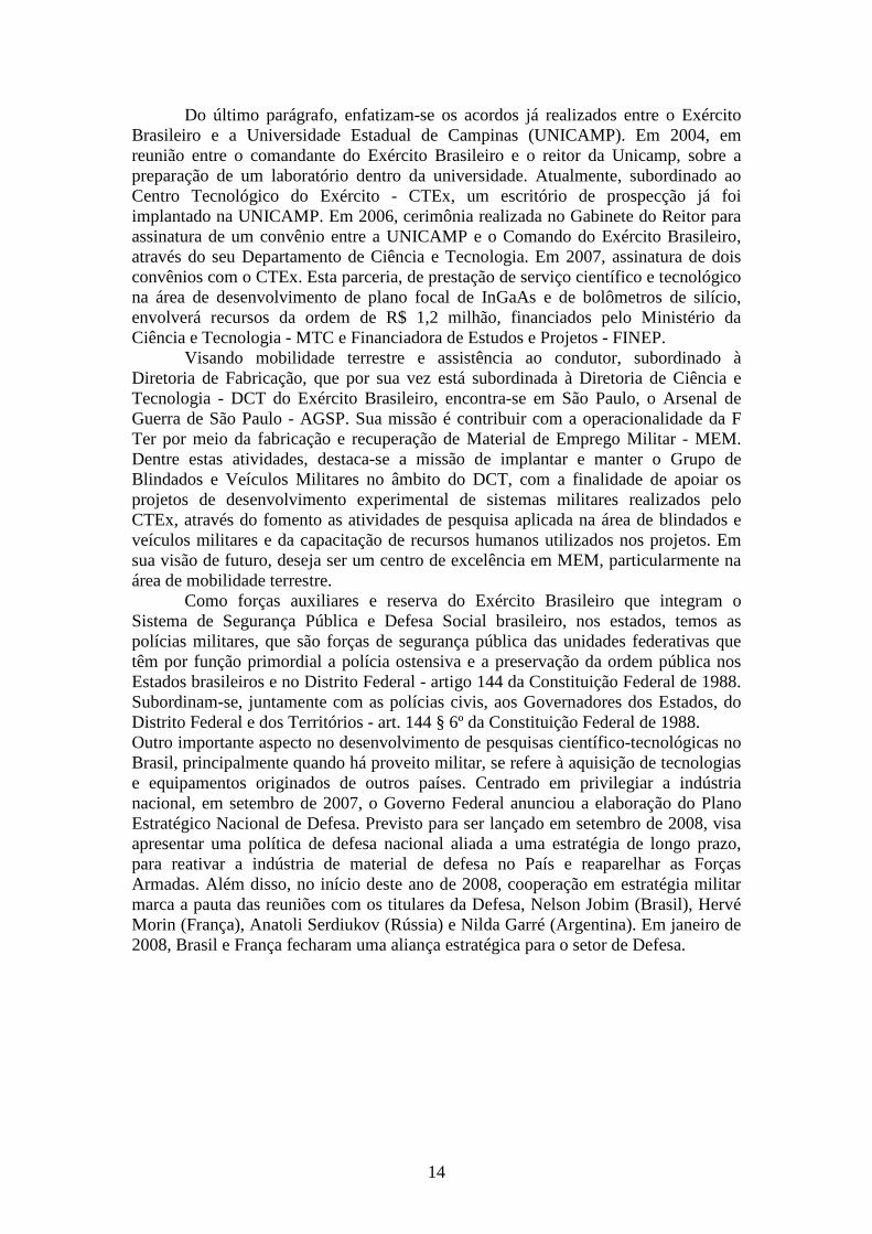
Principalmente no contexto das Forças Armadas, ao observarmos os conflitos atuais, nota-se o crescente emprego de viaturas militares em área urbana. Cresce também a complexidade da operação militar, pois em muitos casos, estas áreas apresentam difícil acesso e são muito populosas. Portanto, conclui-se que sob o condutor recai grande responsabilidade. Como exemplo, na figura 2 as operações militares em área urbana.
Figura 2 – Operação militar em área urbana. Em destaque, operações do Exército
Brasileiro no Haiti e com a Polícia Militar no RJ.
Além dos acordos entre o Exército Brasileiro e a UNICAMP citados anteriormente, a imprensa escrita divulgou que esforços vêm sendo realizados para viabilizar o desenvolvimento de pesquisa aplicada à segurança pública. Em dezembro de 2007, uma Viatura Blindada Tática Leve - VBTL foi apresentado à direção da FAPERJ pelo chefe do CTEx, General-de-Divisão Aléssio Ribeiro Souto. Capaz de resistir a tiros de fuzil, com design mais racional, refrigerado e mais confortável, poderá vir a patrulhar áreas urbanas e ser usado no deslocamento de detidos.
A Nova Família de Blindados Média de Rodas - FBMR é outro projeto sob a direção do Exército Brasileiro. O Programa Viatura Blindada de Transporte de Pessoal – Média de Rodas (VBTP-MR) será desenvolvido pela empresa FIAT Automóveis S.A, holding do Grupo FIAT no Brasil e representando a Divisão IVECO.
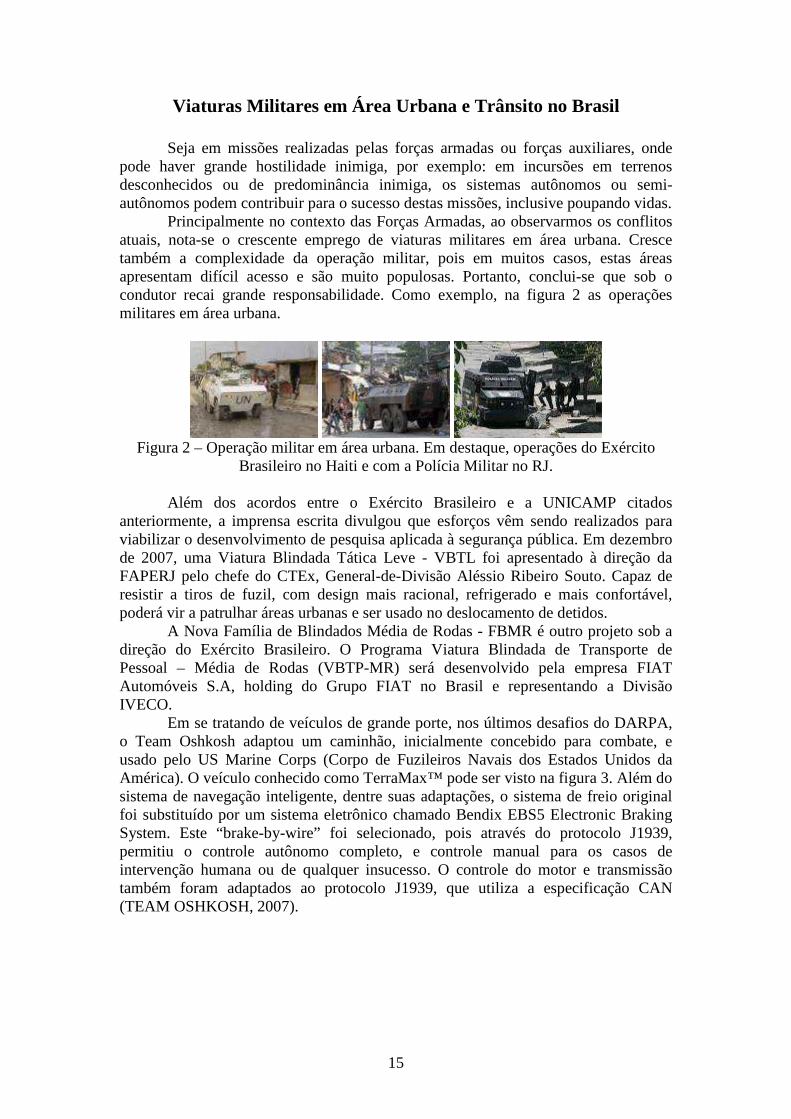
Em se tratando de veículos de grande porte, nos últimos desafios do DARPA, o Team Oshkosh adaptou um caminhão, inicialmente concebido para combate, e usado pelo US Marine Corps (Corpo de Fuzileiros Navais dos Estados Unidos da América). O veículo conhecido como TerraMax™ pode ser visto na figura 3. Além do sistema de navegação inteligente, dentre suas adaptações, o sistema de freio original foi substituído por um sistema eletrônico chamado Bendix EBS5 Electronic Braking System. Este “brake-by-wire” foi selecionado, pois através do protocolo J1939, permitiu o controle autônomo completo, e controle manual para os casos de intervenção humana ou de qualquer insucesso. O controle do motor e transmissão também foram adaptados ao protocolo J1939, que utiliza a especificação CAN (TEAM OSHKOSH, 2007).
16
Figura 3 – TerraMax™, caminhão construído por Team Oshkosh para o 2007
DARPA Urban Challenge (TEAM OSHKOSH, 2007). Para os cidadãos comuns, os Sistemas de Assistência ao Condutor - SAC,
também possuem grande importância. Por exemplo, devido as mais complexas situações de tráfego, frações de segundo podem ser decisivas para se evitar acidentes de trânsito, onde um dos principais fatores é o tempo de reação humano, além do cansaço, distrações e da possibilidade de se adormecer ao volante. Pesquisas indicam que cerca de 60% das colisões traseiras e quase um terço das colisões frontais poderiam ter sido evitadas, caso o condutor tivesse reagido apenas meio segundo antes.
Segundo um estudo divulgado pela Universidade Estadual Paulista - UNESP, no Brasil cerca de 40 mil pessoas perdem a vida anualmente em acidentes de transito. Os números brasileiros estão na frente de qualquer país do mundo. Em 2007, Segundo a Polícia Militar Paulista, durante todo o período do carnaval, foram 1.151 acidentes. Nos últimos dez anos, 327.469 pessoas perderam suas vidas em acidentes de trânsito no Brasil. Os atropelamentos e colisões respondem por 4% dos óbitos do país - de cada 25 brasileiros que morrem, um perde a vida no trânsito. Segundo o Ministério da Saúde, são 98 mortes por dia, 35 mil por ano, números comparáveis, por exemplo, aos 37 mil óbitos anuais registrados na guerra do Iraque (RENAEST, 2007).
Responsável por mais de 90% dos acidentes registrados, tem-se o erro humano. Geralmente vinculados a velocidade excessiva; a distância insuficiente em relação ao veiculo dianteiro; desrespeito à sinalização (UNESP, 2007).
O mesmo estudo apresenta que para que um condutor responda adequadamente a determinado estimulo, é necessário que esteja em "alerta", caso contrário poderá causar um acidente. Este estado de "alerta" é afetado por muitos fatores, fazendo com que as pessoas respondam com maior ou menor rapidez em situações de emergências. O intervalo de tempo entre o reconhecimento de uma situação perigosa e a ação de resposta a esta situação é chamado de tempo de reação, e depende da condição física e do estado emocional do indivíduo. O tempo médio de reação de uma pessoa jovem em bom estado de saúde é de aproximadamente 0,75 segundos. Este é praticamente o tempo que o cérebro necessita para processar as informações que está recebendo e definir uma ação. Fatores que influenciam o tempo de reação:
� Definitivos: idade, deficiência física (visão, audição, paralisias, etc);
� Temporários: enfermidades passageiras (resfriado comum, dor de
cabeça, etc), álcool, drogas, medicamentos, estado emocional;
No mesmo estudo, apresenta-se que muitos indivíduos ao conduzirem seus veículos criam condições ideais e irreversíveis para que o acidente ocorra. Isto normalmente ocorre em função da completa ignorância em relação aos fatores
17
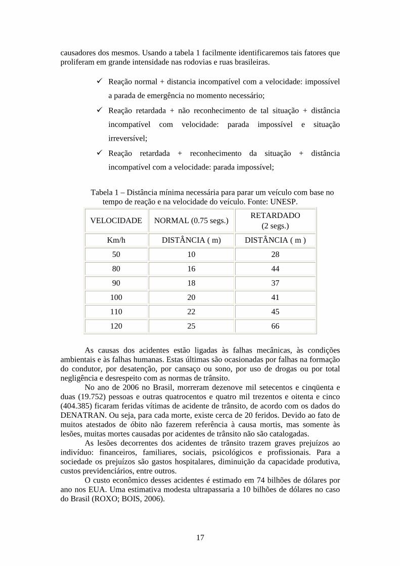
causadores dos mesmos. Usando a tabela 1 facilmente identificaremos tais fatores que proliferam em grande intensidade nas rodovias e ruas brasileiras.
� Reação normal + distancia incompatível com a velocidade: impossível
a parada de emergência no momento necessário;
� Reação retardada + não reconhecimento de tal situação + distância
incompatível com velocidade: parada impossível e situação
irreversível;
� Reação retardada + reconhecimento da situação + distância
incompatível com a velocidade: parada impossível;
Tabela 1 – Distância mínima necessária para parar um veículo com base no
tempo de reação e na velocidade do veículo. Fonte: UNESP.
VELOCIDADE NORMAL (0.75 segs.) RETARDADO
(2 segs.)
Km/h DISTÂNCIA ( m) DISTÂNCIA ( m )
50 10 28
80 16 44
90 18 37
100 20 41
110 22 45
120 25 66
As causas dos acidentes estão ligadas às falhas mecânicas, às condições
ambientais e às falhas humanas. Estas últimas são ocasionadas por falhas na formação do condutor, por desatenção, por cansaço ou sono, por uso de drogas ou por total negligência e desrespeito com as normas de trânsito.
No ano de 2006 no Brasil, morreram dezenove mil setecentos e cinqüenta e duas (19.752) pessoas e outras quatrocentos e quatro mil trezentos e oitenta e cinco (404.385) ficaram feridas vítimas de acidente de trânsito, de acordo com os dados do DENATRAN. Ou seja, para cada morte, existe cerca de 20 feridos. Devido ao fato de muitos atestados de óbito não fazerem referência à causa mortis, mas somente às lesões, muitas mortes causadas por acidentes de trânsito não são catalogadas.
As lesões decorrentes dos acidentes de trânsito trazem graves prejuízos ao indivíduo: financeiros, familiares, sociais, psicológicos e profissionais. Para a sociedade os prejuízos são gastos hospitalares, diminuição da capacidade produtiva, custos previdenciários, entre outros.
O custo econômico desses acidentes é estimado em 74 bilhões de dólares por ano nos EUA. Uma estimativa modesta ultrapassaria a 10 bilhões de dólares no caso do Brasil (ROXO; BOIS, 2006).
18
De acordo com Evans (1991), 2% dos acidentes de trânsito observados em uma pesquisa realizada no Reino Unido foram causados exclusivamente pelas condições ambientais da rodovia, 2% estão ligados somente com as falhas do veículo e 65% são exclusivos de falhas humanas. Além disso, constatou-se que 95% dos acidentes têm o fator falha humana como causa, quer como fato isolado, quer associado a outros fatores.
A falta de atenção foi apontada como causa de 76,6% dos acidentes com veículos pesados na rodovia BR-153 em um estudo epidemiológico sobre acidentes de trânsitos (SANTOS, (1999) apud MELIONE, (2006)).
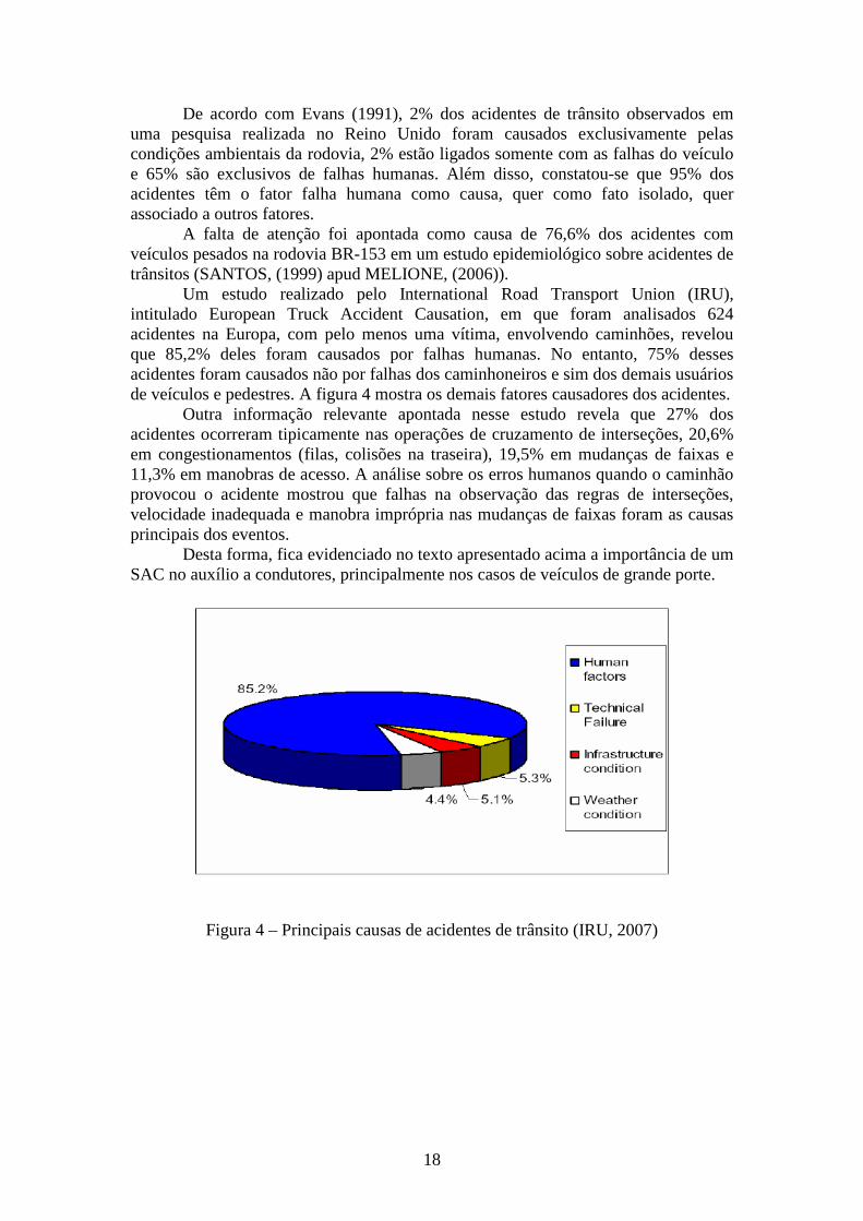
Um estudo realizado pelo International Road Transport Union (IRU), intitulado European Truck Accident Causation, em que foram analisados 624 acidentes na Europa, com pelo menos uma vítima, envolvendo caminhões, revelou que 85,2% deles foram causados por falhas humanas. No entanto, 75% desses acidentes foram causados não por falhas dos caminhoneiros e sim dos demais usuários de veículos e pedestres. A figura 4 mostra os demais fatores causadores dos acidentes.
Outra informação relevante apontada nesse estudo revela que 27% dos acidentes ocorreram tipicamente nas operações de cruzamento de interseções, 20,6% em congestionamentos (filas, colisões na traseira), 19,5% em mudanças de faixas e 11,3% em manobras de acesso. A análise sobre os erros humanos quando o caminhão provocou o acidente mostrou que falhas na observação das regras de interseções, velocidade inadequada e manobra imprópria nas mudanças de faixas foram as causas principais dos eventos.
Desta forma, fica evidenciado no texto apresentado acima a importância de um SAC no auxílio a condutores, principalmente nos casos de veículos de grande porte.
Figura 4 – Principais causas de acidentes de trânsito (IRU, 2007)
19
Fundamentação Teórica Metodologia
Na introdução desta proposta ressaltou-se a importância dos sistemas de
navegação autônomos propostos nos desafios do DARPA. Neste item pretende-se enfatizar a importância da pesquisa aplicada, inicialmente, a um SAC - Sistema de Navegação Semi-Autônoma, como produto intermediário de projeto de um veículo autônomo.
Em relação a navegação autônoma e semi-autônoma, destaca-se que para muitas ocasiões não será possível à dispensa do ser humano, principalmente em operações militares, o que leva a sistemas autônomos e semi-autônomos a terem a mesma relevância.
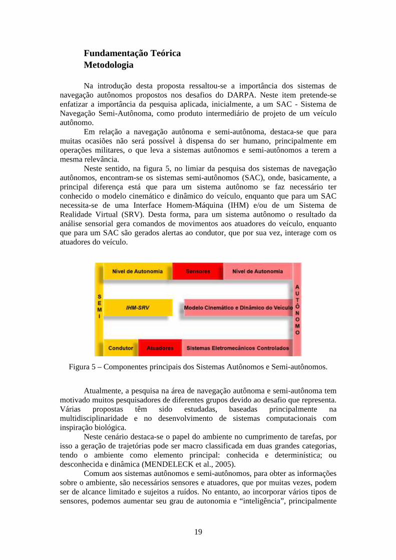
Neste sentido, na figura 5, no limiar da pesquisa dos sistemas de navegação autônomos, encontram-se os sistemas semi-autônomos (SAC), onde, basicamente, a principal diferença está que para um sistema autônomo se faz necessário ter conhecido o modelo cinemático e dinâmico do veículo, enquanto que para um SAC necessita-se de uma Interface Homem-Máquina (IHM) e/ou de um Sistema de Realidade Virtual (SRV). Desta forma, para um sistema autônomo o resultado da análise sensorial gera comandos de movimentos aos atuadores do veículo, enquanto que para um SAC são gerados alertas ao condutor, que por sua vez, interage com os atuadores do veículo.
Figura 5 – Componentes principais dos Sistemas Autônomos e Semi-autônomos.
Atualmente, a pesquisa na área de navegação autônoma e semi-autônoma tem
motivado muitos pesquisadores de diferentes grupos devido ao desafio que representa. Várias propostas têm sido estudadas, baseadas principalmente na multidisciplinaridade e no desenvolvimento de sistemas computacionais com inspiração biológica.
Neste cenário destaca-se o papel do ambiente no cumprimento de tarefas, por isso a geração de trajetórias pode ser macro classificada em duas grandes categorias, tendo o ambiente como elemento principal: conhecida e determinística; ou desconhecida e dinâmica (MENDELECK et al., 2005).
Comum aos sistemas autônomos e semi-autônomos, para obter as informações sobre o ambiente, são necessários sensores e atuadores, que por muitas vezes, podem ser de alcance limitado e sujeitos a ruídos. No entanto, ao incorporar vários tipos de sensores, podemos aumentar seu grau de autonomia e “inteligência”, principalmente
20
em relação à navegação em ambientes desconhecidos. Em contrapartida, o tipo e a quantidade de sensores determinam o volume de dados para o processamento e composição da “imagem” do ambiente, impondo na maioria dos casos, um alto custo computacional. Este custo, por muitas vezes, pode inviabilizar projetos que utilizem equipamentos de pouca capacidade e/ou de aplicações de tempo real.
De aplicação comum para as decisões de sistemas não-determinísticos encontram-se os sistemas computacionais com inspiração biológica: Redes Neurais Artificiais e Sistemas Classificadores & Algoritmos Genéticos. No intuito de apresentar algumas características comuns entre sistemas computacionais e biológicos, a seguir trançamos um paralelo ao comportamento biológico humano observando a organização do sistema nervoso, do sistema de visão e o compartilhamento de conhecimento.
Independente do tipo de ambiente, para a navegação de humanos, o sistema nervoso em conjunto com o sistema endócrino desempenha funções de controle do organismo. Este sistema recebe milhares de informações dos diferentes órgãos sensoriais, e seu papel é integrá-las a fim de determinar respostas a serem executadas. Sua composição tem origem nas experiências sensoriais adquiridas através dos receptores sensoriais, podendo ser provenientes das experiências auditivas, visuais e vinculadas ao tato (GUYTON, 1973).
Uma das funções principais do sistema nervoso é atingir respostas ideais. Muitas das informações adquiridas pelos sensores são desprezadas após passarem pelo processamento de informações do cérebro, e isso pode ser justificado se considerarmos o fato de que humanos podem desempenhar diversas atividades simultaneamente. Como exemplo, durante a condução de um veículo, uma pessoa pode desenvolver outras atividades, como conversar, pensar em outras coisas diferentes daquela primordial, ou mesmo ignorar o fato que sua pele está em contato com suas vestimentas. Especialmente aplicado à visão humana, em determinado momento, o foco da visão de uma pessoa pode estar centrado em uma área específica do ambiente, por exemplo, na estrada por onde navega, no entanto, as outras áreas deste ambiente não estão sendo ignoradas, isto é, para estas sub-imagens do ambiente estará sendo delegado um segundo plano.
Para realizar o armazenamento das informações, seres humanos possuem o córtex cerebral e a medula espinhal. Este processo de armazenamento pode ser chamado de memória. As informações a serem armazenadas trafegam através das sinapses, que possuem propriedades muito diversas, tais como, transmitir um sinal de um neurônio para outro. A partir do momento que as recordações tenham sido armazenadas no sistema nervoso, se tornarão parte do mecanismo de elaboração, ou seja, poderão ser utilizadas para atividades motoras posteriores. Tais recordações serão comparadas futuramente a novas experiências, a fim de auxiliar na seleção de novas informações (GUYTON, 1973).
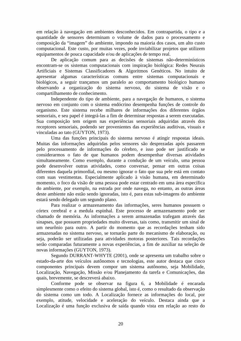
Segundo DURRANT-WHYTE (2001), onde se apresenta um trabalho sobre o estado-da-arte dos veículos autônomos e tecnologias, este autor destaca que cinco componentes principais devem compor um sistema autônomo, seja Mobilidade, Localização, Navegação, Missão e/ou Planejamento da tarefa e Comunicações, das quais, brevemente, se descreverá abaixo.
Conforme pode se observar na figura 6, a Mobilidade é encarada simplesmente como o efeito do sistema global, isto é, como o resultado da observação do sistema como um todo. A Localização fornece as informações do local, por exemplo, atitude, velocidade e aceleração do veículo. Destaca ainda que a Localização é uma função exclusiva de saída quando vista em relação ao resto do
21
sistema. Isto significa que o desenvolvimento da capacidade Localização pode por muitas vezes proceder de forma independente dos outros componentes do sistema.
A Navegação está preocupada com a aquisição e resposta às informações do ambiente externo. A função de Navegação recebe como entrada o resultado da observação dos sensores no ambiente operacional. Esta observação de muita importância, pois permite criar uma representação interna do ambiente, que pode ser utilizados posteriormente durante a execução de uma missão.
Missão e/ou Planejamento da Tarefa é responsável por gerar as trajetórias, comportamentos e/ou pontos de passagem para o sistema como um todo. Ela não tem nenhuma ligação direta com qualquer controlador de entrada ou saída sensorial. No entanto, ele deve ter uma clara compreensão dos mesmos, em conjugação com os mapas lidos antes missão e possíveis objetivos a serem cumpridos, a fim de produzir comandos adequados de navegação.
A Comunicação prevê a ligação entre o veículo e todos os possíveis elementos do sistema global, incluindo outros veículos e/ou operadores. Não há qualquer razão para supor que um sistema autônomo ou (Semi)-autônomo não deve compartilhar suas informações com outros sistemas de comunicação, a não ser que a missão exija tal feito.
Figura 6 – Relação entre os diferentes componentes funcionais de um sistema de navegação autônomo (DURRANT-WHYTE, 2001).
Vale ressaltar que apesar da elevada importância da missão a ser cumprida por
um sistema autônomo, isto é, devido ao poder de influência das informações da missão sob o sistema global, tal fato não deve prejudicar os elementos funcionais do veículo, por exemplo, a necessidade de mobilidade, localização, navegação e planejamento, que são habilidades que devem ser contínuas, independentemente da missão.
Com efeito, é de esperar que a estrutura e o papel da missão, além da tarefa de planejamento seja uma função crítica, permitindo que a inserção de um grau de flexibilidade. Entretanto, a apreciação das missões específicas não será discutida neste momento.
22
Desta forma, tratando-se do cumprimento de tarefas, caso a tarefa de navegação seja em ambiente conhecido e estático, os problemas podem ser primeiramente reduzidos à modelagem do ambiente e à busca por caminhos seguindo algum critério de otimização, por exemplo: distância, energia, processamento, número de movimentos, qualidade dos deslocamentos, etc. Já para ambientes desestruturados, o cenário para estudo é dinâmico, com vários elementos em movimentos. Assim, conduzir um sistema de navegação autônomo ou semi-autônomo de um ponto inicial até o seu destino, ou auxiliar um condutor nesta tarefa, envolve a execução de operações complexas e não-determinísticas, como exemplo: interação com o ambiente, identificação dos elementos ambientais e tomadas de decisões. Neste caso, a geração de trajetória exige o tratamento de uma série de fatores desconhecidos pelo software de planejamento, tais como, o volume da área de trabalho e os elementos móveis e fixos. Sem estas informações, o custo computacional para a geração de trajetória torna-se bastante elevado, principalmente se considerarmos as formas convencionais de programação de robôs (MENDELECK et al., 2005).
Além disso, dizer que um agente é autônomo implica em afirmar que ele, além de agir só, deve conseguir se auto-regular gerando as próprias regras que regem sua atuação. Por isso, a definição distingue autônomo de automático, pois ser automático é ter a capacidade de operar em um ambiente percebendo-o e impactando-o, visando o cumprimento de tarefas definidas. Já um agente autônomo é antes de tudo automático, mas deve se autodirigir com base na capacidade própria de aprender e adaptar seus comportamentos (CAZANGI, 2004). Porém somente automático, não poderia ser a classificação ideal para um sistema semi-autônomo - SAC, pois o mesmo pode operar como se autônomo fosse, ficando apenas a decisão final de movimento ao condutor do veículo.
Com o que temos até o agora, um SAC pode ser definido como um sistema que possui a capacidade de perceber o ambiente, administrar o auxílio ao cumprimento de tarefas pré-definidas, e apresentar o resultado do processamento (status) ao condutor do veículo. Porém, a existência de níveis de autonomia deve ser considerada, pois não existe um ser totalmente autônomo. Como exemplo: os animais, em geral, e o ser humano, em particular, dependem de fatores externos para sobreviverem. Logo, quando se afirma que um agente é autônomo, deve-se ter em mente que ele detém certo nível de autonomia e não que ele é completamente autônomo, sendo que quanto mais autônomo for o agente, menos auxílio externo ele necessita (CAZANGI, 2004).
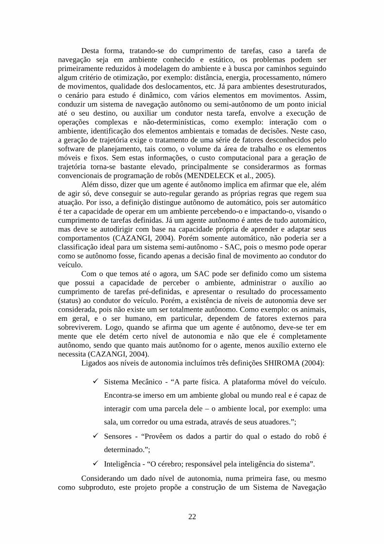
Ligados aos níveis de autonomia incluímos três definições SHIROMA (2004):
� Sistema Mecânico - “A parte física. A plataforma móvel do veículo.
Encontra-se imerso em um ambiente global ou mundo real e é capaz de
interagir com uma parcela dele – o ambiente local, por exemplo: uma
sala, um corredor ou uma estrada, através de seus atuadores.”;
� Sensores - “Provêem os dados a partir do qual o estado do robô é
determinado.”;
� Inteligência - “O cérebro; responsável pela inteligência do sistema”.
Considerando um dado nível de autonomia, numa primeira fase, ou mesmo como subproduto, este projeto propõe a construção de um Sistema de Navegação
23
Semi-Autônomo de Assistência ao Condutor - SAC. Através de um Sistema de Simulação de Realidade Virtual - SRV, inicialmente Não-Imersiva, para Assistência ao Condutor, seu objetivo será auxiliar um condutor durante o cumprimento de tarefas pré-definidas, executadas em ambientes desconhecidos e dinâmicos. Desta forma, incluindo-se o condutor, os quatro componentes: Condutor, Sistema Mecânico, Sensores e Inteligência, deverão interagir continuamente objetivando o cumprimento de tarefas de navegação.
O objetivo principal desta primeira fase será o cumprimento de tarefas em deslocamentos entre pontos pré-determinados em ambiente desestruturados, a partir de informações disponibilizadas por um sistema de posicionamento global. Conhecidos os pontos de origem e destino, durante o deslocamento, o sistema deverá ser capaz de identificar a área de navegação em relação aos seus obstáculos, alertando o condutor sobre possíveis colisões, e aprendendo com os movimentos executados.
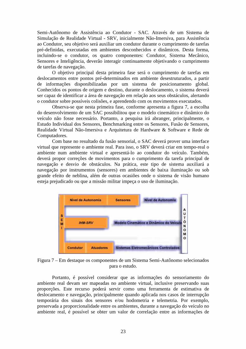
Observa-se que nesta primeira fase, conforme apresenta a figura 7, a escolha do desenvolvimento de um SAC possibilitou que o modelo cinemático e dinâmico do veículo não fosse necessário. Portanto, a pesquisa irá abranger, principalmente, o Estudo Individual dos Sensores, Benchmarking entre os Sensores, Fusão de Sensores, Realidade Virtual Não-Imersiva e Arquitetura de Hardware & Software e Rede de Computadores.
Com base no resultado da fusão sensorial, o SAC deverá prover uma interface virtual que represente o ambiente real. Para isso, o SRV deverá criar em tempo-real o ambiente num ambiente virtual e apresentá-lo ao condutor do veículo. Também, deverá propor correções de movimentos para o cumprimento da tarefa principal de navegação e desvio de obstáculos. Na prática, este tipo de sistema auxiliará a navegação por instrumentos (sensores) em ambientes de baixa iluminação ou sob grande efeito de neblina, além de outras ocasiões onde o sistema de visão humano esteja prejudicado ou que a missão militar impeça o uso de iluminação.
Figura 7 – Em destaque os componentes de um Sistema Semi-Autônomo selecionados para o estudo.
Portanto, é possível considerar que as informações do sensoriamento do
ambiente real devam ser mapeadas no ambiente virtual, inclusive preservando suas proporções. Este recurso poderá servir como uma ferramenta de estimativa de deslocamento e navegação, principalmente quando aplicada nos casos de interrupção temporária dos sinais dos sensores e/ou hodometria e telemetria. Por exemplo, preservada a proporcionalidade entre os ambientes, durante a navegação do veículo no ambiente real, é possível se obter um valor de correlação entre as informações de
24
posicionamento local & global e deslocamentos realizados no ambiente virtual (caso permaneçam as informações de posicionamento global e de hodometria do veículo). Havendo pane no equipamento de posicionamento global - GPS, a partir de um valor estimado no ambiente virtual (caso permaneçam as informações de telemetria e hodometria do veículo ou vice-versa), poderia ser mantido o controle sobre o deslocamento a partir de posicionamentos relativos do veículo no ambiente virtual, preservando o cumprimento de tarefas. Estes resultados também se enquadram nos requisitos dos sistemas de reconhecimento e vigilância e observação, quando operados remotamente.
Nos desafios Grand Challenge e Urban Challenge, organizados pelo DARPA, manter as informações de posicionamento para o cumprimento das tarefas era um pré-requisito dos sistemas de navegação, pois estes deviam manter o controle sobre a execução da tarefa independente do perfeito funcionamento do sensor GPS.
Para que a relação homem-máquina possa ocorrer, é indispensável o uso das interfaces e da interatividade. Sem estes dois fundamentos, é impossível haver qualquer tipo de relação homem-máquina. Uma Interface Homem-Máquina – IHM compreende os comportamentos do usuário, software, hardware e do ambiente - locais físicos e seus impactos. Basicamente, a IHM faz a conexão entre a imagem externa do sistema e o homem. A interface permite que o sistema mantenha contato com o usuário, sendo a interação de atuação recíproca. O usuário possui um modelo mental de como o sistema funciona, e o sistema possui um modelo cognitivo de como o usuário se comporta.
A Realidade Virtual - RV) ou ambiente virtual, é uma tecnologia de interface entre um usuário e um sistema computacional. Seu objetivo é recriar ao máximo a sensação de realidade para um indivíduo, levando-o a adotar essa interação como uma de suas realidades temporais. Como pré-requisito, deve ser realizada em tempo real, com o uso de técnicas e de equipamentos computacionais que ajudem na ampliação do sentimento de presença do usuário. Além disso, a RV como ferramenta de simulação da realidade através da tecnologia, também se estende a uma apreensão de um universo não real, um universo de ícones e símbolos, mas permeando em um processo de significação desse falso universo.
Originalmente, o termo RV significava um sistema totalmente imersivo, entretanto, a palavra tem sido utilizada para descrever sistemas que não utilizam componentes como luvas digitais, óculos estereoscópicos etc. Segundo a literatura, a RV não-imersiva é realizada com o uso de um monitor comum no qual o utilizador manipula o ambiente virtual através de um dispositivo de entrada. Alguns dispositivos importantes à RV: Percepção sensorial; Hardware; Software; Interface com o usuário (Simulações em tempo real). Além de ser uma boa ferramenta para comunicação com o usuário, um ambiente simulado também permite o desenvolvimento de ambientes de simulação para teste do sistema de navegação. Testes executados em ambiente real, em geral, consomem uma quantidade considerável de tempo e recursos da equipe. Adicionalmente, as variações ambientais aumentam a dificuldade de testes específicos.
Destaca-se, ainda, o aproveitamento desta pesquisa para o desenvolvimento de sistemas de simulação para detecção de alvos em sistemas de armamentos semi-automatizados, por exemplo, utilizando os recursos do Reparo Automatizado de Metralhadora, ora em desenvolvimento no Centro Tecnológico do Exército - CTEx.
Para viabilizar a pesquisa, vislumbra-se a participação de vários pesquisadores e especialistas, de diferentes instituições. Desta forma, assim como nos trabalhos submetidos ao DARPA, na ocasião do Grand Challenge e Urban Challenge, optou-se
25
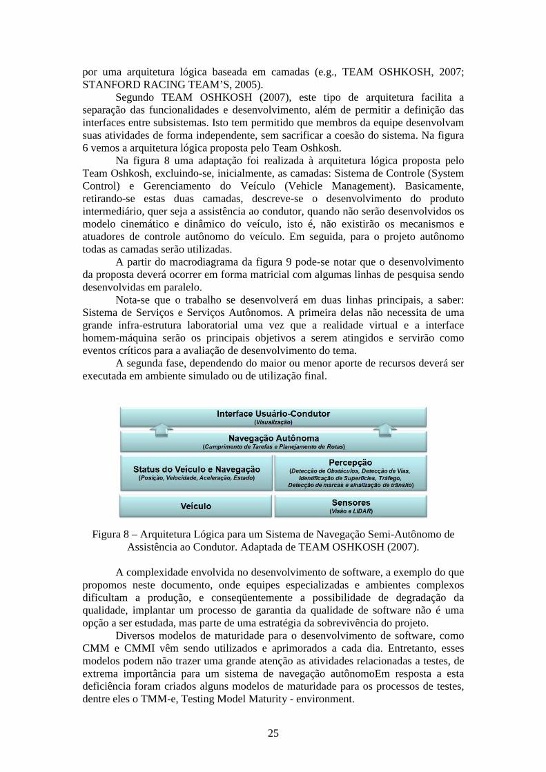
por uma arquitetura lógica baseada em camadas (e.g., TEAM OSHKOSH, 2007; STANFORD RACING TEAM’S, 2005).
Segundo TEAM OSHKOSH (2007), este tipo de arquitetura facilita a separação das funcionalidades e desenvolvimento, além de permitir a definição das interfaces entre subsistemas. Isto tem permitido que membros da equipe desenvolvam suas atividades de forma independente, sem sacrificar a coesão do sistema. Na figura 6 vemos a arquitetura lógica proposta pelo Team Oshkosh.
Na figura 8 uma adaptação foi realizada à arquitetura lógica proposta pelo Team Oshkosh, excluindo-se, inicialmente, as camadas: Sistema de Controle (System Control) e Gerenciamento do Veículo (Vehicle Management). Basicamente, retirando-se estas duas camadas, descreve-se o desenvolvimento do produto intermediário, quer seja a assistência ao condutor, quando não serão desenvolvidos os modelo cinemático e dinâmico do veículo, isto é, não existirão os mecanismos e atuadores de controle autônomo do veículo. Em seguida, para o projeto autônomo todas as camadas serão utilizadas.
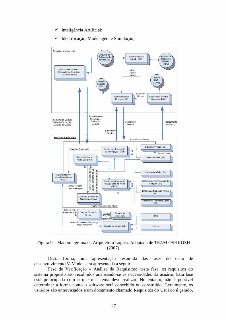
A partir do macrodiagrama da figura 9 pode-se notar que o desenvolvimento da proposta deverá ocorrer em forma matricial com algumas linhas de pesquisa sendo desenvolvidas em paralelo.
Nota-se que o trabalho se desenvolverá em duas linhas principais, a saber: Sistema de Serviços e Serviços Autônomos. A primeira delas não necessita de uma grande infra-estrutura laboratorial uma vez que a realidade virtual e a interface homem-máquina serão os principais objetivos a serem atingidos e servirão como eventos críticos para a avaliação de desenvolvimento do tema.
A segunda fase, dependendo do maior ou menor aporte de recursos deverá ser executada em ambiente simulado ou de utilização final.
Figura 8 – Arquitetura Lógica para um Sistema de Navegação Semi-Autônomo de Assistência ao Condutor. Adaptada de TEAM OSHKOSH (2007).
A complexidade envolvida no desenvolvimento de software, a exemplo do que
propomos neste documento, onde equipes especializadas e ambientes complexos dificultam a produção, e conseqüentemente a possibilidade de degradação da qualidade, implantar um processo de garantia da qualidade de software não é uma opção a ser estudada, mas parte de uma estratégia da sobrevivência do projeto.
Diversos modelos de maturidade para o desenvolvimento de software, como CMM e CMMI vêm sendo utilizados e aprimorados a cada dia. Entretanto, esses modelos podem não trazer uma grande atenção as atividades relacionadas a testes, de extrema importância para um sistema de navegação autônomoEm resposta a esta deficiência foram criados alguns modelos de maturidade para os processos de testes, dentre eles o TMM-e, Testing Model Maturity - environment.
26
Em resposta a esta deficiência foram criados alguns modelos de maturidade para os processos de testes, dentre eles o TMM-e, Testing Model Maturity - environment.
O Testing Maturity Model -TMM foi desenvolvido pelo Illinois Institut of Tecnology, como um guia para melhoria de processos de testes e é apresentado como um complemento ao modelo CMM. Sua estrutura está baseada em níveis de maturidade, que possuem requisitos para avaliação do grau de maturidade de um processo. A exemplo do CMM, e de seu sucessor CMMI, existem cinco níveis e para cada nível foram definidos objetivos de maturidade, que correspondem a um conjunto de atividades e responsabilidades (associadas a papéis), em um determinado domínio, como planejamento de testes. Quando estas atividades são executadas de forma adequada contribuem para a melhoria do processo de testes.
Um processo de software pode ser definido como um conjunto de atividades executadas para desenvolver, manutenir e gerenciar sistemas. Estas atividades podem ser compostas por outras atividades, seja realizada por pessoas, que possuem um determinado papel no processo, que podem utilizar ferramentas e modelos que automatizem e facilitem os seus trabalhos. À medida que o processo flui, artefatos (código, documentos, modelos e diagramas) são produzidos, atualizados e consumidos nas atividades realizadas.
Uma ferramenta conhecida como IEEE Standard Glossary of Software Engineering Terminology descreve o ciclo de vida do software. O ciclo de vida de software engloba, tipicamente, as fases de requisito, design, implementação, teste, instalação, operação, manutenção e desativação. O modelo de ciclo de vida V-Model associa cada atividade de desenvolvimento com uma atividade de teste ou validação no mesmo nível de abstração dos produtos gerados na fase. Ao final de cada fase, testadores avaliam formalmente os artefatos de cada fase, revisando e aprovando o documento de requisitos ao final da fase de requisitos, gerando testes, com base nos artefatos gerados, que deverão ser realizados posteriormente.
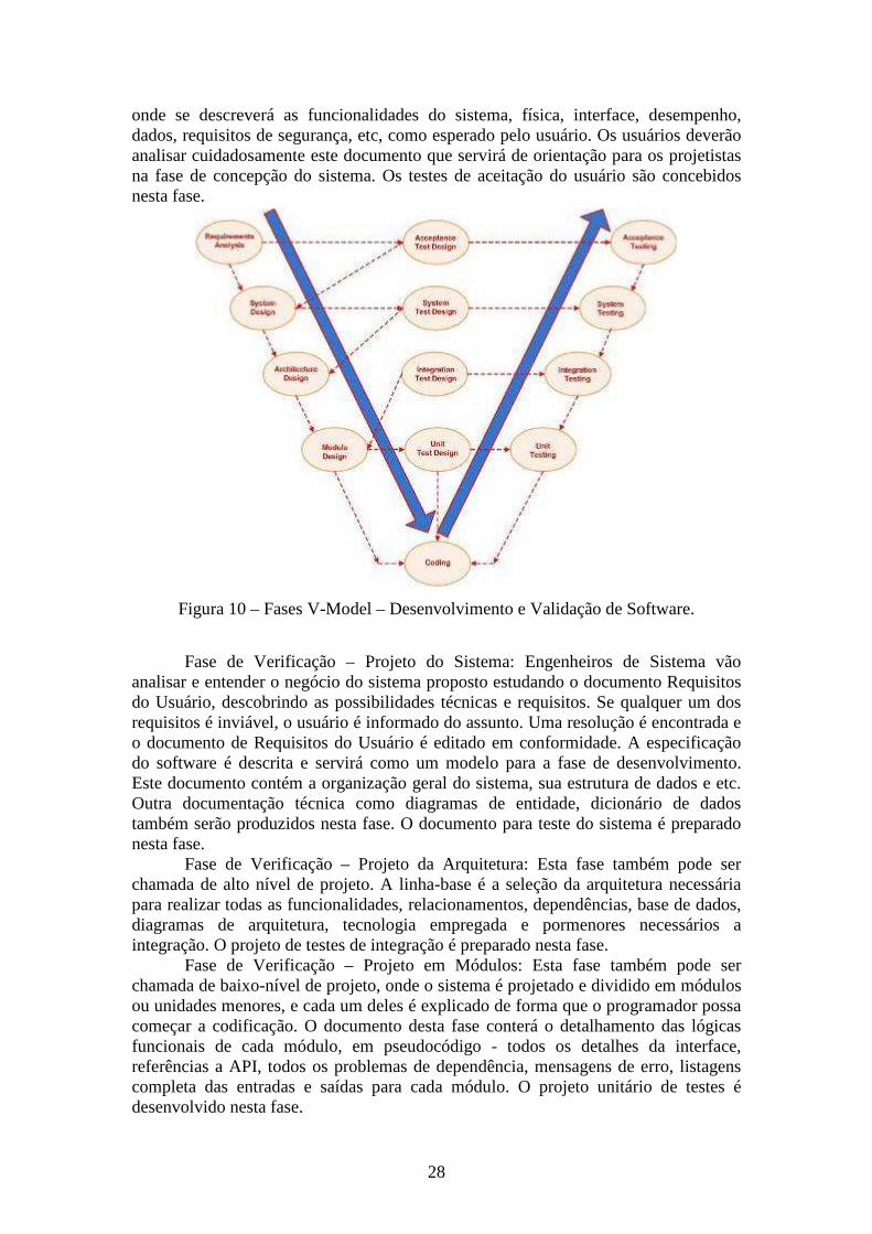
No V-Model o envolvimento dos testadores se dá desde o início do desenvolvimento possibilitando que defeitos sejam descobertos mais cedo que em modelos tradicionais. As fases são apresentadas na figura 10.
Na última multi-conferência realizada no estado do Texas-EUA, 2008 IEEE Multi-conference on Systems and Control (MSC), foi apresentado um caso prático do uso do V-Model (ou V-Shape - Software Development Validation) para o desenvolvimento e validação de softwares da NGC Aerospace Ltd. O título da apresentação foi Computer-Aided Software Design for Spacecraft Guidance, Navigation an Control. O palestrante foi o atual presidente da NGC, Jean de Lafontaine.
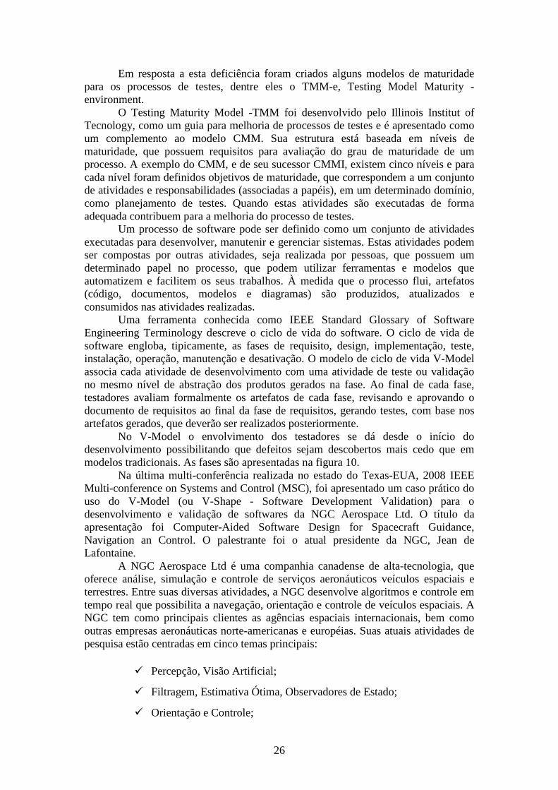
A NGC Aerospace Ltd é uma companhia canadense de alta-tecnologia, que oferece análise, simulação e controle de serviços aeronáuticos veículos espaciais e terrestres. Entre suas diversas atividades, a NGC desenvolve algoritmos e controle em tempo real que possibilita a navegação, orientação e controle de veículos espaciais. A NGC tem como principais clientes as agências espaciais internacionais, bem como outras empresas aeronáuticas norte-americanas e européias. Suas atuais atividades de pesquisa estão centradas em cinco temas principais:
� Percepção, Visão Artificial;
� Filtragem, Estimativa Ótima, Observadores de Estado;
� Orientação e Controle;
27
� Inteligência Artificial;
� Identificação, Modelagem e Simulação;
Figura 9 – Macrodiagrama da Arquitetura Lógica. Adaptada de TEAM OSHKOSH (2007).
Desta forma, uma apresentação resumida das fases do ciclo de
desenvolvimento V-Model será apresentada a seguir: Fase de Verificação – Análise de Requisitos: nesta fase, os requisitos do
sistema proposto são recolhidos analisando-se as necessidades do usuário. Esta fase está preocupada com o que o sistema deve realizar. No entanto, não é possível determinar a forma como o software será concebido ou construído. Geralmente, os usuários são entrevistados e um documento chamado Requisitos do Usuário é gerado,
28
onde se descreverá as funcionalidades do sistema, física, interface, desempenho, dados, requisitos de segurança, etc, como esperado pelo usuário. Os usuários deverão analisar cuidadosamente este documento que servirá de orientação para os projetistas na fase de concepção do sistema. Os testes de aceitação do usuário são concebidos nesta fase.
Figura 10 – Fases V-Model – Desenvolvimento e Validação de Software.
Fase de Verificação – Projeto do Sistema: Engenheiros de Sistema vão
analisar e entender o negócio do sistema proposto estudando o documento Requisitos do Usuário, descobrindo as possibilidades técnicas e requisitos. Se qualquer um dos requisitos é inviável, o usuário é informado do assunto. Uma resolução é encontrada e o documento de Requisitos do Usuário é editado em conformidade. A especificação do software é descrita e servirá como um modelo para a fase de desenvolvimento. Este documento contém a organização geral do sistema, sua estrutura de dados e etc. Outra documentação técnica como diagramas de entidade, dicionário de dados também serão produzidos nesta fase. O documento para teste do sistema é preparado nesta fase.
Fase de Verificação – Projeto da Arquitetura: Esta fase também pode ser chamada de alto nível de projeto. A linha-base é a seleção da arquitetura necessária para realizar todas as funcionalidades, relacionamentos, dependências, base de dados, diagramas de arquitetura, tecnologia empregada e pormenores necessários a integração. O projeto de testes de integração é preparado nesta fase.
Fase de Verificação – Projeto em Módulos: Esta fase também pode ser chamada de baixo-nível de projeto, onde o sistema é projetado e dividido em módulos ou unidades menores, e cada um deles é explicado de forma que o programador possa começar a codificação. O documento desta fase conterá o detalhamento das lógicas funcionais de cada módulo, em pseudocódigo - todos os detalhes da interface, referências a API, todos os problemas de dependência, mensagens de erro, listagens completa das entradas e saídas para cada módulo. O projeto unitário de testes é desenvolvido nesta fase.
29
Fase de Validação – Unidade de Testes: Implicam na primeira fase do processo de testes dinâmicos. Envolvem análise do código fonte com a intenção de eliminar erros, além da verificação dos códigos eficientes que aderem às normas aprovadas para codificação.
Fase de Validação – Teste de Integração: Todos os módulos serão testados em conjunto para expor as falhas nas interações entre os componentes integrados. É feito utilizando o teste de integração de projeto elaborado durante a fase de arquitetura do projeto. Permite-se a utilização de softwares testadores.
Fase de Validação – Teste do Sistema: Irá comparar as especificações do sistema contra o próprio sistema, utilizando-se de documentos de concepção do sistema. Permite-se a utilização de sistema automatizado nesta fase.
Fase de Validação – Teste do Sistema: Irá comparar as especificações do sistema contra o próprio sistema, utilizando-se de documentos de concepção do sistema. Permite-se a utilização de sistema automatizado nesta fase.
Fase de Validação – Teste de Aceitação do Usuário: Determinar se o sistema satisfaz os critérios, testar o software no "mundo real".
Realidade Virtual e Interface Homem-Máquina Para que a relação homem-máquina possa ocorrer, é indispensável o uso das
interfaces e da interatividade. Sem estes dois fundamentos, é impossível haver qualquer tipo de relação homem-máquina.
Uma Interface Homem-Máquina -IHM compreende os comportamentos do usuário, software, hardware e do ambiente - locais físicos e seus impactos (TURNELL, 1998). Basicamente, a IHM faz a conexão entre a imagem externa do sistema e o homem. A interface permite que o sistema mantenha contato com o usuário, sendo a interação de atuação recíproca. O usuário possui um modelo mental de como o sistema funciona, e o sistema possui um modelo cognitivo de como o usuário se comporta.
A Realidade Virtual - RV, ou ambiente virtual, é uma tecnologia de interface entre um usuário e um sistema computacional. Seu objetivo é recriar ao máximo a sensação de realidade para um indivíduo, levando-o a adotar essa interação como uma de suas realidades temporais. Como pré-requisito, deve ser realizada em tempo real, com o uso de técnicas e de equipamentos computacionais que ajudem na ampliação do sentimento de presença do usuário (e.g., JIMING LIU et al., 2003; GAVA. T. B. S., 2003; GAVA. T. B. S., 2003).
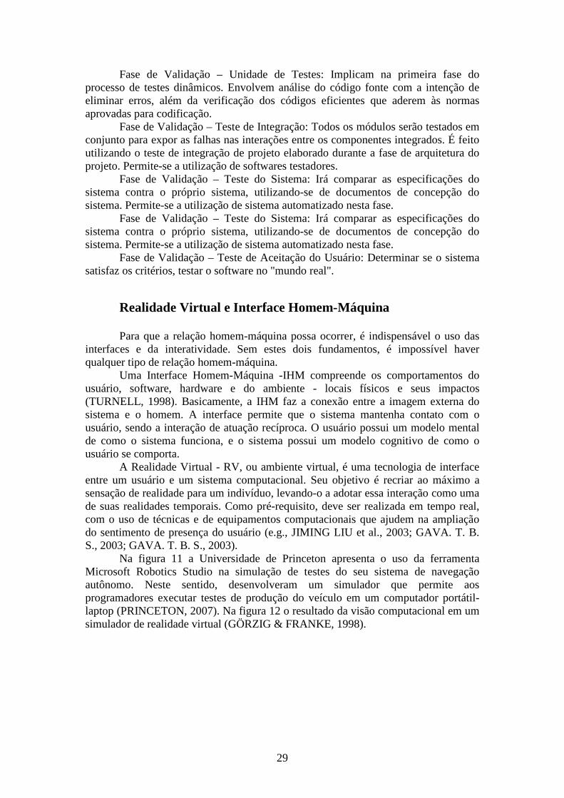
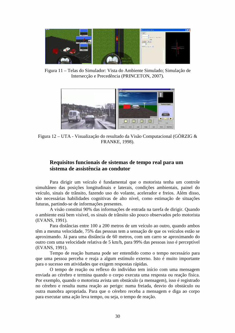
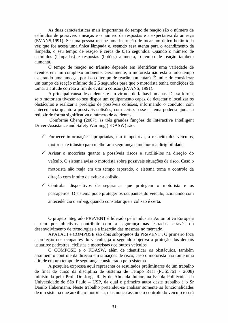
Na figura 11 a Universidade de Princeton apresenta o uso da ferramenta Microsoft Robotics Studio na simulação de testes do seu sistema de navegação autônomo. Neste sentido, desenvolveram um simulador que permite aos programadores executar testes de produção do veículo em um computador portátil-laptop (PRINCETON, 2007). Na figura 12 o resultado da visão computacional em um simulador de realidade virtual (GÖRZIG & FRANKE, 1998).
30
Figura 11 – Telas do Simulador: Vista do Ambiente Simulado; Simulação de Intersecção e Precedência (PRINCETON, 2007).
Figura 12 – UTA - Visualização do resultado da Visão Computacional (GÖRZIG & FRANKE, 1998).
Requisitos funcionais de sistemas de tempo real para um sistema de assistência ao condutor Para dirigir um veículo é fundamental que o motorista tenha um controle
simultâneo das posições longitudinais e laterais, condições ambientais, painel do veículo, sinais de trânsito, fazendo uso do volante, acelerador e freios. Além disso, são necessárias habilidades cognitivas de alto nível, como estimação de situações futuras, partindo-se de informações presentes.
A visão constitui 90% das informações de entrada na tarefa de dirigir. Quando o ambiente está bem visível, os sinais de trânsito são pouco observados pelo motorista (EVANS, 1991).
Para distâncias entre 100 a 200 metros de um veículo ao outro, quando ambos têm a mesma velocidade, 75% das pessoas tem a sensação de que os veículos estão se aproximando. Já para uma distância de 60 metros, com um carro se aproximando do outro com uma velocidade relativa de 5 km/h, para 99% das pessoas isso é perceptível (EVANS, 1991).
Tempo de reação humana pode ser entendido como o tempo necessário para que uma pessoa perceba e reaja a algum estímulo externo. Isto é muito importante para o sucesso em atividades que exigem respostas rápidas.
O tempo de reação ou reflexo do indivíduo tem início com uma mensagem enviada ao cérebro e termina quando o corpo executa uma resposta ou reação física. Por exemplo, quando o motorista avista um obstáculo (a mensagem), isso é registrado no cérebro e resulta numa reação ao perigo: numa freiada, desvio do obstáculo ou outra manobra apropriada. Para que o cérebro receba a mensagem e diga ao corpo para executar uma ação leva tempo, ou seja, o tempo de reação.
31
As duas características mais importantes do tempo de reação são o número de estímulos de possíveis ameaças e o número de respostas e a expectativa da ameaça (EVANS,1991). Se uma pessoa recebe uma instrução de tocar um único botão toda vez que for acesa uma única lâmpada e, estando essa atenta para o acendimento da lâmpada, o seu tempo de reação é cerca de 0,15 segundos. Quando o número de estímulos (lâmpadas) e respostas (botões) aumenta, o tempo de reação também aumenta.
O tempo de reação no trânsito depende em identificar uma variedade de eventos em um complexo ambiente. Geralmente, o motorista não está a todo tempo esperando uma ameaça, por isso o tempo de reação aumentará. É indicado considerar um tempo de reação mínimo de 2,5 segundos para que o motorista tenha condições de tomar a atitude correta a fim de evitar a colisão (EVANS, 1991).
A principal causa de acidentes é em virtude de falhas humanas. Dessa forma, se o motorista tivesse ao seu dispor um equipamento capaz de detectar e localizar os obstáculos e realizar a predição de possíveis colisões, informando o condutor com antecedência quanto a possíveis colisões, com certeza esse sistema poderia ajudar a reduzir de forma significativa o número de acidentes.
Conforme Cheng (2007), as três grandes funções do Interactive Intelligent Driver-Assistance and Safety Warning (I²DASW) são:
� Fornecer informações apropriadas, em tempo real, a respeito dos veículos,
motorista e trânsito para melhorar a segurança e melhorar a dirigibilidade.
� Avisar o motorista quanto a possíveis riscos e auxiliá-los na direção do
veículo. O sistema avisa o motorista sobre possíveis situações de risco. Caso o
motorista não reaja em um tempo esperado, o sistema toma o controle da
direção com intuito de evitar a colisão.
� Controlar dispositivos de segurança que protegem o motorista e os
passageiros. O sistema pode proteger os ocupantes do veículo, acionando com
antecedência o airbag, quando constatar que a colisão é certa.
O projeto integrado PReVENT é liderado pela Industria Automotiva Européia e tem por objetivos contribuir com a segurança nas estradas, através do desenvolvimento de tecnologias e a inserção das mesmas no mercado.
APALACI e COMPOSE são dois subprojetos da PReVENT . O primeiro foca a proteção dos ocupantes do veículo, já o segundo objetiva a proteção dos demais usuários: pedestres, ciclistas e motoristas dos outros veículos.
O COMPOSE e o I²DASW, além de identificar os obstáculos, também assumem o controle da direção em situações de risco, caso o motorista não tome uma atitude em um tempo de segurança considerado pelo sistema.
A pesquisa expressa aqui representa os resultados preliminares de um trabalho de final de curso da disciplina de Sistema de Tempo Real (PCS5761 - 2008) ministrada pelo Prof. Dr. Jorge Rady de Almeida Júnior, na Escola Politécnica da Universidade de São Paulo – USP, da qual o primeiro autor deste trabalho é o Sr Danilo Habermann. Neste trabalho pretendeu-se analisar somente as funcionalidades de um sistema que auxilia o motorista, mas nunca assume o controle do veículo e será
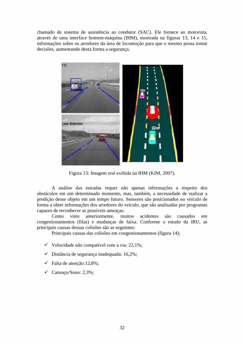
32
chamado de sistema de assistência ao condutor (SAC). Ele fornece ao motorista, através de uma interface homem-máquina (IHM), mostrada na figuras 13, 14 e 15, informações sobre os arredores da área de locomoção para que o mesmo possa tomar decisões, aumentando desta forma a segurança.
Figura 13: Imagem real exibida na IHM (KIM, 2007).
A análise das estradas requer não apenas informações a respeito dos
obstáculos em um determinado momento, mas, também, a necessidade de realizar a predição desse objeto em um tempo futuro. Sensores são posicionados no veículo de forma a obter informações dos arredores do veículo, que são analisadas por programas capazes de reconhecer as possíveis ameaças.
Como visto anteriormente, muitos acidentes são causados em congestionamentos (filas) e mudanças de faixa. Conforme o estudo da IRU, as principais causas dessas colisões são as seguintes:
Principais causas das colisões em congestionamentos (figura 14);
� Velocidade não compatível com a via: 22,1%;
� Distância de segurança inadequada: 16,2%;
� Falta de atenção:12,8%;
� Cansaço/Sono: 2,3%;
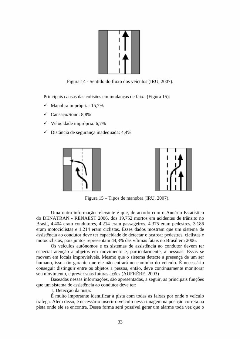
33
Figura 14 - Sentido do fluxo dos veículos (IRU, 2007).
Principais causas das colisões em mudanças de faixa (Figura 15):
� Manobra imprópria: 15,7%
� Cansaço/Sono: 8,8%
� Velocidade imprópria: 6,7%
� Distância de segurança inadequada: 4,4%
Figura 15 – Tipos de manobra (IRU, 2007).
Uma outra informação relevante é que, de acordo com o Anuário Estatístico
do DENATRAN - RENAEST 2006, dos 19.752 mortos em acidentes de trânsito no Brasil, 4.404 eram condutores, 4.214 eram passageiros, 4.375 eram pedestres, 3.186 eram motociclistas e 1.214 eram ciclistas. Esses dados mostram que um sistema de assistência ao condutor deve ter capacidade de detectar e rastrear pedestres, ciclistas e motociclistas, pois juntos representam 44,3% das vítimas fatais no Brasil em 2006.
Os veículos autônomos e os sistemas de assistência ao condutor devem ter especial atenção a objetos em movimento e, particularmente, a pessoas. Essas se movem em locais imprevisíveis. Mesmo que o sistema detecte a presença de um ser humano, isso não garante que ele não entrará no caminho do veículo. É necessário conseguir distinguir entre os objetos a pessoa, então, deve continuamente monitorar seu movimento, e prever suas futuras ações (AUFRÈRE, 2003)
Baseadas nessas informações, são apresentadas, a seguir, as principais funções que um sistema de assistência ao condutor deve ter:
1. Detecção da pista: É muito importante identificar a pista com todas as faixas por onde o veículo
trafega. Além disso, é necessário inserir o veículo nessa imagem na posição correta na pista onde ele se encontra. Dessa forma será possível gerar um alarme toda vez que o
34
veículo começa a invadir as outras faixas ou a sair da pista. Para identificar a pista no momento da partida é necessário identificar a posição e a direção dos limites da faixa. Há duas maneiras de se fazer isso, uma delas é inserir marcadores magnéticos nas pistas. No entanto, há um grande custo envolvido nesta operação. O modo mais usual é pintar os limites laterais da pista e usar visão computacional para identificar o local de rodagem. Quando se toma a imagem de uma rodovia, pode-se verificar que as faixas dos limites da pista têm mais intensidade do que a área pavimentada, facilitando a identificação (CHENG, 2007).
2. Detecção e Rastreamento de Veículos: Todos os veículos que estão nos arredores do veículo que possui o SAC devem
ser detectados e rastreados. É muito importante que o sistema possa determinar as velocidades relativas dos demais veículos e realizar uma estimação sobre os riscos de haver uma colisão. Em geral, usam-se sensores do tipo LIDAR, SONAR ou RADAR para conhecer a distância e a direção em que se encontra o obstáculo e câmeras para ajudar a identificar qual é o tipo do obstáculo. Algoritmos procuram identificar alguns padrões específicos na imagem como forma e simetria.
3. Detecção e rastreamento de pedestres: De acordo com Cheng (2007), sensores infravermelhos são essenciais para
realizar uma precisa detecção de pessoas. O rastreamento de pessoas é uma das tarefas mais difíceis de ser realizada devido ao comportamento imprevisível das mesmas.
4. Detecção de objetos fixos: É importante localizar os demais obstáculos que compõem as ruas e as
rodovias, como placas de trânsito, barreiras e árvores. Em geral usam-se sensores RADAR conjugados com câmeras de vídeo.
5. Reconhecimento de sinais de trânsito: Como mostrado anteriormente, a velocidade incompatível com a pista é
causadora de inúmeros acidentes. Dessa forma, faz-se necessário identificar as placas com a sinalização da velocidade máxima permitida. Além disso, é importante identificar outros sinais como “PARE” e semáforos para evitar que motoristas distraídos passem por cruzamentos em momentos indevidos.
6. Predição e aviso de colisões: Dada a localização dos objetos móveis e fixos inseridos na imagem virtual da
pista, bem como a velocidade relativa e a direção dos mesmos, e dados como velocidade, direção e aceleração do veículo com o SAC, é possível calcular o tempo de colisão para cada objeto. Podem ser configurados dois tipos de aviso: avisos de alerta e avisos de emergência, dependendo do grau de risco.
Atualmente, deparamo-nos com uma quantidade crescente de aplicações que apresentam comportamentos definidos segundo restrições temporais. Alguns exemplos dessas aplicações se encontram no controle de plantas industriais, de tráfego aéreo ou ferroviário. Sistemas que apresentam tal característica, de estarem sujeitas a restrições temporais, são comumente identificadas como Sistemas de Tempo Real.
Um sistema de tempo real - STR deve satisfazer restrições de tempo de resposta sob o risco de falhar, provocando graves acidentes (LAPLANT,2004).
Um sistema de assistência ao condutor pode ser enquadrado como um sistema de tempo real, pois informações erradas ou defasadas no tempo não poderão atender às necessidades do motorista e causar um acidente. Por exemplo, suponha que o motorista esteja trafegando em longo trecho reto de uma rodovia e por estar desatento não percebe que seu veículo está se aproximando de forma perigosa de um veículo a frente, se o SAC não conseguir calcular de forma correta as informações e não enxergar o perigo, ou ainda, se não conseguir processar em um tempo suficiente para
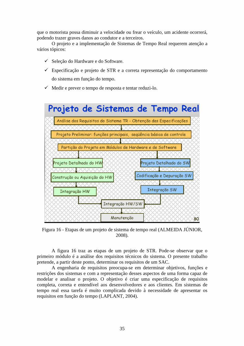
35
que o motorista possa diminuir a velocidade ou frear o veículo, um acidente ocorrerá, podendo trazer graves danos ao condutor e a terceiros.
O projeto e a implementação de Sistemas de Tempo Real requerem atenção a vários tópicos:
� Seleção do Hardware e do Software.
� Especificação e projeto de STR e a correta representação do comportamento
do sistema em função do tempo.
� Medir e prever o tempo de resposta e tentar reduzi-lo.
Figura 16 - Etapas de um projeto de sistema de tempo real (ALMEIDA JÚNIOR, 2008).
A figura 16 traz as etapas de um projeto de STR. Pode-se observar que o primeiro módulo é a análise dos requisitos técnicos do sistema. O presente trabalho pretende, a partir deste ponto, determinar os requisitos de um SAC.
A engenharia de requisitos preocupa-se em determinar objetivos, funções e restrições dos sistemas e com a representação desses aspectos de uma forma capaz de modelar e analisar o projeto. O objetivo é criar uma especificação de requisitos completa, correta e entendível aos desenvolvedores e aos clientes. Em sistemas de tempo real essa tarefa é muito complicada devido à necessidade de apresentar os requisitos em função do tempo (LAPLANT, 2004).
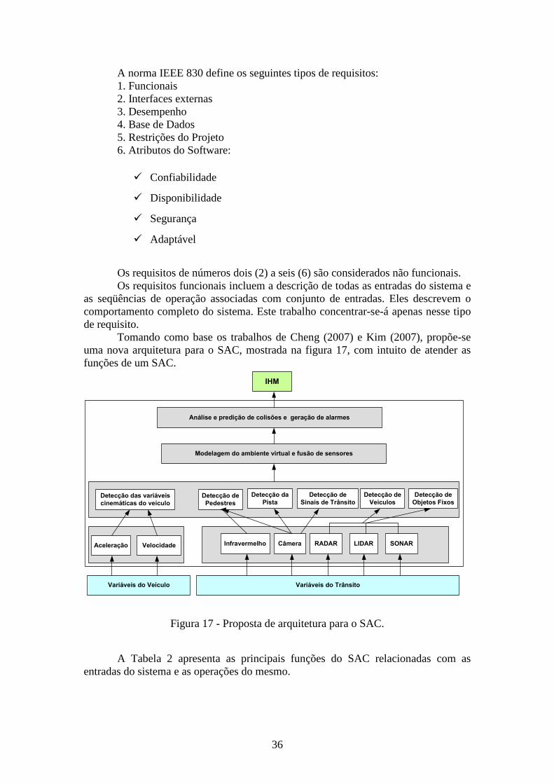
36
A norma IEEE 830 define os seguintes tipos de requisitos: 1. Funcionais 2. Interfaces externas 3. Desempenho 4. Base de Dados 5. Restrições do Projeto 6. Atributos do Software:
� Confiabilidade
� Disponibilidade
� Segurança
� Adaptável
Os requisitos de números dois (2) a seis (6) são considerados não funcionais. Os requisitos funcionais incluem a descrição de todas as entradas do sistema e
as seqüências de operação associadas com conjunto de entradas. Eles descrevem o comportamento completo do sistema. Este trabalho concentrar-se-á apenas nesse tipo de requisito.
Tomando como base os trabalhos de Cheng (2007) e Kim (2007), propõe-se uma nova arquitetura para o SAC, mostrada na figura 17, com intuito de atender as funções de um SAC.
CâmeraInfravermelho RADAR LIDAR SONAR
Variáveis do Trânsito
Detecção da
Pista
Detecção de
Sinais de TrânsitoDetecção de
Pedestres
Detecção de
Veículos
Detecção de
Objetos Fixos
Variáveis do Veículo
Aceleração Velocidade
Detecção das variáveis
cinemáticas do veículo
Modelagem do ambiente virtual e fusão de sensores
Análise e predição de colisões e geração de alarmes
IHM
Figura 17 - Proposta de arquitetura para o SAC.
A Tabela 2 apresenta as principais funções do SAC relacionadas com as entradas do sistema e as operações do mesmo.
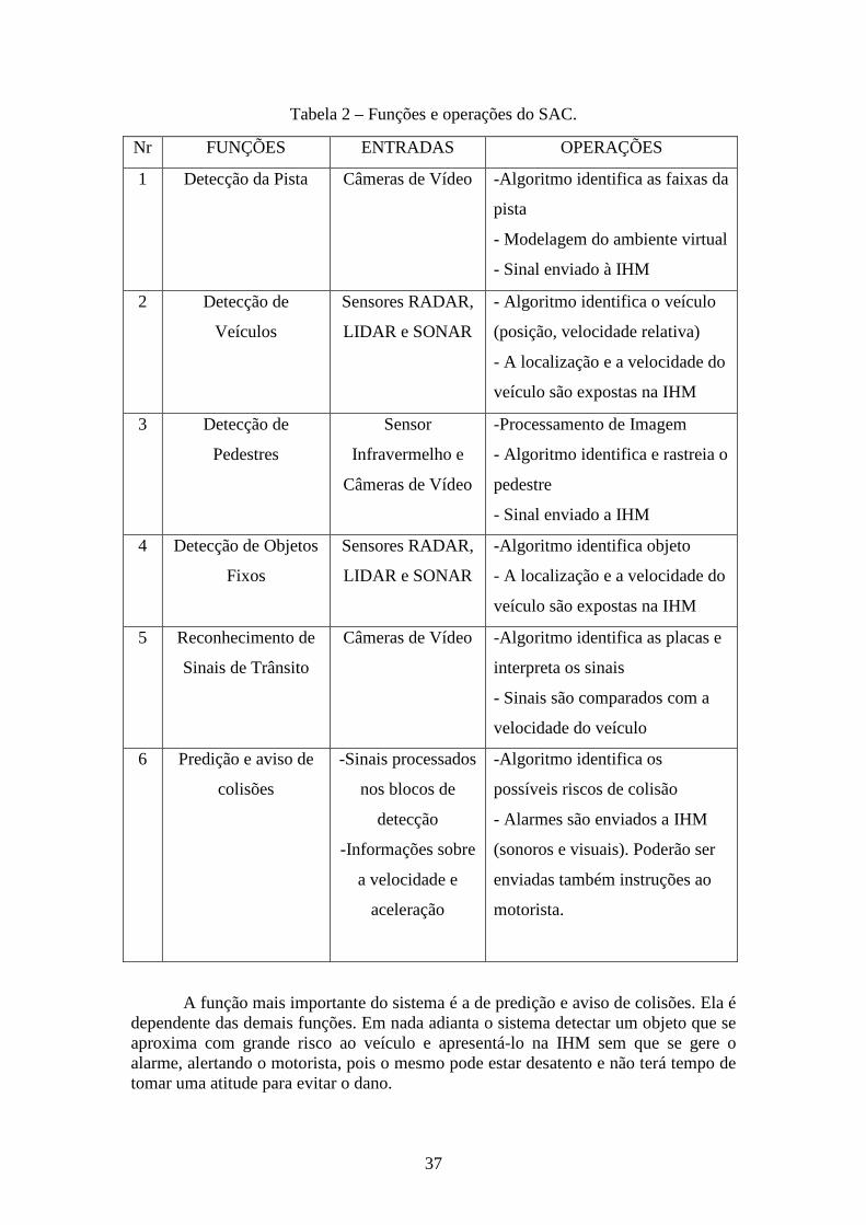
37
Tabela 2 – Funções e operações do SAC.
Nr FUNÇÕES ENTRADAS OPERAÇÕES
1 Detecção da Pista Câmeras de Vídeo -Algoritmo identifica as faixas da
pista
- Modelagem do ambiente virtual
- Sinal enviado à IHM
2 Detecção de
Veículos
Sensores RADAR,
LIDAR e SONAR
- Algoritmo identifica o veículo
(posição, velocidade relativa)
- A localização e a velocidade do
veículo são expostas na IHM
3 Detecção de
Pedestres
Sensor
Infravermelho e
Câmeras de Vídeo
-Processamento de Imagem
- Algoritmo identifica e rastreia o
pedestre
- Sinal enviado a IHM
4 Detecção de Objetos
Fixos
Sensores RADAR,
LIDAR e SONAR
-Algoritmo identifica objeto
- A localização e a velocidade do
veículo são expostas na IHM
5 Reconhecimento de
Sinais de Trânsito
Câmeras de Vídeo -Algoritmo identifica as placas e
interpreta os sinais
- Sinais são comparados com a
velocidade do veículo
6 Predição e aviso de
colisões
-Sinais processados
nos blocos de
detecção
-Informações sobre
a velocidade e
aceleração
-Algoritmo identifica os
possíveis riscos de colisão
- Alarmes são enviados a IHM
(sonoros e visuais). Poderão ser
enviadas também instruções ao
motorista.
A função mais importante do sistema é a de predição e aviso de colisões. Ela é dependente das demais funções. Em nada adianta o sistema detectar um objeto que se aproxima com grande risco ao veículo e apresentá-lo na IHM sem que se gere o alarme, alertando o motorista, pois o mesmo pode estar desatento e não terá tempo de tomar uma atitude para evitar o dano.
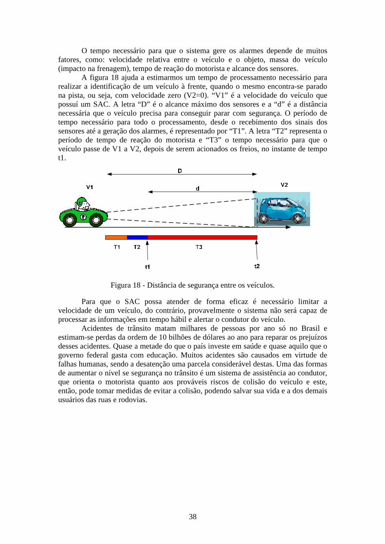
38
O tempo necessário para que o sistema gere os alarmes depende de muitos fatores, como: velocidade relativa entre o veículo e o objeto, massa do veículo (impacto na frenagem), tempo de reação do motorista e alcance dos sensores.
A figura 18 ajuda a estimarmos um tempo de processamento necessário para realizar a identificação de um veículo à frente, quando o mesmo encontra-se parado na pista, ou seja, com velocidade zero (V2=0). “V1” é a velocidade do veículo que possuí um SAC. A letra “D” é o alcance máximo dos sensores e a “d” é a distância necessária que o veículo precisa para conseguir parar com segurança. O período de tempo necessário para todo o processamento, desde o recebimento dos sinais dos sensores até a geração dos alarmes, é representado por “T1”. A letra “T2” representa o período de tempo de reação do motorista e “T3” o tempo necessário para que o veículo passe de V1 a V2, depois de serem acionados os freios, no instante de tempo t1.
Figura 18 - Distância de segurança entre os veículos.
Para que o SAC possa atender de forma eficaz é necessário limitar a velocidade de um veículo, do contrário, provavelmente o sistema não será capaz de processar as informações em tempo hábil e alertar o condutor do veículo.
Acidentes de trânsito matam milhares de pessoas por ano só no Brasil e estimam-se perdas da ordem de 10 bilhões de dólares ao ano para reparar os prejuízos desses acidentes. Quase a metade do que o país investe em saúde e quase aquilo que o governo federal gasta com educação. Muitos acidentes são causados em virtude de falhas humanas, sendo a desatenção uma parcela considerável destas. Uma das formas de aumentar o nível se segurança no trânsito é um sistema de assistência ao condutor, que orienta o motorista quanto aos prováveis riscos de colisão do veículo e este, então, pode tomar medidas de evitar a colisão, podendo salvar sua vida e a dos demais usuários das ruas e rodovias.
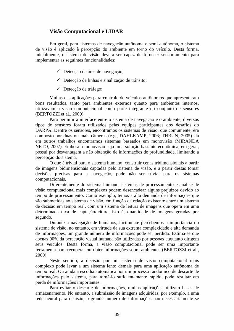
39
Visão Computacional e LIDAR
Em geral, para sistemas de navegação autônoma e semi-autônoma, o sistema de visão é aplicado à percepção do ambiente em torno do veículo. Desta forma, inicialmente, o sistema de visão deverá ser capaz de fornecer sensoriamento para implementar as seguintes funcionalidades:
� Detecção da área de navegação;
� Detecção de linhas e sinalização de trânsito;
� Detecção de tráfego;
Muitas das aplicações para controle de veículos autônomos que apresentaram bons resultados, tanto para ambientes externos quanto para ambientes internos, utilizavam a visão computacional como parte integrante do conjunto de sensores (BERTOZZI et al., 2000).
Para permitir a interface entre o sistema de navegação e o ambiente, diversos tipos de sensores foram utilizados pelas equipes participantes dos desafios do DARPA. Dentre os sensores, encontramos os sistemas de visão, que comumente, era composto por duas ou mais câmeras (e.g., DAHLKAMP, 2006; THRUN, 2005). Já em outros trabalhos encontramos sistemas baseados em monovisão (MIRANDA NETO, 2007). Embora a monovisão seja uma solução bastante econômica, em geral, possui por desvantagem a não obtenção de informações de profundidade, limitando a percepção do sistema.
O que é trivial para o sistema humano, construir cenas tridimensionais a partir de imagens bidimensionais captadas pelo sistema de visão, e a partir destas tomar decisões precisas para a navegação, pode não ser trivial para os sistemas computacionais.
Diferentemente do sistema humano, sistemas de processamento e análise de visão computacional mais complexos podem desencadear alguns prejuízos devido ao tempo de processamento. Como exemplo, temos a alta demanda de informações que são submetidas ao sistema de visão, em função da relação existente entre um sistema de decisão em tempo real, com um sistema de leitura de imagens que opera em uma determinada taxa de captação/leitura, isto é, quantidade de imagens geradas por segundo.
Durante a navegação de humanos, facilmente percebemos a importância do sistema de visão, no entanto, em virtude da sua extrema complexidade e alta demanda de informações, um grande número de informações pode ser perdido. Estima-se que apenas 90% da percepção visual humana são utilizadas por pessoas enquanto dirigem seus veículos. Desta forma, a visão computacional pode ser uma importante ferramenta para recuperar ou obter informações sobre ambientes (BERTOZZI et al., 2000).
Neste sentido, a decisão por um sistema de visão computacional mais complexo pode levar a um sistema lento demais para uma aplicação autônoma de tempo real. Ou ainda a escolha automática por um processo randômico de descarte de informações pelo sistema, para torná-lo suficientemente rápido, pode resultar em perda de informações importantes.
Para evitar o descarte de informações, muitas aplicações utilizam bases de armazenamento. No entanto, a submissão de imagens adquiridas, por exemplo, a uma rede neural para decisão, o grande número de informações não necessariamente se
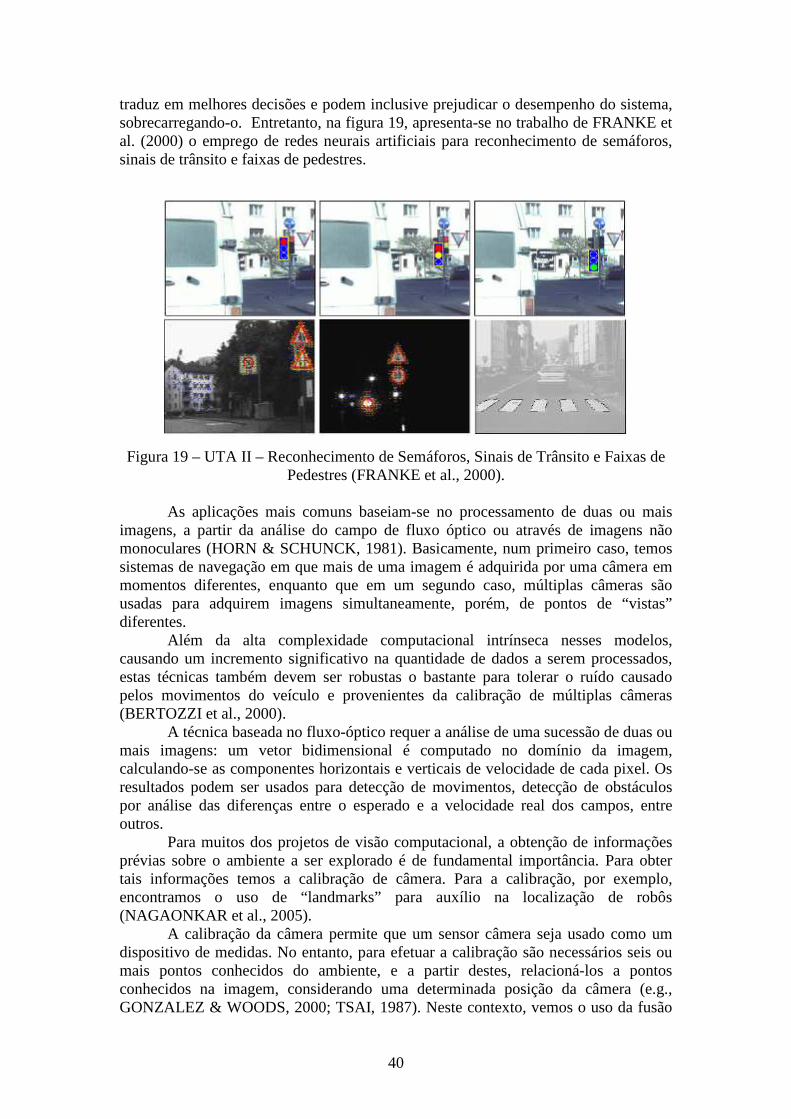
40
traduz em melhores decisões e podem inclusive prejudicar o desempenho do sistema, sobrecarregando-o. Entretanto, na figura 19, apresenta-se no trabalho de FRANKE et al. (2000) o emprego de redes neurais artificiais para reconhecimento de semáforos, sinais de trânsito e faixas de pedestres.
Figura 19 – UTA II – Reconhecimento de Semáforos, Sinais de Trânsito e Faixas de Pedestres (FRANKE et al., 2000).
As aplicações mais comuns baseiam-se no processamento de duas ou mais
imagens, a partir da análise do campo de fluxo óptico ou através de imagens não monoculares (HORN & SCHUNCK, 1981). Basicamente, num primeiro caso, temos sistemas de navegação em que mais de uma imagem é adquirida por uma câmera em momentos diferentes, enquanto que em um segundo caso, múltiplas câmeras são usadas para adquirem imagens simultaneamente, porém, de pontos de “vistas” diferentes.
Além da alta complexidade computacional intrínseca nesses modelos, causando um incremento significativo na quantidade de dados a serem processados, estas técnicas também devem ser robustas o bastante para tolerar o ruído causado pelos movimentos do veículo e provenientes da calibração de múltiplas câmeras (BERTOZZI et al., 2000).
A técnica baseada no fluxo-óptico requer a análise de uma sucessão de duas ou mais imagens: um vetor bidimensional é computado no domínio da imagem, calculando-se as componentes horizontais e verticais de velocidade de cada pixel. Os resultados podem ser usados para detecção de movimentos, detecção de obstáculos por análise das diferenças entre o esperado e a velocidade real dos campos, entre outros.
Para muitos dos projetos de visão computacional, a obtenção de informações prévias sobre o ambiente a ser explorado é de fundamental importância. Para obter tais informações temos a calibração de câmera. Para a calibração, por exemplo, encontramos o uso de “landmarks” para auxílio na localização de robôs (NAGAONKAR et al., 2005).
A calibração da câmera permite que um sensor câmera seja usado como um dispositivo de medidas. No entanto, para efetuar a calibração são necessários seis ou mais pontos conhecidos do ambiente, e a partir destes, relacioná-los a pontos conhecidos na imagem, considerando uma determinada posição da câmera (e.g., GONZALEZ & WOODS, 2000; TSAI, 1987). Neste contexto, vemos o uso da fusão
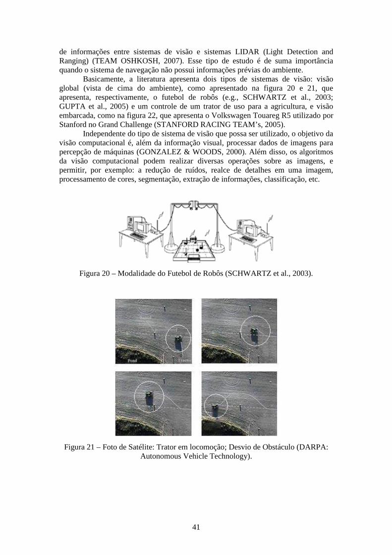
41
de informações entre sistemas de visão e sistemas LIDAR (Light Detection and Ranging) (TEAM OSHKOSH, 2007). Esse tipo de estudo é de suma importância quando o sistema de navegação não possui informações prévias do ambiente.
Basicamente, a literatura apresenta dois tipos de sistemas de visão: visão global (vista de cima do ambiente), como apresentado na figura 20 e 21, que apresenta, respectivamente, o futebol de robôs (e.g., SCHWARTZ et al., 2003; GUPTA et al., 2005) e um controle de um trator de uso para a agricultura, e visão embarcada, como na figura 22, que apresenta o Volkswagen Touareg R5 utilizado por Stanford no Grand Challenge (STANFORD RACING TEAM’s, 2005).
Independente do tipo de sistema de visão que possa ser utilizado, o objetivo da visão computacional é, além da informação visual, processar dados de imagens para percepção de máquinas (GONZALEZ & WOODS, 2000). Além disso, os algoritmos da visão computacional podem realizar diversas operações sobre as imagens, e permitir, por exemplo: a redução de ruídos, realce de detalhes em uma imagem, processamento de cores, segmentação, extração de informações, classificação, etc.
Figura 20 – Modalidade do Futebol de Robôs (SCHWARTZ et al., 2003).
Figura 21 – Foto de Satélite: Trator em locomoção; Desvio de Obstáculo (DARPA: Autonomous Vehicle Technology).
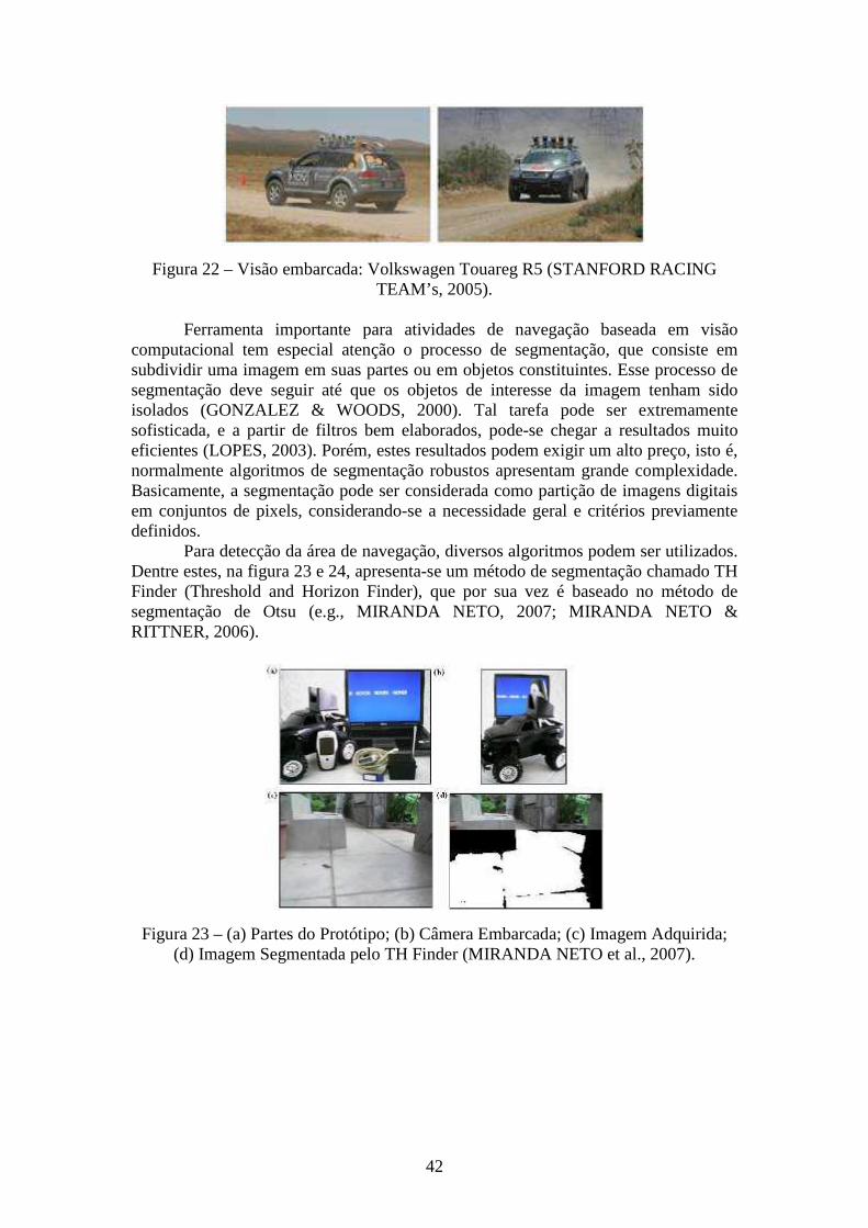
42
Figura 22 – Visão embarcada: Volkswagen Touareg R5 (STANFORD RACING TEAM’s, 2005).
Ferramenta importante para atividades de navegação baseada em visão
computacional tem especial atenção o processo de segmentação, que consiste em subdividir uma imagem em suas partes ou em objetos constituintes. Esse processo de segmentação deve seguir até que os objetos de interesse da imagem tenham sido isolados (GONZALEZ & WOODS, 2000). Tal tarefa pode ser extremamente sofisticada, e a partir de filtros bem elaborados, pode-se chegar a resultados muito eficientes (LOPES, 2003). Porém, estes resultados podem exigir um alto preço, isto é, normalmente algoritmos de segmentação robustos apresentam grande complexidade. Basicamente, a segmentação pode ser considerada como partição de imagens digitais em conjuntos de pixels, considerando-se a necessidade geral e critérios previamente definidos.
Para detecção da área de navegação, diversos algoritmos podem ser utilizados. Dentre estes, na figura 23 e 24, apresenta-se um método de segmentação chamado TH Finder (Threshold and Horizon Finder), que por sua vez é baseado no método de segmentação de Otsu (e.g., MIRANDA NETO, 2007; MIRANDA NETO & RITTNER, 2006).
Figura 23 – (a) Partes do Protótipo; (b) Câmera Embarcada; (c) Imagem Adquirida; (d) Imagem Segmentada pelo TH Finder (MIRANDA NETO et al., 2007).
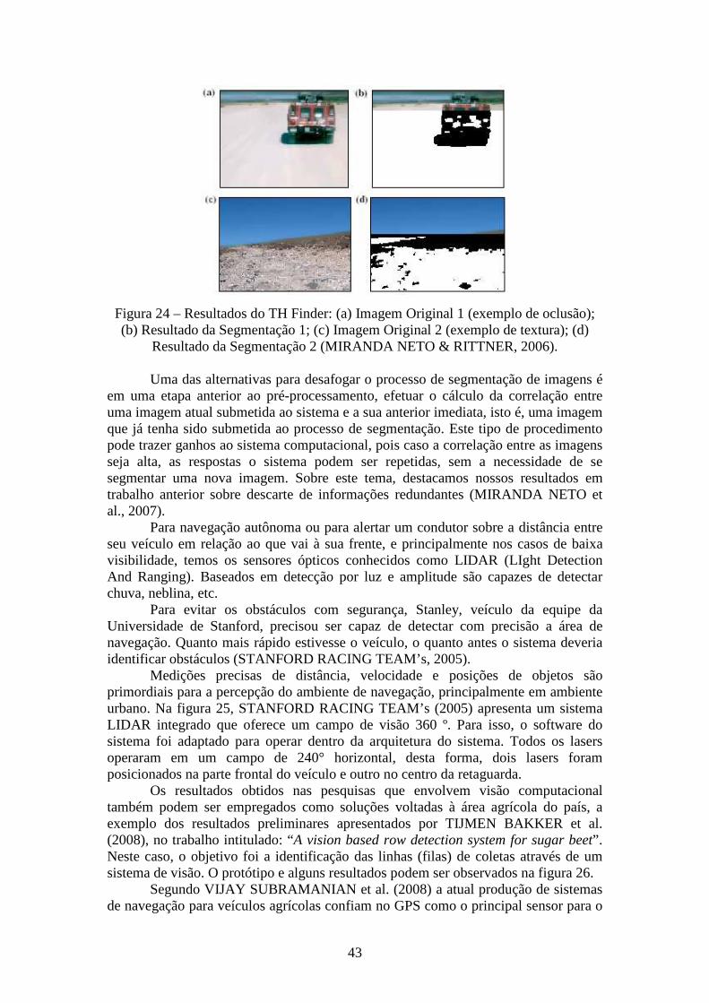
43
Figura 24 – Resultados do TH Finder: (a) Imagem Original 1 (exemplo de oclusão); (b) Resultado da Segmentação 1; (c) Imagem Original 2 (exemplo de textura); (d)
Resultado da Segmentação 2 (MIRANDA NETO & RITTNER, 2006). Uma das alternativas para desafogar o processo de segmentação de imagens é
em uma etapa anterior ao pré-processamento, efetuar o cálculo da correlação entre uma imagem atual submetida ao sistema e a sua anterior imediata, isto é, uma imagem que já tenha sido submetida ao processo de segmentação. Este tipo de procedimento pode trazer ganhos ao sistema computacional, pois caso a correlação entre as imagens seja alta, as respostas o sistema podem ser repetidas, sem a necessidade de se segmentar uma nova imagem. Sobre este tema, destacamos nossos resultados em trabalho anterior sobre descarte de informações redundantes (MIRANDA NETO et al., 2007).
Para navegação autônoma ou para alertar um condutor sobre a distância entre seu veículo em relação ao que vai à sua frente, e principalmente nos casos de baixa visibilidade, temos os sensores ópticos conhecidos como LIDAR (LIght Detection And Ranging). Baseados em detecção por luz e amplitude são capazes de detectar chuva, neblina, etc.
Para evitar os obstáculos com segurança, Stanley, veículo da equipe da Universidade de Stanford, precisou ser capaz de detectar com precisão a área de navegação. Quanto mais rápido estivesse o veículo, o quanto antes o sistema deveria identificar obstáculos (STANFORD RACING TEAM’s, 2005).
Medições precisas de distância, velocidade e posições de objetos são primordiais para a percepção do ambiente de navegação, principalmente em ambiente urbano. Na figura 25, STANFORD RACING TEAM’s (2005) apresenta um sistema LIDAR integrado que oferece um campo de visão 360 º. Para isso, o software do sistema foi adaptado para operar dentro da arquitetura do sistema. Todos os lasers operaram em um campo de 240° horizontal, desta forma, dois lasers foram posicionados na parte frontal do veículo e outro no centro da retaguarda.
Os resultados obtidos nas pesquisas que envolvem visão computacional também podem ser empregados como soluções voltadas à área agrícola do país, a exemplo dos resultados preliminares apresentados por TIJMEN BAKKER et al. (2008), no trabalho intitulado: “A vision based row detection system for sugar beet”. Neste caso, o objetivo foi a identificação das linhas (filas) de coletas através de um sistema de visão. O protótipo e alguns resultados podem ser observados na figura 26.
Segundo VIJAY SUBRAMANIAN et al. (2008) a atual produção de sistemas de navegação para veículos agrícolas confiam no GPS como o principal sensor para o
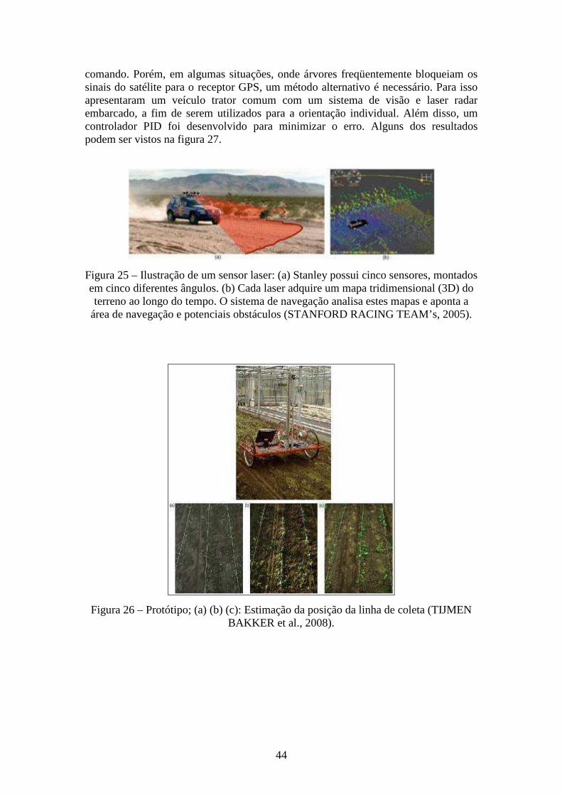
44
comando. Porém, em algumas situações, onde árvores freqüentemente bloqueiam os sinais do satélite para o receptor GPS, um método alternativo é necessário. Para isso apresentaram um veículo trator comum com um sistema de visão e laser radar embarcado, a fim de serem utilizados para a orientação individual. Além disso, um controlador PID foi desenvolvido para minimizar o erro. Alguns dos resultados podem ser vistos na figura 27.
Figura 25 – Ilustração de um sensor laser: (a) Stanley possui cinco sensores, montados em cinco diferentes ângulos. (b) Cada laser adquire um mapa tridimensional (3D) do terreno ao longo do tempo. O sistema de navegação analisa estes mapas e aponta a
área de navegação e potenciais obstáculos (STANFORD RACING TEAM’s, 2005).
Figura 26 – Protótipo; (a) (b) (c): Estimação da posição da linha de coleta (TIJMEN BAKKER et al., 2008).
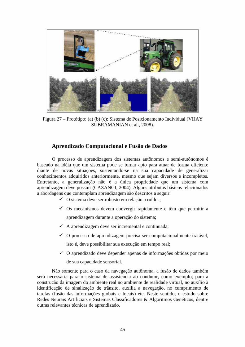
45
Figura 27 – Protótipo; (a) (b) (c): Sistema de Posicionamento Individual (VIJAY SUBRAMANIAN et al., 2008).
Aprendizado Computacional e Fusão de Dados
O processo de aprendizagem dos sistemas autônomos e semi-autônomos é
baseado na idéia que um sistema pode se tornar apto para atuar de forma eficiente diante de novas situações, sustentando-se na sua capacidade de generalizar conhecimentos adquiridos anteriormente, mesmo que sejam diversos e incompletos. Entretanto, a generalização não é a única propriedade que um sistema com aprendizagem deve possuir (CAZANGI, 2004). Alguns atributos básicos relacionados a abordagens que contemplam aprendizagem são descritos a seguir:
� O sistema deve ser robusto em relação a ruídos;
� Os mecanismos devem convergir rapidamente e têm que permitir a
aprendizagem durante a operação do sistema;
� A aprendizagem deve ser incremental e continuada;
� O processo de aprendizagem precisa ser computacionalmente tratável,
isto é, deve possibilitar sua execução em tempo real;
� O aprendizado deve depender apenas de informações obtidas por meio
de sua capacidade sensorial.
Não somente para o caso da navegação autônoma, a fusão de dados também será necessária para o sistema de assistência ao condutor, como exemplo, para a construção da imagem do ambiente real no ambiente de realidade virtual, no auxílio à identificação de sinalização de trânsito, auxilia a navegação, no cumprimento de tarefas (fusão das informações globais e locais) etc. Neste sentido, o estudo sobre Redes Neurais Artificiais e Sistemas Classificadores & Algoritmos Genéticos, dentre outras relevantes técnicas de aprendizado.
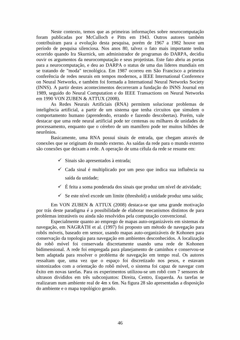
46
Neste contexto, temos que as primeiras informações sobre neurocomputação foram publicadas por McCulloch e Pitts em 1943. Outros autores também contribuíram para a evolução desta pesquisa, porém de 1967 a 1982 houve um período de pesquisa silenciosa. Nos anos 80, talvez o fato mais importante tenha ocorrido quando Ira Skurnick, um administrador de programas do DARPA, decidiu ouvir os argumentos da neurocomputação e seus projetistas. Este fato abriu as portas para a neurocomputação, e deu ao DARPA o status de uma das líderes mundiais em se tratando de "moda" tecnológica. Em 1987 ocorreu em São Francisco a primeira conferência de redes neurais em tempos modernos, a IEEE International Conference on Neural Networks, e também foi formada a International Neural Networks Society (INNS). A partir destes acontecimentos decorreram a fundação do INNS Journal em 1989, seguido do Neural Computation e do IEEE Transactions on Neural Networks em 1990 VON ZUBEN & ATTUX (2008).
As Redes Neurais Artificiais (RNA) permitem solucionar problemas de inteligência artificial, a partir de um sistema que tenha circuitos que simulem o comportamento humano (aprendendo, errando e fazendo descobertas). Porém, vale destacar que uma rede neural artificial pode ter centenas ou milhares de unidades de processamento, enquanto que o cérebro de um mamífero pode ter muitos bilhões de neurônios.
Basicamente, uma RNA possui sinais de entrada, que chegam através de conexões que se originam do mundo externo. As saídas da rede para o mundo externo são conexões que deixam a rede. A operação de uma célula da rede se resume em:
� Sinais são apresentados à entrada;
� Cada sinal é multiplicado por um peso que indica sua influência na
saída da unidade;
� É feita a soma ponderada dos sinais que produz um nível de atividade;
� Se este nível excede um limite (threshold) a unidade produz uma saída;
Em VON ZUBEN & ATTUX (2008) destaca-se que uma grande motivação por trás deste paradigma é a possibilidade de elaborar mecanismos distintos de para problemas intratáveis ou ainda não resolvidos pela computação convencional.
Especialmente quanto ao emprego de mapas auto-organizáveis em sistemas de navegação, em NAGRATH et al. (1997) foi proposto um método de navegação para robôs móveis, baseado em sensor, usando mapas auto-organizáveis de Kohonen para conservação da topologia para navegação em ambientes desconhecidos. A localização do robô móvel foi conservada discretamente usando uma rede de Kohonen bidimensional. A rede foi empregada para planejamento de caminhos e conservou-se bem adaptada para resolver o problema de navegação em tempo real. Os autores ressaltam que, uma vez que o espaço foi discretizado nos pesos, e estavam sintonizados com a orientação do robô móvel, o sistema foi capaz de navegar com êxito em novas tarefas. Para os experimentos utilizou-se um robô com 7 sensores de ultrason divididos em três subconjuntos: Direita, Centro, Esquerda. As tarefas se realizaram num ambiente real de 4m x 6m. Na figura 28 são apresentadas a disposição do ambiente e o mapa topológico gerado.
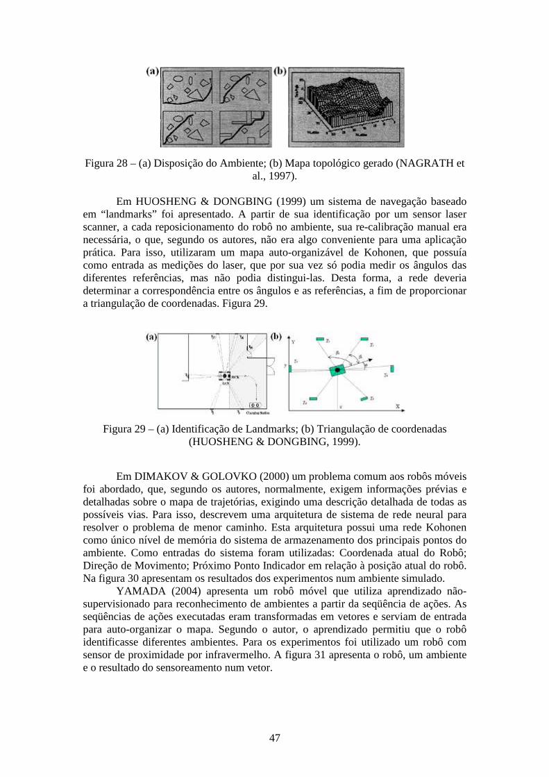
47
Figura 28 – (a) Disposição do Ambiente; (b) Mapa topológico gerado (NAGRATH et al., 1997).
Em HUOSHENG & DONGBING (1999) um sistema de navegação baseado
em “landmarks” foi apresentado. A partir de sua identificação por um sensor laser scanner, a cada reposicionamento do robô no ambiente, sua re-calibração manual era necessária, o que, segundo os autores, não era algo conveniente para uma aplicação prática. Para isso, utilizaram um mapa auto-organizável de Kohonen, que possuía como entrada as medições do laser, que por sua vez só podia medir os ângulos das diferentes referências, mas não podia distingui-las. Desta forma, a rede deveria determinar a correspondência entre os ângulos e as referências, a fim de proporcionar a triangulação de coordenadas. Figura 29.
Figura 29 – (a) Identificação de Landmarks; (b) Triangulação de coordenadas (HUOSHENG & DONGBING, 1999).
Em DIMAKOV & GOLOVKO (2000) um problema comum aos robôs móveis foi abordado, que, segundo os autores, normalmente, exigem informações prévias e detalhadas sobre o mapa de trajetórias, exigindo uma descrição detalhada de todas as possíveis vias. Para isso, descrevem uma arquitetura de sistema de rede neural para resolver o problema de menor caminho. Esta arquitetura possui uma rede Kohonen como único nível de memória do sistema de armazenamento dos principais pontos do ambiente. Como entradas do sistema foram utilizadas: Coordenada atual do Robô; Direção de Movimento; Próximo Ponto Indicador em relação à posição atual do robô. Na figura 30 apresentam os resultados dos experimentos num ambiente simulado.
YAMADA (2004) apresenta um robô móvel que utiliza aprendizado não-supervisionado para reconhecimento de ambientes a partir da seqüência de ações. As seqüências de ações executadas eram transformadas em vetores e serviam de entrada para auto-organizar o mapa. Segundo o autor, o aprendizado permitiu que o robô identificasse diferentes ambientes. Para os experimentos foi utilizado um robô com sensor de proximidade por infravermelho. A figura 31 apresenta o robô, um ambiente e o resultado do sensoreamento num vetor.
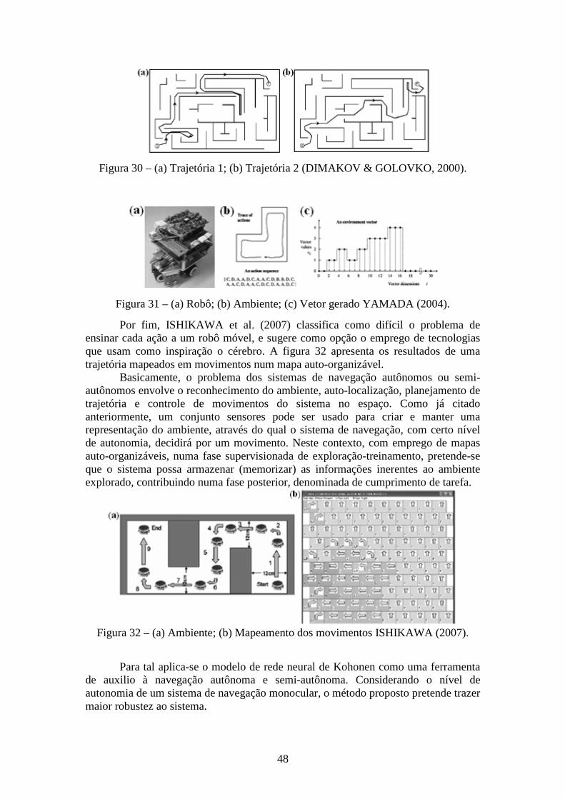
48
Figura 30 – (a) Trajetória 1; (b) Trajetória 2 (DIMAKOV & GOLOVKO, 2000).
Figura 31 – (a) Robô; (b) Ambiente; (c) Vetor gerado YAMADA (2004).
Por fim, ISHIKAWA et al. (2007) classifica como difícil o problema de ensinar cada ação a um robô móvel, e sugere como opção o emprego de tecnologias que usam como inspiração o cérebro. A figura 32 apresenta os resultados de uma trajetória mapeados em movimentos num mapa auto-organizável.
Basicamente, o problema dos sistemas de navegação autônomos ou semi-autônomos envolve o reconhecimento do ambiente, auto-localização, planejamento de trajetória e controle de movimentos do sistema no espaço. Como já citado anteriormente, um conjunto sensores pode ser usado para criar e manter uma representação do ambiente, através do qual o sistema de navegação, com certo nível de autonomia, decidirá por um movimento. Neste contexto, com emprego de mapas auto-organizáveis, numa fase supervisionada de exploração-treinamento, pretende-se que o sistema possa armazenar (memorizar) as informações inerentes ao ambiente explorado, contribuindo numa fase posterior, denominada de cumprimento de tarefa.
Figura 32 – (a) Ambiente; (b) Mapeamento dos movimentos ISHIKAWA (2007).
Para tal aplica-se o modelo de rede neural de Kohonen como uma ferramenta
de auxilio à navegação autônoma e semi-autônoma. Considerando o nível de autonomia de um sistema de navegação monocular, o método proposto pretende trazer maior robustez ao sistema.
49
Rede ou Interconexão entre Dispositivos Móveis
Concebidos para interconexão entre dispositivos e também para controle em automóveis, surgem as redes de comunicação e diferentes protocolos para interface entre dispositivos. Como exemplo, as Redes Ad Hoc e também os protocolos CAN (Controller Area Network).
Seja para minimizar a relação desempenho-peso, principalmente para projetos experimentais, para veículos ou robôs de pequeno porte, ou ainda para os casos em que haja dificuldades em embarcar todo o hardware necessário, ou mesmo seguindo uma determinada estratégia de ação, diversos tipos de arquitetura de sistema distribuído e/ou cliente-servidor podem ser empregadas. Assim, algumas das tarefas como armazenamento e processamento de informações, podem ser compartilhadas (entre robôs ou veículos próximos) e/ou atribuídas a uma máquina servidora remota mais potente. Esse tipo de solução também permite o compartilhamento da base de dados, além de operações em cooperação. Com isto, informações adquiridas a partir da exploração de ambientes por determinado agente podem ser aproveitadas por outro (MIRANDA NETO, 2007).
Segundo TANENBAUM & VAN STEEN (2002) um sistema distribuído baseia-se em uma coleção de computadores independentes que se apresentam ao usuário como um sistema único e permite o compartilhamento dos recursos do sistema: hardware, software e dados. Assim, incluindo recursos das redes de computadores, um sistema de processamento paralelo interliga vários nós de processamento, por exemplo: computadores individuais não necessariamente homogêneos, de maneira que um processo de grande consumo seja executado no nó mais disponível, ou mesmo subdividido por vários nós. Desta forma, uma tarefa qualquer pode se dividir em várias subtarefas executadas em paralelo. Assim, a computação distribuída consiste em adicionar o poder computacional de diversos computadores ou em diferentes núcleos de um mesmo computador.
Atualmente processadores utilizam mais de um núcleo de processamento. Investindo em arquiteturas paralelas, a utilização da programação “multi-thread” consiste em colocar vários fluxos de execução (threads) dentro de um único processo. Desta forma, cresce o apelo pela programação paralela, onde o desenvolvimento de programas depende do tipo de arquitetura (OLIVEIRA et al., 2004). Além disso, tal abstração (sistemas multicamadas), além de permitir a implementação em uma arquitetura cliente-servidor e de sistema distribuído, está mais próxima às características da nova geração de computadores multiprocessados, e da estrutura dos sistemas operacionais (MIRANDA NETO & RITTNER, 2006). Outro exemplo é apresentado no projeto UTA (Mercedes-Benz E-class) onde a programação distribuída é aplicada à assistência ao condutor (e.g., GÖRZIG, 2001; FRANKE et al., 2000).
Usando uma rede ad hoc, que não possui uma topologia predeterminada, e nem dispõe de controle centralizado, seus nós da rede se comunicam sem a necessidade de uma conexão física, onde alguns dos dispositivos da rede apenas fazem parte da mesma durante a sessão de comunicação, ou, enquanto estão a uma certa proximidade do restante da rede. Nessa rede, cada nó atua tanto como roteador quanto como um host. Dessa forma, todos os nós individualmente participam da descoberta e manutenção de rotas para outros nós. Com a ausência de infra-estrutura fixa, a responsabilidade por organizar e controlar a rede é distribuída entre os próprios terminais (PERKINS & ROYER (1999).
Utilizado pela equipe TerraMax no Urban Challenge TEAM OSHKOSH (2007), e principalmente aplicados a implementos agrícolas no Brasil, o CAN surgiu
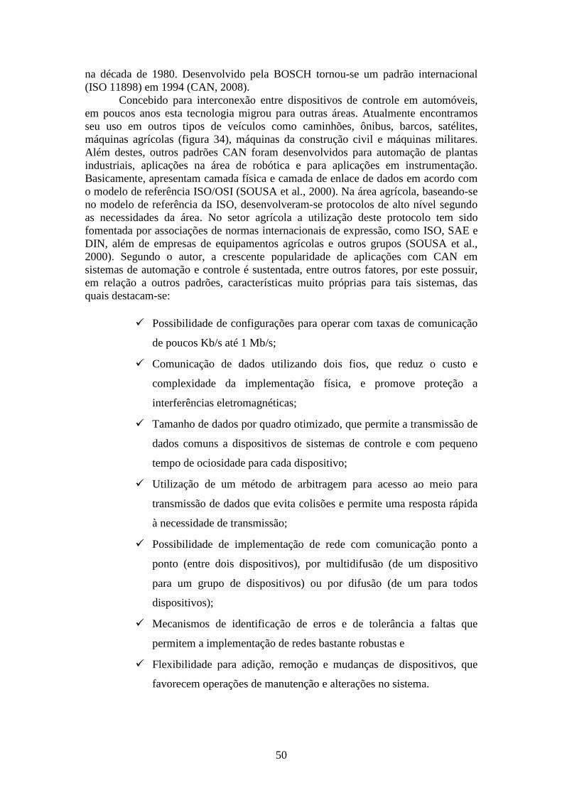
50
na década de 1980. Desenvolvido pela BOSCH tornou-se um padrão internacional (ISO 11898) em 1994 (CAN, 2008).
Concebido para interconexão entre dispositivos de controle em automóveis, em poucos anos esta tecnologia migrou para outras áreas. Atualmente encontramos seu uso em outros tipos de veículos como caminhões, ônibus, barcos, satélites, máquinas agrícolas (figura 34), máquinas da construção civil e máquinas militares. Além destes, outros padrões CAN foram desenvolvidos para automação de plantas industriais, aplicações na área de robótica e para aplicações em instrumentação. Basicamente, apresentam camada física e camada de enlace de dados em acordo com o modelo de referência ISO/OSI (SOUSA et al., 2000). Na área agrícola, baseando-se no modelo de referência da ISO, desenvolveram-se protocolos de alto nível segundo as necessidades da área. No setor agrícola a utilização deste protocolo tem sido fomentada por associações de normas internacionais de expressão, como ISO, SAE e DIN, além de empresas de equipamentos agrícolas e outros grupos (SOUSA et al., 2000). Segundo o autor, a crescente popularidade de aplicações com CAN em sistemas de automação e controle é sustentada, entre outros fatores, por este possuir, em relação a outros padrões, características muito próprias para tais sistemas, das quais destacam-se:
� Possibilidade de configurações para operar com taxas de comunicação
de poucos Kb/s até 1 Mb/s;
� Comunicação de dados utilizando dois fios, que reduz o custo e
complexidade da implementação física, e promove proteção a
interferências eletromagnéticas;
� Tamanho de dados por quadro otimizado, que permite a transmissão de
dados comuns a dispositivos de sistemas de controle e com pequeno
tempo de ociosidade para cada dispositivo;
� Utilização de um método de arbitragem para acesso ao meio para
transmissão de dados que evita colisões e permite uma resposta rápida
à necessidade de transmissão;
� Possibilidade de implementação de rede com comunicação ponto a
ponto (entre dois dispositivos), por multidifusão (de um dispositivo
para um grupo de dispositivos) ou por difusão (de um para todos
dispositivos);
� Mecanismos de identificação de erros e de tolerância a faltas que
permitem a implementação de redes bastante robustas e
� Flexibilidade para adição, remoção e mudanças de dispositivos, que
favorecem operações de manutenção e alterações no sistema.
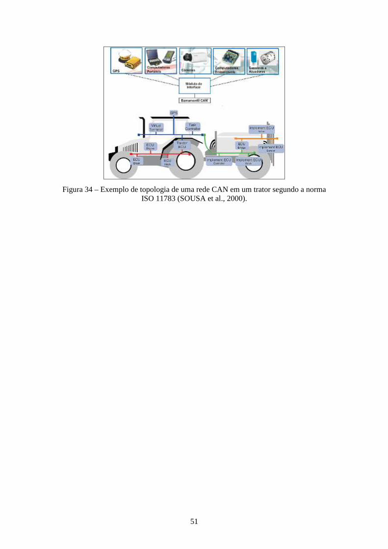
51
Figura 34 – Exemplo de topologia de uma rede CAN em um trator segundo a norma ISO 11783 (SOUSA et al., 2000).
52
Comportamento Básico e Critérios de Avaliação Técnica Os veículos que participaram do desafio do DARPA utilizaram um grande
conjunto de dispositivos para permitir a navegação, dentre os quais se podem citar câmeras de vídeo, LASER (LIDAR – Light Detection and Ranging), sistemas de navegação inercial, GPS e pontos de passagem. As plataformas computacionais empregadas pelas várias equipes foram Linux e Windows, com uso de C, C++, Java, LabVIEW. Como recursos sensoriais desta proposta pretende-se, inicialmente, utilizar câmeras de vídeo, LASER e GPS.
Na elaboração do projeto pretende-se definir seu comportamento básico através de Critérios de Avaliação Técnica (CAT), figura 35. De acordo com o aumento do grau desejado de autonomia do veículo, a complexidade dos critérios a serem avaliados também aumenta, bem como o tempo e os recursos necessários para a implantação do projeto. Para a proposta apresentada, serão tratados os critérios relativos a um Sistema de Navegação Autônomo e Semi-Autônomo.
Figura 35 – Critérios de Avaliação Técnica.
Os critérios de avaliação técnica estão organizados em cinco conjuntos com
suas respectivas subdivisões, que aumentam sua complexidade de forma progressiva. Os critérios para um veículo com Sistema de Navegação Autônomo são Segurança, Navegação Básica, Tráfego Básico, Navegação Avançada e Tráfego Avançado.
De uma forma geral, os critérios de avaliação técnica de um Sistema de Assistência ao Condutor são semelhantes aos citados acima, exceto que para o SAC haverá apenas alertas para o condutor, não existindo atuação autônoma no comportamento do veículo. Quem vai atuar e gerir o comportamento do veículo será o piloto após processar os alertas recebidos.
Assim, para iniciar o projeto, são propostas as tarefas de emissão de alertas para garantir a dirigibilidade do veículo em linha reta ou curva, permitir o estacionamento do veículo e a realização do deslocamento em itinerário preestabelecido. Tais alertas serão apresentados em um sistema de realidade virtual
53
não-imersiva. O ambiente de testes do Sistema de Navegação tem que ser previamente preparado, particularmente em relação à marcação de faixas de rolamento, posição de pontos de passagem, limites de estacionamento, delimitação das zonas, preparação de obstáculos, sinalização horizontal e vertical de trânsito.
Considerando que um SAC é um sistema em parte autônomo, os critérios de avaliação técnica serão apresentados abaixo, porém para um Sistema de Navegação Autônomo. Deve-se então considerar que todo critério de avaliação que indique inferência ao veículo deva ser convertido num sistema de alerta ao condutor. Para o caso do primeiro estágio, isto é, quando aplicados a robôs, será possível a inferência ao mesmo, o que não isentará a necessidade da conversão num sistema de alerta ao condutor.
Logo após cada apresentação de cada item dos critérios de avaliação técnica, a seguir, para um Sistema de Navegação Autônomo, será dado enfoque ao essencial a que se pretende com esta proposta de pesquisa, visto que, dependendo da plataforma robótica selecionada, será permitido que certos controles sejam implementados. Cada módulo apresentado abaixo poderá ser encontrado na figura 9.
Comportamento Básico para um Sistema de Navegação Autônomo
Segurança Deve existir um dispositivo de parada eletrônica de emergência, denominado
E-stop, que deve ter a capacidade de realizar frenagem de emergência do veículo. O veículo deve parar completamente, de modo suave e controlado, em uma distância, pré-determinada oportunamente, após ativação do E-stop.
Navegação Básica Este critério é composto por um conjunto de atividades básicas de navegação,
definidas em 12 subitens. 1. Preparação para Deslocar O veículo está em modo autônomo e pronto para começar o deslocamento até
5 minutos após o recebimento do Arquivo de Dados da Missão (ADM). 2. Início da Missão O veículo deve seguir os pontos de passagem do ADM. 3. Pontos de Passagem O pára-choque do veículo deve passar sobre cada ponto de passagem no ADM
na faixa correta e na seqüência prevista pelo ADM. Os pontos de passagem estarão marcados na terra/pavimento.
4. Permanência na Faixa O veículo deve permanecer com todas as rodas na sua faixa de rolamento
durante todo o trajeto, exceto quando realizar uma manobra legal de trânsito, como por exemplo, virar à direita ou manobrar para evitar um obstáculo.
5. Limites de Velocidade O veículo deve seguir os limites de velocidade, máximos e mínimos. Quando
o veículo tiver que parar devido a um obstáculo, isso não será entendido como violação desse critério.
6. Atraso em Excesso O veículo deve obedecer a critérios de excesso de atraso na rota, subordinado
àquele responsável pela condução segura (prevê a ocorrência de acidentes e/ou colisões).
54
7. Colisões O veículo deve evitar colisões e quase-colisões durante todo o percurso. Este é
o principal critério a ser observado. O veículo deve continuamente monitorar o caminho à frente buscando identificar veículos e obstáculos a fim de evitar colisões. O veículo não deve assumir que o comportamento de outro veículo é completamente previsível.
8. Faixa de Pedestre/Linha de Retenção O veículo deve parar antes da Faixa de forma tal que o pára-choque do veículo
deve ficar a uma distância segura do meio da Faixa. O veículo não deve parar sobre a faixa ou obstruir, ainda que parcialmente, um cruzamento.
9. Separação dos Veículos O veículo deve manter um espaçamento mínimo dos lados e da traseira de
todos os veículos e obstáculos em todas as áreas do percurso. Em áreas de segurança, o veículo deve manter uma distância mínima do veículo da frente. Nas demais aéreas do percurso, o veículo deve manter uma separação de um veículo de comprimento, sendo um veículo a separação mínima. As áreas de segurança incluem áreas de cruzamentos e distância da Faixa de Pedestre/Faixa de Parada; áreas de estacionamento e campos de obstáculos.
10. Início de Ultrapassagem O veículo deve manter uma distância de um veículo de separação entre o
veículo ou obstáculo parado à sua frente antes de iniciar a ultrapassagem do mesmo. 11. Retorno à Faixa Após Ultrapassagem O veículo deve retornar à faixa prevista em um intervalo de distância de 1 a 4
vezes o tamanho do veículo ultrapassante para completar a manobra. 12. Retorno O veículo deve ter habilidade para realizar retorno (curva em U), observando-
se a largura em comprimento e extensão. Tráfego Básico Este critério é composto por um conjunto de atividades básicas de tráfego,
definidas em 4 subitens. 1. Navegação Básica O veículo deve satisfazer todos os critérios de navegação básica. 2. Precedência de Intersecção O veículo deve respeitar a ordem de precedência nas intersecções. A regra
básica de precedência em uma intersecção é que o primeiro veículo a parar na faixa é o primeiro veículo a sair. Ao veículo entrar na intersecção, ele deve monitorar continuamente os outros veículos e o caminho à frente para eliminar a possibilidade de colisão.
3. Distância Mínima a Seguir O veículo deve manter a distância de veículo à frente quando em movimento
no tráfego. Critério é consistente quando aplicado ao tráfego em movimento, com diferentes distâncias de separação no tráfego e em áreas de segurança.
4. Comportamento na Fila O veículo deve exibir comportamento adequado quando em uma fila de
veículos parados, sempre mantendo a distância para o veículo à frente. Esta distância deve variar de um a dois comprimentos do próprio veículo.
55
Navegação Avançada Este critério é composto por um conjunto de atividades avançadas de
navegação, definidas em 6 subitens. 1. Tráfego Básico O veículo deve satisfazer todos os critérios de tráfego básico. 2. Campo de Obstáculos O veículo deve ter capacidade para lidar com campo de obstáculos de forma
eficiente e segura. O veículo deve ser capaz de operar em uma zona desestruturada onde não há definição de faixas (sinalização horizontal). Essas zonas podem ou não ser pavimentadas ou ter marcas no pavimento. O veículo deve ter capacidade de avaliar se o declive à montante ou à jusante é diferente de uma configuração semelhante a uma escada, evitando confundir, por exemplo, com algumas entradas de prédios que possuem esta característica. O veículo deve evitar colisões e manter a distância de segurança do veículo/obstáculo à frente. É possível haver obstáculos estáticos (árvores, pedras) e dinâmicos (veículos). Para evitar colisões, uma vez detectado deslocamento de outro veículo em sentido contrário, o veículo deve adotar a regra geral de desviar à direita e em seguida prosseguir em frente, consultando antes se essa possibilidade não oferece riscos adicionais.
3. Estacionamento O veículo deve exibir comportamento adequado para realizar estacionamento.
Para isso, deve entrar na vaga prevista de frente, passar por um ponto de entrada, passar por um segundo ponto de controle, ambos marcados no pavimento, e estacionar observando os limites da vaga. Para sair, deve observar o mesmo, sendo que a manobra será realizada à ré. A vaga estará delimitada por faixas no pavimento. Cuidado especial deve ser atribuído àqueles espaços onde há fosso logo à frente da vaga do estacionamento, à semelhança de estacionamentos localizados em prédios-estacionamento.
4. Re-planejamento Dinâmico O veículo deve ser capaz de atingir os pontos de passagem previstos mesmo
quando as vias estiverem bloqueadas. O bloqueio de vias não será previsto no Arquivo de Definição de Rota (ADR). A rota pode ser bloqueada por veículos estacionados, ouriços e linha de barris. Sempre haverá uma rota alternativa para permitir o prosseguimento da missão. O veículo deve se manter na via e fazer a meia-volta, planejando uma rota alternativa. O emprego de ré é limitado à distância de 3 comprimentos do veículo.
5. Seguimento de Via O veículo deve ter habilidade para navegar em vias com pontos de passagem
esparsos e permanecer na faixa de rolamento seguindo os limites da via, da própria faixa ou usar outra técnica de sensoriamento para esse fim. O veículo deve ainda poder realizar curva de 90º sem necessitar de um conjunto denso de pontos de passagem.
6. GPS O veículo não deve demonstrar retardo excessivo ou abandonar a faixa de
rolamento devido a perda intermitente de sinais de navegação do GPS. Uma unidade de navegação inercial ou outra técnica deve ser usada para permitir que o veículo prossiga com segurança na rota com faixa, possivelmente em velocidade reduzida, até que o sinal do GPS seja restaurado.
56
Tráfego Avançado Este critério é composto por um conjunto de atividades avançadas de tráfego,
definidas em 9 subitens. 1. Navegação Avançada O veículo deve satisfazer todos os critérios de navegação avançada. 2. Fusão de Tráfego O veículo deve sempre entrar no movimento do tráfego quando houver um
tempo seguro antes da chegada do próximo veículo. O veículo pode se deslocar em um intervalo de tempo seguro quando as condições assim permitirem. O veículo que entra no tráfego deve acelerar de forma tal que o veículo que virá atrás consiga manter distância de segurança e velocidade constante.
3. Separação de Veículos durante a Fusão de Tráfego O veículo deve ser capaz de entrar em faixa de rolamento entre dois veículos
em um tráfego em movimento. O veículo deve manter uma distância segura do veículo à frente e o veículo que vem atrás não deve necessitar reduzir ou parar seu deslocamento.
4. Curva à Esquerda O veículo deve permitir virar à esquerda cruzando uma faixa de rolamento que
tem tráfego em sentido contrário ao seu deslocamento quando houver um tempo seguro para outro veículo que vem em sentido oposto. Se as condições permitirem, o veículo pode completar a curva num tempo indeterminado, obedecendo a regras prévias.
5. Separação de Veículos Durante Curva à Esquerda Após fazer uma curva à esquerda e cruzar uma faixa de rolamento, o veículo
deve manter a distância de segurança de pelo menos 2 veículos de comprimento para evitar colisões, sem causar redução ou parada no tráfego.
6. Zonas O veículo deve poder navegar em zonas de forma efetiva e segura na presença
de tráfego em movimento ou outros obstáculos. O tráfego em movimento em zonas cria um desafio tendo em vista a ausência de faixas de tráfego.
7. Parada de Emergência O veículo deve parar de forma completa e segura para evitar colisão quando
um obstáculo se move subitamente na faixa de rolamento. O tempo de antecipação deve obedecer a uma margem segura de tempo. Assim, para um veículo em movimento, o sistema deve ser capaz de parar com segurança quando surgir um obstáculo à frente.
8. Direção Defensiva O veículo deve realizar manobras de direção defensiva para evitar colisões
iminentes e manter a distância entre veículos. O veículo deve lidar com situações de tráfego com velocidade de aproximação segura. O veículo deve ser capaz de detectar o veículo que se aproxima, reconhecer a ameaça e realizar manobra evasiva para evitar a colisão.
9. Bloqueio de Tráfego O veículo deve ser capaz de realizar manobras para poder prosseguir e evitar
colisão em uma intersecção parcialmente bloqueada. Em uma intersecção na qual ocorra tal bloqueio parcial, o veículo deve esperar um tempo seguro para estabelecer ordem de precedência antes de prosseguir no cruzamento e redefinir a nova rota para atingir o próximo ponto de passagem.
57
Arquitetura de hardware e sistemas Considerando o veículo ou robô como plataforma de desenvolvimento, chama-
se especial atenção aos itens a seguir:
� Item A – Projeto de Hardware (Computadores; Sensores): sua ênfase
está para aplicação num veículo real;
� Item B – Arquitetura do Sistema: aplica-se aos dois estágios da
proposta;
Para o primeiro estágio da pesquisa, pretende-se a utilização de robôs de menor escala, a exemplo das plataformas robóticas, com grande aceitação junto à comunidade científica. Além do tamanho reduzido, o robô pode ser acompanhado de diversos equipamentos adicionais, por exemplo: cordão umbilical, transmissor/receptor de rádio para comunicação, câmera de vídeo para estudos de visão embarcada, etc. Também, pode ser controlado através de softwares LabView e Matlab, ou ainda diretamente através de palavras de controle enviadas à porta de um computador, sem a necessidade de aquisição de nenhum software adicional.
Projeto de Hardware Computadores
Para suportar os Sistemas de Visão deverão ser utilizados computadores pessoais PC Quad-Core Intel, estruturados de forma sincronizada e hierarquizada, e adequados ao ambiente do veículo. A experiência de equipes que participaram de outras edições dos Darpa Challenge mostrou que normalmente é empregado um computador para cada sistema/sensor. Dessa forma, a previsão inicial é de no mínimo um e no máximo 4 (quatro) PC para o Sistema de Visão (trinocular, close range stereo, visão traseira, visão lateral). A quantidade exata de máquinas será determinada após os testes e ensaios da integração dos sistemas/sensores e a definição do escopo do projeto.
Sensores Sensores são componentes extremamente importantes para a navegação.
Inicialmente, há previsão de um Sistema de Visão e Laser. Sistema de Visão O Sistema de Visão (SV) tem por finalidade permitir que o sistema
“enxergue” o meio exterior. Pretende-se que seja composto por Seleção de Câmera de Vídeo e o Sistema Laser.
Sistema LIDAR O sistema LIDAR tem por finalidade realizar medidas precisas de distância,
velocidade e detecção de objetos. Sua aquisição/utilização será objeto de análise no decorrer do projeto.
Arquitetura do Sistema
A arquitetura do sistema é composta de Arquitetura Lógica e Implantação da Arquitetura, abordadas a seguir.
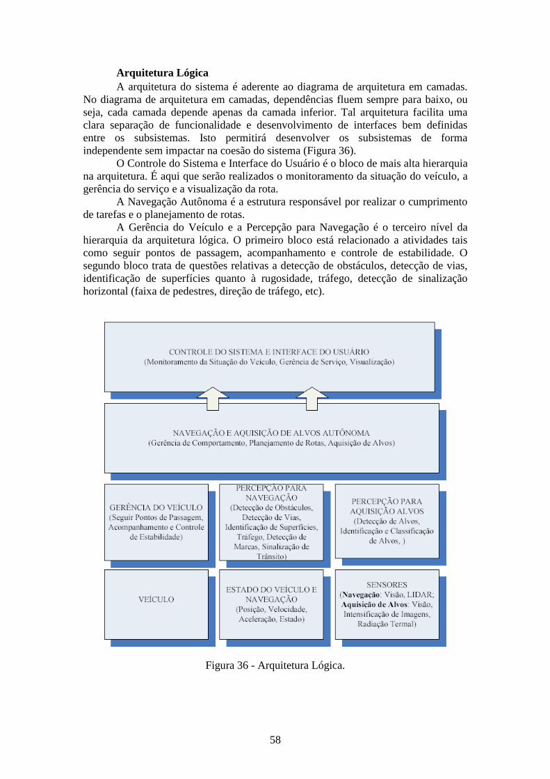
58
Arquitetura Lógica A arquitetura do sistema é aderente ao diagrama de arquitetura em camadas.
No diagrama de arquitetura em camadas, dependências fluem sempre para baixo, ou seja, cada camada depende apenas da camada inferior. Tal arquitetura facilita uma clara separação de funcionalidade e desenvolvimento de interfaces bem definidas entre os subsistemas. Isto permitirá desenvolver os subsistemas de forma independente sem impactar na coesão do sistema (Figura 36).
O Controle do Sistema e Interface do Usuário é o bloco de mais alta hierarquia na arquitetura. É aqui que serão realizados o monitoramento da situação do veículo, a gerência do serviço e a visualização da rota.
A Navegação Autônoma é a estrutura responsável por realizar o cumprimento de tarefas e o planejamento de rotas.
A Gerência do Veículo e a Percepção para Navegação é o terceiro nível da hierarquia da arquitetura lógica. O primeiro bloco está relacionado a atividades tais como seguir pontos de passagem, acompanhamento e controle de estabilidade. O segundo bloco trata de questões relativas a detecção de obstáculos, detecção de vias, identificação de superfícies quanto à rugosidade, tráfego, detecção de sinalização horizontal (faixa de pedestres, direção de tráfego, etc).
Figura 36 - Arquitetura Lógica.
59
Arquitetura de Implantação A arquitetura de implantação é dividida em dois grandes blocos: Serviços do
Sistema e Serviços Autônomos. O primeiro engloba diagnóstico veicular sistêmico, serviço de controle e configuração e visualização. O segundo bloco abrange serviços de sensoriamento, serviços de comportamento autônomo, serviços de percepção e serviços de gerenciamento do veículo.
1. Serviços Autônomos Serviços Autônomos é a parte do sistema responsável por obter informações
do ambiente e do veículo. É composto por Gerenciador de Veículo Autônomo, Sistema de Navegação, Servidor de Estado, Servidor de Percepção, Servidor de Navegação, e diversos sensores.
2. Gerenciador de Veículo Autônomo O Gerenciador de Veículo Autônomo (GVA) gerencia o alto nível de operação
do sistema. É responsável por realizar o planejamento de rota, planejamento de trajetória e gerência de comportamento. O GVA recebe atualizações de percepção do Servidor de Percepção de Navegação (SPN) e usa esta informação para acompanhar o estado atual do veículo e determinar seu comportamento. O GVA monitora de forma contínua os obstáculos percebidos, a informação de limite de faixa de rolamento e distribui planos de trajetória revisados.
3. Servidor de Estado O Servidor de Estado (SE) monitora, gerencia e registra todas as condições
dos modos do sistema no controle de baixo nível. O SE detecta quaisquer falhas, tenta fazer a recuperação e faz a transição para o modo de segurança, se necessário, recebendo sinais do GPS e do veículo.
4. Servidor de Percepção de Navegação O Servidor de Percepção de Navegação (SPN) publica as atualizações de
percepção contendo as informações de telemetria do veículo, obstáculos e limite de faixa de rolamento. O SPN recebe os dados que vêm dos sistemas de Visão e LIDAR. O SPN combina os dados obtidos dos sensores com os dados de telemetria do veículo recebidos do Sistema de Navegação (NAV). Obstáculos detectados pelos sistemas de Visão e LIDAR são fundidos para melhorar a precisão da descrição do ambiente percebido. O GVA utiliza as atualizações de percepção publicadas pelo SPN para determinar a próxima ação do veículo.
5. Serviços do Sistema Os Serviços do Sistema são responsáveis por processar as informações obtidas
determinando a execução de tarefas pré-programadas. É composto por Visualizador da Rota, Gerenciador de Serviços, Diagnóstico Veicular Sistêmico, Gerenciador da Missão e seus Arquivos, e área de armazenamento de logs.
5.a Visualizador da Rota Visualizador da Rota/Simulador de Realidade Virtual (VRSRV) é o
componente dos Serviços do Sistema responsável por permitir que a rota da viatura seja enxergada (pelo Sistema e por agentes externos ao veículo) e gerar o ambiente virtual, integrando todas as informações obtidas dos sensores com as particularidades da missão.
5.b Gerenciador de Serviços O Gerenciador de Serviços (GS) é responsável por gerenciar a inicialização e
o desligamento de todos os serviços autônomos. Durante a inicialização do sistema, o GS coordena o processo utilizando a informação do serviço que está pronta em um
60
arquivo de configuração. O GS inicia ou pausa o Serviço Autônomo em resposta às notificações do Gerenciador da Missão (GM). No momento em que um serviço não mais responder ou indicar um erro, o GS será capaz de tomar as ações adequadas, tais como tentar reiniciar o serviço ou restabelecer as configurações originais.
5.c Gerenciador da Missão O Gerenciador da Missão (GM) é responsável por fornecer a interface do
usuário para configurar e iniciar os serviços autônomos na preparação para o modo autônomo. A aplicação permite ao usuário carregar o Arquivo de Definição de Rota (ADR) e os Arquivos de Dados da Missão (ADM), validando tais arquivos antes de darem entrada no sistema.
5.d Arquivo de Dados da Missão É o arquivo que contém os dados da missão a ser executada pela viatura.
Interage com o GM, permite a inclusão de novas tarefas a cada missão e aborda os aspectos de navegação e aquisição de alvos.
5.e Arquivo de Definição de Rota É o arquivo que contém os dados da rota a ser seguida pelo veículo, com os
pontos de passagem e coordenadas GPS. Interage com o GM e com o VRSRV. 5.f Log de Eventos É o registro de eventos relacionadas com ações a serem executadas pelo GS a
partir de informações de estado de serviço do DVS. Além de facilitar o controle de execução de serviços, pode ser usado para identificar causas de problemas na viatura.
Planejamento e Comportamentos Para que a viatura consiga navegar em um ambiente desestruturado é
necessário que haja um planejamento de ações e comportamentos desejados.
Visão Geral dos Comportamentos do Veículo
O principal objetivo para a missão e geração de comportamento é navegar, seqüencialmente, através de um conjunto de pontos de passagem de acordo com o Arquivo de Dados da Missão (ADM). Para a execução de tarefas relativas ao comportamento da viatura autônoma, têm-se os seguintes componentes do Gerenciador de Veículo Autônomo (GVA), figura 37:
Gerenciador de Missão / Supervisor de Comportamento (GMSC), que gerencia a busca dos objetivos e sub-objetivos da missão, e seleciona e supervisiona o modo de comportamento adequado para execução;
Planejador da Rota (PR), que gera planejamentos de rota de alto nível baseados nos segmentos da estrada e nas zonas definidas no Arquivo de Definição de Rota (ADR);
Modos de Comportamento & Lógica, que contém os modos de comportamento, o relacionamento de transição entre eles e a lógica de execução com cada modo de comportamento;
Gerador de Eventos do Ambiente (GEA), que monitora as estimativas de estado do veículo e do ambiente a partir do Servidor de Percepção de Navegação (SPN) e gera os eventos apropriados para os modos de comportamento quando determinada circunstância ocorre (por exemplo: um obstáculo na faixa à frente, etc);
Funções de Utilidades (FU), que executam serviços comuns (por exemplo: geração de trajetória, etc) para os diferentes modos de comportamento;
61
Gerenciador de Pontos de Direção (GPD), que gerencia o conjunto de pontos de passagem iminentes para direção.
Modos de Comportamento e Supervisão Como abordagem inicial para gerar e executar comportamentos de viatura
autônoma sugere-se adotar um esquema de controle supervisor de eventos discretos baseado em Máquina-Estado-Finito (MEF). O esquema baseado em MEF permite uma abordagem mais simples para modelar efetivamente as regras e restrições de deslocamento / tática.
A figura 38 ilustra os componentes mais significativos para essa abordagem, na qual são modelados comportamentos autônomos como diferentes modos de comportamento. Tais modos de comportamento categorizam situações potenciais que a viatura poderia encontrar durante uma missão/deslocamento. Devem ser previstos modos de comportamento tais como:
� Alinhamento de Faixa, onde o veículo deve seguir uma faixa de
rolamento baseado na detecção de faixa ou limites da rodovia;
� Intersecção de Vias, onde o veículo deve observar o protocolo de
intersecção e regras de precedência em cruzamentos de vias,
considerando o tráfego de veículos no local;
� Mudança de Faixa, onde o veículo deve se mover da faixa de
rolamento corrente para uma faixa designada;
� Manobras Múltiplas, onde o veículo deve se re-orientar para uma
determinada faixa, ou realizar uma série de manobras multi-pontos,
ida-e-volta;
� Zona de Direção, onde o veículo deve dirigir através de um conjunto de
pontos de passagem em uma zona determinada.
Para cada modo de comportamento, um conjunto de lógicas customizadas deve ser modelado como uma máquina de estados finitos, que descreve os passos de comportamento potencial, condições e ações a serem tomadas. A lógica de comportamento pode empregar diferentes funções de utilidade durante a execução. Os diferentes modos de comportamento podem compartilhar lógicas de comportamento similares. A lógica de comportamento para o modo de Ultrapassagem pode ser vista como uma “agregação” da lógica de comportamento para Mudança de Faixa, Direção de Faixa e depois outra Mudança de Faixa. Dessa forma, a implementação da manobra de ultrapassagem como um modo de comportamento separado permite especificar condições para verificação de seqüência específica de manobra e pode melhorar a performance da seleção de modos de comportamento durante a execução.
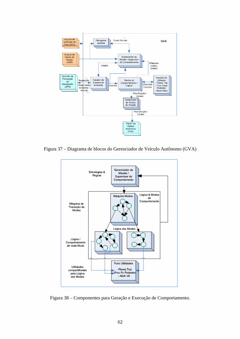
62
Figura 37 – Diagrama de blocos do Gerenciador de Veículo Autônomo (GVA)
Figura 38 – Componentes para Geração e Execução de Comportamento.
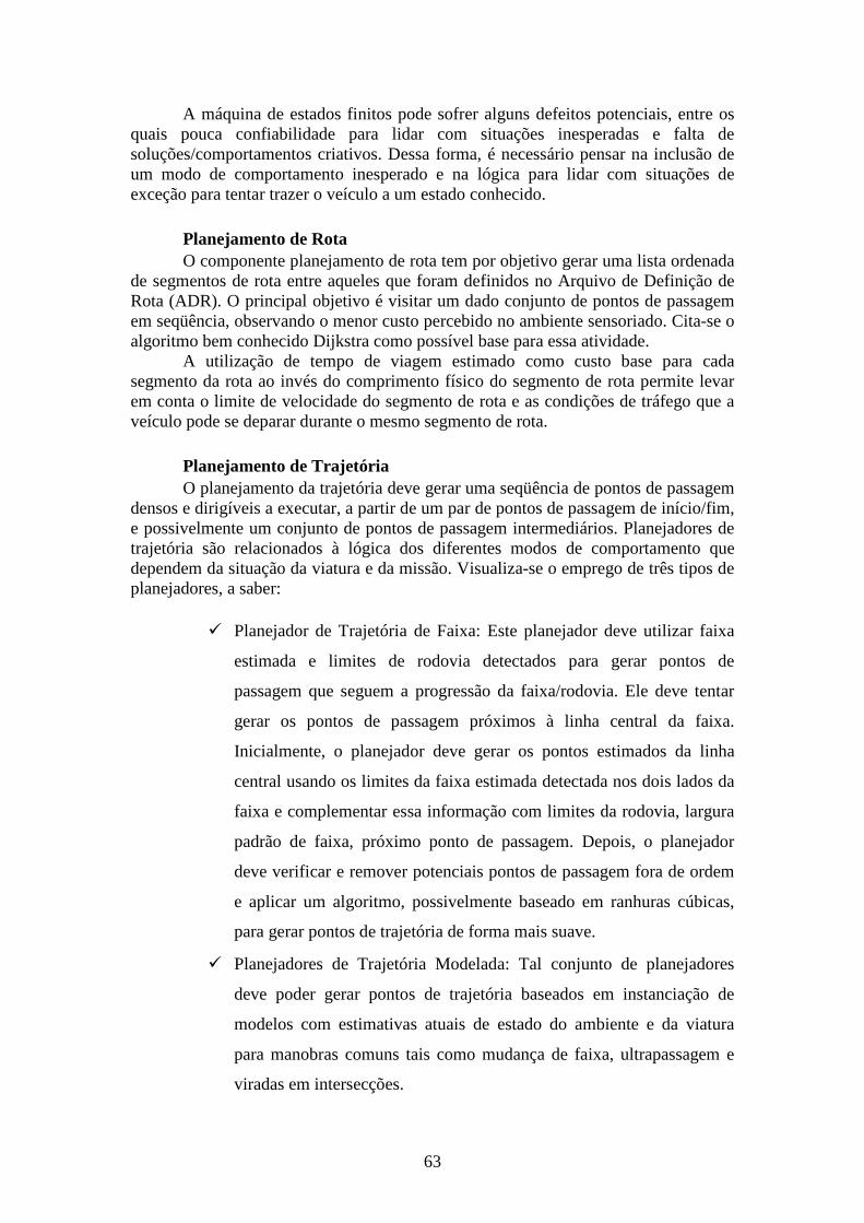
63
A máquina de estados finitos pode sofrer alguns defeitos potenciais, entre os quais pouca confiabilidade para lidar com situações inesperadas e falta de soluções/comportamentos criativos. Dessa forma, é necessário pensar na inclusão de um modo de comportamento inesperado e na lógica para lidar com situações de exceção para tentar trazer o veículo a um estado conhecido.
Planejamento de Rota O componente planejamento de rota tem por objetivo gerar uma lista ordenada
de segmentos de rota entre aqueles que foram definidos no Arquivo de Definição de Rota (ADR). O principal objetivo é visitar um dado conjunto de pontos de passagem em seqüência, observando o menor custo percebido no ambiente sensoriado. Cita-se o algoritmo bem conhecido Dijkstra como possível base para essa atividade.
A utilização de tempo de viagem estimado como custo base para cada segmento da rota ao invés do comprimento físico do segmento de rota permite levar em conta o limite de velocidade do segmento de rota e as condições de tráfego que a veículo pode se deparar durante o mesmo segmento de rota.
Planejamento de Trajetória O planejamento da trajetória deve gerar uma seqüência de pontos de passagem
densos e dirigíveis a executar, a partir de um par de pontos de passagem de início/fim, e possivelmente um conjunto de pontos de passagem intermediários. Planejadores de trajetória são relacionados à lógica dos diferentes modos de comportamento que dependem da situação da viatura e da missão. Visualiza-se o emprego de três tipos de planejadores, a saber:
� Planejador de Trajetória de Faixa: Este planejador deve utilizar faixa
estimada e limites de rodovia detectados para gerar pontos de
passagem que seguem a progressão da faixa/rodovia. Ele deve tentar
gerar os pontos de passagem próximos à linha central da faixa.
Inicialmente, o planejador deve gerar os pontos estimados da linha
central usando os limites da faixa estimada detectada nos dois lados da
faixa e complementar essa informação com limites da rodovia, largura
padrão de faixa, próximo ponto de passagem. Depois, o planejador
deve verificar e remover potenciais pontos de passagem fora de ordem
e aplicar um algoritmo, possivelmente baseado em ranhuras cúbicas,
para gerar pontos de trajetória de forma mais suave.
� Planejadores de Trajetória Modelada: Tal conjunto de planejadores
deve poder gerar pontos de trajetória baseados em instanciação de
modelos com estimativas atuais de estado do ambiente e da viatura
para manobras comuns tais como mudança de faixa, ultrapassagem e
viradas em intersecções.

64
� Planejador de Trajetória de Espaço Aberto: Este planejador deve
providenciar geração de trajetória e evitar obstáculos em uma zona pré-
determinada onde obstáculos podem estar presentes.
65
Áreas Temáticas e Linhas de Pesquisa
De acordo com o Edital do Programa criado pela Portaria do MCT Nº429, dentre as áreas temáticas priorizadas, uma é particularmente contemplada com a presente proposta, a saber:
Ciência, tecnologia e inovação em Defesa Nacional & Segurança Pública. As instituições, formando uma Rede de Pesquisa em Mobilidade Terrestre
atuarão, principalmente, nas seguintes linhas de pesquisa:
Navegação Autônoma Atividade desenvolvida pelo Laboratório de Navegação Robótica e
Realidade Virtual sediado no Departamento de Mecânica Computacional da Faculdade de Engenharia Mecânica da UNICAMP
Segundo Francisco Bonin-Font e dois co-autores, em artigo recentemente
publicado no Journal of Intelligent and Robotic Systems, o ato de navegar em robótica, diz respeito ao processo de determinar uma trajetória entre dois pontos – início e objetivo, baseando-se em sinais de diferentes sensores. Para a navegação aérea ou em terra, denominada autônoma, o sensor mais utilizado em combinação com outros tipos é o de visão, enquanto, na aplicação sob a água, a navegação baseia-se em sinais acústicos.
De modo geral, pode-se subdividir a navegação em duas grandes classes:
� Ambiente previamente conhecido;
� Não existem dados sobre o ambiente (exceto tarefa).
A segunda classe é genericamente denominada como sistemas de navegação sem mapa e tem sido objeto de grande interesse estratégico e militar.
O envolvimento de pesquisadores do Departamento de Mecânica Computacional com navegação robótica autônoma em ambiente desconhecido e desestruturado tem mais de uma década de resultados teóricos promissores (e práticos mais emergentes), com a utilização, principalmente, de redes neurais e processamento de imagens. O primeiro estudo baseou-se na morfologia do hipocampo, órgão responsável pelo sentido de orientação no ser humano em conjunto com uma teoria de aprendizado conexionista baseada na teoria de Gagnet. Os resultados teóricos e de simulação computacional foram consistentes para diferentes configurações de ambientes, conseguindo a rede neural realizar a tarefa dada na quase totalidade dos casos. Mesmo tarefas que impunham o retorno à trajetória já percorrida foram completadas, com a implementação de memórias de curto e longo prazo. A evolução dos trabalhos resultou na utilização da visão (mono) como sensor principal de identificação do ambiente. Através de uma dissertação de mestrado foi construído um primeiro protótipo, bastante simples, consistindo de um pequeno modelo com dois servomotores em malha aberta, cuja aquisição de sinais era através da câmera de um celular. Embora o experimento fosse bastante simples, a robustez e rapidez do
66
processamento de imagem trouxe resultados muito próximos aos dos realizados na pratica. O processo de aquisição baseado em Otsu, recebeu o nome de TH Finder.
A presente linha de pesquisa se caracteriza como a evolução dos trabalhos realizados até o presente momento, uma vez que se pretende atuar em dois níveis em paralelo.
No primeiro nível, teórico e de simulação, pretende-se desenvolver uma metodologia para a navegação autônoma, baseando-se em uma plataforma que emule os sinais dos diferentes sensores utilizados na prática. Dentre as diferentes plataformas livres, cite-se o Robotics Studio®, que foi utilizada pela equipe de Pittsburg por ocasião do Grand Challenge patrocinado pelo DARPA (maiores detalhes podem ser obtidos na primeira parte do presente documento). É importante ressaltar que os resultados obtidos nesta primeira fase possibilitam sua aplicação em um Sistema de Assistência ao Condutor, conforme exaustivamente detalhado no decorrer deste documento.
A segunda etapa, de implementação em um veículo fora de estrada com um nível mínimo de automatização (direção eletricamente assistida, assistência eletrônica de frenagem e de atitude dinâmica, câmbio eletromecânico tipo tiptronic), deverá ser desenvolvida em estreita cooperação com os outros grupos de pesquisa que compõe a presente proposta, uma vez que a estratégia de navegação basear-se-á na fusão de sinais de diferentes sensores, em particular, visão e laser. De acordo com diferentes autores e grupos de pesquisa atuando nesta área, os movimentos são função da aquisição (correta ou errônea) do ambiente, que se dá por dois métodos principais: fluxo ótico e navegação baseada na aparência. Como se pretende, além disso, navegar em ambientes desestruturados, duas situações podem ocorrer: a navegação aleatória, utilizada em exploração espacial e a missão com um dado objetivo, que é o resultado a que se propõe alcançar. Uma das técnicas que tem trazido bons resultados é o mapeamento realizado simultaneamente à localização. O processo clássico utilizado é a construção de mapas 3D utilizando a estéreo visão. Como se pode notar a presente linha de pesquisa servirá de processo aglutinador dos desenvolvimentos realizados nos outros laboratórios, em particular no de visão e de navegação inercial. Em síntese, a partir de desenvolvimentos prévios, baseados em redes neurais e no processamento de imagens, pretende-se construir um protótipo virtual, validando-o posteriormente, com habilidade de se locomover em ambientes desestruturados desconhecidos, na presença de obstáculos móveis. A aplicação do protótipo em terreno irregular só será feita após a validação do rendimento e da robustez dos métodos de controle e de identificação da trajetória e dependerá em primeira instância do desenvolvimento dos subsistemas de suspensões adaptativas, objeto de outra linha de pesquisa do presente projeto. Percepção e Redes de Comunicação
Atividades desenvolvidas pelos Laboratórios de Percepção de Tempo Real baseada em Sensores e Laboratório de Redes de Comunicação sediados no Departamento de Engenharia de Telecomunicações e Controle da Escola Politécnica da USP
O auxilio a humanos, por sistemas automatizados, semi-autônomos e autônomos é uma tendência decorrente da evolução tecnológica. Sua aplicação à Área de Segurança Pública e Defesa Nacional, por exemplo: auxiliando condutores de veículos em estradas e vias públicas, e nos casos de guerra ou de grande hostilidade
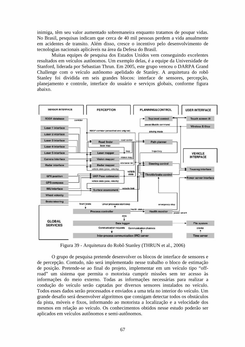
67
inimiga, têm seu valor aumentado sobremaneira enquanto tratamos de poupar vidas. No Brasil, pesquisas indicam que cerca de 40 mil pessoas perdem a vida anualmente em acidentes de transito. Além disso, cresce o incentivo pelo desenvolvimento de tecnologias nacionais aplicáveis na área da Defesa do Brasil.
Muitas equipes de pesquisa dos Estados Unidos vem conseguindo excelentes resultados em veículos autônomos. Um exemplo delas, é a equipe da Universidade de Stanford, liderada por Sebastian Thrun. Em 2005, este grupo venceu o DARPA Grand Challenge com o veículo autônomo apelidado de Stanley. A arquitetura do robô Stanley foi dividida em seis grandes blocos: interface de sensores, percepção, planejamento e controle, interface do usuário e serviços globais, conforme figura abaixo.
Figura 39 - Arquitetura do Robô Stanley (THRUN et al., 2006) O grupo de pesquisa pretende desenvolver os blocos de interface de sensores e
de percepção. Contudo, não será implementado nesse trabalho o bloco de estimação de posição. Pretende-se ao final do projeto, implementar em um veículo tipo “off-road” um sistema que permita o motorista cumprir missões sem ter acesso às informações do meio externo. Todas as informações necessárias para realizar a condução do veículo serão captadas por diversos sensores instalados no veículo. Todos esses dados serão processados e enviados a uma tela no interior do veículo. Um grande desafio será desenvolver algoritmos que consigam detectar todos os obstáculos da pista, móveis e fixos, informando ao motorista a localização e a velocidade dos mesmos em relação ao veículo. Os conhecimentos obtidos nesse estudo poderão ser aplicados em veículos autônomos e semi-autônomos.
68
Para atingir os objetivos supracitados, pretende-se criar dois laboratórios, onde serão desenvolvidas duas linhas de pesquisas, contando com apoio de professores do departamento, especialistas contratados e alunos de iniciação científica, mestrado e doutorado. Os objetivos intermediários, que balizarão o andamento da pesquisa são expostos abaixo:
a) Conhecer os principais sensores empregados em veículos autônomos; b) Conhecer os principais algoritmos utilizados para detectar obstáculos com
auxílio de multi-sensores; c) Conhecer as principais técnicas de identificação de obstáculos; d) Realizar simulações empregando sensores em robôs em testes em laboratórios,
detectando os obstáculos; e) Desenvolver uma IHM capaz de orientar o motorista para a realização de
missões de deslocamento; f) Implementar em um veículo de passeio uma IHM e sensores embarcados a fim
de cumprir tarefas de deslocamento.
Na primeira linha de pesquisa, denominada genericamente como Interface de Sensores e Percepção será necessário estudar os principais sensores utilizados em veículos autônomos e verificar quais são os melhores sensores a serem empregados, conciliando a melhor técnica e menor preço. Em vários trabalhos, empregam-se diversos tipos de sensores como laser, radar, sonar, monovisão, estéreo visão. Há a necessidade de se conhecer cada tipo desses sensores, identificando suas principais características, funcionamentos, limitações, custos, protocolo de comunicação e condições externas que podem ser submetidos. Um grande desafio será desenvolver um bloco que reconheça sinais oriundos de diversos tipos de sensores e faça a integração dos mesmos.
Aspectos importantes a serem verificados:
� Correção de não idealidades dos sensores; � Compensação de influências não desejadas na medição; � Estimação de grandezas indiretas relacionadas à grandeza de medição; � Extração de padrões e características do sinal, relativos à grandeza medida; � Remoção ou redução de ruído; � Fusão de Sensores; � Aplicação em sistemas embarcados;
A principal tarefa do bloco de percepção é integrar os sinais oriundos de diversos sensores para confirmar a existência ou não de um obstáculo e determinar com precisão informações como distância e velocidade em relação ao veículo. Aspectos importantes a serem verificados:
� Filtros de Kalman; � Filtragem Morfológica; � Processamento de Imagens; � Reconhecimento de Padrões; � Fluxo Óptico; � Mapeamento; � Algoritmos Básicos de Medição;
69
� Predição de Colisões
Quanto à segunda linha de pesquisa, envolvendo Redes de Comunicação, um detalhamento mais aprofundado foi apresentado na introdução do presente projeto e não será repetido aqui.
Navegação Inercial
Atividade desenvolvida pelo Laboratório de Navegação Inercial do Departamento de Engenharia Mecânica e de Materiais do Instituto Militar de Engenharia
Navegação inercial é definida como a determinação da posição, velocidade e orientação angular (atitude) de um veículo em relação a um sistema de coordenadas. Um SNI (Sistema de Navegação Inercial) é um sistema que usa um computador e sensores de movimento para calcular continuamente a posição, a orientação e a velocidade de um veículo sem a necessidade de referências externas como o GPS (Global Positioning System), por exemplo, tornando-o auto-suficiente (SAVAGE, 1998a). Esta vantagem torna o SNI único e bastante atraente para aplicações de navegação (SAVAGE, 1998b), (BEKIR, 2007).
Sistemas de navegação inerciais têm uma enorme gama de aplicações, e podem ser usados em diferentes tipos de veículos, como: aeronaves, mísseis, submarinos, torpedos, navios, plataformas flutuantes, carros, etc. Como todo método, a navegação inercial tem vantagens e desvantagens. Imprecisão na trajetória como resultado de erros acumulados com o tempo, é sua principal desvantagem. Erros estes que são conseqüências, principalmente, dos erros de medição inerentes aos sensores e aos erros de integração dos sinais de aceleração e velocidade. Esta desvantagem pode ser atenuada for utilizado o SNI integrado com outros sensores não inerciais, como o GPS, o baroaltímetro, o magnetômetro, etc. Se optar-se pelo GPS para integrar ao SNI, por exemplo, temos um Sistema de Navegação Inercial Integrado com o GPS (SNI/GPS). Sabendo que o GPS também tem suas componentes de erro nas informações fornecidas, faz-se necessário o uso de um método de fusão sensorial para fazer esta integração e assim fornecer com a maior exatidão possível os parâmetros desejados (LITMANOVICH et al., 2000).
Dentre os métodos de fusão de dados, o Filtro de Kalman é um dos que tem apresentado os melhores resultados. Ele determina, segundo um critério de otimização, os dados de navegação a partir das medidas dos sensores inerciais, utilizando um modelo determinístico que descreve a dinâmica dos erros de um SNI, e um modelo que descreve o comportamento estocástico dos erros das medidas dos sensores inerciais (SHIN, 2001), (BEKIR, 2007). Portanto, a qualidade das estimativas obtidas pelo Filtro de Kalman depende da exatidão das medidas fornecidas pela IMU (Unidade de Medidas Inerciais) e do desempenho dos modelos adotados. O desempenho do SNI portanto, está diretamente relacionado à qualidade dos sensores inerciais acelerômetros e giroscópios (DE SOUZA PINTO, 2007) e (ROCHA, 2006)..
Em se tratando de simulação e implementação em hardware, os avanços nesta área podem ser atribuídos não só ao poder computacional alcançado nos últimos anos, mas também às novas formulações matemáticas que acabam por ter uma grande parcela de responsabilidade na velocidade de implementação de protótipos. Um
70
exemplo é a ferramenta Real Time Workshop do software Matlab da Mathworks. Até então, o desenvolvimento de aplicações em tempo real exigia um bom conhecimento de linguagens de programação para tempo real e as vezes um profundo conhecimento de métodos numéricos. Um interessante modo de se contornar isso é oferecido pelo Matlab/Simulink/Real Time Workshop, ou simplesmente RTW. O RTW ( Real Time Workshop ) é um gerador automático de código C com diretivas de tempo real para o simulink. Com o Simulink é possível criar, simular e analisar sistemas dinâmicos complexos com simples conexões entre blocos funcionais, sendo a maioria já disponíveis em várias bibliotecas pré-configuradas dentro de uma interface gráfica amigável. A principal vantagem de seu uso reside na notação matemática familiar para expressar o problema bem como na visualização e análise de qualquer sinal do modelo. Ao se usar esta ferramenta, o usuário pode se concentrar estritamente nos problemas de modelagem e controle ao invés de gastar um tempo considerável em problemas de programação. É o RTW então, que controla a tradução do modelo feito em Simulink para uma série de funções em C que também é compilado e “linkado” para então se obter um arquivo executável.
O desenvolvimento da navegação inercial iniciou-se por volta de 1900 na Alemanha e nos Estados Unidos visando aplicações militares. Com o domínio das técnicas, sua utilização foi expandida para o meio civil. Das inúmeras aplicações dos sistemas inerciais podem-se destacar:
• Navegação, guiagem e controle de navios, submarinos e aeronaves; • Guiagem de torpedos e mísseis de curto, médio e longo alcance; • Geodésia e cartografia; • Robótica, VANT ( Veículo Aéreo não Tripulado ), VSA ( Veículo Submarino
Autônomo ) e VTA ( Veículo Terrestre Autônomo ); • Estabilização de plataformas (de tiro, de petróleo, de equipamentos de
filmagens); • Missões espaciais (lançamento de satélites); • Estabilização de satélites; • Acompanhamento de trajetória de perfuração petrolífera; • Guiagem, navegação e controle de veículos quando empregados em regiões
inóspitas ou em situações táticas; • Sistema de georreferenciamento de dutos e PIG ( Pipeline Inspection Gauge ); • Veículos terrestres autônomos; • Indústria de entretenimentos; • Mapeamento Topográfico; • Detecção de falhas estruturais por meio de análise de vibrações.
O objetivo desta linha de pesquisa é a simulação e implementação de um sistema
de navegação inercial, com algoritmo em tempo real, integrado ao GPS de modo à auxiliar na navegação de um VTA (Veículo Terrestre Autônomo).
Com o início das atividades docentes do PGED a partir de fevereiro de 2007, o Instituto busca orientar efetivamente seus cursos e pesquisas para a área de Defesa e para as necessidades do Exército Brasileiro (EB). Este objetivo encontra-se em consonância com as diretrizes do Departamento de Ciência e Tecnologia (DCT) do
71
EB e com a Política de Defesa Nacional, lançada em junho de 2005 pelo Ministério da Defesa, no que se refere à capacitação científica e tecnológica das Forças Armadas.
O PGED visa atender a demanda nacional por pessoal altamente qualificado e especializado, inves-tindo numa formação assentada em pesquisa básica de qualidade e com inserção internacional. Os cursos do PGED têm por principal finalidade a habilitação de profissionais com nível superior ao desempenho de atividades de pesquisa e docência, capacitando alunos militares e civis a ampliar e aprofundar seus conhecimentos nas diversas áreas da engenharia e das ciências voltadas aos problemas de interesse da Defesa Nacional.
As Linhas de Pequisa (LP) do PGED procuram consolidar as diversas pesquisas em Defesa dispersas pelo Instituto, bem como fomentar o desenvolvimento de áreas críticas para o EB, como no caso da LP Mecatrônica e Sistemas de Armas que está formando uma sólida base de pesquisa na área de Navegação e Sistemas Inerciais.
Através do projeto Sistema de Georreferenciamento de Dutos, CT-DUT/FINEP (2007-2008), foi criado um grupo de pesquisa em sistemas inerciais no IME, envolvendo basicamente capacitação de pessoal. Desde então já apresentadas duas dissertações de mestrado na área, havendo mais duas em andamento. Paralelamente, o IME Fo organizador do Simpósio Brasileiro de Engenharia Inercial 2007, tendo seus integrantes apresentados diversos trabalhos no mesmo. Além disso, o IME foi instituição participante na fundação da Sociedade Brasileira de Engenharia Inercial, sendo representado por dois integrantes da equipe de projeto proposta.
Através deste projeto pretende-se consolidar o grupo de pesquisa em sistemas inerciais, além de promover a formação de mestres nesta área por meio dos programas de pós-graduação em Engenharia Mecânica, Elétrica e de Defesa. Paralelamente, pretende-se instalar o Laboratório de Sensores Inerciais e Navegação, de modo a prover estrutura física para o fortalecimento da área.
Para atingir tal objetivo, muitas opções devem ser analisadas, como por exemplo, o uso de um algoritmo discretizado por ser mais adequado para a implementação em hardware e também para a programação em tempo real. A grande vantagem de se utilizar algoritmos discretos é a possibilidade de se usar um tempo de amostragem não tão pequeno, possibilitando o uso de processadores modestos e mais baratos e ainda sim obter resultados bastante próximos da realidade, embora nos dia de hoje a velocidade de processamento não seja um problema tão intenso quanto nas décadas de 60 a 90. Como plataforma de simulação e implementação em tempo real do algoritmo de navegação, pode-se utilizar o pacote computacional foi o MATLAB®/Simulink com as toolboxs Real Time Workshop e xPC Target. O Real Time Workshop gera e otimiza códigos portáveis e customizáveis ANSI C ou C++ de modelos do Simulink para criar implementações específicas de modelos que operam em tempo real. O código gerado pode rodar em Pcs, microcontroladores e DSPs e ainda rodar em qualquer sistema operacional de tempo real (RTOS).
O xPC Target é um ambiente para a prototipagem, teste e desenvolvimento de sistemas que funcionem em tempo real para computadores padrões. Ele utiliza um computador target, separado do computador host, para rodar aplicações em tempo real. Um computador target pode ser praticamente qualquer computador com um Intel 386 ou 486 ou AMD K5 ou K6/Athlon, pode ser um computador de mesa ou um computador industrial como um PC104 que será usado neste trabalho. A partir de uma simulação criada normalmente no Simulink, pode-se gerar um código executável a partir do RTW, tendo como alvo o próprio xPC Target. O código executável e o xPC Target real-time Kernel é então gravado do computador host para o target. Em
72
seguida, pode-se rodar a aplicação em tempo real, com a possibilidade de variação "online" dos parâmetros do modelo.
Assim, algumas etapas podem ser estabelecidas para o desenvolvimento do trabalho:
1. Estudo do problema de navegação em VTAs, definição de arquitetura de navegação e instrumentação
2. Estudo sobe acelerômetros e girômetros, analisando princípios e tecnologias apropriadas à aplicação de navegação para um VTA
3. Desenvolvimento de um gerador de entradas, isto é, um modelo que simule o comportamento das variáveis da VTA de interesse para a navegação
4. Desenvolvimento do modelo de instrumentação 5. Desenvolvimento do algoritmo de navegação integrado 6. Estudo de normas sobre ensaios e procedimentos práticos (no Brasil): Ensaios
principais normalmente executados e normas seguidas, fabricantes, etc... 7. Ensaios com vistas à seleção do sensor e aplicação em VTA. 8. Implementação da unidade SNI integrada com GPS 9. Testes da unidade SNI integrada com GPS isolada 10. Testes da unidade SNI/GPS integrada à VTA.
Visão por Computador
Atividade desenvolvida pelo Laboratório de Visão por Computador do Departamento de Automação e Controle da Faculdade de Engenharia Elétrica e de Computação da Unicamp
Em geral, para sistemas de navegação autônoma e semi-autônoma, o sistema
de visão é aplicado à percepção do ambiente em torno do veículo. Desta forma, inicialmente, o sistema de visão deverá ser capaz de fornecer sensoriamento para implementar as seguintes funcionalidades:
� Detecção da área de navegação;
� Detecção de linhas e sinalização de trânsito;
� Detecção de tráfego;
O que é trivial para o sistema humano, construir cenas tridimensionais a partir
de imagens bidimensionais captadas pelo sistema de visão, e a partir destas tomar decisões precisas para a navegação, pode não ser trivial para os sistemas computacionais.
Diferentemente do sistema humano, sistemas de processamento e análise de visão computacional mais complexos podem desencadear alguns prejuízos devido ao tempo de processamento. Como exemplo, temos a alta demanda de informações que são submetidas ao sistema de visão, em função da relação existente entre um sistema de decisão em tempo real, com um sistema de leitura de imagens que opera em uma determinada taxa de captação/leitura, isto é, quantidade de imagens geradas por segundo.
73
Neste sentido, a decisão por um sistema de visão computacional mais complexo pode levar a um sistema lento demais para uma aplicação autônoma de tempo real. Ou ainda a escolha automática por um processo randômico de descarte de informações pelo sistema, para torná-lo suficientemente rápido, pode resultar em perda de informações importantes.
As aplicações mais comuns baseiam-se no processamento de duas ou mais imagens, a partir da análise do campo de fluxo óptico ou através de imagens não monoculares. Basicamente, num primeiro caso, temos sistemas de navegação em que mais de uma imagem é adquirida por uma câmera em momentos diferentes, enquanto que em um segundo caso, múltiplas câmeras são usadas para adquirem imagens simultaneamente, porém, de pontos de “vistas” diferentes.
Ferramenta importante para atividades de navegação baseada em visão computacional tem especial atenção o processo de segmentação, que consiste em subdividir uma imagem em suas partes ou em objetos constituintes. Esse processo de segmentação deve seguir até que os objetos de interesse da imagem tenham sido isolados. Tal tarefa pode ser extremamente sofisticada, e a partir de filtros bem elaborados, pode-se chegar a resultados muito eficientes. Porém, estes resultados podem exigir um alto preço, isto é, normalmente algoritmos de segmentação robustos apresentam grande complexidade. Basicamente, a segmentação pode ser considerada como partição de imagens digitais em conjuntos de pixels, considerando-se a necessidade geral e critérios previamente definidos.
Para detecção da área de navegação, diversos algoritmos podem ser utilizados. Dentre estes, pretende-se dar ênfase ao método desenvolvido e testado pelo Laboratório de Sistemas Ativos e Mecatrônica do Departamento de Mecânica Computacional da Faculdade de Engenharia Mecânica da Unicamp, denominado TH Finder (Threshold and Horizon Finder), que por sua vez é baseado no método de segmentação de Otsu.
Em laboratório deverão ser repetidas e simuladas as diferentes condições de iluminação encontradas na natureza, tanto aquelas favoráveis que reproduzem um dia ensolarado com sol a pino, como situações difusas tais como amanhecer e/o entardecer. Esta linha de pesquisa tem o propósito de desenvolver algoritmos mais robustos, que conjuntamente com sinais de outros sensores levem a uma confiabilidade maior.
Suspensões Hidro-Pneumáticas Inteligentes
Atividade desenvolvida pelo Laboratório de Sub-Sistemas para Veículos Inteligentes do Departamento de Mecânica Computacional da Faculdade de Engenharia Mecânica da Unicamp
Dentre as diversas tecnologias utilizadas para realizar os sistemas de
suspensão automotivas, as suspensões pneumáticas e hidropneumáticas tem atraído a atenção dos engenheiros já faz bastante tempo. Elas apresentam excelentes propriedades com relação à filtragem das perturbações externas, proporcionando conforto e segurança. De uma comparação entre os dois sistemas mencionados resulta que os sistemas pneumáticos tem a vantagem de utilizar fluido barato, abundante e não
74
poluente (ar), entanto que os sistemas hidropneumáticos, além de ter ligeira desvantagem no custo inicial, requerem mais cuidados por utilizarem óleo no circuito. Por outro lado, os sistemas hidropneumáticos apresentam maior controlabilidade por ter respostas rápidas, dispensam o uso de amortecedores adicionais e são mais robustos e tolerantes a grandes variações nas condições de operação. O maior custo, quando comparados com as suspensões mecânicas de molas helicoidais, feixes elípticos e barras de torção, fazem com que estes sistemas de suspensão sejam muito menos utilizados do que as suspensões mecânicas nas aplicações mais comuns, apesar do excelente desempenho apresentado, sendo mais fácil encontrar aplicações em veículos pesados, veículos ferroviários, trens de pouso de aeronaves, veículos fora de estrada, máquinas agrícolas e veículos militares. Nos automóveis destinados ao grande público e exceção o caso da marca Citroën, que vêm utilizando suspensões hidropneumáticas nos seus veículos, de forma ininterrupta e com grande sucesso, desde 1955 ate o presente. Esta situação têm apresentado sintomas de mudança nos últimos anos, com a disponibilização de veiculo com suspensão pneumática ou hidropneumática nas marcas Mercedes Benz, Jeep Cherokee e outros. Esta mudança pode ser atribuída à crescente exigência do consumidor, mas também às mudanças de paradigmas tecnológicos: As suspensões convencionais não possibilitam tirar proveito dos recursos de monitoração e controle disponibilizados pela evolução da mecatrônica. Além disso, atualmente a maior parte dos veículos já tem serviço hidráulico, por exemplo, o da direção assistida, eliminando um dos "tabus" que pesavam sobre a implementação das suspensões hidropneumáticas.
No Brasil tem havido poucas ou nenhuma iniciativa da indústria no desenvolvimento de suspensões hidropneumáticas. Suspensões pneumáticas são utilizadas em alguns modelos de caminhões e principalmente na maior parte dos ônibus interurbanos, devido ao conforto que proporcionam. É necessário que essas tecnologias sejam desenvolvidas, sob pena de alguns setores ligados à mobilidade ficarem novamente dependentes de tecnologia importada num futuro bem próximo. Na Universidade tem sido desenvolvidas pesquisas para compreender os princípios básicos e principais características das suspensões hidropneumáticas. Em particular, no Departamento de Mecânica Computacional da FEM/UNICAMP vêm sendo desenvolvidas pesquisas sobre este assunto desde 1996. Estes estudos resultaram em diversas publicações. Algumas delas são citadas nas referencias [22] a [33]. A referência [28] recebeu o premio de melhor trabalho de NVH do evento no qual foi apresentada. A análise das referências citadas mostra que existem diferentes assuntos relacionados com o estudo e aplicação de suspensões hidropneumáticas: dinâmica, vibração e controle são alguns destes tópicos já abordados.
Considerando o aspecto interdisciplinar deste assunto e a evolução atingida pelas pesquisas realizadas, e chegado o momento de se criar uma infraestrutura capaz de nuclear os trabalhos das diferentes áreas, possibilitando levar mais longe os resultados obtidos. Esta evolução implica em montar uma infraestrutura melhor aparelhada para a realização de experiências realistas e testes de campo. Estes experimentos fazem parte do processo para conseguir disponibilizar um produto de alto desempenho e valor tecnológico, aliado a alta confiabilidade. Várias linhas de pesquisa devem ser aprofundadas. A seguir serão listadas algumas delas.
75
1 - Controle de altura. Uma das vantagens freqüentemente mencionada das suspensões hidropneumáticas e a de possibilitar a mudança de altura do veículo sem nenhuma intervenção mecânica, proferindo grande adaptabilidade às condições de uso. Mas para isso se faz necessário contar com sensores, atuadores e estratégia de controle adequados. A abordagem utilizada pode variar significativamente em função da aplicação pretendida. O controle pode ser realizado de forma totalmente mecânica, tal como acontece atualmente com os ônibus interurbanos e trens urbanos dotados de suspensão pneumática, ou pode ser realizada utilizando processamento computacional e estratégias de controle sofisticadas, aliados a sensores e atuadores. Diversas abordagens se encontram hoje prontas, em consequência de resultados de pesquisas anteriores, para serem testadas em condições reais de operação, com o objetivo de validação e avaliação comparativa.
2 - Controle de amortecimento Uma característica evidenciada pelos estudos de suspensões hidropneumáticas efetuados, e a sua alta sensibilidade do fator de amortecimento a variações de carga. A solução deste problema requer alguma forma de controle. Novamente existe a opção de soluções clássicas e relativamente sofisticadas, baseadas no uso de processamento digital de sinais aliado ao uso de sensores e atuadores, ou a aplicação de opções inovadoras mais robustas, ficando a escolha condicionada as características da aplicação pretendida.
3 - Ajuste preciso da curva característica A curva de rigidez das suspensões hidropneumáticas é função dos parâmetros geométricos, e podem ser deduzidas utilizando as propriedades do gás. Estas curvas devem ser ajustadas experimentalmente para levar em consideração aspectos difíceis de serem modelados, tais como atrito entre as peças. Além disso, e possível alterar a curva convenientemente mediante o projeto adequado dos componentes e o uso de outros recursos, por exemplo multi-câmeras [34]. Alguns aspectos práticos, tais como diferentes opções de válvulas passivas para controlar a participação de cada câmara, devem ser verificados experimentalmente.
4 - Critérios de dimensionamento Existem hoje informações e experiência suficientes para orientar o projeto de suspensões hidropneumáticas para uma dada aplicação. É interessante colocar esta experiência em um procedimento sistemático, criando ferramentas que auxiliem nesta tarefa.
5 - Acionamento
O alto custo de implementação das suspensões hidropneumáticas está relacionado com o custo dos componentes hidráulicos. Existe a possibilidade de uso de componentes especialmente desenhados para esta aplicação, proporcionando economia sem prejudicar, e em alguns casos até, com aprimoramento do rendimento e robustez.
6 - Simulador de vias Para realizar os testes em laboratório e imprescindível o uso de um Simulador de Vias. Simulador de Vias é o nome genérico pelo qual e conhecido, no meio automobilístico, um sistema de testes de laboratório capaz de reproduzir as condições
76
de uso registradas em campo. Com pequenas variações, sistemas com essas características são oferecidos pelas empresas líderes em sistemas de testes. Basicamente um sistema de simulação de vias consiste na implementação experimental da solução de um problema de identificação inversa de sistema não linear. O fato do sistema (veículo) ser não linear implica na necessidade de se utilizar processos de ajustes iterativos no domínio do tempo ou da freqüência, aliando conceitos avançados de análise de sinais com a técnica "Hardware In the Loop". Sistemas como esse são usados na indústria automobilística para a realização de testes de durabilidade em laboratório mas com condições de severidade realistas, e também para simulações de comportamento de veículos utilizando Realidade Virtual.
7 - Testes em laboratório Testes em laboratório serão necessários para a condução dos trabalhos, durante praticamente todo o desenvolvimento do projeto.
8 - Testes em campo Apesar dos testes em laboratório reduzirem significativamente a necessidade de realizar testes em campo, estes se fazem necessarios para a completa validação das soluções desenvolvidas. Por essa razão devem ser realizados testes em campo no final de cada grande etapa da pesquisa.
Para a execução das pesquisas citadas se faz necessário contar com uma infraestrutura adequada. A UNICAMP conta com parte dos recursos necessários, mas eles devem ser complementados, em particular no que diz respeito à bancada para testes em escala real. Estes testes devem incluir a possibilidade de testes de veículos completos, utilizando a técnica conhecida no meio automobilístico como "simulação de vias". Esta técnica exige recursos de "hardware" e "software" adequados. O "hardware" consiste basicamente de sistemas servo-hidráulicos de testes dinâmicos com características adequadas. A Unicamp conta com sistemas deste tipo, mas se fazem necessárias algumas adaptações. Com relação ao "software", os mais conhecidos são o RPC da MTS e o RTW da IST. A presente linha de pesquisa se insere no contexto do Instituto de Mobilidade Terrestre por dois aspectos principais:
� Permite a criação, em realidade virtual, de terrenos irregulares com diferentes pavimentações a partir de programas computacionais baseados na aquisição de sinais de campo e posterior processamento. Esta ferramenta será importante para a validação dos protótipos veiculares em ensaios em laboratório;
� Resultará na concepção de produtos de alto valor tecnológico agregado, tais como novas servo-válvulas com aplicação em suspensões automotivas de modo geral e, em especial, para veículos militares, agrícolas e fora de estrada.
Material de Emprego Militar
Atividade desenvolvida pelo Laboratório de Controle Remoto de Sistemas Militares do Centro Tecnológico do Exército.
O CTEx é o órgão do Exercito Brasileiro responsável pela Pesquisa Aplicada e
Desenvolvimento Experimental de Material de Emprego Militar (MEM). Como tal,
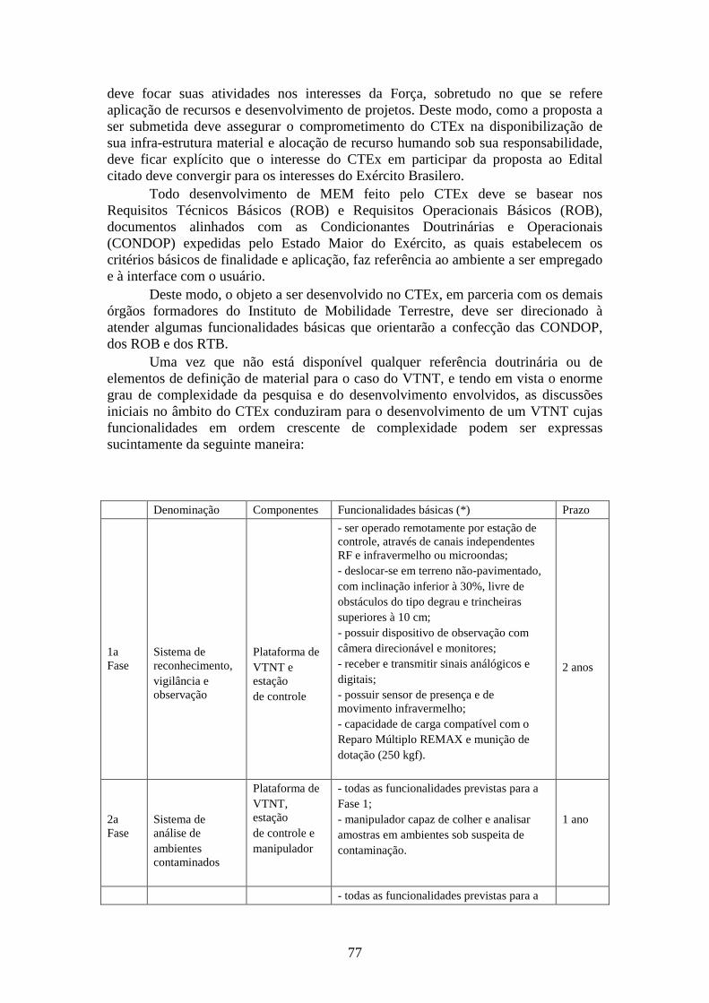
77
deve focar suas atividades nos interesses da Força, sobretudo no que se refere aplicação de recursos e desenvolvimento de projetos. Deste modo, como a proposta a ser submetida deve assegurar o comprometimento do CTEx na disponibilização de sua infra-estrutura material e alocação de recurso humando sob sua responsabilidade, deve ficar explícito que o interesse do CTEx em participar da proposta ao Edital citado deve convergir para os interesses do Exército Brasilero.
Todo desenvolvimento de MEM feito pelo CTEx deve se basear nos Requisitos Técnicos Básicos (ROB) e Requisitos Operacionais Básicos (ROB), documentos alinhados com as Condicionantes Doutrinárias e Operacionais (CONDOP) expedidas pelo Estado Maior do Exército, as quais estabelecem os critérios básicos de finalidade e aplicação, faz referência ao ambiente a ser empregado e à interface com o usuário.
Deste modo, o objeto a ser desenvolvido no CTEx, em parceria com os demais órgãos formadores do Instituto de Mobilidade Terrestre, deve ser direcionado à atender algumas funcionalidades básicas que orientarão a confecção das CONDOP, dos ROB e dos RTB.
Uma vez que não está disponível qualquer referência doutrinária ou de elementos de definição de material para o caso do VTNT, e tendo em vista o enorme grau de complexidade da pesquisa e do desenvolvimento envolvidos, as discussões iniciais no âmbito do CTEx conduziram para o desenvolvimento de um VTNT cujas funcionalidades em ordem crescente de complexidade podem ser expressas sucintamente da seguinte maneira:
Denominação Componentes Funcionalidades básicas (*) Prazo
1a Fase
Sistema de reconhecimento, vigilância e observação
Plataforma de VTNT e estação de controle
- ser operado remotamente por estação de controle, através de canais independentes RF e infravermelho ou microondas; - deslocar-se em terreno não-pavimentado, com inclinação inferior à 30%, livre de obstáculos do tipo degrau e trincheiras superiores à 10 cm; - possuir dispositivo de observação com câmera direcionável e monitores; - receber e transmitir sinais análógicos e digitais; - possuir sensor de presença e de movimento infravermelho; - capacidade de carga compatível com o Reparo Múltiplo REMAX e munição de dotação (250 kgf).
2 anos
2a Fase
Sistema de análise de ambientes contaminados
Plataforma de VTNT, estação de controle e manipulador
- todas as funcionalidades previstas para a Fase 1; - manipulador capaz de colher e analisar amostras em ambientes sob suspeita de contaminação.
1 ano
- todas as funcionalidades previstas para a
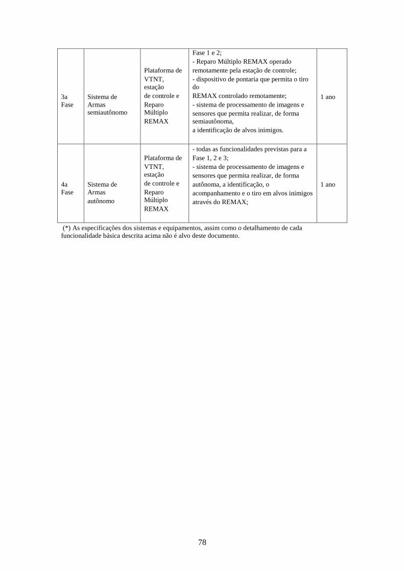
78
3a Fase
Sistema de Armas semiautônomo
Plataforma de VTNT, estação de controle e Reparo Múltiplo REMAX
Fase 1 e 2; - Reparo Múltiplo REMAX operado remotamente pela estação de controle; - dispositivo de pontaria que permita o tiro do REMAX controlado remotamente; - sistema de processamento de imagens e sensores que permita realizar, de forma semiautônoma, a identificação de alvos inimigos.
1 ano
4a Fase
Sistema de Armas autônomo
Plataforma de VTNT, estação de controle e Reparo Múltiplo REMAX
- todas as funcionalidades previstas para a Fase 1, 2 e 3; - sistema de processamento de imagens e sensores que permita realizar, de forma autônoma, a identificação, o acompanhamento e o tiro em alvos inimigos através do REMAX;
1 ano
(*) As especificações dos sistemas e equipamentos, assim como o detalhamento de cada funcionalidade básica descrita acima não é alvo deste documento.
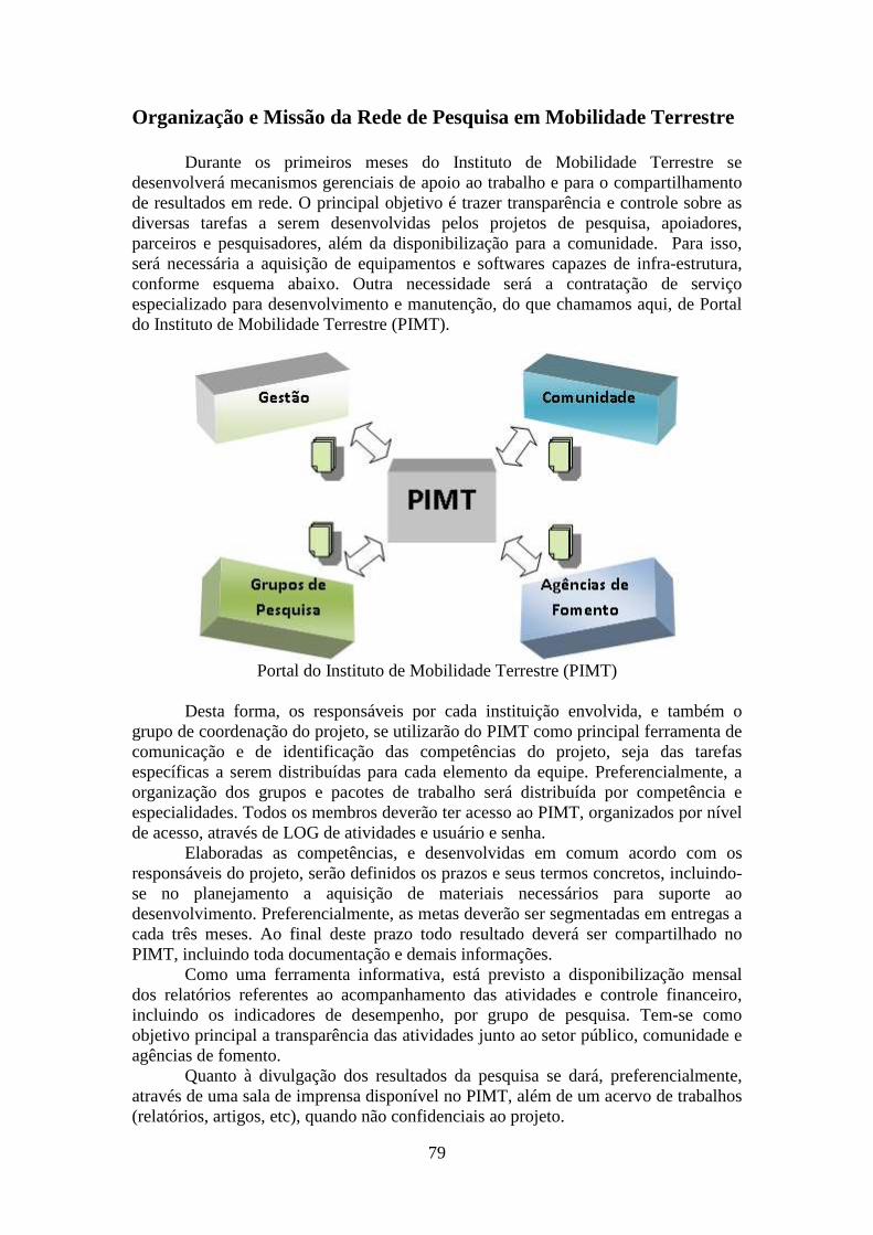
79
Organização e Missão da Rede de Pesquisa em Mobilidade Terrestre
Durante os primeiros meses do Instituto de Mobilidade Terrestre se desenvolverá mecanismos gerenciais de apoio ao trabalho e para o compartilhamento de resultados em rede. O principal objetivo é trazer transparência e controle sobre as diversas tarefas a serem desenvolvidas pelos projetos de pesquisa, apoiadores, parceiros e pesquisadores, além da disponibilização para a comunidade. Para isso, será necessária a aquisição de equipamentos e softwares capazes de infra-estrutura, conforme esquema abaixo. Outra necessidade será a contratação de serviço especializado para desenvolvimento e manutenção, do que chamamos aqui, de Portal do Instituto de Mobilidade Terrestre (PIMT).
Portal do Instituto de Mobilidade Terrestre (PIMT)
Desta forma, os responsáveis por cada instituição envolvida, e também o grupo de coordenação do projeto, se utilizarão do PIMT como principal ferramenta de comunicação e de identificação das competências do projeto, seja das tarefas específicas a serem distribuídas para cada elemento da equipe. Preferencialmente, a organização dos grupos e pacotes de trabalho será distribuída por competência e especialidades. Todos os membros deverão ter acesso ao PIMT, organizados por nível de acesso, através de LOG de atividades e usuário e senha.
Elaboradas as competências, e desenvolvidas em comum acordo com os responsáveis do projeto, serão definidos os prazos e seus termos concretos, incluindo-se no planejamento a aquisição de materiais necessários para suporte ao desenvolvimento. Preferencialmente, as metas deverão ser segmentadas em entregas a cada três meses. Ao final deste prazo todo resultado deverá ser compartilhado no PIMT, incluindo toda documentação e demais informações.
Como uma ferramenta informativa, está previsto a disponibilização mensal dos relatórios referentes ao acompanhamento das atividades e controle financeiro, incluindo os indicadores de desempenho, por grupo de pesquisa. Tem-se como objetivo principal a transparência das atividades junto ao setor público, comunidade e agências de fomento.
Quanto à divulgação dos resultados da pesquisa se dará, preferencialmente, através de uma sala de imprensa disponível no PIMT, além de um acervo de trabalhos (relatórios, artigos, etc), quando não confidenciais ao projeto.
80
Neste sentido, entende-se por mecanismos de transferência, a formação pessoas nas diversas tecnologias e avanços tecnológicos criados e sistematizados pelo Instituto de Mobilidade Terrestre, obedecendo ao caráter da informação disponibilizada. Algumas das seguintes opções poderão ser utilizadas como ferramenta de compartilhamento e/ou transferência de conhecimento, seja através de consultoria autorizada através dos membros do Instituto, compartilhamento de resultados e experimentos realizados nas salas de aula e laboratórios das Universidades e Centros de Pesquisa envolvidos; Na organização de Congressos ou Conferências; Cursos e workshops; Desenvolvimento de projetos conjuntos; Criação de empresas de alta tecnologia em torno do Instituto de Mobilidade Terrestre; Programas de estágios monitorados; Desenvolvimento de relatórios técnicos, trabalhos de conclusão de curso, dissertações de mestrado e teses de doutorado; Disponibilização de informações no PIMT, etc.
É importante salientar que a Rede de Pesquisa em Mobilidade Terrestre terá a sua disposição outros mecanismos institucionais, principalmente da Unicamp e USP, que serão utilizados nos casos em que ações centralizadas se fizerem necessárias. A difusão de conhecimento e a elaboração dos programas de educação continuada – baseada em plataformas livres como, por exemplo Moodle e Teleduc - será efetivada, administrativamente, através da Escola de Extensão da Unicamp e da FDTE-USP, enquanto a prospecção de competências e os acordos de transferência de tecnologia serão intermediados preferencialmente pelo Escritório do EB-CTEx e pela Agência Inova da Unicamp, com larga experiência em negociações envolvendo a questão de patentes e propriedade intelectual. A médio e longo prazo deverão ser estabelecidas parcerias com as incubadoras sediadas em Campinas, São Paulo e Rio de Janeiro e que tenha estreita interação com Instituições de Ensino Superior no intuito de repassar tecnologia, bem como qualificar fornecedores. Esta política de uma Rede de Pesquisa funcionar como uma espécie de “cluster” incentivando o “spin off” de empresas de média e alta tecnologia é um mecanismo bastante eficiente e pode ser considerado como um dos principais fatores que explicam o sucesso da evolução técnica de alguns países. Certamente, a inserção de pós graduandos e graduandos será um dos mecanismos mais utilizados no decorrer do projeto, mas as iniciativas deverão transcender os mecanismos normalmente utilizados para a captação de recursos humanos, utilizando, por exemplo, as Empresas Juniores das diferentes instituições envolvidas.
O Instituto de Mobilidade Terrestre visa ser um centro nacional de Ciência e Tecnologia, aberto a cientistas de outras instituições brasileiras e do exterior. Através das instituições envolvidas, seus dirigentes e pesquisadores encontram a infra-estrutura necessária para realizar tais pesquisas. Dentre suas missões, quer atuar como instituição aberta, multidisciplinar, promovendo e realizando pesquisa, desenvolvimento e transferência de tecnologias que contribuam para elevar o nível tecnológico e científico do Brasil.
Por estrutura organizacional propõe-se o seguinte esquema:
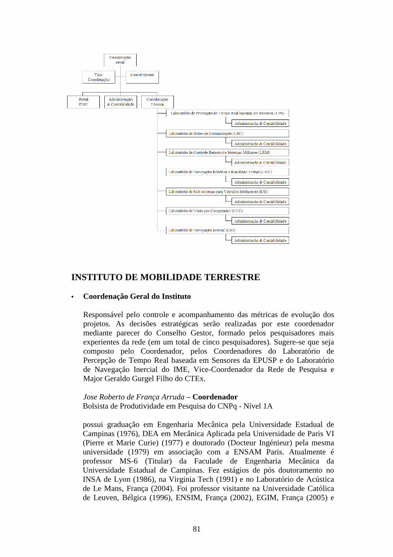
81
INSTITUTO DE MOBILIDADE TERRESTRE
• Coordenação Geral do Instituto
Responsável pelo controle e acompanhamento das métricas de evolução dos projetos. As decisões estratégicas serão realizadas por este coordenador mediante parecer do Conselho Gestor, formado pelos pesquisadores mais experientes da rede (em um total de cinco pesquisadores). Sugere-se que seja composto pelo Coordenador, pelos Coordenadores do Laboratório de Percepção de Tempo Real baseada em Sensores da EPUSP e do Laboratório de Navegação Inercial do IME, Vice-Coordenador da Rede de Pesquisa e Major Geraldo Gurgel Filho do CTEx.
Jose Roberto de França Arruda – Coordenador Bolsista de Produtividade em Pesquisa do CNPq - Nível 1A
possui graduação em Engenharia Mecânica pela Universidade Estadual de Campinas (1976), DEA em Mecânica Aplicada pela Universidade de Paris VI (Pierre et Marie Curie) (1977) e doutorado (Docteur Ingénieur) pela mesma universidade (1979) em associação com a ENSAM Paris. Atualmente é professor MS-6 (Titular) da Faculade de Engenharia Mecânica da Universidade Estadual de Campinas. Fez estágios de pós doutoramento no INSA de Lyon (1986), na Virginia Tech (1991) e no Laboratório de Acústica de Le Mans, França (2004). Foi professor visitante na Universidade Católica de Leuven, Bélgica (1996), ENSIM, França (2002), EGIM, França (2005) e
82
ECL, França (2007). É membro de comitês científicos de diversos congressos internacionais. Tem experiência na área de Mecânica dos Sólidos, com ênfase em Dinâmica, atuando principalmente nos seguintes temas: acústica e vibrações, análise de sinais e controle ativo de ruído e vibração.
Carlos Eduardo Cugnasca – Vice-Coordenador Bolsista de Produtividade em Pesquisa do CNPq - Nível 2
possui graduação em Engenharia Elétrica pela Universidade de São Paulo (1980) , mestrado em Engenharia Elétrica pela Universidade de São Paulo (1987) e doutorado em Engenharia Elétrica pela Universidade de São Paulo (1992) . Atualmente é Professor Associado da Universidade de São Paulo, Assessor do Fundação de Amparo à Pesquisa do Estado de São Paulo, Membro do Conselho Fiscal do Associação Brasileira de Agroinformática, Membro comissão normatização do Associação Brasileira de Normas Técnicas, Membro de Comissão de Normatização da International Organization For Standartization, Membro de corpo editorial da Revista Brasileira de Agroinformática, Consultor Ad Hoc do Centro Incubador de Empresas Tecnológicas, Revisor de periódico da Revista IEEE América Latina, Revisor de periódico da Computers and Electronics in Agriculture, Assessor Ad hoc do Conselho Nacional de Desenvolvimento Científico e Tecnológico, Participante da Força-Tarefa ISOBUS Brasil, Assessor Ad hoc da Empresa Brasileira de Pesquisa Agropecuária, Avaliador do Ministério da Educação e Revisor de periódico da Controle & Automação (1807-0345). Tem experiência na área de Engenharia Elétrica, com ênfase em Eletrônica Industrial, Sistemas e Controles Eletrônicos. Atuando principalmente nos seguintes temas: Eletrônica Embarcada, Agricultura de Precisão, Redes Ad Hoc.
• Conselho Gestor
Composto pelo Coordenador Geral do Projeto, Prof. Dr. José Roberto de França Arruda, pelos Coordenadores do Laboratório de Percepção de Tempo Real baseada em Sensores da EPUSP e do Laboratório de Navegação Inercial do IME, Prof. Dr. Claudio Garcia e Prof. Dr. Jorge Audrin Morgado de Góis, respectivamente, Vice-Coordenador da Rede de Pesquisa, Prof. Dr. Carlos Eduardo Cugnasca e Major Geraldo Gurgel Filho do CTEx.
• Portal do IPMT
Responsável pelo relacionamento com os usuários, com o sistema produtivo e industrial em particular, e com a sociedade de modo geral. Será implementado de forma gradativa a partir do primeiro semestre de existência do Instituto. Deverá ser contratado com recursos advindos do projeto através de processo seletivo específico.
• Coordenador Administrativo-Financeiro
Responsável não docente com larga experiência em negociação com fornecedores e legislação pública. Responsável pela gestão dos recursos
83
financeiros e estrutura administrativa do Instituto. Deverá ser contratado com recursos advindos do projeto através de processo seletivo específico.
• Coordenação Técnica
Responsável pela evolução técnica do projeto atuando em comum acordo com os Coordenadores dos diferentes Laboratórios. Deve ser um pesquisador de larga experiência, bolsista do projeto, indicado pela Coordenação e referendado pelo Conselho Gestor.
• Coordenador de Laboratório
Pesquisador responsável por uma ou mais linhas de pesquisas do projeto em questão, detalhadas no escopo do projeto apresentado. Deverá estabelecer os cronogramas de execução proposto e real, utilizando ferramentas modernas de gestão e acompanhamento dos projetos, como por exemplo, a plataforma de software livre DotProject.
Claudio Garcia – Laboratório de Percepção de Tempo Real baseada em Sensores Bolsista de Produtividade em Pesquisa do CNPq - Nível 2
possui graduação em Engenharia Elétrica Escola Politécnica pela Universidade de São Paulo (1979) , mestrado em Engenharia Elétrica pela Universidade de São Paulo (1987) e doutorado em Engenharia Elétrica pela Universidade de São Paulo (1992) . Atualmente é Professor doutor da Universidade de São Paulo. Tem experiência na área de Engenharia Elétrica , com ênfase em Eletrônica Industrial, Sistemas e Controles Eletrônicos. Atuando principalmente nos seguintes temas: otimização discreta, sistemas NP-completos, multiprocessamento, modelamento de redes de processadores, escalação heurística de tarefas.
Clésio Luis Tozzi – Laboratório de Visão por Computador
possui graduação em Engenharia Elétrica pela Universidade Estadual de Campinas (1972) , mestrado em Engenharia Elétrica pela Universidade Estadual de Campinas (1975) e doutorado em Engenharia Elétrica pela Universidade Estadual de Campinas (1979) . Atualmente é Professor Titular da Universidade Estadual de Campinas. Tem experiência na área de Engenharia Elétrica , com ênfase em engenharia de computação. Atuando principalmente nos seguintes temas: Arquitetura de Computadores, Circuitos Digitais, Computação Gráfica, Terminal Gr”afico. Carlos Eduardo Cugnasca – Laboratório de Redes de Comunicação Bolsista de Produtividade em Pesquisa do CNPq - Nível 2
84
Jorge Audrin Morgado de Góis - Laboratório de Navegação Inercial
Engenheiro Mecânico pelo IME e Doutor pela Universitat Duisburg-Essen, UNIDUE, Alemanha. É Capitão do Quadro de Engenheiros Militares, tendo servido no Centro Tecnológico do Exercito e atualmente é professor do IME. É especialista nas áreas de mecatrônica, dinâmica e fusão de dados.
Juan Francisco Camino dos Santos – Laboratório de Navegação Robótica e Realidade Virtual
Possui graduação em Engenharia Mecânica pela Universidade Federal da Paraíba (1994), mestrado em Engenharia Mecânica pela Universidade Estadual de Campinas (1997), doutorado em Engenharia Aeroespacial pela Universidade da Califórnia em San Diego (2003) e pós-doutoramentos na Universidade Estadual de Campinas (2006) e na Katholieke Universiteit Leuven (2007). Atualmente é professor doutor da Faculdade de Engenharia Mecânica da Universidade Estadual de Campinas. Tem experiência na área de Engenharia Mecânica, com ênfase em Controle de Sistemas Mecânicos, atuando principalmente nos seguintes temas: otimização convexa, programação semidefinida, controle ativo de vibração e ruído, controle de sistemas lineares variantes no tempo.
Pablo Siqueira Meirelles – Laboratório de Sub-Sistemas para Veículos Inteligentes
possui graduação em Engenharia Mecânica pela Universidade Estadual de Campinas (1985) , mestrado em Engenharia Mecânica pela Universidade Estadual de Campinas (1989) , doutorado em Engenharia Mecânica pela Ecole Centrale de Lyon (1995) , pos-doutorado pela Universidade de Darmstadt (2004) e pos-doutorado pela Universidade de Darmstadt (2006) . Atualmente é Professor MS3 da Universidade Estadual de Campinas, Revisor de periódico da IEEE Transactions on Power Electronics, Revisor de periódico da Structural Engineering and Mechanics e Revisor de periódico da Revista Brasileira de Ciências Mecânicas (0100-7386). Tem experiência na área de Engenharia Mecânica , com ênfase em Mecânica dos Sólidos. Atuando principalmente nos seguintes temas: Analise Modal, Amortecimento, Continuos Masing Model, Identificacao, Subestruturacao, Ajuste de Modelos., Modelamento e Sistemas não lineares.
Victor Santoro Santiago – Laboratório de Controle Remoto de Sistemas Militares
possui graduação pelo Instituto Militar de Engenharia (1997), atuando principalmente nos seguintes temas: resfriador termoelétrico; técnica da transformada integral generalizada; termo de acúmulo na condição de contorno; tratamento de não linearidade via TTIG.
85
Além dos pesquisadores aqui listados como Coordenador Geral, Vice-Coordenador e sete Coordenadores de Laboratório, participam do Instituto de Mobilidade Terrestre os seguintes pesquisadores:
Alberto Luiz Serpa possui graduação em Engenharia Mecânica pela Universidade Estadual de Campinas - UNICAMP (1989), mestrado em Engenharia Mecânica pela UNICAMP (1991) e doutorado em Engenharia Mecânica pela UNICAMP (1996). No período de dezembro de 1990 a dezembro de 2001, trabalhou na indústria Equipamentos Clark Ltda., atualmente pertencente à empresa Eaton Ltda.. Em dezembro de 2001 deixou o setor privado e começou a trabalhar como docente em regime de dedicação integral a docência e a pesquisa na UNICAMP, onde atua desde então na função de professor doutor. Tem experiência na área de Engenharia Mecânica, com ênfase em Mecânica Computacional e Estrutural, investigando principalmente os seguintes temas: controle de sistemas mecânicos, otimização de sistemas, problemas não-lineares, programação não-linear, controle robusto e controle de estruturas flexíveis, método dos elementos finitos.
Alberto Gaspar Guimarães é Engenheiro de Telecomunicações pelo IME, Mestre em Processamento de Sinais pelo IME e Doutor em Sistemas de Sistemas de Telecomunicações pela PUC-RJ. É especialista em Processamento de Sinais e Sistemas de Telecomunicações. É Professor do IME desde 2004.
Antonio Carlos Castañon Vieira possui graduação em Engenharia Eletrônica pelo Instituto Militar de Engenharia (1989), especialização em Engenharia de Segurança do Trabalho pela Universidade Estácio de Sá (2007), mestrado em Engenharia Elétrica pela Universidade Federal do Rio de Janeiro (1999), doutorado em Engenharia Elétrica pela Universidade Federal do Rio de Janeiro (2005) e curso técnico-profissionalizante em Técnico em Eletronica pelo Centro Federal de Educação Tecnológica Celso Suckow da Fonseca (1983). Atualmente é Gerente de Projeto do Centro Tecnológico do Exército, Professor da Universidade Estácio de Sá e Perito Judicial do Tribunal Regional do Trabalho 1a Região (RJ). Tem experiência na área de Engenharia Elétrica, com ênfase em Telecomunicações, atuando principalmente nos seguintes temas: Aplicações em Segurança, Circuitos Criptográficos, Descrição de Circuitos em Hardware.
Arthur de Miranda Neto doutorando em Engenharia Mecânica pela Universidade Estadual de Campinas (Unicamp). Mestre em Engenharia Mecânica em 2007 pela Unicamp: tema: Navegação de Robôs Autônomos baseada em Monovisão. Experiência em Desenvolvimento de Softwares para Robótica, Sistemas Distribuídos (Multithreading), Visão Computacional. 1ºTenente R/2 Exército Brasileiro (reserva não remunerada). Cinco anos de experiência como Professor Universitário em cursos da Área de Computação (Graduação e Pós-Graduação). Última atividade funcional como Funcionário Público federal na função de Analista de Tecnologia da Informação da Dataprev/RJ - Ministério da Previdência Social. Atualmente é pós-graduando do Departamento de Mecânica Computacional da Unicamp e bolsista de doutorado do CNPq.
86
Danilo Habermann possui graduação em Engenharia Elétrica pelo Instituto Militar de Engenharia, IME, Brasil. Trabalha como engenheiro eletricista no Arsenal de Guerra de São Paulo desde dezembro de 2005. Desde junho de 2006, é aluno de mestrado da Escola Politécnica da USP. Áreas de interesse: Detecção de objetos com auxílio de multi-sensores.
Douglas Eduardo Zampieri possui graduação em Engenharia Mecânica pela Unicamp (FEC, 1972), doutorado pela Universitaet Stuttgart (1981), realizou pós-doutorado na Fachhochschule Regensburg (1992) e na Technische Universitaet Darmstadt (2003). É Professor Colaborador Voluntário da Faculdade de Engenharia Mecânica da Unicamp. Exerceu a função de Direção de Unidades da Unicamp e fez parte de comitês de assessoria junto a Fapesp e a Capes. Tem experiência na área de Engenharia Mecânica, com ênfase em Mecânica dos Sólidos, atuando principalmente nos seguintes temas: Mecatrônica e Robótica, Vibrações e Controle, Dinâmica Veicular. Geraldo Gurgel Filho possui graduação em Engenharia Elétrica pelo Instituto Militar de Engenharia (1983) e mestrado em Engenharia Mecânica pela Pontifícia Universidade Católica do Rio de Janeiro (1999). Atualmente é oficial do exército - engenheiro do Centro Tecnológico do Exército e professor da Universidade Estácio de Sá. Tem experiência na área de Engenharia Elétrica, com ênfase em Eletrônica Industrial, Sistemas e Controles Eletrônicos, atuando principalmente nos seguintes temas: giroscópio, inercial, rotação, dinâmica e fog.
Janito Vaqueiro Ferreira possui graduação em Engenharia Mecânica pela Universidade Estadual de Campinas (1983), mestrado em Engenharia Mecânica pela Universidade Estadual de Campinas (1989) e doutorado em Dynamics pela Imperial College Of Science Tecnology Medicine (1998) . Atualmente é Professor Assistente Doutor da Universidade Estadual de Campinas e Professor Assistente Doutor da Universidade Estadual de Campinas. Tem experiência na área de Engenharia Mecânica , com ênfase em Mecânica dos Sólidos. Atuando principalmente nos seguintes temas: Acoplamento de Estruturas, Harmônicas, Análise Não Linear, Subestruturação, Receptância e Impedância.
José Maria Campos dos Santos possui graduação em Engenharia Mecânica pela Universidade Estadual do Maranhão (1977), mestrado em Engenharia Mecânica pela Universidade de São Paulo (1983), doutorado em Engenharia Mecânica pela Universidade Estadual de Campinas (1993), pós-doutorado pela University of Houston (1996) e pós-doutorado pela Institute of Sound And Vibration Research University of Southampton (2006). Atualmente é Professor Associado da Universidade Estadual de Campinas, Revisor de periódico da Shock and Vibration e Revisor de periódico da Journal of the Brazilian Society of Mechanical Sciences and Engineering. Tem experiência na área de Engenharia Mecânica , com ênfase em Mecânica dos Sólidos. Atuando principalmente nos seguintes temas: Detecção de Falhas, Ajuste de Modelos, Vibroacústica.
87
Luciano Luporini Menegaldo é Engenheiro Mecânico pela Unicamp, Mestre em Engenharia Mecânica pela Unicamp e Doutor em Engenharia Mecânica pela USP. Atualmente é professor adjunto III do IME. Tem experiência nas áreas de: biomecânica, robótica e controle de sistemas mecânicos.
Paulo Roberto Rocha Aguiar possui graduação em Engenharia Mecânica pelo Instituto Militar de Engenharia (1993), mestrado em Engenharia Mecânica pela Pontifícia Universidade Católica do Rio de Janeiro (1997) e doutorado em Engenharia Mecânica pela Pontifícia Universidade Católica do Rio de Janeiro (2002). Atualmente é funcionário da Universidade Cândido Mendes e Pesquisador do Centro Tecnológico do Exército. Tem experiência na área de Engenharia Mecânica, com ênfase em Mecânica dos Sólidos, atuando principalmente nos seguintes temas: Talhas, Estrutura Suspensa, Conforto Veicular, Controle, Dinâmica.
Paulo Fernando Ferreira Rosa possui graduação em Engenharia Elétrica pela Universidade Federal de Pernambuco (1986), mestrado em Computer Science and Systems Engineering (M.Eng.) - Kyushu Institute of Technology - Japão (1994) e doutorado em Information Engineering (PhD) - Niigata University - Japão (1997). Foi bolsista recém-doutor (CNPq), junto ao Depto. de Ciência da Computação/UFF, 1997-98 e pesquisador-visitante (Faperj), na Engenharia de Computação IME, 1999. Foi coordenador da Pós-Graduação em Sistemas e Computação- IME, 2004-07. Atualmente, é professor adjunto IV do Instituto Militar de Engenharia e vice-coordenador da PG. Em 2007, atuou como coordenador geral do XXVII Congresso da Sociedade Brasileira de Computação. Tem experiência na área de Robótica e Automação, atuando principalmente nos seguintes temas: robôs móveis autônomos, manipuladores flexíveis, domótica/casa inteligente e veículos aéreos não tripulados. Recentemente, encontra-se em estágio pós-doutoral, no Depto. de Cibernética, Niigata University (bolsista JASSO).
ANUÊNCIAS DAS INSTITUIÇÕES
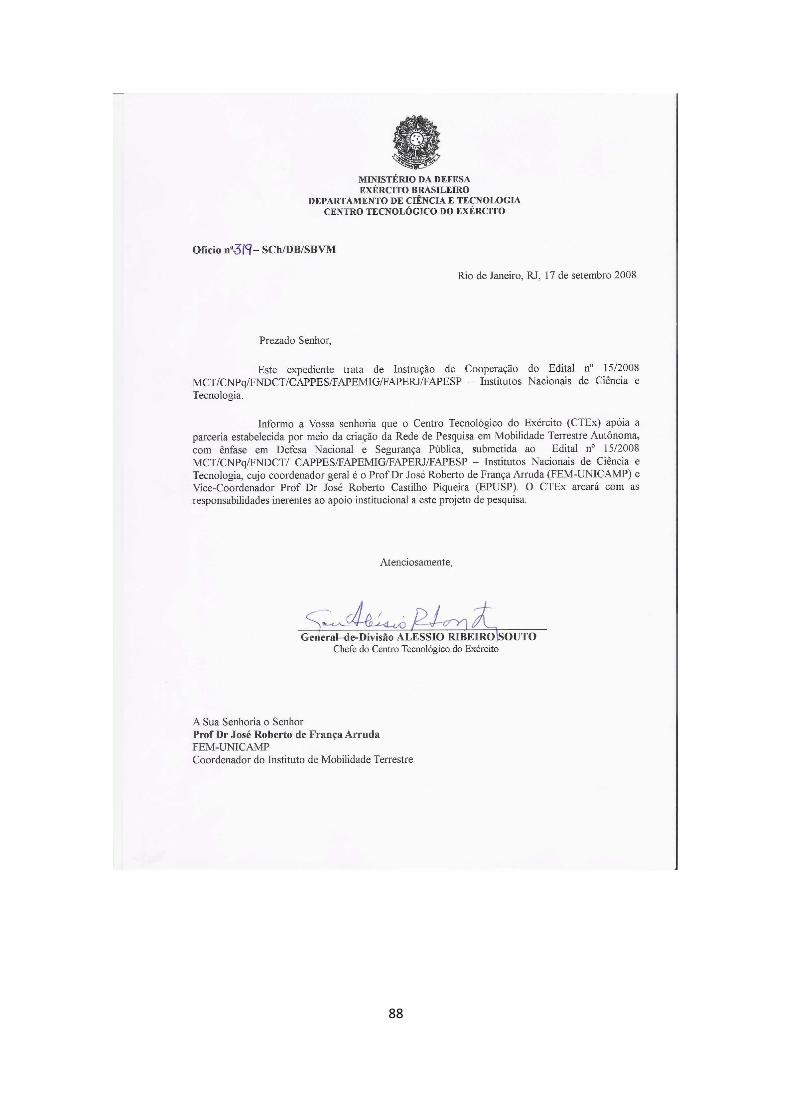
88
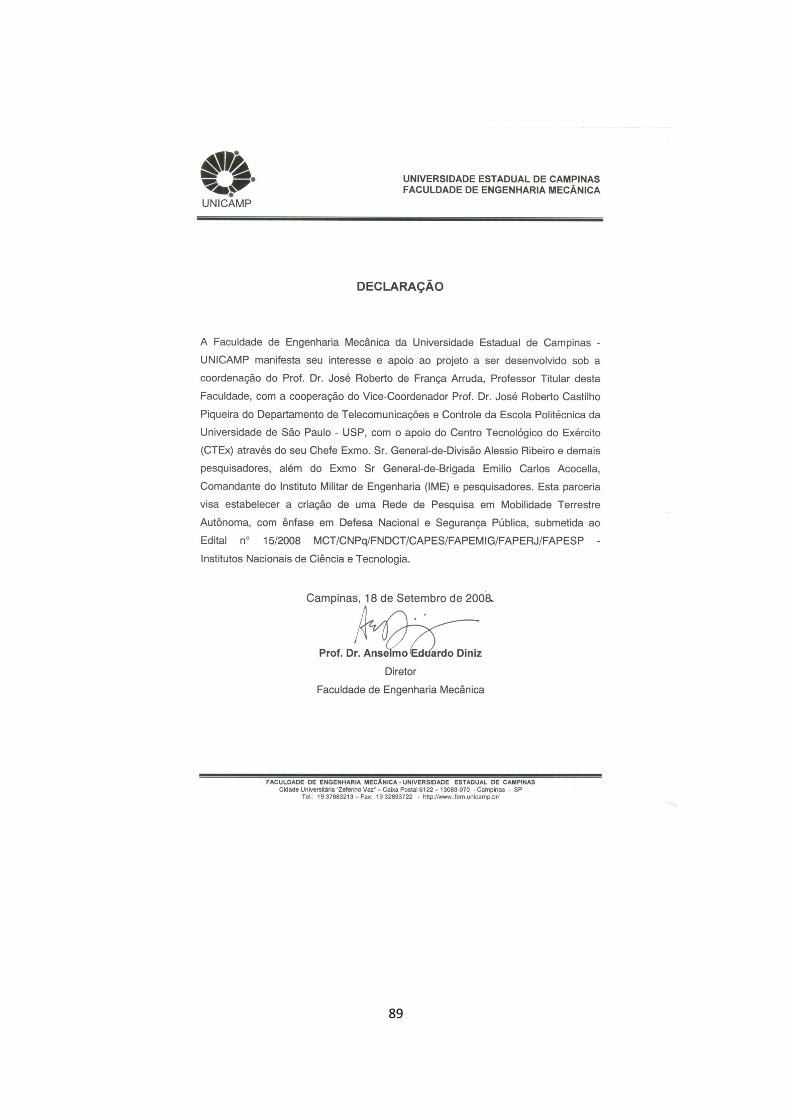
89
90
91
92
93

ANUÊNCIAS DOS PESQUISADORES
94
95
96
97
98
99
100
101
102
103
104
105

106
107
108
109
110
111
112

REFERÊNCIAS BIBLIOGRÁFICAS
113
Bibliografia (Bibliography) [1] CAZANGI, R. R. (2004), “Uma Proposta Evolutiva para Controle Inteligente em
Navegação Autônoma de Robôs”, Dissertação de Mestrado, FEEC, Universidade Estadual de Campinas (UNICAMP).
[2] DARPA (2004), “DARPA Grand Challenge Rulebook”, http://www.darpa.mil/grandchallenge05/. [3] DEFESA@NET (2008), “Programa VBTP – Programa Viatura Blindada de
Transporte de Pessoal”, http://www.defesanet.com.br/.
[4] EXÉRCITO BRASILEIRO (2007), Diretrizes do Comandante do Exército, http://www.exercito.gov.br/05notic/paineis/2007/08ago07/diretrizes.pdf.
[5] McCALL J. C. & TRIVEDI, M. M. (2006), “Video-Based Lane Estimation and Tracking for Driver Assistance: Survey, System, and Evaluation”, IEEE TRANSACTIONS ON INTELLIGENT TRANSPORTATION SYSTEMS, VOL. 7, NO. 1, MARCH 2006.
[6] MENDELECK, A., ZAMPIERI, D. E. & MIRANDA NETO, A. (2005), “Sistemas Classificadores Aplicados à Navegação de Robôs Autônomos”, Congresso Brasileiro de Redes Neurais (CBRN 2005), Natal, RN, Brasil.
[7] MINISTÉRIO DA DEFESA DO BRASIL (2008), Diretrizes Ministeriais, https://www.defesa.gov.br/.
[8] MIRANDA NETO, A. & RITTNER, L. (2006), “A Simple and Efficient Road Detection Algorithm for Real Time Autonomous Navigation based on Monocular Vision”, Proceedings of the 2006 IEEE 3rd Latin American Robotics Symposium (LARS 2006).
[9] MIRANDA NETO, A., RITTNER, L., LEITE, N, ZAMPIERI, D. E., LOTUFO, R., MENDELECK, A. (2007), “Pearson's Correlation Coefficient for Discarding Redundant Information in Real Time Autonomous Navigation Systems”, Proceedings of the 2007 IEEE Multi-conference on Systems and Control.
[10] MIRANDA NETO, A. (2007), “Navegação de Robôs Autônomos baseada em Monovisão”, Dissertação de Mestrado, Universidade Estadual de Campinas (UNICAMP).
[11] SHIROMA, P. M. (2004), “Controle por Visão de Veículos Robóticos”, Dissertação de Mestrado, Instituto de Computação, Universidade Estadual de Campinas (UNICAMP).
[12] STANFORD RACING TEAM’S Entry In The 2005 DARPA Grand Challenge (2006), http://www.stanfordracing.org.
114
[13] TEAM OSHKOSH (2007), “TERRAMAX - DARPA URBAN CHALLENGE”, http://www.terramax.com/technology/the_brawn.cfm.
[14] THRUN, S., MONTEMERLO, M., STAVENS, D., DAHLKAMP, H., et. al. (2005), “Stanford Racing Team’s Entry in the 2005 DARPA Grand Challenge.”, Technical Report: DARPA Grand Challenge.
[15] BEKIR, E. Introduction to Modern Navigation Systems. World Scientific, 2007. [16] DE SOUZA PINTO, J. L. Implementação de uma Metodologia para Avaliação do Desempenho em Sistemas Inerciais Puros. Dissertação de Mestrado, Instituto Militar de Engenharia, 2007. [17] LITMANOVICH, Y. A., LESYUCHEVSKY, V. M. e GUSINSKY, V. Z. Two new classes of strapdown navigation algorithms. Journal of Guidance, Control, and Dynamics, 2000. [18] ROCHA, L. V. Algoritmo de Nivelamento e Alinhamento de um Sistema de Navegação Inercial do Tipo Solidário ("Strapdown". Dissertação de Mestrado, Instituto Militar de Engenharia, 2006. [19] SAVAGE, P. G. Strapdown inertial navigation integration algorithm design part 1: Attitude algorithms. Journal of Guidance, Control and Dynamics, 1998a. [20] SAVAGE, P. G. Strapdown inertial navigation integration algorithm design part 2: Velocity and position. Journal of Guidance, Control and Dynamics, 1998b. [21] SHIN, E.-H. Accuracy Improvement of Low Cost INS/GPS for Land Applications. Dissertação de Mestrado, University of Calgary, 2001. [22] PICADO, R. M. ; MEIRELLES, P. S. . Controle semi-ativo de suspensões automotivas. In: COBEM97 - Congresso Brasileiro de Engenharia Mecânica, 1998, Bauru. Anais do XIV COBEM. Bauru, SP, 8-12/12/97., 1998. v. CD. p. 491 [23] MEIRELLES, P. S. ; PICADO, R. M. . Controle semi-ativo para dissipação de energia. In: V Congresso de Engenharia Mecânica Norte-Nordeste, 1998, Fortaleza CE. [24] Ricardo Migueis Picado. Controle Semi Ativo em Suspensões Automotivas, 1998. Dissertação (Mestrado em Engenharia Mecânica) - Universidade Estadual de Campinas. [25] Alessandro Martini Gemigniani Correia. Modelamento e simulação de uma suspensão hidropneumática. 1999. [26] Sérgio Issamu Matsumoto. Controle Adaptativo de uma Plataforma Hidráulica de uma Colhedora Automotriz. 2000. Dissertação (Mestrado em Engenharia Mecânica) - Universidade Estadual de Campinas.
115
[27] Antonio Fernando Abreu de Andrade. Controle de Suspensões Ativas Utilizando Redes Neurais. 2001. Dissertação (Mestrado em Engenharia Mecânica) - Universidade Estadual de Campinas. [28] MEIRELLES, P. S. ; BALDI, M. . Damping Behavior in Hydropneumatic Suspension. In: XII SIMEA 2003 Simpósio Internacional de Engenharia Automotiva, 2003, São Paulo. XII SIMEA 2003 Simpósio Internacional de Engenharia Automotiva, 2003. [29] MEIRELLES, P. S. ; BALDI, M. . Analysis of Performance of a Hydropneumatic Suspension System. In: 17th International Congress of Mechanical Engineering - COBEM 2003, 2003, São Paulo. 17th International Congress of Mechanical Engineering - COBEM 2003, 2003. [30] BALDI, M. ; MEIRELLES, P. S. . Hydropneumatic Suspension Design. In: International Design Engineering Technical Conference & Computers and Information in Engineering Conference, 2003, Illinois-Chicago. International Design Engineering Technical Conference & Computers and Information in Engineering Conference, 2003. p. 1-10. [31] Maurício Baldi. Desenvolvimento de um Sistema de Suspensão Hidropneumático para Uso em Máquinas Agrícolas. 2004. Dissertação (Mestrado em Engenharia Mecânica) - Universidade Estadual de Campinas. [32] GONCALVES, A. J. ; MEIRELLES, P. S. . Damping Control in Hydropneumatic Suspension. In: COBEM 2005, 2005, Ouro Preto. 18th International Congress of Mechanical Engineering, 2005. p. 1-8. [33] Roberto Luis de Sá. Controle Robusto Aplicado a um Modelo de Suspensão Hidropneumática para Carretas Agrícolas. 2006. Dissertação (Mestrado em Engenharia Mecânica) - Universidade Estadual de Campinas. [34] O. Altet, X. Moreau, M. Moze, P. Lanusse and A. Oustaloup: .Principles and Synthesis of Hydractive CRONE Suspension, Nonlinear Dynamics, Volume 38, Numbers 1-2 / December, 2004, pp. 435-459.
116
Referências (References) • Montgomery, J.: “Autonomous Vision Guided Safe and Precise Landing”,
Automated Reasoning PI Workshop, 4, September 2002, NASA, USA. • Malcolm, A. A.; Lim, J. S. G.: “Teleoperation Control for a Heavy-Duty Tracked
Vehicle”, STR/03/042/PM. • Sadhukhan, D.: “Autonomous Ground Vehicle Terrain Classification Using
Internal Sensors”, M. Sc. Thesis, Florida State University, 2004. • Cremean, L.B. et all: “Alice: An Information-Rich Autonomous Vehicle for High-
Speed Desert Navigation”, J. of Field Robotics, 2006. • Yamauchi, B.: “The Wayfarer Modular Navigation Payload for Intelligent Robot
Infrastructure”, iRobot Research Group. • Murphy, K. et all: “Ground Vehicle Controla t NIST: from Teleoperation to
Autonomy”, 7th Annual Space Operations, Applications, and Research Symposium, Houston, TX, 1993.
• Murphy, K.; Legowik, S.: “GPS Aided Retrotraverse for Unmanned Ground Vehicles”, SPIE 10th Annual AeroSense Symposium, Orlando, FL, 1996.
• Bostelman, R. et all: “Performance Analysis of Unmanned Vehicle Position and Obstacle Maping”, SPIE 06, Defense and Security Symposium, Orlando, FL, 2006.
• Crane III, C. D. et all: “Team CIMAR’s NaviGATOR: An Unmanned Ground Vehicle for Application to the 2005 DARPA Grand Challenge”.
• Crane III, C. D. et all: “Autonomous Ground Vehicle Technologies applied to the DARPA Grand Challenge”, ICCAS2004, Bangkok, Thailand, 2004.
• Mason, R. et all: “The Golem Group/University of California at Los Angeles Autonomous Ground Vehicle in the DARPA Grand Challenge”, J. of Field Robotics 23(8), 527-553, 2006.
• Jones, E. et all: “Autonomous Off-Road Driving in the DARPA Grand Challenge”.
• LeCun, Y. et all: “Off-Road Obstacle Avoidance trough End-to-End Learning”. • Travis, W.; Bevly, D. M.: ”Navigation Errors Introduced by Ground Vehicle
Dynamics”. ION GNSS 18th International Technical Meeting, Long Beach, CA, 2005.
• Simone, M. J.: “A Novel Method to Locate Targets Using Active Vision and Robotic Inertial Navigation Data”, M. Sc. Thesis, Virginia Polytechnic Institute and State University, 2006.
• Monda, M. J.: “Hardware Testbed for Relative Navigation of Unmanned Vehicles Using Visual Servoing”, M. Sc. Thesis, Virginia Polytechnic Institute and State University, 2006.
• Juberts, M. et all: “Development and Test Results for a Vision-Based Approach to AVCS”, 26th ISATA, Aachen, Germany, 1993.
• Spofford, J. R. et all: “Overview of the UGV/Demo II Program”, DARPA/OSD Contract DASG60-95-C-0062.
• Hong, T. H. et all: “Na Intelligent World Model for Autonomous Off-Road Driving”.
117
• Hong, T. et all: “Performance Evaluation of Sensors on Mobile Vehicles Using a Large Data Repository and Ground truth”.
• Grinstead, B. et all: “Developing Detailed a priori 3D Models of Large Environments to Aid in robot Navigation Tasks”, Proc. SPIE, Vol. 5422, Orlando, FL, USA, 561-568, 2004.
• Gillula, J.: “Data Fusion from Multiple Sensors: Real-Time Mapping on an Unmanned Ground Vehicle”, 2005 SURF Final Report.
• Lázaro, J. L. et all: “Móbile Robot with Wide Capture Active Laser Sensor and Environment Definition”, J. of Intelligent and Robotic Systems, 30, 227-248, 2001. - Royer, E. et all: “Localization in Urban Environments: Monocular Vision Compared to a Differential GPS Sensor”.
• Sehestedt, S. et all: “Efficient Lane Detection and Tracking in Urban Environments”.
• Dahlkamp, H. et all: “Self-supervised Monocular Road Detection in Deset terrain”.
• Leedy, B. M.: “Two Minds for one Vehicle: A Case Study in Deliberative and Reactive Navigation”, M. Sc. Thesis, Virginia Polytechnic Institute and State University, 2006.
• Sampo, M. et all: “Automatic Steering System for an Unmanned Vehicle”, US Patent 5,923,270, 1999.
• Monda, M. J.; Schaub, H.: “Hardware Simulation of Relative Navigation Using Visual Sensor Information“, AIAA Guidance, Navigation and Control Conference, San Francisco, CA, 2005.
• Ikeuchi, Y. et all: “The Guidance Subsystem of a Remotely Controlled Autonomous Robot in the Physical Agent System (PAS)”, 2004 IEEE International Workshop on Robot and Human Interactive Communication, Okayama, Japan, 2004.
• Arana-Arejolaleiba, N. et all: “A Smart Sensor based Visual Landmarks Detection for Indoor Robot Navigation”, 2002 IEEE, 1051-4651/002.
• Schempf, H.: “Pandora: Autonomous Urban Robotic Reconnaissance System”, 1999 IEEE, 0-7803-5180-0-5/99.
• Durrant-Whyte, H.: “A Critical Review of the State-of-the-Art in Autonomous Land Vehicle Systems and Technology”, Sandia Report SAND2001-3685, Livermore, CA, USA, 2001.
• Grinstead, B et all: “A Comparison of Pose Estimation Techniques: Hardware vs. Video”, Proc. SPIE Unmanned Ground Vehicle Technology VII, Vol. 5804, Orlando, FL, 2005.
• Brown, A. K.: “Test Results of a GPS/Inertial Navigation System using a Low Cost MEMS IMU”, Proc.11th Annual Saint Petersburg Int. Conf. on Integrated Navigation System, Saint Petersburg, Russia, 2004.
• Bonin-Font, F.; Ortiz, A.; Oliber, G.: “Visual Navigation for Mobile Robots: A Survey”, J. Intell. Robot Syst., DOI 10.1007/s10846-008-9235-4, 2008.
• Lenain, R.; et all: High accuracy path tracking for vehicles in presence of sliding: Application to farm vehicle automatic guidance for agricultural tasks, Auton Robot (2006) 21: 79-97.
• Torii, T.: Research in autonomous agriculture vehicles in Japan, Computer and Eletronics in Agriculture (2000) 25: 133-153.
118
• Schäfer, H; Berns, K.; RAVON-An autonomous Vehicle for Risky Intervention and Surveilleance, Robotics research Lab, University of Kaiserslautern, May 2006.
• Barawid Jr, O. C.; et all: Development of an Autonomous Navigation System using a Two-dimensional Laser Scanner in an Orchard Application, Biosystems Engineering (2007) 96(2): 139-149.
• Fang, H.; et all: Trajectory tracking control of farm vehicles in presence of slinding, Robotics and Autonomous Systems (2006) 54: 828-839.
• Subramanian, V.; et all: Development of machine vision and laser radar based autonomous vehicle guidance systems for citrus grove navigation, Computers and Eletronics in Agriculture (2006) 53: 130-143.
• Pessin, G.: Evolução de Estratégias e Controle Inteligente em Sistemas Multi-Robóticos Robustos, Dissertação de Mestrado, Unisinos (2008).
• Moore, K. L.; Torrie, M.: An Autonomous Orchard Spraying System: Mission Planning and Control, DaNet Thematic Workshop, Horsens, Denmark (2003).
• Bakker, T.; et all: A vision based row detection system for sugar beet, Computers and Eletronics in Agriculture (2008) 60: 87-95.
• Eaton, R.; et all: Precision Guidance of Agricultural Tractors for Autonomous farming, SysCon 2008, Montreal, Canada, April 2008.
• Shen, Y.; et all: Double-Fuzzy Kalman Filter Based on GPS/IMU/MV Sensor Fusion for Tractor Autonomous Guidance, IEEE Int. Conf. on Automation and Logistics, Jinan, China, August 2007.
• Murphy, C.; et all: Low-Cost Stereo Vision on an FPGA, 2007 Int. Symp. On field-Programmable Custom Computing Machines.
• Katupitiya, J.; et all: Systems Engineering Approach to Agricultural Automation: New Developments, IEEE Systems Conference, Hawaii, USA, April 2007.
• Guo, Y.; et all: Vision-Based Drivable Surface Detection in Autonomous Ground Vehicles, IEEE Int. Conf. on Intelligent Robots and Systems, Beijing, China 2006.
• Katupitiya, J.; et all: Automation of an Agricultural Tractor for Fruit Picking, IEEE Int. Conf. on Robotics and Automation, Barcelona, Spain, April 2005.
• Eicker, P.: The Embudito Mission: A Case Study of the Systematics of Autonomous Ground Mobile Robots, Sandia National Labs., 2001.
• Fontaine, V.: Development of a Vision-Based Local Positioning System for Weed Detection, M. Sc. Thesis, University of Saskatchewan, Canada, 2004.
• de Sousa, R. V.; et all: Caracterização de Sensor Ultrassônico para Sistema de Guiagem e Navegação de Veículo Agrícola Autônomo, V Cong. Bras. Agroinformática, Londrina, PR, Setembro 2005.
• de Sousa, R. V.; et all: Proposta de Análise de Redes CAN para Suporte ao Desenvolvimento de Sistemas Embarcados em Máquinas Agrícolas, V Cong. Bras. Agroinformática, Londrina, PR, Setembro 2005.
• Bell, T.: Precision Robotic Control of Agricultural Vehicles on Realistic Farm Trajectories, Ph. D. Thesis, Stanford University 1999.
• Stentz, A.: Robotic Technologies for Outdoor Industrial Vehicles, Proc. SPIE AeroSense 2001.
• Singh, S: Autonomous Robotic Vehicle for Greenhouse Spraying, M. Eng., University of Florida 2004.
119
• Grift, T.; et all: Development of Autonomous Robots for Agricultural Applications, Robotics UIUC Conf.
• Fountas, S.; et all: Decomposition of Agricultural Tasks into Robotic Behaviours, CIGR Ejournal, October 2007.
• Nistala, G. J.: Development of an Inexpensive Guidance System for Agricultural Purposes, M. Sc. Thesis, Louisiana State University 2006.
• Hellström, T.: Autonomous Navigation for Forest Machines, Umea University, Sweden, 2002.
• O’Connor, M. L.: Carrier-Phase Differential GPS for Automatic Control of Land Vehicles, Ph. D. Thesis, Stanford University 1997.
• Wilson, J. N.: Guidance of agricultural vehicle – a historical perspective, Computer and Eletronics in Agriculture (2000) 25: 3-9.
• Edan, Y.: Design of an Autonomous Agricultural Robot, Applied Intelligence (1995) 5: 41-50.
• Stuart Ray, S.: Development of an Autonomous Vehicle for Use in Agriculture, M. Sc. Thesis, Noth Carolina State University 2004.
• Griepentrog, H. W.; et all: Autonomous Inner-Row Hoeing using GPS-based side-shift Control, CIGR Ejournal, July 2007.
• Khurshid, J.; Bing-rong, H.: Military Robots – A Glimpse from Today and Tomorrow, Int. Conf. on Control, Automation, Robotics and Vision, Kunming, China, December 2004.
• Carmer, D. C.; Peterson, L. M.: Laser Radar in Robotics, Proc. IEEE, (1996) 84(2): 299-320.
• Durrant-Whyte, H.: A Critical Review of the State-of-Art in Autonomous Land Vehicle Systems and Technology, Sandia National Labs, 2001.
• Blackmore, S.; et all: A Specification of Behavioural Requirements for an Autonomous Tractor, 6th Int. Symp. On Fruit, Nut an Vegetable Prod. Eng. Conf., Potsdam-Bornim, Germany, July 2002.
• Ellenrieder, K.: Design of an autonomous agricultural vehicle, M. Ph., Cranfield University 1996.
• Roger S. Pressman:Software Engineering: A Practitioner's Approach, The McGraw-Hill Companies, ISBN: 007301933X
• Mark Hoffman & Ted Beaumont: Application Development: Managing the Project Life Cycle, Mc Press, ISBN-10: 1883884454
• Boris Beizer: Software Testing Techniques. Second Edition, International Thomson Computer Press, 1990, ISBN 1-85032-880-3
• Staab, T. C. 2002, “Using SW-TMM to Improve the Testing Process”, Wind Ridge International.
• Sommerville, I., Engenharia de Software, 6a Edição, Addison Wesley, 2003. The V-Model as Software Development Standard. Disponível em: http://www.v-modell.iabg.de/kurzb/vm/k_vm_e.doc. Acessado em setembro de 2008.
• Haykin, S. (2001), “Redes Neurais: Princípios e Prática” – Bookman. • I.j. Nagrath, Laxmidhar Behera, K. Madhava Krishna, and K. Deepak Rajasekar,
(1997), Real-Time Navigation of a Mobile Robot using Kohonen‘s Topology Conserving Neural Network, IEEE 1997.
120
• Huosheng Hu and Dongbing Gu (1999), Landmark-based Navigation of mobile Robots in Manufacturing, IEEE International Conference on Emerging Technologies & Factory Automation, UPC, Barcelona, Spain, 18-21 October 1999.
• Valentin Dimakov and Vladimir Golovko (2000), Self-organizing path Planning Control System for a Vehicle; Proceeding of the ICSC Symposia on Neural Computation (nc'2000) may 23-26, 2000 in Berlin, Germany. Icsc Academic Press, 2000.
• S. Yamada (2004), Recognizing Environments from Action Sequences Using Self-organizing Maps, Elsevier, Applied Soft Computing i (4) 35-47.
• Masumi Ishikawa, Kazuo Ishii, Takeshi Yamakawa, Masahiro Nagamatsu, Hideki Nakagawa, Hong Zhang, Tetsuo Furukawa (2007), Brain-inspired Emergence of Behaviors in Mobile Robots, Elsevier, International Congress Series 1301 48–51, 2007.
• Sousa, R. V., Inamasu, R. Y., Torre Neto, A. (2001), "CAN (Controller Area Network): Um Padrão Internacional de Comunicação de Transdutores Inteligentes para Máquinas Agrícolas", Ministério da Agricultura, Pecuária e Abastecimento - Embrapa, ISSN 1517-4778.
• Von Zuben, F. & Attux, R. (2008), “Notas de Aula de Redes Neurais Artificiais”, FEEC – Universidade Estadual de Campinas (UNICAMP), http://www.dca.fee.unicamp.br/~attux/ia353_a.htm.
• Görzig, S. & Franke, U. (1998), “ANTS - Intelligent Vision In Urban Traffic”, In 1998 IEEE International Conference on Intelligent Vehicles, pages 545-549, October 1998.
• Görzig, S. (2001), “CPPvm - Parallel Programming in C++”, In Third IEEE International Conference on Cluster Computing, October 2001.
• Tanenbaum, A. S. & Van Steen, M. (2002), Distributed Systems: Principles and Paradigms.
• Anuário Estatístico do Departamento Nacional de Transito DENATRAN - RENAEST 2006, www.denatran.gov.br - Portal RENAEST.
• Roxo, e. & Bois, M. (2006), “A Mortalidade em Acidentes de Trânsito no Brasil”, Monografia apresentada à Associação Brasileira de Medicina do Tráfego – ABRAMET.
• Melione, L.P.R., “Morbidade hospitalar por causas externas no Sistema Único de Saúde em São José dos Campos, SP”, Dissertação de Mestrado, USP, 2006.
• Evans, L. (1991), “Traffic Safety and the Driver”, Editora Van Nostrand Reinhold.
• “European Truck Accident Causation”, International Road Transport Union (IRU), 2007.
• Cheng,H., Zheng,N., Zhang,X., et al (2007), “Interactive Road Situation Analysis for Driver Assistance and Safety Warning Systems: Framework and Algorithims”, IEEE Transactions on Intelligent Transportation Systems, vol. 8, nr 1, pag. 157-167.
• Aufrere,R., Gowdy,J.,Mertz,C. et al (2003), “Perception for Collision Avoidance and Autonomous Driving”, Carnegie Mellon University.
• Laplant, P. (2004), “Real-Time System Design and Analysis”, IEEE Press, 3nd ed.
121
• Kim, S., Kang, J., Oh, S., et al (2007), “An Intelligent and Integrated Driver Assistance System for Increased Safety and Convenience Based on All-around Sensing”, Springer Science.
• Miranda Neto, A., Zampieri, D., (2008) Sistema de Navegação Semi-Autônomo de Assistência ao Condutor (SAC), UNICAMP.
• Página da Internet da revista Quatro Rodas, acessada em 04 de maio de 2008, http://quatrorodas.abril.com.br/carros/testes/conteudo_140840.shtml.
• Almeida, J.R., (2008) “Notas de aula da matéria PCS5761, Sistemas de Tempo Real”, Escola Politécnica da USP.
PROJECT IN ENGLISH:
RESEARCH NETWORK IN AUTONOMOUS
TERRESTRIAL MOBILITY WITH FOCUS ON
NATIONAL DEFENSE AND PUBLIC SAFETY
TERRESTRIAL MOBILITY INSTITUTE
122
Rationale
Introduction
Helping people with automated systems, autonomous and semi-autonomous is
a trend that is a result of technological developments. However, to accomplish some
tasks, for example, displacements in urban area, there is a variable of great importance
and impact: the environment. Even in an environment that was previously mapped by
a global positioning system, the randomness and the constant replacements will
modify it partially or totally.
Currently, the search in the area of navigation, autonomous and semi-
autonomous has motivated many researchers from different groups because of the
challenge it represents. It is really important to notice the number of publications in
recent years, incorporating the developments in the area of telematics (MIRANDA
NETO, 2007).
From some guidelines of the U.S. government a few years ago, an agency of
research known as DARPA (Defense Advanced Research Projects Agency) has been
promoting excellent results in the area of autonomous navigation. This agency is the
main body of research of the U.S. Department of Defense and its main task is to
maintain the technological superiority of the American army preventing it from a
technology surprise that could harm the national security.
Thus, since 2002 the DARPA has been encouraging universities, colleges and
businesses in and outside the U.S. to develop autonomous vehicles, because one of the
aims of the American government is transforming one third of its fleet in autonomous
military vehicles in 2015.
As a result of this, in 2004 and 2005 they organized a challenge known as
Grand Challenge. In the first time in 2004, none of the teams managed to successfully
completing the course set out for the competition. In 2005 five teams completed the
challenge, with the winning team at Stanford University, Stanford Racing. In
connection with the Grand Challenge 2005, the challenge was the crossing of the
Mojave desert. The winning team completed the race with an average speed of 30.7
km / h.
123
The last challenge occurred in November 2007. Known as DARPA Urban
Challenge, this challenge was characterized by autonomous vehicles that managed
their missions in a false urban area, operation of extreme importance for the American
army. The stages of the challenge were subdivided into a number of steps for
qualification, which led to a final event that happened in Victorville, CA. Thirty-five
teams were semi finalist, eleven were finalists and the first place was won by the
team called Tartan Racing, Pittsburgh, PA, the second place was won by the Stanford
Racing team, Stanford, CA and the third place was the Victor Tango, Blacksburg,
VA.
During the urban challenge it was possible to test the ability of vehicles to
operate safely and effectively, interacting with other vehicles in and around an urban
environment. The journey took a total distance of approximately 96 km and should be
completed within a period of up to 6 hours. Besides the duty to follow the traffic laws
of the place, the teams had more challenges: variations in the quality of the surface of
roads and paths, obstacles such as: medium-wire, barrels of trafficking, hydrants,
rocks, construction equipment, high-wire tension, in addition to other stationary
obstacles encountered in an urban environment. A further difficulty was the
possibility of blockades were erected during the course of the event, in addition to
interference with the sensor signal GPS (Global Positioning System) caused by trees
and buildings along the route.
It is possible to see how bold is the plan of the U.S Department of Defense,
but in an approximately five years time, the results obtained in the Grand Challenge
challenges and Urban Challenge can make a great progress in this direction.
Moreover, in recent years there has also been a large increase research on the
development of intelligent vehicles, but with a focus on human user. Research on
human-factors has been merged with the investigation of intelligent vehicles, aiming
to create a new generation of Driver-Assistance Systems, which go beyond the
automated control to try to work harmonically with a human operator. There are
emerging systems that can monitor the driver state, provide the intention of the driver,
alert drivers, and help in guiding vehicle. (McCALL & TRIVEDI, 2006).
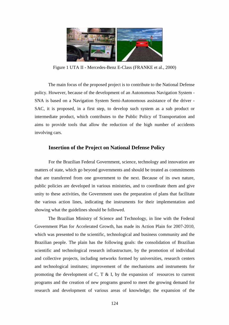
124
Figure 1 UTA II - Mercedes-Benz E-Class (FRANKE et al., 2000)
The main focus of the proposed project is to contribute to the National Defense
policy. However, because of the development of an Autonomous Navigation System -
SNA is based on a Navigation System Semi-Autonomous assistance of the driver -
SAC, it is proposed, in a first step, to develop such system as a sub product or
intermediate product, which contributes to the Public Policy of Transportation and
aims to provide tools that allow the reduction of the high number of accidents
involving cars.
Insertion of the Project on National Defense Policy
For the Brazilian Federal Government, science, technology and innovation are
matters of state, which go beyond governments and should be treated as commitments
that are transferred from one government to the next. Because of its own nature,
public policies are developed in various ministries, and to coordinate them and give
unity to these activities, the Government uses the preparation of plans that facilitate
the various action lines, indicating the instruments for their implementation and
showing what the guidelines should be followed.
The Brazilian Ministry of Science and Technology, in line with the Federal
Government Plan for Accelerated Growth, has made its Action Plain for 2007-2010,
which was presented to the scientific, technological and business community and the
Brazilian people. The plain has the following goals: the consolidation of Brazilian
scientific and technological research infrastructure, by the promotion of individual
and collective projects, including networks formed by universities, research centers
and technological institutes; improvement of the mechanisms and instruments for
promoting the development of C, T & I, by the expansion of resources to current
programs and the creation of new programs geared to meet the growing demand for
research and development of various areas of knowledge; the expansion of the
125
National Network of Education and Research (RNP), to link the entities of the
National System of Education, Science, Technology and Innovation; consolidation of
MCT units of research on condition of national laboratories or core coordinators of
thematic networks in strategic areas for the country autonomous development,
stimulating association with these state and municipal units of P, D & I.
Moreover, it also intends to promote research and development of technologies
focused on the priorities of the National Policy of Defense and public safety, by
supporting the infrastructure of research institutions of science and technology - the
ICT's areas, the training of human resources, and innovation in domestic companies.
It will be also supported partnerships between ICT and public agencies for the
formulation, implementation and evaluation of public policies of security and crime
combat.
The science, technology and innovation are in the contemporary world
scenario, fundamental tools for development, economic growth, employment and
democratization of opportunities . The work of technicians, scientists, researchers and
academics and the engagement of many companies are determining factors for the
consolidation of a model of sustainable development, capable of meeting the just
demands of the Brazilian social and permanent strengthening of national sovereignty.
Again, this is a matter of state, which goes beyond governments.
The document that this project is submitted to has priority themes that have
direct relationship with the strategic areas of the action plan in C, T & I, including
itself the National Defense.
In Brazil, there are guidelines to incentive scientific research in the area of
National Defense. Regarding the area of Science, Technology and Innovation, the site
of the Ministry of Defense announces that the ministry has the mission of enabling
solutions and scientific-technological innovations to meet the needs of the country
pertaining to Defense and national development. Thus, a design of National Defense
interest areas was created, and the detailing of these strategic is bounded by three axes
that are able to create vectors and coordinated, called Technology for National
Defense of Interest:
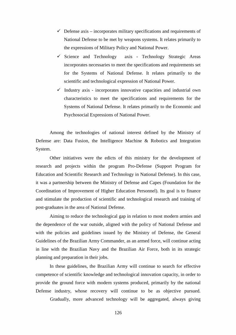
126
� Defense axis – incorporates military specifications and requirements of
National Defense to be met by weapons systems. It relates primarily to
the expressions of Military Policy and National Power.
� Science and Technology axis - Technology Strategic Areas
incorporates necessaries to meet the specifications and requirements set
for the Systems of National Defense. It relates primarily to the
scientific and technological expression of National Power.
� Industry axis - incorporates innovative capacities and industrial own
characteristics to meet the specifications and requirements for the
Systems of National Defense. It relates primarily to the Economic and
Psychosocial Expressions of National Power.
Among the technologies of national interest defined by the Ministry of
Defense are: Data Fusion, the Intelligence Machine & Robotics and Integration
System.
Other initiatives were the edicts of this ministry for the development of
research and projects within the program Pro-Defense (Support Program for
Education and Scientific Research and Technology in National Defense). In this case,
it was a partnership between the Ministry of Defense and Capes (Foundation for the
Coordination of Improvement of Higher Education Personnel). Its goal is to finance
and stimulate the production of scientific and technological research and training of
post-graduates in the area of National Defense.
Aiming to reduce the technological gap in relation to most modern armies and
the dependence of the war outside, aligned with the policy of National Defense and
with the policies and guidelines issued by the Ministry of Defense, the General
Guidelines of the Brazilian Army Commander, as an armed force, will continue acting
in line with the Brazilian Navy and the Brazilian Air Force, both in its strategic
planning and preparation in their jobs.
In these guidelines, the Brazilian Army will continue to search for effective
competence of scientific knowledge and technological innovation capacity, in order to
provide the ground force with modern systems produced, primarily by the national
Defense industry, whose recovery will continue to be as objective pursued.
Gradually, more advanced technology will be aggregated, always giving
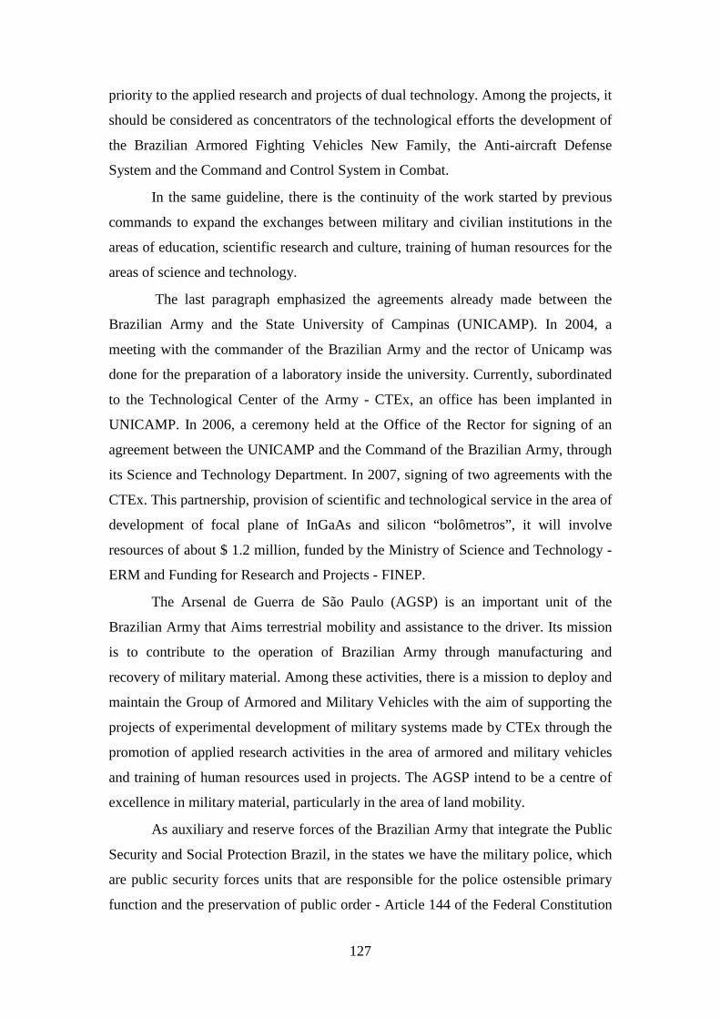
127
priority to the applied research and projects of dual technology. Among the projects, it
should be considered as concentrators of the technological efforts the development of
the Brazilian Armored Fighting Vehicles New Family, the Anti-aircraft Defense
System and the Command and Control System in Combat.
In the same guideline, there is the continuity of the work started by previous
commands to expand the exchanges between military and civilian institutions in the
areas of education, scientific research and culture, training of human resources for the
areas of science and technology.
The last paragraph emphasized the agreements already made between the
Brazilian Army and the State University of Campinas (UNICAMP). In 2004, a
meeting with the commander of the Brazilian Army and the rector of Unicamp was
done for the preparation of a laboratory inside the university. Currently, subordinated
to the Technological Center of the Army - CTEx, an office has been implanted in
UNICAMP. In 2006, a ceremony held at the Office of the Rector for signing of an
agreement between the UNICAMP and the Command of the Brazilian Army, through
its Science and Technology Department. In 2007, signing of two agreements with the
CTEx. This partnership, provision of scientific and technological service in the area of
development of focal plane of InGaAs and silicon “bolômetros”, it will involve
resources of about $ 1.2 million, funded by the Ministry of Science and Technology -
ERM and Funding for Research and Projects - FINEP.
The Arsenal de Guerra de São Paulo (AGSP) is an important unit of the
Brazilian Army that Aims terrestrial mobility and assistance to the driver. Its mission
is to contribute to the operation of Brazilian Army through manufacturing and
recovery of military material. Among these activities, there is a mission to deploy and
maintain the Group of Armored and Military Vehicles with the aim of supporting the
projects of experimental development of military systems made by CTEx through the
promotion of applied research activities in the area of armored and military vehicles
and training of human resources used in projects. The AGSP intend to be a centre of
excellence in military material, particularly in the area of land mobility.
As auxiliary and reserve forces of the Brazilian Army that integrate the Public
Security and Social Protection Brazil, in the states we have the military police, which
are public security forces units that are responsible for the police ostensible primary
function and the preservation of public order - Article 144 of the Federal Constitution
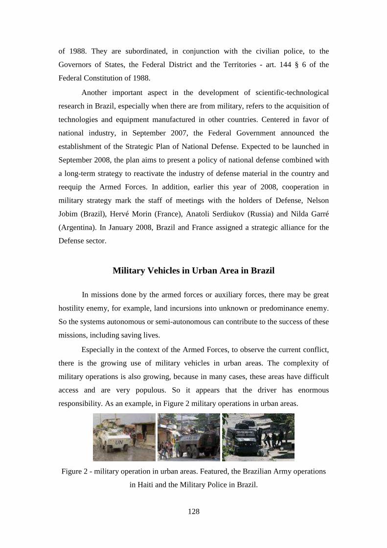
128
of 1988. They are subordinated, in conjunction with the civilian police, to the
Governors of States, the Federal District and the Territories - art. 144 § 6 of the
Federal Constitution of 1988.
Another important aspect in the development of scientific-technological
research in Brazil, especially when there are from military, refers to the acquisition of
technologies and equipment manufactured in other countries. Centered in favor of
national industry, in September 2007, the Federal Government announced the
establishment of the Strategic Plan of National Defense. Expected to be launched in
September 2008, the plan aims to present a policy of national defense combined with
a long-term strategy to reactivate the industry of defense material in the country and
reequip the Armed Forces. In addition, earlier this year of 2008, cooperation in
military strategy mark the staff of meetings with the holders of Defense, Nelson
Jobim (Brazil), Hervé Morin (France), Anatoli Serdiukov (Russia) and Nilda Garré
(Argentina). In January 2008, Brazil and France assigned a strategic alliance for the
Defense sector.
Military Vehicles in Urban Area in Brazil
In missions done by the armed forces or auxiliary forces, there may be great
hostility enemy, for example, land incursions into unknown or predominance enemy.
So the systems autonomous or semi-autonomous can contribute to the success of these
missions, including saving lives.
Especially in the context of the Armed Forces, to observe the current conflict,
there is the growing use of military vehicles in urban areas. The complexity of
military operations is also growing, because in many cases, these areas have difficult
access and are very populous. So it appears that the driver has enormous
responsibility. As an example, in Figure 2 military operations in urban areas.
Figure 2 - military operation in urban areas. Featured, the Brazilian Army operations
in Haiti and the Military Police in Brazil.
129
Apart from agreements between the Brazilian Army and UNICAMP cited
above, the press reported that efforts are being made to facilitate the development of
applied research to public security. In December 2007, a Light Tactical Armoured
Vehicle was presented to the direction of the head of FAPERJ by the commander of
CTEx, General Aléssio Souto Ribeiro. The car is able to resist firing of rifle, with
design more rational, cool and more comfortable, could patrol urban areas and be used
in the displacement of detainees.
The New Family of Armored Fighting Vehicles is another project under the
direction of the Brazilian Army. The Program will be developed by the company
FIAT Automotive SA, the holding company of Fiat Group in Brazil, representing the
Division Iveco.
In the context of vehicles large, in recent challenges of DARPA, the Team
Oshkosh adapted a truck, originally designed for combat, and used by the U.S. Marine
Corps (United States Marine Corps). The vehicle known as TerraMax ™ can be seen
in Figure 3. Besides the intelligent navigation system, among its adjustments, the
original brake system was replaced by an electronic system called Bendix EBS5
Electronic Braking System. This "brake-by-wire" was selected because it allowed the
full autonomous control and manual control for cases of human intervention or any
failure. The control of the engine and transmission has also been adapted to the
protocol J1939, which uses the specification CAN (TEAM OSHKOSH, 2007).
Figure 3 - TerraMax ™, truck built by Oshkosh Team for the 2007 DARPA Urban
Challenge (TEAM OSHKOSH, 2007).
For ordinary citizens, the Driver Assistance Systems - DAS, has also great
importance. For example, because the more complex traffic situations, fractions of a
second can be decisive to avoid traffic accidents, where one of the main factors is the
time for human reaction, in addition to fatigue, distractions and the ability to fall
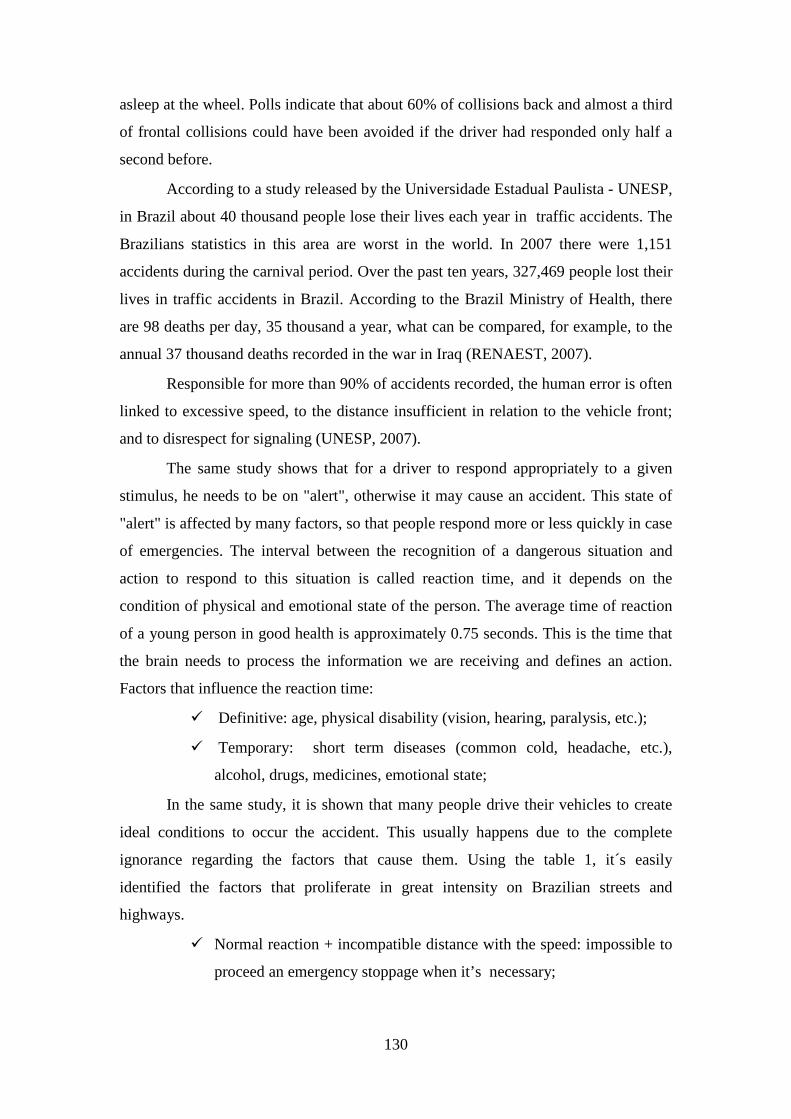
130
asleep at the wheel. Polls indicate that about 60% of collisions back and almost a third
of frontal collisions could have been avoided if the driver had responded only half a
second before.
According to a study released by the Universidade Estadual Paulista - UNESP,
in Brazil about 40 thousand people lose their lives each year in traffic accidents. The
Brazilians statistics in this area are worst in the world. In 2007 there were 1,151
accidents during the carnival period. Over the past ten years, 327,469 people lost their
lives in traffic accidents in Brazil. According to the Brazil Ministry of Health, there
are 98 deaths per day, 35 thousand a year, what can be compared, for example, to the
annual 37 thousand deaths recorded in the war in Iraq (RENAEST, 2007).
Responsible for more than 90% of accidents recorded, the human error is often
linked to excessive speed, to the distance insufficient in relation to the vehicle front;
and to disrespect for signaling (UNESP, 2007).
The same study shows that for a driver to respond appropriately to a given
stimulus, he needs to be on "alert", otherwise it may cause an accident. This state of
"alert" is affected by many factors, so that people respond more or less quickly in case
of emergencies. The interval between the recognition of a dangerous situation and
action to respond to this situation is called reaction time, and it depends on the
condition of physical and emotional state of the person. The average time of reaction
of a young person in good health is approximately 0.75 seconds. This is the time that
the brain needs to process the information we are receiving and defines an action.
Factors that influence the reaction time:
� Definitive: age, physical disability (vision, hearing, paralysis, etc.);
� Temporary: short term diseases (common cold, headache, etc.),
alcohol, drugs, medicines, emotional state;
In the same study, it is shown that many people drive their vehicles to create
ideal conditions to occur the accident. This usually happens due to the complete
ignorance regarding the factors that cause them. Using the table 1, it´s easily
identified the factors that proliferate in great intensity on Brazilian streets and
highways.
� Normal reaction + incompatible distance with the speed: impossible to
proceed an emergency stoppage when it’s necessary;
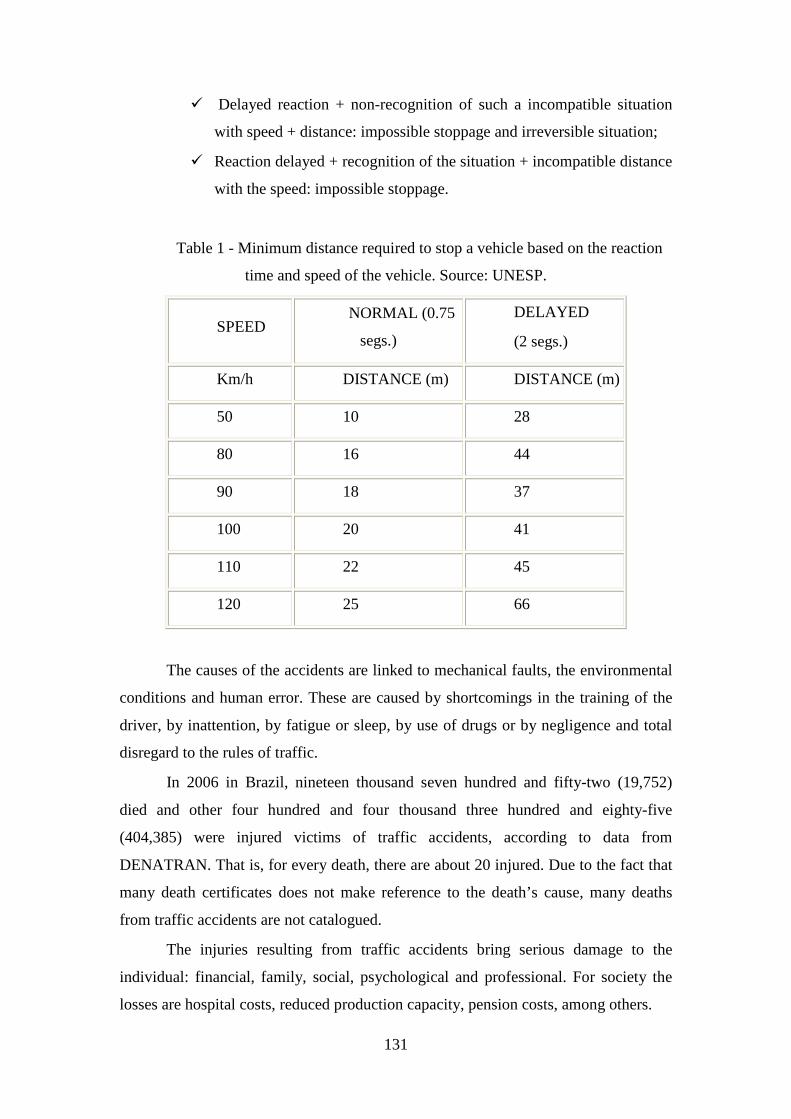
131
� Delayed reaction + non-recognition of such a incompatible situation
with speed + distance: impossible stoppage and irreversible situation;
� Reaction delayed + recognition of the situation + incompatible distance
with the speed: impossible stoppage.
Table 1 - Minimum distance required to stop a vehicle based on the reaction
time and speed of the vehicle. Source: UNESP.
SPEED NORMAL (0.75
segs.)
DELAYED
(2 segs.)
Km/h DISTANCE (m) DISTANCE (m)
50 10 28
80 16 44
90 18 37
100 20 41
110 22 45
120 25 66
The causes of the accidents are linked to mechanical faults, the environmental
conditions and human error. These are caused by shortcomings in the training of the
driver, by inattention, by fatigue or sleep, by use of drugs or by negligence and total
disregard to the rules of traffic.
In 2006 in Brazil, nineteen thousand seven hundred and fifty-two (19,752)
died and other four hundred and four thousand three hundred and eighty-five
(404,385) were injured victims of traffic accidents, according to data from
DENATRAN. That is, for every death, there are about 20 injured. Due to the fact that
many death certificates does not make reference to the death’s cause, many deaths
from traffic accidents are not catalogued.
The injuries resulting from traffic accidents bring serious damage to the
individual: financial, family, social, psychological and professional. For society the
losses are hospital costs, reduced production capacity, pension costs, among others.
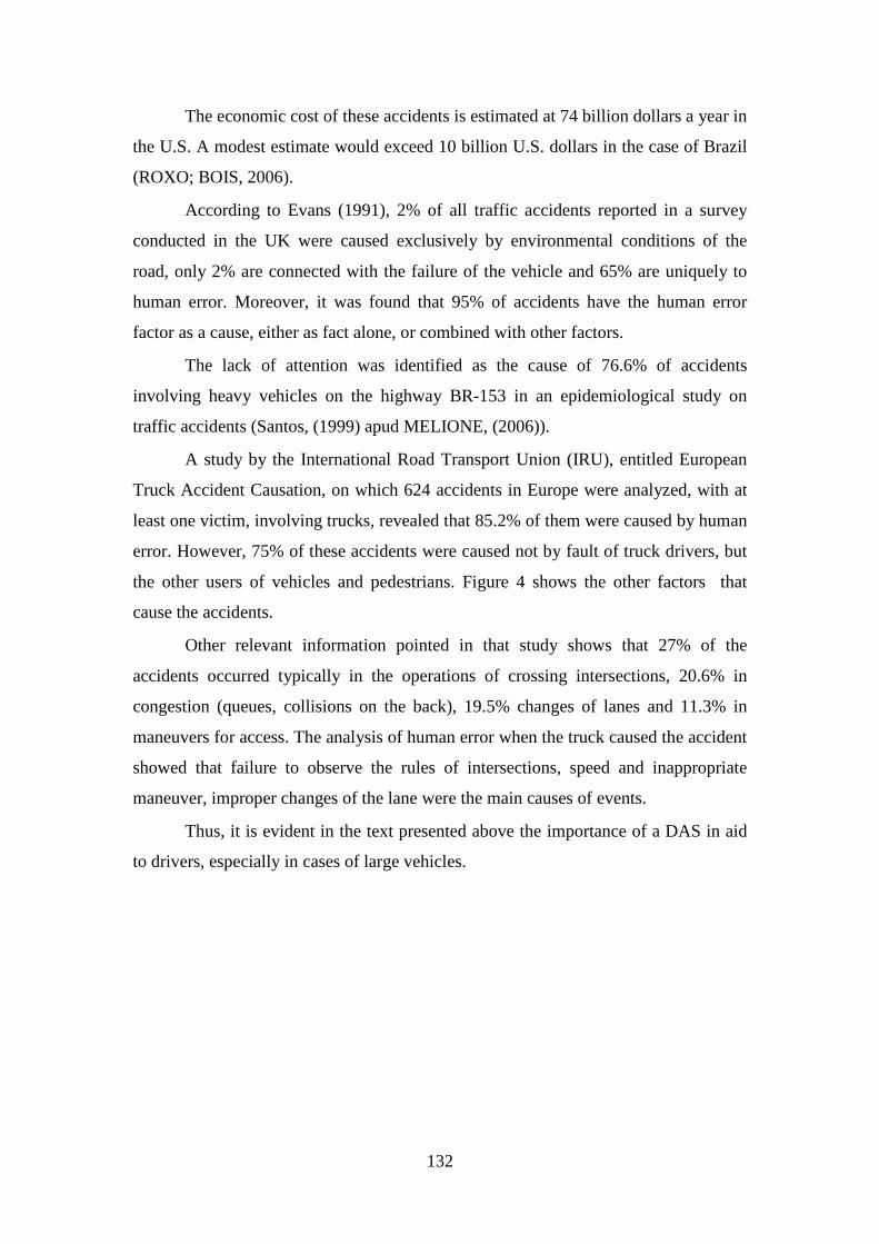
132
The economic cost of these accidents is estimated at 74 billion dollars a year in
the U.S. A modest estimate would exceed 10 billion U.S. dollars in the case of Brazil
(ROXO; BOIS, 2006).
According to Evans (1991), 2% of all traffic accidents reported in a survey
conducted in the UK were caused exclusively by environmental conditions of the
road, only 2% are connected with the failure of the vehicle and 65% are uniquely to
human error. Moreover, it was found that 95% of accidents have the human error
factor as a cause, either as fact alone, or combined with other factors.
The lack of attention was identified as the cause of 76.6% of accidents
involving heavy vehicles on the highway BR-153 in an epidemiological study on
traffic accidents (Santos, (1999) apud MELIONE, (2006)).
A study by the International Road Transport Union (IRU), entitled European
Truck Accident Causation, on which 624 accidents in Europe were analyzed, with at
least one victim, involving trucks, revealed that 85.2% of them were caused by human
error. However, 75% of these accidents were caused not by fault of truck drivers, but
the other users of vehicles and pedestrians. Figure 4 shows the other factors that
cause the accidents.
Other relevant information pointed in that study shows that 27% of the
accidents occurred typically in the operations of crossing intersections, 20.6% in
congestion (queues, collisions on the back), 19.5% changes of lanes and 11.3% in
maneuvers for access. The analysis of human error when the truck caused the accident
showed that failure to observe the rules of intersections, speed and inappropriate
maneuver, improper changes of the lane were the main causes of events.
Thus, it is evident in the text presented above the importance of a DAS in aid
to drivers, especially in cases of large vehicles.
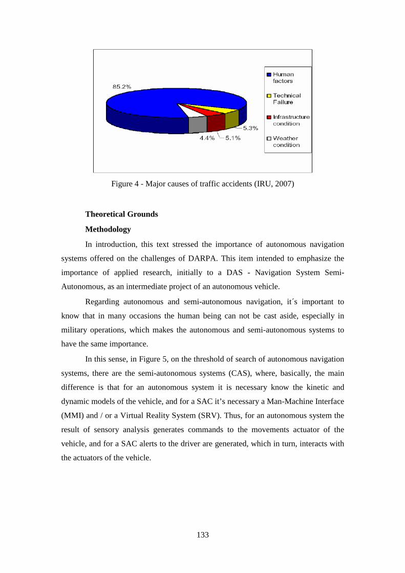
133
Figure 4 - Major causes of traffic accidents (IRU, 2007)
Theoretical Grounds
Methodology
In introduction, this text stressed the importance of autonomous navigation
systems offered on the challenges of DARPA. This item intended to emphasize the
importance of applied research, initially to a DAS - Navigation System Semi-
Autonomous, as an intermediate project of an autonomous vehicle.
Regarding autonomous and semi-autonomous navigation, it´s important to
know that in many occasions the human being can not be cast aside, especially in
military operations, which makes the autonomous and semi-autonomous systems to
have the same importance.
In this sense, in Figure 5, on the threshold of search of autonomous navigation
systems, there are the semi-autonomous systems (CAS), where, basically, the main
difference is that for an autonomous system it is necessary know the kinetic and
dynamic models of the vehicle, and for a SAC it’s necessary a Man-Machine Interface
(MMI) and / or a Virtual Reality System (SRV). Thus, for an autonomous system the
result of sensory analysis generates commands to the movements actuator of the
vehicle, and for a SAC alerts to the driver are generated, which in turn, interacts with
the actuators of the vehicle.
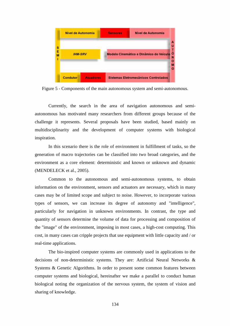
134
Figure 5 - Components of the main autonomous system and semi-autonomous.
Currently, the search in the area of navigation autonomous and semi-
autonomous has motivated many researchers from different groups because of the
challenge it represents. Several proposals have been studied, based mainly on
multidisciplinarity and the development of computer systems with biological
inspiration.
In this scenario there is the role of environment in fulfillment of tasks, so the
generation of macro trajectories can be classified into two broad categories, and the
environment as a core element: deterministic and known or unknown and dynamic
(MENDELECK et al., 2005).
Common to the autonomous and semi-autonomous systems, to obtain
information on the environment, sensors and actuators are necessary, which in many
cases may be of limited scope and subject to noise. However, to incorporate various
types of sensors, we can increase its degree of autonomy and "intelligence",
particularly for navigation in unknown environments. In contrast, the type and
quantity of sensors determine the volume of data for processing and composition of
the "image" of the environment, imposing in most cases, a high-cost computing. This
cost, in many cases can cripple projects that use equipment with little capacity and / or
real-time applications.
The bio-inspired computer systems are commonly used in applications to the
decisions of non-deterministic systems. They are: Artificial Neural Networks &
Systems & Genetic Algorithms. In order to present some common features between
computer systems and biological, hereinafter we make a parallel to conduct human
biological noting the organization of the nervous system, the system of vision and
sharing of knowledge.
135
Regardless of the type of environment, for the passage of people, the nervous
system together with the endocrine system play the control of body functions. This
system receives thousands of information from different sensory organs, and their role
is to integrate them to determine answers to be executed. Its composition can be
traced to the sensory experiences gained through the sensory receptors and may be
hearing from those experiences, visual and bound to touch (GUYTON, 1973).
One of the main functions of the nervous system is to achieve optimal
answers. Much of the information acquired by the sensors are neglected after passing
through the information processor of the brain, and this can be justified, based on the
fact that humans can play various activities simultaneously. As an example, while
driving a vehicle, a person may develop other activities such as talking, thinking about
other things, or even ignore the fact that their skin is in contact with their clothing.
Especially applied to human vision, at any given time, the focus of the vision of one
person can be focused on a specific area of the environment, for example, the road
from where browsing, however, other areas of the environment are not being ignored,
this is, these sub-images of the environment will be delegated the background.
To achieve the storage of information, human beings have the cerebral cortex
and spinal cord. This process of storage can be called a memory. The information to
be stored travel through the synapses, which has very different properties, such as
transmitting a signal of a neuron to another. From the moment that the memories have
been stored in the nervous system, it will become part of the mechanism of
development, or could be used for subsequent motor activities. Such memories are
compared to future new experiences, to assist in the selection of new information
(GUYTON, 1973).
According DURRANT-WHYTE (2001), where he presents a paper about the
state of the art of autonomous vehicles and technologies, this author points out that
five major components must compose an autonomous system, is Mobility, Location,
Navigation, Mission and / or Planning of the task and Communications, of which,
briefly, if describe below.
As it can be seen in Figure 6, the mobility is seen simply as the effect of the
global system, in other words, as the result of observation of the system as a whole.
The location of the site provides information, for example, attitude, speed and
acceleration of the vehicle. The location is an exclusive function of exit in relation to

136
the rest of the system. This means that the increasing the capacity by Location can
often proceed independently of the other system components.
The Navigation is concerned about the acquisition and respond to information
from the external environment. The function of Navigation receives entry as the result
of observation of the sensors in the operational environment. This observation is very
importance, since it creates an internal representation of the environment, which can
be used later during the execution of a mission.
Mission and / or the Task Planning is responsible for generating the
trajectories, behavior and / or points of passage for the system. She has no direct
connection with any controller of entry or exit sensory. However, it must have a clear
understanding of them, in conjunction with the maps read before, possible mission
and objectives to be met in order to produce adequate navigation commands.
The Communication provides the link between the vehicle and all the possible
elements of the global system, including other vehicles and / or operators. There is no
reason to suppose that an autonomous system or (semi)-autonomous should not share
its information with other communication systems, unless the mission requires it
done.
Figure 6 - The relationship between the various functional components of an
autonomous navigation system (DURRANT-WHYTE, 2001).
137
It is noteworthy that despite the high importance of the mission to be met by
an autonomous system, that is, because of the power to influence the details of the
mission under the global system, this fact should not affect the functional elements of
the vehicle, for example, the need for mobility, location, navigation and planning,
which are skills that must be continued regardless the mission.
Indeed, it is hoped that the structure and role of the mission, besides the task of
planning, are a critical function, which allow the insertion of a degree of flexibility.
However, the assessment of specific missions will not be discussed now.
Thus, this is the fulfillment of tasks, if the task of navigation is a known and
static environment, problems can first be reduced to modeling the environment and
search for ways following a criterion for optimization, for example, distance, energy ,
Processing, number of movements, quality of shifts, etc.. For unstructured
environments, the study the scenario is dynamic, with several elements in movements.
Thus, driving a navigation autonomous or semi-autonomous system from a starting
point to your destination, or assist a driver in this task, involving the execution of
complex operations and non-deterministic, as an example: interaction with the
environment, identifying the elements and environmental decision-making. In this
case, the generation of track requires the treatment of a number of unknown factors at
the planning software, such as the volume of desktop and mobile and fixed elements.
Without this information, the computational cost for the generation of path becomes
very high, especially considering the conventional forms of programming robots
(MENDELECK et al., 2005).
Moreover, saying that an agent is autonomous means to say that he acts by
himself, he is supposed to achieve self-regulate generating their own rules governing
their actions. Hence, the definition distinguishes autonomous from automatic, for
being automatic is to be able to operate in an environment realizing it and impacting
it, seeking the fulfillment of tasks defined. An autonomous agent is first of all
automatic, but should drive itself based on ability to learn and adapt their behaviour
(CAZANGI, 2004). But only automatic could not be the ideal classification for a
semi-autonomous system - DAS, for it can operate as it were standalone, leaving only
the final decision to move the driver of the vehicle.
With what we have until now, a DAS can be defined as a system that has the
capacity to understand the environment, administer the aid to compliance with pre-
138
defined tasks and present the result of processing (status) to the driver of the vehicle.
But the existence of levels of autonomy should be considered, because it is a being
totally independent. As an example: animals, in general, and human beings, in
particular, depend on external factors to survive. So when we say that an agent is
autonomous, one should bear in mind that he has certain level of autonomy and that
he is not completely autonomous, and that the more autonomous is the agent, less
foreign aid it needs (CAZANGI, 2004).
Connected to the levels of autonomy included three definitions SHIROMA
(2004):
� System Mechanic - "The physical part. The mobile platform of the
vehicle. It is immersed in a global environment or the real world and is
able to interact with a portion of it - the local environment, for
example: a room, a corridor or a road through its actuators. "
� Sensors - "Give the data from which the state of the robot is
determined."
� Intelligence - "The brain; responsible for the intelligence of system."
Assuming a given level of autonomy, initially, or even as a by-product, this
project proposes the construction of a Navigation System Semi-Autonomous
assistance of the driver - DAS. Through a system of Virtual Reality Simulation -
SRV, initially Non-Immersive for assistance to the driver, your goal will help a driver
during the term of pre-defined tasks are executed in unknown and dynamic
environments. In this way, including the driver, the four components: the driver,
System Mechanic, sensors and intelligence, should interact continuously targeting the
fulfillment of tasks of navigation.
The main goal of this first phase will be the fulfillment of tasks in shifts
between pre-determined points in unstructured environment, from information
provided by a global positioning system. Known the points of origin and destination,
during the shift, the system should be able to identify the area of navigation in relation
to their obstacles, alerting the driver about possible collisions, and learning from the
movements performed.
It appears that this first phase, as presented in Figure 7, the choice of
developing of a SAC made that the kinetic and dynamic models of the vehicle was not
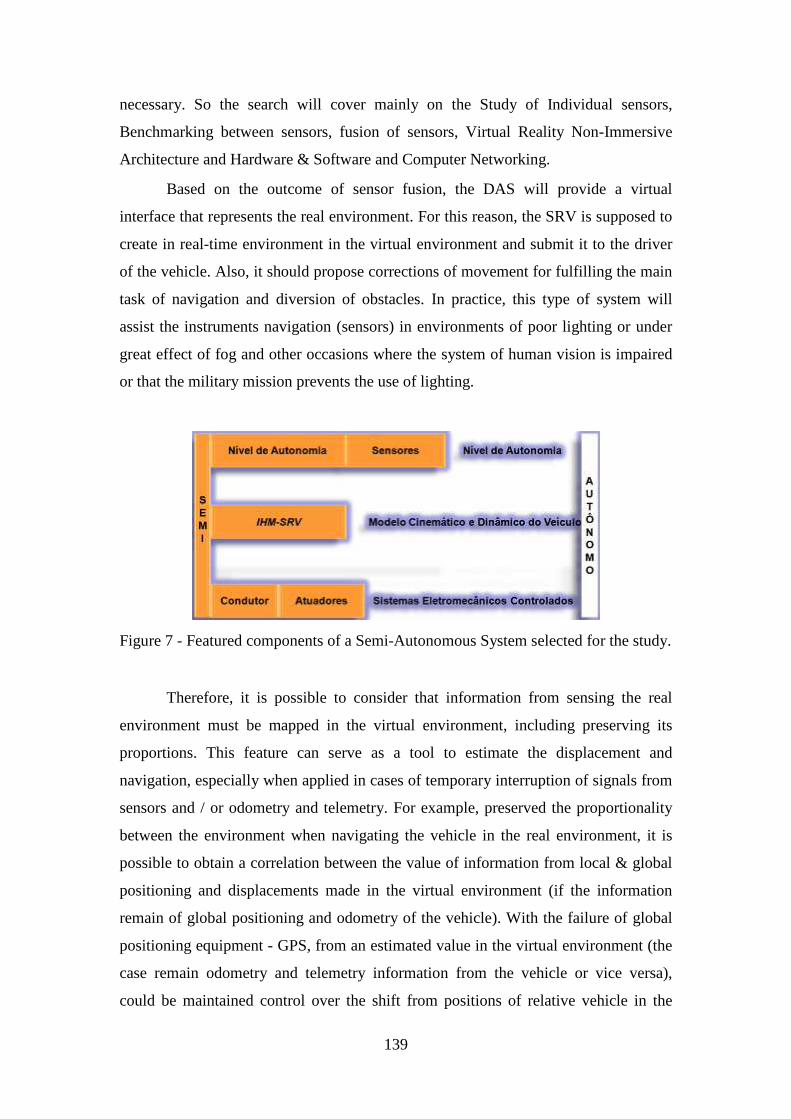
139
necessary. So the search will cover mainly on the Study of Individual sensors,
Benchmarking between sensors, fusion of sensors, Virtual Reality Non-Immersive
Architecture and Hardware & Software and Computer Networking.
Based on the outcome of sensor fusion, the DAS will provide a virtual
interface that represents the real environment. For this reason, the SRV is supposed to
create in real-time environment in the virtual environment and submit it to the driver
of the vehicle. Also, it should propose corrections of movement for fulfilling the main
task of navigation and diversion of obstacles. In practice, this type of system will
assist the instruments navigation (sensors) in environments of poor lighting or under
great effect of fog and other occasions where the system of human vision is impaired
or that the military mission prevents the use of lighting.
Figure 7 - Featured components of a Semi-Autonomous System selected for the study.
Therefore, it is possible to consider that information from sensing the real
environment must be mapped in the virtual environment, including preserving its
proportions. This feature can serve as a tool to estimate the displacement and
navigation, especially when applied in cases of temporary interruption of signals from
sensors and / or odometry and telemetry. For example, preserved the proportionality
between the environment when navigating the vehicle in the real environment, it is
possible to obtain a correlation between the value of information from local & global
positioning and displacements made in the virtual environment (if the information
remain of global positioning and odometry of the vehicle). With the failure of global
positioning equipment - GPS, from an estimated value in the virtual environment (the
case remain odometry and telemetry information from the vehicle or vice versa),
could be maintained control over the shift from positions of relative vehicle in the
140
virtual environment, preserving the performance of tasks. These results also fit the
requirements of systems for reconnaissance and surveillance and observation, when
operated remotely.
In the Grand Challenge challenges and Urban Challenge, organized by
DARPA, to keep the information from positioning to the tasks was a prerequisite of
navigation systems because they were maintaining control over the implementation of
the task regardless of perfect operation of GPS sensor .
For the man-machine relationship may occur, it is essential the use of
interfaces and interactivity. Without these two reasons, it is impossible to have any
kind of man-machine relationship. A Man-Machine Interface - IMH understand the
behavior of the user, software, hardware and the environment - physical locations and
their impacts. Basically, the IMH is the connection between the external image of the
system and man. The interface allows the system to stay in touch with the user, and
the interaction of reciprocal action. The user has a mental model of how the system
works, and the system has a cognitive model of how you will behave.
The Virtual Reality (RV) or virtual environment is a technology interface
between a user and a computer system. Its goal is to recreate the fullest sense of
reality to an individual, leading him to adopt this interaction as one of its temporal
realities. As a prerequisite, it should take place in real time, using computational
techniques and equipment that help in expanding the sense of presence of the user. In
addition, RV as a tool for simulation of reality through technology also extends to a
seizure of a universe not real, a universe of icons and symbols, but in a process of
permeating significance of this false universe.
Originally, the term RV meant a completely immersive system, however, the
word has been used to describe systems that do not use digital components such as
gloves. According to literature, RV non-immersive is performed using a common
display in which the user manipulates the virtual environment through an input
device. Some devices important to RV: sensory perception; Hardware, Software, with
the user interface (simulations in real time). Besides being a good tool for
communication with the user, a simulated environment also allows the development
of simulation environments for testing the navigation system. Tests carried out in real
environment, in general, consume a considerable amount of time and resources of the
team. In addition, environmental changes increase the difficulty of specific tests.
141
It is, furthermore, the use of this research for the development of simulation
systems for the detection of targets in systems of semi-automatic weapons, for
example, using the resources of the Automatic Repair of machine gun, now under
development in the Technology Center of the Army - CTEx.
To facilitate the search, there is the participation of several researchers and
specialists of different institutions. Thus, as well as in papers submitted to DARPA,
on the occasion of the Grand Challenge and Urban Challenge, has been chosen an
architecture based on logic layers (eg, TEAM OSHKOSH, 2007; STANFORD
RACING TEAM'S, 2005).
According TEAM OSHKOSH (2007), this type of architecture facilitates the
separation of functions and development, and allows the definition of the interfaces
between subsystems. This has allowed the team members develop their activities
independently, without sacrificing cohesion of the system. In Figure 6 architecture we
see the logic proposed by Team Oshkosh.
In Figure 8 an adjustment was made to the architecture logic proposed by
Team Oshkosh, excluding, initially, the layers: Control System (Control System) and
Management of the vehicle (Vehicle Management). Basically, drawing up these two
layers, describes itself the product development intermediary, either to assist the
driver, will not be developed when the kinematic and dynamic model of the vehicle,
ie not exist and the mechanisms of self-control actuators vehicle. Then, for the project
autonomous all sections will be used.
From the macro diagram of Figure 9 can be noted that the development of the
proposal should occur in matrix form with some lines of research being developed in
parallel.
Note that the work will develop in two main lines, namely: System Services
and Services Freelancers. The first of them do not need a large infrastructure
laboratory since the virtual reality and human-machine interface will be the main
targets to be achieved and will serve as a critical event for the assessment of
development of the subject.
The second phase, more or less depending on the input of resources to be
performed in a simulated or end use.
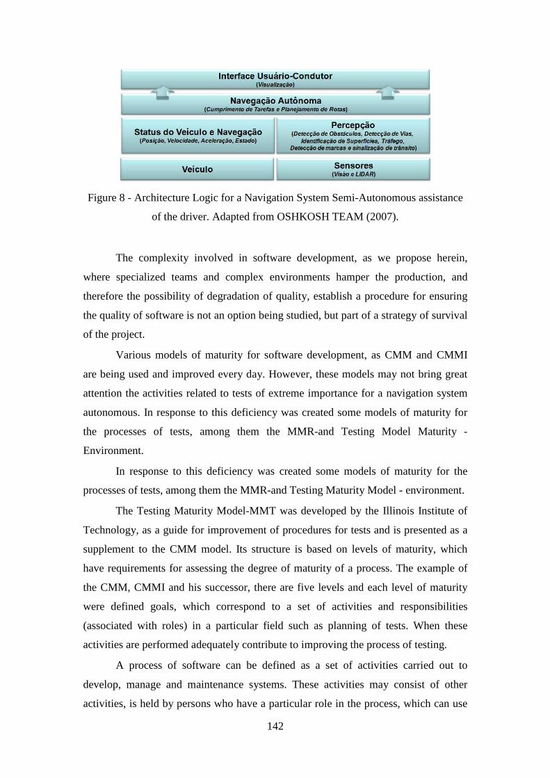
142
Figure 8 - Architecture Logic for a Navigation System Semi-Autonomous assistance
of the driver. Adapted from OSHKOSH TEAM (2007).
The complexity involved in software development, as we propose herein,
where specialized teams and complex environments hamper the production, and
therefore the possibility of degradation of quality, establish a procedure for ensuring
the quality of software is not an option being studied, but part of a strategy of survival
of the project.
Various models of maturity for software development, as CMM and CMMI
are being used and improved every day. However, these models may not bring great
attention the activities related to tests of extreme importance for a navigation system
autonomous. In response to this deficiency was created some models of maturity for
the processes of tests, among them the MMR-and Testing Model Maturity -
Environment.
In response to this deficiency was created some models of maturity for the
processes of tests, among them the MMR-and Testing Maturity Model - environment.
The Testing Maturity Model-MMT was developed by the Illinois Institute of
Technology, as a guide for improvement of procedures for tests and is presented as a
supplement to the CMM model. Its structure is based on levels of maturity, which
have requirements for assessing the degree of maturity of a process. The example of
the CMM, CMMI and his successor, there are five levels and each level of maturity
were defined goals, which correspond to a set of activities and responsibilities
(associated with roles) in a particular field such as planning of tests. When these
activities are performed adequately contribute to improving the process of testing.
A process of software can be defined as a set of activities carried out to
develop, manage and maintenance systems. These activities may consist of other
activities, is held by persons who have a particular role in the process, which can use
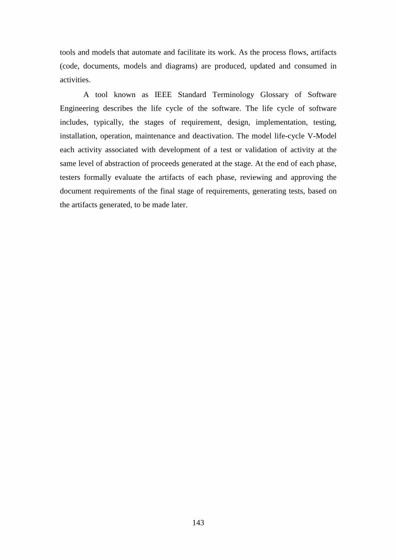
143
tools and models that automate and facilitate its work. As the process flows, artifacts
(code, documents, models and diagrams) are produced, updated and consumed in
activities.
A tool known as IEEE Standard Terminology Glossary of Software
Engineering describes the life cycle of the software. The life cycle of software
includes, typically, the stages of requirement, design, implementation, testing,
installation, operation, maintenance and deactivation. The model life-cycle V-Model
each activity associated with development of a test or validation of activity at the
same level of abstraction of proceeds generated at the stage. At the end of each phase,
testers formally evaluate the artifacts of each phase, reviewing and approving the
document requirements of the final stage of requirements, generating tests, based on
the artifacts generated, to be made later.

144
Figure 9 - Macro diagram Logic of Architecture. Adapted from OSHKOSH TEAM
(2007).
In the V-Model the involvement of testers is given since the beginning of the
development enabling defects are discovered sooner than in traditional models. The
stages are presented in Figure 10.
In the last multi-conference held in the state of Texas-USA, IEEE 2008 Multi-
conference on Systems and Control (MSC) was presented a case study of the use of
the V-Model (or V-Shape - Software Development Validation) for development and
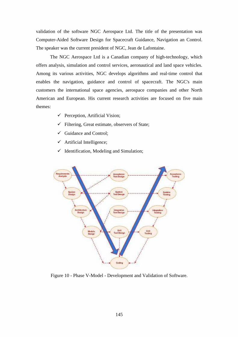
145
validation of the software NGC Aerospace Ltd. The title of the presentation was
Computer-Aided Software Design for Spacecraft Guidance, Navigation an Control.
The speaker was the current president of NGC, Jean de Lafontaine.
The NGC Aerospace Ltd is a Canadian company of high-technology, which
offers analysis, simulation and control services, aeronautical and land space vehicles.
Among its various activities, NGC develops algorithms and real-time control that
enables the navigation, guidance and control of spacecraft. The NGC's main
customers the international space agencies, aerospace companies and other North
American and European. His current research activities are focused on five main
themes:
� Perception, Artificial Vision;
� Filtering, Great estimate, observers of State;
� Guidance and Control;
� Artificial Intelligence;
� Identification, Modeling and Simulation;
Figure 10 - Phase V-Model - Development and Validation of Software.
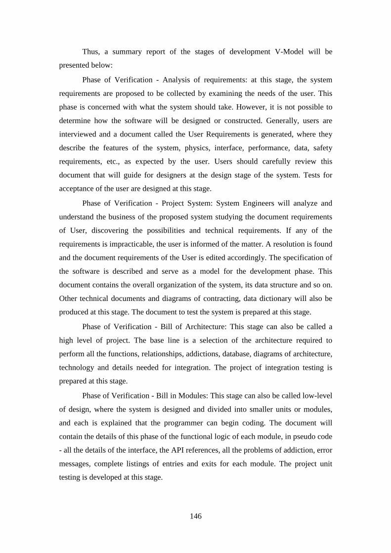
146
Thus, a summary report of the stages of development V-Model will be
presented below:
Phase of Verification - Analysis of requirements: at this stage, the system
requirements are proposed to be collected by examining the needs of the user. This
phase is concerned with what the system should take. However, it is not possible to
determine how the software will be designed or constructed. Generally, users are
interviewed and a document called the User Requirements is generated, where they
describe the features of the system, physics, interface, performance, data, safety
requirements, etc., as expected by the user. Users should carefully review this
document that will guide for designers at the design stage of the system. Tests for
acceptance of the user are designed at this stage.
Phase of Verification - Project System: System Engineers will analyze and
understand the business of the proposed system studying the document requirements
of User, discovering the possibilities and technical requirements. If any of the
requirements is impracticable, the user is informed of the matter. A resolution is found
and the document requirements of the User is edited accordingly. The specification of
the software is described and serve as a model for the development phase. This
document contains the overall organization of the system, its data structure and so on.
Other technical documents and diagrams of contracting, data dictionary will also be
produced at this stage. The document to test the system is prepared at this stage.
Phase of Verification - Bill of Architecture: This stage can also be called a
high level of project. The base line is a selection of the architecture required to
perform all the functions, relationships, addictions, database, diagrams of architecture,
technology and details needed for integration. The project of integration testing is
prepared at this stage.
Phase of Verification - Bill in Modules: This stage can also be called low-level
of design, where the system is designed and divided into smaller units or modules,
and each is explained that the programmer can begin coding. The document will
contain the details of this phase of the functional logic of each module, in pseudo code
- all the details of the interface, the API references, all the problems of addiction, error
messages, complete listings of entries and exits for each module. The project unit
testing is developed at this stage.
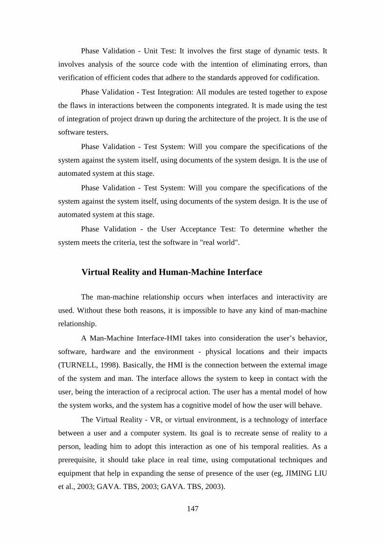
147
Phase Validation - Unit Test: It involves the first stage of dynamic tests. It
involves analysis of the source code with the intention of eliminating errors, than
verification of efficient codes that adhere to the standards approved for codification.
Phase Validation - Test Integration: All modules are tested together to expose
the flaws in interactions between the components integrated. It is made using the test
of integration of project drawn up during the architecture of the project. It is the use of
software testers.
Phase Validation - Test System: Will you compare the specifications of the
system against the system itself, using documents of the system design. It is the use of
automated system at this stage.
Phase Validation - Test System: Will you compare the specifications of the
system against the system itself, using documents of the system design. It is the use of
automated system at this stage.
Phase Validation - the User Acceptance Test: To determine whether the
system meets the criteria, test the software in "real world".
Virtual Reality and Human-Machine Interface
The man-machine relationship occurs when interfaces and interactivity are
used. Without these both reasons, it is impossible to have any kind of man-machine
relationship.
A Man-Machine Interface-HMI takes into consideration the user’s behavior,
software, hardware and the environment - physical locations and their impacts
(TURNELL, 1998). Basically, the HMI is the connection between the external image
of the system and man. The interface allows the system to keep in contact with the
user, being the interaction of a reciprocal action. The user has a mental model of how
the system works, and the system has a cognitive model of how the user will behave.
The Virtual Reality - VR, or virtual environment, is a technology of interface
between a user and a computer system. Its goal is to recreate sense of reality to a
person, leading him to adopt this interaction as one of his temporal realities. As a
prerequisite, it should take place in real time, using computational techniques and
equipment that help in expanding the sense of presence of the user (eg, JIMING LIU
et al., 2003; GAVA. TBS, 2003; GAVA. TBS, 2003).
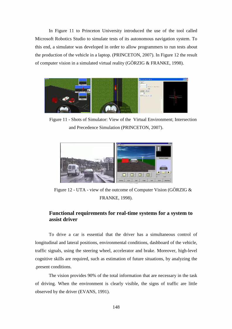
148
In Figure 11 to Princeton University introduced the use of the tool called
Microsoft Robotics Studio to simulate tests of its autonomous navigation system. To
this end, a simulator was developed in order to allow programmers to run tests about
the production of the vehicle in a laptop. (PRINCETON, 2007). In Figure 12 the result
of computer vision in a simulated virtual reality (GÖRZIG & FRANKE, 1998).
Figure 11 - Shots of Simulator: View of the Virtual Environment; Intersection
and Precedence Simulation (PRINCETON, 2007).
Figure 12 - UTA - view of the outcome of Computer Vision (GÖRZIG &
FRANKE, 1998).
Functional requirements for real-time systems for a system to assist driver
To drive a car is essential that the driver has a simultaneous control of
longitudinal and lateral positions, environmental conditions, dashboard of the vehicle,
traffic signals, using the steering wheel, accelerator and brake. Moreover, high-level
cognitive skills are required, such as estimation of future situations, by analyzing the
.present conditions.
The vision provides 90% of the total information that are necessary in the task
of driving. When the environment is clearly visible, the signs of traffic are little
observed by the driver (EVANS, 1991).
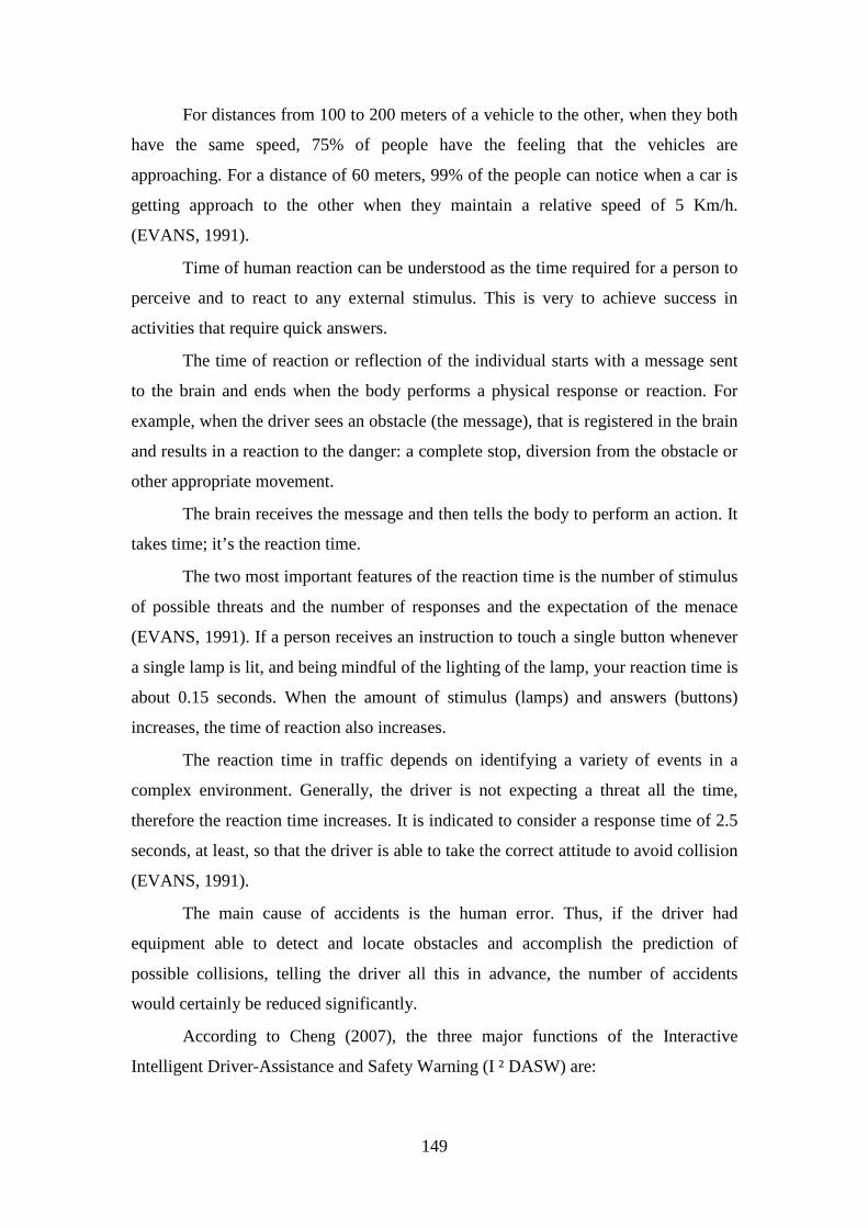
149
For distances from 100 to 200 meters of a vehicle to the other, when they both
have the same speed, 75% of people have the feeling that the vehicles are
approaching. For a distance of 60 meters, 99% of the people can notice when a car is
getting approach to the other when they maintain a relative speed of 5 Km/h.
(EVANS, 1991).
Time of human reaction can be understood as the time required for a person to
perceive and to react to any external stimulus. This is very to achieve success in
activities that require quick answers.
The time of reaction or reflection of the individual starts with a message sent
to the brain and ends when the body performs a physical response or reaction. For
example, when the driver sees an obstacle (the message), that is registered in the brain
and results in a reaction to the danger: a complete stop, diversion from the obstacle or
other appropriate movement.
The brain receives the message and then tells the body to perform an action. It
takes time; it’s the reaction time.
The two most important features of the reaction time is the number of stimulus
of possible threats and the number of responses and the expectation of the menace
(EVANS, 1991). If a person receives an instruction to touch a single button whenever
a single lamp is lit, and being mindful of the lighting of the lamp, your reaction time is
about 0.15 seconds. When the amount of stimulus (lamps) and answers (buttons)
increases, the time of reaction also increases.
The reaction time in traffic depends on identifying a variety of events in a
complex environment. Generally, the driver is not expecting a threat all the time,
therefore the reaction time increases. It is indicated to consider a response time of 2.5
seconds, at least, so that the driver is able to take the correct attitude to avoid collision
(EVANS, 1991).
The main cause of accidents is the human error. Thus, if the driver had
equipment able to detect and locate obstacles and accomplish the prediction of
possible collisions, telling the driver all this in advance, the number of accidents
would certainly be reduced significantly.
According to Cheng (2007), the three major functions of the Interactive
Intelligent Driver-Assistance and Safety Warning (I ² DASW) are:
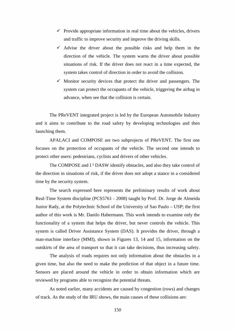
150
� Provide appropriate information in real time about the vehicles, drivers
and traffic to improve security and improve the driving skills.
� Advise the driver about the possible risks and help them in the
direction of the vehicle. The system warns the driver about possible
situations of risk. If the driver does not react in a time expected, the
system takes control of direction in order to avoid the collision.
� Monitor security devices that protect the driver and passengers. The
system can protect the occupants of the vehicle, triggering the airbag in
advance, when see that the collision is certain.
The PReVENT integrated project is led by the European Automobile Industry
and it aims to contribute to the road safety by developing technologies and then
launching them.
APALACI and COMPOSE are two subprojects of PReVENT. The first one
focuses on the protection of occupants of the vehicle. The second one intends to
protect other users: pedestrians, cyclists and drivers of other vehicles.
The COMPOSE and I ² DASW identify obstacles, and also they take control of
the direction in situations of risk, if the driver does not adopt a stance in a considered
time by the security system.
The search expressed here represents the preliminary results of work about
Real-Time System discipline (PCS5761 - 2008) taught by Prof. Dr. Jorge de Almeida
Junior Rady, at the Polytechnic School of the University of Sao Paulo – USP; the first
author of this work is Mr. Danilo Habermann. This work intends to examine only the
functionality of a system that helps the driver, but never controls the vehicle. This
system is called Driver Assistance System (DAS). It provides the driver, through a
man-machine interface (MMI), shown in Figures 13, 14 and 15, information on the
outskirts of the area of transport so that it can take decisions, thus increasing safety.
The analysis of roads requires not only information about the obstacles in a
given time, but also the need to make the prediction of that object in a future time.
Sensors are placed around the vehicle in order to obtain information which are
reviewed by programs able to recognize the potential threats.
As noted earlier, many accidents are caused by congestion (rows) and changes
of track. As the study of the IRU shows, the main causes of these collisions are:
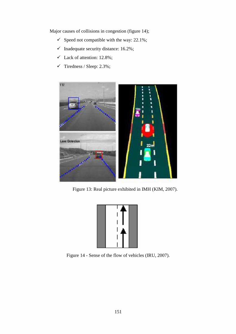
151
Major causes of collisions in congestion (figure 14);
� Speed not compatible with the way: 22.1%;
� Inadequate security distance: 16.2%;
� Lack of attention: 12.8%;
� Tiredness / Sleep: 2.3%;
Figure 13: Real picture exhibited in IMH (KIM, 2007).
Figure 14 - Sense of the flow of vehicles (IRU, 2007).
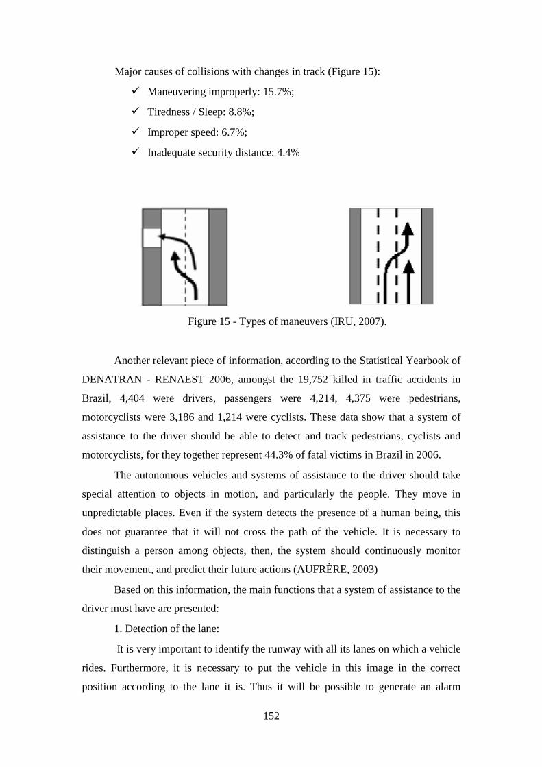
152
Major causes of collisions with changes in track (Figure 15):
� Maneuvering improperly: 15.7%;
� Tiredness / Sleep: 8.8%;
� Improper speed: 6.7%;
� Inadequate security distance: 4.4%
Figure 15 - Types of maneuvers (IRU, 2007).
Another relevant piece of information, according to the Statistical Yearbook of
DENATRAN - RENAEST 2006, amongst the 19,752 killed in traffic accidents in
Brazil, 4,404 were drivers, passengers were 4,214, 4,375 were pedestrians,
motorcyclists were 3,186 and 1,214 were cyclists. These data show that a system of
assistance to the driver should be able to detect and track pedestrians, cyclists and
motorcyclists, for they together represent 44.3% of fatal victims in Brazil in 2006.
The autonomous vehicles and systems of assistance to the driver should take
special attention to objects in motion, and particularly the people. They move in
unpredictable places. Even if the system detects the presence of a human being, this
does not guarantee that it will not cross the path of the vehicle. It is necessary to
distinguish a person among objects, then, the system should continuously monitor
their movement, and predict their future actions (AUFRÈRE, 2003)
Based on this information, the main functions that a system of assistance to the
driver must have are presented:
1. Detection of the lane:
It is very important to identify the runway with all its lanes on which a vehicle
rides. Furthermore, it is necessary to put the vehicle in this image in the correct
position according to the lane it is. Thus it will be possible to generate an alarm
153
whenever the vehicle begins to invade the other lanes or starts to leave the runway. To
identify the runway at the time of departure is necessary to identify the position and
direction of the limits of the painted lines. There are two ways of doing this; one of
them is to insert magnetic markers on lanes. However, there is a large cost involved in
this operation. The most usual way is to paint the lateral limits of the lane and then to
use computer vision to identify the place to ridden. When the image of a highway is
taken, it´s possible to notice that lane’s boundaries are more intensive than the paved
area, facilitating the identification (CHENG, 2007).
2. Detection and Tracking of vehicles:
All vehicles that are on the outskirts of the other one that has the SAC must be
detected and tracked. It is very important to determine the relative speeds of other
vehicles and to estimate the risks of occurring a collision. In general, sensors like
LIDAR, RADAR or SONAR measure the distance and direction to the obstacle, and
cameras help to identify the kind of the obstacle. Algorithms aim to identify some
specific patterns in the image as form and symmetry.
3. Detection and tracking of pedestrians:
According to Cheng (2007), infrared sensors are crucial to achieving an
accurate detection of people. The tracking of people is one of the most difficult tasks
to be performed due to the unpredictable behavior of them.
4. Detection of fixed objects:
It is important to find the other obstacles that make the streets and highways,
as slabs of traffic, barriers and trees. In general, RADAR sensors are used combined
with the video cameras.
5. Recognition of traffic signs:
As shown above, the incompatible speed to a certain lane causes many
accidents. Thus, it is necessary to identify the signs that indicate the maximum speed
allowed. Moreover, it is important to identify other signs as "STOP" and traffic lights
to prevent distracted drivers from passing through crossings in not allowed moments.
6. Prediction and warning of collisions:
When the location of mobile and fixed objects inserted into the virtual image
of the runway, the relative speed and direction and acceleration of the vehicle are
known, with the SAC, you can calculate the time of collision of each object. They

154
Two types of warning can be configured: warning notices and warnings of
emergency, depending on the degree of risk.
Currently, we have an increasing amount of applications that have defined
behaviors according to time restrictions. Some examples of these applications are in
control of industrial plants, rail or air traffic. Systems that have the characteristic of
being subjected to time restrictions, are commonly identified as Real-Time Systems.
A system of real time - SRT must satisfy restrictions of time to respond under
the risk of failure, causing serious accidents (LAPLANT, 2004).
A system for assisting the driver may be seen as a system of real time, as
wrong or outdated information in time may not meet the needs of the driver and cause
an accident. For example, suppose that the driver is traveling on long straight stretch
of a highway and for being inattentive not realize that his vehicle is approaching so
dangerous a vehicle in front, the SAC is not able to calculate the correct information
and not see the danger, or, if unable to process in sufficient time so that the driver can
reduce the speed or braking the vehicle, an accident occurs. It may bring serious
damage to the driver to other people.
The design and implementation of Real-Time Systems require attention to
several topics:
� Selection of Hardware and Software.
� Specification and design of STR and the correct representation of the
behavior of the system over time.
� Measure and predict the response time and try to reduce it.
The figure 16 brings the steps of a project of STR. You can see that the first
module is the analysis of the technical requirements of the system. This work aims,
from this point on, to determine the requirements for an SAC.
The requirements engineering focuses on the goals, functions and limitations
of the systems and with the representation of these aspects on a form capable of
modeling and analyzing the project. The goal is to create a complete specification of
requirements, correct to developers and customers. In real time systems, this task is
very complicated because of the need to make the requirements in time (LAPLANT,
2004).
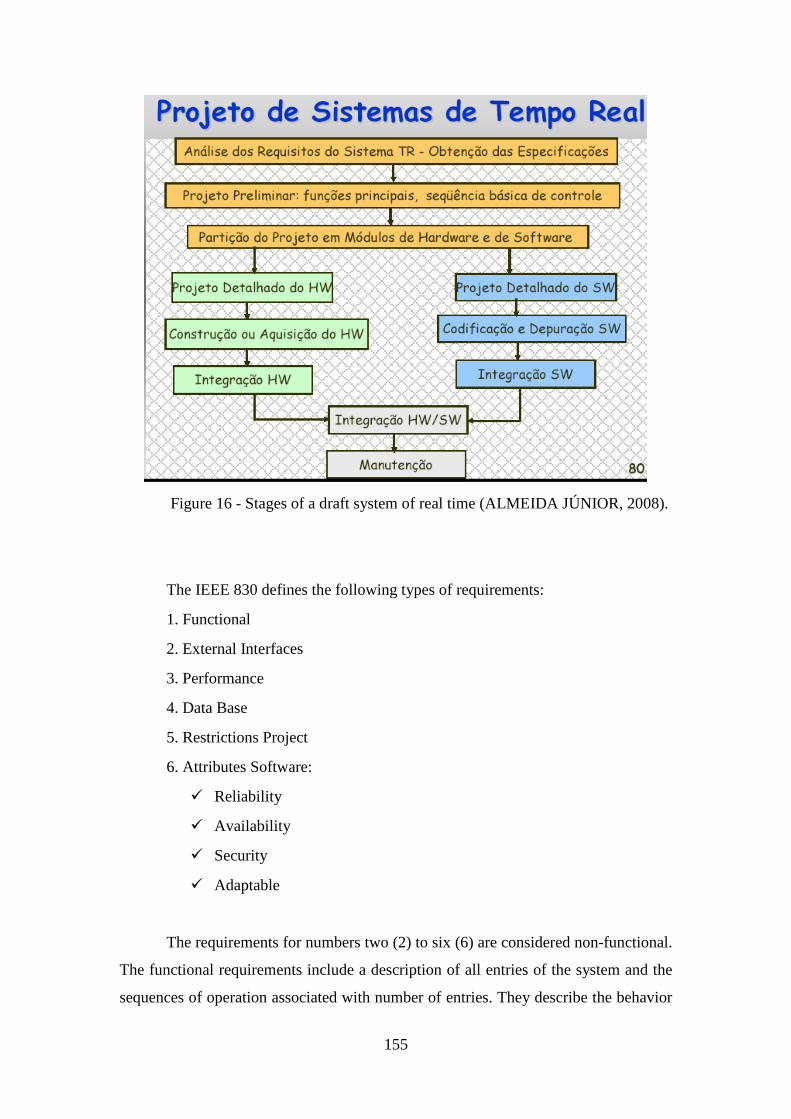
155
Figure 16 - Stages of a draft system of real time (ALMEIDA JÚNIOR, 2008).
The IEEE 830 defines the following types of requirements:
1. Functional
2. External Interfaces
3. Performance
4. Data Base
5. Restrictions Project
6. Attributes Software:
� Reliability
� Availability
� Security
� Adaptable
The requirements for numbers two (2) to six (6) are considered non-functional.
The functional requirements include a description of all entries of the system and the
sequences of operation associated with number of entries. They describe the behavior
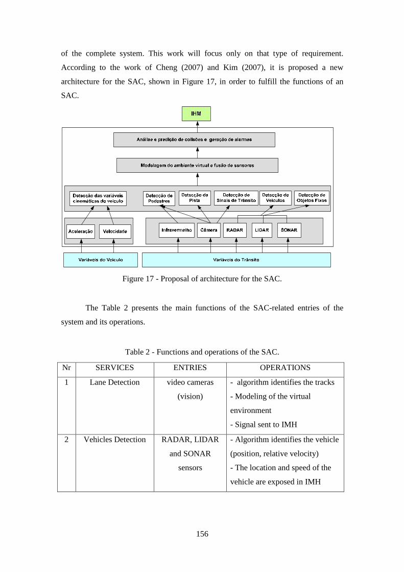
156
of the complete system. This work will focus only on that type of requirement.
According to the work of Cheng (2007) and Kim (2007), it is proposed a new
architecture for the SAC, shown in Figure 17, in order to fulfill the functions of an
SAC.
Figure 17 - Proposal of architecture for the SAC.
The Table 2 presents the main functions of the SAC-related entries of the
system and its operations.
Table 2 - Functions and operations of the SAC.
Nr SERVICES ENTRIES OPERATIONS
1 Lane Detection video cameras
(vision)
- algorithm identifies the tracks
- Modeling of the virtual
environment
- Signal sent to IMH
2 Vehicles Detection RADAR, LIDAR
and SONAR
sensors
- Algorithm identifies the vehicle
(position, relative velocity)
- The location and speed of the
vehicle are exposed in IMH
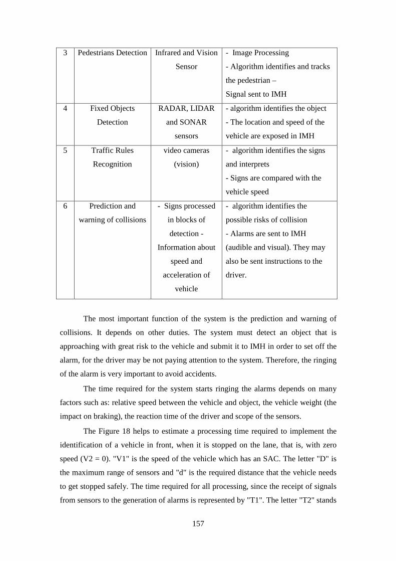
157
3 Pedestrians Detection Infrared and Vision
Sensor
- Image Processing
- Algorithm identifies and tracks
the pedestrian –
Signal sent to IMH
4 Fixed Objects
Detection
RADAR, LIDAR
and SONAR
sensors
- algorithm identifies the object
- The location and speed of the
vehicle are exposed in IMH
5 Traffic Rules
Recognition
video cameras
(vision)
- algorithm identifies the signs
and interprets
- Signs are compared with the
vehicle speed
6 Prediction and
warning of collisions
- Signs processed
in blocks of
detection -
Information about
speed and
acceleration of
vehicle
- algorithm identifies the
possible risks of collision
- Alarms are sent to IMH
(audible and visual). They may
also be sent instructions to the
driver.
The most important function of the system is the prediction and warning of
collisions. It depends on other duties. The system must detect an object that is
approaching with great risk to the vehicle and submit it to IMH in order to set off the
alarm, for the driver may be not paying attention to the system. Therefore, the ringing
of the alarm is very important to avoid accidents.
The time required for the system starts ringing the alarms depends on many
factors such as: relative speed between the vehicle and object, the vehicle weight (the
impact on braking), the reaction time of the driver and scope of the sensors.
The Figure 18 helps to estimate a processing time required to implement the
identification of a vehicle in front, when it is stopped on the lane, that is, with zero
speed (V2 = 0). "V1" is the speed of the vehicle which has an SAC. The letter "D" is
the maximum range of sensors and "d" is the required distance that the vehicle needs
to get stopped safely. The time required for all processing, since the receipt of signals
from sensors to the generation of alarms is represented by "T1". The letter "T2" stands
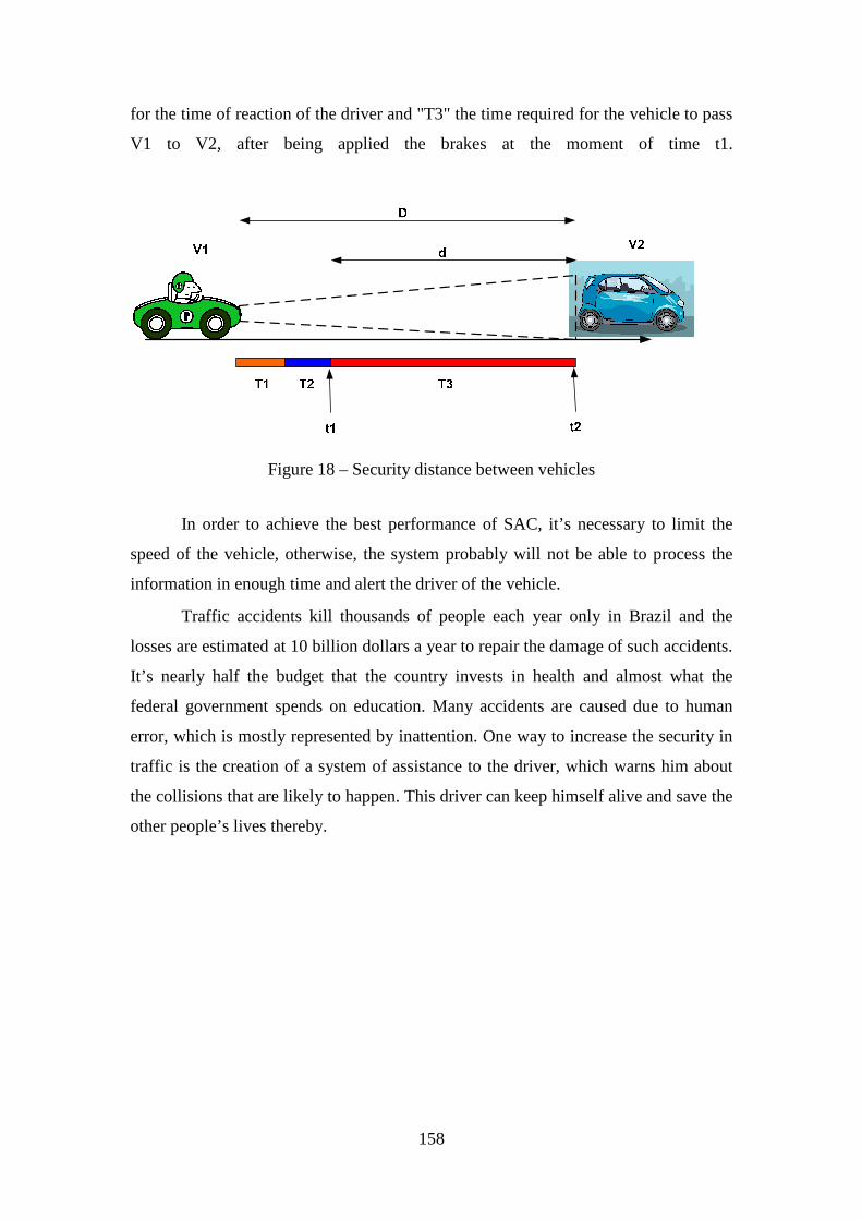
158
for the time of reaction of the driver and "T3" the time required for the vehicle to pass
V1 to V2, after being applied the brakes at the moment of time t1.
Figure 18 – Security distance between vehicles
In order to achieve the best performance of SAC, it’s necessary to limit the
speed of the vehicle, otherwise, the system probably will not be able to process the
information in enough time and alert the driver of the vehicle.
Traffic accidents kill thousands of people each year only in Brazil and the
losses are estimated at 10 billion dollars a year to repair the damage of such accidents.
It’s nearly half the budget that the country invests in health and almost what the
federal government spends on education. Many accidents are caused due to human
error, which is mostly represented by inattention. One way to increase the security in
traffic is the creation of a system of assistance to the driver, which warns him about
the collisions that are likely to happen. This driver can keep himself alive and save the
other people’s lives thereby.
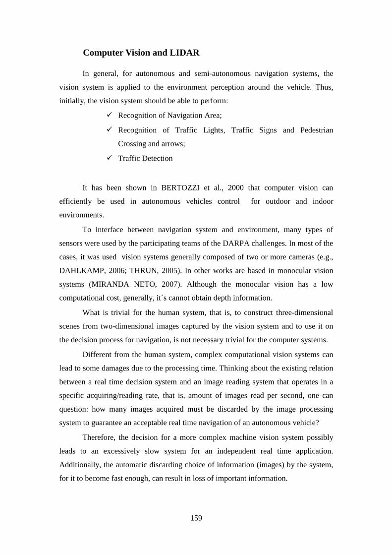
159
Computer Vision and LIDAR
In general, for autonomous and semi-autonomous navigation systems, the
vision system is applied to the environment perception around the vehicle. Thus,
initially, the vision system should be able to perform:
� Recognition of Navigation Area;
� Recognition of Traffic Lights, Traffic Signs and Pedestrian
Crossing and arrows;
� Traffic Detection
It has been shown in BERTOZZI et al., 2000 that computer vision can
efficiently be used in autonomous vehicles control for outdoor and indoor
environments.
To interface between navigation system and environment, many types of
sensors were used by the participating teams of the DARPA challenges. In most of the
cases, it was used vision systems generally composed of two or more cameras (e.g.,
DAHLKAMP, 2006; THRUN, 2005). In other works are based in monocular vision
systems (MIRANDA NETO, 2007). Although the monocular vision has a low
computational cost, generally, it´s cannot obtain depth information.
What is trivial for the human system, that is, to construct three-dimensional
scenes from two-dimensional images captured by the vision system and to use it on
the decision process for navigation, is not necessary trivial for the computer systems.
Different from the human system, complex computational vision systems can
lead to some damages due to the processing time. Thinking about the existing relation
between a real time decision system and an image reading system that operates in a
specific acquiring/reading rate, that is, amount of images read per second, one can
question: how many images acquired must be discarded by the image processing
system to guarantee an acceptable real time navigation of an autonomous vehicle?
Therefore, the decision for a more complex machine vision system possibly
leads to an excessively slow system for an independent real time application.
Additionally, the automatic discarding choice of information (images) by the system,
for it to become fast enough, can result in loss of important information.
160
Although the system could maintain a database of acquired images and
submits it, for example, to a neural network for decision, the great number of
information not necessarily would lead to better decisions and also could harm the
performance of the system, overloading it.
Due to the general applicability of it, the problem of navigation of mobile
robots is dealt with using more complex techniques. The most common ones are
based on the processing of two or more images, such as the analysis of the optical
flow field and the processing of non-monocular images.
In the first case more than one image are acquired by the same sensor in
different time instants, while in the second one multiple cameras acquire images
simultaneously, but from different points of view. Besides their intrinsic higher
computational complexity caused by a significant increment in the amount of data to
be processed, these techniques must also be robust enough to tolerate noise caused by
vehicle movements and drifts in the calibration of the multiple cameras’ setup.
The optical flow-based technique requires the analysis of a sequence of two or
more images: a two-dimensional vector is computed in the image domain, encoding
the horizontal and vertical components of the velocity of each pixel (HORN &
SCHUNCK, 1981). The result can be used to compute ego-motion, which in some
systems are directly extracted from odometry; obstacles can be detected by analyzing
the difference between the expected and real velocity fields.
Although extremely complex and highly demanding, thanks to the great deal
of information it can deliver, machine vision is a powerful means for sensing the
environment and has been widely employed to deal with a large number of tasks in
the automotive field. But complex computer vision systems may perform
unsatisfactorily due to its processing time. Thinking about the existing relation
between a real time decision system and an image reading system that operates in an
specific acquiring/reading rate. Therefore, the decision for a more complex machine
vision system possibly leads to an excessively slow system.
Although the system could maintain a database of acquired images and submit
it, for example, to a neural network for decision, the great amount of information
would not necessarily lead to better decisions and could also harm the performance of
the system, overloading it. However, in figure 19, FRANKE et al. (2000) presented
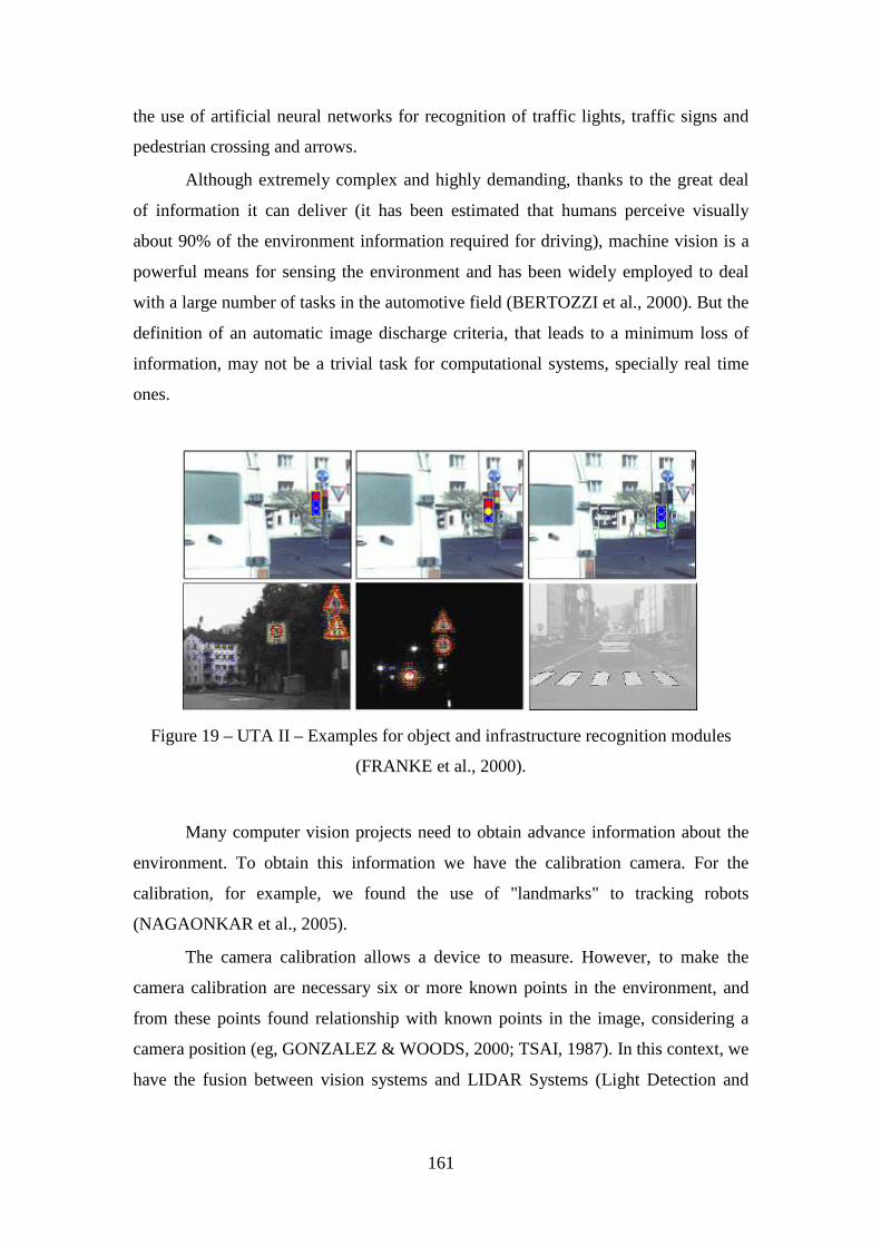
161
the use of artificial neural networks for recognition of traffic lights, traffic signs and
pedestrian crossing and arrows.
Although extremely complex and highly demanding, thanks to the great deal
of information it can deliver (it has been estimated that humans perceive visually
about 90% of the environment information required for driving), machine vision is a
powerful means for sensing the environment and has been widely employed to deal
with a large number of tasks in the automotive field (BERTOZZI et al., 2000). But the
definition of an automatic image discharge criteria, that leads to a minimum loss of
information, may not be a trivial task for computational systems, specially real time
ones.
Figure 19 – UTA II – Examples for object and infrastructure recognition modules
(FRANKE et al., 2000).
Many computer vision projects need to obtain advance information about the
environment. To obtain this information we have the calibration camera. For the
calibration, for example, we found the use of "landmarks" to tracking robots
(NAGAONKAR et al., 2005).
The camera calibration allows a device to measure. However, to make the
camera calibration are necessary six or more known points in the environment, and
from these points found relationship with known points in the image, considering a
camera position (eg, GONZALEZ & WOODS, 2000; TSAI, 1987). In this context, we
have the fusion between vision systems and LIDAR Systems (Light Detection and
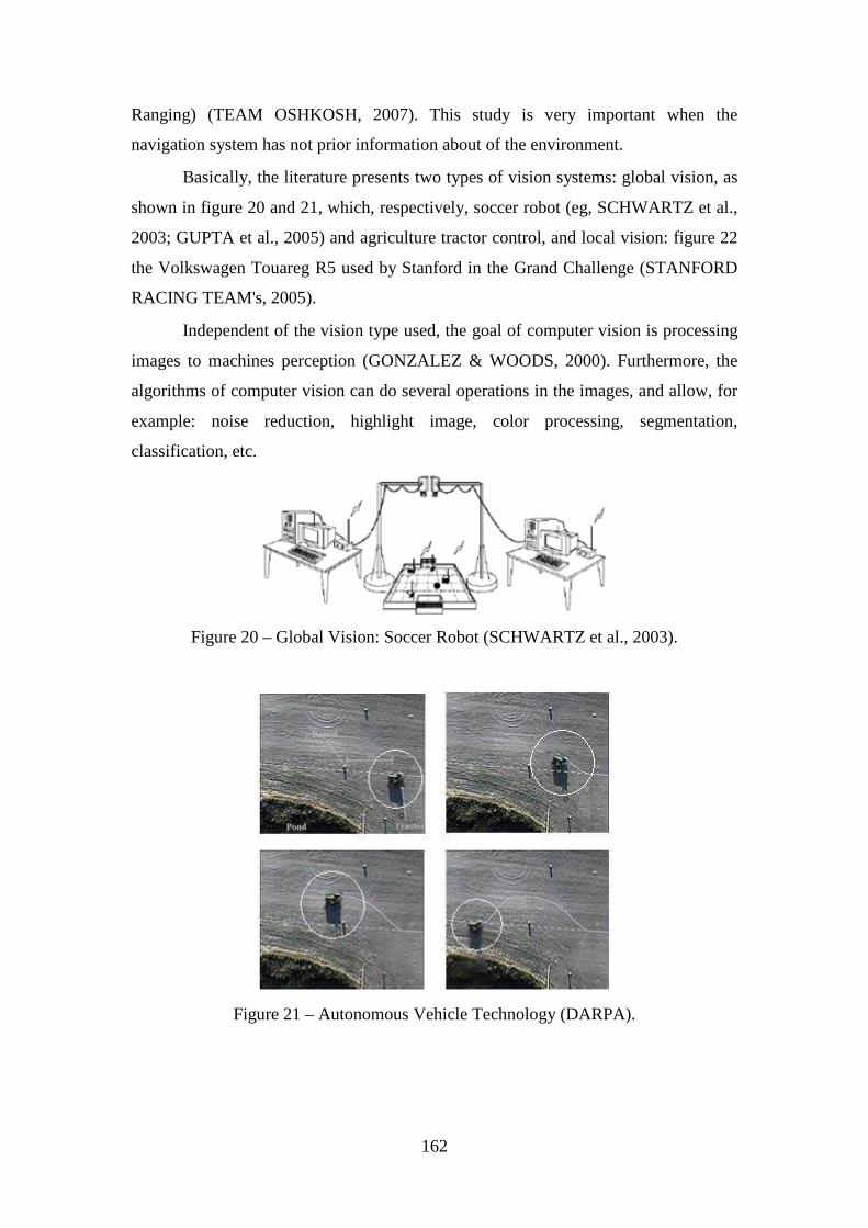
162
Ranging) (TEAM OSHKOSH, 2007). This study is very important when the
navigation system has not prior information about of the environment.
Basically, the literature presents two types of vision systems: global vision, as
shown in figure 20 and 21, which, respectively, soccer robot (eg, SCHWARTZ et al.,
2003; GUPTA et al., 2005) and agriculture tractor control, and local vision: figure 22
the Volkswagen Touareg R5 used by Stanford in the Grand Challenge (STANFORD
RACING TEAM's, 2005).
Independent of the vision type used, the goal of computer vision is processing
images to machines perception (GONZALEZ & WOODS, 2000). Furthermore, the
algorithms of computer vision can do several operations in the images, and allow, for
example: noise reduction, highlight image, color processing, segmentation,
classification, etc.
Figure 20 – Global Vision: Soccer Robot (SCHWARTZ et al., 2003).
Figure 21 – Autonomous Vehicle Technology (DARPA).
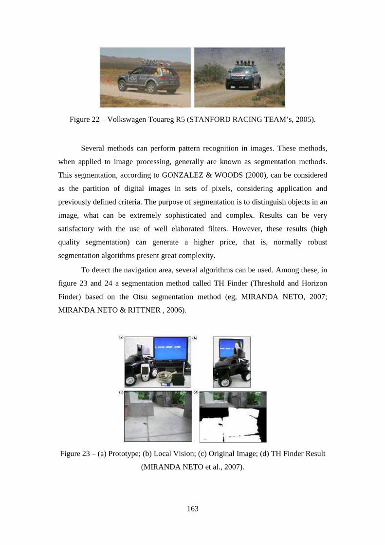
163
Figure 22 – Volkswagen Touareg R5 (STANFORD RACING TEAM’s, 2005).
Several methods can perform pattern recognition in images. These methods,
when applied to image processing, generally are known as segmentation methods.
This segmentation, according to GONZALEZ & WOODS (2000), can be considered
as the partition of digital images in sets of pixels, considering application and
previously defined criteria. The purpose of segmentation is to distinguish objects in an
image, what can be extremely sophisticated and complex. Results can be very
satisfactory with the use of well elaborated filters. However, these results (high
quality segmentation) can generate a higher price, that is, normally robust
segmentation algorithms present great complexity.
To detect the navigation area, several algorithms can be used. Among these, in
figure 23 and 24 a segmentation method called TH Finder (Threshold and Horizon
Finder) based on the Otsu segmentation method (eg, MIRANDA NETO, 2007;
MIRANDA NETO & RITTNER , 2006).
Figure 23 – (a) Prototype; (b) Local Vision; (c) Original Image; (d) TH Finder Result
(MIRANDA NETO et al., 2007).
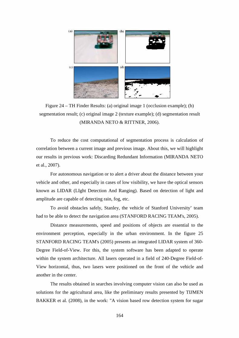
164
Figure 24 – TH Finder Results: (a) original image 1 (occlusion example); (b)
segmentation result; (c) original image 2 (texture example); (d) segmentation result
(MIRANDA NETO & RITTNER, 2006).
To reduce the cost computational of segmentation process is calculation of
correlation between a current image and previous image. About this, we will highlight
our results in previous work: Discarding Redundant Information (MIRANDA NETO
et al., 2007).
For autonomous navigation or to alert a driver about the distance between your
vehicle and other, and especially in cases of low visibility, we have the optical sensors
known as LIDAR (LIght Detection And Ranging). Based on detection of light and
amplitude are capable of detecting rain, fog, etc.
To avoid obstacles safely, Stanley, the vehicle of Stanford University’ team
had to be able to detect the navigation area (STANFORD RACING TEAM's, 2005).
Distance measurements, speed and positions of objects are essential to the
environment perception, especially in the urban environment. In the figure 25
STANFORD RACING TEAM's (2005) presents an integrated LIDAR system of 360-
Degree Field-of-View. For this, the system software has been adapted to operate
within the system architecture. All lasers operated in a field of 240-Degree Field-of-
View horizontal, thus, two lasers were positioned on the front of the vehicle and
another in the center.
The results obtained in searches involving computer vision can also be used as
solutions for the agricultural area, like the preliminary results presented by TIJMEN
BAKKER et al. (2008), in the work: "A vision based row detection system for sugar
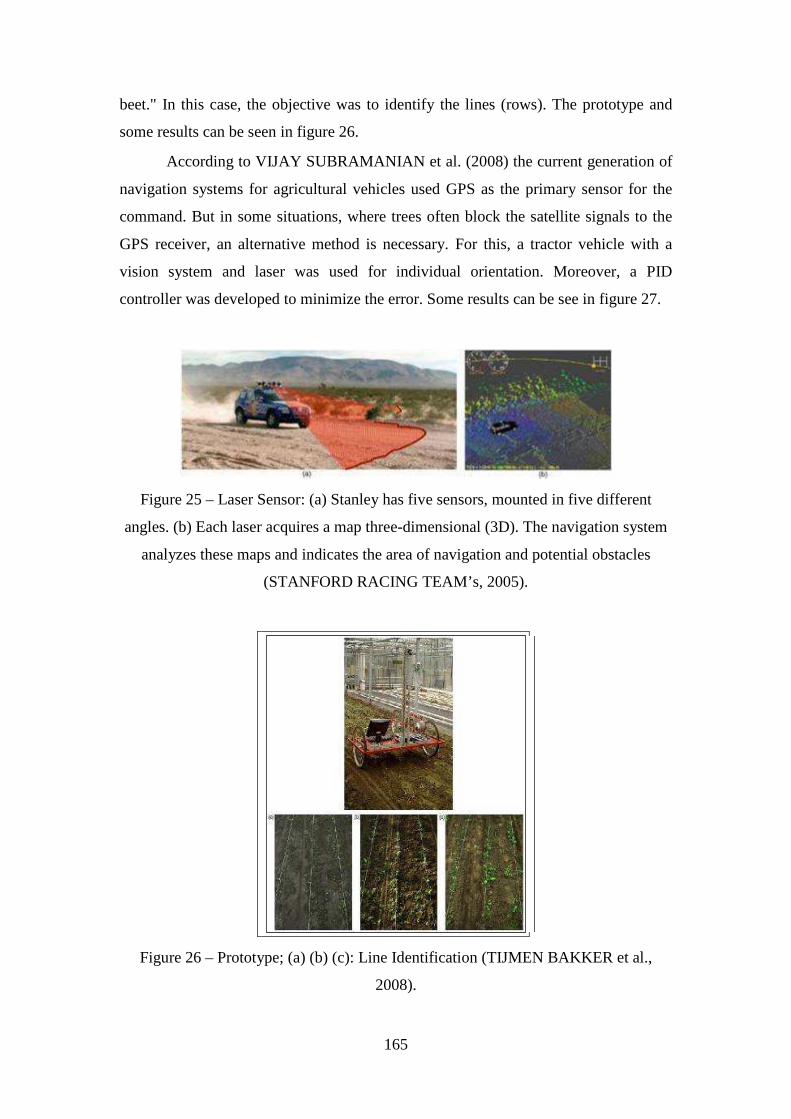
165
beet." In this case, the objective was to identify the lines (rows). The prototype and
some results can be seen in figure 26.
According to VIJAY SUBRAMANIAN et al. (2008) the current generation of
navigation systems for agricultural vehicles used GPS as the primary sensor for the
command. But in some situations, where trees often block the satellite signals to the
GPS receiver, an alternative method is necessary. For this, a tractor vehicle with a
vision system and laser was used for individual orientation. Moreover, a PID
controller was developed to minimize the error. Some results can be see in figure 27.
Figure 25 – Laser Sensor: (a) Stanley has five sensors, mounted in five different
angles. (b) Each laser acquires a map three-dimensional (3D). The navigation system
analyzes these maps and indicates the area of navigation and potential obstacles
(STANFORD RACING TEAM’s, 2005).
Figure 26 – Prototype; (a) (b) (c): Line Identification (TIJMEN BAKKER et al.,
2008).
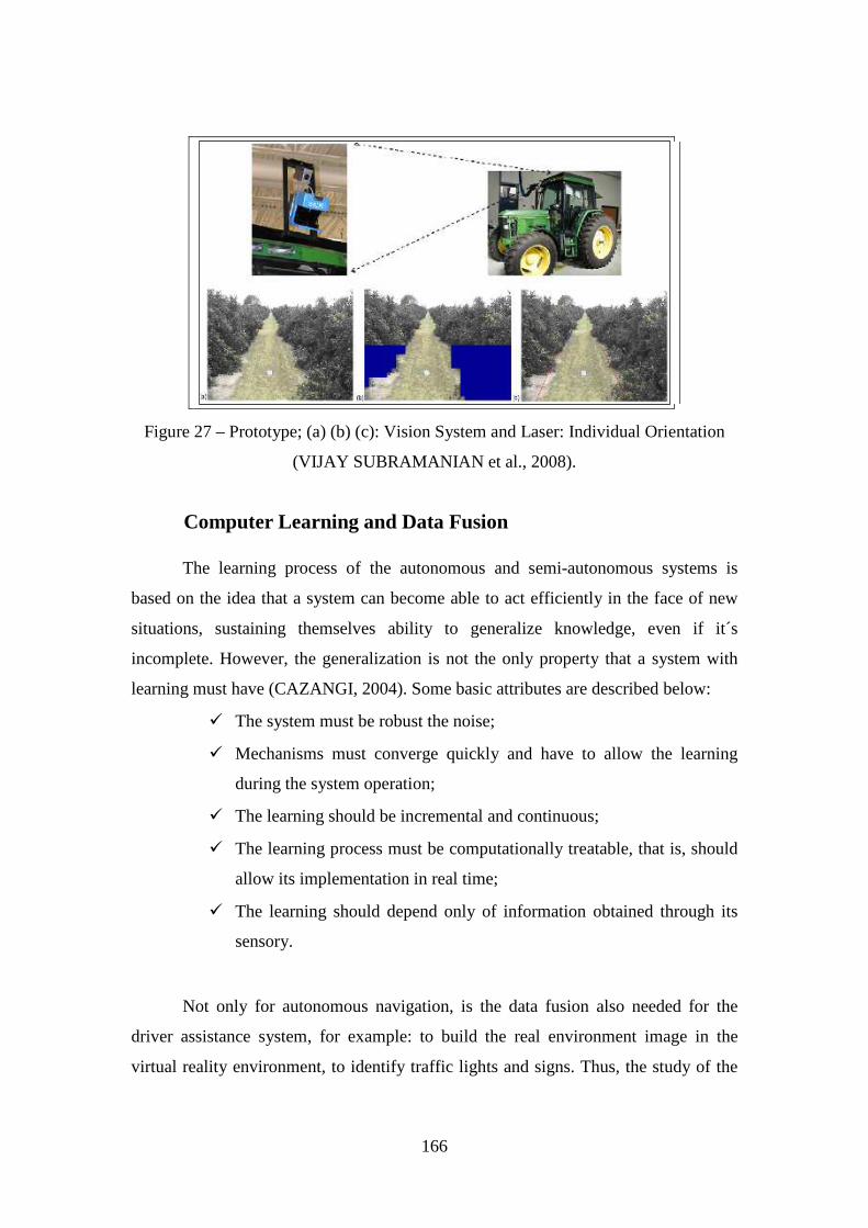
166
Figure 27 – Prototype; (a) (b) (c): Vision System and Laser: Individual Orientation
(VIJAY SUBRAMANIAN et al., 2008).
Computer Learning and Data Fusion
The learning process of the autonomous and semi-autonomous systems is
based on the idea that a system can become able to act efficiently in the face of new
situations, sustaining themselves ability to generalize knowledge, even if it´s
incomplete. However, the generalization is not the only property that a system with
learning must have (CAZANGI, 2004). Some basic attributes are described below:
� The system must be robust the noise;
� Mechanisms must converge quickly and have to allow the learning
during the system operation;
� The learning should be incremental and continuous;
� The learning process must be computationally treatable, that is, should
allow its implementation in real time;
� The learning should depend only of information obtained through its
sensory.
Not only for autonomous navigation, is the data fusion also needed for the
driver assistance system, for example: to build the real environment image in the
virtual reality environment, to identify traffic lights and signs. Thus, the study of the
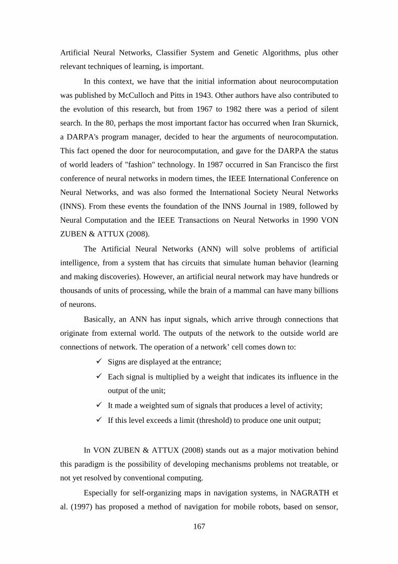
167
Artificial Neural Networks, Classifier System and Genetic Algorithms, plus other
relevant techniques of learning, is important.
In this context, we have that the initial information about neurocomputation
was published by McCulloch and Pitts in 1943. Other authors have also contributed to
the evolution of this research, but from 1967 to 1982 there was a period of silent
search. In the 80, perhaps the most important factor has occurred when Iran Skurnick,
a DARPA's program manager, decided to hear the arguments of neurocomputation.
This fact opened the door for neurocomputation, and gave for the DARPA the status
of world leaders of "fashion" technology. In 1987 occurred in San Francisco the first
conference of neural networks in modern times, the IEEE International Conference on
Neural Networks, and was also formed the International Society Neural Networks
(INNS). From these events the foundation of the INNS Journal in 1989, followed by
Neural Computation and the IEEE Transactions on Neural Networks in 1990 VON
ZUBEN & ATTUX (2008).
The Artificial Neural Networks (ANN) will solve problems of artificial
intelligence, from a system that has circuits that simulate human behavior (learning
and making discoveries). However, an artificial neural network may have hundreds or
thousands of units of processing, while the brain of a mammal can have many billions
of neurons.
Basically, an ANN has input signals, which arrive through connections that
originate from external world. The outputs of the network to the outside world are
connections of network. The operation of a network’ cell comes down to:
� Signs are displayed at the entrance;
� Each signal is multiplied by a weight that indicates its influence in the
output of the unit;
� It made a weighted sum of signals that produces a level of activity;
� If this level exceeds a limit (threshold) to produce one unit output;
In VON ZUBEN & ATTUX (2008) stands out as a major motivation behind
this paradigm is the possibility of developing mechanisms problems not treatable, or
not yet resolved by conventional computing.
Especially for self-organizing maps in navigation systems, in NAGRATH et
al. (1997) has proposed a method of navigation for mobile robots, based on sensor,
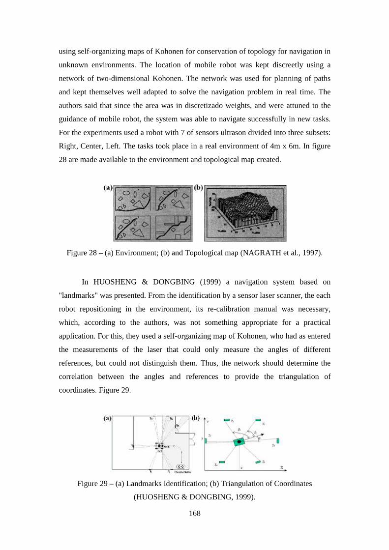
168
using self-organizing maps of Kohonen for conservation of topology for navigation in
unknown environments. The location of mobile robot was kept discreetly using a
network of two-dimensional Kohonen. The network was used for planning of paths
and kept themselves well adapted to solve the navigation problem in real time. The
authors said that since the area was in discretizado weights, and were attuned to the
guidance of mobile robot, the system was able to navigate successfully in new tasks.
For the experiments used a robot with 7 of sensors ultrason divided into three subsets:
Right, Center, Left. The tasks took place in a real environment of 4m x 6m. In figure
28 are made available to the environment and topological map created.
Figure 28 – (a) Environment; (b) and Topological map (NAGRATH et al., 1997).
In HUOSHENG & DONGBING (1999) a navigation system based on
"landmarks" was presented. From the identification by a sensor laser scanner, the each
robot repositioning in the environment, its re-calibration manual was necessary,
which, according to the authors, was not something appropriate for a practical
application. For this, they used a self-organizing map of Kohonen, who had as entered
the measurements of the laser that could only measure the angles of different
references, but could not distinguish them. Thus, the network should determine the
correlation between the angles and references to provide the triangulation of
coordinates. Figure 29.
Figure 29 – (a) Landmarks Identification; (b) Triangulation of Coordinates
(HUOSHENG & DONGBING, 1999).
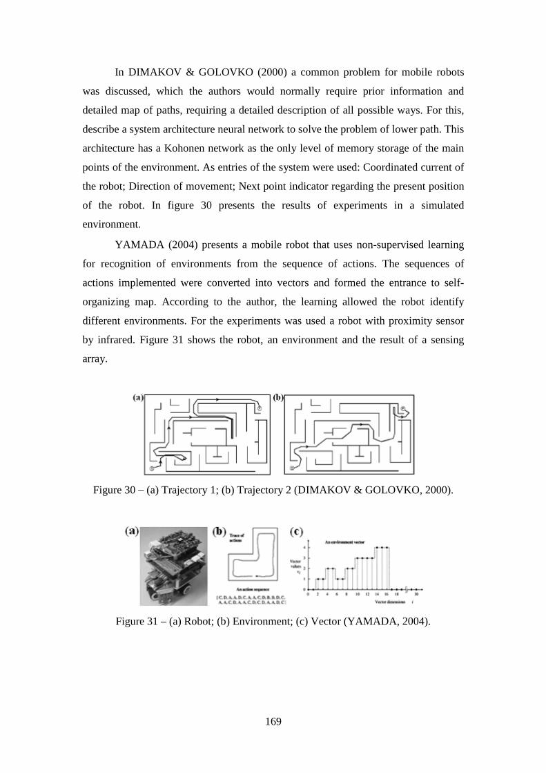
169
In DIMAKOV & GOLOVKO (2000) a common problem for mobile robots
was discussed, which the authors would normally require prior information and
detailed map of paths, requiring a detailed description of all possible ways. For this,
describe a system architecture neural network to solve the problem of lower path. This
architecture has a Kohonen network as the only level of memory storage of the main
points of the environment. As entries of the system were used: Coordinated current of
the robot; Direction of movement; Next point indicator regarding the present position
of the robot. In figure 30 presents the results of experiments in a simulated
environment.
YAMADA (2004) presents a mobile robot that uses non-supervised learning
for recognition of environments from the sequence of actions. The sequences of
actions implemented were converted into vectors and formed the entrance to self-
organizing map. According to the author, the learning allowed the robot identify
different environments. For the experiments was used a robot with proximity sensor
by infrared. Figure 31 shows the robot, an environment and the result of a sensing
array.
Figure 30 – (a) Trajectory 1; (b) Trajectory 2 (DIMAKOV & GOLOVKO, 2000).
Figure 31 – (a) Robot; (b) Environment; (c) Vector (YAMADA, 2004).
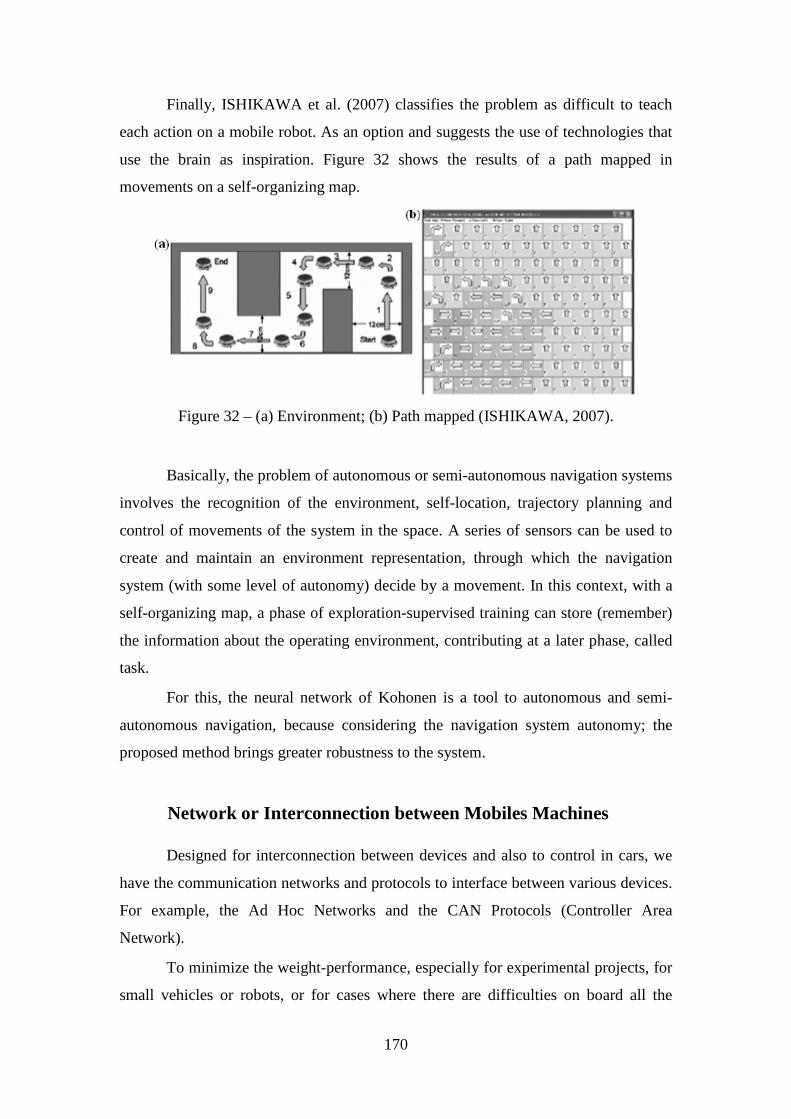
170
Finally, ISHIKAWA et al. (2007) classifies the problem as difficult to teach
each action on a mobile robot. As an option and suggests the use of technologies that
use the brain as inspiration. Figure 32 shows the results of a path mapped in
movements on a self-organizing map.
Figure 32 – (a) Environment; (b) Path mapped (ISHIKAWA, 2007).
Basically, the problem of autonomous or semi-autonomous navigation systems
involves the recognition of the environment, self-location, trajectory planning and
control of movements of the system in the space. A series of sensors can be used to
create and maintain an environment representation, through which the navigation
system (with some level of autonomy) decide by a movement. In this context, with a
self-organizing map, a phase of exploration-supervised training can store (remember)
the information about the operating environment, contributing at a later phase, called
task.
For this, the neural network of Kohonen is a tool to autonomous and semi-
autonomous navigation, because considering the navigation system autonomy; the
proposed method brings greater robustness to the system.
Network or Interconnection between Mobiles Machines
Designed for interconnection between devices and also to control in cars, we
have the communication networks and protocols to interface between various devices.
For example, the Ad Hoc Networks and the CAN Protocols (Controller Area
Network).
To minimize the weight-performance, especially for experimental projects, for
small vehicles or robots, or for cases where there are difficulties on board all the

171
hardware necessary, or by a strategy of action, various types of distributed system
architecture or client-server can be used. So some tasks, as storing and processing
information may be shared (between robots or vehicles) or assigned to a remote server
machine more powerful. This type of solution also allows the sharing of the database,
in addition to operations in cooperation. With this, information acquired from the
exploitation of environments determined by agent may be sharing by other
(MIRANDA NETO, 2007).
According TANENBAUM & VAN STEEN (2002) a distributed system based
on a collection of independent computers that are presented to the user as a single
system and allows the sharing of system resources: hardware, software and data.
Thus, including resources of computer networks, a system of parallel processing
joining several processing nodes, for example: individual computers not necessarily
homogeneous that processes a great computational cost run in the node more
available, or even subdivided by various nodes. Thus, any one task can be divided into
several subtasks running in parallel. Thus, the distributed computing is to add the
computational power of several computers or in different centers of the same
computer.
Currently processors use more of a core processing. Investing in parallel
architectures, the use of programming "multi-thread" is to put more threads within a
single process. So, in parallel programming the development of programs depends on
the type of architecture (OLIVEIRA et al., 2004). Moreover, this abstraction
(multilayer systems), in addition to enabling the implementation in a client-server
architecture and distributed system, is closer to the features of the new generation of
multiprocessor computers, and of operating systems structure (MIRANDA NETO &
RITTNER, 2006). Another example is shown in the UTA project (Mercedes-Benz E-
class) where the programming is distributed applied to driver assistance (eg,
GÖRZIG, 2001; FRANKE et al., 2000).
Using an ad hoc network, which does not have a predetermined topology, and
neither has centralized control, its network communicate without the need for a
physical connection, where some network devices are only part of communication. In
this network, each node acts as both router and as a host. Thus, all individually node is
a router to other nodes. Without a fixed infrastructure, the responsibility for
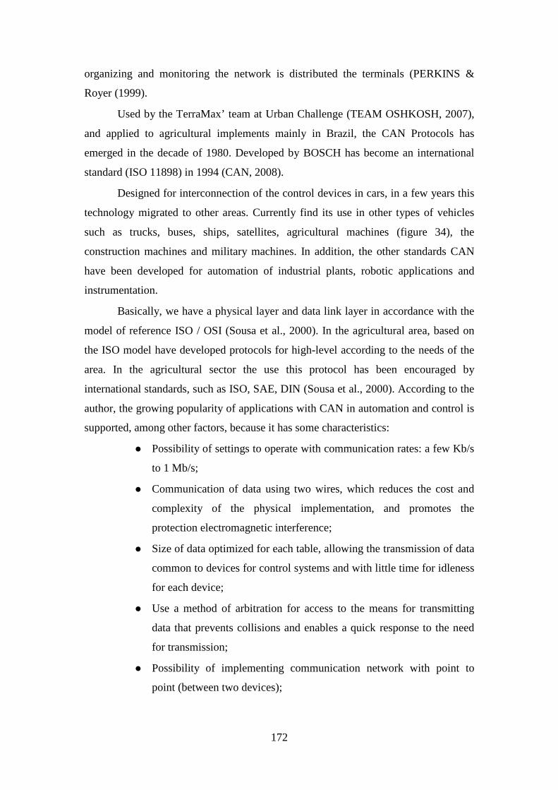
172
organizing and monitoring the network is distributed the terminals (PERKINS &
Royer (1999).
Used by the TerraMax’ team at Urban Challenge (TEAM OSHKOSH, 2007),
and applied to agricultural implements mainly in Brazil, the CAN Protocols has
emerged in the decade of 1980. Developed by BOSCH has become an international
standard (ISO 11898) in 1994 (CAN, 2008).
Designed for interconnection of the control devices in cars, in a few years this
technology migrated to other areas. Currently find its use in other types of vehicles
such as trucks, buses, ships, satellites, agricultural machines (figure 34), the
construction machines and military machines. In addition, the other standards CAN
have been developed for automation of industrial plants, robotic applications and
instrumentation.
Basically, we have a physical layer and data link layer in accordance with the
model of reference ISO / OSI (Sousa et al., 2000). In the agricultural area, based on
the ISO model have developed protocols for high-level according to the needs of the
area. In the agricultural sector the use this protocol has been encouraged by
international standards, such as ISO, SAE, DIN (Sousa et al., 2000). According to the
author, the growing popularity of applications with CAN in automation and control is
supported, among other factors, because it has some characteristics:
� Possibility of settings to operate with communication rates: a few Kb/s
to 1 Mb/s;
� Communication of data using two wires, which reduces the cost and
complexity of the physical implementation, and promotes the
protection electromagnetic interference;
� Size of data optimized for each table, allowing the transmission of data
common to devices for control systems and with little time for idleness
for each device;
� Use a method of arbitration for access to the means for transmitting
data that prevents collisions and enables a quick response to the need
for transmission;
� Possibility of implementing communication network with point to
point (between two devices);
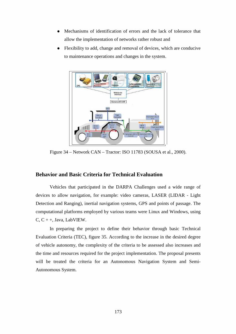
173
� Mechanisms of identification of errors and the lack of tolerance that
allow the implementation of networks rather robust and
� Flexibility to add, change and removal of devices, which are conducive
to maintenance operations and changes in the system.
Figure 34 – Network CAN – Tractor: ISO 11783 (SOUSA et al., 2000).
Behavior and Basic Criteria for Technical Evaluation Vehicles that participated in the DARPA Challenges used a wide range of
devices to allow navigation, for example: video cameras, LASER (LIDAR - Light
Detection and Ranging), inertial navigation systems, GPS and points of passage. The
computational platforms employed by various teams were Linux and Windows, using
C, C + +, Java, LabVIEW.
In preparing the project to define their behavior through basic Technical
Evaluation Criteria (TEC), figure 35. According to the increase in the desired degree
of vehicle autonomy, the complexity of the criteria to be assessed also increases and
the time and resources required for the project implementation. The proposal presents
will be treated the criteria for an Autonomous Navigation System and Semi-
Autonomous System.
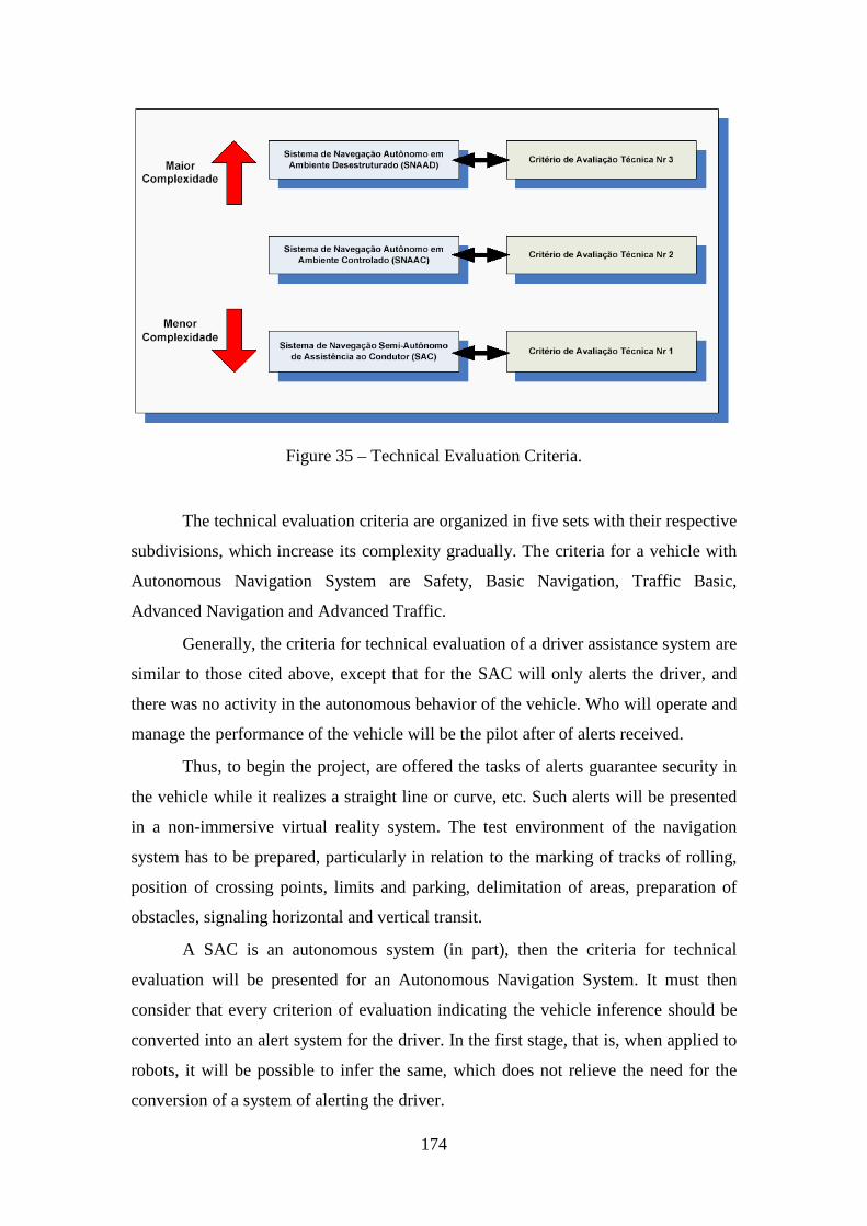
174
Figure 35 – Technical Evaluation Criteria.
The technical evaluation criteria are organized in five sets with their respective
subdivisions, which increase its complexity gradually. The criteria for a vehicle with
Autonomous Navigation System are Safety, Basic Navigation, Traffic Basic,
Advanced Navigation and Advanced Traffic.
Generally, the criteria for technical evaluation of a driver assistance system are
similar to those cited above, except that for the SAC will only alerts the driver, and
there was no activity in the autonomous behavior of the vehicle. Who will operate and
manage the performance of the vehicle will be the pilot after of alerts received.
Thus, to begin the project, are offered the tasks of alerts guarantee security in
the vehicle while it realizes a straight line or curve, etc. Such alerts will be presented
in a non-immersive virtual reality system. The test environment of the navigation
system has to be prepared, particularly in relation to the marking of tracks of rolling,
position of crossing points, limits and parking, delimitation of areas, preparation of
obstacles, signaling horizontal and vertical transit.
A SAC is an autonomous system (in part), then the criteria for technical
evaluation will be presented for an Autonomous Navigation System. It must then
consider that every criterion of evaluation indicating the vehicle inference should be
converted into an alert system for the driver. In the first stage, that is, when applied to
robots, it will be possible to infer the same, which does not relieve the need for the
conversion of a system of alerting the driver.
175
Basic behavior for an Autonomous Navigation System Security
There must be an electronic device to stop emergency, called E-stop, which
must have the ability to perform emergency braking the vehicle. The vehicle must
stop completely, so smooth and controlled, at a distance, pre-determined time, after
activation of E-stop.
Basic Navigation
This criterion is composed by a basic activities set of shipping.
1. Preparing to Move
The vehicle is in autonomous mode and ready to start the shift to 5 minutes
after receiving the Archive of Information Mission (ADM).
2. Mission Begin The vehicle must follow the crossing points of ADM.
3. Crossing Points
The bumper in the vehicle would pass on each point of passage in the ADM in
track and correct in the sequence provided by ADM. The points of passage will be
marked.
4. Stay on Track
The vehicle must remain with all the wheels rolling in its range throughout the
trajectory ride, except when conducting a legal maneuver transit, for example, turn
right or maneuvering to avoid an obstacle.
5. Speed Limits
The vehicle must follow the speed limits, maximum and minimum. When the
vehicle has to stop because of an obstacle, it will not be seen as violation of that
criterion.
6. Delay in Excess
The vehicle must meet the criteria for excessive delay in route, subject to that
responsibility for safe driving (down the occurrence of accidents and collisions).
176
7. Collisions
The vehicle must avoid collisions and near-collisions during the entire journey.
This is the main criterion to be observed. The vehicle must continuously monitor the
way forward looking for vehicles and identifying obstacles to avoid collisions. The
vehicle should not assume that the behavior of another vehicle is completely
predictable.
8. Pedestrian Range / Line Retention
The vehicle must stop before the Range so that the bumper in the vehicle
should be at a safe distance from the middle of the Range. The vehicle must not stop
on the track or block the crossing.
9. Separation of Vehicles
The vehicle must maintain a minimum space on the sides and back of all the
others vehicles and obstacles in all areas of the route. In areas of security, the vehicle
must maintain a minimum distance of the vehicle in front. In the other areas route, the
vehicle must maintain a separation of a vehicle-length. The security areas include
crosses and pedestrian range, a parking area and fields of obstacles.
Begin of passing The vehicle must keep a safety distance from another vehicle or an obstacle fixed in front of it before starting passing another vechile.
1. Returning after passsing The vehicle must return to a determined lane keeping a distance from 1 to 4
times the size of the vehicle that was passed before completing the maneuver.
12. Return
The vehicle must have ability to perform a U-turn.
Traffic Base
This criterion is composed of traffic basic activities set defined in:
1. Basic Navigation
The vehicle must meet all criteria for basic navigation.
2. Precedence of Intersection
The vehicle must comply with the order of precedence at the intersections. The
basic rule of precedence in an intersection that is the first vehicle to stop on the range
is the first vehicle to leave. The vehicle entering the intersection, he must
177
continuously monitor the other vehicles and the path ahead to eliminate the possibility
of collision.
3. Minimum distance to Follow The vehicle must maintain a distance from the vehicle in front when moving
traffic. Criterion is consistent when applied to the traffic moving, with different
distances of separation in traffic and security areas.
4. Behavior in Row The vehicle must display appropriate behavior when in a row of stopped cars,
always keeping the distance to the vehicle ahead. This distance should range from one
to two lengths of the vehicle.
Advanced Navigation
This criterion is composed of a advanced navigation activities set, as defined
in:
1. Traffic Base
The vehicle must meet all criteria for traffic base.
2. Field of Obstacles The vehicle must be able to handle field of obstacles efficiently and safely.
The vehicle must be able to operate in an uneven area where there is no appropriated
signalizing devices. Such areas may or may not be paved or have marks on the
ground. The vehicle must be able to determine whether the slope upstream or
downstream is different from a similar configuration like a stairway, avoiding
confusion, for example, with some entries of buildings that have this feature. The
vehicle must avoid collisions and keep safe distance from the vehicle / obstacle ahead.
It is possible to have static obstacles (trees, rocks) and dynamic (vehicles). To avoid
collisions, once detected displacement of another vehicle in the opposite direction, the
vehicle must adopt the general rule of shifting to the right and then proceed forward,
if that possibility before consulting offers no additional risk.
3. Parking
The vehicle must display appropriate behavior to achieve parking. For this
purpose, the vehicle should move via a point of entry, go through a second point of
control, both marked on the pavement, park and respecting the limits of vague. To
exit, must observe the same set of rules backyard. The parking space is bounded by
178
tracks on the pavement. Special care should be given to those areas where there is a
gap in front of the parking space, like empty slots located in buildings-parking.
4. Re-planning Dynamic
The vehicle must be able to reach the crossing points provided even when the
roads are blocked. The blocking of roads will not be provided for Archive Definition
of Route (ADR). The route may be blocked by parked vehicles, etc. There will always
be an alternative route to allow the continuation of the mission. The vehicle must
remain on track and make a U-turn, planning an alternate route. The use of back
command is limited to the distance of 3 lengths of the vehicle.
5. Follow the path
The vehicle must have ability to navigate in the process of crossing points with
sparse and remain in the range of rolling following the limits of the track, the track
itself or use another technique for sensing for this purpose. The vehicle should still be
able curve of 90 ° without need of a dense set of crossing points.
6. GPS
The vehicle must not show excessive delay or abandon the track of rolling due
to loss of signals from the GPS navigation. A unit of inertial navigation or another
technique should be used to allow the vehicle to continue with track safety on the
route, possibly at reduced speed, until the signal of GPS is restored.
Advanced Traffic
This criterion is composed of a advanced traffic activities set, as defined in:
1. Advanced Navigation
The vehicle must meet all criteria for advanced navigation.
2. Traffic Fusion
The vehicle must always enter the movement of traffic when there is time
before the safe arrival of the next vehicle. The vehicle can travel at a safe period of
time when conditions so permit. The vehicle that enters the traffic must accelerate so
that the vehicle that will distance ago maintains security and constant speed.
3. Separation of vehicles during the Traffic Fusion
The vehicle must be able to come into range of rolling between two vehicles in
traffic moving. The vehicle must maintain a safe distance in front of the vehicle and
the vehicle that comes ago should not need to reduce or stop their displacement.

179
4. Turn Left
The vehicle must allow turn left, crossing a track that has bearing traffic in the
opposite direction to their displacement when a safe time to another vehicle that
comes in the opposite direction. If conditions permit, the vehicle can complete the
curve in an indefinite period, according to previous rules.
5. Separation of Vehicles During Turn Left
After making a turn left and cross a strip of rolling, the vehicle must maintain
a safe distance from at least 2 vehicles to avoid collisions in length, without causing
reduced or stopped in traffic.
6. Zones
The vehicle must be able to navigate in areas in an effective and safe in the
presence of moving traffic or other obstacles. Traffic moving into areas creates a
challenge for the lack of lanes of traffic.
7. Emergency Stop
The vehicle must stop completely and safely to avoid collision when an
obstacle suddenly moves in the range of bearing. The time of anticipation should have
a safe margin of time. Thus, for a moving vehicle, the system must be able to stop
safely when the obstacle ahead.
8. Defensive Direction
The vehicle must perform defensive direction to avoid collisions imminent and
to maintain the distance between vehicles. The vehicle must deal with traffic at speeds
of approximation secure. The vehicle must be able to detect vehicle approximation,
recognize the threat and perform evasive maneuver to avoid collision.
9. Blocking Traffic
The vehicle must be able to perform maneuvers to continue and avoid collision
with a partially blocked intersection. In an intersection in which such a blockage
occurs in part, the vehicle must wait a safe time to establish order of precedence
before continuing on the crossing and redefine the new route to reach the next point of
passage.
180
Hardware and Systems Architecture For a vehicle or robot as a platform for development, particular attention to the
following:
� Item A - Hardware Project (computers, sensors): real vehicle;
� Item B – System Architecture: applies to two stages of the proposal;
For the first stage of research, it is the use robots of smaller scale, as example
of robotic platforms. Besides the reduced size, the robot can be accompanied by
several additional equipment, such as transmitter / receiver for radio communication,
camcorder, for studies of vision loaded, and so on. Also, can be controlled through
LabView software and Matlab, or directly through words of control sent to the port of
a computer, without the need of acquiring any additional software.
Hardware Project
Computers
To support the Vision Systems should be used personal computers PC Quad-
Core Intel, structured with synchronized and hierarchical, and suitable to the
environment of the vehicle. The experience of teams that participated in other editions
of the DARPA Challenge showed that normally is used a computer for each system /
sensor. Thus, the initial estimate is at least one and no more than 4 (four) for the PC
Vision System (trinocular, close range stereo, rear view, side view). The exact amount
of machinery will be determined after the tests and the integration of systems / sensors
and defining the scope of the project.
Sensors
Sensors are very important components for navigation. Initially, there are
estimates of a Vision and Laser System.
Vision System
The Vision System (SV) is to enable the system "see" the outside environment.
It is intended to be composed of selection of video-cameras and Laser System.
LIDAR System
The LIDAR system is to achieve precise measures of distance, speed and
detection of objects. His purchase / use will be subject to review during the project.
181
Architecture System
The system architecture is composed of Architecture Logic and
Implementation of Architecture, discussed below.
Architecture Logic
The system architecture is adhering to the diagram of architecture in layers. In
the diagram of architecture in layers, addiction always flow down, that is, each layer
depends only on the bottom layer. This architecture facilitates a clear separation of
functionality and development of well-defined interfaces between subsystems. This
will develop the subsystems independently without impact on the cohesion of the
system (Figure 36).
The Control System and User Interface is the block of higher hierarchy in
architecture. It is here that will be carried out monitoring of the situation of the
vehicle, the management of the service and view the route.
The Autonomous Navigation is the structure responsible for conducting the
performance of tasks and planning routes.
The Management of the vehicle and perception for Navigation is the third
level of the hierarchy of architecture logic. The first block is related activities such as
the following points of passage, monitoring and control of stability. The second
section deals with issues concerning the detection of obstacles, detection of routes,
identification of areas on the roughness, traffic, detecting signs of horizontal (range of
pedestrians, direction of traffic, etc.).
Architecture for Implementation
The implementation architecture is divided into two main blocs: Services
System and Autonomous Services. The first includes diagnosis vehicular systemic,
service and control setup and display. The second block covers services sensing
services, autonomous behavior, perception of services and services for managing
vehicle.
1. Autonomous Services
Autonomous Services is part of the system responsible for obtaining
information from the environment and the vehicle. It is composed of Autonomous
Vehicle Manager, Navigation System, server state, Perception Server, Server
Navigation, and several sensors.
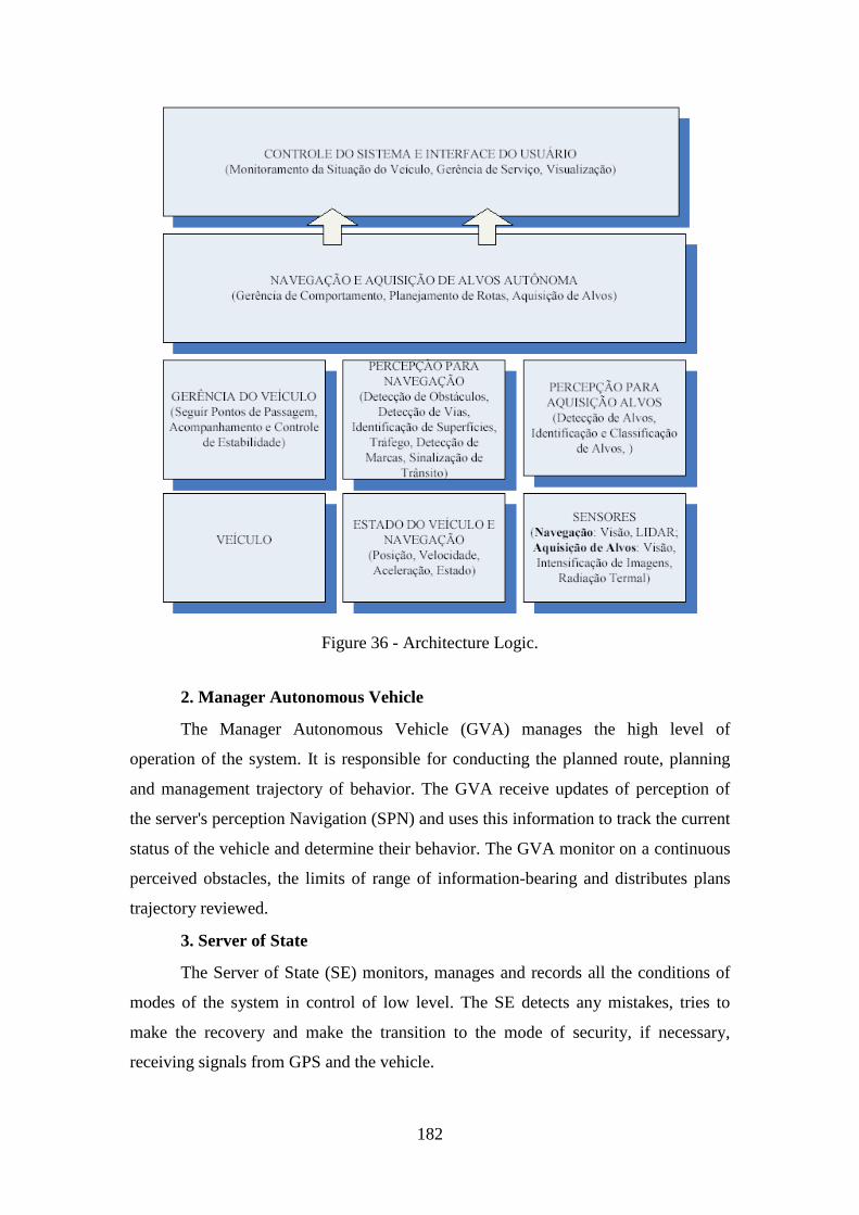
182
Figure 36 - Architecture Logic.
2. Manager Autonomous Vehicle
The Manager Autonomous Vehicle (GVA) manages the high level of
operation of the system. It is responsible for conducting the planned route, planning
and management trajectory of behavior. The GVA receive updates of perception of
the server's perception Navigation (SPN) and uses this information to track the current
status of the vehicle and determine their behavior. The GVA monitor on a continuous
perceived obstacles, the limits of range of information-bearing and distributes plans
trajectory reviewed.
3. Server of State
The Server of State (SE) monitors, manages and records all the conditions of
modes of the system in control of low level. The SE detects any mistakes, tries to
make the recovery and make the transition to the mode of security, if necessary,
receiving signals from GPS and the vehicle.
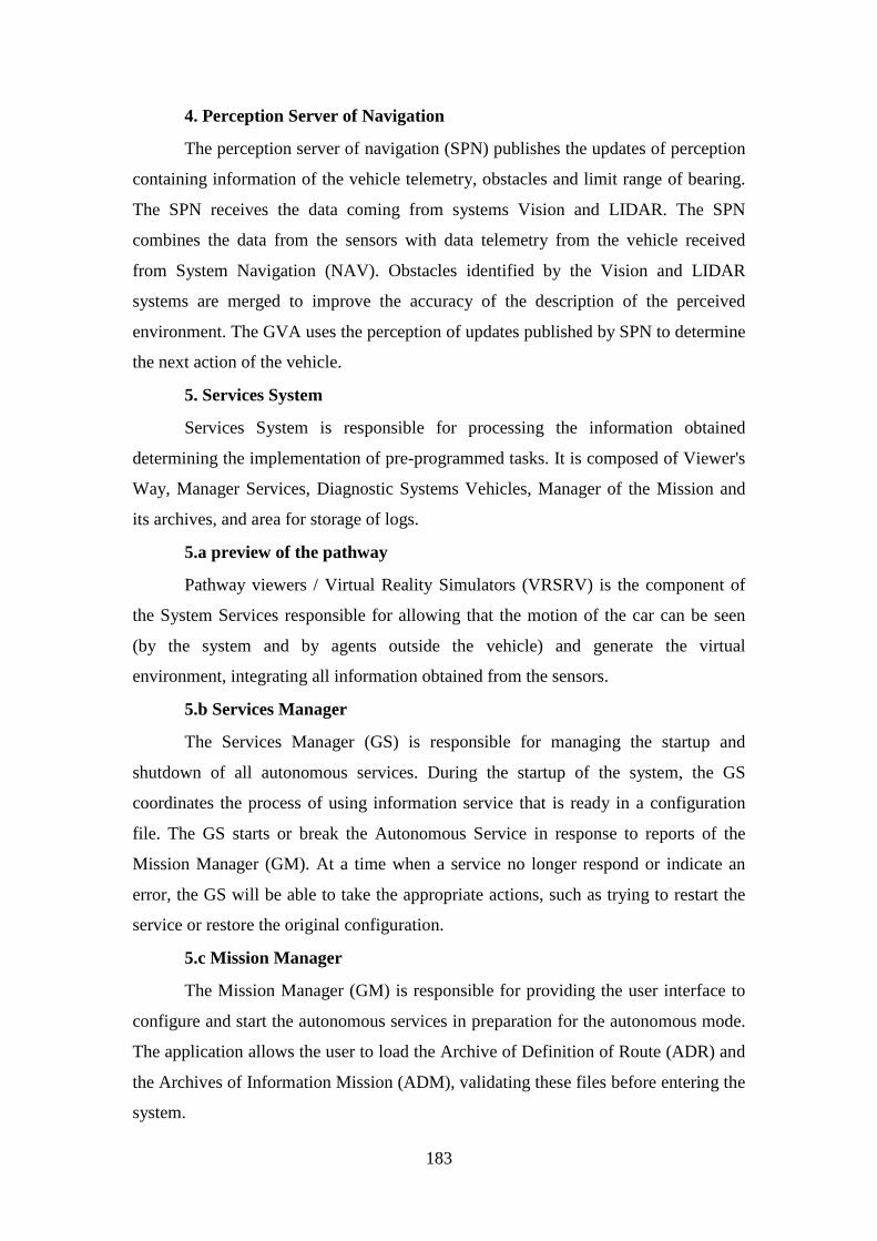
183
4. Perception Server of Navigation
The perception server of navigation (SPN) publishes the updates of perception
containing information of the vehicle telemetry, obstacles and limit range of bearing.
The SPN receives the data coming from systems Vision and LIDAR. The SPN
combines the data from the sensors with data telemetry from the vehicle received
from System Navigation (NAV). Obstacles identified by the Vision and LIDAR
systems are merged to improve the accuracy of the description of the perceived
environment. The GVA uses the perception of updates published by SPN to determine
the next action of the vehicle.
5. Services System
Services System is responsible for processing the information obtained
determining the implementation of pre-programmed tasks. It is composed of Viewer's
Way, Manager Services, Diagnostic Systems Vehicles, Manager of the Mission and
its archives, and area for storage of logs.
5.a preview of the pathway
Pathway viewers / Virtual Reality Simulators (VRSRV) is the component of
the System Services responsible for allowing that the motion of the car can be seen
(by the system and by agents outside the vehicle) and generate the virtual
environment, integrating all information obtained from the sensors.
5.b Services Manager
The Services Manager (GS) is responsible for managing the startup and
shutdown of all autonomous services. During the startup of the system, the GS
coordinates the process of using information service that is ready in a configuration
file. The GS starts or break the Autonomous Service in response to reports of the
Mission Manager (GM). At a time when a service no longer respond or indicate an
error, the GS will be able to take the appropriate actions, such as trying to restart the
service or restore the original configuration.
5.c Mission Manager
The Mission Manager (GM) is responsible for providing the user interface to
configure and start the autonomous services in preparation for the autonomous mode.
The application allows the user to load the Archive of Definition of Route (ADR) and
the Archives of Information Mission (ADM), validating these files before entering the
system.
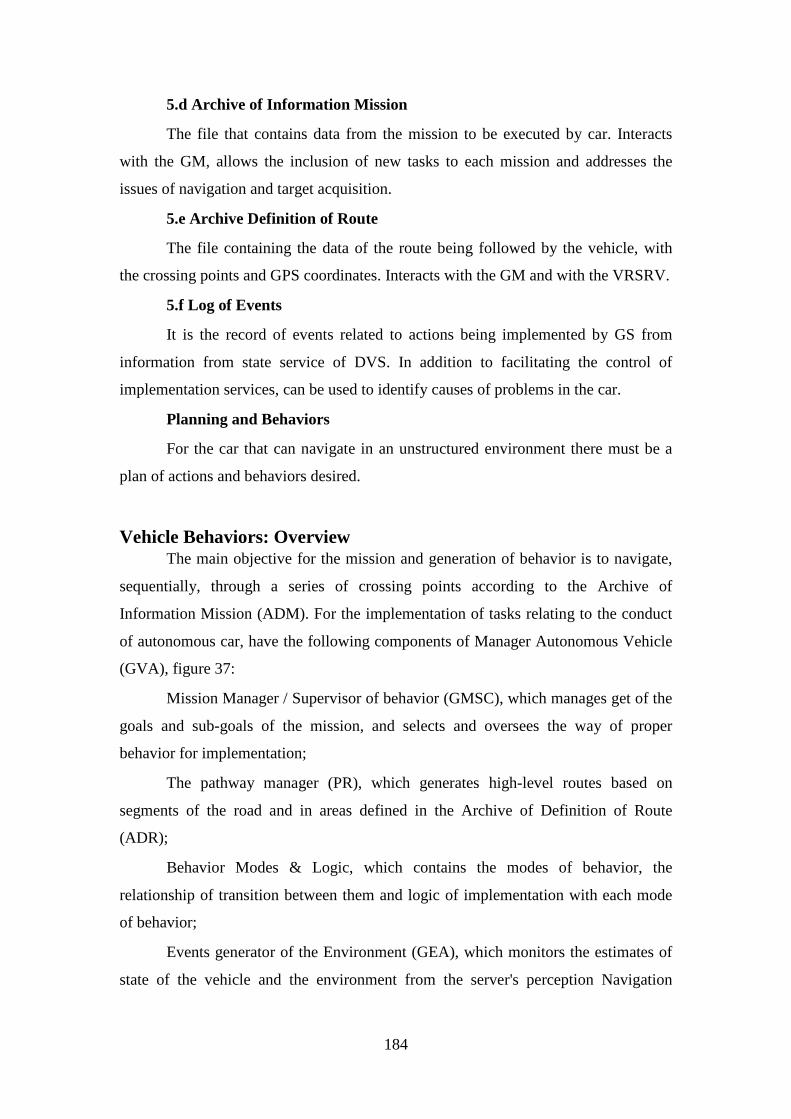
184
5.d Archive of Information Mission
The file that contains data from the mission to be executed by car. Interacts
with the GM, allows the inclusion of new tasks to each mission and addresses the
issues of navigation and target acquisition.
5.e Archive Definition of Route
The file containing the data of the route being followed by the vehicle, with
the crossing points and GPS coordinates. Interacts with the GM and with the VRSRV.
5.f Log of Events
It is the record of events related to actions being implemented by GS from
information from state service of DVS. In addition to facilitating the control of
implementation services, can be used to identify causes of problems in the car.
Planning and Behaviors
For the car that can navigate in an unstructured environment there must be a
plan of actions and behaviors desired.
Vehicle Behaviors: Overview The main objective for the mission and generation of behavior is to navigate,
sequentially, through a series of crossing points according to the Archive of
Information Mission (ADM). For the implementation of tasks relating to the conduct
of autonomous car, have the following components of Manager Autonomous Vehicle
(GVA), figure 37:
Mission Manager / Supervisor of behavior (GMSC), which manages get of the
goals and sub-goals of the mission, and selects and oversees the way of proper
behavior for implementation;
The pathway manager (PR), which generates high-level routes based on
segments of the road and in areas defined in the Archive of Definition of Route
(ADR);
Behavior Modes & Logic, which contains the modes of behavior, the
relationship of transition between them and logic of implementation with each mode
of behavior;
Events generator of the Environment (GEA), which monitors the estimates of
state of the vehicle and the environment from the server's perception Navigation
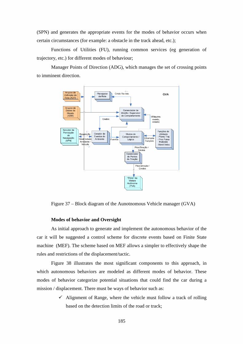
185
(SPN) and generates the appropriate events for the modes of behavior occurs when
certain circumstances (for example: a obstacle in the track ahead, etc.);
Functions of Utilities (FU), running common services (eg generation of
trajectory, etc.) for different modes of behaviour;
Manager Points of Direction (ADG), which manages the set of crossing points
to imminent direction.
Figure 37 – Block diagram of the Aunotnomous Vehicle manager (GVA)
Modes of behavior and Oversight
As initial approach to generate and implement the autonomous behavior of the
car it will be suggested a control scheme for discrete events based on Finite State
machine (MEF). The scheme based on MEF allows a simpler to effectively shape the
rules and restrictions of the displacement/tactic.
Figure 38 illustrates the most significant components to this approach, in
which autonomous behaviors are modeled as different modes of behavior. These
modes of behavior categorize potential situations that could find the car during a
mission / displacement. There must be ways of behavior such as:
� Alignment of Range, where the vehicle must follow a track of rolling
based on the detection limits of the road or track;
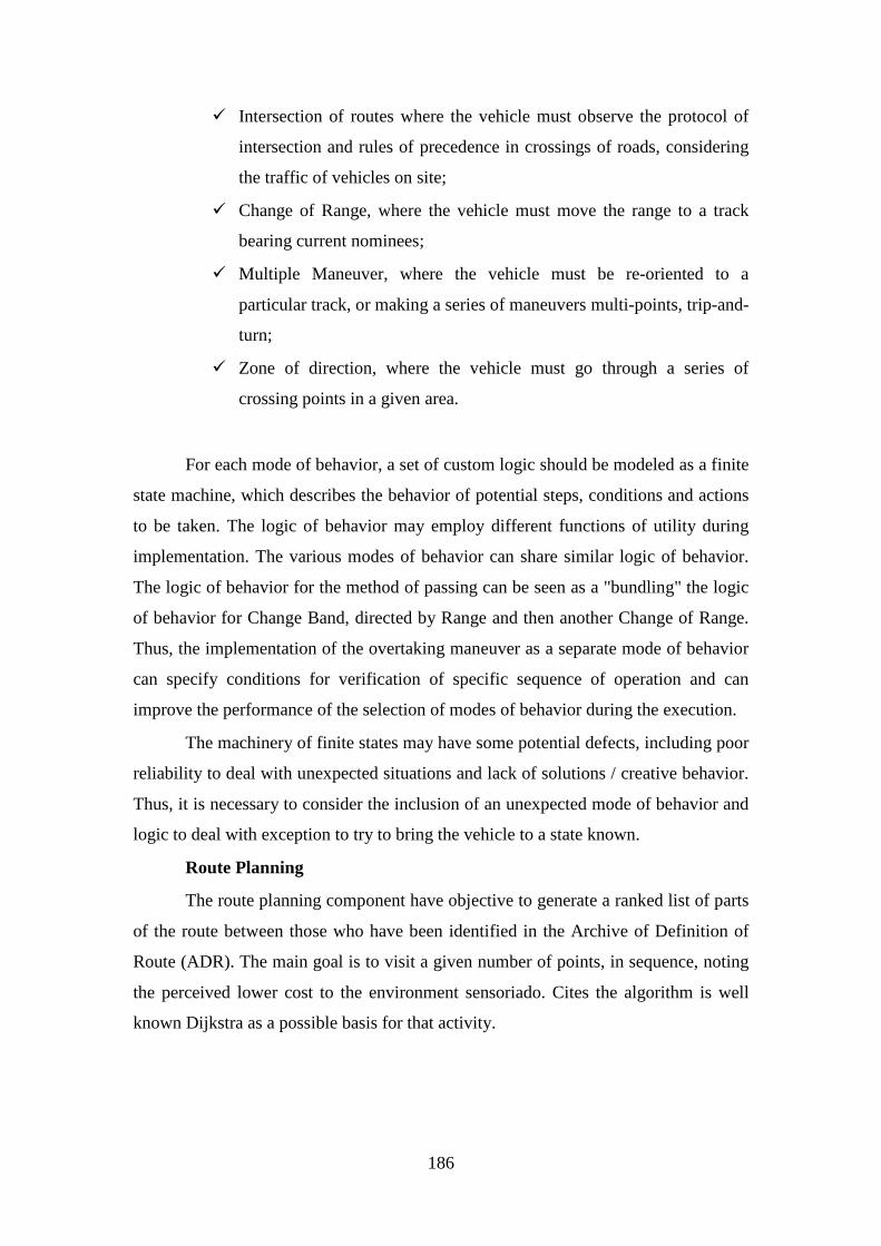
186
� Intersection of routes where the vehicle must observe the protocol of
intersection and rules of precedence in crossings of roads, considering
the traffic of vehicles on site;
� Change of Range, where the vehicle must move the range to a track
bearing current nominees;
� Multiple Maneuver, where the vehicle must be re-oriented to a
particular track, or making a series of maneuvers multi-points, trip-and-
turn;
� Zone of direction, where the vehicle must go through a series of
crossing points in a given area.
For each mode of behavior, a set of custom logic should be modeled as a finite
state machine, which describes the behavior of potential steps, conditions and actions
to be taken. The logic of behavior may employ different functions of utility during
implementation. The various modes of behavior can share similar logic of behavior.
The logic of behavior for the method of passing can be seen as a "bundling" the logic
of behavior for Change Band, directed by Range and then another Change of Range.
Thus, the implementation of the overtaking maneuver as a separate mode of behavior
can specify conditions for verification of specific sequence of operation and can
improve the performance of the selection of modes of behavior during the execution.
The machinery of finite states may have some potential defects, including poor
reliability to deal with unexpected situations and lack of solutions / creative behavior.
Thus, it is necessary to consider the inclusion of an unexpected mode of behavior and
logic to deal with exception to try to bring the vehicle to a state known.
Route Planning
The route planning component have objective to generate a ranked list of parts
of the route between those who have been identified in the Archive of Definition of
Route (ADR). The main goal is to visit a given number of points, in sequence, noting
the perceived lower cost to the environment sensoriado. Cites the algorithm is well
known Dijkstra as a possible basis for that activity.
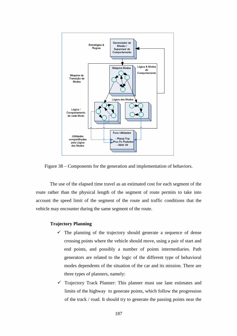
187
Figure 38 – Components for the generation and implementation of behaviors.
The use of the elapsed time travel as an estimated cost for each segment of the
route rather than the physical length of the segment of route permits to take into
account the speed limit of the segment of the route and traffic conditions that the
vehicle may encounter during the same segment of the route.
Trajectory Planning
� The planning of the trajectory should generate a sequence of dense
crossing points where the vehicle should move, using a pair of start and
end points, and possibly a number of points intermediaries. Path
generators are related to the logic of the different type of behavioral
modes dependents of the situation of the car and its mission. There are
three types of planners, namely:
� Trajectory Track Planner: This planner must use lane estimates and
limits of the highway to generate points, which follow the progression
of the track / road. It should try to generate the passing points near the
188
center lane of the track. Initially, the planner should generate the points
estimating the center lane using the limits of the range detected on
either side of the track and incorporate in this information the limits of
the highway and the standard width of the track near the passing point.
Aftewrad, the planner must verify and remove potential points of
passing out of order and apply an algorithm, possibly based on cubic
splines, to generate more smother points.
� Modeled Trajectory Planner: This set of planners must be able to
generate points of the trajectory based on reference models with
estimates of the current state of the environment and the car to be used
for joint maneuvers such as changing lanes, overtaking and look at
intersections.
� Open Space Trajectory Planner: This planner must provide generation
of trajectory and avoid obstacles in a predetermined area where
obstacles may be present.
189
Themes and Research Areas In accordance with the basic research areas of interest described in the
invention report MCT Nº429, the current proposal mainly addresses: Science, technology and innovation for homeland security and public safety.
� The institute, gathered as a network with main research focus in Terrestrial Mobility, will mainly develop research in the following area:
Autonomous Navigation
This activity will be pursued by the laboratory of Robotic Navigation an Virtual Reality located at the department of computational mechanics of the school of mechanical engineering of UNICAMP
As exposed by Francisco Bonin-Font e his co-works in a recent article
published in the Journal of Intelligent and Robotic Systems, robotic navigation is related to the process of determining one feasible trajectory between two points, using signal measured from distinct sensors. For the autonomous air or land navigation, the most used sensor is the vision, on the other hand, water navigation systems uses acoustical signals as data.
In general, navigation system can be subdivided into two classes:
� Previously known environment;
� Unknown environment.
The later class is generally denominated as navigation systems without maps and has been of great interest to the military community.
The Department of Computational Mechanics has a tradition in the field of robotic navigation for autonomous systems that must be able to maneuver on hazardous environments, providing promising theoretical results (and more recently practical ones) using mainly neural networks and image processing. Preliminary results were based on the morphology of the hippocampus, the organ responsible for the sense of orientation in human been, and on the conexionist learning approach of Gagnet. The theoretical results and the simulated results were satisfactory for different configurations of the environment, were the neural network performed well for most of the cases. Results using (mono) vision with sensor to identify the environment were also obtained. These results were presented in a master thesis in which a preliminary prototype, quite simple, was developed. The system consisted of two servomotors in open-loop, with an acquisition system that uses a cellular camera. Although the experiment was simple, the proposed robust and fast image processing system provided results close to the one obtained on real applications. The acquisition process based on Otsu, was denominated TH Finder.
190
This research line can be characterized by ongoing development obtained until now. Basically, there are two lines: In the first level, theoretical and simulated results are seek, were the idea is to develop a methodology for autonomous navigation using a platform that can emulate signals from different sensors used in practice. Some of these platforms are the Microsoft Robotics Studio, that was used by the Pittsburgh team at the DARPA Grand Challenge.
The second phase consists on implementing an off-road vehicle with a minimal level of automation (electrically assisted orientation, active breaking and altitude control, etc). This topic will be executed in close cooperation with the other groups of the project.
As identified by many authors and research groups in the area, the system motions are functions of the measurements (with or without noise) of the environmental conditions, which are usually performed using optical flow and navigation based on the appearance. Since, the aim is also to maneuver in hostile environments, two situations can occur: a random navigation that happens frequently in aerospace missions and navigation with a specific target, which is the main goal of this proposal. One promising technique that has been recently used is the mapping performed simultaneously with the localization. The classical approach is the generation of 3D maps using stereo vision. As can be observed, these proposed research lines will be the cornerstone for the development that will emerge in the others laboratories, in particular, at the vision and inertial navigation laboratory. Summarizing, from the previous developments using neural networks and image processing, the goal is to construct a virtual prototype that will be able to navigate in different types of unknown terrains in the presence of obstacles. The prototype will be tested on uneven grounds only after the validation of the control and identification methodologies used in the system. It will also depend on the active suspension system to be developed for the vehicle.
Perception and Communication Networks
Activities undertaken by the Real-Time Perception Based on Sensors and Communications Network Laboratories of the Telecommunications Engineering and Control Department of the Polytechnic School of USP
The aid to the people, by automated systems is trend resulting of technological developments. Its application to the Public Security and National Defence, for example, helping vehicles drivers on roads and public roads, and in cases of war or hostility of major enemy, its value has increased considerably as a treat to save lives. In Brazil, research indicates that around 40 thousand people lose their lives each year in accidents in transit.
Many search teams of the United States has achieved excellent results in autonomous vehicles. An example is the team at Stanford University, led by Sebastian Thrun. In 2005, this group won the DARPA Grand Challenge with the autonomous vehicle, nicknamed Stanley. The architecture of the robot Stanley was divided into six large blocks: sensor interface, perception, planning and control, user interface, vehicle interface and global services, as shown in figure below.
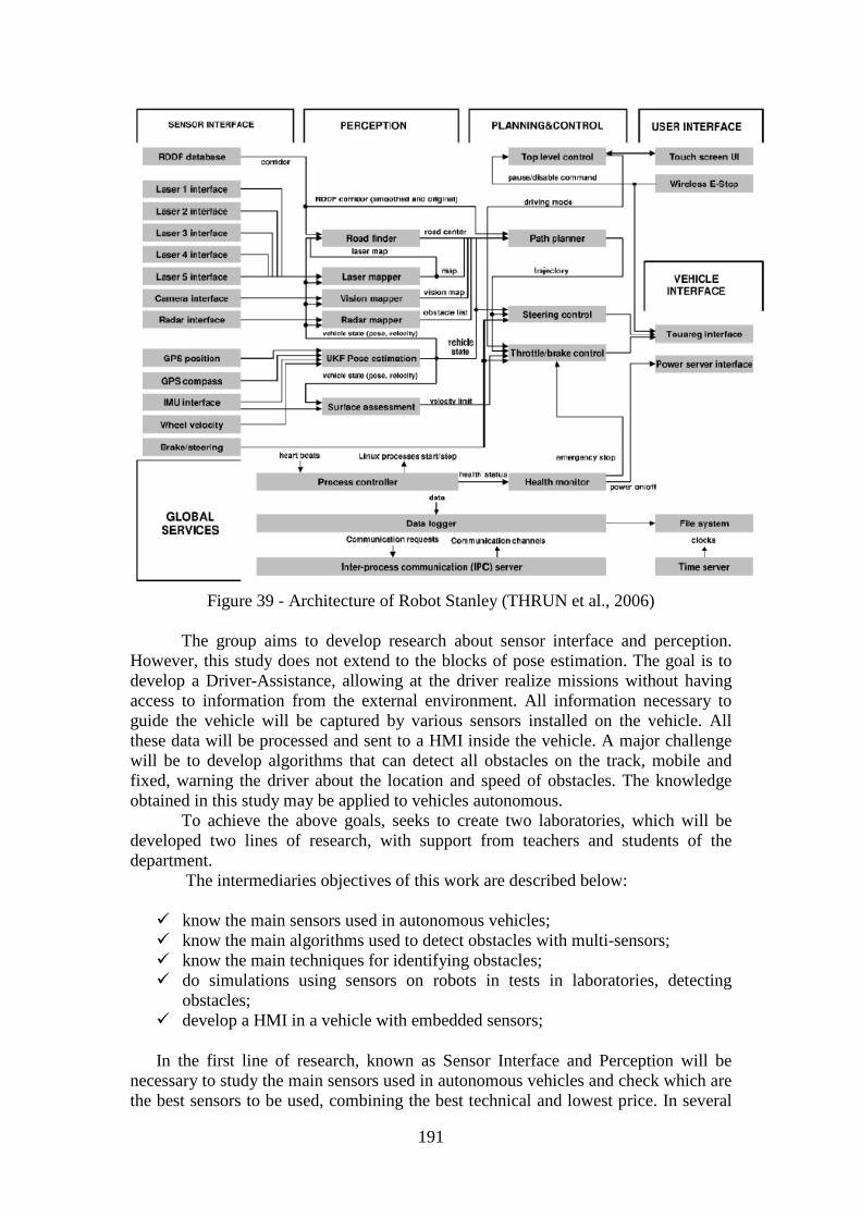
191
Figure 39 - Architecture of Robot Stanley (THRUN et al., 2006) The group aims to develop research about sensor interface and perception.
However, this study does not extend to the blocks of pose estimation. The goal is to develop a Driver-Assistance, allowing at the driver realize missions without having access to information from the external environment. All information necessary to guide the vehicle will be captured by various sensors installed on the vehicle. All these data will be processed and sent to a HMI inside the vehicle. A major challenge will be to develop algorithms that can detect all obstacles on the track, mobile and fixed, warning the driver about the location and speed of obstacles. The knowledge obtained in this study may be applied to vehicles autonomous.
To achieve the above goals, seeks to create two laboratories, which will be developed two lines of research, with support from teachers and students of the department.
The intermediaries objectives of this work are described below:
� know the main sensors used in autonomous vehicles; � know the main algorithms used to detect obstacles with multi-sensors; � know the main techniques for identifying obstacles; � do simulations using sensors on robots in tests in laboratories, detecting
obstacles; � develop a HMI in a vehicle with embedded sensors;
In the first line of research, known as Sensor Interface and Perception will be necessary to study the main sensors used in autonomous vehicles and check which are the best sensors to be used, combining the best technical and lowest price. In several
192
studies, are employed various types of sensors such as laser, radar, sonar and stereo vision. There is a need to know each type of sensor, identifying its main characteristics, operations, limitations, costs, communication protocol and external conditions that may be submitted. A major challenge will be to develop a block that recognize signals from various types of sensors and make the integration of them.
Important aspects to be verified:
� Correcting inaccurate measures of sensors; � Compensation of unwanted influences in the measurement; � Making of patterns and characteristics of the signal; � Removal or reduction of noise; � Sensor fusion
The main task of the Perception is to integrate the signals from various sensors to confirm whether there is an obstacle and to determine exactly how distance and speed information from the vehicle. Important aspects to be verified:
� Kalman’s Filters � Filtering � Image Processing � Recognition of Standards � Optical Flow; � Mapping; Algorithms Measurement; � Prediction of collision.
The second line of research, involving networks of communication, a more
thorough detail was presented in the introduction to this project and will not be
repeated here.
Inertial Navigation
This activity will be developed by the Inertial Navigation Laboratory of Mechanical Engineering from Military Engineering Institute.
Inertial navigation is defined as the determination of the position, velocity and angular orientation (attitude) of a vehicle regarding a system of coordinates. A ISN (Inertial Navigation System) is a system wich uses a computer and motion sensors, to calculate continuously the position, direction and speed of a vehicle without the need for external references such as the Global Positioning System (GPS), for example, what makes it self-contained (SAVAGE, 1998a). This advantage makes the SNI unique and very attractive for applications in navigation (SAVAGE, 1998b), (BEKIR, 2007).
Inertial navigation systems have a huge range of applications, and can be used in different kinds of vehicles, such as aircraft, missiles, submarines, torpedoes, ships, floating platforms, cars, etc. Like any method, the inertial navigation has advantages and disadvantages. Uncertainties on track as a result of errors accumulated over time,
193
is its main drawback. These errors are originated, mainly, from errors inherent to the measurement and the integration processes of signs of acceleration and speed. This disadvantage can be minimized by the integrated use of the INS integrated to other non-inertial sensors, such as GPS, baroaltimeter, the magnetometer, etc. If it is chosen to integrate the GPS to the INS, for example, we have an Integrated Inertial Navigation System / GPS (INS / GPS). Since the GPS also has its own error components in the provided information, it is necessary to use a method of sensor fusion to make this integration and thus provide the highest possible accuracy with the desired parameters (LITMANOVICH et al., 2000).
Among the methods of data fusion, the Kalman filter is the one with the best results. It states, according to a optimization criterion, the navigation data from inertial sensors measures, by means of a deterministic model wich describes the dynamics of the ISN errors, and a model that describes the behavior of stochastic measurement errors of inertial sensors (SHIN, 2001), (BEKIR, 2007). Therefore, the quality of the estimation obtained by Kalman filter depends on the accuracy of the measures provided by the IMU (Inertial Measurement Unit) and the performance of the adopted models. Therefore, the performance of INS, is directly related to the quality of accelerometers and gyroscopes (PINTO DE SOUZA, 2007) and (ROCHA, 2006).
In the context of simulation and hardware implementation, advances in this area may be attributed not just to the computational power achieved in recent years, but also to new mathematical formulations, which have an important role in the improvement of the speed of prototype implementation. An example is the Real Time Workshop of the software Matlab of the Mathworks. Until then, the development of real-time applications require a good knowledge of programming languages for real time and sometimes even a deep knowledge of numerical methods.
An interesting way to overcome that is offered by the Matlab / Simulink / Real Time Workshop, or simply RTW. The RTW (Real Time Workshop) is an automatic C code generator with directives of real time for the Simulink. With the Simulink is possible to create, simulate and analyze complex dynamic systems with simple connections between functional blocks, most of which are already available in many pre-configured libraries with a friendly graphical interface. The main advantage lies on the use of a simple mathematical notation to express the problem as well as visualization and analysis of any signal of the model. With such a tool, one can focus strictly on the problems of modeling and control rather than spend considerable time in programming problems. It is the RTW then, which controls the translation of the model created in simulink for a number of functions in C which also is compiled and linked to obtain an executable file.
The development of inertial navigation started up around 1900 in Germany
and in the United States seeking military applications. With the mastery of techniques, its use was expanded to civilian applications. Of the many applications of inertial systems can be highlighted:
� Navigation, Guidance and control of ships, submarines and aircraft; � Guidance of torpedoes and missiles of short, medium and long range; � Geodesy and Cartography;
194
� Robotics, UAV (Unmanned Aerial Vehicle), ASV (Autonomous Submarine Vehicle) and AGV (Autonomous Ground Vehicle);
� Platforms Stabilization (for shooting, oil extraction, filming equipment);
� Space missions (launching satellites); � Satellites Stabilization; � Tracking trajectory of oil drilling; � Guidance, navigation and control of vehicles when it is employed in
agressive regions or in tactics situations; � Georeferencing system of Pipelines using inertial PIG (Pipeline
Inspection Gauge); � Autonomous ground vehicles; � Entertainment Industry; � Topographic Mapping; � Structural Failure Detection through vibration analysis.
The objective of this work is the simulation and implementation of an inertial
navigation system with real-time algorithm, integrated to GPS in order to assist in the navigation of an AGV (Autonomous Ground Vehicle).
With the start of the Program of Graduate Courses on Defense Engineering (PGED) in February 2007, the Institute seeks effectively aim its courses and research to the field of Defense and to the needs of the Brazilian Army (EB). This goal is in line with directives of the Department of Science and Technology (DCT) of the EB and the National Defense Policy, launched in June 2005 by the Ministry of Defense, regarding the training of scientific and technological forces Armed.
The PGED aims to meet the national demand for highly skilled staff and specialized, investing in a solid formation in basic research, quality and international integration. The courses of PGED have as main purpose to enable the graduate students to perform activities of research and teaching, training military and civilian students to extend and to get deeper in their knowledge in different areas of engineering and sciences linked to the problems of interest for Defense National.
The Research Lines (LP) of PGED seek to consolidate the various researches in Defense dispersed by the Institute as well as promote the development of critical areas for the EB, such as the LP Mechatronics and Weapons Systems, where at the moment is grounded a solid basis for research in the field of Navigation and Inertial Systems.
Through the project Georeferencing Pipeline System, CT-DUT/FINEP (2007-2008), was established a research group on inertial systems at IME, basically involving professional specialization. Since then, it were already presented two master dissertations in the area, with two more in progress. Besides, IME was the host institution of the Brazilian Symposium on Inertial Engineering 2007, and its members presented several works during the symposium. Moreover, the IME participated in the creation of the Brazilian Society of Inertial Engineering, in wich is represented by two members of the staff of this proposal.
195
Through this project it is intended to consolidate the group of research in inertial systems, and to promote the training specialization in this area through the graduate course programs in Mechanical, Electrical and Defense Engineering. In addition, it is intend to install the Inertial Sensors and Navigation Laboratory, to provide physical structure to strengthen the area.
To achieve the primary objective of the project, many options should be considered, such as the use of an discrete algorithm, which is more appropriated for hardware implementation and also for real time programming. The biggest advantage of using discrete algorithms is the ability to use smaller sample rates, allowing the use of more modest and cheaper processors, and still get results very close to reality. In spite of processing speed not to be a so critical problem as the decades of 60 to 90, in navigation applications it is still important.
As a platform for simulation and implementation of real-time algorithm for navigation, can be used a software package as the MATLAB®/Simulink with the toolboxs Real Time Workshop and xPC Target. The Real Time Workshop generates and optimizes codes portable and customizable ANSI C or C++ models of Simulink to create specific implementations of models that operate in real time. The generated code can run on PCs, microcontrollers and DSPs and still run on any operational real-time system (RTOS).
The xPC Target is an environment for prototyping, testing and development of systems that operate in real time to computer standards. He uses a computer target, separated from the host computer, to run applications in real time. A computer target can be virtually any computer with an Intel 386 or 486 or AMD K5 or K6/Athlon, can be a desktop computer or a computer industry as a PC104 which will be used in this work. From a simulation normally created in Simulink, you can generate an executable code from the RTW, towards the very xPC Target. The executable code and xPC Target real-time kernel is then recorded on the computer host to the target. Then you can run the application in real time, with the possibility of change "online" the parameters of the model.
Thus, some steps can be established for the development of work:
1. Study of the navigation problem in AGVs, definition of navigation and instrumentation architecture.
2. Study about accelerometers and gyrometers, analyzing principles and the application of appropriate technologies for a navigation AGV.
3. Development of a signal generator that simulates the behavior of the AGV variables of interest to navigation.
4. Development of instrumentation model. 5. Development of the algorithm of integrated navigation. 6. Study of standards for testing and practical procedures (in Brazil): Essays
main normally executed and standards followed, manufacturers, etc. 7. Tests to select the sensor to be applied to an AGV. 8. Implementation of the integrated unit INS / GPS. 9. Test of the integrated unit INS / GPS alone. 10. Test of the integrated unit INS / GPS assembled to an AGV.
196
Computer Vision
This activity will be developed by the Computer Vision Laboratory of Department of Computer Engineering and Industrial Automation (DCA) at the School of Electrical and Computer Engineering (FEEC), State University of Campinas (Unicamp).
In general, for autonomous and semi-autonomous navigation systems, the
vision system senses the environment in the surroundings of the vehicle. Therefore, the vision system must provide sensing for the following functionalities:
� Detection of the navigation area;
� Line detection and traffic signals;
� Traffic detection;
What is trivial for humans, such as constructing three-dimensional scenes from
bi dimensional images sensed by the vision system and take precise decisions concerning navigation, are far from trivial for computer systems.
Differently form the human system, processing and analysis in computer vision are more complex and can demand high computational tasks thus compromising the autonomous mobility. As an example one can cite the high amount of information which is supplied to the computer vision system with respect to the necessity to take real time decisions, with an image capturing which works at a given data acquisition rate, i.e., quantity of images generated per second.
In this sense, the option for a more complex computer vision system will lead to a slower real time application. Otherwise stated, the automatic option for a system with random data dumping to be sufficiently fast can result in the loss of important information.
The most common applications are base on the processing of two or mode images, starting from the optical Field flux or through non monocular images. Basically, on one case we have navigation systems where more than one image is acquired by a camera at different time samples while, in a second case, multiple cameras are used to acquire images simultaneously, but with different view points.
The segmentation process is a very important tool for navigation based on computer vision. It consists in subdividing the image in its constituent parts and objects. This segmentation process must proceed until the objects of interest of the image have been isolated. This task can be extremely sophisticated, but using elaborate filters efficient results can be achieved. However, these results can have a high cost, i.e., robust segmentation algorithms are very complex and time consuming. Basically, segmentation can be considered as a partition of a set of pixels considering predefined rules.
For the detection of the navigation area many algorithms can be used. Among them, emphasis will be put in this project on a method developed and tested in the Department of the Faculty of Mechanical Engineering of Unicamp, named Threshold and Horizon Finder, which is based on the Otsu segmentation method.
197
In the laboratory, different illumination conditions encountered in nature will be simulated both those more favorable such as a sunny Day, as diffuse situations such as dawn and dusk. This research task aims at developing robust algorithms which, together with signals from other sensors, will provide a better reliability.
Intelligent Hydro-Pneumatic suspensions
Activity developed by the Laboratory of Subsystems for Intelligent Vehicles of the Computational Mechanics Department of the Faculty of Mechanical Engineering of the UNICAMP.
Amongst the diverse used technologies to develop the automotives suspension
systems, the pneumatic and hydro pneumatic suspensions have attracted the attention of the engineers from a long time ago. They present excellent properties with regard to the filtering of the external disturbances, providing comfort and security. Of a comparison between the two mentioned systems it results that the pneumatic systems have the advantage to use cheap, abundant and non-polluting fluid(air), meanwhile the hydro pneumatic systems, not only have some disadvantage in the initial cost, but also requires well-taken care for using oil in the circuit. On the other hand, the hydro pneumatic systems present greater controllability for having fast answers, dispense the use of additional shock absorbers and are more robust and tolerant to the variations in the operational conditions. The biggest cost, when compared with the mechanical suspensions of helical springs, elliptical beams and torsional bars, make these systems of suspension much less used than the mechanical suspensions in the most common applications, even though the excellent presented performance. It is easier to find applications in heavy vehicles, railroad vehicles, landing gears of aircraft, off road vehicles, agricultural machines and military vehicles, than in automobiles vehicles. In the automobiles destined to the great public an exception is the case of the Citroën brand, which uses hydro pneumatic suspensions in its vehicles with great success since 1955. This situation has presented some change in recent years, with the availability of vehicles with pneumatic or hydro pneumatic suspension such as Mercedes Benz, Jeep Cherokee and others. This change can be attributed not only to the increasing requirement of the consumer, but also to the changes of technological paradigms: The conventional suspensions do not make possible to take advantage of the monitoring resources and control availability by the evolution of the mecatronics. Moreover, currently most of the vehicles already have hydraulic systems, for example to attend the stering system, eliminating one of the “taboos” that was considered on the implementation of the hydro pneumatic suspensions.
In Brazil it has had quite a few or none initiative of the industry in the development of hydro pneumatic suspensions. Pneumatic suspensions are used in some trucks and mainly most of the interurban buses, due to the comfort that they provide. It is necessary that these technologies be developed, otherwise in a near future some sectors of mobility will be again dependents of foreing technology. In the University it has been developed research to understand the basic principles and main characteristics of the hydro pneumatic suspensions. In particular, in the Department of Computational Mechanics of the FEM/UNICAMP, it has being
198
developed research on this subject since 1996. These studies had resulted in many publications. Some of them are cited in references from [22] to[33]. The reference [28] received the prize of the best work of NVH of the event in which it was presented. The analysis of the cited references shows that there are different subjects related with the study and application of hydro pneumatic suspensions: dynamics, vibration and control are some of these topics already discussed.
Considering the aspect of interdisciplinarity of this subject and the evolution reached for the developed research, it is time of creating a infrastructure capable of sum the works from different areas, allowing to take the results further. This evolution implies in mounting an infrastructure better equipped for the accomplishment of realistic experiences and tests of field. These experiments are part of the process to offer a product of high performance and high technological value together with the high reliability. Some lines of research must be evolving. Some of them will be listed as follow.
1 - Height Control. One of the advantages frequently mentioned of the hydro pneumatic suspensions is the possibility of changing the height of the vehicle without any mechanic intervention, showing great adaptability to the use conditions. But for this it is necessary to use sensors, actuators and adequate strategy of control. The strategy to be used can vary significantly in function of the intended application. The control can be done with mechanic system only, as it is currently applied in the interurban buses and urban trains with pneumatic suspension, or can be carried out using computational processing and sophisticated control strategies, together with the sensors and actuators. Many possibilitys are available today, due to the results of previous research, that were be tested in real conditions of operation, with the objective of validation and comparative evaluation.
2 – Damping Control A characteristic evidenced for the previous studies of hydro pneumatic suspensions is its high sensitivity of the damping factor to the load variations. The solution of this problem requires some form of control. Again there is the option of classic and relatively sophisticated solutions, based in the use of digital processing of signals together to the use of sensors and actuators, or the application of more robust innovative options, where the choice will be conditioned to the characteristics of the intended application.
3 - Refine adjustment of the characteristic curve The curve of rigidity of the hydro pneumatic suspensions is function of the geometric parameters, and can be deduced using the properties of the gas. These curves must be adjusted experimentally to take into account aspects hard to model, such as friction between the parts. Moreover, it is possible to modify the curve by means of the adequate project of the components and the use of other resources, such as the multi-chambers [34]. Some practical aspects, such as different options of passive valves to control the participation of each chamber, must be verified experimentally.
4 - Criteria of design There is enough information and experience to guide a project of hydro pneumatic suspensions for a given application, today. It is interesting to document this experience in a systematic procedure, creating tools that assist in this task.
5 - Project
199
The high cost of implementation of the hydro pneumatic suspensions is related with the cost of the hydraulic components. The possibility of using components especially drawn for this application exists, providing economy without compromising, and in some cases even improve, the income and robustness.
6 - Road Simulator To carry out the tests in laboratory it is necessary the use of the “Road Simulator”. “Road Simulator” is the generic name for which is known, in the automobile field, a system of tests in laboratory capable to reproduce the registered conditions in field. With small variations, systems with these characteristics are offered by the companies leaders in tests systems. Basically a system of “Road Simulation” consists in the experimental implementation of the solution of a problem of inverse identification of nonlinear system. The fact of the system (vehicle) to be nonlinear implies in the necessity of using iterative processes of adjustments in the time or the frequency domain, together with advanced concepts of signal analysis and the “Hardware in the Loop” technique. A system such these one is used in the automobile industry for the accomplishment of durability tests in the laboratory but with realistic conditions of severity, and also for simulation of the behavior of vehicles using Virtual Reality.
7 - Tests in laboratory Tests in laboratory will be necessary for the conduction of the works, during all the development of the project.
8 - Tests in field Despite the tests in laboratory reducing significantly the necessity to carry out tests in field, these are necessary for the complete validation of the developed solutions. Therefore tests in the field must be carried out in the end of each great stage of the research.
For the execution of the cited research it makes necessary to count on an adequate infrastructure. The UNICAMP disposes of part of the necessary resources, but they must be complemented, in particular in respect to the benches for tests in real scale. These tests must include the possibility of tests of complete vehicles, using the technique known in the automobile way as “Road Simulator". This technique demands adequate resources of “hardware” and “software”. The “hardware” basically consists of hydro mechanical servo systems of dynamic tests with adequate characteristics. The UNICAMP counts on systems of this type, but it is necessary some adaptations. With regard to “software”, the most known are the RPC of the MTS and the RTW of the IST. The present line of research is inserted in the context of the Institute of Terrestrial Mobility for two main aspects:
� allows the creation, in virtual reality, of irregular lands with different pavements from computational programs based in the acquisition of signals of field and future processing. This tool will be important for the validation of the prototype vehicles in tests on laboratory;
� it will result in the conception of products of high technological value
aggregate, such as new servo-valves with application in automotives
suspensions in general and, in special, for military, agricultural and off road
vehicles.
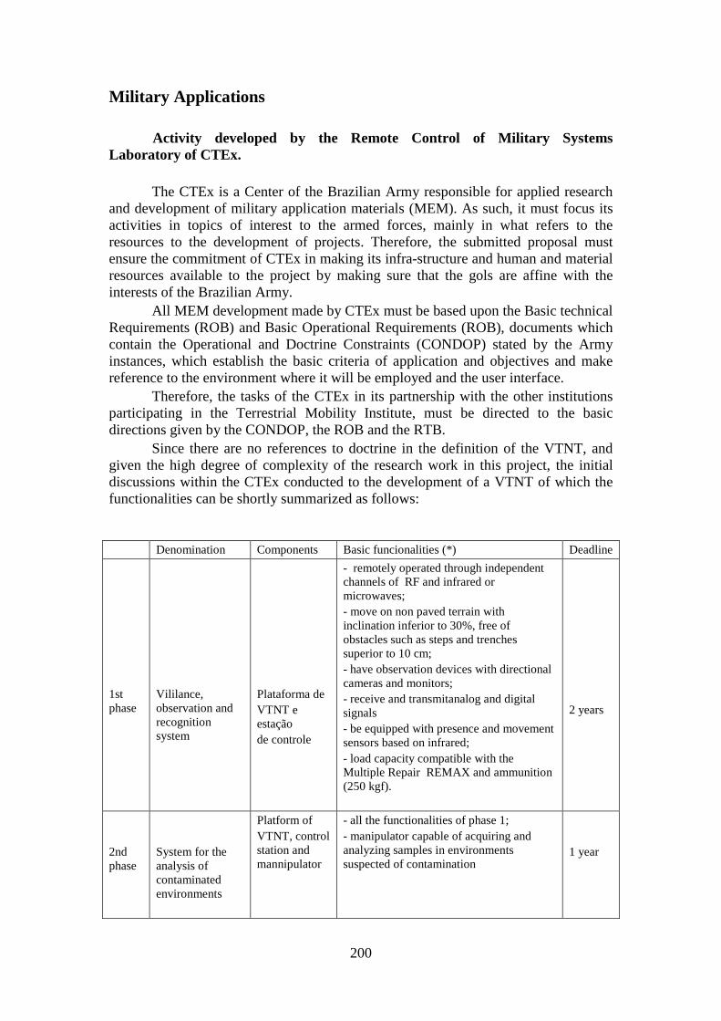
200
Military Applications
Activity developed by the Remote Control of Military Systems Laboratory of CTEx.
The CTEx is a Center of the Brazilian Army responsible for applied research
and development of military application materials (MEM). As such, it must focus its activities in topics of interest to the armed forces, mainly in what refers to the resources to the development of projects. Therefore, the submitted proposal must ensure the commitment of CTEx in making its infra-structure and human and material resources available to the project by making sure that the gols are affine with the interests of the Brazilian Army.
All MEM development made by CTEx must be based upon the Basic technical Requirements (ROB) and Basic Operational Requirements (ROB), documents which contain the Operational and Doctrine Constraints (CONDOP) stated by the Army instances, which establish the basic criteria of application and objectives and make reference to the environment where it will be employed and the user interface.
Therefore, the tasks of the CTEx in its partnership with the other institutions participating in the Terrestrial Mobility Institute, must be directed to the basic directions given by the CONDOP, the ROB and the RTB.
Since there are no references to doctrine in the definition of the VTNT, and given the high degree of complexity of the research work in this project, the initial discussions within the CTEx conducted to the development of a VTNT of which the functionalities can be shortly summarized as follows:
Denomination Components Basic funcionalities (*) Deadline
1st phase
Vililance, observation and recognition system
Plataforma de VTNT e estação de controle
- remotely operated through independent channels of RF and infrared or microwaves; - move on non paved terrain with inclination inferior to 30%, free of obstacles such as steps and trenches superior to 10 cm; - have observation devices with directional cameras and monitors; - receive and transmitanalog and digital signals - be equipped with presence and movement sensors based on infrared; - load capacity compatible with the Multiple Repair REMAX and ammunition (250 kgf).
2 years
2nd phase
System for the analysis of contaminated environments
Platform of VTNT, control station and mannipulator
- all the functionalities of phase 1; - manipulator capable of acquiring and analyzing samples in environments suspected of contamination
1 year
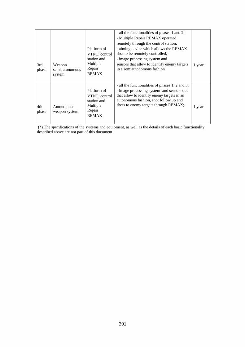
201
3rd phase
Weapon semiautonomous system
Platform of VTNT, control station and Multiple Repair REMAX
- all the functionalities of phases 1 and 2; - Multiple Repair REMAX operated remotely through the control station; - aiming device which allows the REMAX shot to be remotely controlled; - image processing system and sensors that allow to identify enemy targets in a semiautonomous fashion.
1 year
4th phase
Autonomous weapon system
Platform of VTNT, control station and Multiple Repair REMAX
- all the functionalities of phases 1, 2 and 3; - image processing system and sensors que that allow to identify enemy targets in an autonomous fashion, shot follow up and shots to enemy targets through REMAX;
1 year
(*) The specifications of the systems and equipment, as well as the details of each basic functionality described above are not part of this document.
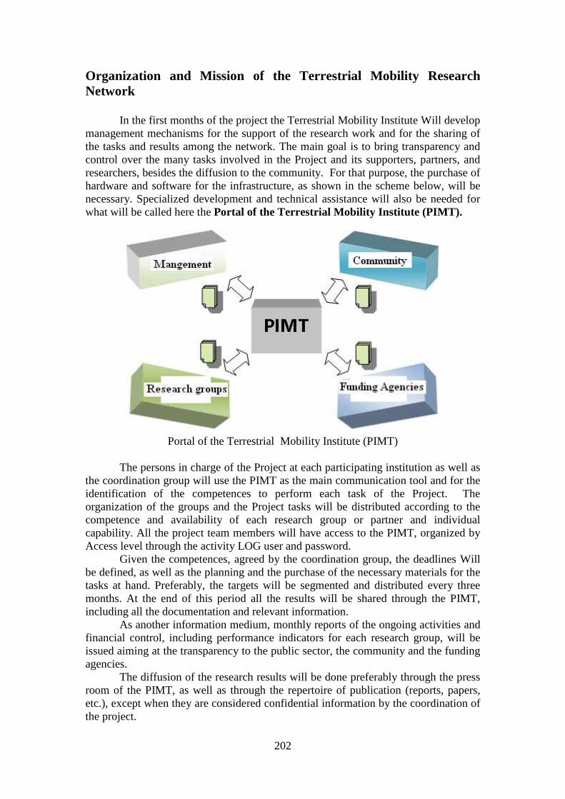
202
Organization and Mission of the Terrestrial Mobility Research Network
In the first months of the project the Terrestrial Mobility Institute Will develop management mechanisms for the support of the research work and for the sharing of the tasks and results among the network. The main goal is to bring transparency and control over the many tasks involved in the Project and its supporters, partners, and researchers, besides the diffusion to the community. For that purpose, the purchase of hardware and software for the infrastructure, as shown in the scheme below, will be necessary. Specialized development and technical assistance will also be needed for what will be called here the Portal of the Terrestrial Mobility Institute (PIMT).
Portal of the Terrestrial Mobility Institute (PIMT)
The persons in charge of the Project at each participating institution as well as the coordination group will use the PIMT as the main communication tool and for the identification of the competences to perform each task of the Project. The organization of the groups and the Project tasks will be distributed according to the competence and availability of each research group or partner and individual capability. All the project team members will have access to the PIMT, organized by Access level through the activity LOG user and password.
Given the competences, agreed by the coordination group, the deadlines Will be defined, as well as the planning and the purchase of the necessary materials for the tasks at hand. Preferably, the targets will be segmented and distributed every three months. At the end of this period all the results will be shared through the PIMT, including all the documentation and relevant information.
As another information medium, monthly reports of the ongoing activities and financial control, including performance indicators for each research group, will be issued aiming at the transparency to the public sector, the community and the funding agencies.
The diffusion of the research results will be done preferably through the press room of the PIMT, as well as through the repertoire of publication (reports, papers, etc.), except when they are considered confidential information by the coordination of the project.
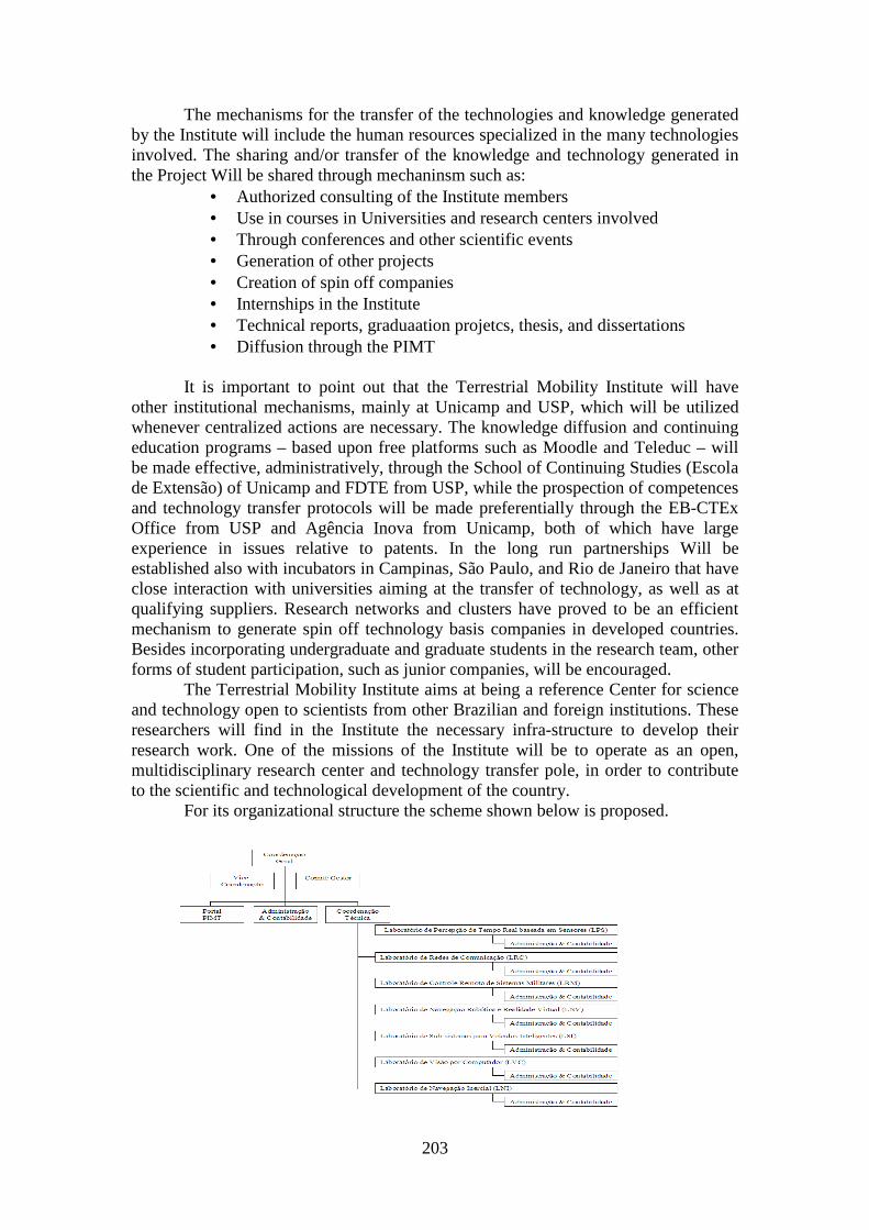
203
The mechanisms for the transfer of the technologies and knowledge generated by the Institute will include the human resources specialized in the many technologies involved. The sharing and/or transfer of the knowledge and technology generated in the Project Will be shared through mechaninsm such as:
• Authorized consulting of the Institute members • Use in courses in Universities and research centers involved • Through conferences and other scientific events • Generation of other projects • Creation of spin off companies • Internships in the Institute • Technical reports, graduaation projetcs, thesis, and dissertations • Diffusion through the PIMT
It is important to point out that the Terrestrial Mobility Institute will have other institutional mechanisms, mainly at Unicamp and USP, which will be utilized whenever centralized actions are necessary. The knowledge diffusion and continuing education programs – based upon free platforms such as Moodle and Teleduc – will be made effective, administratively, through the School of Continuing Studies (Escola de Extensão) of Unicamp and FDTE from USP, while the prospection of competences and technology transfer protocols will be made preferentially through the EB-CTEx Office from USP and Agência Inova from Unicamp, both of which have large experience in issues relative to patents. In the long run partnerships Will be established also with incubators in Campinas, São Paulo, and Rio de Janeiro that have close interaction with universities aiming at the transfer of technology, as well as at qualifying suppliers. Research networks and clusters have proved to be an efficient mechanism to generate spin off technology basis companies in developed countries. Besides incorporating undergraduate and graduate students in the research team, other forms of student participation, such as junior companies, will be encouraged.
The Terrestrial Mobility Institute aims at being a reference Center for science and technology open to scientists from other Brazilian and foreign institutions. These researchers will find in the Institute the necessary infra-structure to develop their research work. One of the missions of the Institute will be to operate as an open, multidisciplinary research center and technology transfer pole, in order to contribute to the scientific and technological development of the country.
For its organizational structure the scheme shown below is proposed.
204
TERRESTRIAL MOBILITY INSTITUTE
• General Coordination
The General Coordination will be responsible for the control and follow up of the evolution metrics of the projects. The strategic decisions will be taken by the General Coordinator after advice from the Management Council composed by the more experienced researchers of the network (total of five researchers). It is suggested that the Council is composed by the General Coordinator, three Coordinators of the Laboratories involved in the three institutions - IME, USP and CTEx – and by the Vice-Coordinator.
Jose Roberto de Franca Arruda – General Coordinator CNPq scholarship for research productivity - level 1A Graduated in Mechanical Engineering from the University of Campinas (Brazil) and Doctor in Applied Mechanics from the University of Paris VI (Pierre et Marie Curie) in 1979. He spent sabbatical leaves with the INSA of Lyon (France) in 1987, with Virginia Tech (USA) in 1991, with the Katholieke Universiteit Leuven (Belgium) in 1996, with the Acoustics Laboratory of the University of Maine (France) in 2004, with the Laboratory of Mechanics and Acoustics of the CNRS in Marseille (France) in 2005, and with the Ecole Centrale de Lyon (2006). He is presently Full Professor of the Department of Computational Mechanics of the University of Campinas (Brazil). Prof. Arruda is a member of the scientific committees of international conferences such as ISMA (Belgium), NOVEM (France), Laser Measurements (Italy), and ICED (Portugal). Over the years, Prof. Arruda has taught and done research in the fields of analytical and experimental structural dynamics, rotordynamics, identification and control of vibration and noise, vibroacoustics, and musical acoustics. More information can be found on scientific data bases such as ISI and Compendex.
Carlos Eduardo Cunasca – Vice-Coordinator Bolsista de Produtividade em Pesquisa do CNPq - Nível 2
Graduated in Electrical Engineering from the University of São Paulo (Brazil) and Doctor in Electrical Engineering from the University of São Paulo (Brazil) in 1993. He is presently Associate Professor of the Department of Computing Engennering of the University of São Paulo (Brazil). Prof. Cugnasca is editor of Revista Brasileira de Agroinformática. Over the years, Prof. Cugnasca has taught and done research in the fields of intelligent instrumentation, control networks, wireless network sensors and pervasive computing. He is member of a standardization committee in ABNT, and member of the ISOBUS Brazil Task Force.
205
IPMT Portal
The Portal will be responsible for the relationship with the users, with the industry, and with society at large. It will be implemented in a gradual way, starting in the first semester of existence of the Institute. Its development will be funded with funds obtained with this project.
• Administrative and Financial Coordinator
He/she will be responsible for the negotiation with suppliers and publis legislation concerning the use of public funds. He/she will be someone with a large experience in management and business administration and will be responsible for the management of the project money and the administrative structure of the Institute. He/she will be hired with project money.
• Technical Coordination
The Technical Coordinator will be responsible for the technical aspects of the Project, acting in agreement with the Coordinators of the different Laboratories involved. He/she should be a researcher with a large experience in research, and will benefit from a scholarship paid with project money. He/she will be appointed by the General Coordinator and approved by the Management Council.
• Laboratory Coordinators
He/she is the researcher responsible for one or more research topics which are detailed in the proposal. He/she will establish execution timetables using research management tools such as the DotProject platform.
Claudio Garcia – Real Time Perception Based Upon Sensors Bolsista de Produtividade em Pesquisa do CNPq - Nível 2 Claudio Garcia is an electric engineer by Polytechnic School of the University of São Paulo - EPUSP, Brazil, 1979. His MSc and PhD degrees were both in Electronic Engineering granted by EPUSP in 1987 and 1992, respectively. He has experience in the areas of process modeling, identification and control. He worked for Foxboro, Taylor, the Brazilian Navy and nowadays he is a professor at EPUSP. His research interests include industrial process control and system modeling and identification. He has a published book in Brazil called “Modeling and simulation of electromechanical systems and industrial processes” and many papers in international congresses and journals.
Clésio Luis Tozzi – Computer Vision
Graduated in Electrical Engineering from Unicamp (1972), Master of Sciences in Electrical Engineering from Unicamp (1975) and Doctor in Electrical Engineering from Unicamp (1979) . Presently Full Professor at Unicamp, he is experienced in in Electrical Engineering with emphasis in computational
206
engineering mainly in the fields of Computer Architectures, Digital Circuits and Computer Graphics. Carlos Eduardo Cunasca – Communication Networks Bolsista de Produtividade em Pesquisa do CNPq - Nível 2
Jorge Audrin Morgado de Góis – Inertial Navigation
Graduated in Mechanical Engineering from IME and Doctor from the Universitat Duisburg-Essen, UNIDUE, Germany. Captain of the Military Engineers Corps, having served with the Centro Tecnológico do Exercito. Presently he is a Professor with IME and a specialist in the fields of mechatronics, dinamics and data fusion.
Juan Francisco Camino dos Santos – Robotic Navigation and Virtual Reality
Graduated in Mechanical Engineering from Universidade Federal da Paraíba (1994), M.Sc. Mechanical Engineering from Unicamp (1997), Ph.D. in Aeroespace Engineering from the University of Califórnia at San Diego (2003) and post-doctor with Universidade Estadual de Campinas (2006) and Katholieke Universiteit Leuven (2007). Currently he is Assistant Professor at Universidade Estadual de Campinas. He is experienced in Mechanical Engineering with emphasis in Mechanical System Control, mainly in the fields of convex optimization, semidefinite optimization, active noise and vibration control, control of time0varying systems .
Pablo Siqueira Meirelles – Subsystems for Intelligent Vehicles
Graduated in Mechanical Engineering from the University of Campinas (Brazil) in 1985, Master in Mechanical Engineering at Unicamp in 1988 and Doctor in Mechanical Engineering from the Ecole Centrale de Lyon (France) in 1995. He spent sabbatical leaves with the TU Darmstadt (Germany) in 2004 and 2006. Currently Professor of the Department of Computational Mechanics of the University of Campinas (Brazil). Consultant "Ad Hoc" of the IEEE Transactions on Power Electronics, Structural Engineering and Mechanics magazine and the Brazilian magazine of Mechanical Sciences. Prof. Pablo done research in the fields of analytical and experimental structural dynamics, system identification and control, vibrations and Vehicle Dynamics.
Victor Santoro Santiago – Remote Control of Military Systems
Graduated in Mechanical Engineering from Military Engineering Institute (Brazil) in 1997 and Master in Mechanical Engineering from Military Engineering Institute (Brazil) in 2003. He has been Program Manager in Army Research Center and has been a PhD student in Rio de Janeiro Federal University, where he is working with Vortex Methods in Computatitonal Fluid Mechanics.
207
Besides the researchers previously cited, the following researchers also participate in the Terrestrial Mobility Institute:
Alberto Luiz Serpa received the Mechanical Engineering degree from the University of Campinas - UNICAMP (1989), received the Master degree in Mechanical Engineering by UNICAMP (1991) and the Ph.D. in Mechanical Engineering by UNICAMP (1996). In the period of December 1990 to December 2001, he worked for Clark Equipments Ltd, which currently belongs to Eaton Corporation. In December 2001, he left private sector and began working as a full time professor in UNICAMP. He has experience in Mechanical Engineering, with emphasis on computational and structural mechanics, investigating mainly the following topics: control of mechanical systems, system optimization, non-linear modeling, non-linear programming, robust control and control of flexible structures and finite element method.
Alberto Gaspar Guimarães is a Telecomunications Engineer graduated from IME, Máster of Sciences in Signal Processing from IME and Doctor in Tecommunication Systems by PUC-RJ. He is a specialist in Signal Processing and Telecommunication Systems. He is a Professor at IME since 2004.
Antonio Carlos Castañon Vieira graduated in Electronic Engineering from the Instituto Militar de Engenharia (1989), M.Sc. in Electrical Engineeering from the Universidade Federal do Rio de Janeiro (1999), Doctor in Electrical Engineeering from the Universidade Federal do Rio de Janeiro (2005). Presently He is Project Manager of the Centro Tecnológico do Exército, Professor of the Universidade Estácio de Sá and Judicial expert of the Tribunal Regional do Trabalho 1a Região (RJ). He is experienced in Electrical Engineeering with emphasis on Telecommunications, mainly in safety applications, Criptography, Hardware circuit description.
Arthur de Miranda Neto is a Doctor in Mechanical Engineering from the University of Campinas (Unicamp). M. SC. 2007 in Mechanical Engineering from Unicamp in Robot Navigation Based On monovision. He is experienced in the development of software for robotics, distributed systems (Multithreading), Computational Vision. 1st Lieutenant R/2 Brazilian Army. Five years experience as University Professor in the field of Computer Sciences. Last activity in the public sector was Technology Annalist at Dataprev-RJ. He is currently a graduate student with the Department of Computational Mechanics at Unicamp and has a CNPq PhD scholarship.
Danilo Habermann is an electric engineer by Military Engineering Institute - IME, Brazil, 2005. He is a Brazilian Army official and master student of Polytechnic School of the University of São Paulo – EPUSP.
Douglas Eduardo Zampieri, graduated in Mechanical Engineering from the University of Campinas - Unicamp, Brazil (1972) and Doktor-Ingenieur from the University of Stuttgart, Germany (1981). Spent sabbatical leaves with the Applied Sciences University Regensburg, Germany (1992), with the University of Darmstadt, Germany (2003). Dean of the Mechanical
208
Engineering Faculty of Unicamp (1994-1998), Executive Director of the Transfer Technology Office of Unicamp (1998-2003). Retired in 2004, presently is Visitor Professor of the Computational Mechanics of Unicamp. Major research areas: control and vibration; mechatronics and robotics.
Geraldo Gurgel Filho graduated in Electrical Engineering form the Instituto Militar de Engenharia (1983) and hás a Máster degree in Mechanical Egineering from the Pontifícia Universidade Católica of Rio de Janeiro (1999). Currently he is an army official – engineer of the Centro Tecnológico do Exército and teaches at the Universidade Estácio de Sá. He is experienced in Electrical Engineering with emphasis in Industrial Electronics, Electronic Systems and Controls, mainly in gyroscopic, inertial sensors, rotor dynamics and fog.
Janito Vaqueiro Ferreira graduated in Mechanical Engineering from Unicamp (1983), Máster of Sciences in Mechanical Engineering from Unicamp (1989) and Ph.D. in Dynamics from the Imperial College Of Science, Technology, and Medicine (1998) . He is currently Assistant Professor of Unicamp. He is experienced in Mechanical Engineering with emphasis in Solid Mechanics, mainly in the fields of: Coupling of structures and Nonlinear analysis.
José Maria Campos dos Santos: graduated in Mechanical Engineer at Universidade Estadual do Maranhão (1977), M. Sc. degree in Mechanical Engineer at Universidade de São Paulo (1983), PhD in Mechanical Engineer at Universidade Estadual de Campinas (1993), post-doctorate at University of Houston (1996) and post-doctorate at Institute of Sound and Vibration Research - University of Southampton (2006). Today is Associated Professor at Universidade Estadual de Campinas, reviewer of Shock and Vibration e and Journal of the Brazilian Society of Mechanical Sciences and Engineering. Experienced in the area of Solid Mechanics in Mechanical Engineer.Luciano Luporini Menegaldo is a Mechanical Engineer from Unicamp, Master of Sciences in Mechanical Engineering form Unicamp and Doctor in Mechanical Engineering from USP. He is presently Associate Professor at IME. He is experienced in the fields of mechanics, robotics and control of mechanical systems.
Paulo Roberto Rocha Aguiar graduated in Mechanical Engineering from the Instituto Militar de Engenharia (1993), Master graduated in Mechanical Engineering from the Pontifícia Universidade Católica do Rio de Janeiro (1997) and Doctor graduated in Mechanical Engineering from the Pontifícia Universidade Católica do Rio de Janeiro (2002). Currently teaches at the Universidade Cândido Mendes and is a researcher of the Centro Tecnológico do Exército. He is experienced in Mechanical Engineering with emphasis on Solid Mechanics, mainly with Suspended structures, Vehicular comfort, Control and Dynamics.
Paulo Fernando Ferreira Rosa graduated in Electrical Engineering form the Universidade Federal de Pernambuco (1986), Master in Computer Sciences and Systems Engineering (M.Eng.) from Kyushu Institute of Technology -
209
Japan (1994) and Doctor in Information Engineering (PhD) from Niigata University - Japan (1997). Was a post-doc scholar (CNPq) with the Depto. de Ciência da Computação of UFF, 1997-98 and visiting researcher with IME, 1999. He was the coordinator of the graduate school of Computation and Systems of IME, 2004-07. Currently he is an Associate Professor of the Instituto Militar de Engenharia and vice-coordinator of the graduate school. In 2007 he chaired the XXVII Congresso da Sociedade Brasileira de Computação. He is experienced in Robotics and Automation, acting mainly in autonomous robots, flexible manipulators, domotics – intelligent houses and flying unmanned vehicles. He is currently post-doc at the Dept. ofe Cybernetics at Niigata University (scholarship JASSO).
ANEXOS
CRONOGRAMAS E PLANILHAS
ORÇAMENTÁRIAS

CRONOGRAMAS
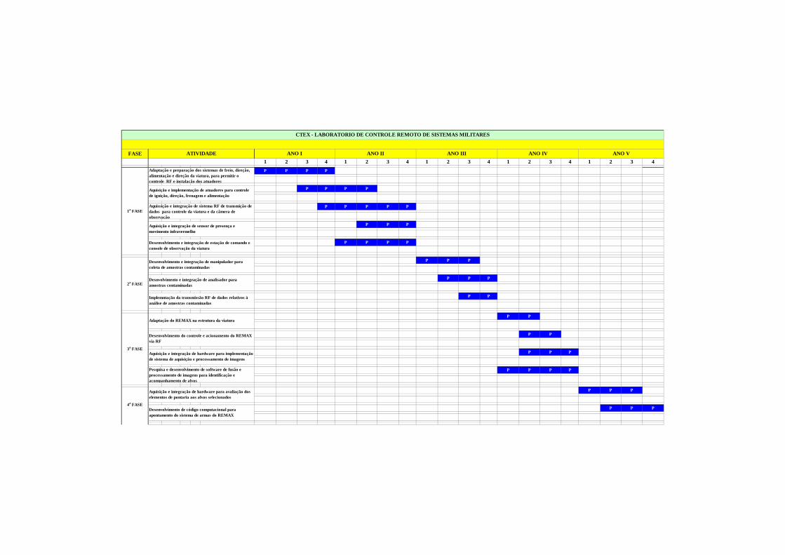
FASE
1 2 3 4 1 2 3 4 1 2 3 4 1 2 3 4 1 2 3 4
P P P P E E E E E E E E E E E P
E E E E E E E E E E E E E E E
P P P P P P P P P P P PE E E E E
E E E E E E E E E E
P P P P P
P P P P P P P
E E E E E
P P P P
P P P
P P P
P P
P P
P P
P P P
P P P P
P P P
P P P
ANO II ANO IIIANO I
2a FASE
Implemntação da transmissão RF de dados relativos à análise de amostras contaminadas
Desenvolvimento e integração de manipulador para coleta de amostras contaminadas
ATIVIDADE
Desenvolvimento e integração de estação de comando e console de observação da viatura
3a FASE
4a FASEDesenvolvimento de código computacional para apontamento do sistema de armas do REMAX
Adaptação do REMAX na estrutura da viatura
Aquisição e integração de hardware para avaliação dos elementos de pontaria aos alvos selecionados
Pesquisa e desenvolvimento de software de fusão e processamento de imagens para identificação e acompanhamento de alvos
Desenvolvimento do controle e acionamento do REMAX via RF
Aquisição e integração de hardware para implementação de sistema de aquisição e processamento de imagens
Desnvolvimento e integração de analisador para amostras contaminadas
Aquisição e integração de sensor de presença e movimento infravermelho
CTEX - LABORATORIO DE CONTROLE REMOTO DE SISTEMAS M ILITARES
Aquisição e implementação de atuadores para controle de ignição, direção, frenagem e alimentação
ANO IV ANO V
1a FASEAquissição e integração de sistema RF de transmição de dados para controle da viatura e da câmera de observação
Adaptação e preparação dos sistemas de freio, direção, alimentação e direção da viatura, para permitir o controle RF e instalação dos atuadores
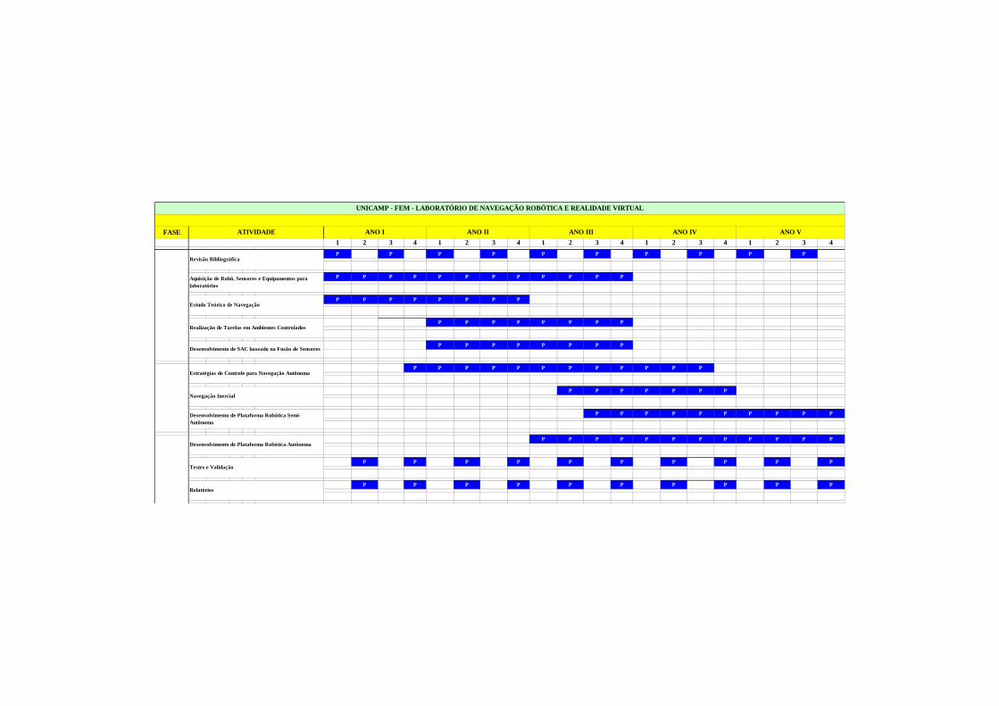
FASE
1 2 3 4 1 2 3 4 1 2 3 4 1 2 3 4 1 2 3 4
P P P P P P P P P P P P P P P P P P P P
E E E E E E E E E E E E E E E
P P P P P P P P P P P P P P P PE E E E E
E E E E E E E E E E
P P P P P P P P
P P P P P P P P P P P P
E E E E E
P P P P P P P P
P P P P P P P P P P P P
P P P P P P P
P P P P P P P P P P
P P P P P P P P P P P P
P P P P P P P P P P P
P P P P P P P P P P P
ANO II ANO IIIANO I
Desenvolvimento de Plataforma Robótica Semi-Autônoma
Estratégias de Controle para Navegação Autônoma
ATIVIDADE
Desenvolvimento de SAC baseado na Fusão de Sensores
Desenvolvimento de Plataforma Robótica Autônoma
Testes e Validação
Relatórios
Navegação Inercial
Realização de Tarefas em Ambientes Controlados
UNICAMP - FEM - LABORATÓRIO DE NAVEGAÇÃO ROBÓTICA E REALIDADE VIRTUAL
Aquisição de Robô, Sensores e Equipamentos para laboratórios
ANO IV ANO V
Estudo Teórico de Navegação
Revisão Bibliográfica
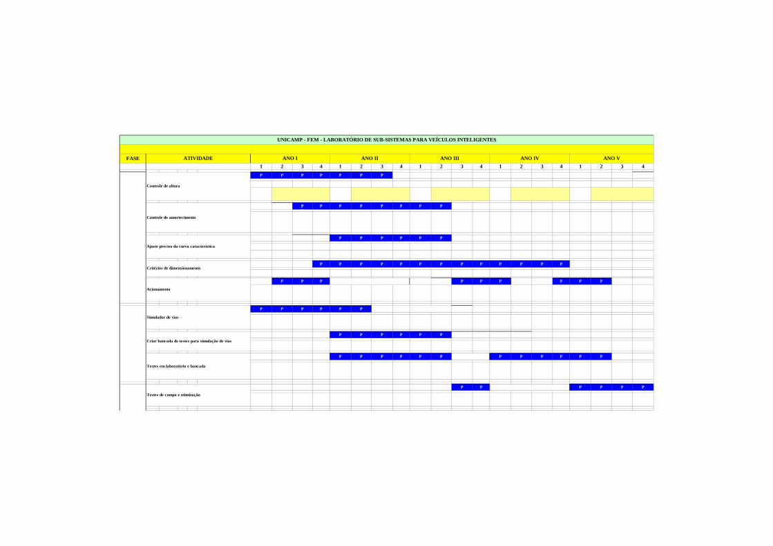
FASE
1 2 3 4 1 2 3 4 1 2 3 4 1 2 3 4 1 2 3 4
P P P P P P P E E E E E E E E E P
E E E E E E E E E E E E E E E
P P P P P P P P P P P P P PE E E E E
E E E E E E E E E E
P P P P P P P P
P P P P P P P P P P P P P P
E E E E E
P P P P P P P P P P
P P P P P P P
P P P P P P P P P P
P P P P P P P P P P P P
P P P P P P
ANO II ANO IIIANO I
Testes em laboratório e bancada
Simulador de vias
ATIVIDADE
Acionamento
Testes de campo e otimização
Criar bancada de testes para simulação de vias
Critérios de dimensionamento
UNICAMP - FEM - LABORATÓRIO DE SUB-SISTEMAS PARA VE ÍCULOS INTELIGENTES
Controle de amortecimento
ANO IV ANO V
Ajuste preciso da curva característica
Controle de altura
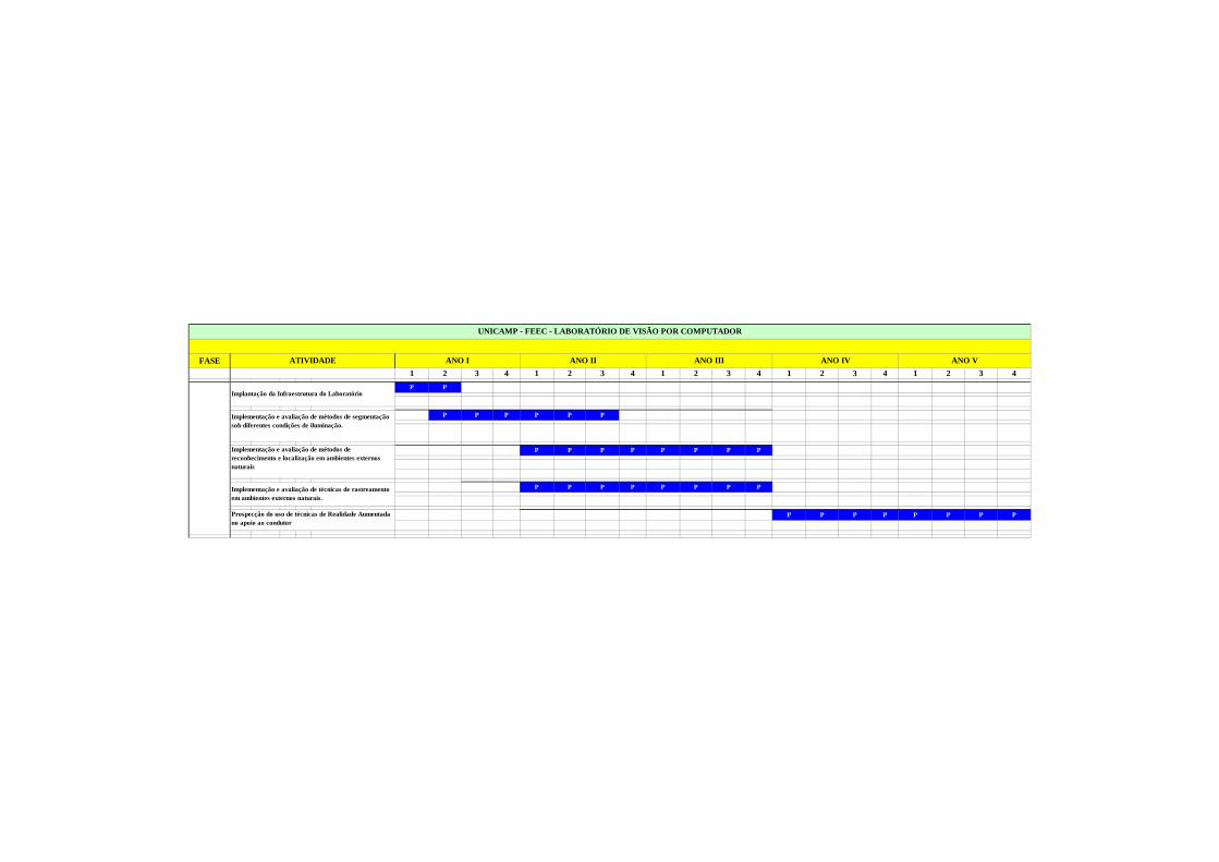
FASE
1 2 3 4 1 2 3 4 1 2 3 4 1 2 3 4 1 2 3 4
P P
E E E E E E E E E E E E E E E
P P P P P PE E E E E
E E E E E E E E E E
P P P P P P P P
P P P P P P P P P P
E E E E E
P P P P P P P P
UNICAMP - FEEC - LABORATÓRIO DE VISÃO POR COMPUTADO R
Implementação e avaliação de métodos de segmentação sob diferentes condições de iluminação.
ANO IV ANO V
Implementação e avaliação de métodos de reconhecimento e localização em ambientes externos naturais
Implantação da Infraestrutura do Laboratório
Implementação e avaliação de técnicas de rastreamento em ambientes externos naturais.
ANO II ANO IIIANO IATIVIDADE
Prospecção do uso de técnicas de Realidade Aumentada no apoio ao condutor
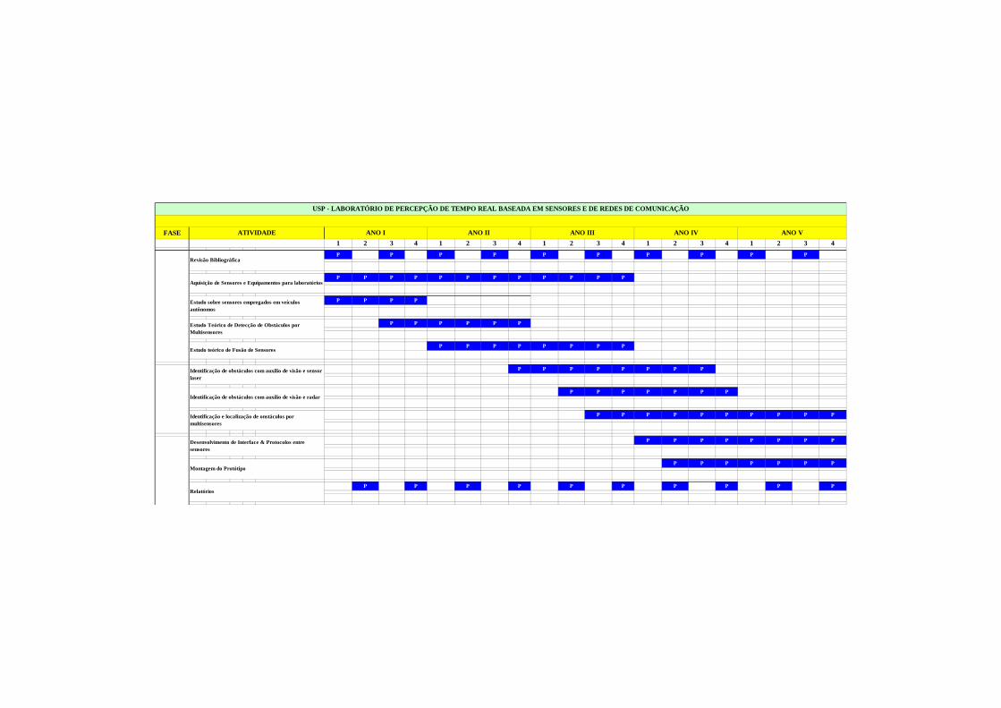
FASE
1 2 3 4 1 2 3 4 1 2 3 4 1 2 3 4 1 2 3 4
P P P P P P P P P P P P P P P P P P P P
E E E E E E E E E E E E E E E
P P P P P P P P P P P P P P P PE E E E E
E E E E E E E E E E
P P P P P P P P
P P P P P P P P P
E E E E E
P P P P P P P P
P P P P P P P P
P P P P P P P
P P P P P P P P P P
P P P P P P P P
P P P P P P P
P P P P P P P P P P P
USP - LABORATÓRIO DE PERCEPÇÃO DE TEMPO REAL BASEAD A EM SENSORES E DE REDES DE COMUNICAÇÃO
Aquisição de Sensores e Equipamentos para laboratórios
ANO IV ANO V
Estudo sobre sensores empregados em veículos autônomos
Revisão Bibliográfica
Estudo Teórico de Detecção de Obstáculos por Multisensores
Relatórios
Identificação de obstáculos com auxilio de visão e radar
Desenvolvimento de Interface & Protocolos entre sensores
Montagem do Protótipo
ANO II ANO IIIANO I
Identificação e localização de onstáculos por multisensores
Identificação de obstáculos com auxilio de visão e sensor laser
ATIVIDADE
Estudo teórico de Fusão de Sensores
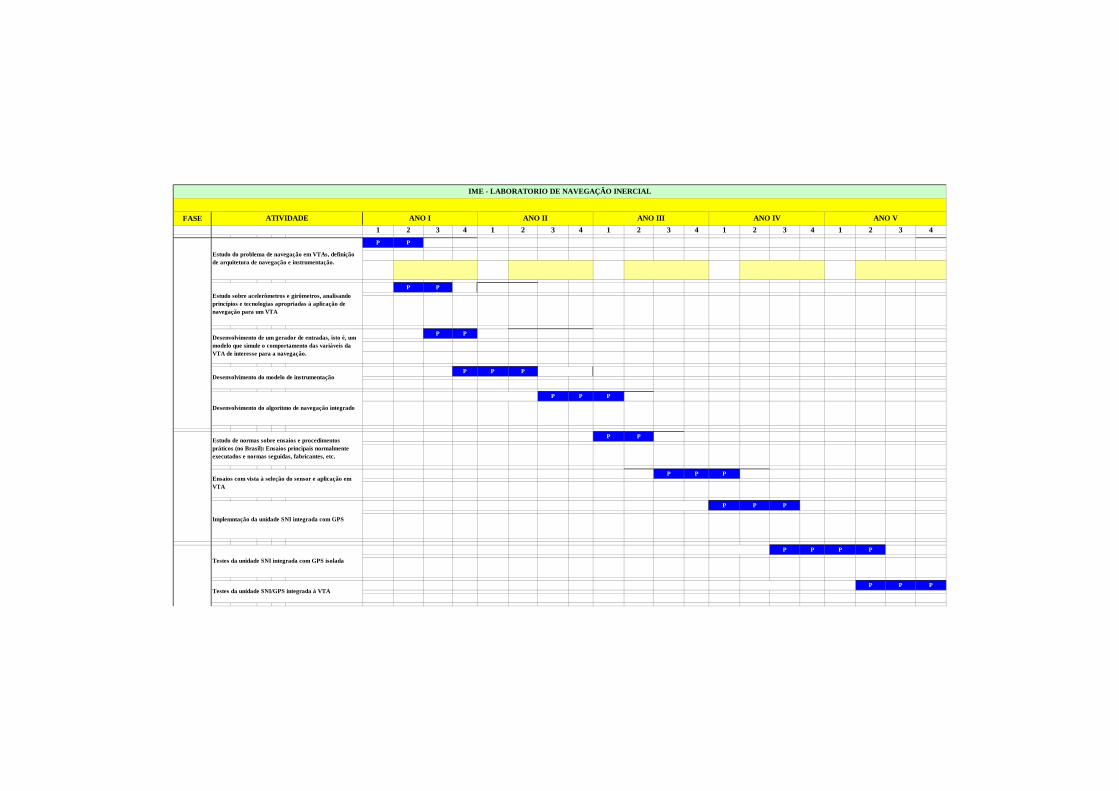
FASE
1 2 3 4 1 2 3 4 1 2 3 4 1 2 3 4 1 2 3 4
P P P E E E E E E E E E E E P
E E E E E E E E E E E E E E E
P P P P P P P P P P PE E E E E
E E E E E E E E E E
P P P P P
P P P P P P
E E E E E
P P P P
P P P
P P P P P
P P P
P P P P
P P P
IME - LABORATORIO DE NAVEGAÇÃO INERCIAL
Estudo sobre acelerômetros e girômetros, analisando princípios e tecnologias apropriadas à aplicação de navegação para um VTA
ANO IV ANO V
Desenvolvimento de um gerador de entradas, isto é, um modelo que simule o comportamento das variáveis da VTA de interesse para a navegação.
Estudo do problema de navegação em VTAs, definição de arquitetura de navegação e instrumentação.
Desenvolvimento do modelo de instrumentação
Ensaios com vista à seleção do sensor e aplicação em VTA
Testes da unidade SNI integrada com GPS isolada
Testes da unidade SNI/GPS integrada à VTA
ANO II ANO IIIANO I
Implemntação da unidade SNI integrada com GPS
Estudo de normas sobre ensaios e procedimentos práticos (no Brasil): Ensaios principais normalmente executados e normas seguidas, fabricantes, etc.
ATIVIDADE
Desenvolvimento do algoritmo de navegação integrado
PLANILHAS ORÇAMENTÁRIAS
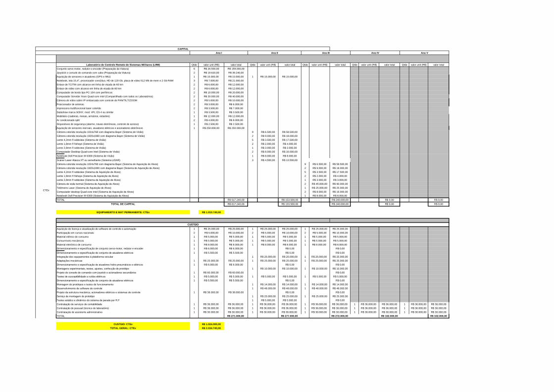
Qtde valor unit (R$) valor total Qtde valor unit (R$) valor total Qtde valor unit (R$) valor total Qtde valor unit (R$) valor total Qtde valor unit (R$) valor total
Conjunto servo motor, redutor e encoder (Preparação da Viatura) 6 R$ 26.500,00 R$ 159.000,00
Jjoystick e console de comando com cabo (Preparação da Viatura) 2 R$ 19.620,00 R$ 39.240,00
Aquisição de sensores e atuadores (GPS e IMU) 1 R$ 15.000,00 R$ 15.000,00 1 R$ 15.000,00 R$ 15.000,00
Notebook, tela 15,4", processador core2duo, HD de 120 Gb, placa de vídeo 512 Mb de mem e 2 Gb RAM 3 R$ 7.000,00 R$ 21.000,00
Enlace de TC/TM com alcance em linha de visada de 60 km 2 R$ 6.000,00 R$ 12.000,00
Enlace de vídeo com alcance em linha de visada de 60 km 2 R$ 6.000,00 R$ 12.000,00
Computador de bordo tipo PC-104 com periféricos 2 R$ 10.000,00 R$ 20.000,00
Computador Servidor Xeon Quad-core intel (Compartilhado com todos os Laboratórios) 2 R$ 20.000,00 R$ 40.000,00
Câmera de vídeo sobre IP embarcada com controle de PAN/TILT/ZOOM 2 R$ 5.000,00 R$ 10.000,00
Posicionador de antenas 2 R$ 3.000,00 R$ 6.000,00
Impressora multifuncional laser colorida 2 R$ 3.500,00 R$ 7.000,00
Datashow marca SONY, mod. VPL ES-4 ou similar 1 R$ 3.500,00 R$ 3.500,00
Mobiliário (cadeiras, mesas, armários, estantes) 1 R$ 12.000,00 R$ 12.000,00
Ar condicionado split 2 R$ 4.000,00 R$ 8.000,00
Dispositivos de segurança (alarme, travas eletrônicas, controle de acesso) 1 R$ 2.500,00 R$ 2.500,00
Aquisição de sensores inerciais, atuadores elétricos e acionadores eletrônicos 1 R$ 250.000,00 R$ 250.000,00
Câmera colorida resolução 1024x768 com diagrama Bayer (Sistema de Visão) 9 R$ 6.500,00 R$ 58.500,00
Câmera colorida resolução 1920x1080 com diagrama Bayer (Sistema de Visão) 2 R$ 9.000,00 R$ 18.000,00
Lente 4,2mm fl wideview (Sistema de Visão) 5 R$ 3.500,00 R$ 17.500,00
Lente 1,8mm fl fisheye (Sistema de Visão) 2 R$ 2.000,00 R$ 4.000,00
Lente 2,8mm fl wideview (Sistema de Visão) 1 R$ 3.000,00 R$ 3.000,00
Computador Desktop Quad-core intel (Sistema de Visão) 2 R$ 8.000,00 R$ 16.000,00
Notebook Dell Precision M 6300 (Sistema de Visão) 1 R$ 8.000,00 R$ 8.000,00
Scaner Laser Alasca XT ou semelhante (Sistema LIDAR) 3 R$ 4.500,00 R$ 13.500,00
Câmera colorida resolução 1024x768 com diagrama Bayer (Sistema de Aquisição de Alvos) 9 R$ 6.500,00 R$ 58.500,00
Câmera colorida resolução 1920x1080 com diagrama Bayer (Sistema de Aquisição de Alvos) 2 R$ 9.000,00 R$ 18.000,00
Lente 4,2mm fl wideview (Sistema de Aquisição de Alvos) 5 R$ 3.500,00 R$ 17.500,00
Lente 1,8mm fl fisheye (Sistema de Aquisição de Alvos) 2 R$ 2.000,00 R$ 4.000,00
Lente 2,8mm fl wideview (Sistema de Aquisição de Alvos) 1 R$ 3.000,00 R$ 3.000,00
Câmera de visão termal (Sistema de Aquisição de Alvos) 2 R$ 45.000,00 R$ 90.000,00
Telêmetro Laser (Sistema de Aquisição de Alvos) 1 R$ 25.000,00 R$ 25.000,00
Computador desktop Quad-core intel (Sistema de Aquisição de Alvos) 2 R$ 8.000,00 R$ 16.000,00
Notebook Dell Precision M 6300 (Sistema de Aquisição de Alvos) 1 R$ 8.000,00 R$ 8.000,00
TOTAL R$ 617.240,00 R$ 153.500,00 R$ 240.000,00 R$ 0,00 R$ 0,00
R$ 617.240,00 R$ 153.500,00 R$ 240.000,00 R$ 0,00 R$ 0,00
R$ 1.010.740,00
1 R$ 25.000,00 R$ 25.000,00 1 R$ 25.000,00 R$ 25.000,00 1 R$ 25.000,00 R$ 25.000,00
2 R$ 5.000,00 R$ 10.000,00 2 R$ 5.000,00 R$ 10.000,00 2 R$ 5.000,00 R$ 10.000,00
Material elétrico de consumo 1 R$ 5.000,00 R$ 5.000,00 1 R$ 5.000,00 R$ 5.000,00 1 R$ 5.000,00 R$ 5.000,00
Consumíveis mecânicos 1 R$ 5.000,00 R$ 5.000,00 1 R$ 5.000,00 R$ 5.000,00 1 R$ 5.000,00 R$ 5.000,00
Material eletrônico de consumo 1 R$ 8.000,00 R$ 8.000,00 1 R$ 8.000,00 R$ 8.000,00 1 R$ 8.000,00 R$ 8.000,00
Dimensionamento e especificação de conjunto servo-motor, redutor e encoder 1 R$ 6.000,00 R$ 6.000,00 R$ 0,00 R$ 0,00
Dimensionamento e especificação de conjunto de atuadores elétricos 1 R$ 5.500,00 R$ 5.500,00 R$ 0,00 R$ 0,00
Integração dos equipamentos à plataforma veicular 1 R$ 25.000,00 R$ 25.000,00 1 R$ 25.000,00 R$ 25.000,00
Adaptações mecânicas 1 R$ 25.000,00 R$ 25.000,00 1 R$ 25.000,00 R$ 25.000,00 1 R$ 25.000,00 R$ 25.000,00
Dimensionamento e especificação de atuadores hidro-pneumáticos e elétricos 1 R$ 6.000,00 R$ 6.000,00 R$ 0,00 R$ 0,00
Montagens experimentais, testes, ajustes, confecção de protótipo 1 R$ 10.000,00 R$ 10.000,00 1 R$ 10.000,00 R$ 10.000,00
Projeto do console de comando com joystick e acionadores secundários 1 R$ 60.000,00 R$ 60.000,00 R$ 0,00
Testes de susceptibilidade a ruídos elétricos 1 R$ 5.000,00 R$ 5.000,00 1 R$ 5.000,00 R$ 5.000,00 1 R$ 5.000,00 R$ 5.000,00
Dimensionamento e especificação de conjunto de atuadores elétricos 1 R$ 5.500,00 R$ 5.500,00 R$ 0,00 R$ 0,00
Montagem de protótipos e testes de funcionamento 1 R$ 14.000,00 R$ 14.000,00 1 R$ 14.000,00 R$ 14.000,00
Desenvolvimento de software de controle 1 R$ 48.000,00 R$ 48.000,00 1 R$ 48.000,00 R$ 48.000,00
Projeto da estrutura mecânica, acionadores elétricos e sistemas de controle 1 R$ 38.000,00 R$ 38.000,00 R$ 0,00 R$ 0,00
Serviço de montagem do prototipo 1 R$ 25.000,00 R$ 25.000,00 1 R$ 25.000,00 R$ 25.000,00
Testes estático e dinâmico do sistema de parada por R.F 1 R$ 5.000,00 R$ 5.000,00 R$ 0,00
Contratação de serviços de contabilidade 1 R$ 36.000,00 R$ 36.000,00 1 R$ 36.000,00 R$ 36.000,00 1 R$ 36.000,00 R$ 36.000,00 1 R$ 36.000,00 R$ 36.000,00 1 R$ 36.000,00 R$ 36.000,00
Contratação de pessoal (técnico de laboratório) 1 R$ 36.000,00 R$ 36.000,00 1 R$ 36.000,00 R$ 36.000,00 1 R$ 36.000,00 R$ 36.000,00 1 R$ 36.000,00 R$ 36.000,00 1 R$ 36.000,00 R$ 36.000,00
Contrtatação de assistente administrativo 1 R$ 30.000,00 R$ 30.000,00 1 R$ 30.000,00 R$ 30.000,00 1 R$ 30.000,00 R$ 30.000,00 1 R$ 30.000,00 R$ 30.000,00 1 R$ 30.000,00 R$ 30.000,00
TOTAL R$ 271.000,00 R$ 277.000,00 R$ 272.000,00 R$ 102.000,00 R$ 102.000,00
R$ 1.024.000,00
R$ 2.034.740,00
Ano IVAno III
CAPITAL
Ano V
CTEx
Laboratório de Controle Remoto de Sistemas Militare s (LRM)
TOTAL DE CAPITAL
CUSTEIO
Ano I Ano II
EQUIPAMENTO E MAT PERMANENTE: CTEx
CUSTEIO: CTEx
TOTAL GERAL: CTEx
Aquisição de licença e atualização de software de controle e automação
Participação em cursos nacionais
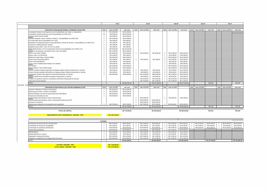
Qtde valor unit (R$) valor total Qtde valor unit (R$) valor total Qtde valor unit (R$) valor total Qtde valor unit (R$) valor total Qtde valor unit (R$) valor total
Computador Servidor Xeon Quad-core intel (Compartilhado com todos os Laboratórios) 2 R$ 20.000,00 R$ 40.000,00
Computador Desktop Quad-core intel (Compartilhado com FEM-LSVI) 20 R$ 8.000,00 R$ 160.000,00
Notebook Dell Precision M 6300 2 R$ 8.000,00 R$ 16.000,00
Mobiliário (cadeiras, mesas, armários, estantes) - (Compartilhado com FEM-LSVI) 2 R$ 12.000,00 R$ 24.000,00
Ar condicionado split (Compartilhado com LSVI) 2 R$ 4.000,00 R$ 8.000,00
Dispositivos de segurança (alarme, travas eletrônicas, controle de acesso) - (Compartilhado com FEM-LSVI) 1 R$ 2.500,00 R$ 2.500,00
Impressora multifuncional laser colorida 2 R$ 3.500,00 R$ 7.000,00
Datashow marca SONY, mod. VPL ES-4 ou similar 1 R$ 3.500,00 R$ 3.500,00
Mobile Robot Pioneer 3 AT & Componentes-Sensores (Compartilhado com a FEEC-LVC) 2 R$ 55.000,00 R$ 110.000,00
Módulo de comunicação e simulação sensor Laser sick Matlab 1 R$ 15.000,00 R$ 15.000,00
Sensor Laser SICK LMS200 1 R$ 18.000,00 R$ 18.000,00 1 R$ 18.000,00 R$ 18.000,00 2 R$ 18.000,00 R$ 36.000,00
Sensor Laser LLD-150-RS232 1 R$ 3.500,00 R$ 3.500,00 1 R$ 3.500,00 R$ 3.500,00
Módulo de Fusão Radar e Câmera Delphi 1 R$ 25.000,00 R$ 25.000,00 1 R$ 25.000,00 R$ 25.000,00
Sensor Sonar Sense MIC130DTC 1 R$ 2.500,00 R$ 2.500,00 1 R$ 2.500,00 R$ 2.500,00 2 R$ 2.500,00 R$ 5.000,00
Sensor Sonar MIC600DTC 1 R$ 9.000,00 R$ 9.000,00 1 R$ 9.000,00 R$ 9.000,00
Sensor Laser Omnidirecional Velodyne com software 1 R$ 8.000,00 R$ 8.000,00 1 R$ 8.000,00 R$ 8.000,00
GPS System 1 R$ 20.000,00 R$ 20.000,00 1 R$ 20.000,00 R$ 20.000,00
Sensor Navtech 77GHz FMCW Radar 1 R$ 18.000,00 R$ 18.000,00 1 R$ 18.000,00 R$ 18.000,00
Câmera colorida resolução 1024x768 com diagrama Bayer (Sistema Embarcado no Veículo) 1 R$ 6.500,00 R$ 6.500,00 1 R$ 6.500,00 R$ 6.500,00 2 R$ 6.500,00 R$ 13.000,00
Câmera colorida resolução 1920x1080 com diagrama Bayer (Sistema Embarcado no Veículo) 1 R$ 9.000,00 R$ 9.000,00 1 R$ 9.000,00 R$ 9.000,00 2 R$ 9.000,00 R$ 18.000,00
Computador Servidor Xeon Quad-core intel (Grid Embarcado no Veículo) 2 R$ 20.000,00 R$ 40.000,00 3 R$ 20.000,00 R$ 60.000,00 2 R$ 20.000,00 R$ 40.000,00
Notebook Dell Precision M 6300 (Simulações Embarcadas no Veículo) 1 R$ 8.000,00 R$ 8.000,00 1 R$ 8.000,00 R$ 8.000,00
Conjunto de atuadores elétricos e acionadores eletrônicos (Preparação da Veículo) 1 R$ 18.920,00 R$ 18.920,00 1 R$ 18.920,00 R$ 18.920,00
Viatura tipo Fora de Estrada 1 R$ 75.000,00 R$ 75.000,00 1 R$ 75.000,00 R$ 75.000,00
TOTAL R$ 505.500,00 R$ 197.920,00 R$ 297.420,00 R$ 0,00 R$ 0,00
Qtde valor unit (R$) valor total Qtde valor unit (R$) valor total Qtde valor unit (R$) Qtde valor unit (R$) Qtde valor unit (R$) valor total
Atuadores Hidráulicos & Placas Controladoras 4 R$ 30.000,00 R$ 120.000,00
Sistemas para montar o Veículo no Simulador 4 R$ 10.000,00 R$ 40.000,00
Bomba Hidráulica com fluxo de aproximadamente 350L/Minuto 1 R$ 50.000,00 R$ 50.000,00
Programa de Simulador de Vias 1 R$ 20.000,00 R$ 20.000,00
Instrumentação para Monitorar Testes: Extensometria 1 R$ 60.000,00 1 R$ 8.000,00 R$ 8.000,00
Instrumentação para Monitorar Testes: Aceleração/Força/Pressão (ICP) 1 R$ 90.000,00 R$ 90.000,00
Sensores e Acessórios 1 R$ 60.000,00 R$ 60.000,00
Material para confecção de componentes das suspensões 1 R$ 37.500,00 R$ 37.500,00 1 R$ 75.000,00 R$ 75.000,00 1 R$ 90.000,00 R$ 90.000,00
TOTAL R$ 267.500,00 R$ 225.000,00 R$ 98.000,00 R$ 0,00 R$ 0,00
R$ 773.000,00 R$ 422.920,00 R$ 395.420,00 R$ 0,00 R$ 0,00
R$ 1.591.340,00
Contratação de pessoal (técnico de laboratório) 2 R$ 42.000,00 R$ 84.000,00 2 R$ 42.000,00 R$ 84.000,00 2 R$ 42.000,00 R$ 84.000,00 2 R$ 42.000,00 R$ 84.000,00 2 R$ 42.000,00 R$ 84.000,00
Contratação de serviços de contabilidade 1 R$ 3.200,00 R$ 3.200,00 1 R$ 3.200,00 R$ 3.200,00 1 R$ 3.200,00 R$ 3.200,00 1 R$ 3.200,00 R$ 3.200,00 1 R$ 6.000,00 R$ 6.000,00
Contrtatação de assistente administrativo 1 R$ 30.000,00 R$ 30.000,00 1 R$ 30.000,00 R$ 30.000,00 1 R$ 30.000,00 R$ 30.000,00 1 R$ 30.000,00 R$ 30.000,00 1 R$ 30.000,00 R$ 30.000,00
Consumíveis mecâncicos 1 R$ 30.000,00 R$ 30.000,00 1 R$ 30.000,00 R$ 30.000,00 1 R$ 30.000,00 R$ 30.000,00
Material elétrico 1 R$ 10.000,00 R$ 10.000,00 1 R$ 10.000,00 R$ 10.000,00 1 R$ 10.000,00 R$ 10.000,00
Material eletrônico e consumo 1 R$ 5.000,00 R$ 5.000,00 1 R$ 5.000,00 R$ 5.000,00 1 R$ 5.000,00 R$ 5.000,00
Adaptações mecânicas (Serviços) 1 R$ 15.000,00 R$ 15.000,00 1 R$ 15.000,00 R$ 15.000,00 1 R$ 15.000,00 R$ 15.000,00
Instalação e acoplamento dos equipamentos (Serviços) 1 R$ 15.000,00 R$ 15.000,00 1 R$ 15.000,00 R$ 15.000,00 1 R$ 15.000,00 R$ 15.000,00
TOTAL R$ 192.200,00 R$ 504.006,00 R$ 192.200,00 R$ 117.200,00 R$ 120.000,00
R$ 1.125.606,00
R$ 2.716.946,00
CUSTEIO
Ano I Ano II
TOTAL DE CAPITAL
EQUIPAMENTO E MAT PERMANENTE: UNICAMP - FEM
Ano III Ano V
UNICAMP - FEM
Laboratório de Navegação Robótica e Realidade Virtual (LNV)
Laboratório de Sub-sistemas para Veículos Inteligentes (L SVI)
Ano IV
CUSTEIO: UNICAMP - FEM
TOTAL GERAL: UNICAMP - FEM
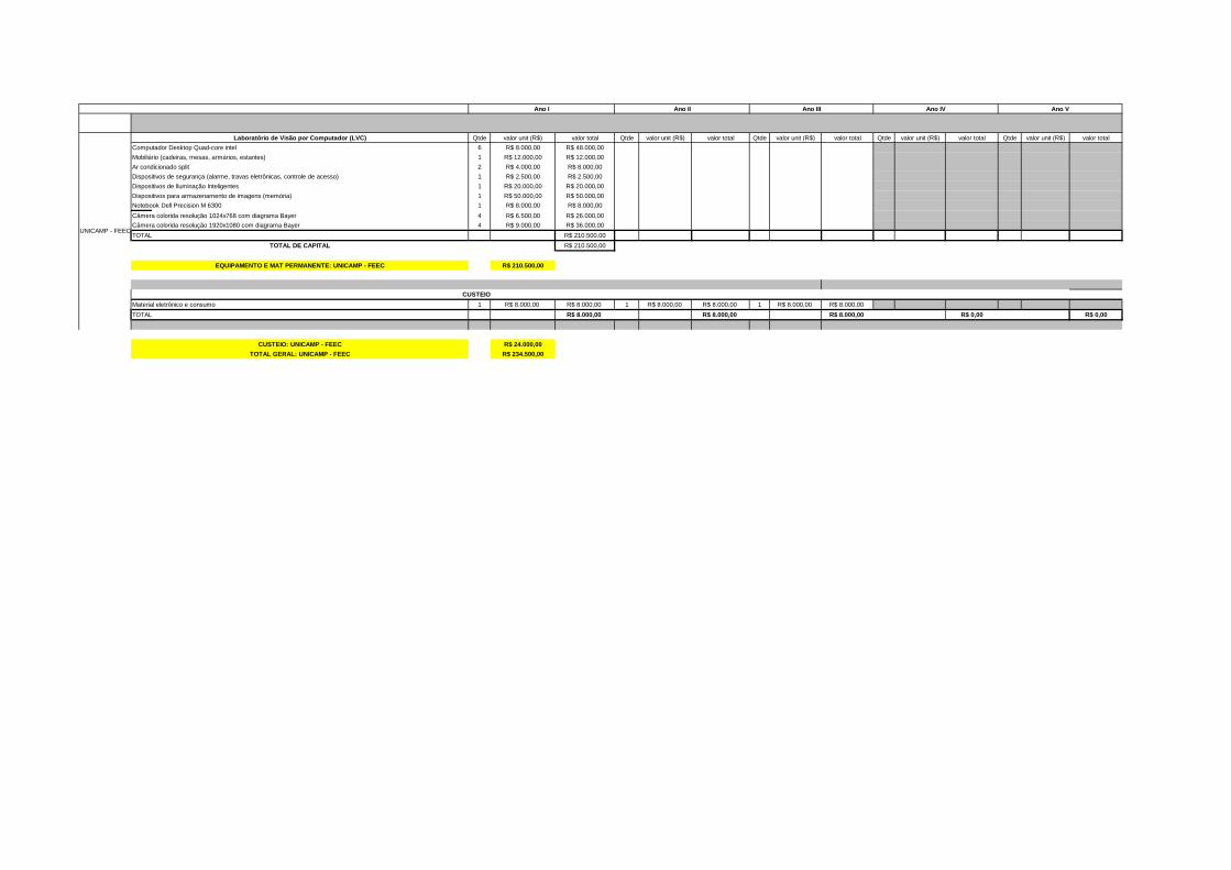
Qtde valor unit (R$) valor total Qtde valor unit (R$) valor total Qtde valor unit (R$) valor total Qtde valor unit (R$) valor total Qtde valor unit (R$) valor total
Computador Desktop Quad-core intel 6 R$ 8.000,00 R$ 48.000,00
Mobiliário (cadeiras, mesas, armários, estantes) 1 R$ 12.000,00 R$ 12.000,00
Ar condicionado split 2 R$ 4.000,00 R$ 8.000,00
Dispositivos de segurança (alarme, travas eletrônicas, controle de acesso) 1 R$ 2.500,00 R$ 2.500,00
Dispositivos de Iluminação Inteligentes 1 R$ 20.000,00 R$ 20.000,00
Dispositivos para armazenamento de imagens (memória) 1 R$ 50.000,00 R$ 50.000,00
Notebook Dell Precision M 6300 1 R$ 8.000,00 R$ 8.000,00
Câmera colorida resolução 1024x768 com diagrama Bayer 4 R$ 6.500,00 R$ 26.000,00
Câmera colorida resolução 1920x1080 com diagrama Bayer 4 R$ 9.000,00 R$ 36.000,00
TOTAL R$ 210.500,00
R$ 210.500,00
R$ 210.500,00
Material eletrônico e consumo 1 R$ 8.000,00 R$ 8.000,00 1 R$ 8.000,00 R$ 8.000,00 1 R$ 8.000,00 R$ 8.000,00
TOTAL R$ 8.000,00 R$ 8.000,00 R$ 8.000,00 R$ 0,00 R$ 0,00
R$ 24.000,00
R$ 234.500,00
Ano I Ano II Ano III
UNICAMP - FEEC
Laboratório de Visão por Computador (LVC)
TOTAL DE CAPITAL
EQUIPAMENTO E MAT PERMANENTE: UNICAMP - FEEC
CUSTEIO
Ano V
CUSTEIO: UNICAMP - FEEC
TOTAL GERAL: UNICAMP - FEEC
Ano IV
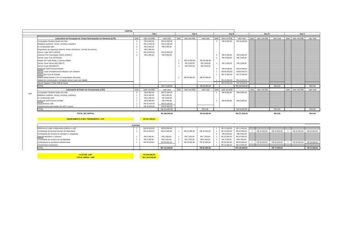
Qtde valor unit (R$) valor total Qtde valor unit (R$) valor total Qtde valor unit (R$) valor total Qtde valor unit (R$) valor total Qtde valor unit (R$) valor total
Computador Desktop Quad-core intel 3 R$ 8.000,00 R$ 24.000,00 2 R$ 8.000,00 R$ 16.000,00
Mobiliário (cadeiras, mesas, armários, estantes) 1 R$ 12.000,00 R$ 12.000,00
Ar condicionado split 2 R$ 4.000,00 R$ 8.000,00
Dispositivos de segurança (alarme, travas eletrônicas, controle de acesso) 1 R$ 2.500,00
Sensor Laser SICK LMS200 1 R$ 18.000,00 R$ 18.000,00
Câmera CCD Grasshoper GRAS-14S5M-C 2 R$ 4.500,00 R$ 9.000,00 2 R$ 4.500,00 R$ 9.000,00
Sensor Laser LLD-150-RS232 1 R$ 3.500,00 R$ 3.500,00
Módulo de Fusão Radar e Câmera Delphi 1 R$ 25.000,00 R$ 25.000,00
Sensor Sonar Sense MIC130DTC 2 R$ 2.500,00 R$ 5.000,00 2 R$ 2.500,00 R$ 5.000,00
Sensor Sonar MIC600DTC 1 R$ 9.000,00 R$ 9.000,00
Notebook Dell Precision M 6300 3 R$ 8.000,00 R$ 24.000,00
Sensor Laser Omnidirecional Velodyne com software 1 R$ 90.000,00 R$ 90.000,00
Viatura tipo Fora de Estrada 1 R$ 75.000,00 R$ 75.000,00
Mobile Robot Pioneer 3 AT & Componentes-Sensores 1 R$ 55.000,00 R$ 55.000,00
Módulo de comunicação e simulação sensor Laser sick Matlab 1 R$ 15.000,00 R$ 15.000,00
Sensor Navtech 77GHz FMCW Radar 1 R$ 18.000,00 R$ 18.000,00
TOTAL R$ 71.000,00 R$ 94.000,00 R$ 255.500,00 R$ 0,00 R$ 0,00
Qtde valor unit (R$) valor total Qtde valor unit (R$) valor total Qtde valor unit (R$) Qtde valor unit (R$) Qtde valor unit (R$) valor total
Computador Desktop Quad-core intel 4 R$ 8.000,00 R$ 32.000,00 1 R$ 8.000,00 R$ 8.000,00
Mobiliário (cadeiras, mesas, armários, estantes) 1 R$ 6.000,00 R$ 6.000,00
Ar condicionado split 1 R$ 4.000,00 R$ 4.000,00
Notebook Dell Precision M 6300 1 R$ 8.000,00 R$ 8.000,00 1 R$ 8.000,00 R$ 8.000,00
Equipamentos CAN 1 R$ 35.000,00 R$ 35.000,00
Equipamentos para Redes AD HOC e outros 1 R$ 30.000,00 R$ 30.000,00
TOTAL R$ 115.000,00 R$ 0,00 R$ 16.000,00 R$ 0,00 R$ 0,00
R$ 186.000,00 R$ 94.000,00 R$ 271.500,00 R$ 0,00 R$ 0,00
R$ 551.500,00
Reforma em salas e laboratórios (elétrica e civil) 1 R$ 35.000,00 R$ 35.000,00 1 R$ 12.000,00 R$ 12.000,00
Contratação de pessoal (técnico de laboratório) 1 R$ 42.000,00 R$ 42.000,00 1 R$ 42.000,00 R$ 42.000,00 1 R$ 42.000,00 R$ 42.000,00 1 R$ 42.000,00 R$ 42.000,00 1 R$ 42.000,00 R$ 42.000,00
Contratação de serviços de usinagem e adaptação 1 R$ 8.000,00 R$ 8.000,00
Material eletrônico e consumo 1 R$ 5.000,00 R$ 5.000,00 1 R$ 7.000,00 R$ 7.000,00 1 R$ 10.000,00 R$ 10.000,00
Contratação de serviços de contabilidade 1 R$ 3.200,00 R$ 3.200,00 2 R$ 3.200,00 R$ 6.400,00 2 R$ 3.200,00 R$ 6.400,00
Contrtatação de assistente administrativo 1 R$ 30.000,00 R$ 30.000,00 1 R$ 30.000,00 R$ 30.000,00 1 R$ 30.000,00 R$ 30.000,00 1 R$ 30.000,00 R$ 30.000,00 1 R$ 30.000,00 R$ 30.000,00
Consumíveis mecâncicos 1 R$ 10.000,00 R$ 10.000,00
TOTAL R$ 115.200,00 R$ 85.400,00 R$ 118.400,00 R$ 72.000,00 R$ 72.000,00
R$ 463.000,00
R$ 1.014.500,00
CAPITAL
Ano II Ano III Ano IV Ano VAno I
Laboratório de Redes de Comunicação (LRC)
TOTAL DE CAPITAL
Laboratório de Percepção de Tempo Real baseada em Se nsores (LPS)
USP
CUSTEIO
EQUIPAMENTO E MAT PERMANENTE: USP
CUSTEIO: USP
TOTAL GERAL: USP
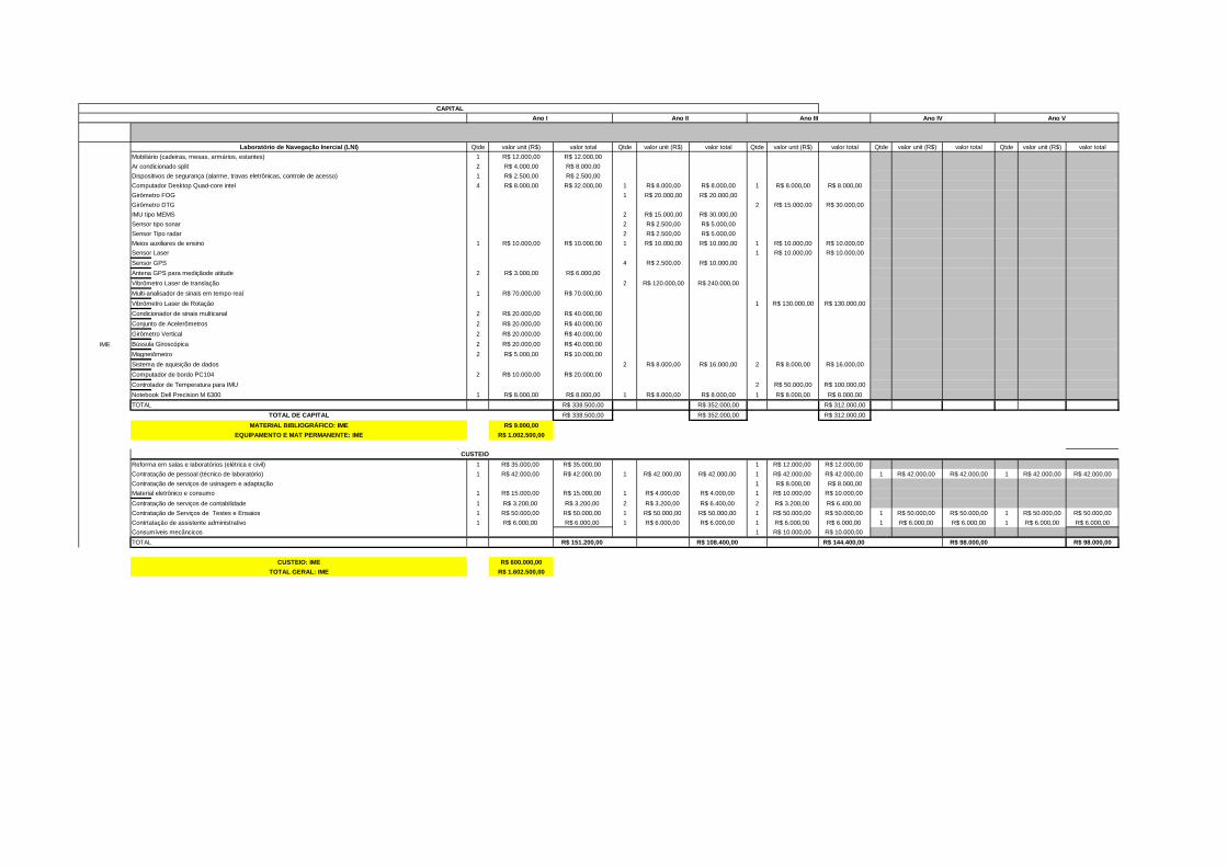
Qtde valor unit (R$) valor total Qtde valor unit (R$) valor total Qtde valor unit (R$) valor total Qtde valor unit (R$) valor total Qtde valor unit (R$) valor total
Mobiliário (cadeiras, mesas, armários, estantes) 1 R$ 12.000,00 R$ 12.000,00
Ar condicionado split 2 R$ 4.000,00 R$ 8.000,00
Dispositivos de segurança (alarme, travas eletrônicas, controle de acesso) 1 R$ 2.500,00 R$ 2.500,00
Computador Desktop Quad-core intel 4 R$ 8.000,00 R$ 32.000,00 1 R$ 8.000,00 R$ 8.000,00 1 R$ 8.000,00 R$ 8.000,00
Girômetro FOG 1 R$ 20.000,00 R$ 20.000,00
Girômetro DTG 2 R$ 15.000,00 R$ 30.000,00
IMU tipo MEMS 2 R$ 15.000,00 R$ 30.000,00
Sensor tipo sonar 2 R$ 2.500,00 R$ 5.000,00
Sensor Tipo radar 2 R$ 2.500,00 R$ 5.000,00
Meios auxiliares de ensino 1 R$ 10.000,00 R$ 10.000,00 1 R$ 10.000,00 R$ 10.000,00 1 R$ 10.000,00 R$ 10.000,00
Sensor Laser 1 R$ 10.000,00 R$ 10.000,00
Sensor GPS 4 R$ 2.500,00 R$ 10.000,00
Antena GPS para mediçãode atitude 2 R$ 3.000,00 R$ 6.000,00
Vibrômetro Laser de translação 2 R$ 120.000,00 R$ 240.000,00
Multi-analisador de sinais em tempo real 1 R$ 70.000,00 R$ 70.000,00
Vibrômetro Laser de Rotação 1 R$ 130.000,00 R$ 130.000,00
Condicionador de sinais multicanal 2 R$ 20.000,00 R$ 40.000,00
Conjunto de Acelerômetros 2 R$ 20.000,00 R$ 40.000,00
Girômetro Vertical 2 R$ 20.000,00 R$ 40.000,00
Bússula Giroscópica 2 R$ 20.000,00 R$ 40.000,00
Magnetômetro 2 R$ 5.000,00 R$ 10.000,00
Sistema de aquisição de dados 2 R$ 8.000,00 R$ 16.000,00 2 R$ 8.000,00 R$ 16.000,00
Computador de bordo PC104 2 R$ 10.000,00 R$ 20.000,00
Controlador de Temperatura para IMU 2 R$ 50.000,00 R$ 100.000,00
Notebook Dell Precision M 6300 1 R$ 8.000,00 R$ 8.000,00 1 R$ 8.000,00 R$ 8.000,00 1 R$ 8.000,00 R$ 8.000,00
TOTAL R$ 338.500,00 R$ 352.000,00 R$ 312.000,00
R$ 338.500,00 R$ 352.000,00 R$ 312.000,00
R$ 9.000,00
R$ 1.002.500,00
Reforma em salas e laboratórios (elétrica e civil) 1 R$ 35.000,00 R$ 35.000,00 1 R$ 12.000,00 R$ 12.000,00
Contratação de pessoal (técnico de laboratório) 1 R$ 42.000,00 R$ 42.000,00 1 R$ 42.000,00 R$ 42.000,00 1 R$ 42.000,00 R$ 42.000,00 1 R$ 42.000,00 R$ 42.000,00 1 R$ 42.000,00 R$ 42.000,00
Contratação de serviços de usinagem e adaptação 1 R$ 8.000,00 R$ 8.000,00
Material eletrônico e consumo 1 R$ 15.000,00 R$ 15.000,00 1 R$ 4.000,00 R$ 4.000,00 1 R$ 10.000,00 R$ 10.000,00
Contratação de serviços de contabilidade 1 R$ 3.200,00 R$ 3.200,00 2 R$ 3.200,00 R$ 6.400,00 2 R$ 3.200,00 R$ 6.400,00
Contratação de Serviços de Testes e Ensaios 1 R$ 50.000,00 R$ 50.000,00 1 R$ 50.000,00 R$ 50.000,00 1 R$ 50.000,00 R$ 50.000,00 1 R$ 50.000,00 R$ 50.000,00 1 R$ 50.000,00 R$ 50.000,00
Contrtatação de assistente administrativo 1 R$ 6.000,00 R$ 6.000,00 1 R$ 6.000,00 R$ 6.000,00 1 R$ 6.000,00 R$ 6.000,00 1 R$ 6.000,00 R$ 6.000,00 1 R$ 6.000,00 R$ 6.000,00
Consumíveis mecâncicos 1 R$ 10.000,00 R$ 10.000,00
TOTAL R$ 151.200,00 R$ 108.400,00 R$ 144.400,00 R$ 98.000,00 R$ 98.000,00
R$ 600.000,00
R$ 1.602.500,00
CUSTEIO: IME
TOTAL GERAL: IME
Ano V
IME
Laboratório de Navegação Inercial (LNI)
TOTAL DE CAPITAL
EQUIPAMENTO E MAT PERMANENTE: IME
CUSTEIO
Ano IV
CAPITAL
Ano I Ano II Ano III
MATERIAL BIBLIOGRÁFICO: IME
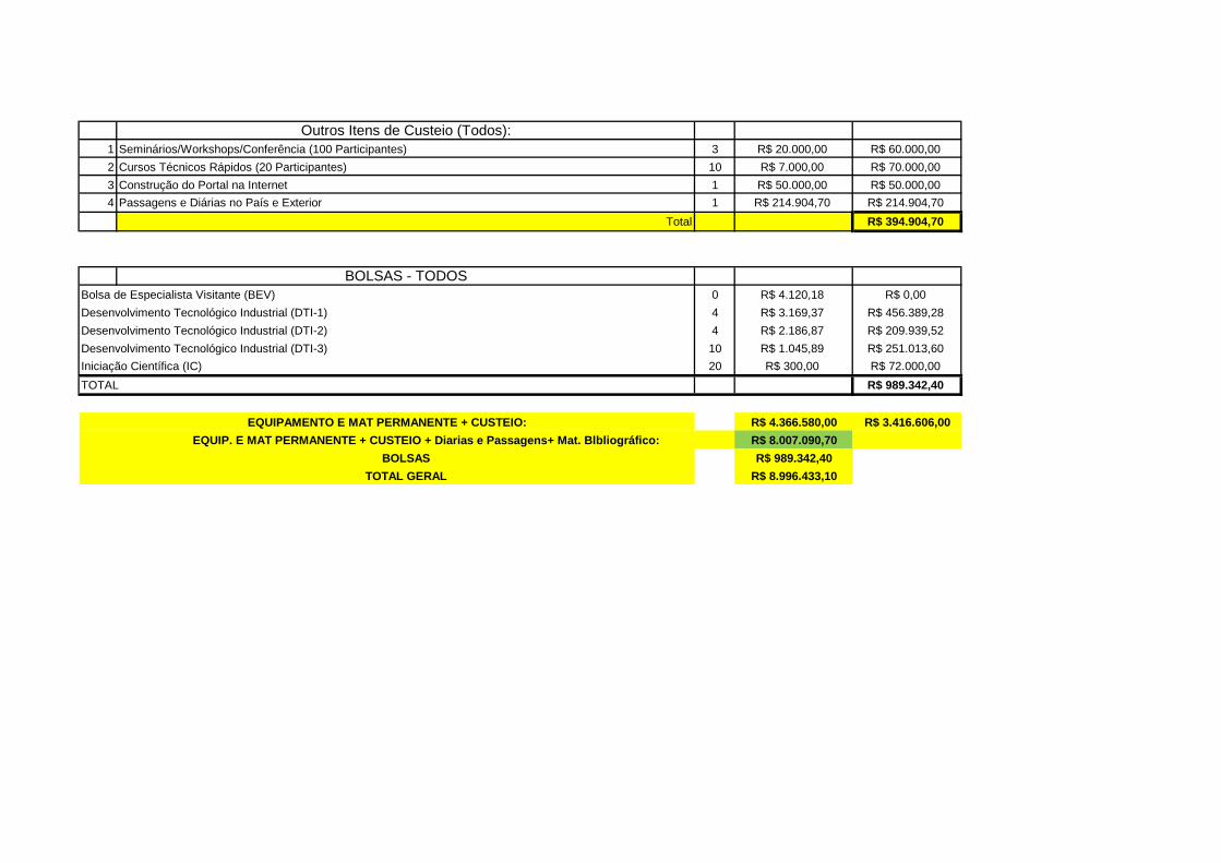
Outros Itens de Custeio (Todos):1 Seminários/Workshops/Conferência (100 Participantes) 3 R$ 20.000,00 R$ 60.000,00
2 Cursos Técnicos Rápidos (20 Participantes) 10 R$ 7.000,00 R$ 70.000,00
3 Construção do Portal na Internet 1 R$ 50.000,00 R$ 50.000,00
4 Passagens e Diárias no País e Exterior 1 R$ 214.904,70 R$ 214.904,70
Total R$ 394.904,70
BOLSAS - TODOSBolsa de Especialista Visitante (BEV) 0 R$ 4.120,18 R$ 0,00
Desenvolvimento Tecnológico Industrial (DTI-1) 4 R$ 3.169,37 R$ 456.389,28
Desenvolvimento Tecnológico Industrial (DTI-2) 4 R$ 2.186,87 R$ 209.939,52
Desenvolvimento Tecnológico Industrial (DTI-3) 10 R$ 1.045,89 R$ 251.013,60
Iniciação Científica (IC) 20 R$ 300,00 R$ 72.000,00
TOTAL R$ 989.342,40
R$ 4.366.580,00 R$ 3.416.606,00
R$ 8.007.090,70
BOLSAS R$ 989.342,40
TOTAL GERAL R$ 8.996.433,10
EQUIPAMENTO E MAT PERMANENTE + CUSTEIO:
EQUIP. E MAT PERMANENTE + CUSTEIO + Diarias e Passa gens+ Mat. Blbliográfico:
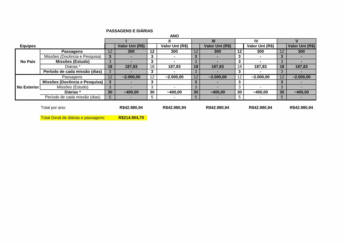
Equipes Valor Unt (R$) Valor Unt (R$) Valor Unt (R$) Valor Unt (R$) Valor Unt (R$)Passagens 12 300 12 300 12 300 12 300 12 300
Missões (Docência e Pesquisa) 3 - 3 - 3 - 3 - 3 -Missões (Estudo) 3 - 3 - 3 - 3 - 3 -
Diárias * 18 187,83 18 187,83 18 187,83 18 187,83 18 187,83Período de cada missão (dias) 3 - 3 - 3 - 3 - 3 -
Passagens 12 ~2.000,00 12 ~2.000,00 12 ~2.000,00 12 ~2.000,00 12 ~2.000,00Missões (Docência e Pesquisa) 3 - 3 3 - 3 3 -
Missões (Estudo) 3 - 3 - 3 - 3 - 3 -Diárias * 30 ~400,00 30 ~400,00 30 ~400,00 30 ~400,00 30 ~400,00
Período de cada missão (dias) 5 - 5 - 5 - 5 - 5 -
Total por ano: R$42.980,94 R$42.980,94 R$42.980,94 R$42.980,94 R$42.980,94
Total Geral de diárias e passagens: R$214.904,70
IV V
No País
No Exterior
PASSAGENS E DIÁRIASANO
I II III