Manual del Propietário / Owner’s Manual Certificado de ... · d) Sustitución de rodamientos,...
50
Rev.01 - Marzo / March 2018 Código/Code: 036-00198-000 Manual del Propietário / Owner’s Manual Certificado de Garantía / Warranty Certificate CC 305 - CC 335 - CC 355 AIRE ACONDICIONADO RODOVIARIO - URBANO / AIR CONDITIONER COACHBUS - CITY BUS
Transcript of Manual del Propietário / Owner’s Manual Certificado de ... · d) Sustitución de rodamientos,...

Rev.01 - Marzo / March 2018Código/Code: 036-00198-000
Manual del Propietário / Owner’s ManualCertificado de Garantía / Warranty Certificate
CC 305 - CC 335 - CC 355
AIRE ACONDICIONADO RODOVIARIO - URBANO / AIR CONDITIONER COACHBUS - CITY BUS

ESPA
ÑO
L

INTRODUCCIÓN
VALEO Climatização do Brasil - Veículos Comerciais S/A desarrolla sus productos preocupada en ofrecer a los pasajeros un ambiente confortable, buscando siempre la mejor condición de climatización.
Los equipos poseen un diseño que proporciona una perfecta integración con el vehículo facilitando la operación y manutención.Con dimensionamiento optimizado, garantizan una alta capacidad de resfriamiento y un bajo nivel de ruido.
Este manual fue desarrollado con la finalidad de presentar aspectos importantes de funcionamiento, operación y manutención, para que se obtenga el mejor desempeño del equipo de aire acondicionado.
Para asegurar que el equipo tenga una larga vida útil y libre de problemas es imprescindible que las instrucciones de operación y manutención, descritas en este manual, sean seguidas y ejecutadas periódicamente.
Los controles instalados por VALEO Climatização do Brasil - Veículos Comerciais S/A, que son utilizados por el conductor, están debidamente ilustrados y explicados en este manual.
Es importante que el conductor lea atentamente las instrucciones de este manual antes de iniciar la operación del equipo de aire acondicionado.
VALEO Climatização do Brasil - Veículos Comerciais S/A mantiene una red de servicio autorizado con herramientas, equipos y un equipo entrenado para ejecutar cualquier tipo de manutención dentro de patrones de calidad.
Agradecemos la preferencia por los productos VALEO Climatização do Brasil - Veículos Comerciais S/A.En el caso de que tenga dudas, entre en contacto con la red de servicio autorizado VALEO Climatização do Brasil - Veículos Comerciais S/A más cercana o contacte el departamento de asistencia técnica.
CC 305 - CC 335 - CC 355
3

CC 305 - CC 335 - CC 355ÍNDICE
TÉRMINOS DE GARANTÍATérminos de Garantía...............................................................................................................................................................................................................................5
MANUTENCIÓN PREVENTIVARutinas de Manutención Preventiva................................................................................................................................................................................................................................................6Gas refrigerante R134a..............................................................................................................................................................................................................................................7Aceite................................................................................................................................................................................................................................................................................7Filtro Secador.................................................................................................................................................................................................................................................................7Junta de Sellado del Compresor..........................................................................................................................................................................................................................7Conductos...............................................................................................................................................................................................................................................................................7Correas..............................................................................................................................................................................................................................................................................7
IDENTIFICACIÓN DEL EQUIPOTarjeta de Identificación.............................................................................................................................................................................................................................................9
FUNCIONAMIENTO DEL AIRE ACONDICIONADO1- Funcionamiento del Aire Acondicionado................................................................................................................................................................................................................................................101.1- Operación del Controlador GL-W163 / GL-W210...............................................................................................................................................................................................................................121.2- Accionamiento del Controlador................................................................................................................................................................................................................................................131.3- Lectura de la Temperatura................................................................................................................................................................................................................................................131.4- Programando el SET-POINT....................................................................................................................................................................................................................131.5- Modo Automático....................................................................................................................................................................................................................................................131.6- Modo Ventilación.......................................................................................................................................................................................................................................................................131.7- Modo Refrigeración............................................................................................................................................................................................................................................141.8- Modo de Calentamiento......................................................................................................................................................................................................................................141.9- Calentamiento por Convectores.....................................................................................................................................................................................................................141.10- Renovación del Aire.................................................................................................................................................................................................................................141.11- Temperatura Interna e Externa.................................................................................................................................................................................................................141.12- Fallas.........................................................................................................................................................................................................................................................151.13- Alarma de Fallas del Controlador GL-W163......................................................................................................................................................................................................151.14- Alarma de Fallas del Controlador GL-W210...............................................................................................................................................................................................15
DESCRIPCIÓN DEL EQUIPO2- Especificaciones Técnicas..........................................................................................................................................................................................................................................................................162.1- Componentes del Evaporador........................................................................................................................................................................................................172.2- Componentes del Condensador ..........................................................................................................................................................................................................................182.3- Componentes del Compresor BOCK FKX 40/655K...................................................................................................................................................................................192.4- Componentes Eléctricos.........................................................................................................................................................................................................................20
SISTEMA ELÉCTRICO3- Placa Comando Eléctrico RODOVIÁRIO GL-T047 / 24V.....................................................................................................................................................................................................................................213.1- Diagrama Eléctrico PLACA DE COMANDO RODOVIÁRIO GL-T047 / 24V GL-W210......................................................................................................................223.2- Diagrama Eléctrico PLACA DE COMANDO RODOVIÁRIO GL-T047 / 24V GL-W163 ...........................................................................................................................23
SEGURIDAD4- Precauciones de Seguridad...................................................................................................................................................................................................................................................24
SOSTENIBILIDAD5- Desecho de Productos...................................................................................................................................................................................................................................................25

TÉRMINOS DE GARANTÍA
Términos de Garantía
VALEO Climatização do Brasil - Veículos Comerciais S/A garantiza sus productos por el período de un año, de acuerdo con los términos relacionados a seguir:
1 - La garantía tendrá validez por el plazo especificado arriba, contado a partir de la fecha de instalación del equipo que consta en el certificado de garantía, inclusive cuando la propiedad del producto haya sido transferida.
2 – Si el equipo es instalado por un tercero, VALEO Climatização do Brasil - Veículos Comerciais S/A garantiza solamente el producto y no su instalación.
3 - Durante el período estipulado, la garantía cubre totalmente la mano de obra y las piezas empleadas en la reparación de defectos debidamente constatados como siendo de: fabricación del equipo; falla prematura de material y defectos de componentes utilizados en la fabricación del mismo.
4 - Solamente un técnico de la red de servicios autorizados VALEO Climatização do Brasil - Veículos Comerciais S/A está habilitado para reparar defectos cubiertos por la garantía.
5 - La aprobación de la garantía está condicionada al análisis técnico del defecto presentado en el componente y condiciones operacionales a las que fue sometido el equipo.
6 - Ninguna reivindicación será aceptada si el vehículo continúa siendo usado después de constatado el defecto, aunque haya falta de piezas, atraso en el transporte o cualquier otro incidente.
7 - La Garantía perderá su Validez
a) Si la instalación o utilización del producto está en desacuerdo con las recomen-daciones técnicas de VALEO Climatização do Brasil - Veículos Comerciais S/A.b) Si el producto sufre cualquier daño provocado por: uso inadecuado, descuido, accidente, fallas provocadas por agentes externos e inclusive falta de manutención preventiva (vea el manual del propietario) o también servicios ejecutados por personas no calificadas.c) Si el certificado de garantía y/o número de serie del producto está adulterado, rasurado o dañado.d) Si defectos o desempeño insatisfactorios fueron provocados por la utilización de piezas no originales y en desacuerdo con las especificaciones técnicas de VALEO Climatização do Brasil - Veículos Comerciais S/A.
8 - La Garantía NO CUBRE
a) Desplazamiento del producto para arreglo. Si el consumidor desea ser atendi-do en el local donde opera el producto, quedará a criterio del Servicio Autorizado la cobranza o no de la tasa de visita.b) La atención al consumidor, gratuito o remunerado, en ciudades que no posean Servicios Autorizados. Siendo así, los gastos con desplazamiento son de total responsabilidad del propietario. c) Falta de manutención preventiva y revisiones, conforme lo descrito en este manual, en el ítem manutención preventiva.d) Sustitución de rodamientos, correas, filtros en general y aceite lubricante, pues son considerados ítems de desgaste natural.Rodamiento y correas poseen garantía restringida conforme lo citado a seguir: - Rodamientos en general = 60.000km ó 1 año, lo que ocurra antes. - Correas en general = 20.000km ó 3 meses, lo que ocurra antes. - Alternadores = 1 año sin límite de kilometraje, respetando sin embargo las condiciones establecidas en estos términos de garantía y las especificaciones técnicas del fabricante.e) Pérdidas o lucros cesantes ocasionados por la parada del vehículo debido al no funcionamiento del equipo.
CC 305 - CC 335 - CC 355
5

MANUTENCIÓN PREVENTIVA
- Rutinas de Manutención Preventiva
IMPORTANTE: no realizar la manutención preventiva conforme lo descrito en este capítulo, implicará en la pérdida total o parcial de la garantía.Las acciones de manutención preventiva descritas en este manual, fueron consideradas para condiciones operacionales normales.En el caso de que las condiciones sean de gran solicitud y contaminación ambiental, la frecuencia de las acciones debe ser mayor.NOTA (*): al realizar limpieza utilizando agua, proteja los componentes eléctricos y electrónicos para evitar daños.
1 - Limpiar o cambiar el filtro del aire de retorno.2 - Inspeccionar la condición de tensión y alineación de las correas del compresor y alternador observando señales de desgaste.
1 - Ejecutar rutinas de manutención preventiva semanal.2 - Limpiar la serpentina del condensador; (Utilice solamente agua y jabón neutro no agresivo al cobre y al aluminio). Ver Nota (*)3 - Verificar el cierre de los capós del evaporador para evitar la entrada de aire falso en el equipo.4 - Verificar la carga de refrigerante: después de 15 min. de funcionamiento el refrigerante debe fluir a través del visor de líquido sin formación de burbujas.5 - Verificar el nivel del aceite del compresor: después de 15 min. de funcionamiento debe estar entre 3/4 a 1/4 del visor de aceite.6 - Prueba de funcionamiento de las funciones del equipo: modo refrigeración / ventilación (velocidad alta y baja) / calentamiento / renovación de aire.7 - Lubricar componentes del soporte del compresor. Incluye articulaciones, ejes, bujes y poleas, cuando los haya.
1 - Ejecutar rutinas de manutención preventiva mensual.2 - Medir presiones de succión de descarga, temperatura y condición de la línea de succión.3 - Verificar aprietes de los cables de potencia en el alternador, fusible general, placa eléctrica y motor de arranque.4 - Medir consumo de corrientes de los ventiladores del condensador y de los ventiladores del evaporador (verificar el vaciamiento del flujo de aire).5 - Medir resistencia de la bobina del embrague electromagnético.6 - Medir la tensión y corriente del alternador.
1 - Ejecutar rutinas de manutención preventiva trimestral.2 - Limpiar la serpentina del evaporador (Utilizar solamente agua y jabón neutro no agresivo al cobre o al aluminio). Ver Nota (*)3 - Limpiar los drenajes del evaporador.4 - Inspeccionar el fieltro de retención de aceite de la junta de sellado del compresor.5 - Inspeccionar visualmente si los componentes del aire acondicionado presentan señales de: vaciamiento de aceite, vaciamiento de refrigerante. Observar si hay piezas sueltas, dañadas, quebradas o presentando señales de desgaste, oxidación, deterioración y fricción con la carrocería.
1 - Ejecutar las rutinas de manutención preventiva semestral.2 - Probar la eficiencia del compresor a 1500 RPM.3 - Registrar la presión de la bomba de aceite del compresor a 1000 RPM.4 - Verificar las presiones de abertura y de cierre de los presostatos de alta y baja.5 - Verificar apriete de los tornillos del soporte del compresor y de la unidad observando los torques aplicados.6 - Limpiar el equipo de aire acondicionado eliminando impurezas alojadas en los componentes: evaporador, condensador, compresor,
SEMANAL
TRIMESTRAL
SEMESTRAL
ANUAL
MENSUAL
embrague, alternador, controlador y placa de relés. Ver nota (*)
CC 305 - CC 335 - CC 355
6
DIGA NO A LAS PIEZAS REACONDICIONADAS
ATENCIÓN: bajo ninguna circunstancia los refrigerantes deben ser descargados en la atmósfera.
MANUTENCIÓN PREVENTIVA
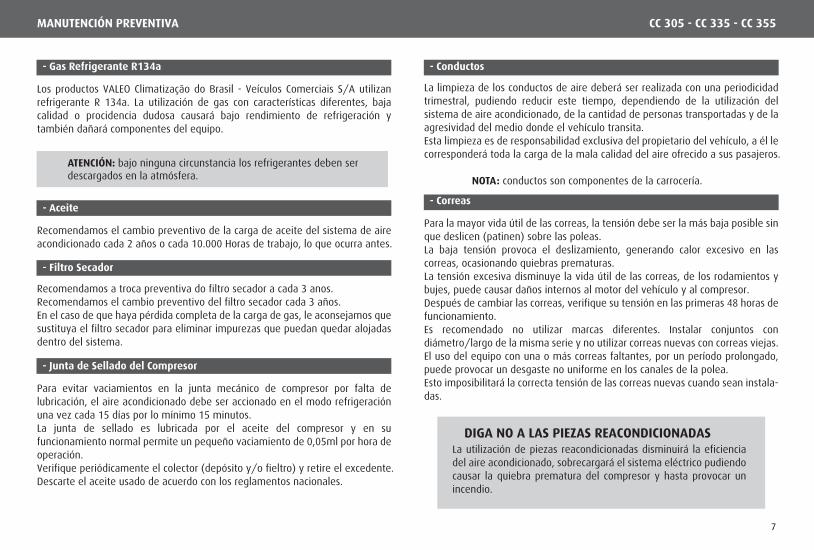
- Gas Refrigerante R134a
Los productos VALEO Climatização do Brasil - Veículos Comerciais S/A utilizan refrigerante R 134a. La utilización de gas con características diferentes, baja calidad o procidencia dudosa causará bajo rendimiento de refrigeración y también dañará componentes del equipo.
- Conductos
La limpieza de los conductos de aire deberá ser realizada con una periodicidad trimestral, pudiendo reducir este tiempo, dependiendo de la utilización del sistema de aire acondicionado, de la cantidad de personas transportadas y de la agresividad del medio donde el vehículo transita. Esta limpieza es de responsabilidad exclusiva del propietario del vehículo, a él le corresponderá toda la carga de la mala calidad del aire ofrecido a sus pasajeros.
NOTA: conductos son componentes de la carrocería.
- Correas
Para la mayor vida útil de las correas, la tensión debe ser la más baja posible sin que deslicen (patinen) sobre las poleas.La baja tensión provoca el deslizamiento, generando calor excesivo en las correas, ocasionando quiebras prematuras.La tensión excesiva disminuye la vida útil de las correas, de los rodamientos y bujes, puede causar daños internos al motor del vehículo y al compresor.Después de cambiar las correas, verifique su tensión en las primeras 48 horas de funcionamiento.Es recomendado no utilizar marcas diferentes. Instalar conjuntos con diámetro/largo de la misma serie y no utilizar correas nuevas con correas viejas. El uso del equipo con una o más correas faltantes, por un período prolongado, puede provocar un desgaste no uniforme en los canales de la polea.Esto imposibilitará la correcta tensión de las correas nuevas cuando sean instala-das.
La utilización de piezas reacondicionadas disminuirá la eficiencia del aire acondicionado, sobrecargará el sistema eléctrico pudiendo causar la quiebra prematura del compresor y hasta provocar un incendio.
- Aceite
Recomendamos el cambio preventivo de la carga de aceite del sistema de aire acondicionado cada 2 años o cada 10.000 Horas de trabajo, lo que ocurra antes.
- Filtro Secador
Recomendamos a troca preventiva do filtro secador a cada 3 anos.Recomendamos el cambio preventivo del filtro secador cada 3 años.En el caso de que haya pérdida completa de la carga de gas, le aconsejamos que sustituya el filtro secador para eliminar impurezas que puedan quedar alojadas dentro del sistema.
- Junta de Sellado del Compresor
Para evitar vaciamientos en la junta mecánico de compresor por falta de lubricación, el aire acondicionado debe ser accionado en el modo refrigeración una vez cada 15 días por lo mínimo 15 minutos.La junta de sellado es lubricada por el aceite del compresor y en su funcionamiento normal permite un pequeño vaciamiento de 0,05ml por hora de operación.Verifique periódicamente el colector (depósito y/o fieltro) y retire el excedente.Descarte el aceite usado de acuerdo con los reglamentos nacionales.
CC 305 - CC 335 - CC 355
7

Nota: en el caso de que ocurra falla de instalación, la Red de Servicio Autorizado VALEO Climatização do Brasil - Veículos Comerciais S/A, antes de realizar la reparación, deberá contactar a la montadora / ensambladora para obtener la aprobación de los reparaciones y la autorización para la emisión de Nota fiscal y de prestaciónde servicios.
Los ítems, que están a continuación, son de responsabilidad de la montadora / ensambladora.
Problemas con cualquier componente del aire acondicionado del conductor, vaciamientos y mal funcionamiento.
IMPORTANTE: limpiar el filtro de retorno de aire del aire acondicionado del conductor por lo mínimo una vez por semana.
Mala fijación.
Vaciamientos en las conexiones y puntos de soldadura.
Daños por fricción / interferencia con el chasis o componentes.
Exceso o falta de torque en los tornillos de fijación.
Montaje en desacuerdo con el proyecto.
Desalineación de poleas, exceso o falta de tensión en las correas.
Procedimiento de prueba de vaciamiento.
Proceso de vacío y carga de gas refrigerante.
Evaporador del Conductor
Tuberías,mangueras,drenajes yChicote
Soporte delcompresor /alternador
Proceso decarga de gas
CC 305 - CC 335 - CC 355MANUTENCIÓN PREVENTIVA
IMPORTANTE: las acciones de manutención preventiva deberán ser realizadas por el propietario del vehículo.No realizar la manutención preventiva conforme lo descrito en este capítulo, implicará en la pérdida total o parcial de la garantía.
ATENCIÓN: en el caso de que ocurra un problema en el circuito de refrigeración, éste deberá ser reparado por un taller autorizado o por un profesional calificado.Si el equipo es instalado por un tercero, VALEO Climatização do Brasil - Veículos Comerciais S/A garantiza solamente el producto y no su instalación.
8

- Tarjeta de Identificación
Es de fundamental importancia, en casos de pedidos de piezas de reposición, y demás correspondencias, que el cliente identifique el modelo del equipo de aire acondicionado, informando el número de serie, modelo y fecha de fabricación del mismo.Estas informaciones podrán ser encontradas en el certificado de garantía del aire acondicionado y en la tarjeta de identificación.En la tarjeta consta también el tipo de gas refrigerante utilizado y la cantidad necesaria para el equipo.
Informaciones referente a aplicaciones como: n° de serie y modelo de la carroceía; serie y modelo del chasis, también son importantes para la identificación de piezas que componen el equipo de aire acondicionado. Para identificacíon de la carrocería y chasis los manuales de los mismos deberán ser consultados.
CC 305 - CC 335 - CC 355IDENTIFICACIÓN DEL EQUIPO
la cantidad de refrigerante puede variarsegún la aplicación.
9
Nota: diseños ilustrativos.
17
14
28
1
167
15
6
13
11
13
5
4
3
12
18
9
9
10
16
11
CC 305 - CC 335 - CC 355FUNCIONAMIENTO DEL AIRE ACONDICIONADO
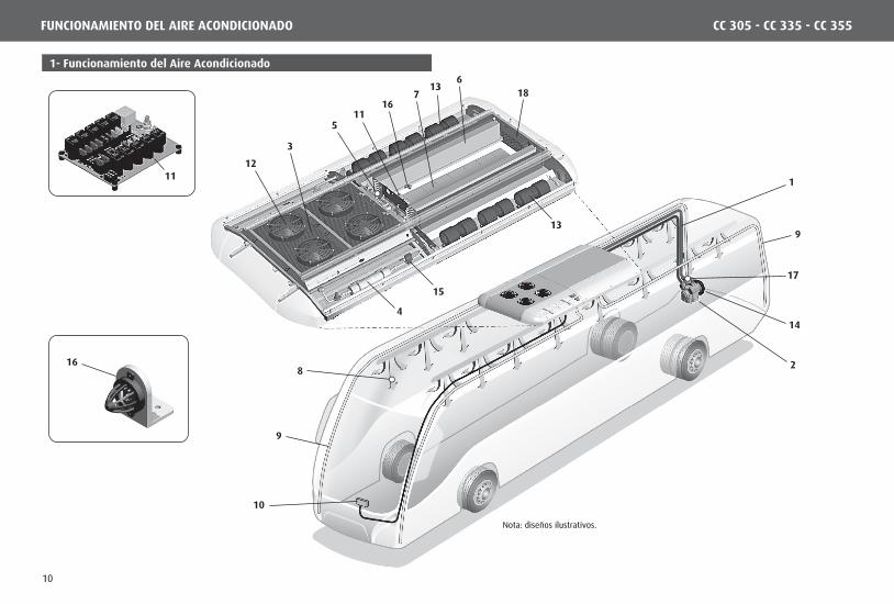
1- Funcionamiento del Aire Acondicionado
10

Ventilador del condensadorLos ventiladores del condensador, así como el compresor, solamente serán accionados cuando el aire acondicionado esté funcionando en el "Modo Refrigeración."
Fluido refrigerante
Tiene como principal función propiciar la disipación del calor absorbido por el fluido refrigerante a lo largo del sistema de refrigeración. En el condensador el fluido refrigerante sobrecalentado, al perder calor para el medio ambiente, pasa del estado gaseoso para el estado líquido.
Condensador
Filtro secadorTiene la finalidad de retener impurezas y/o humedad que pueda haber en el sistema impidiendo que lleguen en la válvula de expansión.
Válvula termostática de expansiónLa válvula de expansión restringe la entrada del refrigerante que viene del condensador en alta presión y tiene como función regular el flujo de gas refrigerante que pasa en el evaporador buscando mantener estable la presión y la temperatura en la salida de la serpentina.
CompresorCuando está en funcionamiento, el compresor succiona el fluido refrigerante del evaporador en el estado gaseoso y en baja presión, lo comprime elevando la presión y la temperatura y, lo descarga para el condensador
SIST
EMA
MEC
ÁN
ICO
Accionamiento del compresorEl compresor hace la tracción por el motor del vehículo a través de un sistema de correas y es accionado por un embrague electromagnético siempre que el aire acondicionado esté operando en el "Modo Refrigeración."
Ventilador del evaporadorLos ventiladores del evaporador son accionados en los modos ventilación y refrigeración y pueden operar en dos velocidades. El control de velocidad puede ser automático o manual.
Sensor de temperaturaLa temperatura interna es detectada por el sensor de temperatura localizado en el retorno de aire.
PresostatosLos presostatos son dispositivos eléctricos que monitorean las presiones de operación del equipo de aire acondicionado. Siempre que ocurra una alteración en las presiones normales de operación, para evitar quiebras, el compresor será apagado inmediatamente. Observación: las presiones son monitoreadas continuamente inclusive cuando el aire acondicionado esté apagado.
SIST
EMA
ELÉ
CTR
ICO
EvaporadoresEs en los evaporadores que el fluido refrigerante, ahora en baja presión, pasa del estado líquido para el gaseoso, absorbiendo en este proceso el calor del ambiente interno del autobús.
ControladorInstalado en el tablero de instrumentos, permite que el conductor programe la temperatura de set-point y visualice el valor de la temperatura interna del vehículo, ofreciendo el total control del clima interno del autobús. Set-point: es el valor de la temperatura deseada en el interior del vehículo, regulado por el operador (conductor).
Placa de RelésLa placa de relés recibe los comandos del controlador y acciona los ventiladores del condensador, evaporador y el compresor, conforme el modo de operación seleccionado.
Filtro de aireEl filtro de retorno de aire retiene las impurezas suspendidas en el aire evitando la acumulación de residuos en las serpentinas del evaporador.
Circulación de aireEl aire, después de ser enfriado en el evaporador es distribuido en el interior del autobús por la acción de los ventiladores.
DrenajesSirven para conducir la humedad condensada en las serpentinas del evaporador acumulada en la bandeja de condensación para fuera del vehículo.
SIST
EMA
MEC
ÁN
ICO
SIST
EMA
ELÉ
CTR
ICO
Renovación del airePermite que el aire exterior entre con el fin deeliminar las impurezas y olores no deseados en elinterior del vehículo.
18
1
2
3
4
5
6
7
8
9
10
11
12
13
14
16
Válvula solenóideUna válvula solenoide se utiliza para detener el flujo derefrigerante a través de una línea. Es una válvula de cierrecontrolada remotamente y operada eléctricamente.
15
17
CC 305 - CC 335 - CC 355FUNCIONAMIENTO DEL AIRE ACONDICIONADO
En el equipo de aire acondicionado el fluido refrigeran-te está confinado dentro del sistema. Él actúa absorbiendo el calor del ambiente interno del vehículo, en el evaporador y lo transporta hasta el condensador donde el calor es transferido para el ambiente externo. Los productos VALEO Climatização do Brasil - Veículos Comerciais S/A, utilizan refrigerante R134a, conforme la ley de protección al medio ambiente.
11

1
3
8
4
11 2 7
5 6
9 10
1 - Display numérico.
2 - Tecla control de refrigeración / calefacción automática (AUTO).
3 - Tecla control de ventilación (VENT.).
4 - Tecla control renovación del aire (RENOV.).
5 - Tecla (AUMENTO).
6 - Tecla (BAJO).
7 - Indicativo "modo de refrigeración / calefacción''.
8 - Indicativo "modo automático’’.
9 - Indicativo “modo ventilación velocidad baja”.
10 - Indicativo “modo ventilación velocidad alta”.
11 - Indicativo "modo de renovación del aire''.
12 - Tecla verificación de la temperatura interior / exterior (TEMP).
13 - Indicativo "verificación de la temperatura interior/exterior".
1312
3
8
4
11 2 7
5 6
9 10
CONTROLADOR GL-W163 CONTROLADOR GL-W210
1
CC 305 - CC 335 - CC 355FUNCIONAMIENTO DEL AIRE ACONDICIONADO
1.1- Operación del Controlador GL-W163 / GL-W210
12

1.6- Modo Ventilación
1.3- Lectura de la Temperatura
1.2- Accionamiento del Controlador
1.4- Programando el SET-POINT
1.5- Modo Automático
El controlador se prenderá cuando es accionada la llave de ignición del bus.
El display, primeramente mostrará la versión del software del controlador, después mostrará la temperatura interna.
Antes de poner en marcha el motor, el display mostrará la falla monitoreo del alternador (ver ítem 1.13).
El controlador monitorea sensores de temperatura distribuidos en el vehículo conforme se describe abajo:
a) Sensor de temperatura interna: ubicado en el retorno de aire acondicionado. b) Sensor de temperatura externa*: ubicado en el exterior del equipo de aire acondicionado. c) Sensor de temperatura de los ductos*: ubicado en los ductos de aire.
*Solamente en equipos que posseen calentamiento.
1 - Para ajustar la temperatura presione una de las teclas: (AUMENTA) o (DISMINUYE). La temperatura del set-point aparecerá parpadeando en el display. 2 - Para programarlo basta presionar la tecla (AUMENTA) para aumentar la temperatura o la tecla (DISMINUYE) para disminuir la temperatura, hasta encon-trar la temperatura deseada. 3 - Después de que la temperatura deseada esté definida, el display continuará parpadeando por 5 segundos. Cuando para, el display mostrará la temperatura interna del bus y la temperatura del set-point estará reprogramada.
1 - Para seleccionar el ‘modo automático’ presione la tecla (AUTO).
En el ‘modo automático’ el controlador hará el control automático de las funcio-nes disponibles (refrigeración o calentamiento), buscando la mejor condición de climatización en función de la temperatura del set-point.
2 - Para desactivar el ‘modo automático’, presione nuevamente la tecla (AUTO).
El ‘modo ventilación’ proporciona dos velocidades de operación:
1 - Con el ‘modo automático’ desactivado, presione la tecla (VENT) y el ‘modo ventilación’ entrará en operación a velocidad baja. Para informar este modo el indicativo (10) quedará encendido.
2 - Para seleccionar la velocidad alta, presione nuevamente la tecla (VENT). El indicativo (11) encenderá para informar esta funcción.
3 - Para desactivar el ‘modo ventilación’ presione una vez más la tecla (VENT).
Con el ‘modo automático’ activado, la ventilación es normalmente automática y será informada por el indicativo (9) encendido. No obstante, la velocidad puede ser alterada manualmente siguiendo los mismos pasos informados anterior-mente.
4 - Para volver al control automático, presione la tecla (VENT) hasta que el indicativo (9) encienda, informando que la ventilación está en ‘modo automáti-co’.
CC 305 - CC 335 - CC 355FUNCIONAMIENTO DEL AIRE ACONDICIONADO
1.6- Modo Ventilação
13

1.9- Calentamiento por Convectores *
1.10- Renovación del Aire
1.11- Temperatura Interna e Externa
1.8- Modo de Calentamiento
1.7- Modo Refrigeración
Después de seleccionar el 'modo automático' conforme ítem 1.5, si la tempera-tura interna del bus estuviera arriba de set-point del equipo, pasará a trabajar en 'modo refrigeración' automaticamente.
Siempre que el sistema inicie en el ‘modo refrigeración’ los ventiladores del evaporador empezarán en el modo automático. Pero, la velocidad puede ser alterada manualmente (ver item 1.6).
Obs.: el accionamiento de los ventiladores del evaporador en el modo automá-tico es hecho de acuerdo con la programación del set-point.
1 - Después de seleccionar el ‘modo automático’, conforme item 1.5, si la temperatura interna del vehículo estuviera abajo de la temperatura de set-point el equipo pasará a operar en el ‘modo calentamiento’.
Obs.: la ventilación en este modo funcionará apenas a baja.
El ‘modo calentamiento por convectores’ es accionado de la misma forma que en el ‘modo calentamiento’ de techo.
*Convectores – serpentinas de calentamiento instaladas por la montadora. Normalmente están ubicados en las laterales internas de ómnibus por debajo de los asientos.
1 - Con el aire acondicionado operando en ‘modo automático’ la renovación funcionará de acuerdo a la temperatura del set-point buscando la mejor condici-ón de comodidad para los pasajeros.
Isso este igual para los dos modos: refrigeración y calentamiento.
a) El indicativo (11) encendido informará cuando la renovación del aire estuvie-ra abierta, se apaga cuando la renovación del aire estuvier cerrada.
2 - Durante la refrigeración o calentamiento, la renovación del aire podrá ser accionada manualmente presionando la tecla (RENOV). La renovación permane-cerá abierta durante 10 segundos. Después de cumplido el tiempo, la renovaci-ón cerrará y volverá al ciclo automático.
Obs.: en caso de que la renovación del aire estuviera abierta, cuando el ‘modo refrigeración’ entre en operación la misma será automaticamente cerrada.
El display normalmente muestra la temperatura interna del bus.
1- para verificar la temperatura externa presione la tecla (TEMP). El display mostrará la temperatura externa por 5 segundos. Mientras la temperatura externa aparece en el display el indicativo (13) quedará encendido.
Después de 5 segundos el display volverá a mostrar la temperatura interna y el indicativo (13) se apagará.
Se la tecla (TEMP) fuera presionada antes del tiempo predefinido de 5 segun-dos, el display mostrará la temperatura interna nuevamente.
CC 305 - CC 335 - CC 355FUNCIONAMIENTO DEL AIRE ACONDICIONADO
14

1.12- Fallas
Falla del sensor del retorno del aire
Falla del sensor del ducto
Falla del sensor externo
Falla del pressostato
Falla de comunicación
Falla de conexión de la válvula
1.13- Alarma de Fallas del Controlador GL-W163
1.14- Alarma de Fallas del Controlador GL-210
FALLA DESCRIPCIÓN
Falla del alternador
FALLA DESCRIPCIÓN
Falla de presostato
Sensor de temperatura abierto
Sensor de temperatura en corto
Falla del alternador
Cuando ocurriera alguna falla en el sistema del aire acondicionado, el display mostrará una alarma conforme tabla abajo.
IMPORTANTE: al identificar cualquier falla en el sistema del aire acondicionado, el vehículo deberá ser llevado a un puesto de servicio autorizado VALEO Climatização do Brasil - Veículos Comerciais S/A.
1 - Si ocurriera alguna falla de presostato, el display mostratá la alarma (HA) y el sistema apagará el compresor. Después de corregida la falla, el sistema aguardará 3 minutos para accionar nuevamente el compresor.
2 - Como el sistema opera en función de la temperatura interna, el controlador posee dos códigos de falla para monitorear el sensor de temperatura: a) Si el sensor de temperatura estuviera abierto el display mostrará (OP). b) Si el sensor de temperatura estuviera en corto circuito el display mostrará (SC).
3 - Este controlador posee un parámetro para monitorear el alternador. Caso el alternador no estuviera cargando, el display mostrará el código (AL).
1 - Este controlador posee un parámetro para monitoreo del alternador. En caso de falla en el alternador el display mostrará la alarma (AI), pero las salidas continuarán energizadas.
2 - En caso de falla del sensor del retorno del aire, el display mostrará (FI).
3 - En caso de falla del sensor del ducto, el display mostrará (F3).
4 - En caso de falla del sensor externo, el display mostrará (F5).
5 - Si ocurriera falla de presión, el display mostrará la alarma (FP) y el sistema apagará el compresor. El sistema aguardará 3 minutos para accionar nueva-mente el compresor después de corregida la falla.
6 - En caso de falla de comunicación el display mostrará (FC) y funcionará solamente en modo refrigeración.
7 - En caso de falla eléctrica en la válvula de calefacción el display mostrará (EI).
CC 305 - CC 335 - CC 355FUNCIONAMIENTO DEL AIRE ACONDICIONADO
15

2- Especificaciones Técnicas
CC 305 - CC 335 - CC 355DESCRIPCIÓN DEL EQUIPO
Modelo CC305 CC335 CC355
Capacidad de refrigeración 108.000 BTU/h 120.000 BTU/h 136.500 BTU/h
Capacidad de calentamiento (Opcional) 40kW 40kW 40kW
Tipo R134a R134a R134aCantidad (*) 4,3 Kg 4,3 Kg 4,3 Kg
Modelo de ventiladores Centrífugo Centrífugo Centrífugo
Cantidad de ventiladores 4 6 6
Volume de aire 4.400 m³/h 6.600 m³/h 6.600 m³/h
Corriente nominal 36 A 54 A 54 A
Modelo de ventiladores Axial Axial Axial
Cantidad de ventiladores 3 3 4
Volume de aire 8.700 m³/h 8.700 m³/h 11.600 m³/h
Corriente nominal 26 A 26 A 34 A
Modelo (tipo alternativo) Bock FK40 560 Bock FK40 655 Bock FK40 655
Desplazamiento 554 cm³ 650 cm³ 650 cm³Revolución por Minuto 3.500 RPM 3.500 RPM 3.500 RPM
Aceite lubricante (027-00002-000) 2 Litros 2 Litros 2 Litros
Tipo Eletromagnética Eletromagnética EletromagnéticaTensión 24 V 24 V 24 V
(*) La cantidad de gas refrigerante está sujeta a alteraciones de acuerdo a la aplicación e instalación.
Cuando tenga defróster, añadir 1Kg más en la cantidad de refrigerante.
CONDENSADOR
EMBRAGUE
AIRE ACONDICIONADO
GÁS REFRIGERANTE
EVAPORADOR
COMPRESOR
16

2.1- Componentes del Evaporador
7
7
4
3
6
11
12
13
8
510
9
21
Ítem Código Descripción Cant.
006-00134-005 Serpentín Evaporador LI - CC355 1
006-00138-001 Serpentín Evaporador LI - CC305 / 335 1
006-00135-005 Serpentín Evaporador LD - CC355 1
006-00139-001 Serpentín Evaporador LD - CC305 / 335 1
3 006-00152-001 Serpentín Calentamiento LD 1
4 006-00153-001 Serpentín Calentamiento LI 1
5 012-00055-000 Válvula Água Caliente - Opcional 1
6 012-00081-000 Válvula de Expansión 2
7 021-00014-000 Ventilador Radial 24V - con Escovas Variable
8 022-00010-000 Motor Renovación de Aire 24V - Opcional 1
9 031-00573-000 Conj. Tubo Línea de Líquido con Defróster 1
10 031-00590-000 Conj. Tubo Succión Evaporador 1
11 034-00367-001 Cubierta Condensador / Evaporador LI 1
12 034-00368-001 Cubierta Condensador / Evaporador LD 1
13 041-01445-000 Conj. Renovación de Aire - Opcional 1
1
2
CC 305 - CC 335 - CC 355DESCRIPCIÓN DEL EQUIPO
NOTA: visite www.reparts.com para consultar el catálogo de piezas completo.
17

1
3
Ítem Código Descripción Cant.
1 006-00134-005 Serpentín Condensador MPHE 1
2 006-00135-005 Varilla Mantenimiento 2
3 006-00152-001 Ventilador Axial 24V - con Escovas Variable
4 006-00153-001 Tanque de Líquido / Filtro Secador / Visor 1
5 012-00055-000 Conj. Tubo Tanque X Tubulación Evaporador 1
6 012-00081-000 Conj. Tubo Serpentín Tanque MPHE 1
2
5
46
CC 305 - CC 335 - CC 355DESCRIPCIÓN DEL EQUIPO
2.2- Componentes del Condensador
NOTA: visite www.reparts.com para consultar el catálogo de piezas completo.
18
1
2
3
84 7
6
10 9
1314
12
11
5
Ítem Código Descripción Cant.
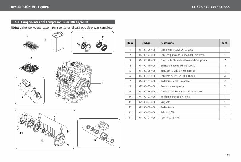
1 014-00195-000 Compresor BOCK FKX40/655K 1
2 014-00197-000 Conj. de Juntas de Sellado del Compresor 1
3 014-00198-000 Conj. de la Placa de Válvula del Compresor 2
4 014-00199-000 Bomba de Aceite del Compresor 1
5 014-00200-000 Junta de Sellado del Compresor 1
6 014-00201-000 Conjunto de Pistón BOCK FKX40 4
7 014-00202-000 Rodamiento del Compresor 2
8 027-00002-000 Aceite del Compresor 2
9 041-00226-000 Conjunto del Embrague del Compresor 1
10 041-00457-000 Kit del Embrague sin Polea 1
11 029-00052-000 Magneto 1
12 029-00008-000 Rodamiento 1
13 014-00097-000 Polea 2A/2B 1
14 017-00104-000 Tornillo M12 x 40 1
CC 305 - CC 335 - CC 355DESCRIPCIÓN DEL EQUIPO
NOTA: visite www.reparts.com para consultar el catálogo de piezas completo.
2.3- Componentes del Compresor BOCK FKX 40/655K
19
1 2 3 4
Sin Renovación Con Renovación
7 131298 10 11
5 6
16
14 15
Ítem Código Descripción Cant.
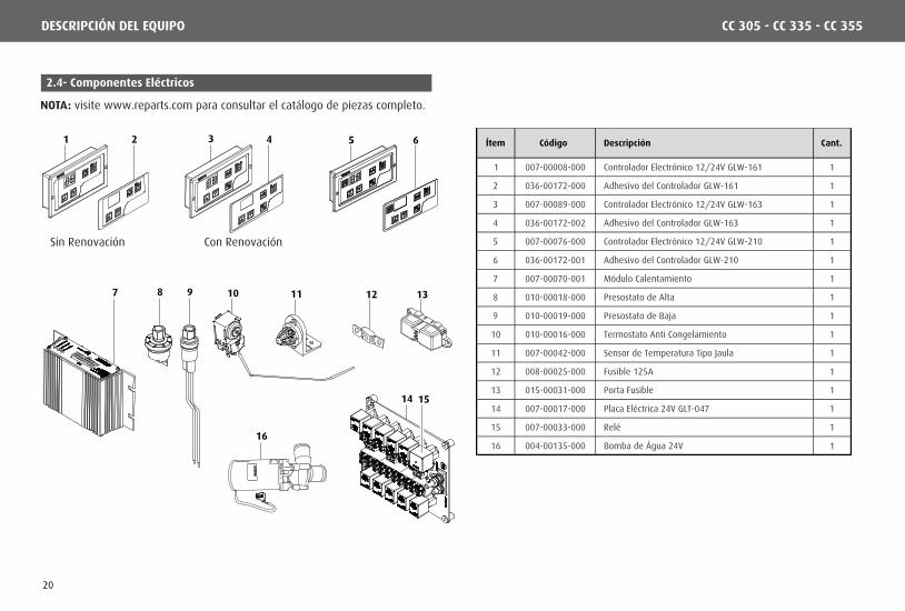
1 007-00008-000 Controlador Electrónico 12/24V GLW-161 1
2 036-00172-000 Adhesivo del Controlador GLW-161 1
3 007-00089-000 Controlador Electrónico 12/24V GLW-163 1
4 036-00172-002 Adhesivo del Controlador GLW-163 1
5 007-00076-000 Controlador Electrónico 12/24V GLW-210 1
6 036-00172-001 Adhesivo del Controlador GLW-210 1
7 007-00070-001 Módulo Calentamiento 1
8 010-00018-000 Presostato de Alta 1
9 010-00019-000 Presostato de Baja 1
10 010-00016-000 Termostato Anti Congelamiento 1
11 007-00042-000 Sensor de Temperatura Tipo Jaula 1
12 008-00025-000 Fusible 125A 1
13 015-00031-000 Porta Fusible 1
14 007-00017-000 Placa Eléctrica 24V GLT-047 1
15 007-00033-000 Relé 1
16 004-00135-000 Bomba de Água 24V 1
CC 305 - CC 335 - CC 355DESCRIPCIÓN DEL EQUIPO
NOTA: visite www.reparts.com para consultar el catálogo de piezas completo.
2.4- Componentes Eléctricos
20

Planta código: 007-00017-000
RENOVACIÓN
RENOVACIÓN
RENOVACIÓN
5
4
123
78
6
9
6,3
REF. AMP 180907-0CONECTOR 2VIAS MACHO TE
1- PERNO 6 (MOTOR)2- PERNO 4 (MOTOR)
2
6,3
TERMINAL HEMBRA
REF. AMP 735432-2P/ CABLES 0,5 aL 2,5mm
2
1
OBSERVACIÓN: como esto es un
equipo eléctrico del control con la
corriente que c on muta del colmo,
es muy importante ser instalado en un
espacio expresado, abierto, lejos del
combustible/de las tuberías materia-
les inflamables, riesgo del fuego/de
la explosión. Este equipo no se protege
contra el agua. Los salpican del agua
pueden dañarla.
4 - EMBRAGUE
1 - EVAP. BAJA 12 - EVAP. BAJA 23 - EVAP. BAJA 3
1 - EVAP. ALTA 1 1 - N.C.2 - EVAP. ALTA 2 2 - TIERRA
FUSIBLES:
F3 - EMBRAGUE - 5A F4 - EVAP. BAJA 1 - 10AF5 - EVAP. BAJA 2 - 10A
F12 - EVAP. BAJA 4 - 10AF13 - EVAP. BAJA 3 - 10AF14 - EVAP. BAJA 5 - 10A
RL2 - EMBRAGUEY
YY
RL3 - EVAP. BAJA 1 Y 2
RL8 - EVAP. BAJA 3 Y 4RL9 - EVAP. BAJA 5 Y 6RL10 - EVAP. ALTA 5 Y 6
RL4 - EVAP. ALTA 3 Y 4RL5 - EVAP. ALTA 1 Y 2
3 - EVAP. ALTA 3 3 - LIGA EVAP. ALTA
9 - EVAP. BAJA 4
8 - EVAP. BAJA 5
7 - EVAP. BAJA 6
9 - EVAP. ALTA 4 9 - N.C.
8 - EVAP. ALTA 5 8 - N.C.
7 - EVAP. ALTA 6 7 - +24V DIR. BATERIA6 - N.C. 6 - N.C. 6 - LIGA COND.5 - N.C. 5 - CORTINA DE AIRE 5 - +24V AP. IGNICIÓN4 - N.C. 4 - N.C. 4 - LIGA EVAP. BAJA
Conector9 Vias hembra
ref. AMP:880125-0
Terminal machop/ cables 0,5-2,5mm2
ref. AMP: 880685-2
CC 305 - CC 335 - CC 355SISTEMA ELÉCTRICO
3- Placa Comando Eléctrico RODOVIÁRIO GL-T047 / 24V
21
GL-W210(V
M/1
,5)
(AZ/1,5)
VM/3
5,0
AZ/
1,5
+ VALT
(MA/1,5)
(VM/1,5)
(LI/1
,5)
(BR
/1,5
)
(PR/1,5)
(LA
/1,5
)
VM/1
,0
AZ/
1,5
+ VALT
(MA/1,5)
(MA/1,5)
(BR/1,0)
(LI/1
,5)
(BR
/1,5
)
(PR/1,5)
(LA
/1,5
)
MA
/1,0
CZ/
1,5
VM/3
5,0
A
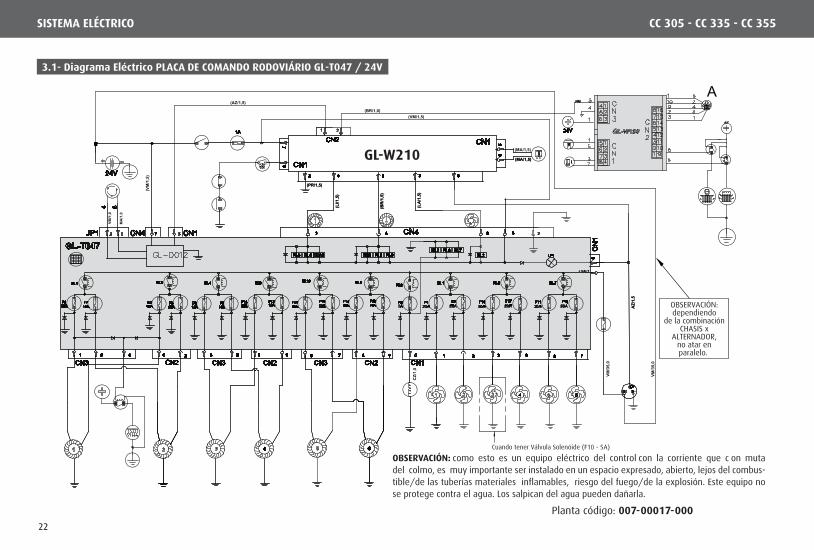
OBSERVACIÓN:dependiendo
de la combinaciónCHASIS x
ALTERNADOR,no atar enparalelo.
Cuando tener Válvula Solenóide (F10 - 5A)
CC 305 - CC 335 - CC 355SISTEMA ELÉCTRICO
Planta código: 007-00017-000
OBSERVACIÓN: como esto es un equipo eléctrico del control con la corriente que c on muta del colmo, es muy importante ser instalado en un espacio expresado, abierto, lejos del combus-tible/de las tuberías materiales inflamables, riesgo del fuego/de la explosión. Este equipo no se protege contra el agua. Los salpican del agua pueden dañarla.
3.1- Diagrama Eléctrico PLACA DE COMANDO RODOVIÁRIO GL-T047 / 24V
22

GL-W163(V
M/1
,5)
(AZ/1,5)M
A/1,
0
VM
/1,0
GL-D012
(BR/1,0)
1
VM
/35,0
AZ/
1,5
+ VALT
(MA/1,5)
(MA/1,5)(VE/1,5)
(LI/1
,5)
(BR
/1,5)
(PR/1,5)
(LA/
1,5)
CI/1
,5
VM
/35,0
AZ/
1,5
+ VALT
(MA/1,5)
(MA/1,5)
(VM/1,5)
(VE/1,5)
(LI/1
,5)
(BR
/1,5)
(PR/1,5)
(LA/
1,5)
2
OBSERVACIÓN:dependiendo
de la combinaciónCHASIS x
ALTERNADOR,no atar enparalelo.
Cuando tener Válvula Solenóide (F10 - 5A)
CC 305 - CC 335 - CC 355SISTEMA ELÉCTRICO
Planta código: 007-00017-000
OBSERVACIÓN: como esto es un equipo eléctrico del control con la corriente que c on muta del colmo, es muy importante ser instalado en un espacio expresado, abierto, lejos del combustible/de las tuberías materiales inflamables, riesgo del fuego/de la explosión. Este equipo no se protege contra el agua. Los salpican del agua pueden dañarla.
3.2- Diagrama Eléctrico PLACA DE COMANDO RODOVIÁRIO GL-T047 / 24V
23

1- Protección Personal:
2- Alta presión: Otros Cuidados:
3- Mangueras:
7- Gas tóxico:
6- Soldadura:
4- Superficies calientes:
5- Componentes en Rotación: 4- Precauciones de Seguridad
R134a
R134a
PSI
30
2010
0
10
20
30
4050
60
70
80
90
100
110
120
-40
-20
0
20
40
6080
100
120
140
160
180
200
R134a
PSI0
50
100
150200
250
300
-30
0
30
60
90
120150
180
210
240
270
300
330
350
Los sistemas de aire acondicionado ofrecen riesgos químicos, mecánicos y eléctricos.Es indispensable que sean utilizados los EPIs (equipos de protección individual), figura 01, para protegerse del gas refrigerante, del aceite de refrigeración, del ácido de batería, de los deshechos lanzados, de las altas temperaturas de los motores y de los ruidos.
El refrigerante en forma líquida y en alta presión representa un riesgo en potencial. El refrigerante liberado para el ambiente puede causar daños serios en los ojos y en la piel.
Los ventiladores, las poleas y las correas pueden no ser percepti-bles bajos ciertas condiciones. Debe ser tomado un cuidado especial al aproximar las manos.
La soldadura debe ser practicada con cautela, pues puede causar quemaduras y producir gases tóxicos.Utilice locales ventilados.
El gas refrigerante en presencia de llamas produce un gas tóxico y puede causar serias irritaciones respiratorias.Cuidado especial en ambientes cerrados, donde la fuga de refrige-rante puede causar falta de aire.
• Al utilizar escaleras y plataformas debe ser tomado cuidado pues pueden resbalar o quebrar.• Utilice cinturón de seguridad siempre que vaya a trabajar en alturas mayores a 1,5 metros.• Nunca aplique calor en recipientes o en líneas presurizadas.• Nunca haga funcionar el equipo con la válvula de servicio de descarga cerrada.• El aceite de refrigeración puede causar irritaciones en la piel y en los ojos, evite el contacto prolongado.• Verifique si todos los tornillos están en el largo cierto y con el apriete correcto.
• Todos los componentes que no estén en perfecto estado de conservación deberán ser sustituidos por motivo de seguridad.
Verifique si las mangueras del manómetro están en condicio-nes de uso y, al utilizarlas, aléjelas de las correas, de las poleas y de las superficies calientes.
La descarga de los compresores, los tubos de escape y otros componentes del motor pueden estar extremamente calientes.
CC 305 - CC 335 - CC 355SEGURIDAD
24
SOSTENIBILIDAD
5- Desecho de Productos
Preocupada con la sostenibilidad Valeo Climatização do Brasil - Veículos Comerciais S/A dirige sus clientes y su red de servicio autorizada al descarte de productos de manera medioambiental correcta y con seguridad.
Destinarse adecuadamente el producto o componentes al fin de su vida útil va a contribuir con la preservación y la disminución de la contaminación del medioambiente, lo que va generar desarrollo económico y sustentable, a través del Programa de Logística Revertida.
De acuerdo con la Leye 12.305/2010, la destinación adecuada ambientalmente, de componentes (piezas, aceite, gas, gaseosa) es obligatoria.
Es responsabilidad de todos asegurar que los productos y componentes sean conducidos para el tratamiento adecuado a las empresas homologadas por los órganos ambientales.
Para más informaciones de nuestro Programa de Logística Revertida consulta nuestro sitio web: http://www.valeo-thermalbus.com/br
CC 305 - CC 335 - CC 355
25

ENG
LISH
26
INTRODUCTION
VALEO Climatização do Brasil - Veículos Comerciais S/A offers a full line of equipment for bus air conditioning systems for vans, micro and midi buses, commuter, articulated, coaches and double-deckers.
Air conditioning system that is modern and high quality, the products of VALEO Climatização do Brasil - Veículos Comerciais S/A have been developed looking for comfort and tranquility to passengers that uses the public transport.
However, you need to take care to assure a good use and operation of the air conditioning system, and then you can obtain a better performance of its technology resources.
It is mandatory to do the preventive and corrective maintenance procedures, they must be accomplished by experts or dully technicians. Looking for improving and updating the refrigeration technical teams, this manual describes the fundamentals of our air conditioning system based on the most important thermodynamic formulas.
You can find operation instructions of VALEO Climatização do Brasil - Veículos Comerciais S/A air conditioning too, besides it advises you to follow technical procedures of adequate preventive maintenance obeying environmental and safety rules.
Frequent training for technical team make them able to get right diagnosis from equipment (appliances) to accomplish the servicing.
correctly with quality and responsibility, assuring to the whole fleet a perfect operation of VALEO Climatização do Brasil - Veículos Comerciais S/A equipment.
CC 305 - CC 335 - CC 355
27
CC 305 - CC 335 - CC 355INDEX
WARRANTY TERMSWarrant Terms.................................................................................................................................................................................................................................................29
PREVENTIVE MAINTENANCEPreventive Maintenance Frequency Check List..................................................................................................................................................................................................................................................30Refrigerant Gas R134a..............................................................................................................................................................................................................................................31Oil................................................................................................................................................................................................................................................................................31Dry Filter.................................................................................................................................................................................................................................................................31Compressor Sealing Part...........................................................................................................................................................................................................................31Ducts...............................................................................................................................................................................................................................................................................31Pulley Belts..............................................................................................................................................................................................................................................................................31
EQUIPMENT IDENTIFICATION (ID)Identification Tag.............................................................................................................................................................................................................................................33
OPERATING THE AIR CONDITIONER1- Operating the Air Conditioner................................................................................................................................................................................................................................................341.1- Controller Operation GL-W163 / GL-W210...............................................................................................................................................................................................................................361.2- Setting the Controller................................................................................................................................................................................................................................................371.3- Reading the Temperature................................................................................................................................................................................................................................................371.4- Programming the SET-POINT....................................................................................................................................................................................................................371.5- Automatic Mode...................................................................................................................................................................................................................................................371.6- Ventilation Mode.......................................................................................................................................................................................................................................................................371.7- Cooling Mode........................................................................................................................................................................................................................................381.8- Heating Mode............................................................................................................................................................................................................................381.9- Heating by Conveyors.........................................................................................................................................................................................................................381.10- Air Refreshening...............................................................................................................................................................................................................................381.11- Internal and External Temperature..................................................................................................................................................................................................381.12- Failures........................................................................................................................................................................................................................................391.13- Control GL-W163 Alarm Failures.......................................................................................................................................................................................................391.14- Control GL-W210 Alarm Failures......................................................................................................................................................................................................39
EQUIPMENT DESCRIPTION2- Technical Data Sheet....................................................................................................................................................................................................................402.1- Evaporator Components.....................................................................................................................................................................................................................412.2- Condenser Components..........................................................................................................................................................................................................................422.3- Compressor Components - BOCK FKX 40/655K..........................................................................................................................................................................................432.4- Electric Components.........................................................................................................................................................................................................................44
ELECTRICAL SYSTEM3- Electric Control Board RODOVIARIO GL-T047 / 24V.....................................................................................................................................................................453.1- Electrical Diagram COMMAND PLATE RODOVIARIO GL-T047 / 24V GL-W210......................................................................................................................................................463.2- Electrical Diagram COMMAND PLATE RODOVIARIO GL-T047 / 24V GL-W163 ...........................................................................................................................47
SAFETY PRECAUTION4- Safety Precaution..................................................................................................................................................................................................................................................................48
SUSTAINABILITY5- Product Discard..................................................................................................................................................................................................................................................................49

WARRANTY TERMS
Warrant Terms
VALEO Climatização do Brasil - Veículos Comerciais S/A warrants its products for one year in accordance with the terms listed below:
1 - The warranty will be valid for the period above specified, counting from thedate when the equipment is installed in keeping with the warrant certificate, even after the property there of has ben transfered.
2 – Should the equipment be installed by a third part, VALEO Climatização do Brasil - Veículos Comerciais S/A warrant only the product and not its instalations.
3 - During the stipulated period, the warranty completely covers the workman-ship and spare parts used to repair defects duly identified as being:premature failure of material and components defects used on its manufacture.
4 - Only a techinician from the VALEO Climatização do Brasil - Veículos Comerciais S/A authorized network of services is qualified to repair the defects coverd under the warranty.
5 - The warranty approval is subject to the technical analysis of the defects shown in the components and operational conditions to which the equipment has been subjected.
6 - No claims will be accepted if the vehicle is still in use after the defect is found, even if there is lack of pieces, delay in transportation or any other such incident.
b) If the product suffers any damage caused by improper use, neglect, accident, failures caused by external agents and even lack of maintenance (see owner's manual) or services performed by unqualified person.
c) If the warranty certificate and/or the serial number of the product are adulterated, overwritten or damaged.
d) If defects or unsatisfactory performance are caused by the use of non originalspare parts and in disagreement with the technical specifications from VALEO Climatização do Brasil - Veículos Comerciais S/A.
8 - The Warranty Does Not Cover
a) Displacement of the bus for repairing of the equipment. In case the customerrequests to be attended in the same place where products is operating, the collection or not of the visitation charge will be the criterion of the authorized service provider.b) The attending to the consumer, free or paid, in cities that do not have authorized services providers. So the expenses with displacement are the sole responsibility of the owner.c) Lack of proper preventive maintenance, as described in the preventive maintenance item in this manual.d) Replacement of bearings, belts, filters in general and lubricating oil, since they are considered items of natural wear.Bearings, belts and alternators have limited warranty as follows:
- Bearings in general = 60,000km or 1 year, whichever occurs sooner. - Belts in general = 20,000km or 3 months, whichever occurs sooner. - Alternators = 1 year with no mileage limit, however, respecting the conditions established in these warranty terms and the manufacturer's technical specifications.
e) Loss or loss of profits caused by the stoppage of the vehicle due to non-operation of the equipment.
7 - The Warrant Loses its Validity
a) If the installation or use of the product is not in accordance with the VALEO Climatização do Brasil - Veículos Comerciais S/A technical recommendations.
CC 305 - CC 335 - CC 355
29
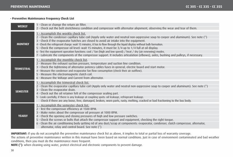
- Preventive Maintenance Frequency Check List
1 - Clean or change the return air filter.2 - Check out the belt stretchiness condition and compressor with alternator alignment, observing the wear and tear of them.
1 - Accomplish the weekly check list.2 - Clean the condenser capillary tube coil (Apply only water and neutral non-aggressive soup to cooper and aluminum). See note (*)3 - Check if the evaporator hatches are closed to avoid air intake into the equipment.4 - Check the refrigerant charge: wait 15 minutes, it has to flow through the liquid display without bulb formation.5 - Check the compressor oil level: wait 15 minutes, it must be 3/4 up to 1/4 full at oil display.6 - Test the equipment operation functions: cool / fan (high and low speed) / heat / dry (air renewing) modes.7 - Lubricate the components of the compressor support. It includes articulation (elbows), axles, bushing and pulleys, if necessary.
1 - Accomplish the monthly check list.2 - Measure the exhaust suction pressure, temperature and suction line condition.3 - Check the tightening of alternator potency cables fuses in general, electric board and start motor.4 - Measure the condenser and evaporator fan flow consumption (check their air outflow).5 - Measure the electromagnetic clutch coil.6 - Measure the Voltage and Current from alternator.
1 - Accomplish the trimestral check list.2 - Clean the evaporator capillary tube coil (Apply only water and neutral non-aggressive soup to cooper and aluminum). See note (*)3 - Clean the evaporator drain.4 - Check out the oil retainer felt of the compressor sealing part.5 - Look carefully, if there is any leakage at coupling spots: oil leakage, refrigerant leakage.
Check if there are any loose, free, damaged, broken, worn parts, rusty, melting, cracked or bad fractioning to the bus body.
1 - Accomplish the semester check list.2 - Test the compressor efficiency at 1500 RPM.3 - Make notes about the compressor oil pressure at 1000 RPM.4 - Check the opening and closing pressures of high and low pressure switches.5 - Check the screws or bolts that attach the compressor support and equipment, checking the right torque.6 - Clean the air conditioning body getting rid of any dust/scrap at components: evaporator, condenser, clutch compressor, alternator, relay and control board. alternator, relay and control board. See note (*)
WEEKLY
TRIMESTRAL
SEMESTER
YEARLY
MONTHLY
IMPORTANT: If you do not accomplish the preventive maintenance check list as above, it implies to total or partial loss of warranty coverage.The actions of preventive maintenance written in this manual have been based on normal conditions. Just in case of environment contaminated and bad weather conditions, then you must do the maintenance more frequent.NOTE (*): when cleaning using water, protect electrical and electronic components to prevent damage.
PREVENTIVE MAINTENANCE CC 305 - CC 335 - CC 355
30

SAY NO TO RECONDITIONED PARTS
ATTENTION: under no circumstances, refrigerant cannot be spoiled at theatmosphere.
PREVENTIVE MAINTENANCE
- Refrigerant Gas R134a
VALEO Climatização do Brasil - Veículos Comerciais S/A products apply for R 134a. The se of different type of gas, low quality or from unknown brands will cause low performance from the refrigeration and damage the equipment components.
- Ducts
The cleaning of the air ducts must be done every tree months, it can be earlier, depending on: the frequency of operation of the air conditioning system, quantity of passengers and resistivity of the environment where it is driven. This cleaning is the responsibility of the vehicle owner´s only, he is in charge of this cleaning in order to offer good air quality to his passengers.
NOTE: ducts are components of the bus body.
- Pulley Belts
In order to increase the lifetime of the belts, the strength/stretchiness must be as low as possible, but working, not leaving them skidding without any friction.Too low stretchiness on the pulley belts can cause overheat and too much skidding, causing early break.Too much stretched belts diminish their lifetime and from roll bearing and from sleeves, this problem can cause engine interior and compressor damage.After changing the belts, check their stretchiness back again after 48 working hours.It is recommended not use different brands. Install assemblies with the same diameter/length of the series and do not apply new belts beside old ones. Putting the assembly into action without one or two belts for a long time can cause a damage inside the “v” groove of the pulley. It will cause wear in that “v” groove, so the new belt may not be stretched accordingly.
The application of reconditioned parts will diminish the air conditioning efficiency, will overcharge the electric system causing early brake of the compressor and set a fire!
- Oil
We recommend you that you shall preventively change the air system oil every two years or 10.000 working hours, whatever becomes first.
- Dry Filter
We recommend that you shall preventively change the drier filter every 3 years. Just in case, you need to refill in the equipment with gas, we recommend you replace to a new filter to extinguish any dirt out of the system.
- Compressor Sealing Part
In order to avoid leakage at the sealing part of the compressor due to lack of lubrication, then the air conditioning must be working at cool mode for at least 15 minutes, once every 15 days.The sealing part is lubricated by the compressor oil and in its normal operation allows a small leakage of 0.05 ml per hour under operation.Check frequently the reservoir and/or felt then remove the excess of it.Dispose the old oil as your Country regulations and laws.
CC 305 - CC 335 - CC 355
31

The following items are in charge of the OEM Plant (Bus Body Builder).
Problems with any driver´s air conditioning component, leakage, bad working or operation.
IMPORTANT: clean the return filter of the driver´s air conditioning, at least, once a week.
Bad attachment.
Leakage at connections and welding points.
Damages due to frictioning / chassis and components frictioning or bad installed.
Excess or lack of torque at attaching screws/bolts.
Assembly is out of project designs.
Pulleys are not aligned, excess or lack of stretchiness at the belts and pulleys.
Leakage test procedure.
Vacuum process and refrigerant gas charge.
Driver´sEvaporator
Tubes, hoses,
drains and wiring harness
Alternator / Compressor
Support
Gas ChargeProcess
CC 305 - CC 335 - CC 355
Note: In case the installation is bad, VALEO Agent Authorized Service Net will have to call the OEM Plant first, then get an authorization to do the service,print and issue the Invoice of repairs.
ATTENTION: Just in case a problem happens in the refrigeration system, then it must be repaired in an authorized shop or qualified professional.If a third party installs the equipment, VALEO Climatização do Brasil - Veículos Comerciais S/A, guarantees only the product, not the installation of it.
IMPORTANT: the vehicle owner must do preventive maintenance actions. If you do not do the preventive maintenanceas described in this chapter, it implies you lose partially or full warranty coverage.
PREVENTIVE MAINTENANCE
32
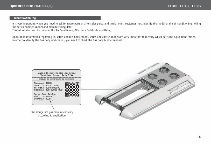
- Identification Tag
It is very important, when you need to ask for spare parts or after sales parts, and similar ones, customer must identify the model of the air conditioning, tellingthe series number, model and manufacturing date.This information can be found in the Air Conditioning Warranty Certificate and ID tag.
Application information regarding to: series and bus body model, series and chassis model are very important to identify which parts the equipment carries.In order to identify the bus body and chassis, you need to check the bus body builder manual.
the refrigerant gas amount can varyaccording to application.
CC 305 - CC 335 - CC 355EQUIPMENT IDENTIFICATION (ID)
33
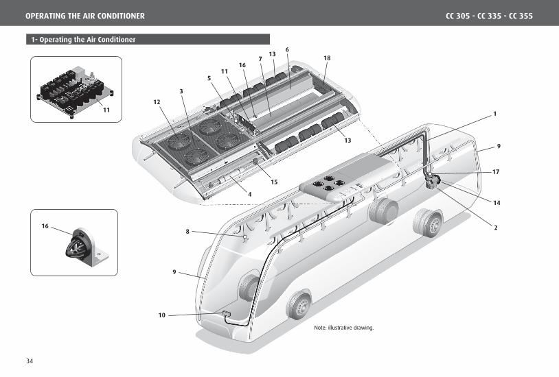
Note: illustrative drawing.
17
14
28
1
167
15
6
13
11
13
5
4
3
12
18
9
9
10
16
11
CC 305 - CC 335 - CC 355OPERATING THE AIR CONDITIONER
1- Operating the Air Conditioner
34

Condenser FanCondenser fan and the compressor will only work at “Cool Mode”.
Refrigerant Fluid
Its main goal is dissipate the heat out, which was absorbed by the refrigerant fluid along the refrigeration system. At the condenser, the overheat refrigerant fluid is sent to outside losing its force, changing from gaseous state to liquid state.
Condenser
Drier filterTiene la finalidad de retener impurezas y/o humedad que pueda haber en el sistema impidiendo que lleguen en la válvula de expansión.
Valve hinders the refrigerant inlet that comes from de condenser at high pressure and its goal is adjust the refrigerant gas flow that passed by the evaporator looking for making the pressure steady and temperature at the capillary tubes output.
CompressorWhen it is working, the compressor sucks the refrigerant fluid from evaporator at gaseous state and under low pressure, compressing it, so temperature and pressure increase, then the compressor puts it into the condenser.
MEC
HA
NIC
SYS
TEM
Compressor OperationIt is started up by the vehicle engine though a pulley-and-belt system and put into action by an electromagnetic clutch when air conditioning is operating at “Cool Mode”.
Air refrechmentThis permits the entry of the exernal in order to expelunwanted odors and impurities from the vehicle.
Evaporator FanEvaporator fans are working at cool and fan modes, fans can be set in two speeds. Sped control can be manual or automatic.
Temperature SensorThe interior temperature is measured by the temperature sensor placed at the air return spot.
Pressure SwitchesPressure switches are electric devices that monitor the air conditioning equipment operation pressure. Every time a strong change happens from the NORMAL temperature, they turn off the compressor immediately to avoid break.Observation: pressures are always monitored, even if the air conditioning is turned off.
ELEC
TRIC
SYS
TEM
EvaporatorsNow at evaporators, the refrigerant fluid, at low pressure, turns from l iquid to gaseous state, absorbing the interior heat of the vehicle in this process.
ControllerIt is installed in the instrument panel, it offers to the driver to set-point of temperature, to see by display the interior temperature, offering full climatic control inside de bus.Set-point: it is the temperature the driver wishes to set inside the vehicle for passengers.
Relay BoardRelay board has the controller controls, condenser fan control, evaporator control and compressor control.
Air filterAir return filter retains impurities from air avoiding any block of dirt at evaporator capillary tubes and coil.
Air circulationAir being cooled by the evaporator, then it follows to the bus interior through fans.
DrainIt is a way to get the condensed moisture from evaporator tubes from the condensed tray to putting out.
MEC
HA
NIC
SYS
TEM
ELEC
TRIC
SYS
TEM
1
2
3
4
5 Expansion Thermostatic Valve
6
7
8
9
10
11
18
12
13
14
16
Solenoid Valve15
17
Solenoid valve is applied to stop refrigerant flow through a line. It is a closing valve controlled remotely and under electric operation.
CC 305 - CC 335 - CC 355AIR CONDITIONING OPERATION
It is inside the air conditioning equipment, inside the system. It works absorbing the heat from the interior / room of the vehicle, at the evaporator, and then it goes to the condenser where the heat is thrown to the outside. VALEO Climatização do Brasil - Veículos Comerciais S/A, products apply refrigerant R134a, according to the Protection Environmental Law.
35

1.1- Controller Operation GL-W163 / GL-W210
1 - Numeric display.
2 - Automatic control key cooling / heating (AUTO).
3 - Ventilation control key (VENT.).
4 - Air-refreshment control key (RENOV.).
5 - Key (INCREASE).
6 - Key (DECREASE).
7 - Indicator "cooling mode/heating mode’’.
8 - Indicator "automatic mode’’.
9 - Indicator "low-speed ventilation mode’’.
10 - Indicator "high-speed ventilation mode".
11 - Indicator "air- refreshment mode’’.
12 - Internal / external temperature check key (TEMP.).
13 - Indicator "Internal / external temperature check key".
GL-W163 CONTROLLER GL-W210 CONTROLLER
CC 305 - CC 335 - CC 355OPERATING THE AIR CONDITIONER
1
3
8
4
11 2 7
5 6
9 10 1312
3
8
4
11 2 7
5 6
9 101
36

1.6- Ventilation Mode
1.3- Reading the Temperature
1.2- Setting the Controller
1.4- Programming the SET-POINT
1.5- Automatic Mode
The control will turn on when the bus's ignition is started.
The display will first show the control's version of software and after that will show the inside temperature of the bus.
Before the engine starts, the display will show the alarm code for monitoring the operation of the alternator (see item 1.13).
The control monitors the temperature sensors, which are arranged in the vehicle as described below:
a) Internal temperature sensor: Located in the returning-air part of the air-conditioning equipment. b) External temperature sensor *: Located outside of the air-conditioning equipment. c) Duct temperature sensor *: Located in the air ducts.
* Only applies to units that have a ‘heating mode’.
1 – To adjust the set-point, press on the keys (INCREASE) or (DECREASE).The set-point temperature will then flash on the display.
2 – To program the set-point, simply press the key (INCREASE) to increase the temperature or the key (DECREASE) to decrease the temperature until the desired temperature is found.
3 – After the desired temperature has been selected, the display will keep flashing for 5 seconds. When it stops flashing, it will show the new temperature of the inside of the vehicle and the set-point temperature is now reprogrammed.
1 – To select the automatic mode, press the key (AUTO).
In the ‘automatic mode’, the controller will select automatically one of the available functions (cooling or heating) searching for the best possible climate condition in keeping with the set-point temperature.
2 - To disable the 'automatic mode’, press once again the key (AUTO).
The ventilation mode provides two operating speeds:
1 – With ‘automatic mode’ disabled, press the key (VENT) and the ‘ventilation mode’ will start to operate at a low speed. The indicator (10) will be on to display this mode.
2 – To select high speed, press once again the key (VENT). The indicator (11) will be turned on to display this function.
3 – To turn the ‘ventilation mode’ off, press the key (VENT) one more time. When the ‘automatic mode’ is on, the ventilation speed is usually automatic and this will be displayed by the indicator (9). However, ventilation speeds can be also altered manually following the same steps described above.
4 – To restore the ‘automatic mode’, press the key (VENT) until the indicator (9) turns on. This indicates that ventilation is in ‘automatic mode’.
CC 305 - CC 335 - CC 355OPERATING THE AIR CONDITIONER
1.6- Modo Ventilação
37

1.9- Heating by Conveyors *
1.10- Air Refreshening
1.11- Internal and External Temperature
1.8- Heating Mode
1.7- Cooling Mode
After selecting the ‘automatic mode’ according to item 1.5 and if the internal temperature of the vehicle is above the set-point, the equipment will start to operate in ‘cooling mode’ automatically.
Whenever the system starts up in ‘cooling mode’ the evaporator fans will start on ‘automatic mode’. However, the ventilation speeds may be changed manually (see item 1.6).
Note: in the ‘automatic mode’, the evaporator blowers are activated according to the set-point programmed.
1 – After selecting the ‘automatic mode’ according to item 1.5, and if the internal temperature of the vehicle is below set-point, the equipment will begin operating in 'roof-heating mode'.
Note: in this mode, the ventilation will operate only at low speed.
The ‘heating by conveyors mode’ is activated in the same way as the ‘roof-heating mode’.
* Conveyors – Heating coils installed by the body manufacturers. The are normally located along the side of the passengers' saloon, below the seat.
1 – With the air conditioner running on ‘automatic mode’, the air-refreshening will work according to the set-point temperature so as to find a comfortable condition for passengers.
This applies to both ‘cooling mode’ and ‘heating mode’.
a) The indicator (11) will turn on to inform when the air-refreshener is open and turn off to show that it is closed.2 – During cooling or heating, the air-refreshener can be manually activated by pressing the key (RENOV). It will stay open for 10 seconds. After this, it will close automatically and go back to the automatic cycle.
Note: in the event of the air-refreshener being open when the ‘cooling mode’ starts operating, it will shut automatically.
The display will normally show the inside temperature of the bus.
1 – To verify the external temperature, press the key (TEMP). The display will then show the outside temperature for 5 seconds. While the external temperature is shown on the display, the indicator (13) will be on.
After 5 seconds the display will go back to showing the internal temperature and the indicator (13) will be off.
If the key (TEMP) is pressed before the pre-determined period of 5 seconds, the display will show the internal temperature again.
CC 305 - CC 335 - CC 355OPERATING THE AIR CONDITIONER
38

1.12- Failures
Air return sensor failure
Duct sensor failure
External sensor failure
Pressure Switch failure
Communication failure
Valve connection failure
1.13- Control GL-W163 Alarm Failures
1.14- Control GL-210 Alarm Failures
FAILURE DESCRIPTION
Alternator failure
FAILURE DESCRIPTION
Pressure switch failure
Temperature sensor open
Temperature sensor in short circuit
Alternator failure
When any failure occurs in the air conditioning system, the display will show a message as shown below.
IMPORTANT: whenever a failure in the air-conditioner system is detected,the vehicle must be sent to a VALEO Climatização do Brasil - Veículos Comerciais S/A authorized service station.
1 - If any failure occurs to the pressure switch, the display will show the message (HA) and the system will turn the compressor off. The control will wait for 3 minutes before turning the compressor on again, once the failure has been corrected.
2 - As the system operates according to the internal temperature, the control has two failure codes to monitor the temperature sensor: a) If the temperature sensor is open, the display will show (OP). b) If the temperature sensor is short circuit, the display will show (SC).
3 - This control has a parameter for monitoring the alternator. In case of failure to the alternator, the display will show (AL).
1 - This control has a parameter for monitoring the alternator. In case of failure to the alternator, the display will show (AL). However, the control outlets will continue to be on.
2 - In case of failure to the air-return sensor, the display will show (FI).
3 - In case of failure to the air-duct sensor, the display will show (F3).
4 - In case of failure to the external sensor, the display will show (F5).
5 - If pressure failure occurs, the display will show the message (FP) and the system will turn the compressor off. The system then will wait 3 minutes before turning the compressor on againg, once the failure has been corrected.
6 - In case of communication failure the display shows (FC) and function only in cooling mode.
7 - In case the valve connection for heating system fails, the display will show (EI).
CC 305 - CC 335 - CC 355OPERATING THE AIR CONDITIONER
39
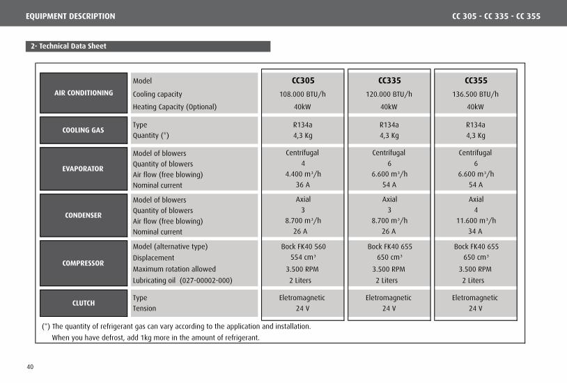
2- Technical Data Sheet
Model CC305 CC335 CC355
Cooling capacity 108.000 BTU/h 120.000 BTU/h 136.500 BTU/h
Heating Capacity (Optional) 40kW 40kW 40kW
Type R134a R134a R134a
Quantity (*) 4,3 Kg 4,3 Kg 4,3 Kg
Model of blowers Centrífugal Centrífugal Centrífugal
Quantity of blowers 4 6 6
Air flow (free blowing) 4.400 m³/h 6.600 m³/h 6.600 m³/h
Nominal current 36 A 54 A 54 A
Model of blowers Axial Axial Axial
Quantity of blowers 3 3 4
Air flow (free blowing) 8.700 m³/h 8.700 m³/h 11.600 m³/h
Nominal current 26 A 26 A 34 A
Model (alternative type) Bock FK40 560 Bock FK40 655 Bock FK40 655
Displacement 554 cm³ 650 cm³ 650 cm³Maximum rotation allowed 3.500 RPM 3.500 RPM 3.500 RPM
Lubricating oil (027-00002-000) 2 Liters 2 Liters 2 Liters
Type Eletromagnetic Eletromagnetic Eletromagnetic
Tension 24 V 24 V 24 V
(*) The quantity of refrigerant gas can vary according to the application and installation.
When you have defrost, add 1kg more in the amount of refrigerant.
CONDENSER
CLUTCH
AIR CONDITIONING
COOLING GAS
EVAPORATOR
COMPRESSOR
CC 305 - CC 335 - CC 355EQUIPMENT DESCRIPTION
40

2.1- Evaporator Components
7
7
4
3
6
11
12
13
8
510
9
21
NOTE: visit www.reparts.com to consult the complet parts catalog.
Item Code Description Qty.
006-00134-005 Left Evaporator Coil - CC355 1
006-00138-001 Left Evaporator Coil - CC305 / 335 1
006-00135-005 Right Evaporator Coil - CC355 1
006-00139-001 Right Evaporator Coil - CC305 / 335 1
3 006-00152-001 Right Heating Coil 1
4 006-00153-001 Left Heating Coil 1
5 012-00055-000 Hot Water Valve - Optional 1
6 012-00081-000 Expansion Valve 2
7 021-00014-000 Radial Fan 24V - with Carbon Brush Variable
8 022-00010-000 24V Air Renewal Motor - Optional 1
9 031-00573-000 Liquid Line Tube Set with Defroster 1
10 031-00590-000 Evaporator Suction Tube Set 1
11 034-00367-001 Left Condenser / Evaporator Cover 1
12 034-00368-001 Right Condenser / Evaporator Cover 1
13 041-01445-000 Air Renewal Set - Optional 1
1
2
CC 305 - CC 335 - CC 355EQUIPMENT DESCRIPTION
41

2.2- Condenser Components
1
3
Item Code Description Qty.
1 006-00134-005 MPHE Condenser Coil 1
2 006-00135-005 Maintenance Rod 2
3 006-00152-001 Axial Fan 24V - with Carbon Brush Variable
4 006-00153-001 Liquid Tank / Dryer Filter / Display 1
5 012-00055-000 Tank Tube Set X Evaporator Tubing 1
6 012-00081-000 MPHE Tank Coil Tube Set 1
CC 305 - CC 335 - CC 355EQUIPMENT DESCRIPTION
NOTE: visit www.reparts.com to consult the complet parts catalog.
2
5
46
42

2.3- Compressor Components - BOCK FKX 40/655K
1
2
3
84 7
6
10 9
1314
12
11
5
Item Code Description Qty.
1 014-00195-000 BOCK FKX40/655K Compressor 1
2 014-00197-000 Compressor Sealing Gaskets Set 1
3 014-00198-000 Compressor Valve Board Set 2
4 014-00199-000 Compressor Oil Pump 1
5 014-00200-000 Compressor Sealing Kit 1
6 014-00201-000 BOCK FKX40 Piston Assembly 4
7 014-00202-000 Compressor Roll Bearing 2
8 027-00002-000 Compressor Oil 2
9 041-00226-000 Compressor Clutch Assembly 1
10 041-00457-000 Clutch Kit without Pulley 1
11 029-00052-000 Magneto 1
12 029-00008-000 Ball Roller Bearing 1
13 014-00097-000 Pulley 2A/2B 1
14 017-00104-000 Bolt M12 x 40 1
CC 305 - CC 335 - CC 355EQUIPMENT DESCRIPTION
NOTE: visit www.reparts.com to consult the complet parts catalog.
43

2.4- Electric Components
1 2 3 4
Without Renewall With Renewall
7 131298 10 11
5 6
16
14 15
Item Code Description Qty.
1 007-00008-000 12/24V GLW-161 Electronic Controller 1
2 036-00172-000 GLW-161 Controller Adhesive 1
3 007-00089-000 12/24V GLW-163 Electronic Controller 1
4 036-00172-002 GLW-163 Controller Adhesive 1
5 007-00076-000 12/24V GLW-210 Electronic Controller 1
6 036-00172-001 GLW-210 Controller Adhesive 1
7 007-00070-001 Heating Module 1
8 010-00018-000 High Pressure Switch 1
9 010-00019-000 Low Pressure Switch 1
10 010-00016-000 Antifreezing Thermostat 1
11 007-00042-000 Temperature Sensor - Cage Type 1
12 008-00025-000 Fuse 125A 1
13 015-00031-000 Fuse Compartment 1
14 007-00017-000 24V GLT-047 Electric Board 1
15 007-00033-000 Relay 1
16 004-00135-000 Water Pump 24V 1
CC 305 - CC 335 - CC 355EQUIPMENT DESCRIPTION
NOTE: visit www.reparts.com to consult the complet parts catalog.
44
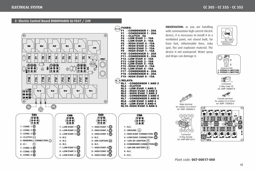
3- Electric Control Board RODOVIARIO GL-T047 / 24V
Plant code: 007-00017-000
RENOVACIÓN
CONTROLLERRENEWALL
1- PERNO 6 (MOTOR)2- PERNO 4 (MOTOR)
OBSERVATION: as you are handling
with commutation high current electric
device, it is necessary to install it in a
ventilated point, not closed built, far
from fuel, inflammable lines, risky
spot, fire and explosion material. The
device is not waterproof. Water spray
and drops can damage it.
4 - CLUTCH
6 - D +
1 - COND. 1
2 - COND. 23 - COND. 3
7 - COND. 6
8 - COND. 59 - COND. 4
5 - RENEWALL CONNECTION
1 - LOW EVAP. 12 - LOW EVAP. 23 - LOW EVAP. 3
1 - HIGH EVAP. 1 1 - N.C.2 - HIGH EVAP. 2 2 - GROUND
FUSES:
RELAYS:
F3 - CLUTCH - 5A F4 - LOW EVAP. 1 - 10A
F1 - CONDENSER 1 - 20AF1 - CONDENSER 1 - 20A
F5 - LOW EVAP. 2 - 10AF6 - HIGH EVAP. 4 - 15AF7 - HIGH EVAP. 2 - 15AF8 - HIGH EVAP. 3 - 15AF9 - HIGH EVAP. 1 - 15AF10 - CONDENSER 3 - 20AF11 - CONDENSER 5 - 20A
F17 - CONDENSER 4 - 20AF18 - CONDENSER 6 - 20A
F12 - LOW EVAP. 4 - 10AF13 - LOW EVAP. 3 - 10AF14 - LOW EVAP. 5 - 10A
F16 - LOW EVAP. 6 - 10AF15 - HIGH EVAP. 5 - 15A
F19 - HIGH EVAP. 6 - 15A
RL2 - CLUTCHRL1 - CONDENSER 1 AND 2
RL6 - CONDENSER 3 AND 4RL7 - CONDENSER 5 AND 6
RL3 - LOW EVAP. 1 AND 2
RL8 - LOW EVAP. 3 AND 4RL9 - LOW EVAP. 5 AND 6RL10- HIGH EVAP. 5 AND 6
RL4 - HIGH EVAP. 3 AND 4RL5 - HIGH EVAP. 1 AND 2
3 - HIGH EVAP. 3 3 - HIGH EVAP. CONNECTION
9 - LOW EVAP. 4
8 - LOW EVAP. 5
7 - LOW EVAP. 6
9 - HIGH EVAP. 4 9 - N.C.
8 - HIGH EVAP. 5 8 - N.C.
7 - HIGH EVAP. 6 7 - +24V DIR. BATTERY6 - N.C. 6 - N.C. 6 - CONDENSER CONNECTION5 - N.C. 5 - AIR CURTAIN 5 - +24V AP. IGNITION4 - N.C. 4 - N.C. 4 - LOW EVAP. CONNECTION
Male terminalfor cables 0,5-2,5mm2
ref. AMP: 880685-2
Connector9 Way female
ref. AMP:880125-0
3
6
2 1 5
4789
6,32
1
Connector2 Way male TE
ref. AMP:180907-0
6,3
Female terminalfor cables 0,5-2,5mm2
ref. AMP: 735432-2
CC 305 - CC 335 - CC 355ELECTRICAL SYSTEM
45

GL-W210(V
M/1
,5)
(AZ/1,5)
VM/3
5,0
AZ/
1,5
+ VALT
(MA/1,5)
(VM/1,5)
(LI/1
,5)
(BR
/1,5
)
(PR/1,5)
(LA
/1,5
)
VM/1
,0
AZ/
1,5
+ VALT
(MA/1,5)
(MA/1,5)
(BR/1,0)
(LI/1
,5)
(BR
/1,5
)
(PR/1,5)
(LA
/1,5
)
MA
/1,0
CZ/
1,5
VM/3
5,0
A
When there is a Solenoid Valve (F10 - 5A)
OBSERVATION:Depending on
the combinationCHASSIS x
A LTERNATOR,do not connect
in parallel.
CC 305 - CC 335 - CC 355ELECTRICAL SYSTEM
Plant code: 007-00017-000
OBSERVATION: as you are handling with commutation high current electric device, it is necessary
to install it in a ventilated point, not closed built, far from fuel, inflammable lines, risky spot, fire
and explosion material. The device is not waterproof. Water spray and drops can damage it.
3.1- Electrical Diagram COMMAND PLATE RODOVIARIO GL-T047 / 24V
46

GL-W163(V
M/1
,5)
(AZ/1,5)M
A/1,
0
VM
/1,0
GL-D012
(BR/1,0)
1
VM
/35,0
AZ/
1,5
+ VALT
(MA/1,5)
(MA/1,5)(VE/1,5)
(LI/1
,5)
(BR
/1,5)
(PR/1,5)
(LA/
1,5)
CI/1
,5
VM
/35,0
AZ/
1,5
+ VALT
(MA/1,5)
(MA/1,5)
(VM/1,5)
(VE/1,5)
(LI/1
,5)
(BR
/1,5)
(PR/1,5)
(LA/
1,5)
2
When there is a Solenoid Valve (F10 - 5A)
OBSERVATION:Depending on
the combinationCHASSIS x
A LTERNATOR,do not connect
in parallel.
CC 305 - CC 335 - CC 355ELECTRICAL SYSTEM
Plant code: 007-00017-000
OBSERVATION: as you are handling with commutation high current electric device, it is necessary
to install it in a ventilated point, not closed built, far from fuel, inflammable lines, risky spot, fire
and explosion material. The device is not waterproof. Water spray and drops can damage it.
3.2- Electrical Diagram COMMAND PLATE RODOVIARIO GL-T047 / 24V
47
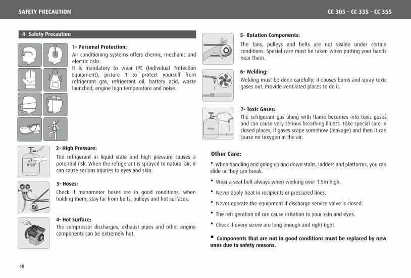
1- Personal Protection:
2- High Pressure: Other Care:
3- Hoses:
7- Toxic Gases:
6- Welding:
4- Hot Surface:
5- Rotation Components: 4- Safety Precaution
R134a
R134a
PSI
30
2010
0
10
20
30
4050
60
70
80
90
100
110
120
-40
-20
0
20
40
6080
100
120
140
160
180
200
R134a
PSI0
50
100
150200
250
300
-30
0
30
60
90
120150
180
210
240
270
300
330
350
CC 305 - CC 335 - CC 355
Air conditioning systems offers chemic, mechanic and electric risks.It is mandatory to wear IPE (Individual Protection Equipment), picture 1 to protect yourself from refrigerant gas, refrigerant oil, battery acid, waste launched, engine high temperature and noise.
The refrigerant in liquid state and high pressure causes a potential risk. When the refrigerant is sprayed to natural air, it can cause serious injuries to eyes and skin.
Check if manometer hoses are in good conditions, when holding them; stay far from belts, pulleys and hot surfaces.
The compressor discharges, exhaust pipes and other engine components can be extremely hot.
The fans, pulleys and belts are not visible under certain conditions. Special care must be taken when putting your hands near them.
Welding must be done carefully; it causes burns and spray toxic gases out. Provide ventilated places to do it.
The refrigerant gas along with flame becomes into toxic gases and can cause very serious breathing illness. Take special care in closed places, if gases scape somehow (leakage) and then it can cause no toxygen in the air.
• When handling and going up and down stairs, ladders and platforms, you can slide or they can break.
• Wear a seat belt always when working over 1.5m high.
• Never apply heat in recipients or pressured lines.
• Never operate the equipment if discharge service valve is closed.
• The refrigeration oil can cause irritation to your skin and eyes.
• Check if every screw are long enough and right tight.
• Components that are not in good conditions must be replaced by new ones due to safety reasons.
SAFETY PRECAUTION
48

SUSTAINABILITY
5- Product Discard
Concerned about sustainability at Valeo Climatização do Brasil - Veículos Comerciais S/A guides its customers and its authorized service network to discard products in an environmentally sound and safe manner.
Proper disposal of the product or components at the end of their useful life will contribute with the preservation and pollutinon reduction of the environment, creating economic growth through the Reverse Logistics Program.
According to Law 12,305 / 2010, the environmentally adequate destination of components (parts, oil, refrigerant) is required.
It is the responsibility of all to ensure that products and components are sent to appropriate treatment to companies approved by the environmental agencies.
For more information about our Reverse Logistics Program, please see our website: http://www.valeo-thermalbus.com/br
CC 305 - CC 335 - CC 355
49

Valeo Climatização do Brasil - Veículos Comerciais S/AAv. Rio Branco, 4688 - Bairro São Cristóvão - CEP 95060-145 | Caxias do Sul - RS - Brasil | Tel. +55 (54) 2101.5700www.valeo-thermalbus.com/br