Manual+de+Servi%e7o+ +Kdl 32cx525 Kdl 40cx525 Kdl 46cx525+Br+Chassis+Az2 f
64
MANUAL DE SERVIÇO TV digital com tela de cristal líquido AZ2-F Chassis Segmento: P-2 9-888-415-01 Version Date Subject 1.0 3/14/2011 Nenhuma revisão ou atualização aplicavel neste momento. DATA DE PUBLICAÇÃO DO ORIGINAL: 3/2011 INFORMAÇÕES DO HISTÓRICO DESTE MANUAL:
Transcript of Manual+de+Servi%e7o+ +Kdl 32cx525 Kdl 40cx525 Kdl 46cx525+Br+Chassis+Az2 f
MANUAL DE SERVIÇO
TV digital com tela de cristal líquido
AZ2-F ChassisSegmento: P-2
9-888-415-01
Version Date Subject1.0 3/14/2011 Nenhuma revisão ou atualização aplicavel neste momento.
DATA DE PUBLICAÇÃO DO ORIGINAL: 3/2011
INFORMAÇÕES DO HISTÓRICO DESTE MANUAL:
MANUAL DE SERVIÇO
TV digital com tela de cristal líquido
AZ2-F ChassisSegmento: P-2
9-888-415-01
Self DiagnosisSupported model
KDL-40CX525
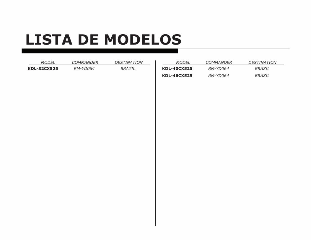
LISTA DE MODELOS MODEL COMMANDER DESTINATION MODEL COMMANDER DESTINATION
KDL-32CX525 RM-YD064 BRAZIL KDL-40CX525 RM-YD064 BRAZIL
KDL-46CX525 RM-YD064 BRAZIL
KDL-32CX525/40CX525/46CX525 i
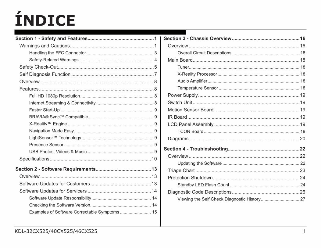
ÍNDICESection 1 - Safety and Features.................................................1
Warnings and Cautions ..............................................................1
Handling the FFC Connector ...................................................... 3
Safety-Related Warnings ............................................................ 4
Safety Check-Out .......................................................................5
Self Diagnosis Function .............................................................7
Overview ....................................................................................8
Features .....................................................................................8
Full HD 1080p Resolution ........................................................... 8
Internet Streaming & Connectivity .............................................. 8
Faster Start-Up ........................................................................... 9
BRAVIA® Sync™ Compatible .................................................... 9
X-Reality™ Engine ..................................................................... 9
Navigation Made Easy ................................................................ 9
LightSensor™ Technology .......................................................... 9
Presence Sensor ........................................................................ 9
USB Photos, Videos & Music ..................................................... 9
!"#$%&$'(%)*+ ...........................................................................10
Section 2 - Software Requirements.........................................13
Overview ..................................................................................13
Software Updates for Customers .............................................13
Software Updates for Servicers ...............................................14
Software Update Responsibility ................................................ 14
Checking the Software Version ................................................. 14
Examples of Software Correctable Symptoms ......................... 15
Section 3 - Chassis Overview ..................................................16
Overview ..................................................................................16
Overall Circuit Descriptions ...................................................... 18
Main Board ...............................................................................18
Tuner... ...................................................................................... 18
X-Reality Processor .................................................................. 18
,-.%)/,0"1% .......................................................................... 18
Temperature Sensor ................................................................. 18
Power Supply ...........................................................................19
Switch Unit ...............................................................................19
Motion Sensor Board ...............................................................19
IR Board ...................................................................................19
LCD Panel Assembly ...............................................................19
TCON Board ............................................................................. 19
Diagrams ..................................................................................20
Section 4 - Troubleshooting .....................................................22
Overview ..................................................................................22
Updating the Software .............................................................. 22
Triage Chart .............................................................................23
Protection Shutdown ................................................................24
Standby LED Flash Count ........................................................ 24
Diagnostic Code Descriptions ..................................................26
Viewing the Self Check Diagnostic History ............................... 27
KDL-32CX525/40CX525/46CX525 ii
ÍNDICE
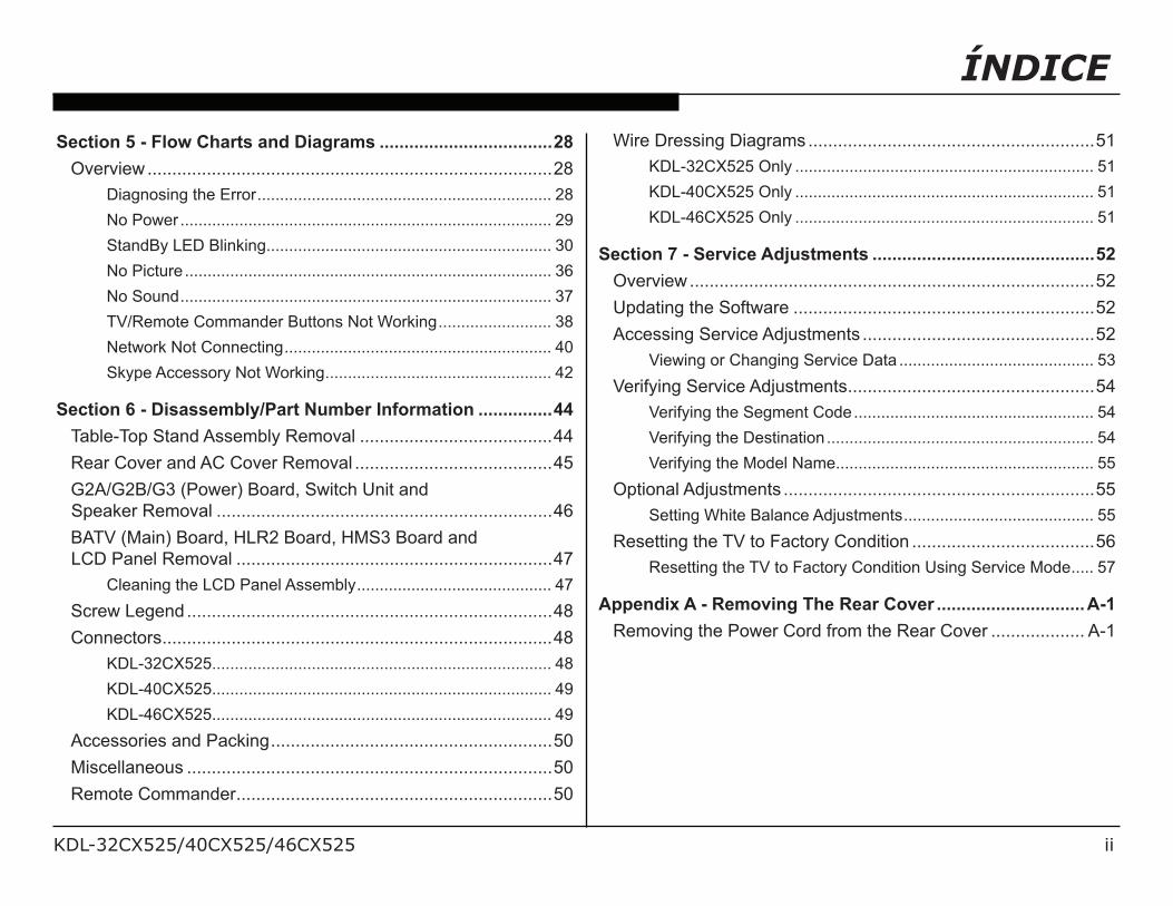
Section 5 - Flow Charts and Diagrams ...................................28
Overview ..................................................................................28
Diagnosing the Error ................................................................. 28
No Power .................................................................................. 29
StandBy LED Blinking ............................................................... 30
No Picture ................................................................................. 36
No Sound .................................................................................. 37
TV/Remote Commander Buttons Not Working ......................... 38
Network Not Connecting ........................................................... 40
Skype Accessory Not Working .................................................. 42
Section 6 - Disassembly/Part Number Information ...............44
Table-Top Stand Assembly Removal .......................................44
Rear Cover and AC Cover Removal ........................................45
G2A/G2B/G3 (Power) Board, Switch Unit and
Speaker Removal ....................................................................46
BATV (Main) Board, HLR2 Board, HMS3 Board and
LCD Panel Removal ................................................................47
Cleaning the LCD Panel Assembly ........................................... 47
Screw Legend ..........................................................................48
Connectors ...............................................................................48
KDL-32CX525 ........................................................................... 48
KDL-40CX525 ........................................................................... 49
KDL-46CX525 ........................................................................... 49
Accessories and Packing .........................................................50
Miscellaneous ..........................................................................50
Remote Commander ................................................................50
Wire Dressing Diagrams ..........................................................51
KDL-32CX525 Only .................................................................. 51
KDL-40CX525 Only .................................................................. 51
KDL-46CX525 Only .................................................................. 51
Section 7 - Service Adjustments .............................................52
Overview ..................................................................................52
Updating the Software .............................................................52
Accessing Service Adjustments ...............................................52
Viewing or Changing Service Data ........................................... 53
Verifying Service Adjustments ..................................................54
Verifying the Segment Code ..................................................... 54
Verifying the Destination ........................................................... 54
Verifying the Model Name ......................................................... 55
Optional Adjustments ...............................................................55
Setting White Balance Adjustments .......................................... 55
Resetting the TV to Factory Condition .....................................56
Resetting the TV to Factory Condition Using Service Mode ..... 57
Appendix A - Removing The Rear Cover ..............................A-1
Removing the Power Cord from the Rear Cover ................... A-1
KDL-32CX525/40CX525/46CX525 1
CUIDADOS E PRECAUÇÕES
CAUTION
34#+#/+#25%$%*6/%*+(2-$(%)*+/'2#/7)2/-+#/89/:-'1%&#./+#25%$#/"#2+)**#1/)*19;/3)/2#.-$#/(4#/2%+</)7/#1#$(2%$/+4)$<=/.)/*)(/"#27)20/'*9/+#25%$%*6/)(4#2/(4'*/(4'(/$)*('%*#./%*/(4#/)"#2'(%*6/%*+(2-$(%)*+/-*1#++/9)-/'2#/:-'1%&#./()/.)/+);
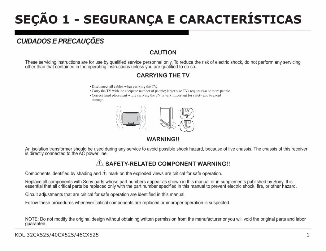
CARRYING THE TV
isconnect all cables when carrying the TV.
arry the TV with the adequate number of people; larger size TVs require two or more people.
orrect hand placement while carrying the TV is very important for safety and to avoid
damage.
WARNING!!
An isolation transformer should be used during any service to avoid possible shock hazard, because of live chassis. The chassis of this receiver is directly connected to the AC power line.
! SAFETY-RELATED COMPONENT WARNING!!
>)0")*#*(+/%.#*(%&#./89/+4'.%*6/'*./! mark on the exploded views are critical for safe operation.
Replace all components with Sony parts whose part numbers appear as shown in this manual or in supplements published by Sony. It is #++#*(%'1/(4'(/'11/$2%(%$'1/"'2(+/8#/2#"1'$#./)*19/?%(4/(4#/"'2(/*-08#2/+"#$%&#./%*/(4%+/0'*-'1/()/"2#5#*(/#1#$(2%$/+4)$<=/&2#=/)2/)(4#2/4'@'2.;
>%2$-%(/'.A-+(0#*(+/(4'(/'2#/$2%(%$'1/7)2/+'7#/)"#2'(%)*/'2#/%.#*(%&#./%*/(4%+/0'*-'1;/
Follow these procedures whenever critical components are replaced or improper operation is suspected.
NOTE: Do not modify the original design without obtaining written permission from the manufacturer or you will void the original parts and labor guarantee.
SEÇÃO 1 - SEGURANÇA E CARACTERÍSTICAS
KDL-32CX525/40CX525/46CX525 2
SEÇÃO 1 - SEGURANÇA E CARACTERÍSTICAS
ATENSÃO1. ! Do Not use paper towels, any type of abrasive pad, rags, rubber or vinyl materials to clean the screen. Using these materials
could easily scratch the screen which may result in permanent damage.
2. ! Do Not use any cleaning product containing alkaline/acid cleaner, scouring powder, or volatile solvent, such as alcohol, ammonia,
benzene, thinner or insecticide. Using any of these harsh cleaners may result in permanent damage to the screen.
3. ! Do Not spray water or detergent directly onto the TV screen . If liquid drips into the bottom of the screen it may cause a failure.
4.
LIMPANDO PAINEL DE LCD5. CAUTION: When cleaning the TV, be sure to unplug the power cord to avoid any chance of electric shock.
6. Clean the cabinet of the TV with a dry soft cloth.
7. Wipe the LCD screen gently with a soft cloth.
8. " Stubborn stains may be removed with a cloth slightly moistened with a solution of mild soap and warm water.
9. " If using a chemically pretreated cloth, please follow the instruction provided on the package.
10. " Never use strong solvents such as a thinner, alcohol or benzine for cleaning.
11. " Periodic vacuuming of the ventilation openings is recommended to ensure to proper ventilation.
KDL-32CX525/40CX525/46CX525 3
SEÇÃO 1 - SEGURANÇA E CARACTERÍSTICAS
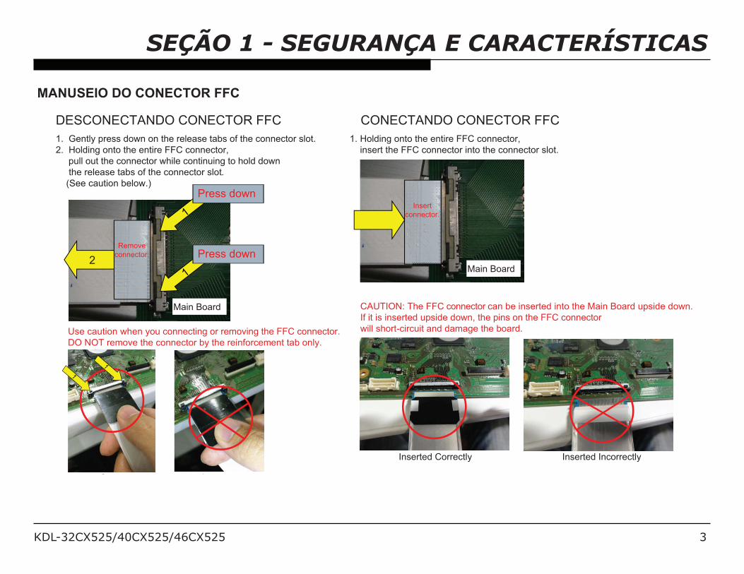
MANUSEIO DO CONECTOR FFC
Use caution when you connecting or removing the FFC connector.
DO NOT remove the connector by the reinforcement tab only.
1. Holding onto the entire FFC connector,
insert the FFC connector into the connector slot.
1. Gently press down on the release tabs of the connector slot.
2. Holding onto the entire FFC connector,
pull out the connector while continuing to hold down
the release tabs of the connector slot.
(See caution below.)
Insert
connector.
2
Press down
Press down
Main Board
Main Board
CAUTION: The FFC connector can be inserted into the Main Board upside down.
If it is inserted upside down, the pins on the FFC connector
will short-circuit and damage the board.
Remove
connector.
Inserted Correctly Inserted Incorrectly
Correct Incorrect
DESCONECTANDO CONECTOR FFC CONECTANDO CONECTOR FFC
KDL-32CX525/40CX525/46CX525 4
SEÇÃO 1 - SEGURANÇA E CARACTERÍSTICAS
CUIDADO COM A SEGURANÇA
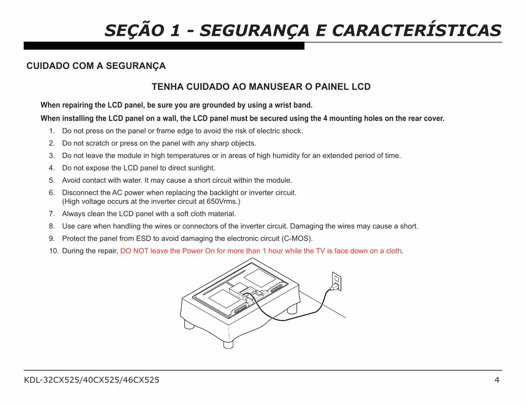
TENHA CUIDADO AO MANUSEAR O PAINEL LCD
When repairing the LCD panel, be sure you are grounded by using a wrist band.
When installing the LCD panel on a wall, the LCD panel must be secured using the 4 mounting holes on the rear cover.
1. Do not press on the panel or frame edge to avoid the risk of electric shock.
2. Do not scratch or press on the panel with any sharp objects.
3. Do not leave the module in high temperatures or in areas of high humidity for an extended period of time.
4. Do not expose the LCD panel to direct sunlight.
5. Avoid contact with water. It may cause a short circuit within the module.
6. Disconnect the AC power when replacing the backlight or inverter circuit.
(High voltage occurs at the inverter circuit at 650Vrms.)
7. Always clean the LCD panel with a soft cloth material.
8. Use care when handling the wires or connectors of the inverter circuit. Damaging the wires may cause a short.
9. Protect the panel from ESD to avoid damaging the electronic circuit (C-MOS).
10. During the repair, DO NOT leave the Power On for more than 1 hour while the TV is face down on a cloth.
KDL-32CX525/40CX525/46CX525 5
SEÇÃO 1 - SEGURANÇA E CARACTERÍSTICAS
VERIFICAÇÃO DE SEGURANÇA
After correcting the original service problem, perform the following safety checks before releasing the set to the customer:
1. Check the area of your repair for unsoldered or poorly soldered connections. Check the entire board surface for solder splashes and
bridges.
2. Check the interboard wiring to ensure that no wires are “pinched” or touching high-wattage resistors.
3. Check that all control knobs, shields, covers, ground straps, and mounting hardware have been replaced. Be absolutely certain that
you have replaced all the insulators.
4. Look for unauthorized replacement parts, particularly transistors, that were installed during a previous repair. Point them out to the
customer and recommend their replacement.
5. Look for parts which, though functioning, show obvious signs of deterioration. Point them out to the customer and recommend their
replacement.
6. Check the line cords for cracks and abrasion. Recommend the replacement of any such line cord to the customer.
7. Check the antenna terminals, metal trim, “metallized” knobs, screws, and all other exposed metal parts for AC leakage. Check leakage
as described below.
KDL-32CX525/40CX525/46CX525 6
SEÇÃO 1 - SEGURANÇA E CARACTERÍSTICAS
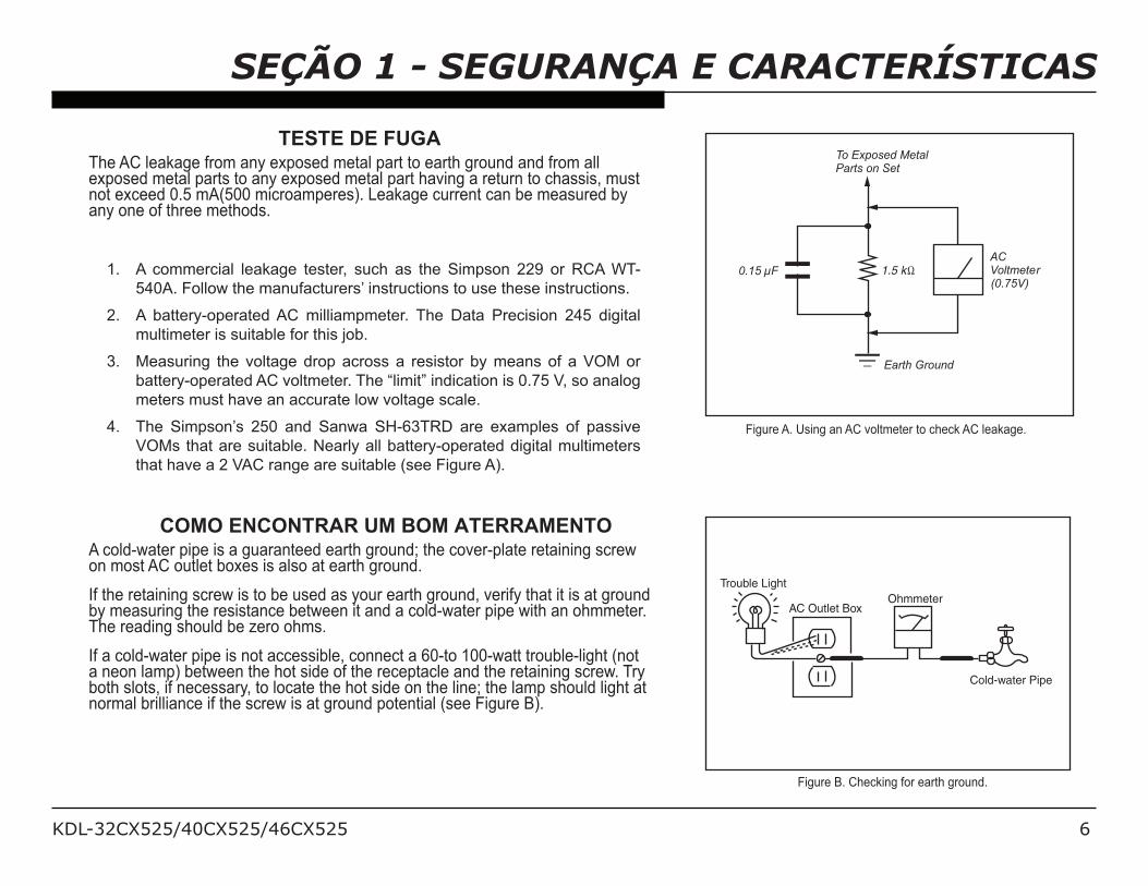
TESTE DE FUGAThe AC leakage from any exposed metal part to earth ground and from all exposed metal parts to any exposed metal part having a return to chassis, must not exceed 0.5 mA(500 microamperes). Leakage current can be measured by any one of three methods.
1. A commercial leakage tester, such as the Simpson 229 or RCA WT-
540A. Follow the manufacturers’ instructions to use these instructions.
2. A battery-operated AC milliampmeter. The Data Precision 245 digital
multimeter is suitable for this job.
3. Measuring the voltage drop across a resistor by means of a VOM or
battery-operated AC voltmeter. The “limit” indication is 0.75 V, so analog
meters must have an accurate low voltage scale.
4. The Simpson’s 250 and Sanwa SH-63TRD are examples of passive
VOMs that are suitable. Nearly all battery-operated digital multimeters
that have a 2 VAC range are suitable (see Figure A).
COMO ENCONTRAR UM BOM ATERRAMENTOA cold-water pipe is a guaranteed earth ground; the cover-plate retaining screw on most AC outlet boxes is also at earth ground.
If the retaining screw is to be used as your earth ground, verify that it is at ground by measuring the resistance between it and a cold-water pipe with an ohmmeter. The reading should be zero ohms.
If a cold-water pipe is not accessible, connect a 60-to 100-watt trouble-light (not a neon lamp) between the hot side of the receptacle and the retaining screw. Try both slots, if necessary, to locate the hot side on the line; the lamp should light at normal brilliance if the screw is at ground potential (see Figure B).
Trouble Light
AC Outlet BoxOhmmeter
Cold-water Pipe
Figure B. Checking for earth ground.
To Exposed MetalParts on Set
0.15 µF
Earth Ground
ACVoltmeter(0.75V)
Figure A. Using an AC voltmeter to check AC leakage.
KDL-32CX525/40CX525/46CX525 7
SEÇÃO 1 - SEGURANÇA E CARACTERÍSTICAS
FUNÇÃO DE AUTO-DIAGNÓSTICO
34#/3B+/%*/(4%+/0'*-'1/$)*('%*/'/+#17C.%'6*)+(%$/7-*$(%)*;/D7/'*/#22)2/)$$-2+=/(4#/!3,EFGH/IJF/?%11/'-()0'(%$'119/8#6%*/()/K'+4;/34#/*-08#2/)7/
(%0#+/(4#/IJF/K'+4#+/(2'*+1'(#+/()/'/"2)8'81#/+)-2$#/)7/(4#/"2)81#0;/,/.#&*%(%)*/)7/(4#/!3,EFGH/IJF/K'+4/%*.%$'()2/%+/1%+(#./%*/(4#/L"#2'(%*6/
Instruction manual for the user’s reference.
If an error symptom cannot be reproduced, the remote commander can be used to review the failure occurrence data stored in memory to reveal
past problems and how often these problems occur.
For complete information, refer to “Section 4 - Troubleshooting” on page 22.
Self DiagnosisSupported model
KDL-32CX525/40CX525/46CX525 8
SEÇÃO 1 - SEGURANÇA E CARACTERÍSTICAS
VISÃO GERAL
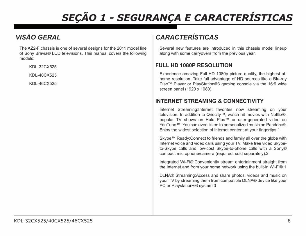
The AZ2-F chassis is one of several designs for the 2011 model line
of Sony Bravia® LCD televisions. This manual covers the following
models:
KDL-32CX525
KDL-40CX525
KDL-46CX525
CARACTERÍSTICAS
Several new features are introduced in this chassis model lineup
along with some carryovers from the previous year.
FULL HD 1080P RESOLUTION
Experience amazing Full HD 1080p picture quality, the highest at-
home resolution. Take full advantage of HD sources like a Blu-ray
Disc™ Player or PlayStation®3 gaming console via the 16:9 wide
screen panel (1920 x 1080).
INTERNET STREAMING & CONNECTIVITY
Internet Streaming:Internet favorites now streaming on your
(#1#5%+%)*;/D*/'..%(%)*/()/M2%)$%(9N=/?'($4/4%(/0)5%#+/?%(4/E#(K%OP=/
popular TV shows on Hulu Plus™ or user-generated video on
YouTube™. You can even listen to personalized music on Pandora®.
J*A)9/(4#/?%.#+(/+#1#$(%)*/)7/%*(#2*#(/$)*(#*(/'(/9)-2/&*6#2(%"+;Q
Skype™ Ready:Connect to friends and family all over the globe with
Internet voice and video calls using your TV. Make free video Skype-
to-Skype calls and low-cost Skype-to-phone calls with a Sony®
compact microphone/camera (required, sold separately).2
Integrated Wi-Fi®:Conveniently stream entertainment straight from
the Internet and from your home network using the built-in Wi-Fi®.1
DLNA® Streaming:Access and share photos, videos and music on
your TV by streaming them from compatible DLNA® device like your
PC or Playstation®3 system.3
KDL-32CX525/40CX525/46CX525 9
SEÇÃO 1 - SEGURANÇA E CARACTERÍSTICAS
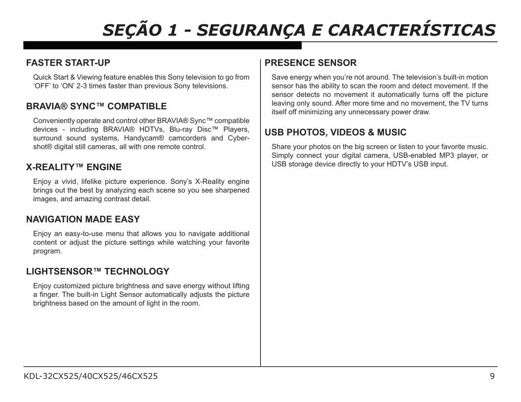
FASTER START-UP
Quick Start & Viewing feature enables this Sony television to go from
‘OFF’ to ‘ON’ 2-3 times faster than previous Sony televisions.
BRAVIA® SYNC™ COMPATIBLE
Conveniently operate and control other BRAVIA® Sync™ compatible
devices - including BRAVIA® HDTVs, Blu-ray Disc™ Players,
surround sound systems, Handycam® camcorders and Cyber-
shot® digital still cameras, all with one remote control.
X-REALITY™ ENGINE
Enjoy a vivid, lifelike picture experience. Sony’s X-Reality engine
brings out the best by analyzing each scene so you see sharpened
images, and amazing contrast detail.
NAVIGATION MADE EASY
Enjoy an easy-to-use menu that allows you to navigate additional
content or adjust the picture settings while watching your favorite
program.
LIGHTSENSOR™ TECHNOLOGY
Enjoy customized picture brightness and save energy without lifting
'/&*6#2;/34#/8-%1(C%*/I%64(/!#*+)2/'-()0'(%$'119/'.A-+(+/(4#/"%$(-2#/
brightness based on the amount of light in the room.
PRESENCE SENSOR
Save energy when you’re not around. The television’s built-in motion
sensor has the ability to scan the room and detect movement. If the
sensor detects no movement it automatically turns off the picture
leaving only sound. After more time and no movement, the TV turns
itself off minimizing any unnecessary power draw.
USB PHOTOS, VIDEOS & MUSIC
Share your photos on the big screen or listen to your favorite music.
Simply connect your digital camera, USB-enabled MP3 player, or
USB storage device directly to your HDTV’s USB input.

KDL-32CX525/40CX525/46CX525 10
SEÇÃO 1 - SEGURANÇA E CARACTERÍSTICAS
ESPECIFICAÇÕESSistema
Sistema de televisão Analógico: NTSC/PAL-M/PAL-NDigital: SBTVD-T
Cobertura de canais VHF: 2-13UHF: 14-69CATV: 1-125
Sistema do painel Painel LCD (tela de cristal líquido)Potência de saída dos alto-falantes (RMS)
10 W + 10 W (8 ohms, 1 kHz, 10% THD*1, 127 V)
Tomadas de entrada/saída
CABLE/ANTENNA Terminal de antena externa de 75 ohms para entradas RFVIDEO IN 1/2 VIDEO / AUDIOCOMPONENT IN YPBPR (Vídeo componente) / Formato de sinal: 480i, 480p, 576i, 576p, 720p, 1080i, 1080p / AUDIOHDMI IN 1/2/3/4 HDMI: Vídeo: 480i, 480p, 576i, 576p, 720p, 720/24p/30p, 1080i, 1080p, 1080/24p/30p
Áudio: Linear de dois canais PCM 32, 44,1 e 48 kHz, 16, 20 e 24 bits, Dolby DigitalEntrada de áudio analógico (minitomada) (somente HDMI IN 4)ARC (Audio Return Channel, Canal de Retorno de Áudio) (somente HDMI IN 1)
AUDIO OUT/Fones de ouvido 500 mVrms (típico)Minitomada estéreo / Impedância: ≥ 16 ohms
DIGITAL AUDIO OUT (OPTICAL)
Sinal óptico PCM/Dolby Digital
ocigólana BGR ,sonip 51 ed bus-DNI CPPC/HDMI 4 AUDIO IN Minitomada estéreo
PC/HDMI 2 AUDIO IN Minitomada estéreo
ad edadicolev A( XT-ESAB001/T-ESAB01 rotcenoCNAL conexão pode ser diferente dependendo do ambiente
de rede. A taxa e a qualidade de comunicação de 10BASE-T/100BASE-TX não estão garantidas nesta
TV.)*2
.odatropus otamrof o erbos seõçamrofni retbo arap launaM-i o etlusnoCANLD/BSU
*1 Distorção Harmônica Total.
*2 Para conexões LAN, utilize um cabo 10BASE-T/100BASE-TX de categoria 7 (não fornecido).
A disponibilidade dos acessórios opcionais depende do estoque.
A disponibilidade dos acessórios opcionais depende do país/região.
Projeto e especificações técnicas sujeitos a alterações sem prévio aviso.
Os pesos e dimensões são aproximados.
KDL-32CX525/40CX525/46CX525 11
SEÇÃO 1 - SEGURANÇA E CARACTERÍSTICAS
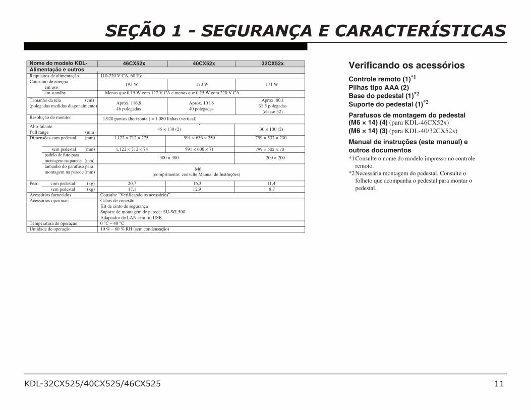
Nome do modelo KDL- 46CX52x 40CX52x 32CX52xAlimentação e outrosRequisitos de alimentação 110-220 V CA, 60 Hz
Consumo de energia193 W
em uso
em standby Menos que 0,15 W com 127 V CA e menos que 0,25 W com 220 V CA
Tamanho da tela (cm)
(polegadas medidas diagonalmente)Aprox. 101,6
40 polegadas
Aprox. 116,8
46 polegadas
Aprox. 80,1
31,5 polegadas
(classe 32)
Resolução do monitor 1.920 pontos (horizontal) × 1.080 linhas (vertical)
Alto-falante
Full range (mm))2( 001 × 03)2( 031 × 54
Dimensões com pedestal (mm) 1,122 × 712 × 275 991 × 636 × 250
sem pedestal (mm) 1,122 × 712 × 74 991 × 606 × 71
799 × 532 × 230
799 × 502 × 70
padrão de furo para
montagem na parede (mm)002 × 002003 × 003
tamanho do parafuso para
montagem na parede (mm)6M
(comprimento: consulte Manual de Instruções)
Peso com pedestal (kg) 20,7 16,3 11,4
sem pedestal (kg) 17,1 12,9 8,7
Acessórios fornecidos Consulte “Verificando os acessórios”.
Acessórios opcionais Cabos de conexão
Kit de cinto de segurança
Suporte de montagem de parede: SU-WL500
Adaptador de LAN sem fio USB
Temperatura de operação 0 °C – 40 °C
Umidade de operação 10 % – 80 % RH (sem condensação)
170 W 171 W
Verificando os acessórios
Controle remoto (1)*1
Pilhas tipo AAA (2)
Base do pedestal (1)*2
Suporte do pedestal (1)*2
(M6 × 14) (4) (para KDL-46CX52x)
(M6 × 14) (3) (para KDL-40/32CX52x)
Manual de instruções (este manual) e
outros documentos*1Consulte o nome do modelo impresso no controle
remoto.
*2Necessária montagem do pedestal. Consulte o
folheto que acompanha o pedestal para montar o
pedestal.
Parafusos de montagem do pedestal
KDL-32CX525/40CX525/46CX525 12
SEÇÃO 1 - SEGURANÇA E CARACTERÍSTICAS
Informações sobre marcas registradas
Macintosh é uma marca comercial
licenciada da Apple Inc., registrada nos E.U.A. e em outros países.
Blu-ray Disc é uma marca comercial.
“BRAVIA” e , S-Force,
Motionflow, BRAVIA Sync e são marcas comerciais ou marcas registradas
da Sony Corporation.
“PS3” é uma marca comercial da Sony
Corporation e/ou Sony Computer Entertainment Inc.
HDMI, o logotipo HDMI e High-Definition Multimedia Interface são marcas
comerciais ou marcas registradas da HDMI Licensing LLC nos Estados
Unidos e em outros países.
Java e todas as marcas e logotipos
baseados em Java são marcas comerciais ou marcas registradas da Oracle e/ou de
suas empresas filiadas. Outros nomes podem ser marcas comerciais de seus
respectivos proprietários.
Astro TV é um software desenvolvido
pela TQTVD Software Ltda. que implementa a norma de interatividade do
Sistema Brasileiro de TV Digital “Ginga” NBR-15606.
GINGA® é uma marca registrada da PUC-Rio/UFPB.
NCL® é uma marca registrada da
PUC-Rio.
Fabricada sob licença da Dolby
Laboratories. Dolby e o símbolo de dois D são marcas comerciais da Dolby
Laboratories.
DLNA®, o logotipo DLNA e DLNA
CERTIFIED® são marcas comerciais, marcas de serviço ou marcas de
certificação da Digital Living Network Alliance.
TrackID é uma marca comercial ou marcas registrada da Sony Ericsson
Mobile Communications AB.
A tecnologia de reconhecimento de
música e vídeo e os dados relacionados são fornecidos pela Gracenote®. Gracenote é o padrão de indústria em tecnologia de reconhecimento de música
e fornecimento de conteúdos relacionados. Para mais informações,
visite www.gracenote.com. CD, DVD, Blu-ray Disc e dados
relacionados com música e vídeo da Gracenote, Inc., copyright © 2000-
present Gracenote. Gracenote Software, copyright © 2000-present Gracenote.
Uma ou mais patentes propriedades da Gracenote aplicam-se a este produto e
serviço. Visite a página da web da Gracenote para ver uma lista não
exaustiva de patentes Gracenote aplicáveis. Gracenote, CDDB, MusicID,
MediaVOCS, os logotipos Gracenote e o logotipo "Powered by Gracenote" são
marcas registradas ou marcas comerciais da Gracenote nos Estados Unidos e/ou
em outros países.
Navegador Opera® da Opera Software ASA. Copyright 1995-2010 Opera
Software ASA. Todos os direitos reservados.
KDL-32CX525/40CX525/46CX525 13
VISÃO GERAL
There are 2 reasons for updating the software on the TVs.
! Software updates for customers
These updates are for enhancements or improvements that
have been made to the software after the TV was released.
! Software update for servicers
/ 34#+#/-".'(#+/'2#/+"#$%&$'119/7)2/+#25%$#2+/()/-+#/.-2%*6/'/
service call.
ATUALIZAÇÃO DE SOFTWARE PARA CONSUMIDOR
The subject of software updates is a very important. The televisions
of today have advanced to the point where they are not simply a
television anymore. They are evolving into devices that are designed
to integrate with numerous other devices found in the home. Some
examples are: Portable audio and video devices, still cameras, home
computer networks and accessing the internet to name a few.
Communications with these varying devices requires that the
television be compatible with varying communications protocols.
Although standards are detailed for each of these protocols, the real
world dictates that occasional errors may occur that could prevent
devices from operating or communicating properly.
Keeping the software in the television up-to-date is a procedure that
is normally handled by the owner of the television. Most customers
who own computers and other digital devices are familiar with and are
accustomed to updating the software in their products. If a customer
contacts the Sony Customer Support Center and it is deemed to
be correctable with a software update, the issue is handled at the
customer level.
SEÇÃO 2 - REQUISITOS DE SOFTWARE
KDL-32CX525/40CX525/46CX525 14
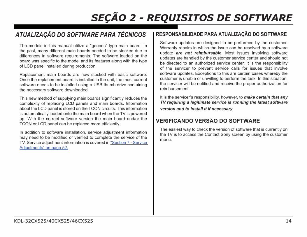
SEÇÃO 2 - REQUISITOS DE SOFTWAREATUALIZAÇÃO DO SOFTWARE PARA TÉCNICOS
The models in this manual utilize a “generic” type main board. In
the past, many different main boards needed to be stocked due to
differences in software requirements. The software loaded on the
8)'2./?'+/+"#$%&$/()/(4#/0).#1/'*./%(+/7#'(-2#+/'1)*6/?%(4/(4#/(9"#/
of LCD panel installed during production.
Replacement main boards are now stocked with basic software.
Once the replacement board is installed in the unit, the most current
software needs to be installed using a USB thumb drive containing
the necessary software downloaded.
34%+/*#?/0#(4)./)7/+-""19%*6/0'%*/8)'2.+/+%6*%&$'*(19/2#.-$#+/(4#/
complexity of replacing LCD panels and main boards. Information
about the LCD panel is stored on the TCON circuits. This information
is automatically loaded onto the main board when the TV is powered
up. With the correct software version the main board and/or the
3>LE/)2/I>F/"'*#1/$'*/8#/2#"1'$#./0)2#/#7&$%#*(19;
In addition to software installation, service adjustment information
0'9/*##./()/8#/0).%&#./)2/5#2%&#./()/$)0"1#(#/(4#/+#25%$#/)7/(4#/
TV. Service adjustment information is covered in “Section 7 - Service
Adjustments” on page 52.
RESPONSABILIDADE PARA ATUALIZAÇÃO DO SOFTWARESoftware updates are designed to be performed by the customer.
Warranty repairs in which the issue can be resolved by a software
update are not reimbursable. Most issues involving software
updates are handled by the customer service center and should not
be directed to an authorized service center. It is the responsibility
of the servicer to prevent service calls for issues that involve
software updates. Exceptions to this are certain cases whereby the
customer is unable or unwilling to perform the task. In this situation,
(4#/+#25%$#2/?%11/8#/*)(%&#./'*./2#$#%5#/(4#/"2)"#2/'-(4)2%@'(%)*/7)2/
reimbursement.
It is the servicer’s responsibility, however, to make certain that any
TV requiring a legitimate service is running the latest software
version and to install it if necessary.
VERIFICANDO VERSÃO DO SOFTWAREThe easiest way to check the version of software that is currently on
the TV is to access the Contact Sony screen by using the customer
menu.
KDL-32CX525/40CX525/46CX525 15
SEÇÃO 2 - REQUISITOS DE SOFTWAREEXEMPLO DE SINTOMAS CORRIGÍVEIS DOSOFTWARE
Most symptoms that are correctable by software updates involve
communications issues with other devices or minor glitches in
(4#/)"#2'(%)*/)7/'/+"#$%&$/ 7-*$(%)*;/G#1)?/ %+/'/ 1%+(/)7/+)0#/)7/ (4#/
symptoms that may be corrected with a software update:
! Fluctuations in picture brightness
! Intermittent picture freezing or noise
! Problems with certain inputs (especially HDMI)
! Intermittent or distorted audio
! Erratic remote control operation
! Unit turns on and off by itself
! Loss of color
! Internet connectivity
! Certain features not working correctly
R"4)()/)2/5%.#)/&1#/5%#?%*6SI)++/)7/$)1)2
! Internet connectivity
! Certain features not working correctly
R"4)()/)2/5%.#)/&1#/5%#?%*6S
KDL-32CX525/40CX525/46CX525 16
SEÇÃO 3 - VISÃO GERAL DO CHASSIS
VISÃO GERAL
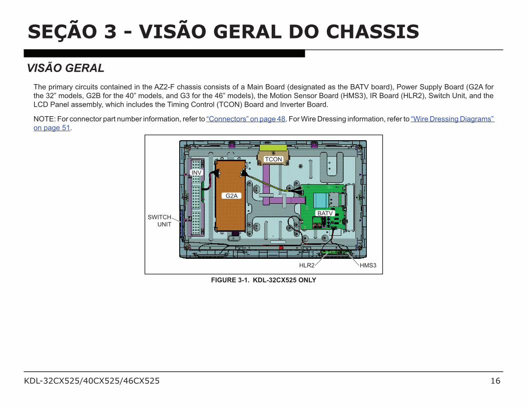
The primary circuits contained in the AZ2-F chassis consists of a Main Board (designated as the BATV board), Power Supply Board (G2A for
the 32” models, G2B for the 40” models, and G3 for the 46” models), the Motion Sensor Board (HMS3), IR Board (HLR2), Switch Unit, and the
LCD Panel assembly, which includes the Timing Control (TCON) Board and Inverter Board.
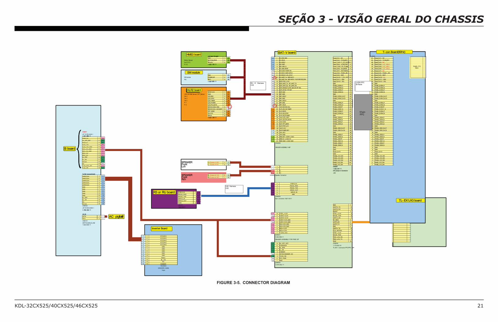
NOTE: For connector part number information, refer to “Connectors” on page 48. For Wire Dressing information, refer to “Wire Dressing Diagrams”
on page 51.
SWITCH
UNIT
HLR2 HMS3
G2A
TCON
BATV
INV
FIGURE 3-1. KDL-32CX525 ONLY
KDL-32CX525/40CX525/46CX525 17
SEÇÃO 3 - VISÃO GERAL DO CHASSIS
SWITCH
UNIT
HLR2 HMS3
G2B
INV
BATV
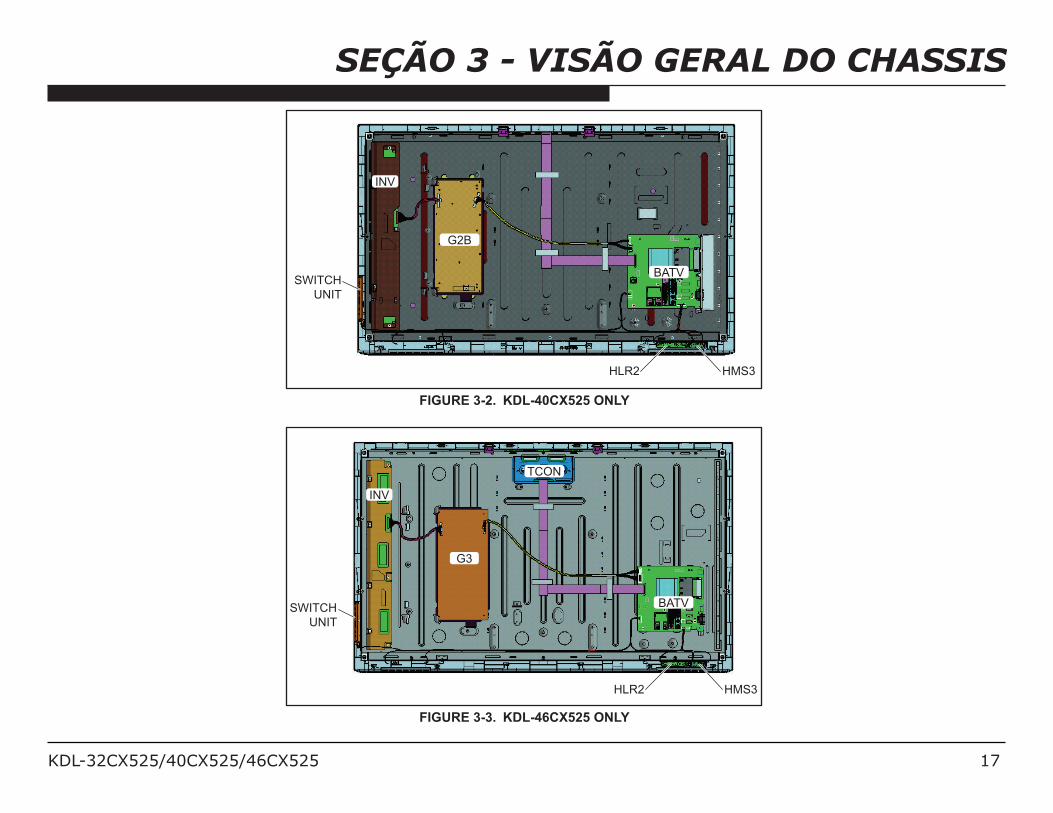
FIGURE 3-2. KDL-40CX525 ONLY
SWITCH
UNIT
HLR2 HMS3
G3
BATV
TCON
INV
FIGURE 3-3. KDL-46CX525 ONLY
KDL-32CX525/40CX525/46CX525 18
SEÇÃO 3 - VISÃO GERAL DO CHASSIS
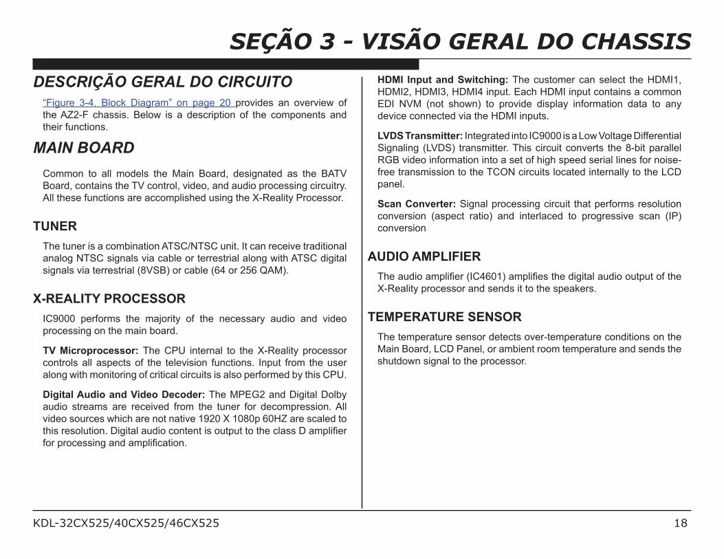
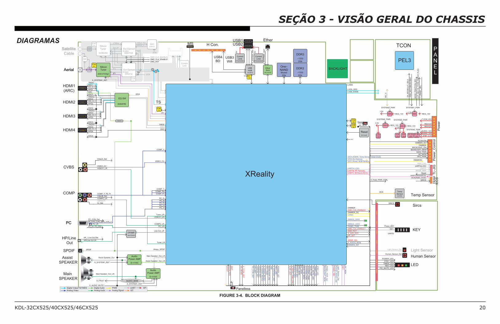
DESCRIÇÃO GERAL DO CIRCUITO“Figure 3-4. Block Diagram” on page 20 provides an overview of
the AZ2-F chassis. Below is a description of the components and
their functions.
MAIN BOARD
Common to all models the Main Board, designated as the BATV
Board, contains the TV control, video, and audio processing circuitry.
All these functions are accomplished using the X-Reality Processor.
TUNER
The tuner is a combination ATSC/NTSC unit. It can receive traditional
analog NTSC signals via cable or terrestrial along with ATSC digital
signals via terrestrial (8VSB) or cable (64 or 256 QAM).
X-REALITY PROCESSOR
IC9000 performs the majority of the necessary audio and video
processing on the main board.
TV Microprocessor: The CPU internal to the X-Reality processor
controls all aspects of the television functions. Input from the user
along with monitoring of critical circuits is also performed by this CPU.
Digital Audio and Video Decoder: The MPEG2 and Digital Dolby
audio streams are received from the tuner for decompression. All
video sources which are not native 1920 X 1080p 60HZ are scaled to
(4%+/2#+)1-(%)*;/F%6%('1/'-.%)/$)*(#*(/%+/)-("-(/()/(4#/$1'++/F/'0"1%/
7)2/"2)$#++%*6/'*./'0"1%&$'(%)*;
HDMI Input and Switching: The customer can select the HDMI1,
HDMI2, HDMI3, HDMI4 input. Each HDMI input contains a common
EDI NVM (not shown) to provide display information data to any
device connected via the HDMI inputs.
LVDS Transmitter: Integrated into IC9000 is a Low Voltage Differential
Signaling (LVDS) transmitter. This circuit converts the 8-bit parallel
RGB video information into a set of high speed serial lines for noise-
free transmission to the TCON circuits located internally to the LCD
panel.
Scan Converter: Signal processing circuit that performs resolution
conversion (aspect ratio) and interlaced to progressive scan (IP)
conversion
AUDIO AMPLIFIER
34#/'-.%)/'0"1%/RD>TUVQS/'0"1%&#+/(4#/.%6%('1/'-.%)/)-("-(/)7/(4#/
X-Reality processor and sends it to the speakers.
TEMPERATURE SENSOR
The temperature sensor detects over-temperature conditions on the
Main Board, LCD Panel, or ambient room temperature and sends the
shutdown signal to the processor.
KDL-32CX525/40CX525/46CX525 19
SEÇÃO 3 - VISÃO GERAL DO CHASSIS
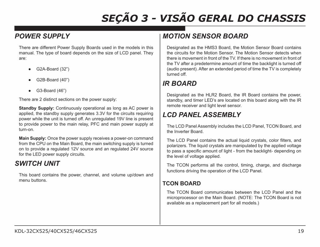
POWER SUPPLY
There are different Power Supply Boards used in the models in this
manual. The type of board depends on the size of LCD panel. They
are:
! G2A-Board (32”)
! G2B-Board (40”)
! G3-Board (46”)
There are 2 distinct sections on the power supply:
Standby Supply: Continuously operational as long as AC power is
applied, the standby supply generates 3.3V for the circuits requiring
power while the unit is turned off. An unregulated 19V line is present
to provide power to the main relay, PFC and main power supply at
turn-on.
Main Supply: Once the power supply receives a power-on command
from the CPU on the Main Board, the main switching supply is turned
on to provide a regulated 12V source and an regulated 24V source
for the LED power supply circuits.
SWITCH UNIT
This board contains the power, channel, and volume up/down and
menu buttons.
MOTION SENSOR BOARD
Designated as the HMS3 Board, the Motion Sensor Board contains
the circuits for the Motion Sensor. The Motion Sensor detects when
there is movement in front of the TV. If there is no movement in front of
the TV after a predetermine amount of time the backlight is turned off
(audio present). After an extended period of time the TV is completely
turned off.
IR BOARD
Designated as the HLR2 Board, the IR Board contains the power,
standby, and timer LED’s are located on this board along with the IR
remote receiver and light level sensor.
LCD PANEL ASSEMBLY
The LCD Panel Assembly includes the LCD Panel, TCON Board, and
the Inverter Board.
34#/I>F/W'*#1/$)*('%*+/(4#/'$(-'1/ 1%:-%./$29+('1+=/$)1)2/&1(#2+=/'*./
polarizers. The liquid crystals are manipulated by the applied voltage
()/"'++/'/+"#$%&$/'0)-*(/)7/1%64(/C/72)0/(4#/8'$<1%64(C/.#"#*.%*6/)*/
the level of voltage applied.
The TCON performs all the control, timing, charge, and discharge
functions driving the operation of the LCD Panel.
TCON BOARD
The TCON Board communicates between the LCD Panel and the
microprocessor on the Main Board. (NOTE: The TCON Board is not
available as a replacement part for all models.)
KDL-32CX525/40CX525/46CX525 20
SEÇÃO 3 - VISÃO GERAL DO CHASSIS
48M
32.768K
[PST3629]
GND
Push
PANEL
[LM75B]
DDR3
–1333
2Gb
DDR3
–1333
2Gb
One–NANDMuxed
2Gb
[RTL8201E]
[TPS2553DBV]
[GL850G]
12M
[TPS2553DBV]
H/L
[D–510D]
[D–510D]
[NJU72040V]
41M
[LNBH23]
[MIC2005]
[SEKITO2]
[GAIA1a]
41M
[HORUS3]
27M
4M
[ASCOT2Sip]
[Sil9287B]
0
0
XReality
HDMI1
(ARC)
HDMI2
HDMI3
Aerial
Cable
Satellite
PCPC
COMP
CVBS
SPDIF
Main
SPEAKER
HP/Line
Out
Assist
SPEAKER
Analog Video
Digital Video/TS/TMDS
Analog Audio Analog Signal
PWM
I2C
SPI
X_SYSTEM1_RST
AUDIO_MONX_FAULT
Main Speaker_Out_LR
X_SYSTEM1_RST
Assist Speaker_Out
SPDIF
HP/Line Out LR
HP_/ Line Out Det
PC_5V, PC_DDC
PC_LR
PC_R,PC_G,PC_B,PC_H,PC_V
PC_CON_Det
Cr_Det
ASPECT1
COMP_Y, Pb, Pr
VideoB_Det
COMP2_LR
VideoA_Det
VIDEO_CV
VIDEO1_LR
CEC3
DDC4
HPD4
CEC4
DDC_5V_4
TMDS4
CEC2
DDC3
HPD3
DDC_5V_3
TMDS3
CEC1
TMDS2
DDC2
HPD2
DDC_5V_2
ARC
TMDS1
DDC1
HPD1
DDC_5V_1
EQ SW
3.3->1
I2CA
X_SYSTEM1_RST
TCON
Reset
Ether
PHY
X’tal
Temp
Sensor
Audio
Power AMP
HDMI4
Ether
KEY
LED
TMDS
DDC
CEC
Line Out_LR
Pow
er_
Contr
ol
MAIN_PWR
Power_KEY
KEY
Light_Sensor_Det
STBY_LED
POWER_LED
TL
-JIGUARTA(LOG)
Ho
telUARTC(Hotel/ECS)
BACKLIGHT_ON
DIMMER
BACKLIGHT_MON
SYSTEM2_PWR
Human SensorHuman_Sensor_Det
X_AUDIO_MUTE1
PFC_PWR
OPAMP
AC_MON
I2CA
X’tal
DIMMER_DC
USB2
Current
Limit
USB1
USB
HUB
X’tal
Pow
er
Tuner_LR
Current
LimitUSB3
Wifi
USB4
BD
AC
_M
ON
PF
C_M
ON
PO
WE
R_K
EY
PO
WE
R_
LE
D
RE
C_
LE
D
X_
SY
ST
EM
1_
RS
T
DIMMER
DC
_M
ON
KE
Y
Lig
ht_
Sensor_
Det
UARTA (LOG)
PF
C_P
WR
DE
BU
G_LE
D1
Hu
ma
n_
Se
nso
r_D
et
LVDS
PEL3
UARTDP
AN
EL
_S
EL
5V
Aerial
Ext Demod
X’tal
LNA Ext Demod
IFAGC
DDC
I2CB
I2CB
SatelliteSilicon
Tuner
X’tal
Silicon
Tuner
Zero-IF
IF1
X’tal
DiSEqC_Out
IFAGC
IF2
DiSEqC_In27MHz
SW
COMP_Y
COMP_Pb
COMP_Pr
PC_G
PC_B
PC_R
PC_H
PC_V
PC_LR
VIDEO1_LR
COMP2_LR
Tuner_LR
VIDEO_CV
COMP_Y
S1.8V
LDO
3.3V
LDO
DDC5V
STBY 3.3V2.5V
LDO
TCON-ON
SYSTEM2_PWR
DDCREG_12V
T-CON_VCC
REG12V
AUDIO_12V
REG_12V
BA
CK
LIG
HT
_M
ON
X_A
UD
IO_M
UT
E1
X_A
UD
IO_M
UT
E2
PA
NE
L_P
WR
_D
et
5V
UARTE
PC
_C
ON
_D
ET
Crystal
VID
EO
A_D
ET
VID
EO
B_D
ET
CR
_D
ET
TIMER_LED
PIC_MUTE_LED
REC_LED
Temp Sensor
X_Hotel_PWR_CTRL
Current
Limit
5V
I2CA (EQSW, Temp Sensor, Hotel Clock)
I2CB (Ext Demod)
LOGO
DMD_RST
X_AUDIO_MON
ST
BY
_LE
D
TIM
ER
_LE
D
MA
IN_P
WR
MA
IN_S
S_M
ON
DIMMER_DC
TS2
TS1
LNA
/EC
S
Light Sensor
X_T
CO
N_R
ST
SA
_M
OD
E
BIN
T
TC
ON
_R
DY
IF1
Main Speaker_Out_LR
S1.2V
LDO
PEM_LOG
I2CA(Hotel_Clock)
DEBUG_LED2
DEBUG_LED3
DMD_CLK_ENABLE1
PANEL_PWR
Atreyu_SPDIF
BA
CK
LIG
HT
_O
N
SY
ST
EM
2_
PW
R
SY
ST
EM
1_
PW
R
PIC
_M
UT
E_LE
D
1.5V
3.3V
MODE_PEM
I2CC (Panel, RGB Sensor)
DMD_CLK_ENABLE2
HDMIEQ_INT
DMD_RST
DMD_CLK_ENABLE1
DMD_CLK_ENABLE2
X_S
YS
TE
M1_R
ST
X_S
YS
TE
M1_R
ST
Reset
SIRCS
UARTB (RF-Remote)
UARTC (IR Blaster/ECS)
MS
TS
Panelless
AC_MON
Reset
H Con.
Audio
Power AMPAssist Speaker_Out_LR
SircsSIRCS
AUDIO_12V
REG12V
SYSTEM2_PWR
DDC1.2V
SYSTEM1_PWR
DDCREG_12V
3.4V
LDO
SYSTEM2_PWR
X_R
F_R
ST
NM
I
X_H
OT
EL_P
WR
_C
TR
L
DA
TA
1
HP_DET
X_WIFI_RST
SPDIF_SEL
BACKLIGHT
DIMMER2
LVDS_ODD
LVDS_EVEN
SA
_M
OD
E/L
UT
_S
EL0
PE
M_
WD
T/X
BU
SY
/BIN
T
I2C
_C
MO
DE
_P
EM
/TC
ON
_R
DY
LU
T_S
EL1/X
_T
CO
N_R
ST
/LR
_F
LA
G
T_P
AN
EL_S
EL
Digital Audio UART
REG_12V
FIGURE 3-4. BLOCK DIAGRAM
DIAGRAMAS
KDL-32CX525/40CX525/46CX525 21
SEÇÃO 3 - VISÃO GERAL DO CHASSIS
CN6401
JST B15B-XASK-1
1- 821- 889- 11
STBY3.3V 1 10
AC_OFF_DET 2 9
Power on 3 8
Audio_12V 4 8
Audio_12V_GND 5 7
REG_12V_GND 6 5
REG_12V_GND 7 4
REG_12V 8 3
REG_12V 9 2
BL_ERR 10 7
BL_ON 11 6
Dimmer 12 5
NC 13 NC
T-con_VCC_12V 14 1
T-con_ON 15 3
To INV (conventional)
UNREG24V 1 1
UNREG24V 2 2
UNREG24V 3 3
UNREG24V 4 4
UNREG24V 5 5
GND 6 6
GND 7 7
GND 8 8
GND 9 9
GND 10 10
BL_ERR 11 11
BL_ON 12 12
NC 13 13
Dimmer 14 14
CN6402
JST B14B-XASK-1
1- 793- 236- 11
AC_IN
AC-N 1 1
AC-L 2 2
CN6101
SFP79-02WLB JAM
1-822-908-11
STBY3.3V 1 1
RS232_RXD 2 2
RS232_TXD 3 3
SIRCS_IN 4 4
SIRCS_OUT 5 5
GND 6 6
CN101
182018311
B board
AC pig
R3 or RU board
B board
AC pig
1 1 VCC(24V)
2 2 VCC(24V)
3 3 VCC(24V)
4 4 VCC(24V)
5 5 VCC(24V)
DNG66
DNG77
DNG88
DNG99
10 10 GND
11 11 Status
12 12 BL_ON
CN3131
14 14 DIMMER
YEONHO
20022WR-14AML
14pin
Inverter Board
tailtail
Inverter Board
G-B HarnessG-B
JAM 3pin Straight To BAT
DNG BSU DB16041DNG CN / 1lrtC_lenaP151CN / 1lrtC_lenaP
SUBV DB21832SNES_NOITOMrosneS noitoM YDR_NOCT / 2lrtC_lenaP052YDR_NOCT / 2lrtC_lenaP
P_BSU DB33933V5+GER2/V/X-a3 Panel_Ctrl3 / T_TD_HSYNC / 3lrtC_lenaP943 NC
P-1/2 1- 821- 130- 11 4 4 BD GND / 4lrtC_lenaP844TSR_CRF_X / 4lrtC_lenaP LUT_SEL2
2 5 BD USB_N Panel_Ctrl5 / LR_FLAG(For / 5lrtC_lenaP745 LUT_SEL1
/ 6lrtC_lenaP646EDOM_AS / 6lrtC_lenaPFIDPS BSU DB65 LUT_SEL0
N(2NOTES / 7lrtC_lenaPNO RDB/TCEJE DB7CN C / 7lrtC_lenaP547 NC
AP / 8lrtC_lenaP448LES_LENAP / 8lrtC_lenaP1OIPG RDB/1CSID DB8CN NEL_SEL
B / 9lrtC_lenaP349TNIB / 9lrtC_lenaPTATS_LD_U/2CSID DB9CN731DNG INT
T_T / 01lrtC_lenaP1YEK RDB /xT TRAU DB01CN532TNI_REWOPeludom WS D_VSYN / 01lrtC_lenaP2401 NC
11lrtC_lenaPADS_ECIVED RLH/ 2YEK RDB /xR TRAU DB11CN6331YEKLLA ADS / 11lrtC_lenaP1411ADS /
1- 822- 693- 11 LCS / 21lrtC_lenaP0421LCS / 21lrtC_lenaPV3.3+_YBTS RDB21CN
DNG9331DNGXT_TRAU FR /xT_TRAU RDB31CN
P_4NEVE_LENAP8341P_4NEVE_LENAPXR_TRAU_FR /xR_TRAU RDB41CN
N_4NEVE_LENAP7351N_4NEVE_LENAPLES FR/NOCIM_YBTS_PUEKAW RDB51CN
P_3NEVE_LENAP6361P_3NEVE_LENAPTSR_FR /0OIPG RDB61CN
DNG RDB71CN331V3.3+YBTS N_3NEVE_LENAP5371N_3NEVE_LENAP
DNG IFIW81CN132DNGrosneS_TPO/rosneS BGR/RI/DEL DNG4381DNG
P_BSU IFIW91CN923CER_DEL3-b2 P_KLC_NEVE_LENAP3391P_KLC_NEVE_LENAP
DNG IFIW02CN724YBTS_DELV-a3 N_KLC_NEVE_LENAP2302N_KLC_NEVE_LENAP
N_BSU IFIW12CN525REMIT_DEL2-a3 DNG1312DNG
DNG IFIW22CN826REWOP_DEL1-P P_2NEVE_LENAP0322P_2NEVE_LENAP
SUBV IFIW32CN037ETUM_CIP_DEL2-P N_2NEVE_LENAP9232N_2NEVE_LENAP
1NEVE_LENAP8242P1NEVE_LENAPLCS_ECIVED RLH 42CNCN8DNG/ADS_ECIVED P
_LENAP7252N_1NEVE_LENAPREMIT_NO_DEL RLH525CN9RDB_DEL/LCS_ECIVED EVEN1_N
SCRIS RLH62212301SNES_TPO P_0NEVE_LENAP6262P_0NEVE_LENAP
N_0NEVE_LENAP5272N_0NEVE_LENAPYBTS_DEL RLH7244311V3.3+DV
DNG4282DNGREWOP_DEL RLH8266221SCRIS
1- 821- 139- 11 3 29 HLR LED_REC P_4DDO_LENAP3292P_4DDO_LENAP
N_4DDO_LENAP2203N_4DDO_LENAPETUM_CIP_DEL RLH037
2 31 HLR GND P_3DDO_LENAP1213P_3DDO_LENAP
N_3DDO_LENAP0223N_3DDO_LENAPSNES_TPO RLH2301
DNG9133DNGV3.3_YBTS RLH331
11 34 HLR 3.3V P_KLC_DDO_LENAP8143P_KLC_DDO_LENAP
N_KLC_DDO_LENAP7153N_KLC_DDO_LENAPYEK_REWOP WS532
3 36 SW_KEY DNG6163DNG
1 37 SW GND P_2DDO_LENAP5173P_2DDO_LENAP
N_2DDO_LENAP4183N_2DDO_LENAPOGOL YNOS/ TED SMH832
P1DDO_LENAP3193P1DDO_LENAPV5 OGOL/ V5 SMH933
N_1DDO_LENAP2104N_1DDO_LENAPDNG OGOL /DNG SMH041
CN9006 P_0DDO_LENAP1114P_0DDO_LENAP
N_0DDO_LENAP0124N_0DDO_LENAP
DNG934DNGP04 YLBNESSA REDAEH
DNG844DNG
31lrtC_lenaP75431lrtC_lenaP
DNG664DNG
WS_CCV_LENAP574WS_CCV_LENAP
WS_CCV_LENAP484WS_CCV_LENAP
WS_CCV_LENAP394WS_CCV_LENAP
SPEAKER L+ (Fasten # 187) 1 1 WS_CCV_LENAP205WS_CCV_LENAP
Front L- (Fasten #110) 2 2 WS_CCV_LENAP115WS_CCV_LENAP
Lch 1 1 L+
2 2 L- 1- 842- 547- 11
2 3 R-
1 4 R+ JAE
SPEAKER R- (Fasten # 110) 2 rotcennoC rekaepSgnisuoH3
Front R+ (Fasten # 187) 1 4
Rch
1 1 STBY3.3V
2 2 RS232_RXD
3 3 RS232_TXD
4 4 SIRCS_OUT
5 5 SIRCS_IN
DNG66
CN9005
6pin connector 182113311
1DNG
UARTD_TX 2
UARTD_RX 3
RESET 4
1 10 STBY_+3.3V STBY_+3.3V 5
NC 9 AUDIO+12.5V MODE_TVM 6
4 8 AUDIO+12.5V UARTA_RX 7
5 8)2DM( CNDNG_V5.21+OIDUA7
NC 9XR_CTRAUDNG_V5.21+OIDUA6
6 01XT_CTRAUDNG_V5.21+GER5
11DNGDNG_V5.21+GER47
8 3 REG+12.5V UARTA_TX 12
9 2 REG+12.5V ECS_MATRIX 13
14 1 T-CON_VCC STBY_+3.3V 14
CN6001 MODE_PEM 15
1-842-569-11 PEM_LOG_RX 16
HEADER ASSEMBLY FOR PWB 10P PEM_LOG_TX 17
GND 18
2 9 AC_OFF_DET CN9004
3 8 POWERON 1-774-667-51
10 7 BL_ERR TL-EX1 Connector,FFC/FPC 18P
11 6 BL_ON
12 5 DIMMER
NC 4 HSYNC/DIMMER_DC
15 3 TCON_ON
NC 2 PFC_PWR
NC 1 GND
CN6002
1-819-452-11
CN2001
FFC Direct in Connector
PANEL FFC96pin
SW module
HMS3 board
HLR boardHLR boardHLR boardHLR boardHLR boardHLR boardHLR boardHLR2 board
BAT- V board
BV - H HarnessH-B
51pinFFC
LVDS-FFCB-Panel
TL- EX1JIG board
T- con Board(60Hz)
FIGURE 3-5. CONNECTOR DIAGRAM
KDL-32CX525/40CX525/46CX525 22
VISÃO GERAL
This chapter provides information regarding the Self Diagnosis
feature in our TVs.
ATUALIZAÇÃO DO SOFTWAREAs mentioned in “Section 2 - Software Requirements” on page
13 there are several issues that may be resolved by updating
the software to the latest version. For a list of possible correctable
issues see “Examples of Software Correctable Symptoms” on page
15.
SEÇÃO 4 - ANÁLISES DE DEFEITOS Self DiagnosisSupported model
KDL-32CX525/40CX525/46CX525 23
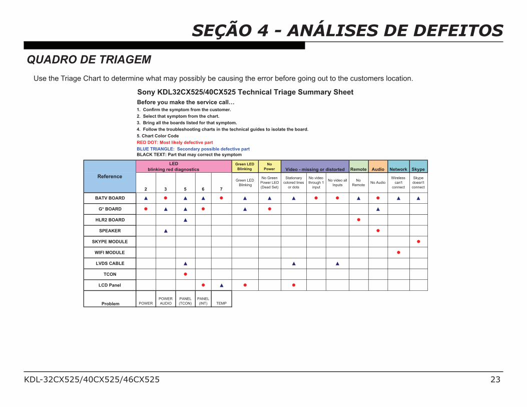
SEÇÃO 4 - ANÁLISES DE DEFEITOSQUADRO DE TRIAGEM
Use the Triage Chart to determine what may possibly be causing the error before going out to the customers location.
Before you make the service call…
Green LED
Blinking
No
Power Remote Audio Network Skype
2 3 5 6 7
Green LED
Blinking
No Green
Power LED
(Dead Set)
Stationary
colored lines
or dots
No video
through 1
input
No video all
Inputs
No
RemoteNo Audio
Wireless
can't
connect
Skype
doesn't
connect
BATV BOARD
G* BOARD
HLR2 BOARD ! ! !
SPEAKER ! !
SKYPE MODULE ! ! !
WIFI MODULE ! ! !
LVDS CABLE ! ! !
TCON ! ! !
LCD Panel
Problem POWER
POWER
AUDIO
PANEL
(TCON)
PANEL
(INT) TEMP
BLACK TEXT: Part that may correct the symptom
BLUE TRIANGLE: Secondary possible defective part
3. Bring all the boards listed for that symptom.
2. Select that symptom from the chart.
Reference
Sony KDL32CX525/40CX525 Technical Triage Summary Sheet
y p
LED
blinking red diagnostics
4. Follow the troubleshooting charts in the technical guides to isolate the board.
5. Chart Color Code
Video - missing or distorted
1. Confirm the symptom from the customer.
RED DOT: Most likely defective part
KDL-32CX525/40CX525/46CX525 24
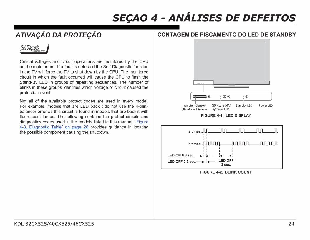
SEÇAO 4 - ANÁLISES DE DEFEITOSATIVAÇÃO DA PROTEÇÃO
Self DiagnosisSupported model
Critical voltages and circuit operations are monitored by the CPU
on the main board. If a fault is detected the Self-Diagnostic function
in the TV will force the TV to shut down by the CPU. The monitored
!" #!$% !&%'(! (% $()% *+#,$% - #"").%'!,,% +#/)% $()%012% $-%3+/(% $()%
Stand-By LED in groups of repeating sequences. The number of
4,!&5/%!&%$()/)%6"-#7/%!.)&$!8)/%'(! (%9-,$+6)%-"% !" #!$% +#/).%$()%
protection event.
Not all of the available protect codes are used in every model.
For example, models that are LED backlit do not use the 4-blink
balancer error as this circuit is found in models that are backlit with
3#-")/ )&$% ,+:7/;%<()% *-,,-'!&6% -&$+!&/% $()% 7"-$) $% !" #!$/% +&.%
diagnostics codes used in the models listed in this manual. “Figure
4-3. Diagnostic Table” on page 26 provides guidance in locating
the possible component causing the shutdown.
CONTAGEM DE PISCAMENTO DO LED DE STANDBY
Ambient Sensor/
(IR) Infrared Receiver
Picture Off /
Timer LED
Standby LED Power LED
FIGURE 4-1. LED DISPLAY
2 times
5 times
LED ON 0.3 sec.
LED OFF 0.3 sec. LED OFF
3 sec.
FIGURE 4-2. BLINK COUNT
KDL-32CX525/40CX525/46CX525 25
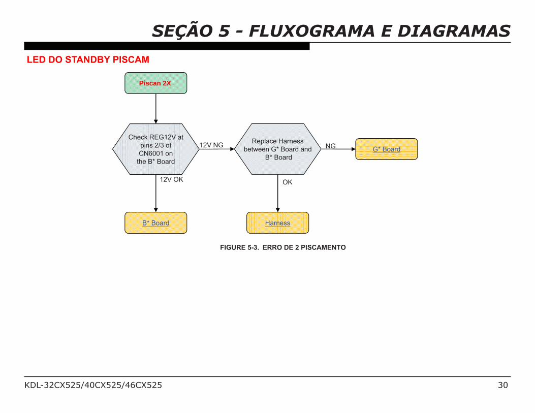
SEÇÃO 4 - ANÁLISES DE DEFEITOSPisca 2X - Erro do Fonte de Alimentação
A loss of REG12V from the power supply triggers this protect
event. This symptom is usually remedied by replacing the power
supply board. If the error continues after the power supply board
is replaced, suspect excessive loading which is causing the power
supply to shut down. This is usually caused by a failure of the inverter
circuits. Unplug the inverter and turn the TV back on. If a 6X error is
displayed, the inverter (or LCD panel) must be replaced.
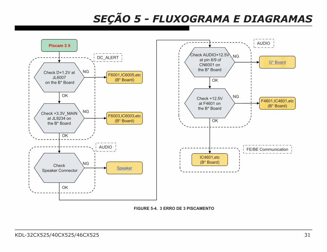
Pisca 3X - Regulador DC/Erro do Audio
<()%8"/$%$(!&6%$-% () 5%'()&%+%=>%4,!&5%7"-$) $!-&%:-.)%- #"/%!/%
the physical condition of the speakers and speaker connections. The
speakers should measure 8 ohms. Shorted speakers or connections
can cause a 3X blink protection mode.
If the speakers and connections check okay, then the defective
component is on the main board. Either an open F4200, defective
?0% @)6#,+$-"A% -"% .)*) $!9)% B#.!-% +:7,!8)"% '!,,% +#/)% +% =>% 4,!&5%
protection mode which would require replacing the main board.
A defect on the Power Supply Board may also cause a 3X blink
protection mode and shut-off. Check the AU12V level at CN6704/pin
14. If 0V is measure before shut-off the power supply board needs
to be replaced.
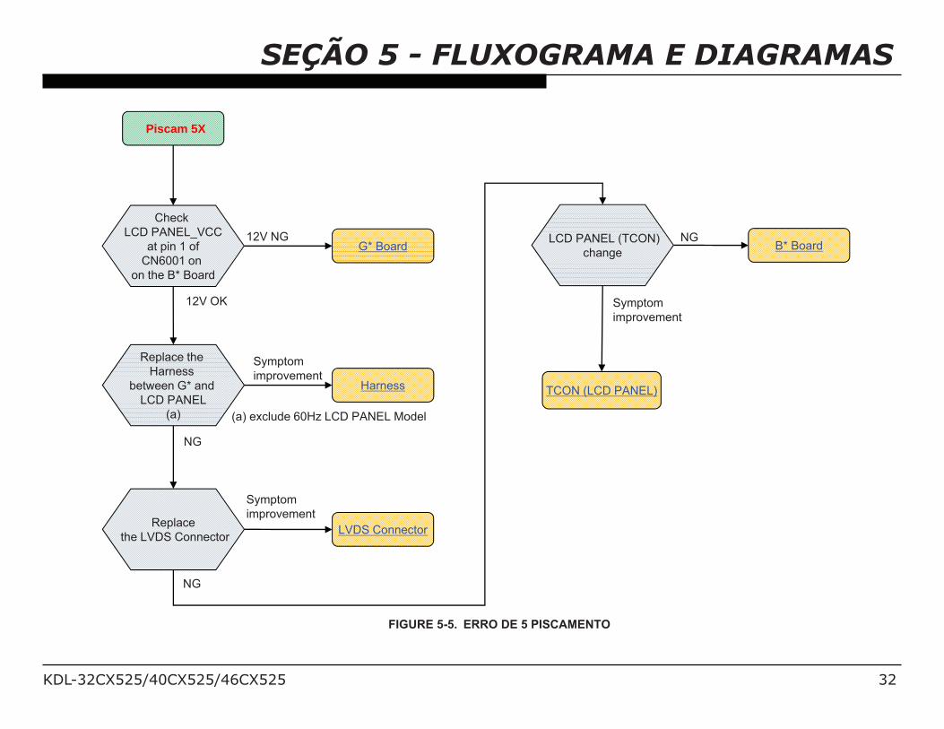
Pisca 5X - Erro do TCON
A communications error with the timing control circuits (TCON) has
occurred. If the TCON is available for replacement, replace the
TCON. If the TCON is not available, the LCD panel must be replaced
since the TCON circuit is part of the LCD panel assembly. In rare
cases a loose or defective LVDS cable could also be the cause.
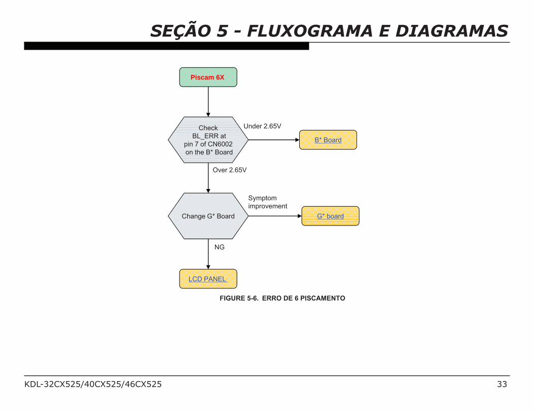
Pisca 6X - Falha de Sistema do Backlight
If the inverter circuits fails to generate high voltage or one or more
of the backlight lamps fails to light, the television will shut down
and display this diagnostics error. Observing for the presence of
backlighting is crucial in determining which component is likely at
fault.
If the backlights turn on before the 6X shutdown occurs, it is safe
to assume that the inverter circuits are functioning and one of the
lamps failed to ignite. Replacing the LCD panel is necessary. If the
backlights never turn on before the 6X shutdown, the inverter has
failed. If the inverter is available for replacement, replace the inverter.
If the inverter is not available, replace the LCD Panel.
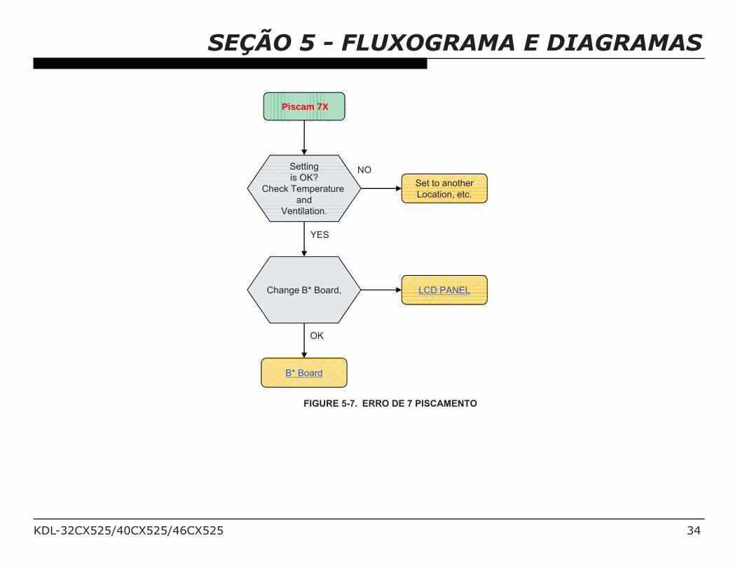
Pisca 7X - Falha da Temperatura
A digital thermometer IC located on the main board provides a
temperature reading of the chassis and LCD panel. If the temperature
exceeds a pre-determined point the TV will shut down. If this problem
occurs immediately at turn-on, the temperature sensing IC has failed
and replacing the main board is required. If this occurs after the TV
has been running for a while, check for ventilation issues that could
cause the TV to run hotter than normal.
KDL-32CX525/40CX525/46CX525 26
SEÇÃO 4 - ANÁLISES DE DEFEITOSDESCRIÇÃO DO CÓDIGO DE DIAGNÓSTICO
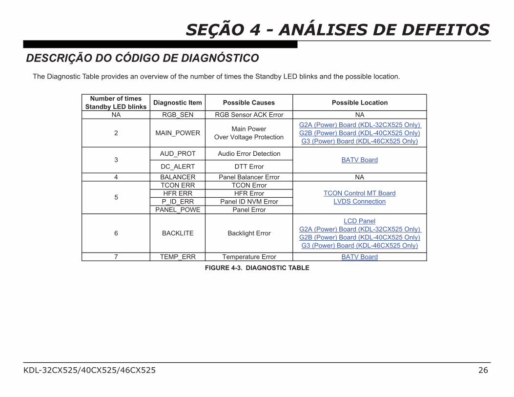
The Diagnostic Table provides an overview of the number of times the Standby LED blinks and the possible location.
Number of times
Standby LED blinksDiagnostic Item Possible Causes Possible Location
NA RGB_SEN RGB Sensor ACK Error NA
2 MAIN_POWERMain Power
Over Voltage Protection
G2A (Power) Board (KDL-32CX525 Only)
G2B (Power) Board (KDL-40CX525 Only)
G3 (Power) Board (KDL-46CX525 Only)
AUD_PROT Audio Error Detection
DC_ALERT DTT Error
4 BALANCER Panel Balancer Error NA
TCON ERR TCON Error
HFR ERR HFR Error
P_ID_ERR Panel ID NVM Error
PANEL_POWE Panel Error
6 BACKLITE Backlight Error
LCD Panel
G2A (Power) Board (KDL-32CX525 Only)
G2B (Power) Board (KDL-40CX525 Only)
G3 (Power) Board (KDL-46CX525 Only)
7 TEMP_ERR Temperature Error BATV Board
3
5
BATV Board
TCON Control MT Board
LVDS Connection
FIGURE 4-3. DIAGNOSTIC TABLE
KDL-32CX525/40CX525/46CX525 27
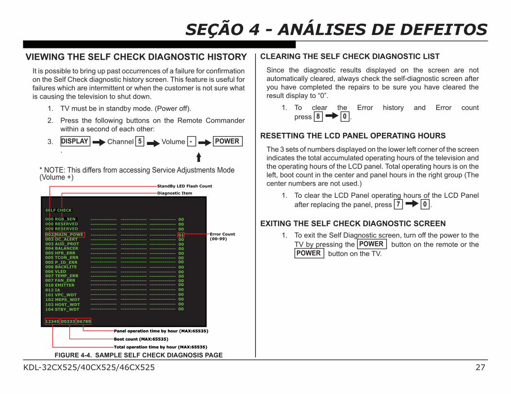
SEÇÃO 4 - ANÁLISES DE DEFEITOSVIEWING THE SELF CHECK DIAGNOSTIC HISTORY
C$%!/%7-//!4,)%$-%4"!&6%#7%7+/$%- #"")& )/%-*%+%*+!,#")%*-"% -&8":+$!-&%
on the Self Check diagnostic history screen. This feature is useful for
failures which are intermittent or when the customer is not sure what
is causing the television to shut down.
1. TV must be in standby mode. (Power off).
2. Press the following buttons on the Remote Commander
within a second of each other:
3. DISPLAY Channel 5 Volume - POWER
.
* NOTE: This differs from accessing Service Adjustments Mode (Volume +)
Total operation time by hour (MAX:65535)
Boot count (MAX:65535)
Panel operation time by hour (MAX:65535)
Total operation time by hour (MAX:65535)
Boot count (MAX:65535)
Panel operation time by hour (MAX:65535)
-------------- -------------- -------------- 01
-------------- -------------- -------------- 00
-------------- -------------- -------------- 00-------------- -------------- -------------- 00-------------- -------------- -------------- 00
-------------- -------------- -------------- 00
002 MAIN_POWE
003 DC_ALERT003 AUD_PROT004 BALANCER005 HFR_ERR
005 P_ID_ERR
12345-00333-0678912345-00333-06789- -
-------------- -------------- -------------- 00006 VLED
-------------- -------------- -------------- 00005 TCON_ERR-------------- -------------- -------------- 00
-------------- -------------- -------------- 00
-------------- -------------- -------------- 00
006 BACKLITE
007 TEMP_ERR
010 EMITTER-------------- -------------- -------------- 00007 FAN_ERR-------------- -------------- -------------- 00
012 IA -------------- -------------- -------------- 00
SELF CHECK
StandBy LED Flash Count
Diagnostic Item
Error Count (00-99)
-------------- -------------- -------------- 00
-------------- -------------- -------------- 00
101 VPC_WDT -------------- -------------- -------------- 00
102 MEPS_WDT -------------- -------------- -------------- 00
103 HOST_WDT -------------- -------------- -------------- 00
104 STBY_WDT -------------- -------------- -------------- 00
000 RGB_SEN
000 RESERVED
000 RESERVED
FIGURE 4-4. SAMPLE SELF CHECK DIAGNOSIS PAGE
CLEARING THE SELF CHECK DIAGNOSTIC LIST
Since the diagnostic results displayed on the screen are not
automatically cleared, always check the self-diagnostic screen after
you have completed the repairs to be sure you have cleared the
result display to “0”.
1. To clear the Error history and Error count
press 8 0 .
RESETTING THE LCD PANEL OPERATING HOURS
The 3 sets of numbers displayed on the lower left corner of the screen
indicates the total accumulated operating hours of the television and
the operating hours of the LCD panel. Total operating hours is on the
left, boot count in the center and panel hours in the right group (The
center numbers are not used.)
1. To clear the LCD Panel operating hours of the LCD Panel
after replacing the panel, press 7 0 .
EXITING THE SELF CHECK DIAGNOSTIC SCREEN
1. To exit the Self Diagnostic screen, turn off the power to the
TV by pressing the POWER button on the remote or the
POWER button on the TV.
KDL-32CX525/40CX525/46CX525 28
SEÇÃO 5 - FLUXOGRAMA E DIAGRAMAS
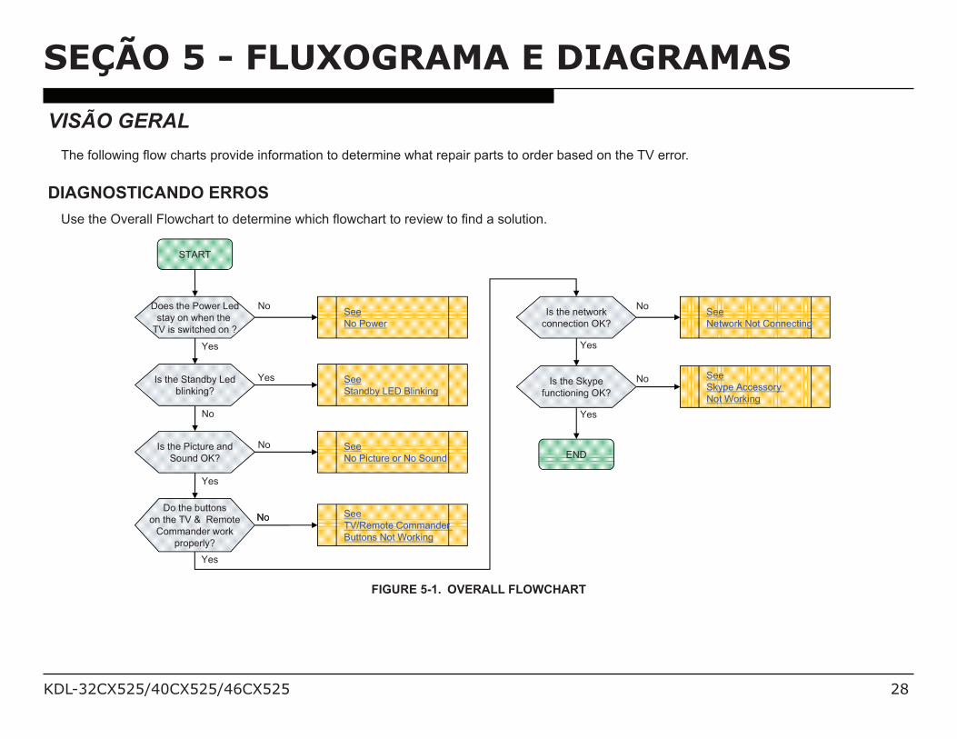
VISÃO GERAL
<()%*-,,-'!&6%3-'% (+"$/%7"-9!.)%!&*-":+$!-&%$-%.)$)":!&)%'(+$%")7+!"%7+"$/%$-%-".)"%4+/).%-&%$()%<D%)""-";
DIAGNOSTICANDO ERROS2/)%$()%E9)"+,,%F,-' (+"$%$-%.)$)":!&)%'(! (%3-' (+"$%$-%")9!)'%$-%8&.%+%/-,#$!-&;
START
Does the Power Led
stay on when the
TV is switched on ?
Is the Standby Led
blinking?
Is the Picture and
Sound OK? END
See
No Power
See
Standby LED Blinking
See
No Picture or No Sound
Is the network
connection OK?
See
Network Not Connecting
No
Yes
Yes
No
Yes
Do the buttons
on the TV & Remote
Commander work
properly?
See
TV/Remote Commander
Buttons Not Working
NoNo
Yes
No
Yes
No
See
Skype Accessory
Not Working
NoIs the Skype
functioning OK?
Yes
FIGURE 5-1. OVERALL FLOWCHART
KDL-32CX525/40CX525/46CX525 29
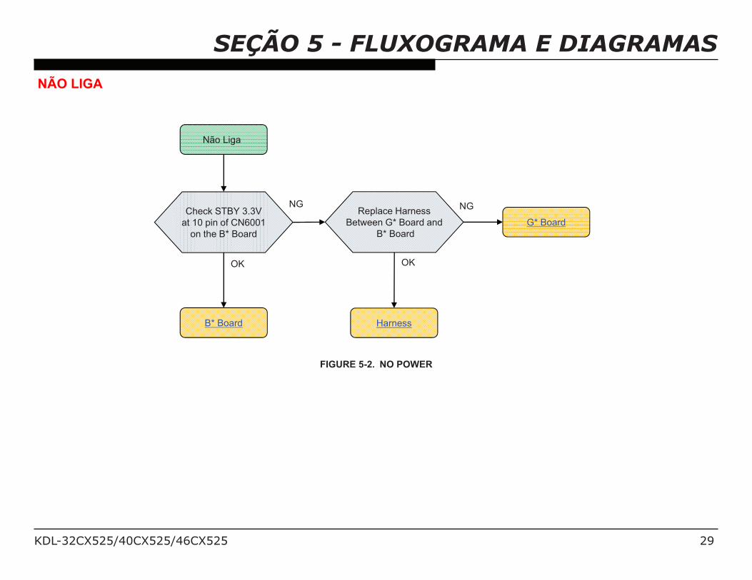
SEÇÃO 5 - FLUXOGRAMA E DIAGRAMASNÃO LIGA
Não Liga
Check STBY 3.3V
at 10 pin of CN6001
on the B* Board
Harness
G* Board
Replace Harness
Between G* Board and
B* Board
B* Board
NG
OK
NG
OK
FIGURE 5-2. NO POWER
KDL-32CX525/40CX525/46CX525 30
SEÇÃO 5 - FLUXOGRAMA E DIAGRAMASLED DO STANDBY PISCAM
Piscan 2X
Check REG12V at
pins 2/3 of
CN6001 on
the B* Board
B* Board Harness
G* Board
Replace Harness
between G* Board and
B* Board
12V NG
12V OK
NG
OK
FIGURE 5-3. ERRO DE 2 PISCAMENTO
KDL-32CX525/40CX525/46CX525 31
SEÇÃO 5 - FLUXOGRAMA E DIAGRAMAS
Piscam 3 X
Check D+1.2V at
JL6007
on the B* Board
F6001,IC6005,etc
(B* Board)
Speaker
Check +3.3V_MAIN
at JL9234 on
the B* Board
Check
Speaker Connector
F6003,IC6003,etc
(B* Board)
Check AUDIO+12.5V
at pin 8/9 of
CN6001 on
the B* Board
G* Board
Check +12.5V
at F4601 on
the B* Board
F4601,IC4601,etc
(B* Board)
IC4601,etc
(B* Board)
DC_ALERT
NG
OK
AUDIO
AUDIO
FE/BE Communication
NG
OK
NG
OK
NG
OK
NG
OK
FIGURE 5-4. 3 ERRO DE 3 PISCAMENTO
KDL-32CX525/40CX525/46CX525 32
SEÇÃO 5 - FLUXOGRAMA E DIAGRAMAS
Piscam 5X
Check
LCD PANEL_VCC
at pin 1 of
CN6001 on
on the B* Board
G* Board
Replace the
Harness
between G* and
LCD PANEL
(a)
Replace
the LVDS Connector
LCD PANEL (TCON)
changeB* Board
Harness
LVDS Connector
TCON (LCD PANEL)
(a) exclude 60Hz LCD PANEL Model
12V NG
12V OK
NG
Symptom
improvement
Symptom
improvement
Symptom
improvement
NG
NG
FIGURE 5-5. ERRO DE 5 PISCAMENTO
KDL-32CX525/40CX525/46CX525 33
SEÇÃO 5 - FLUXOGRAMA E DIAGRAMAS
Piscam 6X
Check
BL_ERR at
pin 7 of CN6002
on the B* Board
B* Board
Under 2.65V
G* board
NG
Over 2.65V
Symptom
improvement
Change G* Board
LCD PANEL
FIGURE 5-6. ERRO DE 6 PISCAMENTO
KDL-32CX525/40CX525/46CX525 34
SEÇÃO 5 - FLUXOGRAMA E DIAGRAMAS
Piscam 7X
Setting
is OK?
Check Temperature
and
Ventilation.
Set to another
Location, etc.
NO
YES
Change B* Board,
B* Board
OK
LCD PANEL
FIGURE 5-7. ERRO DE 7 PISCAMENTO
KDL-32CX525/40CX525/46CX525 35
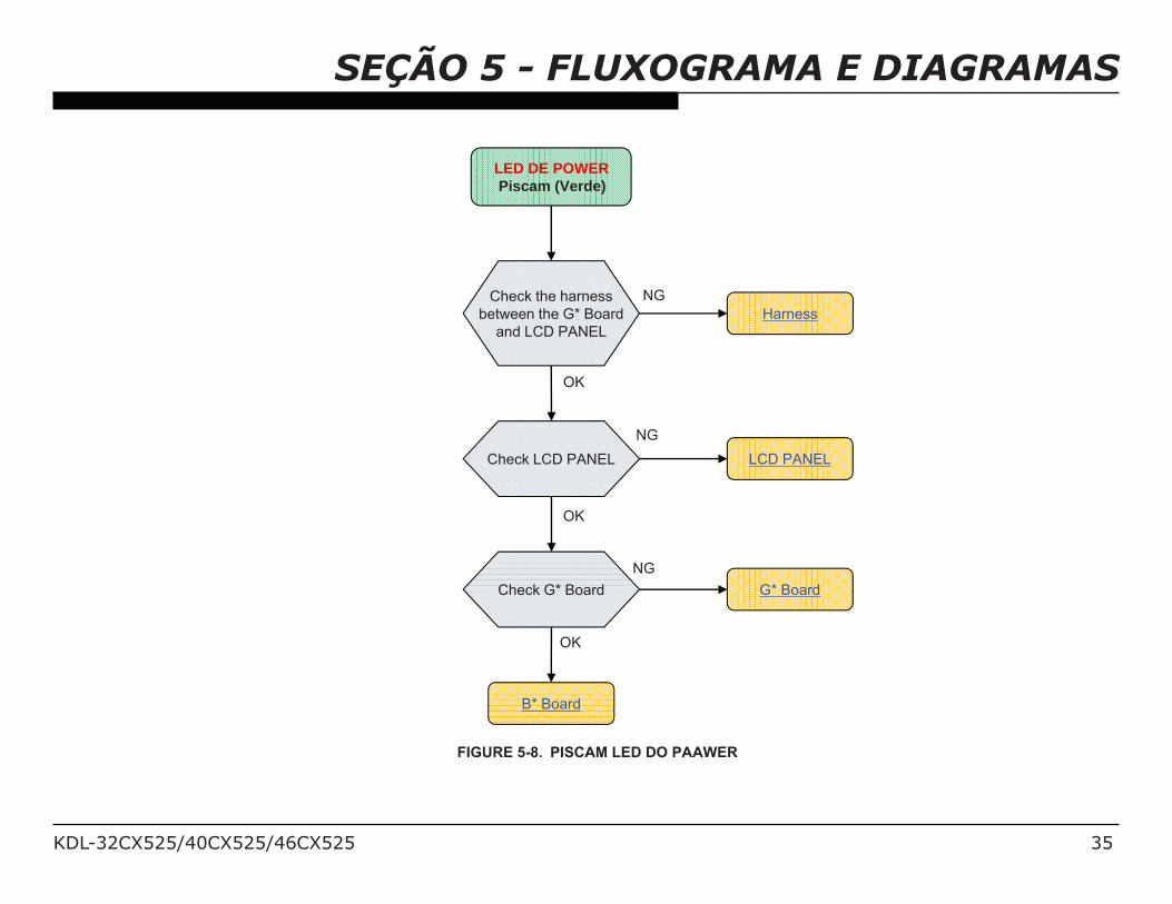
SEÇÃO 5 - FLUXOGRAMA E DIAGRAMAS
LED DE POWERPiscam (Verde)
OK
LCD PANEL
NG
Check LCD PANEL
Check the harness
between the G* Board
and LCD PANEL
Harness
NG
OK
Check G* Board
B* Board
OK
G* Board
NG
FIGURE 5-8. PISCAM LED DO PAAWER
KDL-32CX525/40CX525/46CX525 36
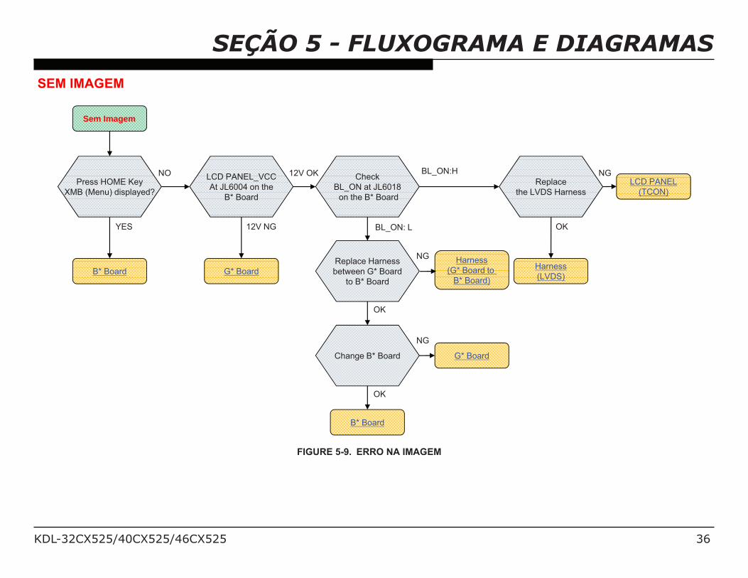
SEÇÃO 5 - FLUXOGRAMA E DIAGRAMASSEM IMAGEM
Sem Imagem
Press HOME Key
XMB (Menu) displayed?
B* Board
Replace
the LVDS Harness
LCD PANEL
(TCON)
Harness
(LVDS)
Check
BL_ON at JL6018
on the B* Board
BL_ON:H
B* Board
Replace Harness
between G* Board
to B* Board
Harness
(G* Board to
B* Board)
BL_ON: L
Change B* Board G* Board
NO
YES
NG
OK
NG
OK
NG
OK
LCD PANEL_VCC
At JL6004 on the
B* Board
G* Board
12V OK
12V NG
FIGURE 5-9. ERRO NA IMAGEM
KDL-32CX525/40CX525/46CX525 37
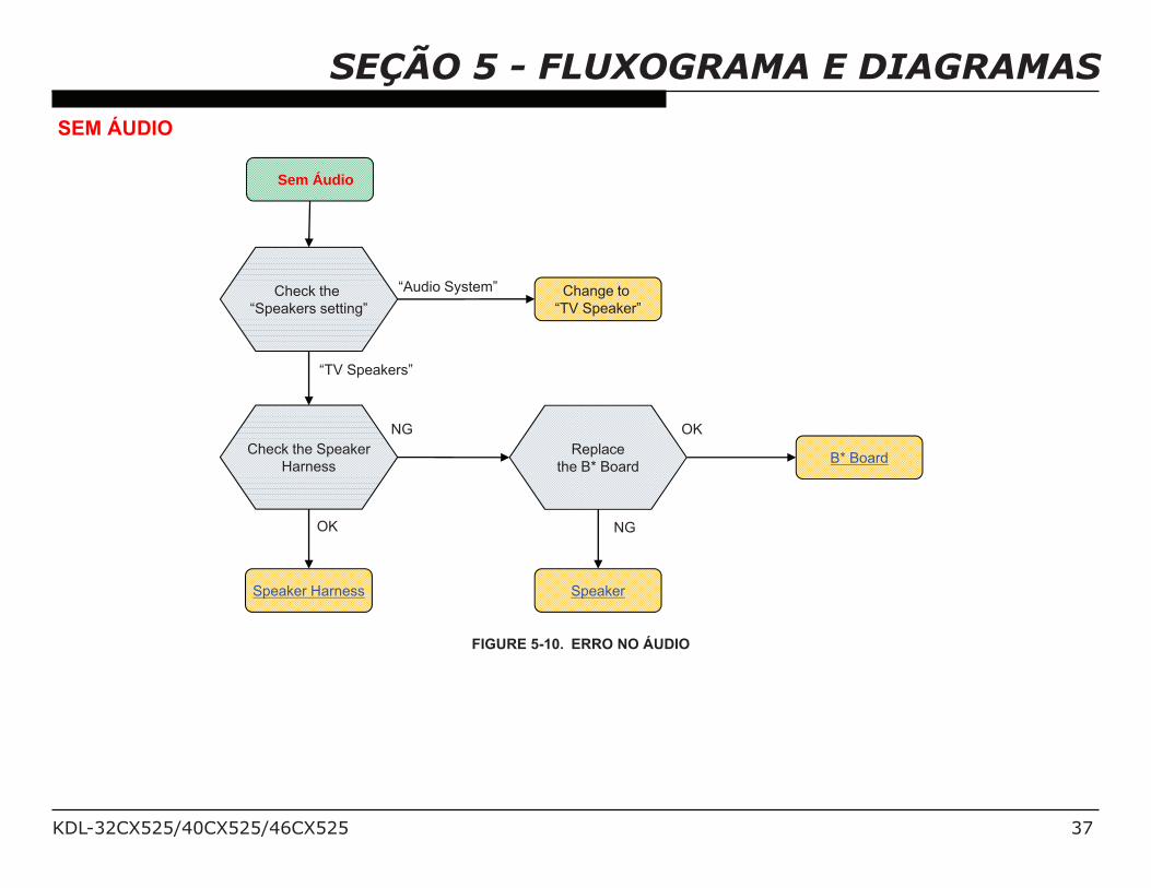
SEÇÃO 5 - FLUXOGRAMA E DIAGRAMASSEM ÁUDIO
Sem Áudio
Check the Speaker
Harness
Speaker Harness
Replace
the B* BoardB* Board
Speaker
OK
NG
NG
OK
Check the
“Speakers setting”
Change to
“TV Speaker”
“Audio System”
“TV Speakers”
FIGURE 5-10. ERRO NO ÁUDIO
KDL-32CX525/40CX525/46CX525 38
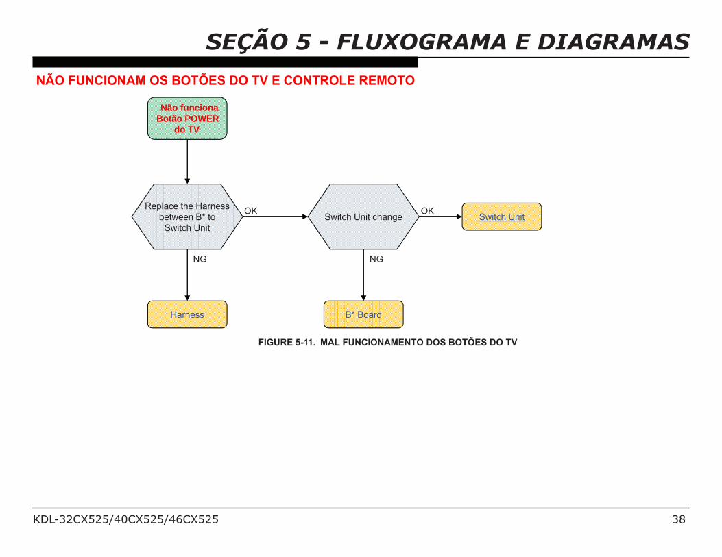
SEÇÃO 5 - FLUXOGRAMA E DIAGRAMASNÃO FUNCIONAM OS BOTÕES DO TV E CONTROLE REMOTO
Não funcionaBotão POWER
do TV
Replace the Harness
between B* to
Switch Unit
Switch Unit
Harness
Switch Unit change
B* Board
OK
NG
OK
NG
FIGURE 5-11. MAL FUNCIONAMENTO DOS BOTÕES DO TV
KDL-32CX525/40CX525/46CX525 39
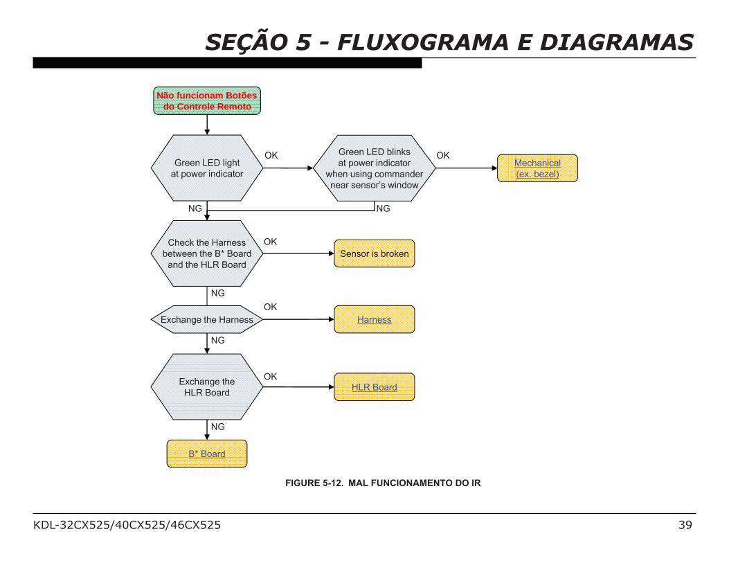
SEÇÃO 5 - FLUXOGRAMA E DIAGRAMAS
Não funcionam Botõesdo Controle Remoto
Green LED light
at power indicator
OK
NG
Sensor is broken
HLR Board
B* Board
OK
NG
Mechanical
(ex. bezel)
Green LED blinks
at power indicator
when using commander
near sensor’s window
Check the Harness
between the B* Board
and the HLR Board
Exchange the Harness
Exchange the
HLR Board
Harness
OK
NG
OK
OK
NG
NG
FIGURE 5-12. MAL FUNCIONAMENTO DO IR
KDL-32CX525/40CX525/46CX525 40
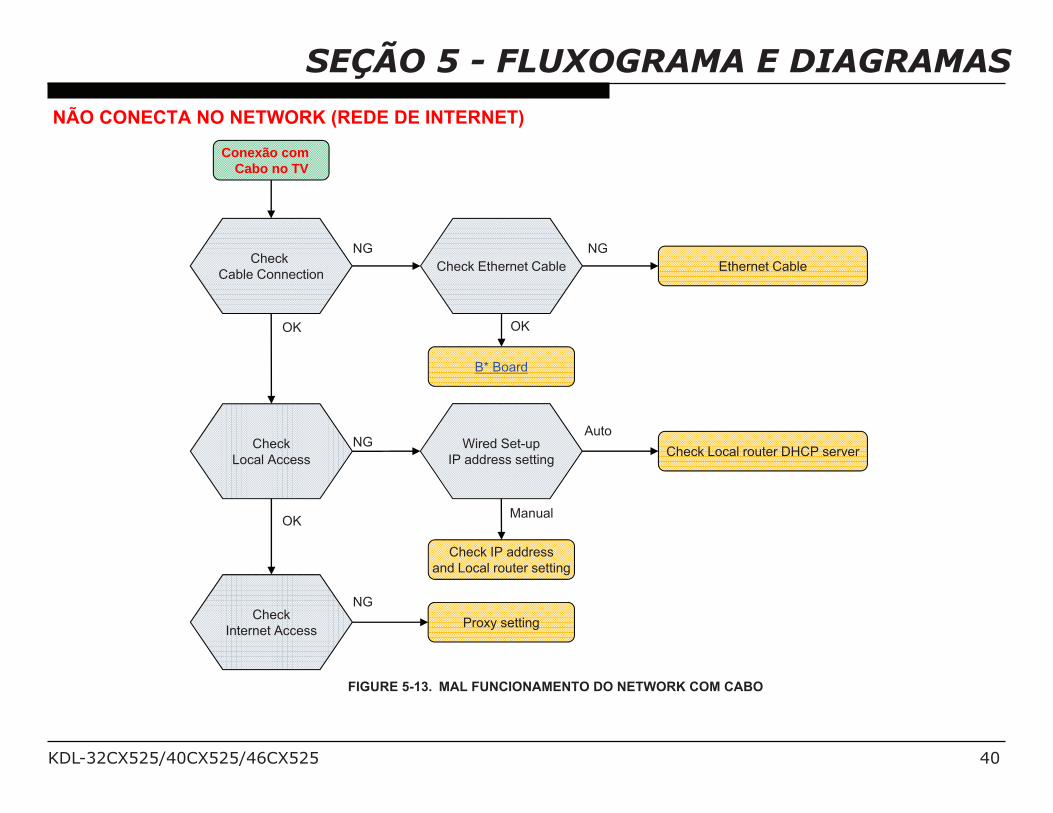
SEÇÃO 5 - FLUXOGRAMA E DIAGRAMASNÃO CONECTA NO NETWORK (REDE DE INTERNET)
Conexão com Cabo no TV
Check
Local Access
Check
Cable Connection
OK
NG
OK
NG
Check
Internet AccessProxy setting
NG
B* Board
Check Ethernet Cable Ethernet Cable
Check IP address
and Local router setting
Wired Set-up
IP address settingCheck Local router DHCP server
Auto
Manual
OK
NG
FIGURE 5-13. MAL FUNCIONAMENTO DO NETWORK COM CABO
KDL-32CX525/40CX525/46CX525 41
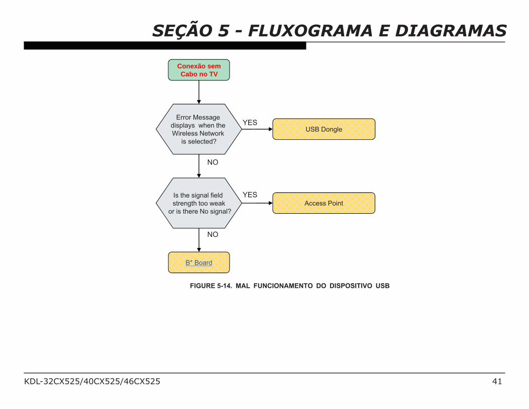
SEÇÃO 5 - FLUXOGRAMA E DIAGRAMAS
Conexão semCabo no TV
Is the signal field
strength too weak
or is there No signal?
Access Point
B* Board
Error Message
displays when the
Wireless Network
is selected?
USB Dongle
NO
YES
NO
YES
FIGURE 5-14. MAL FUNCIONAMENTO DO DISPOSITIVO USB
KDL-32CX525/40CX525/46CX525 42
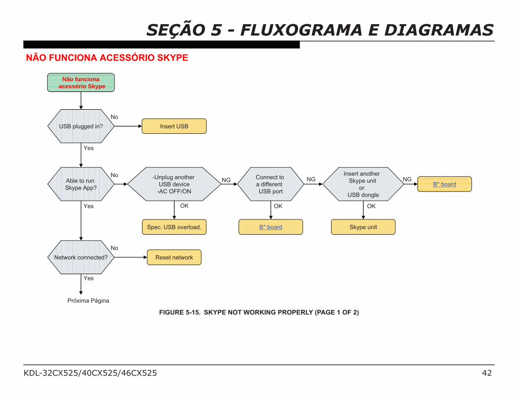
SEÇÃO 5 - FLUXOGRAMA E DIAGRAMASNÃO FUNCIONA ACESSÓRIO SKYPE
Não funcionaacessório Skype
USB plugged in? Insert USB
Able to run
Skype App?
Spec. USB overload.
Connect to
a different
USB port
B* board
Insert another
Skype unit
or
USB dongle
Skype unit
B* board
Network connected? Reset network
Yes
No
Yes
No
No
OK
NG
OK
NG
OK
NG
Próxima Página
Yes
-Unplug another
USB device
-AC OFF/ON
FIGURE 5-15. SKYPE NOT WORKING PROPERLY (PAGE 1 OF 2)
KDL-32CX525/40CX525/46CX525 43
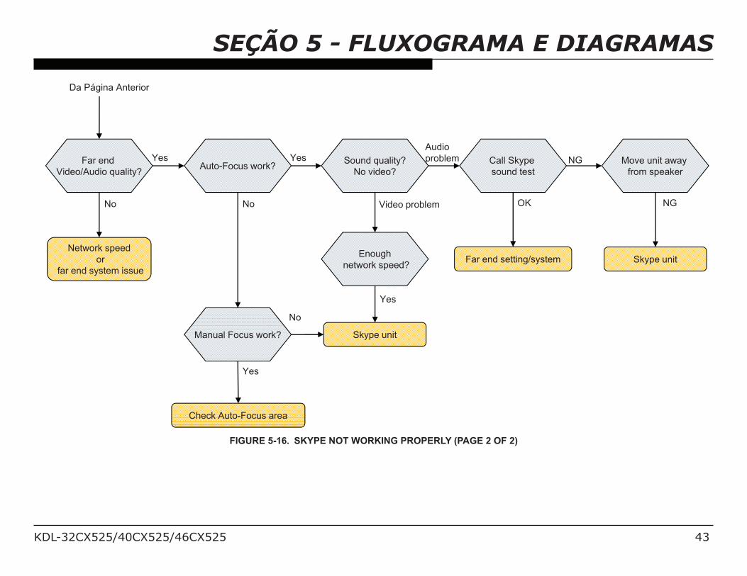
SEÇÃO 5 - FLUXOGRAMA E DIAGRAMAS
Far end
Video/Audio quality?
Network speed
or
far end system issue
Auto-Focus work?Sound quality?
No video?
Manual Focus work?
Check Auto-Focus area
Enough
network speed?
Skype unit
Call Skype
sound test
Far end setting/system
Move unit away
from speaker
Skype unit
Audio
problem
Video problem
Da Página Anterior
OK NG
Yes
No
Yes
No
No
Yes
Yes
NG
FIGURE 5-16. SKYPE NOT WORKING PROPERLY (PAGE 2 OF 2)
KDL-32CX525/40CX525/46CX525 44
!"#!$%$&'( $!&( )*%$&)+%*( ,-( .( #./&( $0",%/( !/(
description are not stocked because they are seldom
required for routine service.
The component parts of an assembly are indicated by the
reference numbers in the far right column of the parts list
and within the dotted lines of the diagram.
* Items marked with an asterisk are not stocked since
they are seldom required for routine service. Expect
some delay when ordering these components.
12345(36%( 7!"#!$%$&'( )*%$&)+%*(,-( '6.*)$8(
and ! mark are critical for safety. Replace only
9)&6(#./&($0",%/('#%7)+%*:(
12345(36%(7!"#!$%$&'()*%$&)+%*(,-(.(/%*(!0&;)$%(.$*(.( mark contain
7!$+*%$&).;()$<!/".&)!$:(=#%7)+7()$'&/07&)!$'("0'&(,%(.*6%/%*(&!(96%$%>%/(
these components are repaired and/or replaced.
See Appendix A: Encryption Key Components in the back of this manual.
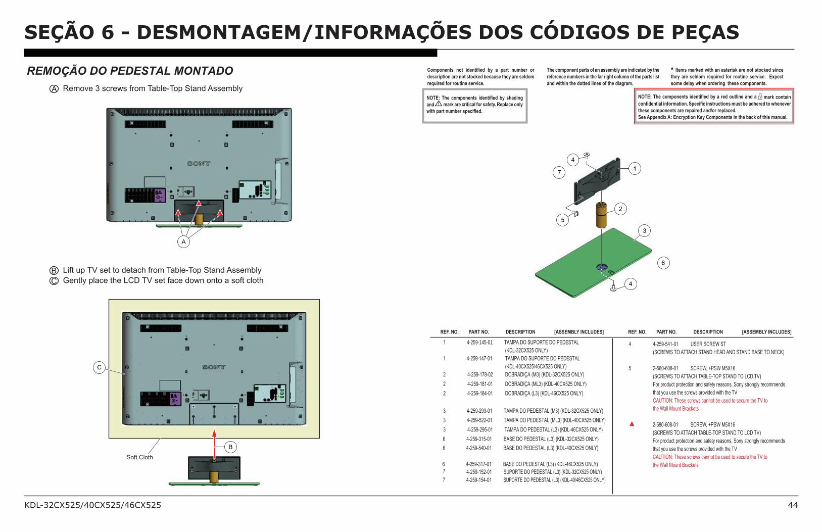
REMOÇÃO DO PEDESTAL MONTADO
A Remove 3 screws from Table-Top Stand Assembly
REF. NO. PART NO. DESCRIPTION [ASSEMBLY INCLUDES] REF. NO. PART NO. DESCRIPTION [ASSEMBLY INCLUDES]
1 4-259-145-01 TAMPA DO SUPORTE DO PEDESTAL (KDL-32CX525 ONLY)
1 4-259-147-01 TAMPA DO SUPORTE DO PEDESTAL (KDL-40CX525/46CX525 ONLY)
2 4-259-178-02 DOBRADIÇA (M3) (KDL-32CX525 ONLY) 2 4-259-181-01 DOBRADIÇA (ML3) (KDL-40CX525 ONLY)
2 4-259-184-01 DOBRADIÇA (L3) (KDL-46CX525 ONLY)
3 4-259-293-01 TAMPA DO PEDESTAL (M3) (KDL-32CX525 ONLY)
6 4-259-315-01 BASE DO PEDESTAL (L3) (KDL-32CX525 ONLY)
3 4-259-522-01 TAMPA DO PEDESTAL (ML3) (KDL-40CX525 ONLY)
3 4-259-295-01 TAMPA DO PEDESTAL (L3) (KDL-46CX525 ONLY)
7 4-259-152-01 SUPORTE DO PEDESTAL (L3) (KDL-32CX525 ONLY)
4 4-259-541-01 USER SCREW ST
(SCREWS TO ATTACH STAND HEAD AND STAND BASE TO NECK)
5 2-580-608-01 SCREW, +PSW M5X16
(SCREWS TO ATTACH TABLE-TOP STAND TO LCD TV)
For product protection and safety reasons, Sony strongly recommends
that you use the screws provided with the TV
CAUTION: These screws cannot be used to secure the TV to
the Wall Mount Brackets
2-580-608-01 SCREW, +PSW M5X16
(SCREWS TO ATTACH TABLE-TOP STAND TO LCD TV)
For product protection and safety reasons, Sony strongly recommends
that you use the screws provided with the TV
CAUTION: These screws cannot be used to secure the TV to
the Wall Mount Brackets
B Lift up TV set to detach from Table-Top Stand Assembly
C Gently place the LCD TV set face down onto a soft cloth
C
Soft Cloth
B
1
2
3
5
4
4
SEÇÃO 6 - DESMONTAGEM/INFORMAÇÕES DOS CÓDIGOS DE PEÇAS
A
6 4-259-540-01 BASE DO PEDESTAL (L3) (KDL-40CX525 ONLY)
6 4-259-317-01 BASE DO PEDESTAL (L3) (KDL-46CX525 ONLY)
7 4-259-154-01 SUPORTE DO PEDESTAL (L3) (KDL-40/46CX525 ONLY)
6
7
Teruaki_Nakagawa
Teruaki_Nakagawa
KDL-32CX525/40CX525/46CX525 45
SEÇÃO 6 - DESMONTAGEM/INFORMAÇÕES DOS CÓDIGOS DE PEÇAS12345(36%( 7!"#!$%$&'( )*%$&)+%*(,-( '6.*)$8(
and ! mark are critical for safety. Replace only
9)&6(#./&($0",%/('#%7)+%*:(
12345(36%(7!"#!$%$&'()*%$&)+%*(,-(.(/%*(!0&;)$%(.$*(.( mark contain
7!$+*%$&).;()$<!/".&)!$:(=#%7)+7()$'&/07&)!$'("0'&(,%(.*6%/%*(&!(96%$%>%/(
these components are repaired and/or replaced.
See Appendix A: Encryption Key Components in the back of this manual.
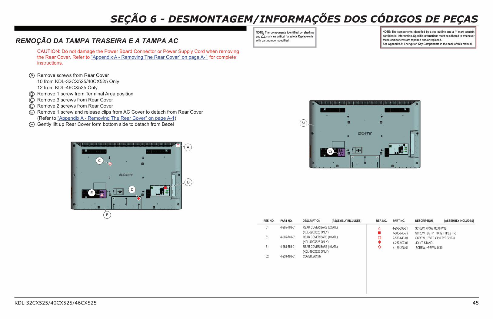
REF. NO. PART NO. DESCRIPTION [ASSEMBLY INCLUDES] REF. NO. PART NO. DESCRIPTION [ASSEMBLY INCLUDES]
51 4-265-768-01 REAR COVER BARE (32 ATL)
(KDL-32CX525 ONLY)
51 4-265-769-01 REAR COVER BARE (40 ATL)
(KDL-40CX525 ONLY)
51 4-268-556-01 REAR COVER BARE (46 ATL)
(KDL-46CX525 ONLY)
52 4-259-168-01 COVER, AC(M)
4-256-393-01 SCREW, +PSW M3X6 W12
7-685-648-79 SCREW +BVTP 3X12 TYPE2 IT-3
2-580-640-01 SCREW, +BVTP 4X16 TYPE2 IT-3
4-257-907-01 JOINT, STAND
4-159-298-01 SCREW, +PSW M4X10
REMOÇÃO DA TAMPA TRASEIRA E A TAMPA AC CAUTION: Do not damage the Power Board Connector or Power Supply Cord when removing
the Rear Cover. Refer to “Appendix A - Removing The Rear Cover” on page A-1 for complete
instructions.
A Remove screws from Rear Cover
10 from KDL-32CX525/40CX525 Only
12 from KDL-46CX525 Only
B Remove 1 screw from Terminal Area position
C Remove 3 screws from Rear Cover
D Remove 2 screws from Rear Cover
E Remove 1 screw and release clips from AC Cover to detach from Rear Cover
(Refer to “Appendix A - Removing The Rear Cover” on page A-1)
F Gently lift up Rear Cover form bottom side to detach from Bezel
E
C
D
A
F
B
52
51
KDL-32CX525/40CX525/46CX525 46
SEÇÃO 6 - DESMONTAGEM/INFORMAÇÕES DOS CÓDIGOS DE PEÇAS12345(36%( 7!"#!$%$&'( )*%$&)+%*(,-( '6.*)$8(
and ! mark are critical for safety. Replace only
9)&6(#./&($0",%/('#%7)+%*:(
12345(36%(7!"#!$%$&'()*%$&)+%*(,-(.(/%*(!0&;)$%(.$*(.( mark contain
7!$+*%$&).;()$<!/".&)!$:(=#%7)+7()$'&/07&)!$'("0'&(,%(.*6%/%*(&!(96%$%>%/(
these components are repaired and/or replaced.
See Appendix A: Encryption Key Components in the back of this manual.
REF. NO. PART NO. DESCRIPTION [ASSEMBLY INCLUDES] REF. NO. PART NO. DESCRIPTION [ASSEMBLY INCLUDES]
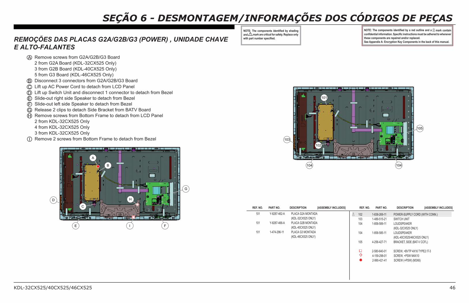
101 Y-8287-462-A PLACA G2A MONTADA (KDL-32CX525 ONLY)
101 Y-8287-466-A PLACA G2B MONTADA (KDL-40CX525 ONLY)
101 1-474-296-11 PLACA G3 MONTADA (KDL-46CX525 ONLY)
! 102 1-838-269-11 POWER-SUPPLY CORD (WITH CONN.)
103 1-489-515-21 SWITCH UNIT
104 1-858-589-11 LOUDSPEAKER
(KDL-32CX525 ONLY)
104 1-858-585-11 LOUDSPEAKER
(KDL-40CX525/46CX525 ONLY)
105 4-256-427-71 BRACKET, SIDE (BAT-V CCFL)
2-580-640-01 SCREW, +BVTP 4X16 TYPE2 IT-3
4-159-298-01 SCREW, +PSW M4X10
2-990-421-41 SCREW (+PSW) (M3X6)
REMOÇÕES DAS PLACAS G2A/G2B/G3 (POWER) , UNIDADE CHAVE
E ALTO-FALANTES
A Remove screws from G2A/G2B/G3 Board
2 from G2A Board (KDL-32CX525 Only)
3 from G2B Board (KDL-40CX525 Only)
5 from G3 Board (KDL-46CX525 Only)
B Disconnect 3 connectors from G2A/G2B/G3 Board
C Lift up AC Power Cord to detach from LCD Panel
D Lift up Switch Unit and disconnect 1 connector to detach from Bezel
E Slide-out right side Speaker to detach from Bezel
F Slide-out left side Speaker to detach from Bezel
G Release 2 clips to detach Side Bracket from BATV Board
H Remove screws from Bottom Frame to detach from LCD Panel
2 from KDL-32CX525 Only
4 from KDL-32CX525 Only
3 from KDL-32CX525 Only
I Remove 2 screws from Bottom Frame to detach from Bezel
A
B
C
D
E F
G
H
I
101
102
103
104 104
105
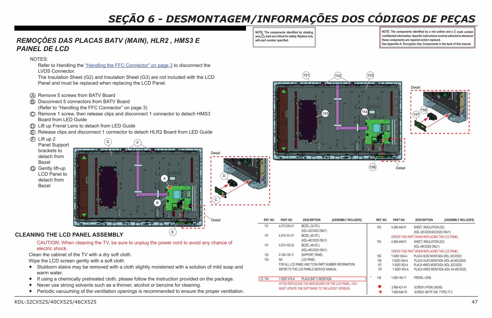
KDL-32CX525/40CX525/46CX525 47
SEÇÃO 6 - DESMONTAGEM/INFORMAÇÕES DOS CÓDIGOS DE PEÇAS12345(36%( 7!"#!$%$&'( )*%$&)+%*(,-( '6.*)$8(
and ! mark are critical for safety. Replace only
9)&6(#./&($0",%/('#%7)+%*:(
12345(36%(7!"#!$%$&'()*%$&)+%*(,-(.(/%*(!0&;)$%(.$*(.( mark contain
7!$+*%$&).;()$<!/".&)!$:(=#%7)+7()$'&/07&)!$'("0'&(,%(.*6%/%*(&!(96%$%>%/(
these components are repaired and/or replaced.
See Appendix A: Encryption Key Components in the back of this manual. REMOÇÕES DAS PLACAS BATV (MAIN), HLR2 , HMS3 EPAINEL DE LCD
NOTES:
Refer to Handling the “Handling the FFC Connector” on page 3 to disconnect the
LVDS Connector.
The Insulation Sheet (G2) and Insulation Sheet (G3) are not included with the LCD
Panel and must be replaced when replacing the LCD Panel.
A Remove 5 screws from BATV Board
B Disconnect 5 connectors from BATV Board
(Refer to “Handling the FFC Connector” on page 3)
C Remove 1 screw, then release clips and disconnect 1 connector to detach HMS3
Board from LED Guide
D Lift up Frenel Lens to detach from LED Guide
E Release clips and disconnect 1 connector to detach HLR2 Board from LED Guide
151 4-273-254-01 BEZEL (32 ATL)
(KDL-32CX525 ONLY)
151 4-274-101-01 BEZEL (40 ATL)
(KDL-40CX525 ONLY)
151 4-274-102-02 BEZEL (46 ATL)
(KDL-46CX525 ONLY)
152 4-166-126-11 SUPPORT, PANEL
153 NA LCD PANEL
FOR ALL LCD PANEL AND TCON PART NUMBER INFORMATION
REFER TO THE LCD PANELS SERVICE MANUAL
154 Y-8287-474-A PLACA BAT-V MONTADA AFTER REPLACING THE MAIN BOARD OR THE LCD PANEL, YOU
MUST UPDATE THE SOFTWARE TO THE LATEST VERSION.
REF. NO. PART NO. DESCRIPTION [ASSEMBLY INCLUDES] REF. NO. PART NO. DESCRIPTION [ASSEMBLY INCLUDES]
155 4-268-448-01 SHEET, INSULATION (G2)
(KDL-32CX525/40CX525 ONLY)
ORDER THIS PART WHEN REPLACING THE LCD PANEL.
155 4-268-449-01 SHEET, INSULATION (G3)
(KDL-46CX525 ONLY)
ORDER THIS PART WHEN REPLACING THE LCD PANEL.
156 Y-8287-504-A PLACA HLR2 MONTADA (KDL-32CX525)
157 Y-8287-503-A PLACA HMS3 MONTADA (KDL-32CX525)
* 158 1-856-184-11 FRENEL LENS
2-990-421-41 SCREW (+PSW) (M3X6)
7-685-646-79 SCREW +BVTP 3X8 TYPE2 IT-3
Detail
157
158154
153151 152
156
155
Detail
CLEANING THE LCD PANEL ASSEMBLY
CAUTION: When cleaning the TV, be sure to unplug the power cord to avoid any chance of
electric shock.
Clean the cabinet of the TV with a dry soft cloth.
Wipe the LCD screen gently with a soft cloth.
!Stubborn stains may be removed with a cloth slightly moistened with a solution of mild soap and
warm water.
!If using a chemically pretreated cloth, please follow the instruction provided on the package.
!Never use strong solvents such as a thinner, alcohol or benzine for cleaning.
!Periodic vacuuming of the ventilation openings is recommended to ensure the proper ventilation.
Detail
A
B
E
G F
Detail
C
D
F Lift up 2
Panel Support
brackets to
detach from
Bezel
G Gently lift-up
LCD Panel to
detach from
Bezel
156 Y-8287-454-A PLACA HLR2 MONTADA (KDL-40-46CX525)
157 Y-8287-453-A PLACA HMS3 MONTADA (KDL-40-46CX525)
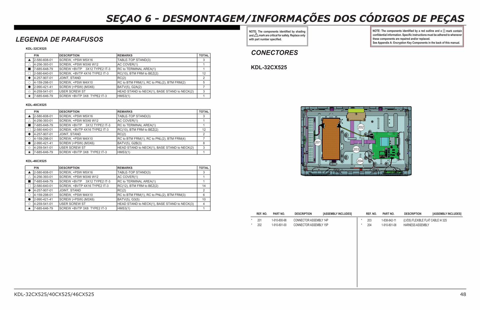
KDL-32CX525/40CX525/46CX525 48
SEÇAO 6 - DESMONTAGEM/INFORMAÇÕES DOS CÓDIGOS DE PEÇAS12345(36%( 7!"#!$%$&'( )*%$&)+%*(,-( '6.*)$8(
and ! mark are critical for safety. Replace only
9)&6(#./&($0",%/('#%7)+%*:(
12345(36%(7!"#!$%$&'()*%$&)+%*(,-(.(/%*(!0&;)$%(.$*(.( mark contain
7!$+*%$&).;()$<!/".&)!$:(=#%7)+7()$'&/07&)!$'("0'&(,%(.*6%/%*(&!(96%$%>%/(
these components are repaired and/or replaced.
See Appendix A: Encryption Key Components in the back of this manual.
* 201 1-910-800-98 CONNECTOR ASSEMBLY 14P
* 202 1-910-801-00 CONNECTOR ASSEMBLY 15P
REF. NO. PART NO. DESCRIPTION [ASSEMBLY INCLUDES] REF. NO. PART NO. DESCRIPTION [ASSEMBLY INCLUDES]
* 203 1-838-842-11 (LVDS) FLEXIBLE FLAT CABLE I4 32S
* 204 1-910-801-08 HARNESS ASSEMBLY
LEGENDA DE PARAFUSOS
CONECTORES
KDL-32CX525
202
204
203
201
P/N DESCRIPTION REMARKS TOTAL
▲ 2-580-608-01 SCREW, +PSW M5X16 TABLE-TOP STAND(3) 3
△ 4-256-393-01 SCREW, +PSW M3X6 W12 AC COVER(1) 1
■ 7-685-648-79 SCREW +BVTP 3X12 TYPE2 IT-3 RC to TERMINAL AREA(1) 1
□ 2-580-640-01 SCREW, +BVTP 4X16 TYPE2 IT-3 RC(10), BTM FRM to BEZ(2) 12
◆ 4-257-907-01 JOINT, STAND RC(2) 2
◇ 4-159-298-01 SCREW, +PSW M4X10 RC to BTM FRM(1), RC to PNL(2), BTM FRM(2) 5
● 2-990-421-41 SCREW (+PSW) (M3X6) BATV(5), G2A(2) 7
☆ 4-259-541-01 USER SCREW ST HEAD STAND to NECK(1), BASE STAND to NECK(2) 3
★ 7-685-646-79 SCREW +BVTP 3X8 TYPE2 IT-3 HMS3(1) 1
P/N DESCRIPTION REMARKS TOTAL
▲ 2-580-608-01 SCREW, +PSW M5X16 TABLE-TOP STAND(3) 3
△ 4-256-393-01 SCREW, +PSW M3X6 W12 AC COVER(1) 1
■ 7-685-648-79 SCREW +BVTP 3X12 TYPE2 IT-3 RC to TERMINAL AREA(1) 1
□ 2-580-640-01 SCREW, +BVTP 4X16 TYPE2 IT-3 RC(10), BTM FRM to BEZ(2) 12
◆ 4-257-907-01 JOINT, STAND RC(2) 2
◇ 4-159-298-01 SCREW, +PSW M4X10 RC to BTM FRM(1), RC to PNL(2), BTM FRM(4) 7
● 2-990-421-41 SCREW (+PSW) (M3X6) BATV(5), G2B(3) 8
☆ 4-259-541-01 USER SCREW ST HEAD STAND to NECK(1), BASE STAND to NECK(2) 3
★ 7-685-646-79 SCREW +BVTP 3X8 TYPE2 IT-3 HMS3(1) 1
P/N DESCRIPTION REMARKS TOTAL
▲ 2-580-608-01 SCREW, +PSW M5X16 TABLE-TOP STAND(3) 3
△ 4-256-393-01 SCREW, +PSW M3X6 W12 AC COVER(1) 1
■ 7-685-648-79 SCREW +BVTP 3X12 TYPE2 IT-3 RC to TERMINAL AREA(1) 1
□ 2-580-640-01 SCREW, +BVTP 4X16 TYPE2 IT-3 RC(12), BTM FRM to BEZ(2) 14
◆ 4-257-907-01 JOINT, STAND RC(2) 2
◇ 4-159-298-01 SCREW, +PSW M4X10 RC to BTM FRM(1), RC to PNL(2), BTM FRM(3) 6
● 2-990-421-41 SCREW (+PSW) (M3X6) BATV(5), G3(5) 10
☆ 4-259-541-01 USER SCREW ST HEAD STAND to NECK(1), BASE STAND to NECK(3) 4
★ 7-685-646-79 SCREW +BVTP 3X8 TYPE2 IT-3 HMS3(1) 1
KDL-32CX525
KDL-40CX525
KDL-46CX525
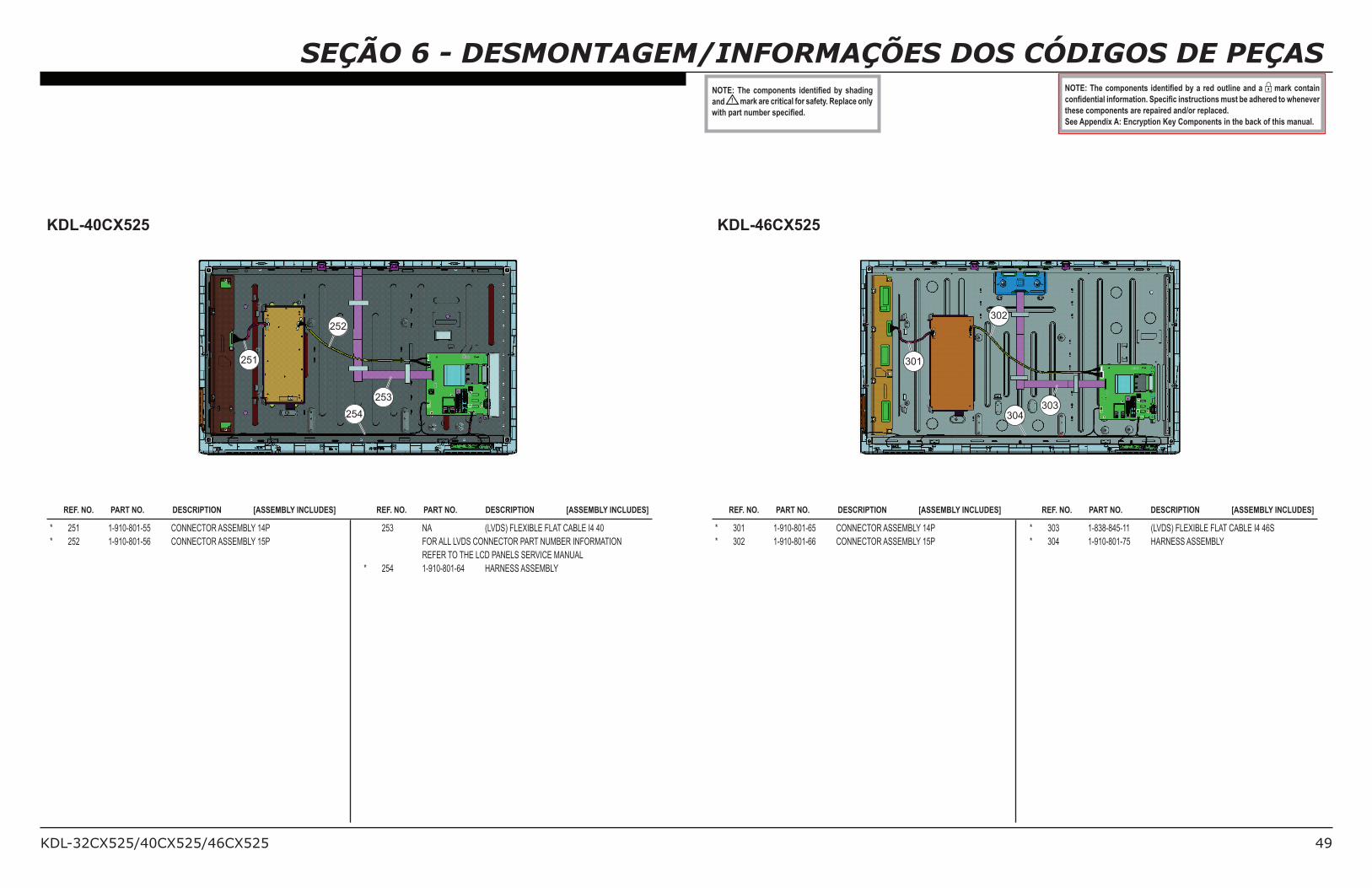
KDL-32CX525/40CX525/46CX525 49
SEÇÃO 6 - DESMONTAGEM/INFORMAÇÕES DOS CÓDIGOS DE PEÇAS12345(36%( 7!"#!$%$&'( )*%$&)+%*(,-( '6.*)$8(
and ! mark are critical for safety. Replace only
9)&6(#./&($0",%/('#%7)+%*:(
12345(36%(7!"#!$%$&'()*%$&)+%*(,-(.(/%*(!0&;)$%(.$*(.( mark contain
7!$+*%$&).;()$<!/".&)!$:(=#%7)+7()$'&/07&)!$'("0'&(,%(.*6%/%*(&!(96%$%>%/(
these components are repaired and/or replaced.
See Appendix A: Encryption Key Components in the back of this manual.
REF. NO. PART NO. DESCRIPTION [ASSEMBLY INCLUDES] REF. NO. PART NO. DESCRIPTION [ASSEMBLY INCLUDES] REF. NO. PART NO. DESCRIPTION [ASSEMBLY INCLUDES] REF. NO. PART NO. DESCRIPTION [ASSEMBLY INCLUDES]
KDL-40CX525 KDL-46CX525
* 251 1-910-801-55 CONNECTOR ASSEMBLY 14P
* 252 1-910-801-56 CONNECTOR ASSEMBLY 15P
253 NA (LVDS) FLEXIBLE FLAT CABLE I4 40
FOR ALL LVDS CONNECTOR PART NUMBER INFORMATION
REFER TO THE LCD PANELS SERVICE MANUAL
* 254 1-910-801-64 HARNESS ASSEMBLY
* 301 1-910-801-65 CONNECTOR ASSEMBLY 14P
* 302 1-910-801-66 CONNECTOR ASSEMBLY 15P
* 303 1-838-845-11 (LVDS) FLEXIBLE FLAT CABLE I4 46S
* 304 1-910-801-75 HARNESS ASSEMBLY
302
304
303
301
252
254
253
251
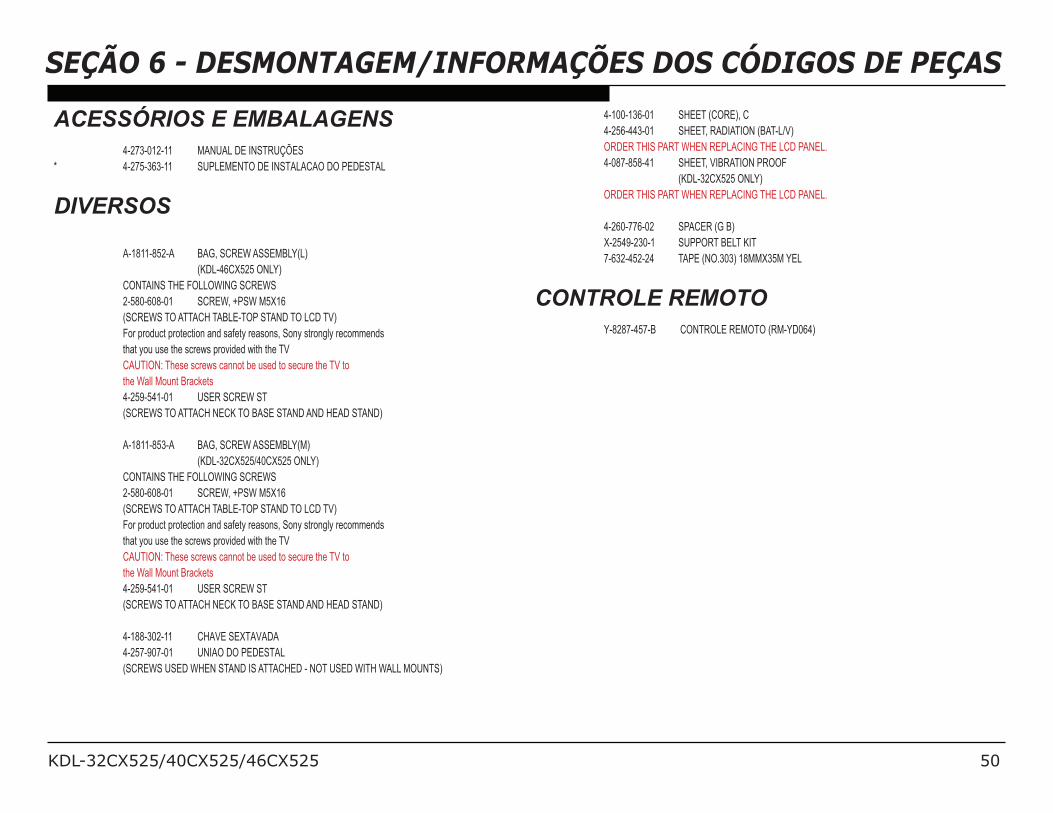
KDL-32CX525/40CX525/46CX525 50
SEÇÃO 6 - DESMONTAGEM/INFORMAÇÕES DOS CÓDIGOS DE PEÇAS
ACESSÓRIOS E EMBALAGENS 4-273-012-11 MANUAL DE INSTRUÇÕES* 4-275-363-11 SUPLEMENTO DE INSTALACAO DO PEDESTAL
DIVERSOS
A-1811-852-A BAG, SCREW ASSEMBLY(L)
(KDL-46CX525 ONLY)
CONTAINS THE FOLLOWING SCREWS
2-580-608-01 SCREW, +PSW M5X16
(SCREWS TO ATTACH TABLE-TOP STAND TO LCD TV)
For product protection and safety reasons, Sony strongly recommends
that you use the screws provided with the TV
CAUTION: These screws cannot be used to secure the TV to
the Wall Mount Brackets
4-259-541-01 USER SCREW ST
(SCREWS TO ATTACH NECK TO BASE STAND AND HEAD STAND)
A-1811-853-A BAG, SCREW ASSEMBLY(M)
(KDL-32CX525/40CX525 ONLY)
CONTAINS THE FOLLOWING SCREWS
2-580-608-01 SCREW, +PSW M5X16
(SCREWS TO ATTACH TABLE-TOP STAND TO LCD TV)
For product protection and safety reasons, Sony strongly recommends
that you use the screws provided with the TV
CAUTION: These screws cannot be used to secure the TV to
the Wall Mount Brackets
4-259-541-01 USER SCREW ST
(SCREWS TO ATTACH NECK TO BASE STAND AND HEAD STAND)
4-188-302-11 CHAVE SEXTAVADA 4-257-907-01 UNIAO DO PEDESTAL (SCREWS USED WHEN STAND IS ATTACHED - NOT USED WITH WALL MOUNTS)
4-100-136-01 SHEET (CORE), C
4-256-443-01 SHEET, RADIATION (BAT-L/V)
ORDER THIS PART WHEN REPLACING THE LCD PANEL.
4-087-858-41 SHEET, VIBRATION PROOF
(KDL-32CX525 ONLY)
ORDER THIS PART WHEN REPLACING THE LCD PANEL.
4-260-776-02 SPACER (G B)
X-2549-230-1 SUPPORT BELT KIT
7-632-452-24 TAPE (NO.303) 18MMX35M YEL
CONTROLE REMOTO Y-8287-457-B CONTROLE REMOTO (RM-YD064)
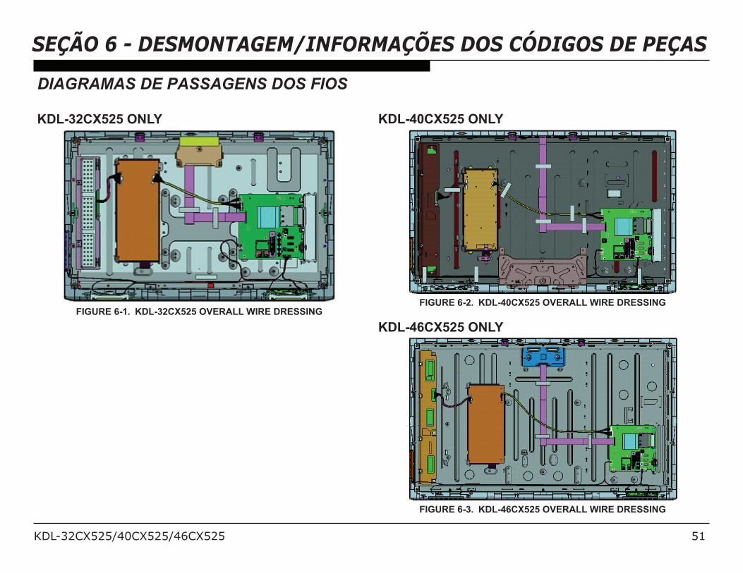
KDL-32CX525/40CX525/46CX525 51
SEÇÃO 6 - DESMONTAGEM/INFORMAÇÕES DOS CÓDIGOS DE PEÇAS
DIAGRAMAS DE PASSAGENS DOS FIOS
KDL-32CX525 ONLY
FIGURE 6-1. KDL-32CX525 OVERALL WIRE DRESSING
KDL-40CX525 ONLY
FIGURE 6-2. KDL-40CX525 OVERALL WIRE DRESSING
KDL-46CX525 ONLY
FIGURE 6-3. KDL-46CX525 OVERALL WIRE DRESSING
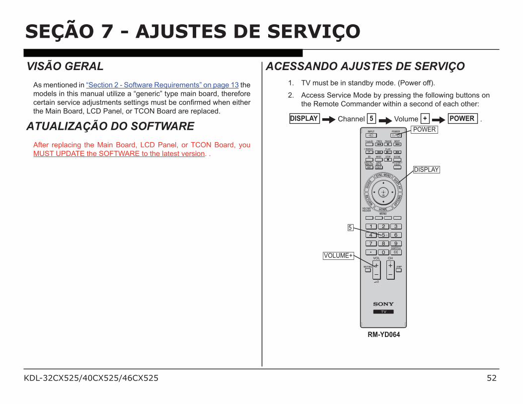
KDL-32CX525/40CX525/46CX525 52
VISÃO GERAL
As mentioned in “Section 2 - Software Requirements” on page 13 the
models in this manual utilize a “generic” type main board, therefore
!"#$%&'(!")% !'$*+,(#-!&#('(!##%&.('-,(#'/!' 0&1"-!*'23!&'!%#3!"'
the Main Board, LCD Panel, or TCON Board are replaced.
ATUALIZAÇÃO DO SOFTWARE
After replacing the Main Board, LCD Panel, or TCON Board, you
MUST UPDATE the SOFTWARE to the latest version. .
ACESSANDO AJUSTES DE SERVIÇO1. TV must be in standby mode. (Power off).
2. Access Service Mode by pressing the following buttons on
the Remote Commander within a second of each other:
DISPLAY Channel 5 Volume + POWER .
DISPLAY
RM-YD064
5
VOLUME+
POWER
SEÇÃO 7 - AJUSTES DE SERVIÇO
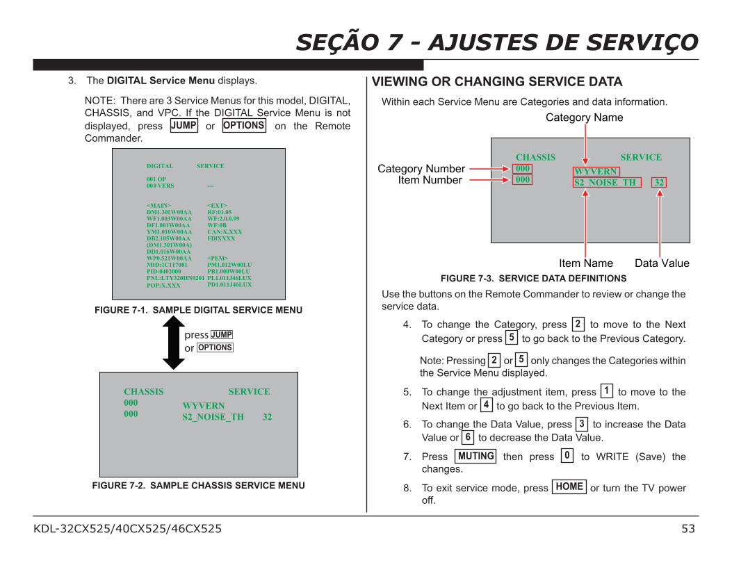
KDL-32CX525/40CX525/46CX525 53
SEÇÃO 7 - AJUSTES DE SERVIÇO3. The DIGITAL Service Menu displays.
NOTE: There are 3 Service Menus for this model, DIGITAL,
CHASSIS, and VPC. If the DIGITAL Service Menu is not
displayed, press JUMP or OPTIONS on the Remote
Commander.
DIGITAL SERVICE
001 OP000 VERS ---
<MAIN> <EXT>DM1.301W00AA RF:01.05WF1.003W00AA WF:2.0.0.99DF1.001W00AA WF:0BYM1.010W00AA CAN:X.XXXDB2.105W00AA FDlXXXX(DM1.301W00A)DD1.016W00AAWP0.521W00AA <PEM>MID:1C117081 PM1.012W00LUPID:0402000 PB1.000W00LUPNL:LTY320HN0201
POP:X.XXX
PL1.011J46LUXPD1.011J46LUX
FIGURE 7-1. SAMPLE DIGITAL SERVICE MENU
press
or
JUMP
OPTIONS
CHASSIS SERVICE
000
000 WYVERN
S2_NOISE_TH 32
FIGURE 7-2. SAMPLE CHASSIS SERVICE MENU
VIEWING OR CHANGING SERVICE DATA
Within each Service Menu are Categories and data information.
CHASSIS SERVICE
000
000 WYVERN
S2_NOISE_TH 32
Data ValueItem Name
Category NumberItem Number
Category Name
FIGURE 7-3. SERVICE DATA DEFINITIONS
Use the buttons on the Remote Commander to review or change the
service data.
4. To change the Category, press 2 to move to the Next
Category or press 5 to go back to the Previous Category.
Note: Pressing 2 or 5 only changes the Categories within
the Service Menu displayed.
5. To change the adjustment item, press 1 to move to the
Next Item or 4 to go back to the Previous Item.
6. To change the Data Value, press 3 to increase the Data
Value or 6 to decrease the Data Value.
7. Press MUTING then press 0 to WRITE (Save) the
changes.
8. To exit service mode, press HOME or turn the TV power
off.
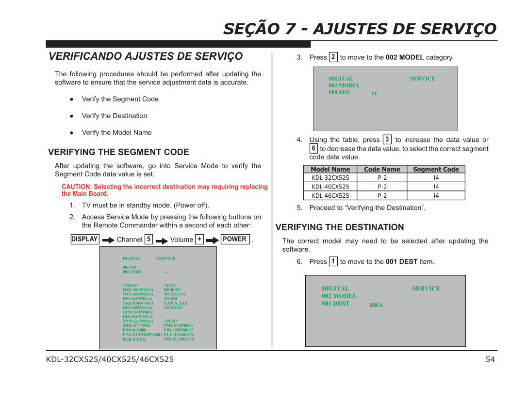
KDL-32CX525/40CX525/46CX525 54
SEÇÃO 7 - AJUSTES DE SERVIÇOVERIFICANDO AJUSTES DE SERVIÇO
The following procedures should be performed after updating the
software to ensure that the service adjustment data is accurate.
Verify the Segment Code
Verify the Destination
Verify the Model Name
VERIFYING THE SEGMENT CODE
After updating the software, go into Service Mode to verify the
Segment Code data value is set.
CAUTION: Selecting the incorrect destination may requiring replacing the Main Board.
1. TV must be in standby mode. (Power off).
2. Access Service Mode by pressing the following buttons on
the Remote Commander within a second of each other:
DISPLAY Channel 5 Volume + POWER .
DIGITAL SERVICE
001 OP000 VERS ---
<MAIN> <EXT>DM1.301W00AA RF:01.05WF1.003W00AA WF:2.0.0.99DF1.001W00AA WF:0BYM1.010W00AA CAN:X.XXXDB2.105W00AA FDlXXXX(DM1.301W00A)DD1.016W00AAWP0.521W00AA <PEM>MID:1C117081 PM1.012W00LUPID:0402000 PB1.000W00LUPNL:LTY320HN0201
POP:X.XXX
PL1.011J46LUXPD1.011J46LUX
3. Press 2 to move to the 002 MODEL category.
DIGITAL SERVICE
002 MODEL
000 SEG I4
4. Using the table, press 3 to increase the data value or
6 to decrease the data value, to select the correct segment
code data value.
Model Name Code Name Segment Code
!" #$%&'$' ( $ )*
!" *+%&'$' ( $ )*
!" *,%&'$' ( $ )*
5. Proceed to “Verifying the Destination”.
VERIFYING THE DESTINATION
The correct model may need to be selected after updating the
software.
6. Press 1 to move to the 001 DEST item.
DIGITAL SERVICE
002 MODEL
001 DEST BRA
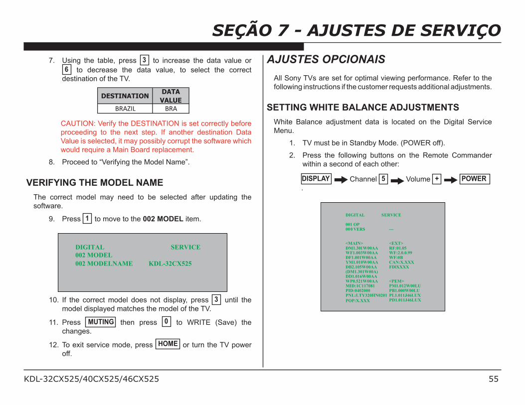
KDL-32CX525/40CX525/46CX525 55
SEÇÃO 7 - AJUSTES DE SERVIÇO7. Using the table, press 3 to increase the data value or
6 to decrease the data value, to select the correct
destination of the TV.
DESTINATIONDATA
VALUE
BRAZIL BRA
CAUTION: Verify the DESTINATION is set correctly before
proceeding to the next step. If another destination Data
Value is selected, it may possibly corrupt the software which
would require a Main Board replacement.
8. Proceed to “Verifying the Model Name”.
VERIFYING THE MODEL NAME
The correct model may need to be selected after updating the
software.
9. Press 1 to move to the 002 MODEL item.
DIGITAL SERVICE
002 MODEL
002 MODELNAME KDL-32CX525
10. If the correct model does not display, press 3 until the
model displayed matches the model of the TV.
11. Press MUTING then press 0 to WRITE (Save) the
changes.
12. To exit service mode, press HOME or turn the TV power
off.
AJUSTES OPCIONAIS
All Sony TVs are set for optimal viewing performance. Refer to the
following instructions if the customer requests additional adjustments.
SETTING WHITE BALANCE ADJUSTMENTS
White Balance adjustment data is located on the Digital Service
Menu.
1. TV must be in Standby Mode. (POWER off).
2. Press the following buttons on the Remote Commander
within a second of each other:
DISPLAY Channel 5 Volume + POWER
.
DIGITAL SERVICE
001 OP000 VERS ---
<MAIN> <EXT>DM1.301W00AA RF:01.05WF1.003W00AA WF:2.0.0.99DF1.001W00AA WF:0BYM1.010W00AA CAN:X.XXXDB2.105W00AA FDlXXXX(DM1.301W00A)DD1.016W00AAWP0.521W00AA <PEM>MID:1C117081 PM1.012W00LUPID:0402000 PB1.000W00LUPNL:LTY320HN0201
POP:X.XXX
PL1.011J46LUXPD1.011J46LUX
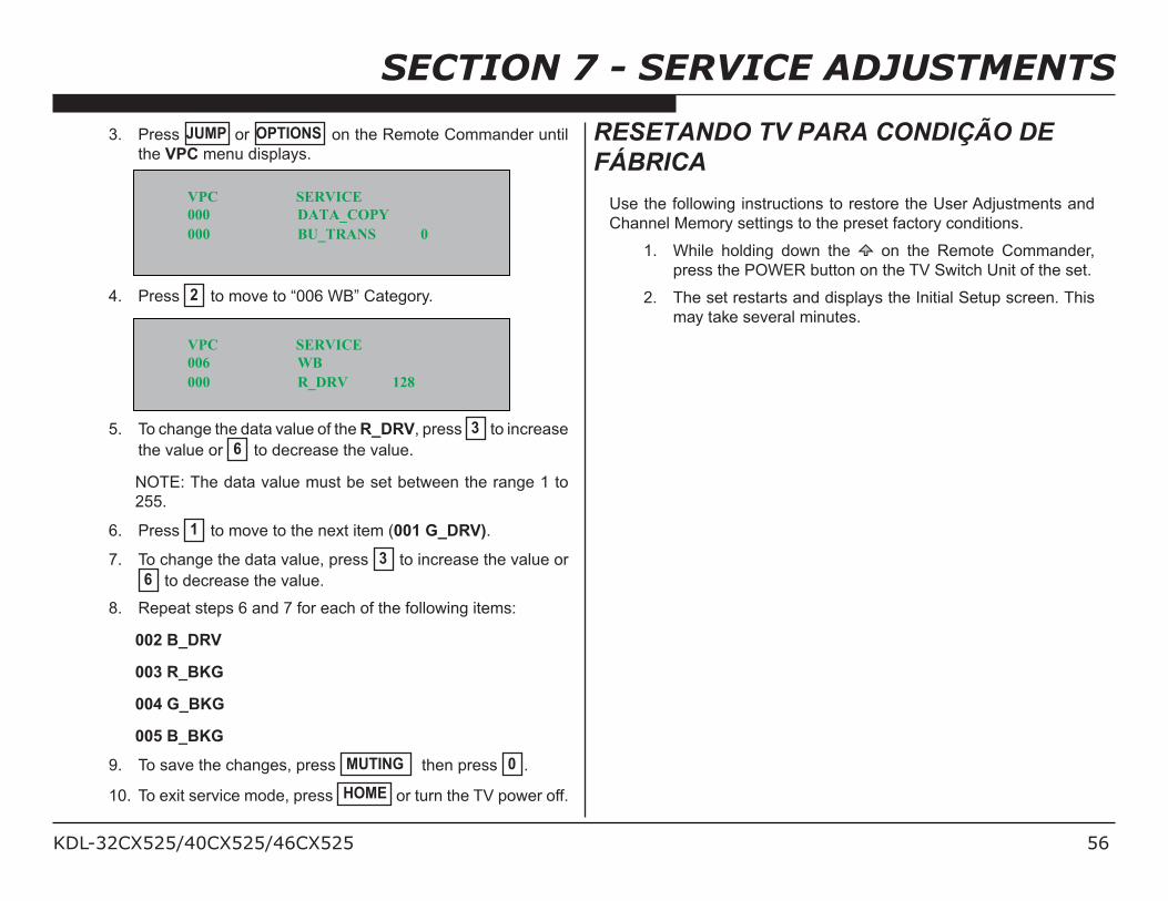
KDL-32CX525/40CX525/46CX525 56
SECTION 7 - SERVICE ADJUSTMENTS
3. Press JUMP or OPTIONS on the Remote Commander until
the VPC menu displays.
VPC SERVICE
000
000
DATA_COPY
BU_TRANS 0
4. Press 2 to move to “006 WB” Category.
VPC SERVICE
006
000
WB
R_DRV 128
5. To change the data value of the R_DRV, press 3 to increase
the value or 6 to decrease the value.
NOTE: The data value must be set between the range 1 to
255.
6. Press 1 to move to the next item (001 G_DRV).
7. To change the data value, press 3 to increase the value or
6 to decrease the value.
8. Repeat steps 6 and 7 for each of the following items:
002 B_DRV
003 R_BKG
004 G_BKG
005 B_BKG
9. To save the changes, press MUTING then press 0 .
10. To exit service mode, press HOME or turn the TV power off.
RESETANDO TV PARA CONDIÇÃO DEFÁBRICA
Use the following instructions to restore the User Adjustments and
Channel Memory settings to the preset factory conditions.
1. While holding down the on the Remote Commander,
press the POWER button on the TV Switch Unit of the set.
2. The set restarts and displays the Initial Setup screen. This
may take several minutes.
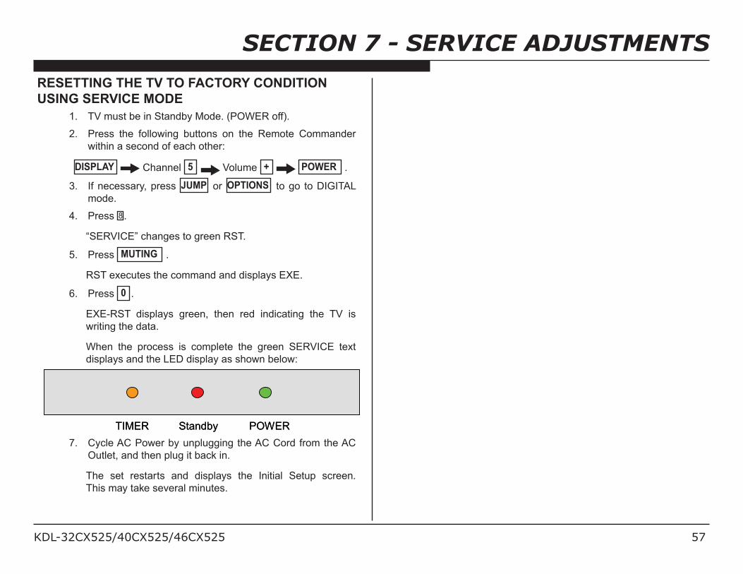
KDL-32CX525/40CX525/46CX525 57
SECTION 7 - SERVICE ADJUSTMENTS
RESETTING THE TV TO FACTORY CONDITION
USING SERVICE MODE
1. TV must be in Standby Mode. (POWER off).
2. Press the following buttons on the Remote Commander
within a second of each other:
DISPLAY Channel 5 Volume + POWER .
3. If necessary, press JUMP or OPTIONS to go to DIGITAL
mode.
4. Press 8 .
“SERVICE” changes to green RST.
5. Press MUTING .
RST executes the command and displays EXE.
6. Press 0 .
EXE-RST displays green, then red indicating the TV is
writing the data.
When the process is complete the green SERVICE text
displays and the LED display as shown below:
TIMER Standby POWERTIMER Standby POWER
7. Cycle AC Power by unplugging the AC Cord from the AC
Outlet, and then plug it back in.
The set restarts and displays the Initial Setup screen.
This may take several minutes.
KDL-32CX525/40CX525/46CX525 58
Sony CorporationSony Technology Center
Technical Services
Service Publications Department9-888-415-01
English
2011CJ74WEB-1
Printed in USA
© 2011.3
is a trademark of Sony Electronics
Reproduction in whole or part without written permission is prohibited. All rights reserved
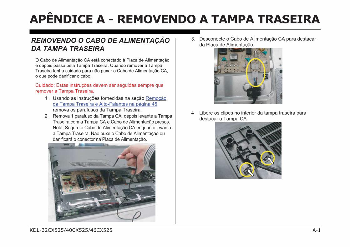
KDL-32CX525/40CX525/46CX525 A-1
APÊNDICE A - REMOVENDO A TAMPA TRASEIRA
REMOVENDO O CABO DE ALIMENTAÇÃODA TAMPA TRASEIRA
O Cabo de Alimentação CA está conectado à Placa de Alimentação
e depois passa pela Tampa Traseira. Quando remover a Tampa
Traseira tenha cuidado para não puxar o Cabo de Alimentação CA,
o que pode danificar o cabo.
Cuidado: Estas instruções devem ser seguidas sempre que
remover a Tampa Traseira.
1. Usando as instruções fornecidas na seção RemoçãoRemoção
da Tampa Traseira e Alto-Falantes na página 45
remova os parafusos da Tampa Traseira.
2. Remova 1 parafuso da Tampa CA, depois levante a Tampa
Traseira com a Tampa CA e Cabo de Alimentação presos.
Nota: Segure o Cabo de Alimentação CA enquanto levanta
a Tampa Traseira. Não puxe o Cabo de Alimentação ou
danificará o conector na Placa de Alimentação.
3. Desconecte o Cabo de Alimentação CA para destacar
da Placa de Alimentação.
4. Libere os clipes no interior da tampa traseira para
destacar a Tampa CA.