
Manutencao caixa direcao hilux.pdf
12
Gear Housing (4WD) REMOVAL AND INSTALLATION OF GEAR HOUSING Remove and install the parts as shown. – STEERING Power Steering (Gear Housing) SR–75
-
Upload
severinocv -
Category
Documents
-
view
228 -
download
0
Transcript of Manutencao caixa direcao hilux.pdf

8/12/2019 Manutencao caixa direcao hilux.pdf
http://slidepdf.com/reader/full/manutencao-caixa-direcao-hiluxpdf 1/12
Gear Housing (4WD)
REMOVAL AND INSTALLATION OF GEARHOUSING
Remove and install the parts as shown.
– STEERING Power Steering (Gear Housing)SR–75
8/12/2019 Manutencao caixa direcao hilux.pdf
http://slidepdf.com/reader/full/manutencao-caixa-direcao-hiluxpdf 2/12
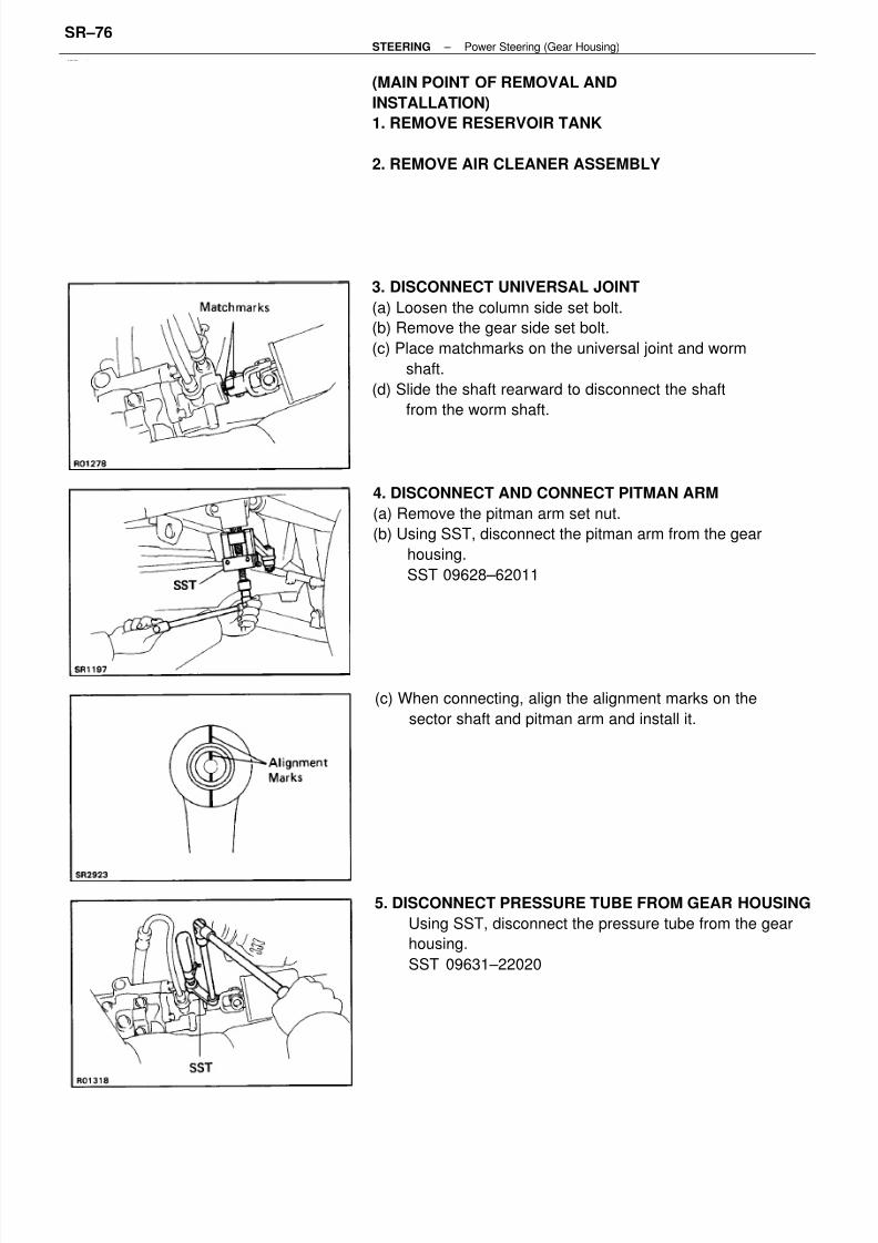
3. DISCONNECT UNIVERSAL JOINT
(a) Loosen the column side set bolt.
(b) Remove the gear side set bolt.
(c) Place matchmarks on the universal joint and worm
shaft.
(d) Slide the shaft rearward to disconnect the shaft
from the worm shaft.
4. DISCONNECT AND CONNECT PITMAN ARM
(a) Remove the pitman arm set nut.
(b) Using SST, disconnect the pitman arm from the gear
housing.
SST 09628–62011
5. DISCONNECT PRESSURE TUBE FROM GEAR HOUSING
Using SST, disconnect the pressure tube from the gear
housing.
SST 09631–22020
(MAIN POINT OF REMOVAL AND
INSTALLATION)
1. REMOVE RESERVOIR TANK
2. REMOVE AIR CLEANER ASSEMBLY
(c) When connecting, align the alignment marks on the
sector shaft and pitman arm and install it.
– STEERING Power Steering (Gear Housing)SR–76
8/12/2019 Manutencao caixa direcao hilux.pdf
http://slidepdf.com/reader/full/manutencao-caixa-direcao-hiluxpdf 3/12
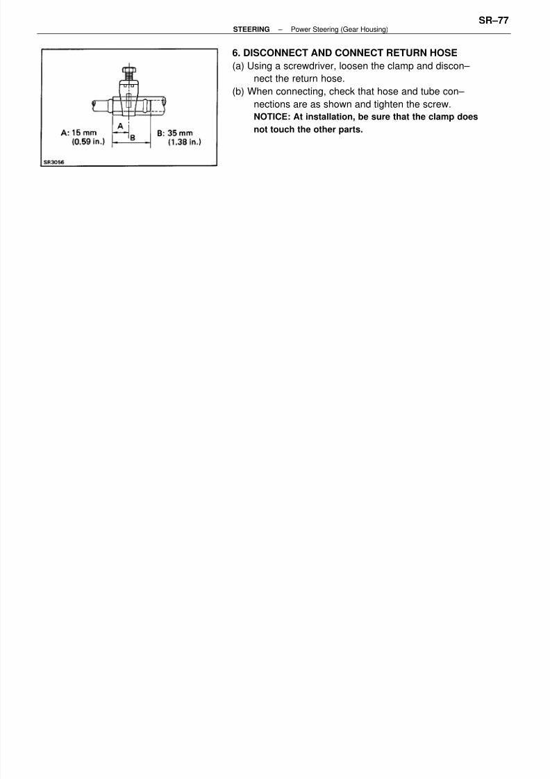
6. DISCONNECT AND CONNECT RETURN HOSE
(a) Using a screwdriver, loosen the clamp and discon–
nect the return hose.
(b) When connecting, check that hose and tube con–
nections are as shown and tighten the screw.
NOTICE: At installation, be sure that the clamp does
not touch the other parts.
– STEERING Power Steering (Gear Housing)SR–77

8/12/2019 Manutencao caixa direcao hilux.pdf
http://slidepdf.com/reader/full/manutencao-caixa-direcao-hiluxpdf 4/12
COMPONENTS
– STEERING Power Steering (Gear Housing)SR–78
8/12/2019 Manutencao caixa direcao hilux.pdf
http://slidepdf.com/reader/full/manutencao-caixa-direcao-hiluxpdf 5/12
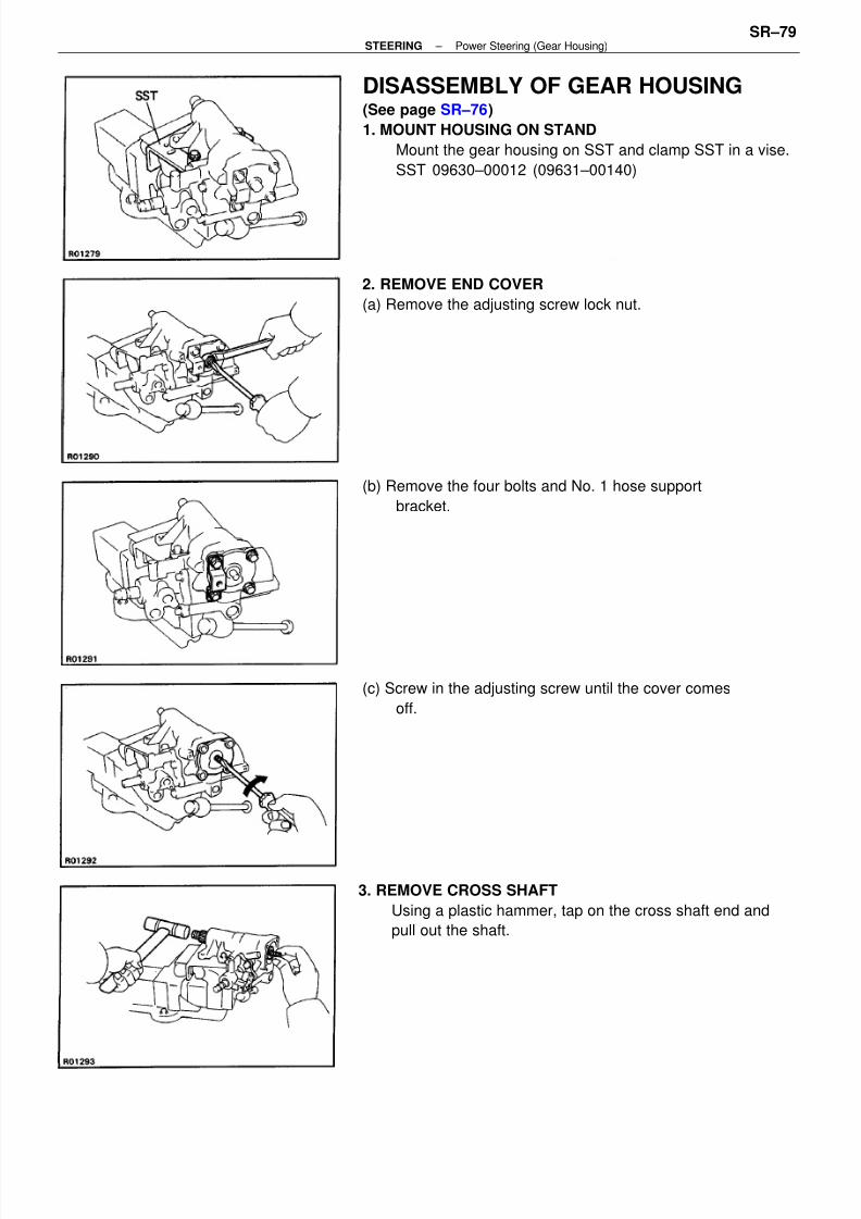
DISASSEMBLY OF GEAR HOUSING(See page SR–76)
1. MOUNT HOUSING ON STAND
Mount the gear housing on SST and clamp SST in a vise.
SST 09630–00012 (09631–00140)
3. REMOVE CROSS SHAFT
Using a plastic hammer, tap on the cross shaft end and
pull out the shaft.
(b) Remove the four bolts and No. 1 hose support
bracket.
(c) Screw in the adjusting screw until the cover comes
off.
2. REMOVE END COVER
(a) Remove the adjusting screw lock nut.
– STEERING Power Steering (Gear Housing)SR–79

8/12/2019 Manutencao caixa direcao hilux.pdf
http://slidepdf.com/reader/full/manutencao-caixa-direcao-hiluxpdf 6/12
(c) Hold the power piston nut with your thumb so it
cannot move, then withdraw the valve body and
power piston assembly.
NOTICE: Ensure that the power piston nut does not
come off the worm shaft.
(d) Remove the 0–ring.
4. REMOVE PLUNGER GUIDE NUT
(a) Using SST, remove the plunger guide nut.
SST 09043–38100
(b) Using SST, turn the shaft clockwise to disconnect
the worm gear valve body assembly from the gear
housing.
SST 09616–00010
5. REMOVE WORM GEAR VALVE BODY ASSEMBLY
(a) Remove the four cap bolts from the housing.
(b) Remove the spring, plunger and plunger guide nut.
(e) Remove the O–ring.
– STEERING Power Steering (Gear Housing)SR–80
8/12/2019 Manutencao caixa direcao hilux.pdf
http://slidepdf.com/reader/full/manutencao-caixa-direcao-hiluxpdf 7/12
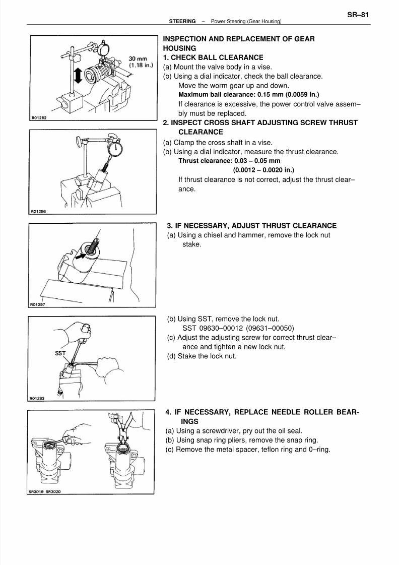
INSPECTION AND REPLACEMENT OF GEAR
HOUSING
1. CHECK BALL CLEARANCE
(a) Mount the valve body in a vise.
(b) Using a dial indicator, check the ball clearance.
Move the worm gear up and down.
Maximum ball clearance: 0.15 mm (0.0059 in.)
If clearance is excessive, the power control valve assem–
bly must be replaced.
2. INSPECT CROSS SHAFT ADJUSTING SCREW THRUST
CLEARANCE
(a) Clamp the cross shaft in a vise.
(b) Using a dial indicator, measure the thrust clearance.
Thrust clearance: 0.03 – 0.05 mm
(0.0012 – 0.0020 in.)
If thrust clearance is not correct, adjust the thrust clear–
ance.
(b) Using SST, remove the lock nut.
SST 09630–00012 (09631–00050)
(c) Adjust the adjusting screw for correct thrust clear–
ance and tighten a new lock nut.
(d) Stake the lock nut.
4. IF NECESSARY, REPLACE NEEDLE ROLLER BEAR-
INGS
(a) Using a screwdriver, pry out the oil seal.
(b) Using snap ring pliers, remove the snap ring.
(c) Remove the metal spacer, teflon ring and 0–ring.
3. IF NECESSARY, ADJUST THRUST CLEARANCE
(a) Using a chisel and hammer, remove the lock nut
stake.
– STEERING Power Steering (Gear Housing)SR–81
8/12/2019 Manutencao caixa direcao hilux.pdf
http://slidepdf.com/reader/full/manutencao-caixa-direcao-hiluxpdf 8/12
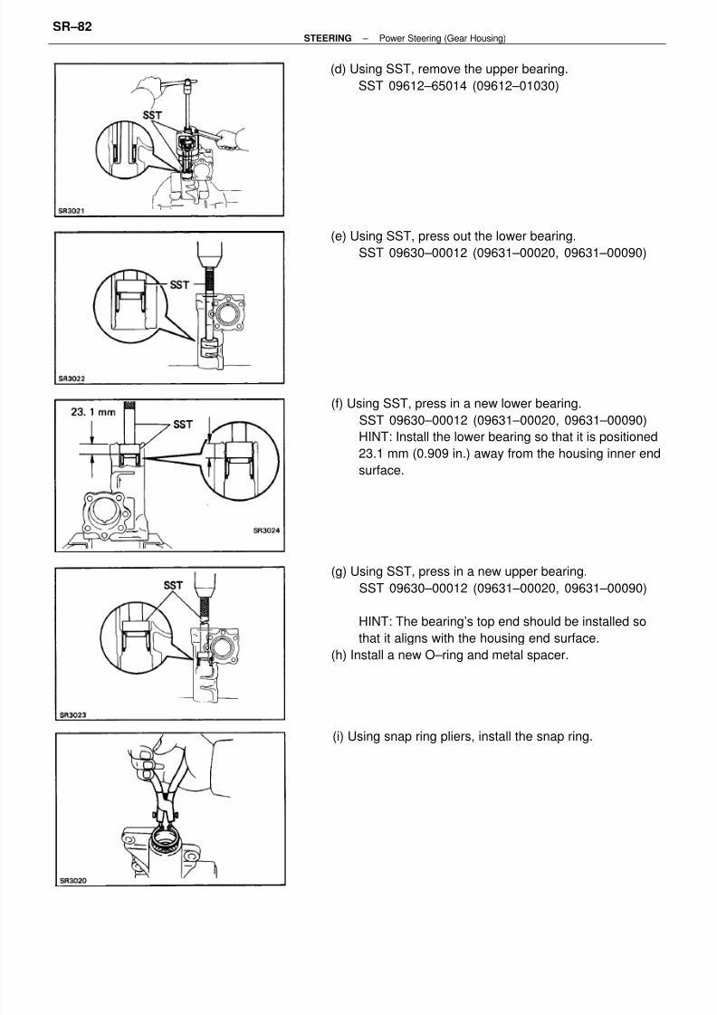
(g) Using SST, press in a new upper bearing.
SST 09630–00012 (09631–00020, 09631–00090)
HINT: The bearing’s top end should be installed so
that it aligns with the housing end surface.
(h) Install a new O–ring and metal spacer.
(f) Using SST, press in a new lower bearing.
SST 09630–00012 (09631–00020, 09631–00090)
HINT: Install the lower bearing so that it is positioned
23.1 mm (0.909 in.) away from the housing inner end
surface.
(e) Using SST, press out the lower bearing.
SST 09630–00012 (09631–00020, 09631–00090)
(d) Using SST, remove the upper bearing.
SST 09612–65014 (09612–01030)
(i) Using snap ring pliers, install the snap ring.
– STEERING Power Steering (Gear Housing)SR–82

8/12/2019 Manutencao caixa direcao hilux.pdf
http://slidepdf.com/reader/full/manutencao-caixa-direcao-hiluxpdf 9/12
5. IF NECESSARY, REPLACE CONTROL VALVE TEFLON
RING AND O–RING
(a) Using a screwdriver, remove the teflon ring and
0–ring.
NOTICE: Be careful not to damage the control valve.
(b) Install a new O–ring.
(c) Expand a new teflon ring with your fingers.
NOTICE: Be careful not to over–expand the teflon ring.
(d) Install the teflon ring.
(e) Coat the teflon ring with power steering fluid and
snug it down with piston ring compressor for 5 – 7
minutes.
(j) Form a new teflon ring into a heart shape and install
it with hand.
(k) Using SST, form the teflon ring.
NOTICE: The teflon ring must be squeezed before in–
serting the cross shaft or damage will result.
SST 09630–00012 (09631–00120)
(l) Using SST, drive a new oil seal into the gear hous–
ing.
SST 09630–00012 (09631–00020, 09631–00090)
6. IF NECESSARY, REPLACE UNION SEAT
(a) Using a screw extractor, remove the union seat.
– STEERING Power Steering (Gear Housing)SR–83

8/12/2019 Manutencao caixa direcao hilux.pdf
http://slidepdf.com/reader/full/manutencao-caixa-direcao-hiluxpdf 10/12
ASSEMBLY OF GEAR HOUSING
(See page SR–76)
1. INSTALL WORM GEAR VALVE BODY ASSEMBLY
(a) Install the three 0–rings to the gear housing and
valve body.
(b) Mount the gear housing on SST and clamp SST in
vise.
SST 09630–00012 (09631–00140)
(d) Using SST, check the worm gear preload.
SST 09616–00010
Preload (Starting): 0.3 – 0.5 N–m
(3 – 5.5 kgf –cm, 2.6 – 4.8 in. AM)
HINT: Hold the power piston nut to prevent it from turn–
ing.
If preload is not correct, replace the worm gear assembly.
2. INSTALL PLUNGER GUIDE NUT
(a) Install the plunger, plunger guide and spring.
(b) Install a new O–ring to the plunger guide nut and in–
stall the plunger guide nut with SST.
SST 09043–38100
Torque: 20 N–m (205 kgf–cm, 15 ft–lbf)
(c) Install and torque the four bolts.
Torque: 61 N–m (620 kgf–cm, 45 ft–lbf)
NOTICE: Be careful not to damage the teflon ring.
(b) Using a plastic hammer and extension bar, tap in a
new union seat.
– STEERING Power Steering (Gear Housing)SR–84

8/12/2019 Manutencao caixa direcao hilux.pdf
http://slidepdf.com/reader/full/manutencao-caixa-direcao-hiluxpdf 11/12
5. ADJUST CROSS SHAFT ADJUSTING SCREW
(a) Install SST with a torque meter on the worm shaft.
SST 09616–00010
(b) Turn the adjusting screw while measuring the pre–
load until it should be increased 0.2 – 0.4 N–m (2 –
4 kgf–cm, 1.7 – 3.5 in.–lbf) more than the preload
listed in step 1.
3. INSTALL CROSS SHAFT AND END COVER
(a) Install a new 0–ring on the end cover.
(b) Assemble the cross shaft to the end cover.
HINT: Fully loosen the adjusting screw.
(c) Set the worm gear at the center of the gear housing.
4. DETERMINE CENTER POSITION OF GEAR HOUSING
(a) Using SST, turn the worm shaft so full lock in both
directions and determine the exact center.
SST 09616–00010
(b) Place matchmarks on the worm shaft and housing
to show neutral position.
6. INSTALL NEW WASHER
7. INSTALL AND TIGHTEN LOCK NUT
Torque the lock nut while holding the adjusting screw.
Torque: 46 N–m (470 kgf–cm, 34 ft–lbf)
(d) Install and push the cross shaft into the gear hous–
ing so that the center teeth mesh together.
(e) Install the four cap bolts. Torque the bolts in a diag–
onal pattern.
Torque: 61 N–m (620 kgf–cm, 45 ft–lbf)
– STEERING Power Steering (Gear Housing)SR–85

8/12/2019 Manutencao caixa direcao hilux.pdf
http://slidepdf.com/reader/full/manutencao-caixa-direcao-hiluxpdf 12/12
8. CHECK TOTAL PRELOAD
Using SST with a torque meter, check total preload.
SST 09616–00010
Total preload (Starting):
0.5 – 0.9 N–m (5 – 9.5 kgf–cm, 4.3 – 8.3 in.–lbf)
– STEERING Power Steering (Gear Housing)SR–86