
Mise en page 1 - bautherm.ru fileFixing and actuation screws (x 4) Stop tap Flush plate housing...
15
SFA 153 07.08 IND1-01 NOTICE DE MONTAGE ET DE MAINTENANCE INSTALLATION AND MAINTENANCE INSTRUCTIONS MONTAGE- UND WARTUNGSANLEITUNG INSTRUCCIONES DE MONTAJE Y MANTENIMIENTO MONTAGE- EN ONDERHOUDSVOORSCHRIFTEN MANUAL DE MONTAGEM E MANUTENÇÃO SANI WALL ® Pro P E D UK F A lire attentivement et à conserver à titre d’information Please read carefully and retain for future reference Sorgfältig durchlesen und zur späteren Einsicht aufbewahren Leer atentamente y conservar a título informativo Aandachtig lezen en ter naslag bewaren A ler com atenção e a guardar a título de informação NL Notice SANIWALL PRO Traduction_1:Mise en page 1 23/09/2008 12:23 Page 1
-
Upload
phungduong -
Category
Documents
-
view
214 -
download
0
Transcript of Mise en page 1 - bautherm.ru fileFixing and actuation screws (x 4) Stop tap Flush plate housing...

SFA15307.08
IND1-01
NOTICE DE MONTAGE ET DE MAINTENANCEINSTALLATION AND MAINTENANCE INSTRUCTIONS
MONTAGE- UND WARTUNGSANLEITUNGINSTRUCCIONES DE MONTAJE Y MANTENIMIENTOMONTAGE- EN ONDERHOUDSVOORSCHRIFTEN
MANUAL DE MONTAGEM E MANUTENÇÃO
SANIWALL®
Pro
PEDUKF
A lire attentivement et à conserver à titre d’informationPlease read carefully and retain for future reference
Sorgfältig durchlesen und zur späteren Einsicht aufbewahrenLeer atentamente y conservar a título informativo
Aandachtig lezen en ter naslag bewarenA ler com atenção e a guardar a título de informação
NL
Notice SANIWALL PRO Traduction_1:Mise en page 1 23/09/2008 12:23 Page 1
de
f
g
h
i
kr
wx y
a
bc
v
u
t
za
zb
zb
zc
zc
zdze
zf
zg
zh
zi
zl
zm
zf1zf2
zf3
zj
s
z
j
lmnopq
1
zkzk
Notice SANIWALL PRO Traduction_1:Mise en page 1 23/09/2008 12:23 Page 2
3
Zf X1 X1 X1
X2X5
X1
X1
X22
Zk
Zc Zl
Zm
Zb Zj
ZdZe
X1 X1Zi
VI
65
Notice SANIWALL PRO Traduction_1:Mise en page 1 23/09/2008 12:24 Page 3
2
54
Ka
Kb
2
2
3
7.1.a
7.1.b 7.1.c
q
x
y
k
Notice SANIWALL PRO Traduction_1:Mise en page 1 23/09/2008 12:24 Page 4
1
2
v1
v2
7.2
7.3.a
3 4
Zc
Zb
Notice SANIWALL PRO Traduction_1:Mise en page 1 23/09/2008 12:24 Page 5
5
2
1
h
I
ˇ /ˇ
�/�0����d�������\
������������
2
V v1
7.3.b 7.4.a
7.4.b
c
e
1630
Notice SANIWALL PRO Traduction_1:Mise en page 1 23/09/2008 12:24 Page 6
h
Ij
B + 20mm
1 2
3
4
56
9
B
7
10
i ii iii iv
11
7.5
Notice SANIWALL PRO Traduction_1:Mise en page 1 23/09/2008 12:25 Page 7
ß
1 2 3
v1
4
6
1
2
3
4
c
c
c
7.6
11.a
11.b
5
Notice SANIWALL PRO Traduction_1:Mise en page 1 23/09/2008 12:25 Page 8
a
b
q
f
v
t
s
r
p
o
n
l
k
h
g
j
e
d
i
c
u
m
w
x
za
zk
zl
zm
zj
zi
zg
zf
zf1
zf2
zf3
zc
zb
ze
z
zd
y
zh
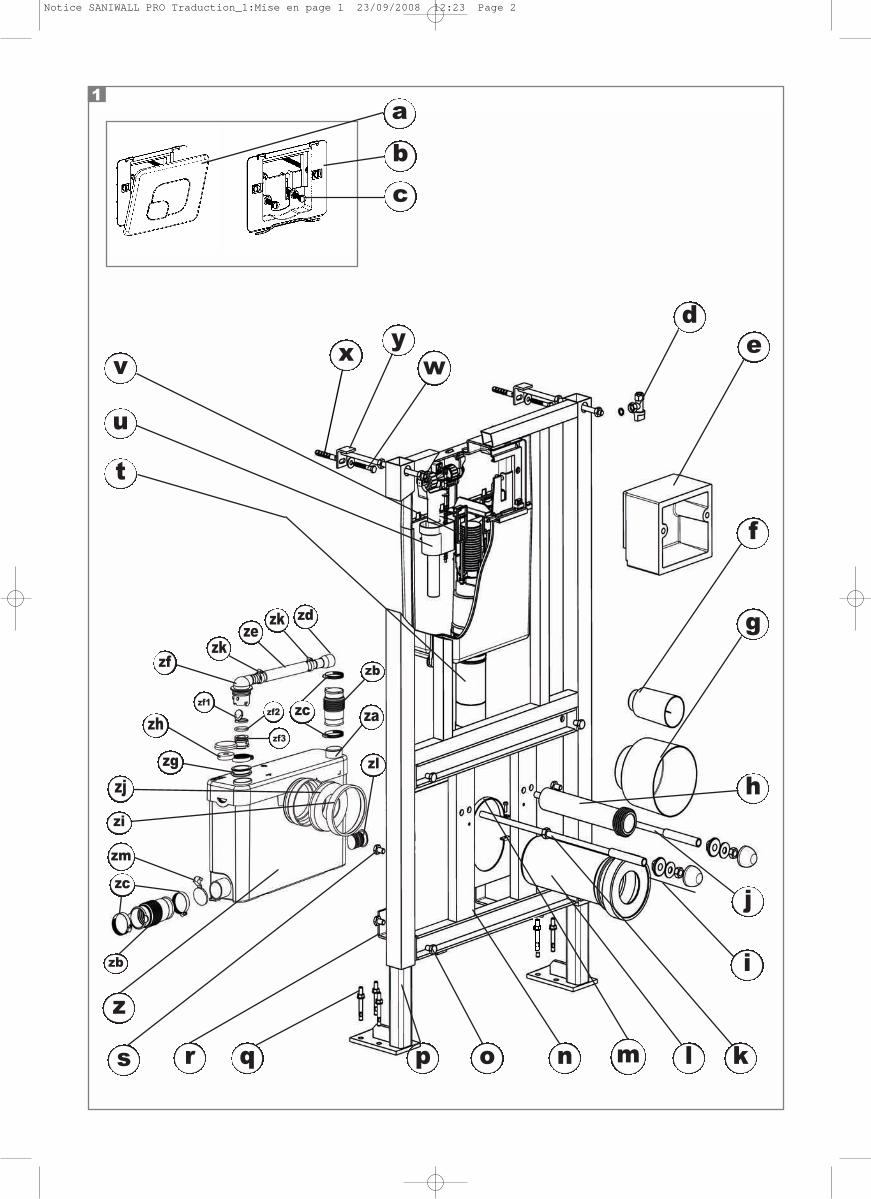
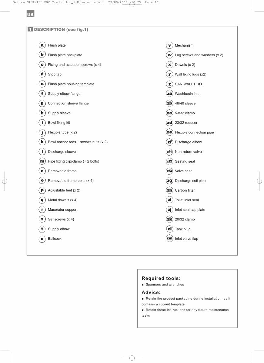
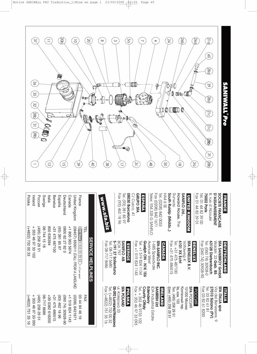
Flush plate
Flush plate backplate
Fixing and actuation screws (x 4)
Stop tap
Flush plate housing template
Supply elbow flange
Connection sleeve flange
Supply sleeve
Bowl fixing kit
Flexible tube (x 2)
Bowl anchor rods + screws nuts (x 2)
Discharge sleeve
Pipe fixing clip/clamp (+ 2 bolts)
Removable frame
Removable frame bolts (x 4)
Adjustable feet (x 2)
Metal dowels (x 4)
Macerator support
Set screws (x 4)
Supply elbow
Ballcock
Mechanism
Lag screws and washers (x 2)
Dowels (x 2)
Wall fixing lugs (x2)
SANIWALL PRO
Washbasin inlet
46/40 sleeve
53/32 clamp
23/32 reducer
Flexible connection pipe
Discharge elbow
Non-return valve
Seating seal
Valve seat
Discharge soil pipe
Carbon filter
Toilet inlet seal
Inlet seal cap plate
20/32 clamp
Tank plug
Inlet valve flap
Required tools: ■ Spanners and wrenches
Advice:■ Retain the product packaging during installation, as it
contains a cut-out template
■ Retain these instructions for any future maintenance
tasks
DESCRIPTION (see fig.1)1
UK
Notice SANIWALL PRO Traduction_1:Mise en page 1 23/09/2008 12:25 Page 15
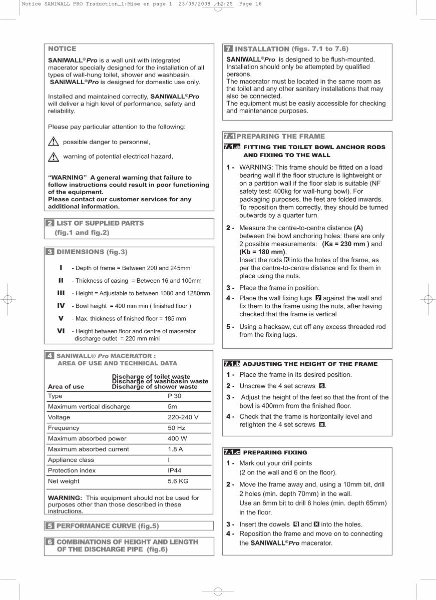
NOTICESANIWALL®Pro is a wall unit with integratedmacerator specially designed for the installation of alltypes of wall-hung toilet, shower and washbasin.SANIWALL®Pro is designed for domestic use only.
Installed and maintained correctly, SANIWALL®Prowill deliver a high level of performance, safety andreliability.
Please pay particular attention to the following:
possible danger to personnel,
warning of potential electrical hazard,
“WARNING” A general warning that failure tofollow instructions could result in poor functioningof the equipment.Please contact our customer services for anyadditional information.
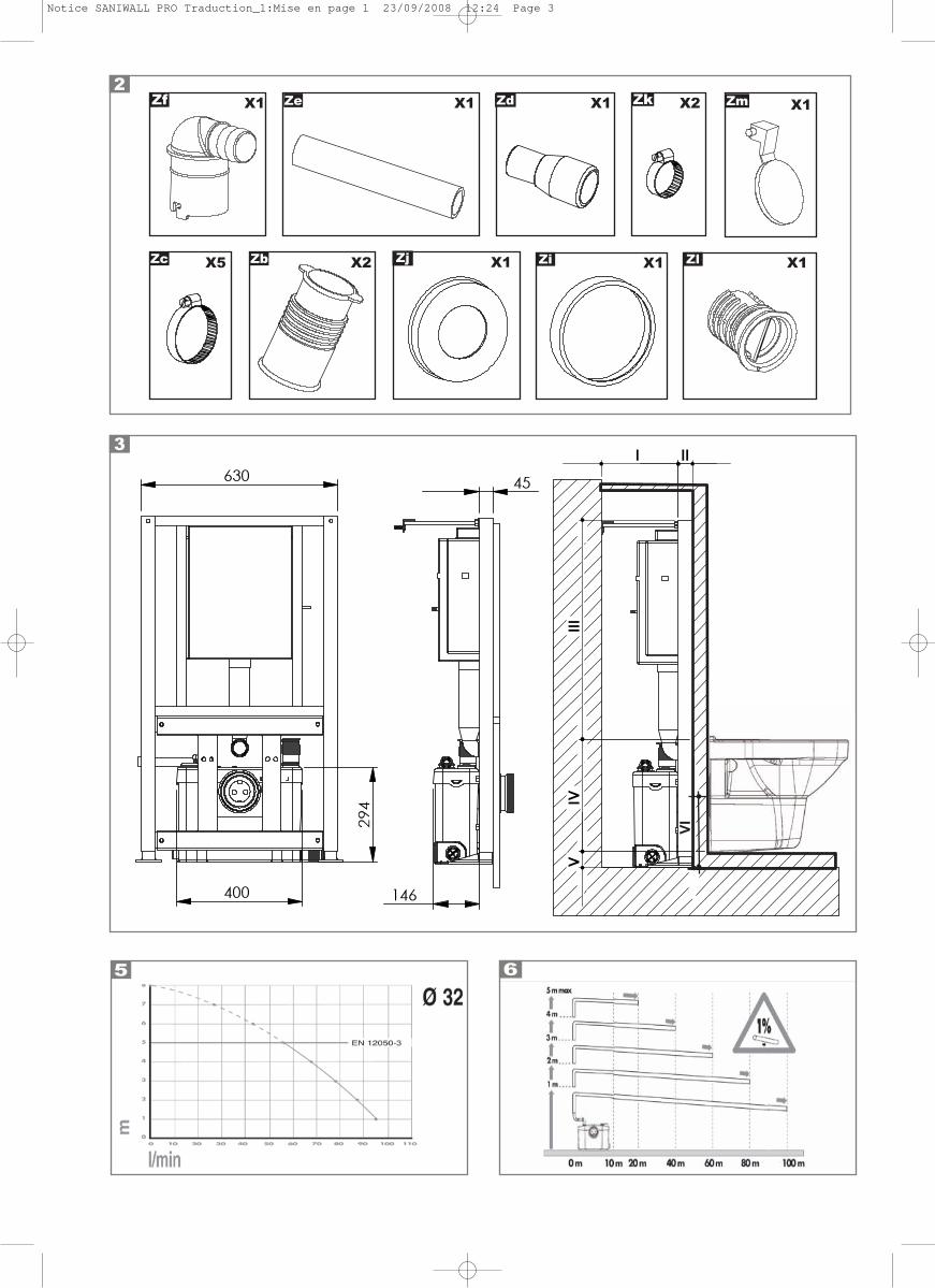
LIST OF SUPPLIED PARTS(fig.1 and fig.2)
2
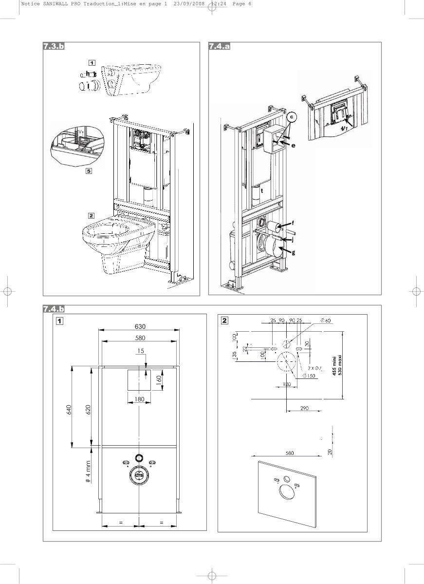
DIMENSIONS (fig.3)
- Depth of frame = Between 200 and 245mm
- Thickness of casing = Between 16 and 100mm
- Height = Adjustable to between 1080 and 1280mm
- Bowl height = 400 mm min ( finished floor )
- Max. thickness of finished floor = 185 mm
- Height between floor and centre of maceratordischarge outlet = 220 mm mini
3
PERFORMANCE CURVE (fig.5)5
COMBINATIONS OF HEIGHT AND LENGTH OF THE DISCHARGE PIPE (fig.6)
6
INSTALLATION (figs. 7.1 to 7.6)SANIWALL®Pro is designed to be flush-mounted.Installation should only be attempted by qualifiedpersons.The macerator must be located in the same room asthe toilet and any other sanitary installations that mayalso be connected.The equipment must be easily accessible for checkingand maintenance purposes.
7
SANIWALL® Pro MACERATOR : AREA OF USE AND TECHNICAL DATA
Discharge of toilet wasteArea of use
Discharge of washbasin wasteDischarge of shower waste
Type P 30
Maximum vertical discharge 5m
Voltage 220-240 V
Frequency 50 Hz
Maximum absorbed power 400 W
Maximum absorbed current 1.8 A
Appliance class I
Protection index IP44
Net weight 5.6 KG
WARNING: This equipment should not be used forpurposes other than those described in theseinstructions.
4
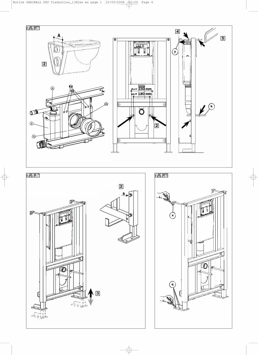
PREPARING THE FRAMEFITTING THE TOILET BOWL ANCHOR RODSAND FIXING TO THE WALL
1 - WARNING: This frame should be fitted on a load bearing wall if the floor structure is lightweight or on a partition wall if the floor slab is suitable (NF safety test: 400kg for wall-hung bowl). For packaging purposes, the feet are folded inwards.To reposition them correctly, they should be turnedoutwards by a quarter turn.
2 - Measure the centre-to-centre distance (A)between the bowl anchoring holes: there are only 2 possible measurements: (Ka = 230 mm ) and (Kb = 180 mm).Insert the rods into the holes of the frame, as per the centre-to-centre distance and fix them in place using the nuts.
3 - Place the frame in position.4 - Place the wall fixing lugs against the wall and
fix them to the frame using the nuts, after having checked that the frame is vertical
5 - Using a hacksaw, cut off any excess threaded rod from the fixing lugs.
K
y
7.17.1.a
ADJUSTING THE HEIGHT OF THE FRAME
1 - Place the frame in its desired position.
2 - Unscrew the 4 set screws .
3 - Adjust the height of the feet so that the front of thebowl is 400mm from the finished floor.
4 - Check that the frame is horizontally level and retighten the 4 set screws .
s
s
PREPARING FIXING
1 - Mark out your drill points (2 on the wall and 6 on the floor).
2 - Move the frame away and, using a 10mm bit, drill 2 holes (min. depth 70mm) in the wall.Use an 8mm bit to drill 6 holes (min. depth 65mm)in the floor.
3 - Insert the dowels and into the holes.4 - Reposition the frame and move on to connecting
the SANIWALL®Pro macerator.
xq
7.1.b
7.1.c
I
II
III
IV
V
VI
Notice SANIWALL PRO Traduction_1:Mise en page 1 23/09/2008 12:25 Page 16
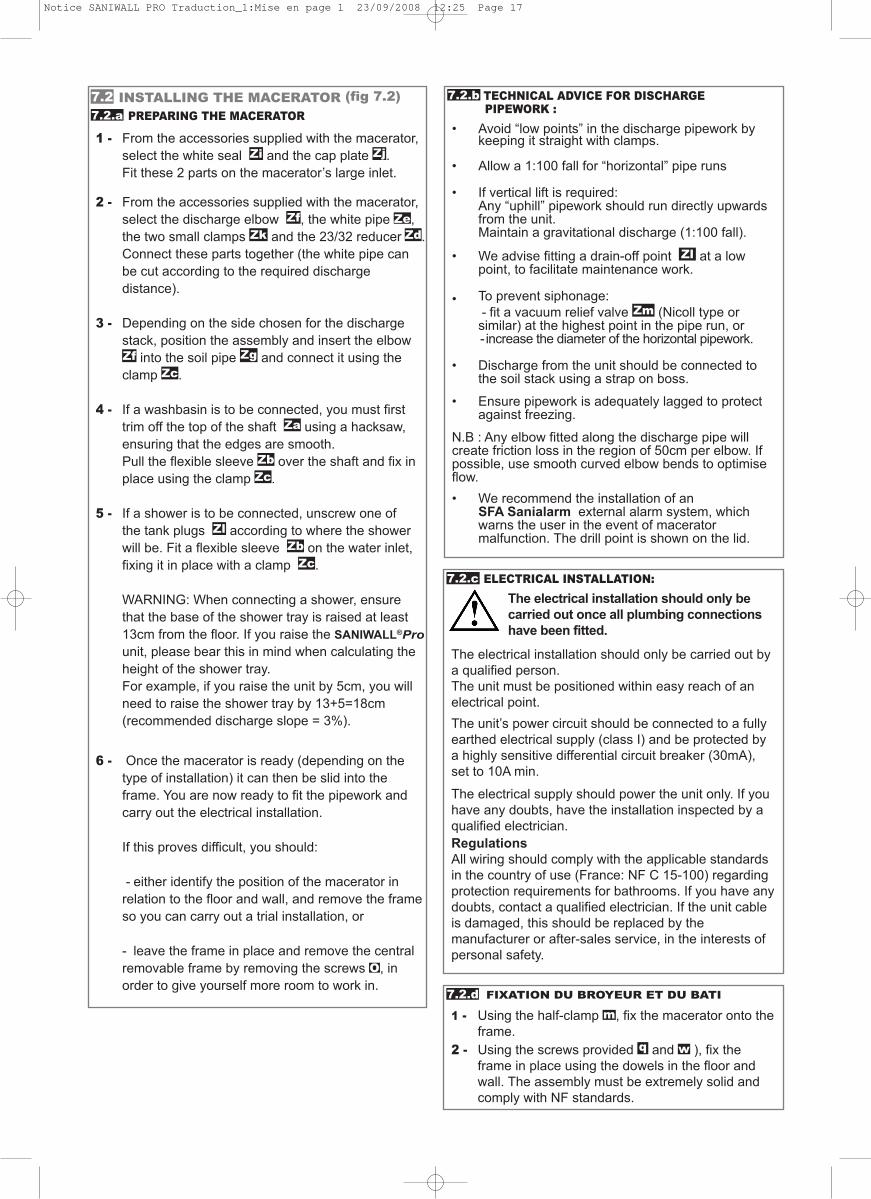
TECHNICAL ADVICE FOR DISCHARGE PIPEWORK :
• Avoid “low points” in the discharge pipework by keeping it straight with clamps.
• Allow a 1:100 fall for “horizontal” pipe runs
• If vertical lift is required:Any “uphill” pipework should run directly upwards from the unit.Maintain a gravitational discharge (1:100 fall).
• We advise fitting a drain-off point at a low point, to facilitate maintenance work.
• To prevent siphonage:- fit a vacuum relief valve (Nicoll type or similar) at the highest point in the pipe run, or - increase the diameter of the horizontal pipework.
• Discharge from the unit should be connected to the soil stack using a strap on boss.
• Ensure pipework is adequately lagged to protect against freezing.
N.B : Any elbow fitted along the discharge pipe willcreate friction loss in the region of 50cm per elbow. Ifpossible, use smooth curved elbow bends to optimiseflow.• We recommend the installation of an
SFA Sanialarm external alarm system, which warns the user in the event of macerator malfunction. The drill point is shown on the lid.
Zm
Zl
FIXATION DU BROYEUR ET DU BATI
1 - Using the half-clamp , fix the macerator onto theframe.
2 - Using the screws provided and ), fix the frame in place using the dowels in the floor and wall. The assembly must be extremely solid and comply with NF standards.
wq
m
ELECTRICAL INSTALLATION:The electrical installation should only becarried out once all plumbing connectionshave been fitted.
The electrical installation should only be carried out bya qualified person.The unit must be positioned within easy reach of anelectrical point.The unit’s power circuit should be connected to a fullyearthed electrical supply (class I) and be protected bya highly sensitive differential circuit breaker (30mA),set to 10A min.
The electrical supply should power the unit only. If youhave any doubts, have the installation inspected by aqualified electrician.Regulations All wiring should comply with the applicable standardsin the country of use (France: NF C 15-100) regardingprotection requirements for bathrooms. If you have anydoubts, contact a qualified electrician. If the unit cableis damaged, this should be replaced by themanufacturer or after-sales service, in the interests ofpersonal safety.
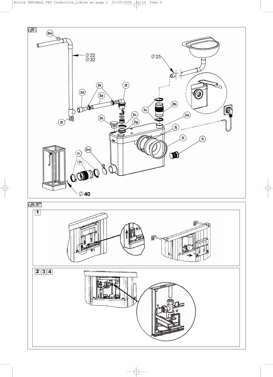
INSTALLING THE MACERATOR (fig 7.2)PREPARING THE MACERATOR
1 - From the accessories supplied with the macerator, select the white seal and the cap plate . Fit these 2 parts on the macerator’s large inlet.
2 - From the accessories supplied with the macerator, select the discharge elbow , the white pipe ,the two small clamps and the 23/32 reducer .Connect these parts together (the white pipe can be cut according to the required discharge distance).
3 - Depending on the side chosen for the discharge stack, position the assembly and insert the elbow
into the soil pipe and connect it using the clamp .
4 - If a washbasin is to be connected, you must first trim off the top of the shaft using a hacksaw, ensuring that the edges are smooth.Pull the flexible sleeve over the shaft and fix in place using the clamp .
5 - If a shower is to be connected, unscrew one of the tank plugs according to where the shower will be. Fit a flexible sleeve on the water inlet, fixing it in place with a clamp .
WARNING: When connecting a shower, ensure that the base of the shower tray is raised at least 13cm from the floor. If you raise the SANIWALL®Prounit, please bear this in mind when calculating the height of the shower tray.For example, if you raise the unit by 5cm, you will need to raise the shower tray by 13+5=18cm (recommended discharge slope = 3%).
6 - Once the macerator is ready (depending on the type of installation) it can then be slid into the frame. You are now ready to fit the pipework and carry out the electrical installation.
If this proves difficult, you should:
- either identify the position of the macerator in relation to the floor and wall, and remove the frameso you can carry out a trial installation, or
- leave the frame in place and remove the central removable frame by removing the screws , in order to give yourself more room to work in.
Zk Zd
ZlZb
Zb
Zc
Za
Zc
ZcZgZf
ZeZf
Zj
O
Zi
7.27.2.a
7.2.b
7.2.c
7.2.d
Notice SANIWALL PRO Traduction_1:Mise en page 1 23/09/2008 12:25 Page 17
7.4
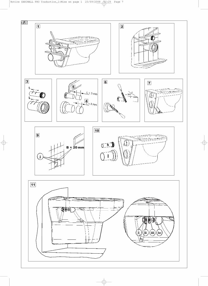
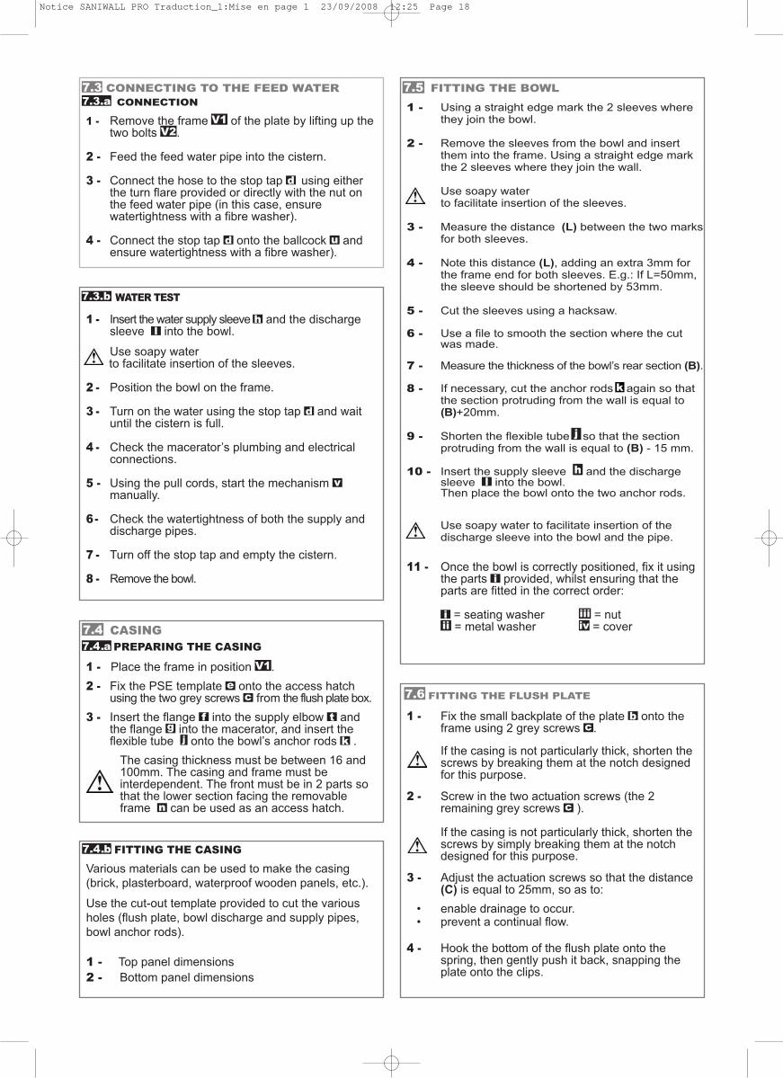
FITTING THE BOWL
1 - Using a straight edge mark the 2 sleeves where they join the bowl.
2 - Remove the sleeves from the bowl and insert them into the frame. Using a straight edge mark the 2 sleeves where they join the wall.
Use soapy water to facilitate insertion of the sleeves.
3 - Measure the distance (L) between the two marksfor both sleeves.
4 - Note this distance (L), adding an extra 3mm for the frame end for both sleeves. E.g.: If L=50mm, the sleeve should be shortened by 53mm.
5 - Cut the sleeves using a hacksaw.
6 - Use a file to smooth the section where the cut was made.
7 - Measure the thickness of the bowl’s rear section (B).
8 - If necessary, cut the anchor rods again so that the section protruding from the wall is equal to (B)+20mm.
9 - Shorten the flexible tube so that the section protruding from the wall is equal to (B) - 15 mm.
10 - Insert the supply sleeve and the discharge sleeve into the bowl. Then place the bowl onto the two anchor rods.
Use soapy water to facilitate insertion of the discharge sleeve into the bowl and the pipe.
11 - Once the bowl is correctly positioned, fix it using the parts provided, whilst ensuring that the parts are fitted in the correct order:
= seating washer = nut= metal washer = cover
i
iviii
iii
lh
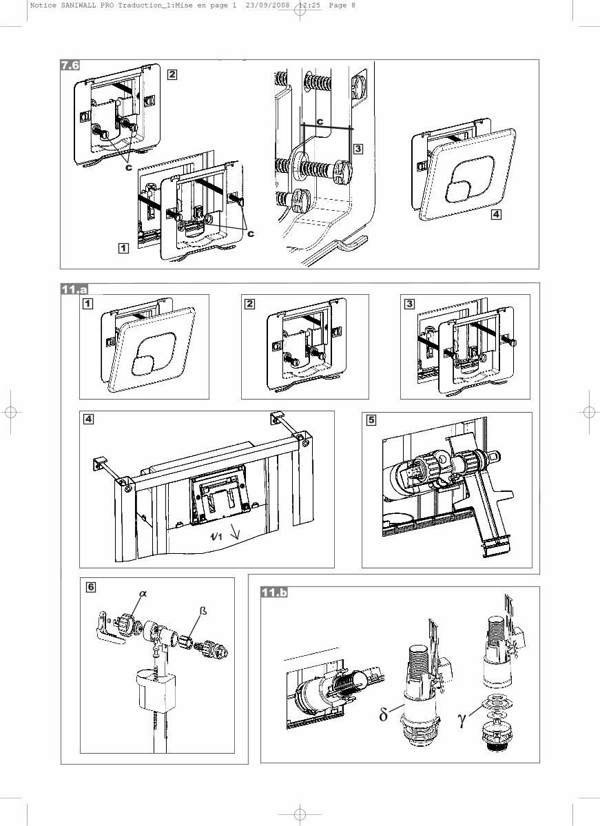
FITTING THE FLUSH PLATE
1 - Fix the small backplate of the plate onto the frame using 2 grey screws .
If the casing is not particularly thick, shorten the screws by breaking them at the notch designed for this purpose.
2 - Screw in the two actuation screws (the 2 remaining grey screws ).
If the casing is not particularly thick, shorten the screws by simply breaking them at the notch designed for this purpose.
3 - Adjust the actuation screws so that the distance(C) is equal to 25mm, so as to:
• enable drainage to occur.• prevent a continual flow.
4 - Hook the bottom of the flush plate onto the spring, then gently push it back, snapping the plate onto the clips.
c
bc
7.6
I FITTING THE CASING
Various materials can be used to make the casing(brick, plasterboard, waterproof wooden panels, etc.).
Use the cut-out template provided to cut the variousholes (flush plate, bowl discharge and supply pipes,bowl anchor rods).
1 - Top panel dimensions2 - Bottom panel dimensions
7.4.a
7.4.b
7.5
CASINGPREPARING THE CASING
1 - Place the frame in position .2 - Fix the PSE template onto the access hatch
using the two grey screws from the flush plate box.3 - Insert the flange into the supply elbow and
the flange into the macerator, and insert the flexible tube onto the bowl’s anchor rods .
The casing thickness must be between 16 and 100mm. The casing and frame must be interdependent. The front must be in 2 parts so that the lower section facing the removable frame can be used as an access hatch.
k
n
jg
tf
ce
V1
j
WATER TEST
1 - Insert the water supply sleeve and the discharge sleeve into the bowl.
Use soapy waterto facilitate insertion of the sleeves.
2 - Position the bowl on the frame.
3 - Turn on the water using the stop tap and wait until the cistern is full.
4 - Check the macerator’s plumbing and electrical connections.
5 - Using the pull cords, start the mechanism manually.
6 - Check the watertightness of both the supply and discharge pipes.
7 - Turn off the stop tap and empty the cistern.
8 - Remove the bowl.
v
d
lh
7.3.b
CONNECTING TO THE FEED WATERCONNECTION
1 - Remove the frame of the plate by lifting up thetwo bolts .
2 - Feed the feed water pipe into the cistern.
3 - Connect the hose to the stop tap using either the turn flare provided or directly with the nut on the feed water pipe (in this case, ensure watertightness with a fibre washer).
4 - Connect the stop tap onto the ballcock and ensure watertightness with a fibre washer).
ud
d
V2V1
7.37.3.a
k
Notice SANIWALL PRO Traduction_1:Mise en page 1 23/09/2008 12:25 Page 18
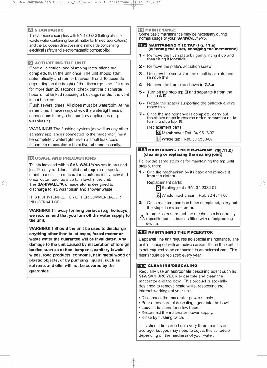
11
MAINTAINING THE MECHANISM (fig.11.b)(cleaning or replacing the sealing joint)
Follow the same steps as for maintaining the tap untilstep 6, then:1 - Grip the mechanism by its base and remove it
from the cistern.Replacement parts:
Sealing joint : Réf. 34 2332-07
Whole mechanism : Réf. 32 4544-07
2 - Once maintenance has been completed, carry outthe steps in reverse order. In order to ensure that the mechanism is correctlyrepositioned, its base is fitted with a foolproofing device.
MAINTAINING THE MACERATOR
L’appareil The unit requires no special maintenance. Theunit is equipped with an active carbon filter in the vent. Itis not required to be connected to an external vent. Thisfilter should be replaced every year.
CLEANING/DESCALINGRegularly use an appropriate descaling agent such asSFA SANIBROYEUR to descale and clean themacerator and the bowl. This product is speciallydesigned to remove scale whilst respecting theinternal workings of your unit.
• Disconnect the macerator power supply.• Pour a measure of descaling agent into the bowl.• Leave it to stand for a few hours.• Reconnect the macerator power supply.• Rinse by flushing twice.
This should be carried out every three months onaverage, but you may need to adjust this scheduledepending on the hardness of your water.
MAINTENANCESome basic maintenance may be necessary duringnormal usage of your SANIWALL®Pro.
MAINTAINING THE TAP (fig. 11.a)(cleaning the filter, changing the membrane)
1 - Remove the flush plate by gently lifting it up and then tilting it forwards.
2 - Remove the plate’s actuation screw.
3 - Unscrew the screws on the small backplate and remove this.
4 - Remove the frame as shown in 7.3.a.
5 - Turn off the stop tap and separate it from the ballcock .
6 - Rotate the spacer supporting the ballcock and remove this.
7 - Once the maintenance is complete, carry out the above steps in reverse order, remembering to turn the stop tap .Replacement parts:
Membrane : Réf. 34 9513-07Whole tap : Réf. 30 9503-07
ud
d
11.a
11.b
11.c
11.d
USAGE AND PRECAUTIONSToilets installed with a SANIWALL®Pro are to be usedjust like any traditional toilet and require no specialmaintenance. The macerator is automatically activatedonce water reaches a certain level in the unit. The SANIWALL®Pro macerator is designed todischarge toilet, washbasin and shower waste.
IT IS NOT INTENDED FOR EITHER COMMERCIAL ORINDUSTRIAL USE.
WARNING!!! If away for long periods (e.g. holidays),we recommend that you turn off the water supply tothe unit.
WARNING!!! Should the unit be used to dischargeanything other than toilet paper, faecal matter orwaste water the guarantee will be invalidated. Anydamage to the unit caused by maceration of foreignbodies such as cotton, tampons, sanitary towels,wipes, food products, condoms, hair, metal wood orplastic objects, or by pumping liquids, such assolvents and oils, will not be covered by theguarantee.
10
ACTIVATING THE UNITOnce all electrical and plumbing installations arecomplete, flush the unit once. The unit should startautomatically and run for between 5 and 10 secondsdepending on the height of the discharge pipe. If it runsfor more than 20 seconds, check that the dischargehose is not kinked (causing a blockage) or that the ventis not blocked.Flush several times. All pipes must be watertight. At thesame time, if necessary, check the watertightness ofconnections to any other sanitary appliances (e.g.washbasin).
WARNING!!! The flushing system (as well as any othersanitary appliances connected to the macerator) mustbe completely watertight. Even a small leak couldcause the macerator to be activated unnecessarily.
9
STANDARDSThis appliance complies with EN 12050-3 (Lifting plant forwaste water containing faecal matter for limited applications)and the European directives and standards concerningelectrical safety and electromagnetic compatibility.
8
Notice SANIWALL PRO Traduction_1:Mise en page 1 23/09/2008 12:25 Page 19
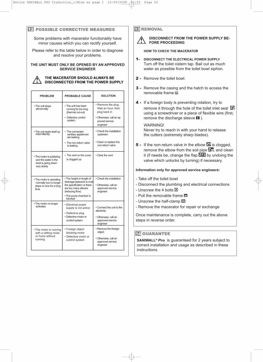
GUARANTEESANIWALL®Pro is guaranteed for 2 years subject tocorrect installation and usage as described in theseinstructions.
14
13 REMOVAL
DISCONNECT FROM THE POWER SUPPLY BE-FORE PROCEEDING
HOW TO CHECK THE MACERATOR
1- DISCONNECT THE ELECTRICAL POWER SUPPLYTurn off the toilet cistern tap. Bail out as much water as possible from the toilet bowl siphon.
2 - Remove the toilet bowl.
3 - Remove the casing and the hatch to access the removable frame .
4 - If a foreign body is preventing rotation, try to remove it through the hole of the toilet inlet seal using a screwdriver or a piece of flexible wire (first, remove the discharge sleeve ).
WARNING!Never try to reach in with your hand to releasethe cutters (extremely sharp blades).
5 - If the non-return valve in the elbow is clogged, remove the elbow from the soil pipe , and clean it (if needs be, change the flap by undoing the valve which unlocks by turning) if necessary.
Information only for approved service engineers:
- Take off the toilet bowl- Disconnect the plumbing and electrical connections- Unscrew the 4 bolts - Pull the removable frame - Unscrew the half-clamp - Remove the macerator for repair or exchange
Once maintenance is complete, carry out the abovesteps in reverse order.
mn
O
Zf3ZgZf
l
Zj
nPROBLEM
• The unit stops abnormally
• The unit starts itself upintermittently
• The motor is juddering and the water in the bowl is going downvery slowly
• The motor is operating normally but no longerstops or runs for a long time
• The motor no longer activates
• The motor is runningwith a rattling noise or hums without running
PROBABLE CAUSE
• The unit has been running for too long (thermal cut-out)
• Defective controlsystem
• The connectedsanitary appliances are leaking
• The non-return valveis leaking
• The vent on the cover is clogged up
• The height or length ofdrainage pipework is overthe specification or thereare too many elbows(reducing flow)• The pump chamber is
blocked
• Electrical power supply is not active
• Defective plug• Defective motor or
control system
• Foreign object blocking motor
• Defective motor or control system
SOLUTION
• Remove the plug. Wait an hour, thenplug back in
• Otherwise, call an approved service engineer
• Check the installation upstream
• Clean or replace the non-return valve
• Clear the vent
• Check the installation
• Otherwise, call an approved service engineer
• Connect the unit to theelectricity
• Otherwise, call an approved service engineer
• Remove the foreign object
• Otherwise, call an approved service engineer
POSSIBLE CORRECTIVE MEASURES
Some problems with macerator functionality haveminor causes which you can rectify yourself.
Please refer to the table below in order to diagnoseand resolve your problems.
THE UNIT MUST ONLY BE OPENED BY AN APPROVEDSERVICE ENGINEER
THE MACERATOR SHOULD ALWAYS BEDISCONNECTED FROM THE POWER SUPPLY
12
Notice SANIWALL PRO Traduction_1:Mise en page 1 23/09/2008 12:25 Page 20
SANIW
ALL
®Pro
SA
NIC
OM
PA
CT
®
C4
, C4
3, C
48
, LU
XE
, PR
O, E
LIT
E
© SFA - D 6637 Graphic Plus +33/1/5399 9292. Photo Voncken - Printed in CEE. SOUS RÉSERVE DE MODIFICATIONS DANS LE BUT D’AMÉLIORER NOS PRODUITS. WE RESERVE THE RIGHT TO MAKE MODIFICATIONS IN THE FURTHERANCE OF TECHNICAL DEVELOPMENT.ÄNDERUNGEN AUFGRUND VON PRODUKTWEITERENTWICKLUNG VORBEHALTEN. SUSCEPTIBLE DE CUALQUIER MEJORA EN NUESTROS PRODUCTOS. ZONDER DAT HIERUIT ENIGE AANSPRAAK KAN ONTSTAAN HEHOUDEN WIJ ONS HET RECHT VOOR PRODUKTEN TE MODIFICERENEN/OF AAN TE PASSEN. CON LO SCOPO DI MIGLIORARE I NOSTRI PRODOTTI, SFA SI RESERVAIL DIRITTO ALLA MODIFICAZIONE. VI FÖRBEHÅLLER OSS RÅTTEN TILL FRAMTIDA TEKNISKA FÖRÅNDRINGAR. ¡FÄ ÓÒÚ‡‚ÎflÂÚ Á‡ ÒÓ·ÓÈ Ô‡‚Ó ‚ÌÓÒËÚ¸ ËÁÏÂÌÂÌËfl, ÛÎÛ˜¯‡˛˘ËÂÒ‚Ó˛ ÔÓ‰ÛÍˆË˛.
SO
CIE
TE FR
AN
ÇA
ISE
D’A
SSA
INIS
SEM
EN
T8
, rue
d’A
bo
ukir
75
00
2 P
aris
Tél. 0
1 4
4 8
2 3
9 0
0Fa
x 01
44
82
39
01
SA
NIFLO
Ltd.,
Ho
wa
rd H
ou
se,
The
Ru
nw
ay
So
uth
Ru
islip (M
idd
x.,)
HA
4 6
SETe
l. (02
08
) 84
2 0
03
3Fa
x (02
08
) 84
2 1
67
1Te
lex: 9
34 3
35 G
SAN
FLO
GR
UP
O S
FAC
/ Cu
zco
, 41
08
03
0 B
arc
elo
na
Te
l. (93
) 38
1 8
5 9
7
Fax (9
3) 4
62
18
96
ES
PA
ÑA
UN
ITE
D K
ING
DO
M
FR
AN
CE
TEL
FAX
France03 44 94 46 19
United K
ingdom(08457) 650011 (C
ALL FR
OM
A LA
ND
LINE
)(0208) 8421671
Canada
+1 800 363 5874+1 519 824 1143
Deutschland
0800 82 27 82 0(060 74) 30928-90
España
(93) 381 85 97(93) 462 18 96
Benelux
+31 475 487100+31 475 486515
Italia800 636394
+39 0382 618200S
verige08-744 15 18
08-717 8686ê
ÓÒÒË
fl(495) 258 29 51
(495) 258 29 51Ireland
+ 353 46 97 33 102+ 353 46 97 33 093
Polska
(+4822) 732 0 0 33(+4822) 751 35 16
SE
RV
ICE
HE
LP
LIN
ES
1 U
T p
ar a
pp
el
SFA
SA
NIB
RO
Y G
mb
HW
ald
str. 23
Ge
b. B
56
31
28
Die
tzen
ba
ch
Tel. (0
60
74
) 30
92
8-0
Fax (0
60
74
) 30
92
8-9
0
SFA
BEN
ELU
X B
.V.
Vo
ltaw
eg
46
10
1 X
K E
ch
tTe
l. +3
1 4
75
48
71
00
Fax +
31
47
5 4
86
51
5
SFA-SA
NIFLO
INC
.1
-68
5 Sp
ee
dv
ale
Av
en
ue
We
stG
ue
lph
ON
- N1K
1E6
Tel. +
1 5
19
82
4 1
13
4Fa
x +1
51
9 8
24
11
43
SA
NIFLO
AB
BO
X 7
97
S-1
91
27
So
llen
tun
aTe
l. 08
-71
7 5
68
0Fa
x 08
-71
7 8
68
6
SV
ER
IGE
CA
NA
DA
BE
NE
LU
X
DE
UT
SC
HL
AN
DSFA
ITALIA
spa
V
ia d
el B
en
esse
re, 9
27
01
0 S
izian
o (P
V)
Tel. 0
3 8
2 6
1 8
1Fa
x 03
82
61
82
00
SFAê
éë
ëà
ü
10
10
00
åÓ
ÒÍ‚‡ä
ÓÎÔ‡˜Ì˚È ÔÂ.
9‡, ÍÓÏ. 103
TeÎ. (495) 258 29 51
Ù‡ÍÒ
(495) 258 29 51
SAN
IRISH
LtdID
A In
du
strial E
state
Ede
nd
erry
C
ou
nty
Offa
lyTe
l. + 3
53
46
97
33
10
2Fa
x + 3
53
46
97
33
09
3
SFA P
OLA
ND
ul. K
ole
jow
a 3
305-092 £
om
ianki/W
arsza
wa
Tel. (+
48
22
) 73
2 0
0 3
2Fa
x (+4
82
2) 7
51
35
16
PO
LS
KA
IRE
LA
ND
êé
ëë
àü
ITA
LIA
ww
w.sfa
.biz
Notice SANIWALL PRO Traduction_1:Mise en page 1 23/09/2008 12:26 Page 45