o melhor projeto
24
http://www.youtube.com/watch?v=V5_NO43TD4U&feature=player_embedded Introduction Wifi Robot: A remote control car that can be driven over the internet or with a laptop wirelessly from up to 500m away. It has a live-f eed network camera so that it ca n be driven without line of sight and a horn so that you can honk at people. A while ago I discovered the Linksys WRT54GL router . It's very ha cker-f riendly in that it runs Linux and some of the hardware has been reverse engineered. A bunch of alternative firmware versions have been written for this router. The version that t his project uses is the customizable Linux firmware Open-WRT. Along with great software for this router, a bunch of hardware hacks are possible. With a cheap, hackable, embedded Linux system at my disposal -- I knew I had to do something cool with it. So the Wifi Robot idea was born. The goal of this article is to give a high-level overview of the project and provide some implementation details of the software and electronics. It is not meant to be a step-by- step how-to guide, but there should be enough information for someone with motivation and some background knowledge in electronics and software to be able to make their own Wifi Robot. All of the source code is being released under the terms of the GNU GPL v2, so by all means, use the code, and improve it! Hardware Car Adding a network ca mera, router, heavier batteries, extra circuits, and a whole bunch of wires adds a lot of extra weight that the car wasn't designed for. Because of all of the additions, you'll need to find a pr etty large RC car. Thrift stores often s ell RC vehicles (without remotes!) for $3-5. I have bought a number of cars this way for taking apart. Vehicles in the 1:10 size ratio or bigger are appropriate; you probably don't want to go any smaller. I bought this car for $5 at Value Village.
Transcript of o melhor projeto

8/7/2019 o melhor projeto
http://slidepdf.com/reader/full/o-melhor-projeto 1/24
http://www.youtube.com/watch?v=V5_NO43TD4U&feature=player_embedded
IntroductionWifi Robot: A remote control car that can be driven over the internet or with a laptopwirelessly from up to 500m away. It has a live-feed network camera so that it can bedriven without line of sight and a horn so that you can honk at people.
A while ago I discovered the Linksys WRT54GL router . It's very hacker-friendly in thatit runs Linux and some of the hardware has been reverse engineered. A bunch of alternative firmware versions have been written for this router. The version that thisproject uses is the customizable Linux firmware Open-WRT. Along with great softwarefor this router, a bunch of hardware hacks are possible. With a cheap, hackable,embedded Linux system at my disposal -- I knew I had to do something cool with it. So
the Wifi Robot idea was born.
The goal of this article is to give a high-level overview of the project and provide someimplementation details of the software and electronics. It is not meant to be a step-by-step how-to guide, but there should be enough information for someone with motivationand some background knowledge in electronics and software to be able to make their own Wifi Robot. All of the source code is being released under the terms of the GNUGPL v2, so by all means, use the code, and improve it!
Hardware
Car Adding a network camera, router, heavier batteries, extra circuits, and a whole bunch of wires adds a lot of extra weight that the car wasn't designed for. Because of all of theadditions, you'll need to find a pretty large RC car. Thrift stores often sell RC vehicles(without remotes!) for $3-5. I have bought a number of cars this way for taking apart.Vehicles in the 1:10 size ratio or bigger are appropriate; you probably don't want to goany smaller. I bought this car for $5 at Value Village.
8/7/2019 o melhor projeto
http://slidepdf.com/reader/full/o-melhor-projeto 2/24
I have taken apart about 20 RC cars. Nearly every single one of them used the Realtek RX2/TX2 chips or a pin-compatible alternative. The links are for their respectivedatasheets. What this means is that it's really easy to interface to the car's existingelectronics without having to put in a bunch of our own circuitry. It's possible to hook
up a microcontroller directly to these pins (Forward, Backward, Left, Right) anddirectly control the car. Being able to leverage the car's original circuitry saves a lot of time and effort.
Router

8/7/2019 o melhor projeto
http://slidepdf.com/reader/full/o-melhor-projeto 3/24
I've modified my WRT54GL to have 2 serial ports and a 1GB SD Card (acts like a 1GBhard drive). The SD card is not used in this project, but one of the serial ports is. One isa console port, the other is TTS/1 which we will be using. For this project I'm usingOpen-WRT White Russian v0.9. There are more recent versions, but we don't need the
latest-and-greatest software features for this project. The software compilation guide(details later) uses this distribution, so that is why I chose it.
Later in the article links and information are given that can help you wire up your serialports and get them working.
Microcontroller Selection

8/7/2019 o melhor projeto
http://slidepdf.com/reader/full/o-melhor-projeto 4/24
OU
ou
Arduino Duemilanove Usb -Atmega 328
OU

8/7/2019 o melhor projeto
http://slidepdf.com/reader/full/o-melhor-projeto 5/24
I evaluated three different microcontrollers for this project. Below is a summary of theevaluation.
Microcontroller PIC16F628A Arduino (ATmega168)
Freeduino MaxSerial
AVR Butterfly
(ATmega169)
Pros
pricelevel of softwarecontrol
very easy to program (Cwith many built-inlibraries)integrated serialpre-packageddevelopment kit, little or no soldering involved
easier to program thanthe PIC (C)integrated seriallittle solderinginvolved
Cons
hard to program(assembly)have to wire up the
circuit by handextra serialhardware required(MAX232A)extra programmer required
price
bootloader error (seebelow)
integrated peripheralscause weird output
voltagesprice
I choose the PIC16F628A for a few reasons:
y I had a bunch of them aroundy I have quite a bit of experience working with themy
I wanted a board with a small footprint, the PIC was the smallest footprint of all
3 optionsy I wanted complete control over what the code was doing and this is very
possible with assembly programming
The Arduino (Freeduino MaxSerial) is my second choice and I really liked how easy itwas to get it up and running. The community support is great and it's very easy to use.
I originally used the AVR Butterfly development board. It was working fine until thebatteries ran low one time. There is an error in the AVR butterfly bootloader detailed

8/7/2019 o melhor projeto
http://slidepdf.com/reader/full/o-melhor-projeto 6/24
here that corrupts the code and doesn't let you reprogram it unless you load a newbootloader. To me, I just knew my car was working one day and not the next. It took quite a while to debug the problem and quite a bit of time to fix it so I scrapped thatcontrol system. I also found the output voltages to be unpredictable because the outputsare also driving the integrated peripherals like the LCD screen.
Below I have included source code for the PIC and Arduino microcontroller platforms.Both have been tested -- so use whichever you feel most comfortable with. The Arduino(Freeduino MaxSerial) would be the most painless way to get running quickly. I boughtthis one.
Steering Circuit
I'm actually using two control boards in my car. The reason for this is that I blew theoriginal drive transistors on the board that came with the car. Fortunately I was able toremove them and the RX2 chip (which was also blown) and salvage the steering circuit.
Most of these toy RC cars have about 6 wires that go in to the steering motor assembly.This is because inside the assembly there's a metallic wiper that moves with the motor and the extra wires are used to relay which position the motor is in. Each different RCcar will have a different setup for this wiper circuit, so it's VERY useful to be able touse the one that came with the car.
I blew the drive transistors because I was trying to drive the circuit at ~16V when thebattery that drives the car would nominally be 9.6V. The transistors are rated for 5A,but evidentially I was driving them too hard and they failed in a spectacular plume of smoke. I took a board from another RC car and used its drive transistors. I'm runningthis circuit at 12V and it hasn't caused any problems. The transistors get quite hotthough. Being able to use existing RC car circuits and not having to build your own H-
bridges saves a lot of time and money.
Batteries

8/7/2019 o melhor projeto
http://slidepdf.com/reader/full/o-melhor-projeto 7/24
This project sucks some major battery power. I bought some high-end RC car batteriesfor about $50+shipping on eBay. They're 3800mAh and came with a 1.8A smartcharger. They can be found with this eBay search. Each battery takes about 1.5hrs tocharge (from being completely dead). They're 7.2V, however when they're just-chargedthey're ~8.3V and when they're dead (no longer able to move the car) they measure~7.1V.
I replaced all of the RC battery connectors with standard ATX power supply Molexconnectors. This was so that I could connect them using cheap connectors I already hadand so that it would be easy to make a splitter connector for doing power measurements.The batteries are wired in series for about 16V when fully charged.
Power Rails
5V (7805 1A
regulator)
9.2V (from 12V-7812 rail)
12V (7812 1A
regulator)
12V (LT1083 7.5A Regulator)
microcontroller
camerasteering circuitcontroller horn
wifi router drive board with motor controller
The 9.6V rail was powered by putting 4 diodes in series with the 7812 12V rail. A diodetakes ~0.7V to turn on. By putting 4 in series, we drop ~2.8V across them and now wehave 9V for the devices that need less than 12V. After burning the first bunch of transistors I wanted to run the circuit at a lower voltage. The 7812 regulator is onlyrated for 1A but the motors would drain considerably more than that. Digikey sells a
7.5A 12V regulator for ~$14 which I bought. I attached it to a heat sink because Ithought that it may get pretty hot. After quite a bit of use, it doesn't even get warn, sothe heat sink was not required.
I didn't want to risk blowing the steering control circuit, so I put it on the rail closest tothe original RC car battery voltage. The camera required 9V and the horn wasn't loudenough when I tried it on the 5V rail, so all of these devices are on the 9.2V rail.

8/7/2019 o melhor projeto
http://slidepdf.com/reader/full/o-melhor-projeto 8/24
All of the power electronics are on a prototype board and are stored under a project box.
Microcontroller Circuit

8/7/2019 o melhor projeto
http://slidepdf.com/reader/full/o-melhor-projeto 9/24
PIC
Arduino Hookup Guide
Signal Arduino Pin
Forward Digital Pin 8
Backward Digital Pin 9
Left Digital Pin 10
Right Digital Pin 11
Green LED Digital Pin 7
Red LED Digital Pin 6
Horn Digital Pin 5
The Freeduino MaxSerial serial port can be connected with any standard serial cable tothe serial port on the router.

8/7/2019 o melhor projeto
http://slidepdf.com/reader/full/o-melhor-projeto 10/24
The Freeduino MaxSerial uses serial pin 4 - DTR (data terminal ready) to reset themicrocontroller and allow it to download new code. Under normal PC operation this pinis either +10V or -10V depending on whether the serial port is connected or not.However, this pin is grounded on the router serial port and isn't active. When the router serial port starts sending data, the MaxSerial resets. That's no good for us. We are goingto pull-up the DTR pin to +9V. With this quick hardware modification, it basically addsa program-locked mode so that new code can't be uploaded and the microcontroller can'tbe reset by the serial port. If you need to reprogram it, just flip the switch. +9V is a pinwith easy access on the Freeduino MaxSerial.
Note: If you're using a usb version of the Arduino, you may be able to just connect the
RX & TX pins to a MAX232A and then to the router serial port and may not need this
modification. I only have the MaxSerial version, so I can't verify either way.
Camera

8/7/2019 o melhor projeto
http://slidepdf.com/reader/full/o-melhor-projeto 11/24
(Left Image Source: http://panasonic.co.jp/pcc/products/en/netwkcam/lineup/bl-c1/partnames.html)
One of the coolest aspects of this project is the fact that the car can be driven withoutline of sight. That is accomplished using a network camera. The one I chose was the
Panasonic BL-C1A. It was basically the cheapest wired network camera with goodreviews. The software is Windows-only and isn't great, but it's usable. The software isrequired to get the live streaming view. More expensive models can be had that havepan and tilt capability, but they are considerably more expensive and I didn't need thatfunctionality.
E dit: As a couple of the commentors have pointed out, the camera actually has a very usable
web interface making it not a Windows-specific device. You can view the live feed using the following command:
http://<camera_ip>/ImageViewer?Resolution=320x240?Quality=standard Available resolutions are 640x480, 320x120, and 160x60. Available quality
(compression) settings are precision, standard, and motion.
There's a good summary of the commands and review of the camera at this blog .
8/7/2019 o melhor projeto
http://slidepdf.com/reader/full/o-melhor-projeto 12/24
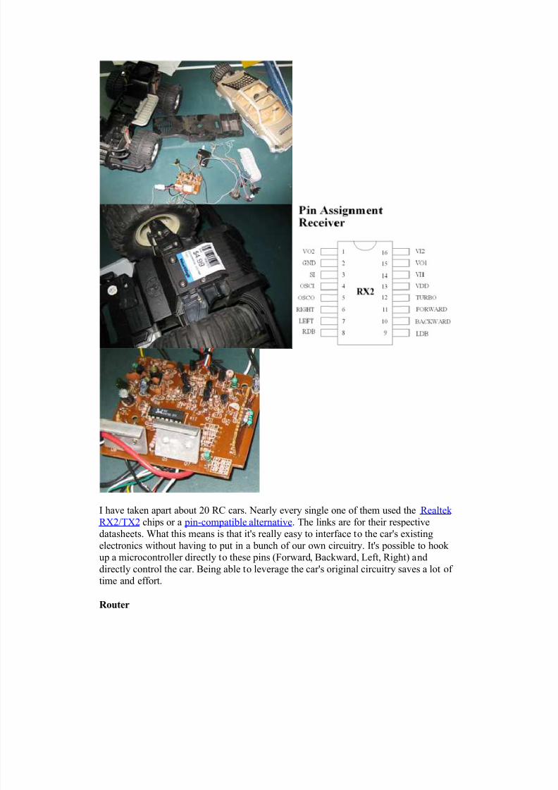
(Dimensions Images Source:http://panasonic.co.jp/pcc/products/en/netwkcam/lineup/bl-c1/partnames.html)
The video quality is quite good. However, it will often freeze at a frame for about 1second and then start streaming again. Even with good connectivity. I'm guessing itscontroller isn't powerful enough to auto-focus and also keep streaming at times. OverallI'm happy with it.
See the measurements and benchmarks section below for bandwidth requirementmeasurements.
Looking at the inside of the camera it looks like its running on an ARM processor at250MHz. According to their parts website, it also includes 64MB of RAM. I wonder how hard it would be to get Linux running on this thing...
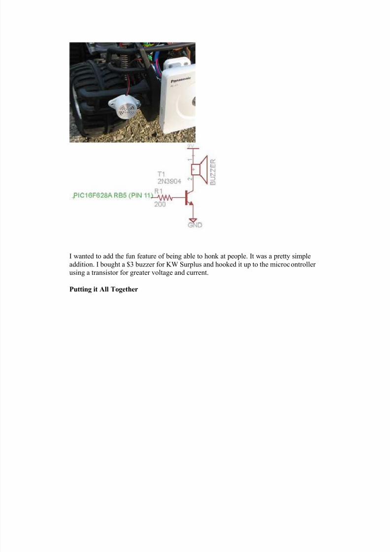
Horn
8/7/2019 o melhor projeto
http://slidepdf.com/reader/full/o-melhor-projeto 13/24
I wanted to add the fun feature of being able to honk at people. It was a pretty simpleaddition. I bought a $3 buzzer for KW Surplus and hooked it up to the microcontroller using a transistor for greater voltage and current.
Putting it All Together

8/7/2019 o melhor projeto
http://slidepdf.com/reader/full/o-melhor-projeto 14/24
8/7/2019 o melhor projeto
http://slidepdf.com/reader/full/o-melhor-projeto 15/24
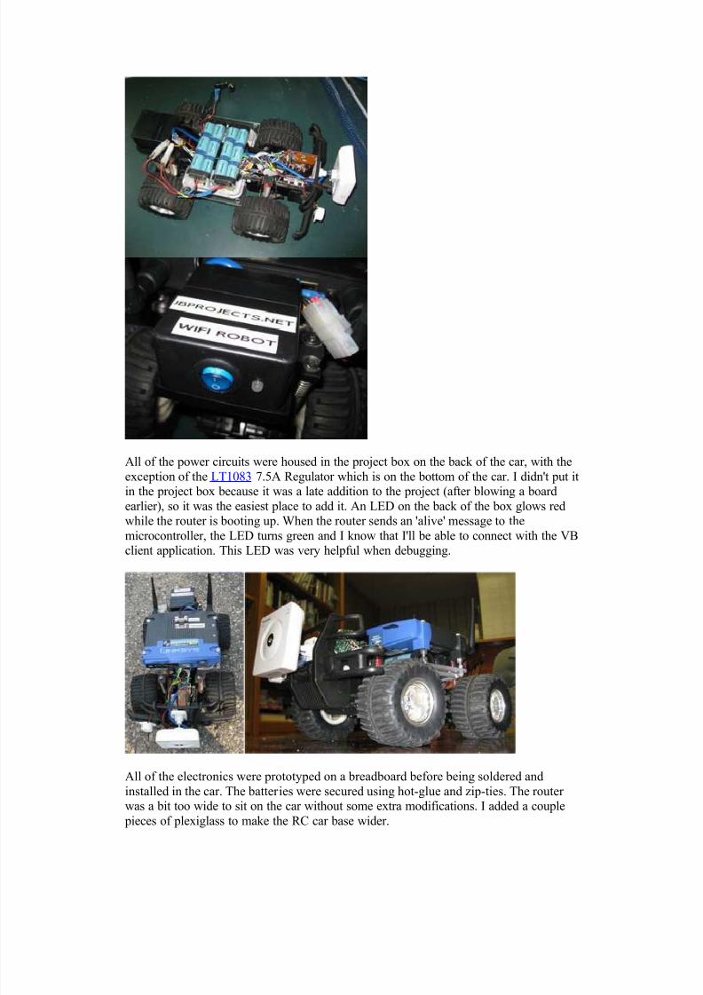
All of the power circuits were housed in the project box on the back of the car, with theexception of the LT1083 7.5A Regulator which is on the bottom of the car. I didn't put itin the project box because it was a late addition to the project (after blowing a boardearlier), so it was the easiest place to add it. An LED on the back of the box glows red
while the router is booting up. When the router sends an 'alive' message to themicrocontroller, the LED turns green and I know that I'll be able to connect with the VBclient application. This LED was very helpful when debugging.
All of the electronics were prototyped on a breadboard before being soldered andinstalled in the car. The batteries were secured using hot-glue and zip-ties. The router was a bit too wide to sit on the car without some extra modifications. I added a couplepieces of plexiglass to make the RC car base wider.
8/7/2019 o melhor projeto
http://slidepdf.com/reader/full/o-melhor-projeto 16/24
Future [Possible] Additions There are a couple things I think would be fun to add:H eadlights, just super-bright LEDs. They would be very easy to add to themicrocontroller circuit.Current Sensor that could relay back how much current the car was using and display itin the VB app. The microcontroller could read the sensor and send back the data.
Software
There are three pieces of software that make this project possible. The VB6 Wifi_Robotclient application (runs on Windows), the CarServer which is written in C and runs onthe router running OpenWRT WhiteRussian v0.9 (Linux), and the microcontroller firmware. I've provided tested firmware for both PIC16F628A microcontroller and thepopular Arduino (Freeduino MaxSerial). All software is released under the GNU GPLv2 license.
The following instructions assume you have a Linksys WRT54GL with OpenWRT
WhiteRussian v0.9 installed and connected to the internet. See this guide for OpenWRTinstallation instructions.
Installing CarServer If you just want to use the software SSH in to your router then ...# cd /tmp# wget http://www.jbprojects.net/projects/wifirobot/carserver_1_mipsel.ipk # ipkg install ./carserver_1_mipsel.ipk
Compiling and Installing CarServer If you want to see how it works or modify it yourself You'll need to download the OpenWRT SDK (Linux Only) and follow this guide for compiling software: Eric Bishop's Writing and Compiling A Simple Program for OpenWRT (just follow Part I)Makefile place in /OpenWrt-SDK-Linux-i686-1/package/carserver/ Makefile place in /OpenWrt-SDK-Linux-i686-1/package/carserver/src carserver.c place in /OpenWrt-SDK-Linux-i686-1/package/carserver/src Your compiled ipkg will show up in /OpenWrt-SDK-Linux-i686-1/bin/packages. Then# scp carserver_1_mipsel.ipk root@<router_ip>:/tmp/.to copy it to the router. SSH in and install it.
Great Resource
There seems to a free e-book on the WRT54G series of routers called the LinksysWRT54G Ultimate Hacking. I believe it's meant to be free. Google Books has the wholebook viewable. It can also be downloaded here: (password: ____ ) This book outlineshow to add a serial port, setup the software, as well as a bunch of other hacks.
Edit: (September 20, 2008)
I've been contacted by one of the authors. It isn't a free e-book. You can view the whole
book on Google Books here or for a more convenient format and to support the authors,
check it out at Amazon. It's a great book!

8/7/2019 o melhor projeto
http://slidepdf.com/reader/full/o-melhor-projeto 17/24
Getting the Serial Port Working We need to use TTS/1, so if you only add one serial port -- make sure its that one.Assuming you have OpenWRT WhiteRussian v0.9 installed, SSH in to the router. Theinstructions in the book linked above are a bit outdated. Here is the updated version:
# ipkg update
# ipkg install setserial
# cd /usr/sbin# wget http://www.jbprojects.net/projects/wifirobot/stty.tgz# tar -zxvf stty.tgz# chmod 755 stty
Add the following lines to /etc/init.d/custom-user-startup to make the serial port work on start-up and have the CarServer automatically start./usr/sbin/setserial /dev/tts/1 irq 3/usr/sbin/stty -F /dev/tts/1 raw speed 9600/bin/carserver &
Running Wifi_Robot Client App:
wifi_robot_client.zip This file contains both the VB6 source code and compiled EXE. You can just extractthe wifi_robot_client.exe and config.txt you don't want to deal with the programmingstuff. The project will open and compile in VB6 if you'd like to modify it. It's Windows-only, but if anyone wants to make an alternative client app, I'll be happy to post it hereand give you credit. This software is just slightly modified from the Computer Controller RC Car project posted a few years back.
Microcontroller Firmware
PIC You'll need a PIC programmer to burn the firmware. Personally I use a P16PRO40 thatI bought on eBay. There are many pic programmers that you can purchase or makeyourself for a few dollars worth of parts. You can compile the HEX yourself usingMicrochip's MPLAB or just download and program the HEX file provided. The PICasm is based off of this PIC16F628 UART Test guide.car_pic.asm car_pic.HEX

8/7/2019 o melhor projeto
http://slidepdf.com/reader/full/o-melhor-projeto 18/24
Arduino (Freeduino MaxSerial) You can follow these tutorials to get your Arduino up and running fast. The code can bedownloaded to the Freeduino MaxSerial without an extra programmer.car_arduino.c If you're using a Freeduino MaxSerial, make sure you complete the small hardware
modification that will stop the Freeduino from resetting every time it receives data from
the router serial port. See the hardware section above for more technical details of theproblem.
Download All Files wifi_robot_software.zip This zip-file contains all of the compiled binaries and source code mentioned above.
Disclaimer I have done my best to ensure to all information above is accurate. If there are anyerrors, please e-mail at [email protected] and I'll make any corrections.
Measurements and BenchmarksTop Speed To get the maximum speed I setup to tape lines 3m apart and filmed the car while Imade several passes. The camera records at 30fps, so I have +/- 3.3% error from thecamera and maybe +/- 1% error from the tape lines.
The car could travel 3m in 0.7 seconds (21 out of 30 frames in 1 second).Top Speed: 4.3m/s = 15.5km/h = 9.6miles/h
DistanceI took the router in to a big field. I could connect with my laptop up to 500m away (at1Mb). After that distance, I could no longer connect. The alternative firmware(OpenWRT) allows you to increase the output power. I tried modifying this value, but itmade no difference at all to the distance I was able to connect to it. Perhaps my laptop

8/7/2019 o melhor projeto
http://slidepdf.com/reader/full/o-melhor-projeto 19/24
(Dell Inspiron 6000) which has always had good wifi connectivity (better than myfriend's 6400), may be the limiting factor.
Data Rates Control Signals: 3.5KB/s Camera: 50-190KB/s
The camera used more/less bandwidth depending on how much light was in the image.If there was lots of light, it would use more bandwidth.
If the car was to be driven from very far away, the router would continually negotiate alower speed until it reached 1Mb (megabit). At this speed, the camera wouldn't be ableto send back data, but the control signals would still be working. Power Measurements
I noticed whenever the current changed during car bootup and noted the time. Themeasurements were done on the battery side before the voltage was dropped down towhatever voltage the device needed. Measurements were taken when the batteries had
been used for about 10 minutes and V=15.3V. Since the current was measured here, thecurrent going in to the device at a lower voltage would be higher. All measurementswere completed with a Fluke 187 True RMS Multimeter. The last measurement notedwas when the device reached a steady-state.
Camera
Time
(seconds) Current
(mA@ 15.3V) Current
(mA@ 9.2V) Power
(W)
0 39 65 0.6
5 58 96 0.9
8 98 163 1.5
Router
Time
(seconds) Current
(mA@ 15.3V) Current
(mA @ 12V) Power
(W)
0 185 235 2.8
23 263 335 4.0
30 250 319 3.8
Horn
Time
(seconds) Current
(mA@ 15.3V) Current
(mA@ 9.2V) Power
(W)
0 40 66 0.6
Car

8/7/2019 o melhor projeto
http://slidepdf.com/reader/full/o-melhor-projeto 20/24
State Current
(mA@
15.3V)
Current
(mA @
12V)
Power
(W)
Booting0 - 23s
Fluctuates~400
510 6.1
PIC+LED, Voltage Regulators, 2control circuit boards
(no router or camera)
102 130 1.6
After Booting, not driving(steady-state)
479 611 7.3
Driving - Accelerating 5500 7012 84.1
Driving - Constant Speed 4000 5100 61.2
Note: The driving measurements aren't as accurate because it's hard to read the
multiemeter while holding a laptop to drive the car and running down the street after
the car. heh. Those numbers are accurate +/- 0.1A. Steering takes very little power. Once the wiper circuit detects that the wheels haveturned, it stops turning them. This happens in < 1 second.
Its been my experience that the batteries last for about 1.5hrs under normal use.
Temperature / Over Heating
From the above power measurements we can see that the transistors are driving over 7A@ 12V when accelerating. They're rated for 5A, so they get pretty warm.
The transistor temperature after 25 mins of use indoors (hence lots of accelerating fromstarting and stopping and not going at max speed very often) was 89°C. The motor wasalso getting pretty warm at 85°C. When running the car outside, it doesn't seem to getnear as hot. Probably because you're driving at a constant speed more often than inside.The transistors are rated for up to 150°C, so I think we're ok. I don't have anyinformation on the motor though.
Project Costs
Item Cost*
Car 6
2nd control board(from another car)
6
Router 73
Camera 115
Batteries 67
Horn 3
PIC circuit 6

8/7/2019 o melhor projeto
http://slidepdf.com/reader/full/o-melhor-projeto 21/24
Misc: nuts, bolts,screws, project box,wires, connectors
20
Total 296
* Costs include sales tax and shipping and are rounded to the nearest dollar. Prices arein Canadian dollars.
Resources
Here are a bunch of related links that I've found informative, helpful, or interesting.
Description Link
OpenWRT, the Linux distro I'm running on the router (thispage tells you how to install)
here
WRT54G Ultimate Hacking Book Google
Books or Amazon
WRT54G hacking site affiliated with the book here
Great TCP tutorials in a bunch of different languages here
Drive transistor datasheet here
7.5A 12V regulator datasheet LT1083 here
Realtek TX2/RX2 Remote Control Car Chipset datasheet here
Pin-compatible TX2/RX2 datasheet here
Network Camera Information (Panasonic BL-C1) here
Eric Bishop's Writing and Compiling A Simple Programfor OpenWRT
here
Similar project to what I've done, but with a larger vehicleand its much slower
here
Similar project to what I've done, but with self-built H-bridge (it overheats and stops working)
here
MaxSerial Arduino-compatible Freeduino with a real DB9serial port
here
Lots of Arduino Information here
How-to for serial communication with the PIC16F628 here
If you liked the project or write-up, add a comment below or send me an e-mail [email protected] .

8/7/2019 o melhor projeto
http://slidepdf.com/reader/full/o-melhor-projeto 22/24
Comments
continued.....The error shown when i execute Rc controller is
"Component 'mswinsck.ocx' or one of its dependencies not correctly registered: a file ismissing or invalid" Please Help us
Posted by Arjun on 2011-02-27 @ 22:03
HAi sir,We completed the ipkk install section,Programmed the Arduino,But the WiFi robot client application to control it does't work in windows XP.I t5ried in my Laptop,and others also,also tried in College Netlab's Systems.
What we have to do.Please Reply me immediately....Please........
Posted by Arjun on 2011-02-27 @ 21:58
Good project!I try to do same with Dlink DIR320 with USB out and openwrt firmware
Posted by Harry on 2011-02-18 @ 00:53
Do you think is it hard to use standard camera with Eye-Fi wireless SD Card to transmitvideo. Eye-Fi has range 90 feet, so it should be conected to the router and transmit the
video through router. New c code for carserver should be written, right? I.m good at c,c++, Visual studio programming, do you have any hints for me :) Thank you very much
Posted by lilani on 2011-02-15 @ 11:27
Hello! Where can I find a truck online? I live in Italy and I can't find a RC truck...
Posted by random on 2011-02-15 @ 07:28
From the comments, I see that many people are having trouble editing the custom-user-startup. I also did not find such a file, but created one using 'vi' command. But that toodid not get my carserver start at boot(though my baud rate is always 9600 as set in thefile). What i do is, i login using putty everytime and then type 'carserver' at the console.The 'carserver' starts and you can see on the console the hex value sent to the router .
Posted by Aju Krishnan on 2011-02-8 @ 07:11
Dear Jon,I am doing the Wifi-Robot as my final year project. I have completed the OpenWRTburning and installing carserver. I can communicate to the router successfully. I have
8/7/2019 o melhor projeto
http://slidepdf.com/reader/full/o-melhor-projeto 23/24
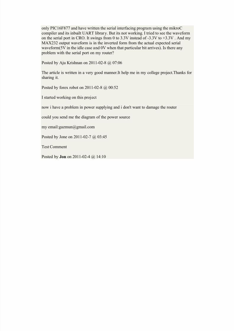
only PIC16F877 and have written the serial interfacing program using the mikroCcompiler and its inbuilt UART library. But its not working. I tried to see the waveformon the serial port in CRO. It swings from 0 to 3.3V instead of -3.3V to +3.3V . And myMAX232 output waveform is in the inverted form from the actual expected serialwaveform(5V in the idle case and 0V when that particular bit arrives). Is there anyproblem with the serial port on my router?
Posted by Aju Krishnan on 2011-02-8 @ 07:06
The article is written in a very good manner.It help me in my college project.Thanks for sharing it.
Posted by forex robot on 2011-02-8 @ 00:52
I started working on this project now i have a problem in power supplying and i don't want to damage the router
could you send me the diagram of the power source my email:[email protected]
Posted by Jone on 2011-02-7 @ 03:45
Test Comment
Posted by Jon on 2011-02-4 @ 14:10

8/7/2019 o melhor projeto
http://slidepdf.com/reader/full/o-melhor-projeto 24/24


![PROJETO VICTOR - cic.unb.brteodecampos/ViP/inazawa_etal_compBrasil2019.… · um prêmio de Melhor Artigo em conferência [3]. O projeto também foi veiculado em grandes portais de](https://static.fdocumentos.com/doc/165x107/5f1da5fb2a745978fc60adfc/projeto-victor-cicunbbr-teodecamposvipinazawaetalcompbrasil2019-um-prmio.jpg)