PERFORMANCE ASSESSMENT OF A LARGE INTERNAL …
7
Tecnologia/Technology Engenharia Térmica (Thermal Engineering), Vol. 20 • No. 2 • June 2021 • p. 13-19 13 PERFORMANCE ASSESSMENT OF A LARGE INTERNAL COMBUSTION ENGINE DUE TO INLET AIR COOLING AND DEHUMIDIFICATION: GT-POWER SOFTWARE SIMULATION I. C. Campbell a , A. Chun a , B. M. F. Miotto a J. L. M. Donatelli a , J. J. C. S. Santos a , C. C. M. Cunha a , and C. B. Zabeu b a Universidade Federal do Espírito Santo Centro Tecnológico Bairro Goiabeiras CP. 29075-910, Vitória, Espírito Santo, Brasil [email protected] [email protected] [email protected] [email protected] b Instituto Mauá de Tecnologia Departamento de Engenharia Mecânica CP. 09580900, Mauá, São Paulo, Brasil. [email protected] Received: Mar 25, 2021 Revised: Apr 01, 2021 Accepted: Apr 01, 2021 ABSTRACT Large internal combustion engines (ICEs) performance is limited by knocking phenomenon due to harsh ambient conditions such as hot temperature and excessive humidity. The performance of these engines can be enhanced by cooling and dehumidifying the inlet air on turbocharger upstream under safe operation conditions through a cooling coil heat exchanger, hence, increasing the power output as well as reducing the brake specific fuel consumption and pollutant specific emissions. Analysis have been performed in the GT-POWER software through a 1-D thermodynamic modelling of the Wärtsilä W20V34SG engine, making it possible to verify the influence of cooled and dehumidified ambient air, considering a temperature range from 9.5°C (282.7 K) to 15.5°C (288.7 K), while keeping 1 bar for pressure and relative humidity of 100%. Furthermore, the brake mean effective pressure (BMEP) has been set from 20 to 23.45 bar with a step of 1.15 bar. Such simulations are aimed to find the maximum air temperature at the cooling coil outlet in which the average of maximum cylinder pressures does not exceed the safety limit pressure of 186 bar while maintaining control on the wastegate valve. As a result, it was possible to evaluate that the maximum temperature to be chosen, under the conditions already mentioned, should be lower than 13.8°C (287 K). Keywords: internal combustion engine; intake air conditioning; 1-D thermodynamic modelling; engine performance NOMENCLATURE BMEP break mean effective pressure, bar BSFC break specific fuel consumption, g/kWh CAC charge air cooler HT high temperature, K ICE large internal combustion engine LHV lower heating value, kJ/kg LT low temperature, K T temperature, K TC turbocharger Greek symbols λ excess of air Δ difference Subscripts CA on intake manifold max maximum INTRODUCTION Regarding the scenario of Brazilian electrical energy matrix generation, the thermoelectric power plants powered with reciprocating internal combustion engine (ICE) were designed to operate as peaking power plants in an effort to bring a safer and more functional electrical energy grid. Nevertheless, for instance, the UTE LORM has been dispatched constantly, reaching 96% of active operation during a period of a year (Morawski et al., 2017; Miotto et al., 2020). Internal combustion engines performance is limited due to severe weather conditions, at high temperatures and excessive humidity, which lead to a reduction in air flow and, consequently, reduces power, efficiency and fuel consumption (Santoianni, 2015). A phenomenon known as knocking is caused by high pressures in the cylinders due to hot and humid air in the intake manifold, which may be followed by derating, because it is caused whenever the charge air temperature increases beyond a
Transcript of PERFORMANCE ASSESSMENT OF A LARGE INTERNAL …

Tecnologia/Technology
Engenharia Térmica (Thermal Engineering), Vol. 20 • No. 2 • June 2021 • p. 13-19 13
PERFORMANCE ASSESSMENT OF A LARGE INTERNAL COMBUSTION ENGINE DUE TO INLET AIR COOLING AND
DEHUMIDIFICATION: GT-POWER SOFTWARE SIMULATION
I. C. Campbella,
A. Chuna,
B. M. F. Miottoa
J. L. M. Donatellia,
J. J. C. S. Santosa,
C. C. M. Cunhaa,
and C. B. Zabeub
a Universidade Federal do Espírito Santo
Centro Tecnológico
Bairro Goiabeiras
CP. 29075-910, Vitória, Espírito Santo, Brasil
[email protected] bInstituto Mauá de Tecnologia
Departamento de Engenharia Mecânica
CP. 09580900, Mauá, São Paulo, Brasil.
Received: Mar 25, 2021
Revised: Apr 01, 2021
Accepted: Apr 01, 2021
ABSTRACT Large internal combustion engines (ICEs) performance is limited by knocking phenomenon due to harsh ambient conditions such as hot temperature and excessive humidity. The performance of these engines can be enhanced by cooling and dehumidifying the inlet air on turbocharger upstream under safe operation conditions through a cooling coil heat exchanger, hence, increasing the power output as well as reducing the brake specific fuel consumption and pollutant specific emissions. Analysis have been performed in the GT-POWER software through a 1-D thermodynamic modelling of the Wärtsilä W20V34SG engine, making it possible to verify the influence of cooled and dehumidified ambient air, considering a temperature range from 9.5°C (282.7 K) to 15.5°C (288.7 K), while keeping 1 bar for pressure and relative humidity of 100%. Furthermore, the brake mean effective pressure (BMEP) has been set from 20 to 23.45 bar with a step of 1.15 bar. Such simulations are aimed to find the maximum air temperature at the cooling coil outlet in which the average of maximum cylinder pressures does not exceed the safety limit pressure of 186 bar while maintaining control on the wastegate valve. As a result, it was possible to evaluate that the maximum temperature to be chosen, under the conditions already mentioned, should be lower than 13.8°C (287 K). Keywords: internal combustion engine; intake air conditioning; 1-D thermodynamic modelling; engine performance
NOMENCLATURE
BMEP break mean effective pressure, bar BSFC break specific fuel consumption, g/kWh CAC charge air cooler HT high temperature, K ICE large internal combustion engine LHV lower heating value, kJ/kg LT low temperature, K T temperature, K TC turbocharger Greek symbols λ excess of air Δ difference Subscripts CA on intake manifold max maximum
INTRODUCTION
Regarding the scenario of Brazilian electrical energy matrix generation, the thermoelectric power plants powered with reciprocating internal combustion engine (ICE) were designed to operate as peaking power plants in an effort to bring a safer and more functional electrical energy grid. Nevertheless, for instance, the UTE LORM has been dispatched constantly, reaching 96% of active operation during a period of a year (Morawski et al., 2017; Miotto et al., 2020). Internal combustion engines performance is limited due to severe weather conditions, at high temperatures and excessive humidity, which lead to a reduction in air flow and, consequently, reduces power, efficiency and fuel consumption (Santoianni, 2015). A phenomenon known as knocking is caused by high pressures in the cylinders due to hot and humid air in the intake manifold, which may be followed by derating, because it is caused whenever the charge air temperature increases beyond a
Tecnologia/Technology I. C. Campbell, et al. Performance Assessment of a …
14 Engenharia Térmica (Thermal Engineering), Vol. 20 • No. 2 • June 2021 • p. 13-19
designated value. Moreover, when the combustion air temperature exceeds 45°C (318.2 K), at the intake air manifold, the Wärtsilä control system causes a reduction on the brake mean effective pressure (BMEP) in order to avert knocking condition, which may harm the engine (Wärtsilä, 2008). Hence, there is an opportunity to install an absorption chiller, fueled by the residual heat rejected from de engine, in order to produce chilled water for intake air conditioning purpose.
The absolute humidity has an influence on the combustion since an increase in humidity is slowing down the combustion speed as well as reducing the maximum combustion temperature. Therefore, humidity affects the combustion efficiency in a negative way. Additionally, ambient temperature and charge air temperature positively relates with each other, and both show a positive relationship with fuel consumption and a negative one with combustion efficiency (Kahandagamage, 2015). Ambient air cooling and dehumidification, joined up to a correct additional colling in the intercooler, allow engine operations under reduced knocking condition, avoiding both derating and condensation formation in the air manifold, achieving a greater brake power output above the current rated condition of 8.7 MW, without hampering the maximum peak pressure into piston-cylinders as well as not losing control on wastegate valve.
There are several studies in literature that developed simulations through thermodynamic modellings and achieved better enhancement on Diesel engine’s performance (Mostafavi and Agnew, 1996a; Mostafavi and Agnew, 1996b; Mostafavi and Agnew, 1996c; Mostafavi and Agnew, 1997). Novella et al. (2017) carried out a study involving an absorption chiller that provided cooling effects on the intake air of an internal combustion engine, thus, reaching a theoretical addition of indicated efficiency of 4%. Kadunic et al. (2014) also studied, through experimental tests, the intake air cooling by using a jet-ejector recovering waste heat from a small gasoline engine. Their work showed some reliable improvements on the engine’s efficiency, presenting additional increasing of 18%. Zegenhagen and Ziegler (2015) conducted experimental tests with jet-ejector devices coupled with one turbocharged internal combustion engine, and, by providing more cooling effects at the charge air cooler, it was possible to reach better performance.
The goal of this paper is to present and discuss the results of a Wärtsilä W20V34SG engine simulation, through a 1-D thermodynamic modelling on GT-POWER software, by considering a wide range of cooled and dehumidified air condition at the compressor’s inlet. The case study was one of the 24 generators set of the Luiz Oscar Rodrigues de Melo Thermoelectric Power Plant (UTE LORM), which is located in Linhares city, state of Espírito Santo,
Brazil. It was possible to simulate the effect of the turbocharger inlet air on the engine shaft power, specific fuel consumption, wastegate mass flow, etc. These analyses aimed to find the maximum temperature of the turbocharger inlet conditioned air in which the average of maximum cylinder pressures does not exceed the safety limit pressure of 186 bar, while maintaining control on the wastegate valve, which must stay open to limits the boost pressure in the turbocharger, by protecting the engine. METHODOLOGY
The simulations are carried out by utilizing a 1-
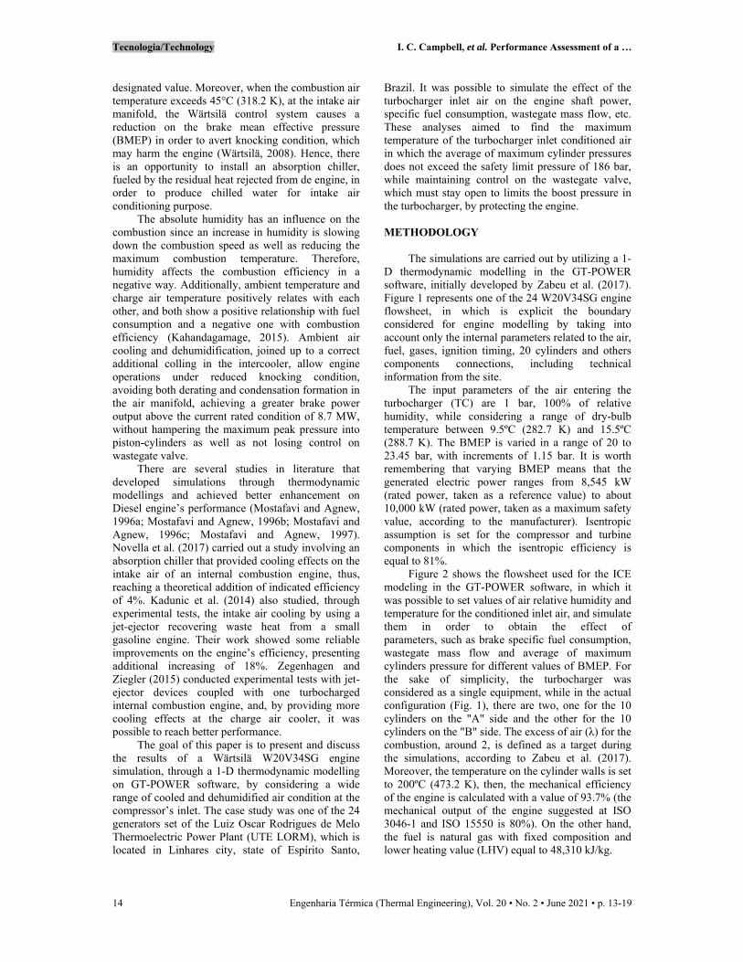
D thermodynamic modelling in the GT-POWER software, initially developed by Zabeu et al. (2017). Figure 1 represents one of the 24 W20V34SG engine flowsheet, in which is explicit the boundary considered for engine modelling by taking into account only the internal parameters related to the air, fuel, gases, ignition timing, 20 cylinders and others components connections, including technical information from the site.
The input parameters of the air entering the turbocharger (TC) are 1 bar, 100% of relative humidity, while considering a range of dry-bulb temperature between 9.5ºC (282.7 K) and 15.5ºC (288.7 K). The BMEP is varied in a range of 20 to 23.45 bar, with increments of 1.15 bar. It is worth remembering that varying BMEP means that the generated electric power ranges from 8,545 kW (rated power, taken as a reference value) to about 10,000 kW (rated power, taken as a maximum safety value, according to the manufacturer). Isentropic assumption is set for the compressor and turbine components in which the isentropic efficiency is equal to 81%.
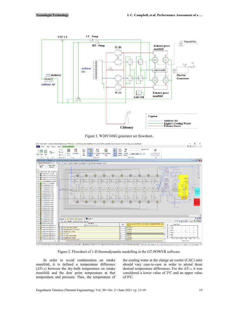
Figure 2 shows the flowsheet used for the ICE modeling in the GT-POWER software, in which it was possible to set values of air relative humidity and temperature for the conditioned inlet air, and simulate them in order to obtain the effect of parameters, such as brake specific fuel consumption, wastegate mass flow and average of maximum cylinders pressure for different values of BMEP. For the sake of simplicity, the turbocharger was considered as a single equipment, while in the actual configuration (Fig. 1), there are two, one for the 10 cylinders on the "A" side and the other for the 10 cylinders on the "B" side. The excess of air (λ) for the combustion, around 2, is defined as a target during the simulations, according to Zabeu et al. (2017). Moreover, the temperature on the cylinder walls is set to 200ºC (473.2 K), then, the mechanical efficiency of the engine is calculated with a value of 93.7% (the mechanical output of the engine suggested at ISO 3046-1 and ISO 15550 is 80%). On the other hand, the fuel is natural gas with fixed composition and lower heating value (LHV) equal to 48,310 kJ/kg.
Tecnologia/Technology I. C. Campbell, et al. Performance Assessment of a …
Engenharia Térmica (Thermal Engineering), Vol. 20 • No. 2 • June 2021 • p. 13-19 15
Figure 1. W20V34SG generator set flowsheet.
Figure 2. Flowsheet of 1-D thermodynamic modelling in the GT-POWER software.
In order to avoid condensation on intake manifold, it is defined a temperature difference (ΔTCA) between the dry-bulb temperature on intake manifold and the dew point temperature at that temperature and pressure. Thus, the temperature of
the cooling water at the charge air cooler (CAC) inlet should vary case-to-case in order to attend these desired temperature differences. For the ΔTCA, it was considered a lower value of 2ºC and an upper value of 8ºC.
Tecnologia/Technology I. C. Campbell, et al. Performance Assessment of a …
16 Engenharia Térmica (Thermal Engineering), Vol. 20 • No. 2 • June 2021 • p. 13-19
These simulations aim to find the maximum air temperature at the cooling coil outlet, as this will determine the demand for chilled water to be used in the thermal system to be installed, once it allows the engine to reach the maximum power of 10,000 kW without hampering the cylinders peak pressure of 186 bar, which is the safety limit pressure stablished by the manufacturer, while maintaining control on the wastegate valve. Therefore, carrying out the simulation using GT-POWER software, it was possible to analyze various parameters on the engine performance indicator, mainly, the brake specific fuel
consumption (BSFC), wastegate mass flow rate and the maximum allowed average cylinder pressure.
RESULTS AND DISCUSSIONS
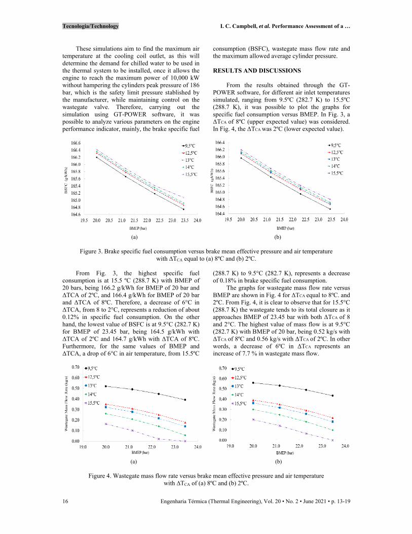
From the results obtained through the GT-POWER software, for different air inlet temperatures simulated, ranging from 9.5ºC (282.7 K) to 15.5ºC (288.7 K), it was possible to plot the graphs for specific fuel consumption versus BMEP. In Fig. 3, a ΔTCA of 8ºC (upper expected value) was considered. In Fig. 4, the ΔTCA was 2ºC (lower expected value).
(a) (b)
Figure 3. Brake specific fuel consumption versus brake mean effective pressure and air temperature with ∆TCA equal to (a) 8ºC and (b) 2ºC.
From Fig. 3, the highest specific fuel consumption is at 15.5 ºC (288.7 K) with BMEP of 20 bars, being 166.2 g/kWh for BMEP of 20 bar and ΔTCA of 2ºC, and 166.4 g/kWh for BMEP of 20 bar and ΔTCA of 8ºC. Therefore, a decrease of 6°C in ΔTCA, from 8 to 2°C, represents a reduction of about 0.12% in specific fuel consumption. On the other hand, the lowest value of BSFC is at 9.5°C (282.7 K) for BMEP of 23.45 bar, being 164.5 g/kWh with ΔTCA of 2ºC and 164.7 g/kWh with ΔTCA of 8ºC. Furthermore, for the same values of BMEP and ΔTCA, a drop of 6°C in air temperature, from 15.5ºC
(288.7 K) to 9.5°C (282.7 K), represents a decrease of 0.18% in brake specific fuel consumption.
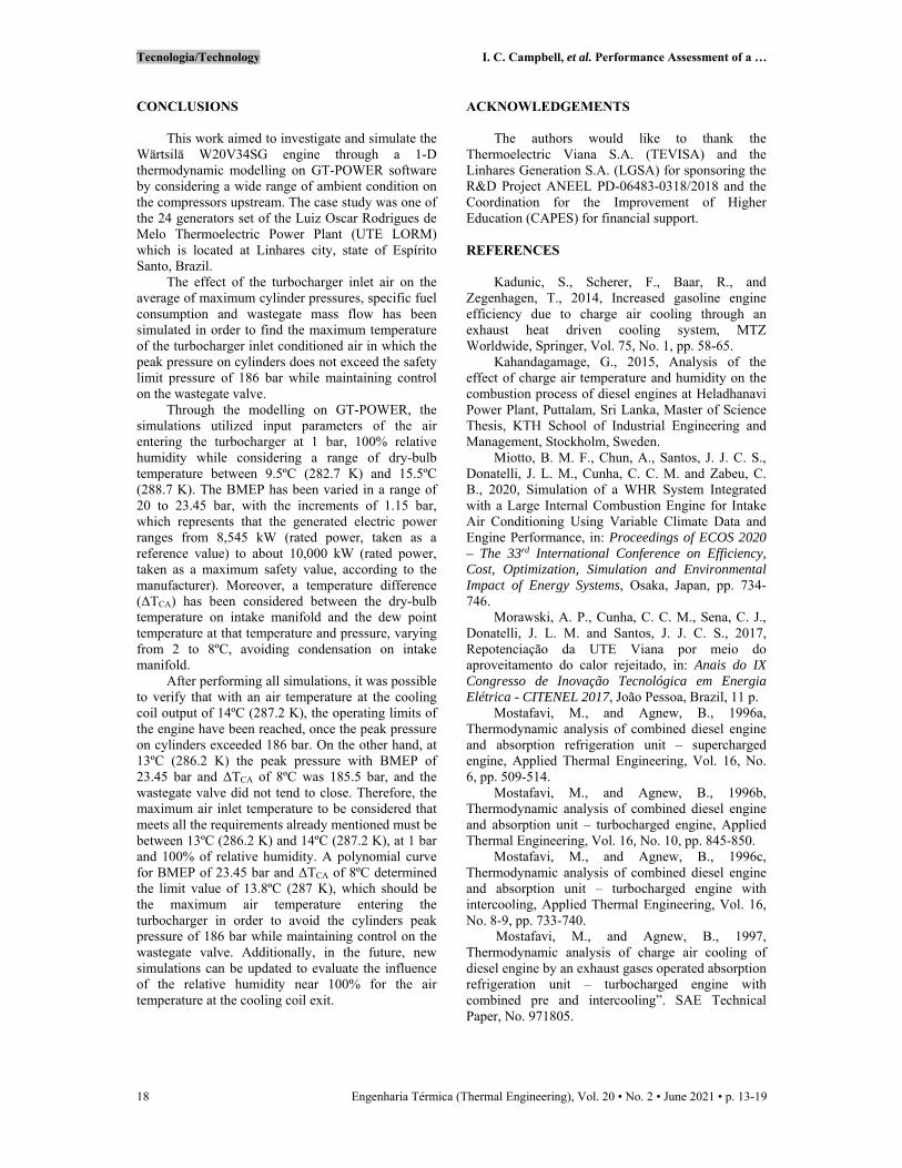
The graphs for wastegate mass flow rate versus BMEP are shown in Fig. 4 for ΔTCA equal to 8ºC. and 2ºC. From Fig. 4, it is clear to observe that for 15.5°C (288.7 K) the wastegate tends to its total closure as it approaches BMEP of 23.45 bar with both ΔTCA of 8 and 2°C. The highest value of mass flow is at 9.5°C (282.7 K) with BMEP of 20 bar, being 0.52 kg/s with ΔTCA of 8ºC and 0.56 kg/s with ΔTCA of 2ºC. In other words, a decrease of 6ºC in ΔTCA represents an increase of 7.7 % in wastegate mass flow.
(a) (b)
Figure 4. Wastegate mass flow rate versus brake mean effective pressure and air temperature with ∆TCA of (a) 8ºC and (b) 2ºC.

Tecnologia/Technology I. C. Campbell, et al. Performance Assessment of a …
Engenharia Térmica (Thermal Engineering), Vol. 20 • No. 2 • June 2021 • p. 13-19 17
The graphs for average of maximum cylinder pressures versus BMEP are shown in Fig. 5 with ΔTCA of 8ºC and 2ºC. According to Fig. 5, for intake air temperature higher than 14ºC (287.2 K), when BMEP is 23.45 bar, the peak pressure overcomes 186 bar, the limit pressure stablished by the manufacturer,
and may cause the knocking effect. However, for 13°C (286.2 K), the peak pressure on cylinders, when BMEP is 23.45 bar and ΔTCA of 8ºC is 185.5 bar, which does not reach the safety limit. Therefore, the maximum air inlet temperature must be lower than 14ºC (287.2 K).
(a) (b)
Figure 5. Average of maximum cylinder pressures versus brake mean effective pressure and air temperature with ∆TCA equal to (a) 8ºC and (b) 2ºC.
The air conditioning of the engine in the cooling coil of the thermal system, including the cooling of this air in the charge air cooler (CAC) after its compression, aims to allow an increase of engine power to about 10,000 kW. Thus, for this high power, already with an air temperature at the cooling coil output of 14ºC (287.2 K), the operating limits of the engine are reached, once that the safety engine operation requires a flow rate in the turbocharger gas diversion valve (wastegate valve) above zero, as well as an average maximum cylinder pressure lower than 186 bar. Figure 6a shows that the safety engine
operation requires an air dry-bulb temperature, at the cooling coil’s exit, lower than 13.8°C. It presents the results obtained for the maximum BMEP of 23.45 bar with different values of ΔTCA in order to find the maximum air dry-bulb temperature, at the cooling coil’s exit, in which the maximum pressure of peak pressures on cylinders that do not exceed the safety limit of 186 bar. For the same maximum BMEP of 23.45 bar and different values of ΔTCA, Figure 6b shows that the flow rate in the gas diversion valve (wastegate valve) is greater than zero for those situations.
(a) (b)
Figure 6. (a) Average of maximum cylinder pressures and (b) wastegate mass flow versus compressor inlet air temperature and ∆TCA with BMEP of 23.45 bar.
Tecnologia/Technology I. C. Campbell, et al. Performance Assessment of a …
18 Engenharia Térmica (Thermal Engineering), Vol. 20 • No. 2 • June 2021 • p. 13-19
CONCLUSIONS
This work aimed to investigate and simulate the Wärtsilä W20V34SG engine through a 1-D thermodynamic modelling on GT-POWER software by considering a wide range of ambient condition on the compressors upstream. The case study was one of the 24 generators set of the Luiz Oscar Rodrigues de Melo Thermoelectric Power Plant (UTE LORM) which is located at Linhares city, state of Espírito Santo, Brazil.
The effect of the turbocharger inlet air on the average of maximum cylinder pressures, specific fuel consumption and wastegate mass flow has been simulated in order to find the maximum temperature of the turbocharger inlet conditioned air in which the peak pressure on cylinders does not exceed the safety limit pressure of 186 bar while maintaining control on the wastegate valve.
Through the modelling on GT-POWER, the simulations utilized input parameters of the air entering the turbocharger at 1 bar, 100% relative humidity while considering a range of dry-bulb temperature between 9.5ºC (282.7 K) and 15.5ºC (288.7 K). The BMEP has been varied in a range of 20 to 23.45 bar, with the increments of 1.15 bar, which represents that the generated electric power ranges from 8,545 kW (rated power, taken as a reference value) to about 10,000 kW (rated power, taken as a maximum safety value, according to the manufacturer). Moreover, a temperature difference (ΔTCA) has been considered between the dry-bulb temperature on intake manifold and the dew point temperature at that temperature and pressure, varying from 2 to 8ºC, avoiding condensation on intake manifold.
After performing all simulations, it was possible to verify that with an air temperature at the cooling coil output of 14ºC (287.2 K), the operating limits of the engine have been reached, once the peak pressure on cylinders exceeded 186 bar. On the other hand, at 13ºC (286.2 K) the peak pressure with BMEP of 23.45 bar and ΔTCA of 8ºC was 185.5 bar, and the wastegate valve did not tend to close. Therefore, the maximum air inlet temperature to be considered that meets all the requirements already mentioned must be between 13ºC (286.2 K) and 14ºC (287.2 K), at 1 bar and 100% of relative humidity. A polynomial curve for BMEP of 23.45 bar and ΔTCA of 8ºC determined the limit value of 13.8ºC (287 K), which should be the maximum air temperature entering the turbocharger in order to avoid the cylinders peak pressure of 186 bar while maintaining control on the wastegate valve. Additionally, in the future, new simulations can be updated to evaluate the influence of the relative humidity near 100% for the air temperature at the cooling coil exit.
ACKNOWLEDGEMENTS
The authors would like to thank the Thermoelectric Viana S.A. (TEVISA) and the Linhares Generation S.A. (LGSA) for sponsoring the R&D Project ANEEL PD-06483-0318/2018 and the Coordination for the Improvement of Higher Education (CAPES) for financial support.
REFERENCES
Kadunic, S., Scherer, F., Baar, R., and Zegenhagen, T., 2014, Increased gasoline engine efficiency due to charge air cooling through an exhaust heat driven cooling system, MTZ Worldwide, Springer, Vol. 75, No. 1, pp. 58-65. Kahandagamage, G., 2015, Analysis of the effect of charge air temperature and humidity on the combustion process of diesel engines at Heladhanavi Power Plant, Puttalam, Sri Lanka, Master of Science Thesis, KTH School of Industrial Engineering and Management, Stockholm, Sweden. Miotto, B. M. F., Chun, A., Santos, J. J. C. S., Donatelli, J. L. M., Cunha, C. C. M. and Zabeu, C. B., 2020, Simulation of a WHR System Integrated with a Large Internal Combustion Engine for Intake Air Conditioning Using Variable Climate Data and Engine Performance, in: Proceedings of ECOS 2020 – The 33rd International Conference on Efficiency,Cost, Optimization, Simulation and EnvironmentalImpact of Energy Systems, Osaka, Japan, pp. 734-746.
Morawski, A. P., Cunha, C. C. M., Sena, C. J., Donatelli, J. L. M. and Santos, J. J. C. S., 2017, Repotenciação da UTE Viana por meio do aproveitamento do calor rejeitado, in: Anais do IX Congresso de Inovação Tecnológica em Energia Elétrica - CITENEL 2017, João Pessoa, Brazil, 11 p.
Mostafavi, M., and Agnew, B., 1996a, Thermodynamic analysis of combined diesel engine and absorption refrigeration unit – supercharged engine, Applied Thermal Engineering, Vol. 16, No. 6, pp. 509-514.
Mostafavi, M., and Agnew, B., 1996b, Thermodynamic analysis of combined diesel engine and absorption unit – turbocharged engine, Applied Thermal Engineering, Vol. 16, No. 10, pp. 845-850.
Mostafavi, M., and Agnew, B., 1996c, Thermodynamic analysis of combined diesel engine and absorption unit – turbocharged engine with intercooling, Applied Thermal Engineering, Vol. 16, No. 8-9, pp. 733-740.
Mostafavi, M., and Agnew, B., 1997, Thermodynamic analysis of charge air cooling of diesel engine by an exhaust gases operated absorption refrigeration unit – turbocharged engine with combined pre and intercooling”. SAE Technical Paper, No. 971805.

Tecnologia/Technology I. C. Campbell, et al. Performance Assessment of a …
Engenharia Térmica (Thermal Engineering), Vol. 20 • No. 2 • June 2021 • p. 13-19 19
Novella, R., Dolz, V., Martín, J., and Royo-Pascual, L., 2017, Thermodynamic analysis of an absorption refrigeration system used to cool down the intake air in an internal combustion engine, Applied Thermal Engineering, Vol. 111, pp. 257-270. Santoianni, D., 2015, Power plant performance under extreme ambient conditions, Technical Report No.: J 2015: 22-27, Wärtsilä, Finland.
Wärtsilä, 2008, Wärtsila 34SG Power Plant Product Guide, Technical Report, Wärtsilä, Finland.
Zabeu, C. B., Salvador, R. L., Ruy, G. P., Martelli, A. L., Penaranda, A. M., and Güntert, T. S., 2017, Sistema integrado de monitoramento, diagnóstico e controle de motores pesados a gás natural de alta eficiência para geração de energia, in: Anais do IX Congresso de Inovação Tecnológica em Energia Elétrica - CITENEL 2017, João Pessoa, Brazil, 12 p.
Zegenhagen, M., and Ziegler, F., 2015. Feasibility analysis of an exhaust gas waste heat driven jet-ejector cooling system for charge air cooling of turbocharged gasoline engines, Applied Energy, Elsevier, Vol. 160, pp. 221-230.