PLT unit - brand.de · O valor pV é o produto da pressão e do volume de uma certa quantidade de...
70
Pipette Leak Testing Unit PLT unit Manual de operação · Operating Manual
Transcript of PLT unit - brand.de · O valor pV é o produto da pressão e do volume de uma certa quantidade de...

Pipet te Leak Test ing Un i tPLT un i t
Manual de operação · Operating Manual

Po
rtu
gu
ês
Índice
3
Página
Instruções de Segurança 4
Marca CE 5
Funções e Limitações de uso 5
Operações não recomendadas 5
Elementos de Operação 6
Primeiros passos 7
Inicialização 7
Auto teste 8
Teste rápido 8
Teste completo 10
Preparo para o teste 12
Teste dinâmico ou estático? 12
Teste com ou sem ponteira? 12
Adaptadores para mono ou multicanal 13
Troca do adaptador e filtro 14
Teste de pipetas monocanal 15
Teste de pipetas multicanal 18
Desligar o equipamento 21
Ajustes 22
Seleção de linguagem 22
Ajuste do contraste do display 23
Configuração da data de inspeção 24
Configuração do tempo de desligamento automático 25
Seleção das unidades de pressão (hPa, mbar, torr) 26
Restauração das configurações de fábrica 27
Atualização da versão via interface USB 28
Tabela de correlação de Taxa de vazamento/volume 29
Informações de pedido · Acessórios · Peças de reposição 30
Resolução de problemas 31
Informações de reparo · Endereços de contato 32
Garantia 33
Descarte 34

Por favor leia com atenção as informações a seguir!
Eventualmente, este instrumento pode ser utilizado com materiais, operações e equipamentos perigosos. Está além do escopo deste manual abordar todos os riscos de segurança potenciais associados com seu uso nestas aplicações. É responsabilidade do usuário do instrumento consultar e estabelecer práticas de segurança e saúde além de determinar a aplicabilidade de limitações legais antes da utilização.
Instruções de Segurança
!
1. Todos os usuários devem ler e compreender este manual de operação antes de utilizar o instrumento.
2. Siga as instruções gerais para prevenção de acidentes e instruções de segurança; ex. Usar roupas protetoras, óculos de proteção e luvas. Quando trabalhar com amostras infecciosas ou perigosas, todos os regulamentos e precau-ções devem ser seguidos.
3. Nunca utilize o instrumento em atmosferas com risco de explosão.
4. Use o instrumento somente para teste de vazamento de pipetas que operam com o princípio de deslocamento de ar. Observe as operações não recomendadas (veja pág. 5). Em caso de dúvida, contate o fabricante ou fornecedor.
5. Sempre utilize o instrumento de forma que nem o usuário e nem outras pessoas estejam em risco.
6. Quando testar micropipetas com ponteiras montadas, utilize somente ponteiras sem uso.
7. Nunca use força sobre o instrumento.
8. Somente use peças de reposição originais. Não tente realizar nenhuma alteração técnica.
9. Somente pessoal de serviço autorizado podem reparar ou realizar serviços no instrumento.
10. Antes do uso, sempre verifique o instrumento quanto a defeitos visíveis. Em caso de sinais de problemas potenciais, pare imediatamente o teste. Consulte a seção “Resolução de Proble-mas” neste manual (veja pág. 31), e contate o fabricante caso necessário.
11. O adaptador AC deve ser protegido contra umidade e somente deve ser utilizado para este instrumento.
4
Aviso!
O uso impróprio do instrumento (curto-circuito, defeito mecânico, supera-quecimento, etc.) pode causar explosão.

Po
rtu
gu
ês
Funções e Limitações de Uso
O instrumento para teste de vazamento da BRAND é um instrumento de medição de pressão diferen-cial para determinação da taxa de vazamento de pipetas de deslocamento de ar. Os testes estático e dinâmico permitem a localização dos vazamentos. O teste dinâmico é preferível.
É possível realizar o teste com ponteira (para testar o sistema completo e interface instrumento/pon-teira) e sem ponteira (para testar o instrumento). A taxa de vazamento está diretamente relacionada à perda de volume da pipeta.
A taxa de vazamento QL é a medida da quantidade de material (massa) que flui através do vazamento por unidade de tempo.
O instrumento oferece um teste rápido e simples de vazamentos em pipetas de deslocamento de ar, dentro das seguintes limitações físicas:
– Temperatura de ambos, instrumento e solução, entre 15 °C a 35 °C.
– Umidade relativa máx. 80%
– Uso em altitudes de até 2000 m acima do nível do mar.
- Temperatura de armazenamento entre 0 °C a 50 °C.
Limitações de Uso Operações não recomendadas
Os próprios usuários devem verificar se o instrumen-to é adequado para a aplicação pretendida.
Não use o equipamento para aspirar líquidos!
Evite vapores agressivos (perigo de corrosão)! Maio-res informações disponíveis sob consulta.
Recipientes vazios que não são específicos para vácuo, nunca devem ser expostos ao vácuo, pois podem romper!
A taxa de vazamento é a razão do valor de pV de um gás e o período de tempo durante o qual o gás flui através do vazamento. O valor pV é o produto da pressão e do volume de uma certa quantidade de gás na temperatura corrente. Em gases ideais, o valor de pV em uma dada temperatura é a medi-da da quantidade de material ou massa do gás. A taxa de vazamento depende do tipo de gás, pres-são absoluta, diferença de pressão e temperatura.Para o teste das pipetas, hPa ml/s é a unidade apropriada para a taxa de vazamento QL. Uma taxa de vazamento de 1 hPa ml/s em uma pressão do ar de 1000 hPA significa uma perda de volume de 1 μl/s.
Esta marca certifica que o produto atende aos requerimentos das diretivas EC e foi testado de acordo com os métodos especificados.
Marca CE
O teste de vazamento não pode substituir o teste gravimétrico para o monitoramento de instrumentos de medição. O instrumento deve ser utilizado para verificar pipetas diariamente como segurança entre os períodos de calibração.
Especificações de bateriaImportante!
PLT unit:
Entrada: DC 6.5 V= 800 mA
Adaptador AC:
Entrada: AC 100 V - 240 V, 50/60 Hz, 0,5 ASaída: DC 6,5 V= 800 mAClasse de proteção: IP20
Quando o instrumento for realocado para um novo local ou mesmo durante transporte, mudanças sig-nificativas na temperatura e umidade atmosférica podem afetar o instrumento.Para evitar mensagens de erro, a Unidade PLT deve aclimatizar no laboratório de teste por um período de 2 horas antes do uso!
5
Observação:

Elementos de Operação
De acordo com a ISO 8655, pipetas de deslocamento de ar devem ser verificadas regularmente.A Unidade PLT BRAND oferece uma salvaguarda para os períodos entre os intervalos de calibração.
Adaptador mono-canal
Botão "Voltar"
Adaptador AC
"Botão/Início" Executar
Botão de seleção Display LED
Display
Porta USB
Parte traseira do instrumento
A função do botão “Vol-tar varia ao pressioná-lo por um período curto ou longo de tempo. Pres-sionar por um período curto reconduz ao sub-menu de maior nível hierárquico. Pressionar por um período longo de tempo reconduz direta-mente à posição “Ready” (Pronto) no Menu Inicial.
Botão "Voltar" Botão de Seleção
Em muitos casos, o bo-tão à esquerda “Iniciar/Executar” ou o botão de seleção podem ser utilizados para confirmar uma seleção. Para con-sistência, o botão à es-querda “Iniciar/Executar” é utilizado para confirma-ção neste manual.
6

Po
rtu
gu
ês
A embalagem está completa?
A embalagem contém a Unidade PLT, um adaptador de cada, para teste com ponteira (montado) e sem ponteira, 2 plugs cegos, 3 filtros de reposição em PE para os adaptadores, um adaptador AC, um certificado de qualidade e o Manual de Operação.
Primeiros Passos
Use somente a fonte AC original!
A fonte AC do instrumento e o conector AC devem estar livremente acessíveis e fáceis de desconectar da rede elétrica a qual-quer momento
LanguageDeutschEnglishEspañol
o.k.
SettingsLanguageContrastInspection dateAuto-Power-Off Timeselect back
O que fazer? Como fazer Botões a pressionar Leitura no display
Conecte a fonte AC ao soquete na parte traseira do instrumento, sem pressionar nenhum botão no instru-mento.
Após conectar a fonte AC, o display mostra a versão do software, a data de criação e a logomarca BRAND.
Durante a inicialização, o display mostra o indicador “Idioma” após 3 segundos.
1. Conectar a fonte AC
Para selecionar o idioma, gire o botão de seleção.
2. Selecionar o idioma
Pressione o botão à esquer-da “OK”. As configurações no Menu aparecem no idioma sele-cionado.
O botão “Voltar” reconduz ao Menu principal.
3. Confirmar o idioma
LanguageDeutschEnglishEspañol
o.k.
Após a inicialização, é possível realizar o auto-teste (veja pág. 8) ou diretamente começar um teste de pipeta (pág.12).
Ligar o instrumento
Observação:
7
V1.40.0113-Mar-2011
Firmware
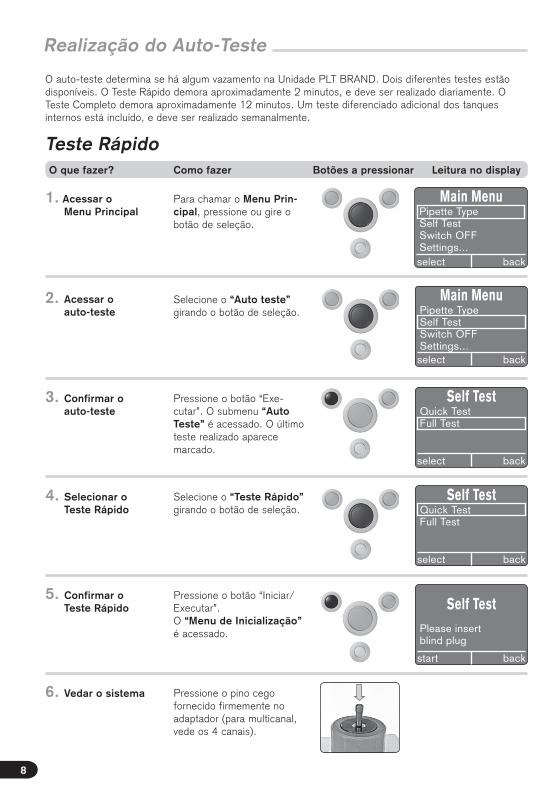
O auto-teste determina se há algum vazamento na Unidade PLT BRAND. Dois diferentes testes estão disponíveis. O Teste Rápido demora aproximadamente 2 minutos, e deve ser realizado diariamente. O Teste Completo demora aproximadamente 12 minutos. Um teste diferenciado adicional dos tanques internos está incluído, e deve ser realizado semanalmente.
Realização do Auto-Teste
Teste Rápido
Para chamar o Menu Prin-cipal, pressione ou gire o botão de seleção.
Selecione o “Auto teste” girando o botão de seleção.
Pressione o botão “Exe-cutar”. O submenu “Auto Teste” é acessado. O último teste realizado aparece marcado.
1. Acessar o Menu Principal
2. Acessar o auto-teste
3. Confirmar o auto-teste
Selecione o “Teste Rápido” girando o botão de seleção.
Pressione o botão “Iniciar/Executar”.O “Menu de Inicialização” é acessado.
4. Selecionar o Teste Rápido
5. Confirmar o Teste Rápido
6. Vedar o sistema
select back
Main MenuPipette TypeSelf TestSwitch OFFSettings...
Main MenuPipette TypeSelf TestSwitch OFFSettings...select back
Self TestQuick TestFull Test
select back
Self TestPlease insertblind plug
start back
Self TestQuick TestFull Test
select back
Pressione o pino cego fornecido firmemente no adaptador (para multicanal, vede os 4 canais).
O que fazer? Como fazer Botões a pressionar Leitura no display
8
select back

Po
rtu
gu
ês
Pressione o botão “Iniciar/Executar”. Os cinco com-ponentes – sensor, bomba, válvula, filtro e câmara de medição - são testados um após o outro. A barra de progresso no display indica o estado do teste. O indicador LED pisca alternadamente entre vermelho e verde durante o teste.
Após completar os testes dos componentes, o display mostra uma mensagem para remover o pino.
Remova o pino e pressione o botão “Executar”. O sistema é aerado e o indicador mostra a pressão atual na câmara de medição.
7. Iniciar o Teste Rápido
8. Aeração o sistema
Após aerar o sistema, o display muda automatica-mente e indica se a Unidade passou no teste. Em caso de erro, o sistema para o procedimento e indica um código de erro (veja pág.), e o sistema é aerado.
O teste pode ser repetido ao pressionar o botão “Iniciar/Executar”. O botão “Voltar” leva diretamente ao Menu Principal.
9. Finalizar o auto-teste
Realização do Auto-Teste
Self TestPlease removeblind plug
continue back
Self TestPASS
restart back
Self Test
-0.10 hPa 1:sensor
back
Self Test
-20.10 hPa
back
(O valor da pressão é apenas um exemplo)
(O valor da pressão é apenas um exemplo)
Verde
Vermelho
Self Test
error: 1XXXsee instruction manual
backrestart
O que fazer? Como fazer Botões a pressionar Leitura no display
9

–
O auto-teste determina se há algum vazamento na Unidade PLT BRAND. Dois diferentes testes estãodisponíveis. O Teste Rápido demora aproximadamente 2 minutos, e deve ser realizado diariamente. OTeste Completo demora aproximadamente 12 minutos. Um teste diferenciado adicional dos tanquesinternos está incluído, e deve ser realizado semanalmente.
Realização do Auto-Teste
Teste completo
Para chamar o Menu Prin-cipal, pressione ou gire obotão de seleção.
Selecione o “Auto teste”girando o botão de seleção.
Pressione o botão “Ex-ecutar”. O submenu “AutoTeste” é acessado. O últimoteste realizado aparecemarcado.
1. Acessar o Menu Principal
2. Acessar o auto-teste
3. Confirmar o auto-teste
Selecione o “Teste Completo” girando o botão de seleção.
Pressione o botão “Iniciar/Executar”.O “Menu de Inicialização”é acessado.
Pressione o pino cegofornecido firmemente noadaptador (para multicanal,vede os 4 canais).
4. Selecionar o Teste Rápido
5. Confirmar o Teste Completo
6. Vedar o Sistema
Main MenuPipette TypeSelf TestSwitch OFFSettings...select back
Main MenuPipette TypeSelf TestSwitch OFFSettings...select back
Self TestQuick TestFull Test
select back
Self TestPlease insertblind plug
start back
Self TestQuick TestFull Test
select back
O que fazer? Como fazer Botões a pressionar Leitura no display
10

Po
rtu
gu
ês
Pressione o botão “Iniciar/Executar”. Os seis compo-nentes – sensor, bomba,válvula, filtro e câmara e os tanques - são testados umapós o outro. A barra deprogresso no display indica oestado do teste. O indicadorLED pisca alternadamenteentre vermelho e verdedurante o teste.
Após completar os testesdos componentes, o displaymostra uma mensagem pararemover o pino.
Remova o pino e pressione obotão “Executar”. O sistemaé aerado e o indicadormostra a pressão atual nacâmara de medição.
7. Iniciar o Teste Completo
8. Aeração do sistema
Após aerar o sistema, o display muda automatica-mente e indica se a Unidade passou no teste. Em caso de erro, o sistema para o procedimento e indica um código de erro (veja pág. 32), e o sistema é aerado.
O teste pode ser repetido aopressionar o botão “Iniciar/Executar”. O botão “Voltar”leva diretamente ao MenuPrincipal.
9. Finalizar o auto-teste
Realização do Auto-Teste
Self TestPlease removeblind plug
continue back
Self TestPASS
restart back
Self Test
-0.10 hPa 1:sensor
back
Self Test
-20.10 hPa
back
(O valor da pressão é apenas um exemplo)
(pressure value is only an example)
Verde
Vermelho
Self Test
error: 1XXXsee instruction manual
backrestart
O que fazer? Como fazer Botões a pressionar Leitura no display
11

Preparo do teste
Antes do teste, é necessário decidir se um teste estático ou dinâmico será realizado.
Com o teste dinâmico, além da detecção de vazamentos estáticos, é possí-vel determinar se um pistão defeituoso (contaminação, arranhões) é a causa do vazamento.
Durante o tempo de medição, o botão de pipetagem deve ser pressionado para baixo completamente por 2 ou 3 vezes. O movimento do pistão associa-do, permite que erros sejam reconhecidos.
O acionamento do botão de pipetagem deve ser realizado relativamente deva-gar com pipetas de 5ml e 10ml.
No teste dinâmico, o pistão deve estar inicialmente na posição superior, e deve voltar a esta posição no final.
No teste estático entretanto, o botão de pipetagem não é pressionado durante o procedimento de teste, isto é, o pistão não se move. Em pipetas eletrônicas, primeiramente se deve posicionar o pistão na posição superior ou na primeira parada. Um vazamento que ocorre durante o acionamento do pistão pode não ser determinado neste ponto.
Recomendamos que o teste dinâmico seja realizado.
Teste estático ou dinâmico
O teste pode ser realizado com ou sem ponteira.
Recomendamos que o teste seja realizado com uma ponteira sem uso mon-tada, para que o sistema inteiro seja testado.
Quando um vazamento é identificado, o teste pode ser repetido sem a pon-teira para determinar se o vazamento provém da região do cone de acopla-mento da ponteira.
O adaptador deve ser substituído (veja pág. 14) para que seja possível reali-zar o teste sem a ponteira.
Deve-se segurar firmemente a pipeta durante o teste.
Teste com ou sem ponteira?
12

Po
rtu
gu
ês
Para proteger o instrumento contra umidade e contaminação, um filtro de PE facilmente substituível está incluído na parte inferior do adaptador de silicone.
1
2
3
Substituição do adaptador
No total, 3 adaptadores estão disponíveis.
Adaptador 1: Já pré-montado, para teste de pipetas monocanal de até 10ml com a ponteira montada.
Adaptador 2: Incluído na embalagem, para teste de pipetas monocanal sem ponteira
Adaptador 3: Disponível separadamente (opcional), para teste de pipetas multicanal com ou sem ponteira, quando os 4 canais são testados simultaneamente. O adaptador de 4 canais pode ser utilizado para pipetas de 4, 8 ou 12 canais.
Quando um vazamento é detectado, 3 canais podem ser fechados com pinos. O canal com vazamento pode ser deter-minado através de teste subsequente em cada canal.
Durante o teste em pipetas multicanal, as ponteiras podem ficar presas no adaptador quando o instrumento for retirado. Elas podem ser simplesmente removidas manualmente ou permanecer no adaptador para uso no teste seguinte.
Preparo do teste
Teste de pipetas mono ou multicanal
Importante!
13
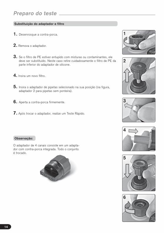
1. Desenrosque a contra-porca.
2. Remova o adaptador.
3. Se o filtro de PE estiver entupido com misturas ou contaminantes, ele deve ser substituído. Neste caso retire cuidadosamente o filtro de PE da parte inferior do adaptador de silicone.
4. Insira um novo filtro.
5. Insira o adaptador de pipetas selecionado na sua posição (na figura, adaptador 2 para pipetas sem ponteira).
6. Aperta a contra-porca firmemente.
7. Após trocar o adaptador, realize um Teste Rápido.
Preparo do teste
Substituição do adaptador e filtro
1
2
3
4
5
6
O adaptador de 4 canais consiste em um adapta-dor com contra-porca integrada. Todo o conjunto é trocado.
Observação:
14
Po
rtu
gu
ês
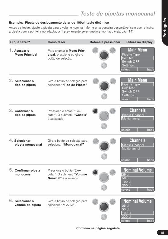
Teste de pipetas monocanal
Para chamar o Menu Prin-cipal, pressione ou gire o botão de seleção.
Gire o botão de seleção para selecionar “Tipo de Pipeta”
Pressione o botão “Exe-cutar”. O submenu “Canais” é acessado.
1. Acessar o Menu Principal
2. Selecionar o tipo de pipeta
3. Confirmar o tipo da pipeta
Gire o botão de seleção para selecionar “Monocanal”
Pressione o botão “Exe-cutar”. O submenu “Volume Nominal” é acessado
4. Selecionar pipeta monocanal
5. Confirmar pipeta monocanal
Main MenuPipette TypeSelf TestSwitch OFFSettings...select back
Main MenuPipette TypeSelf TestSwitch OFFSettings...select back
ChannelsSingle ChannelMultichannel
select back
Exemplo: Pipeta de deslocamento de ar de 100μl, teste dinâmico
Antes de testar, ajuste a pipeta para o volume nominal. Monte uma ponteira descartável sem uso, e insira a pipeta com a ponteira no adaptador 1 previamente selecionado e montado (veja pág. 14).
ChannelsSingle ChannelMultichannel
select back
Nominal Volume25 µl50 µl100 µl200 µlselect back
Gire o botão de seleção para selecionar “100 μl”.
6. Selecionar o volume da pipeta
Nominal Volume25 µl50 µl100 µl200 µlselect back
Continua na página seguinte
O que fazer? Como fazer Botões a pressionar Leitura no display
15

Teste de pipetas monocanal (cont.)
Pressione o botão “Iniciar/Executar”. O submenu “Iniciar” é acessado.
Pressione o botão “Iniciar/Executar”. O teste é inicia-do, e a pressão de teste é aplicada (em progresso...)
Antes do final do período de preparação, o sinal LED acende 1 vez vermelho e 1 vez verde, então a barra de progresso aparece e o siste-ma começa automaticamen-te a medição. Neste ponto o botão de pipetagem da pipe-ta deve ser pressionado por 2-3 vezes. O pistão deve re-tornar ao ponto inicial antes da medição terminar! A bar-ra de progresso indica o tem-po restante e o vácuo atingi-do no momento. O indicador LED pisca na cor laranja.
7. Confirmar o volume da pipeta
8. Iniciar o teste
Pressione o botão de pipetagem por 2 ou 3 vezes
ready
SC – 100 µl
start
Test
preparing...
restart back
Test
-121.21 hPa
restart back
4s
(o valor de pressão é apenas um exemplo)
PASS
start
SC – 100 µlQL: 0.04 hPa*ml/s
(a taxa de vazamento é apenas um exemplo)
Após o término do teste, o display indica a taxa de vaza-mento que foi determinada e se o sistema foi aprovado ou reprovado no teste.
O teste pode ser repetido ao pressionar o botão “Iniciar/Executar”.
FAIL
start
SC – 100 µlQL: 4.6 hPa*ml/s
(a taxa de vazamento é apenas um exemplo)
9. Finalizar o teste
O volume perdido pode ser aproximadamente determi-nado usando a tabela de correlação da pág. 29.
Verde
Vermelho
laranja
O que fazer? Como fazer Botões a pressionar Leitura no display
Observação:
16

Po
rtu
gu
ês
Teste de pipetas monocanal
Se o teste dinâmico indica a presença de vazamentos, tente localizar a fonte do vazamento com os seguintes testes:
1. Um teste estático deve ser realizado.
O botão de pipetagem não é pressionado e o pistão não se move. Se a pipeta agora está livre de vazamento isso indica que há arranhões no pistão.
2. O teste dinâmico deve ser realizado sem a ponteira.
O adaptador 2 dever utilizado neste caso. Se a pipeta agora está livre de vazamento, é possível que uma ponteira não adequada tenha sido utiliza-da.
No primeiro teste após ligar o instrumento, um volume relativamente maior deve ser bombeado, após o qual o instrumento tem tempo de estabilizar (re-laxar). Normalmente alterar entre pipetas grandes e pequenas leva a tempos maiores de teste pois a pressão de medição deve ser restaurada a cada vez.O tempo de medição para pipetas de 1000 μl é ,geralmente, de 5 segundos enquanto pode levar 20 segundos para pipetas de 10 ml.
As letras adicionadas após alguns volumes durante a seleção de volume indicam:
y = Amarelo (instrumento com ponteira amarela)
c = Ponteiras transparentes
n = Ponteira nano-cap
soft = Durante o teste de pipetas de 5ml e 10ml, o pistão pode não se mover completamente até a posição superior durante o teste dinâmico, pode permanecer preso no instrumento devido ao vácuo e fricção. Neste caso selecione os modos de teste “5 ml soft ou 10 ml soft”.
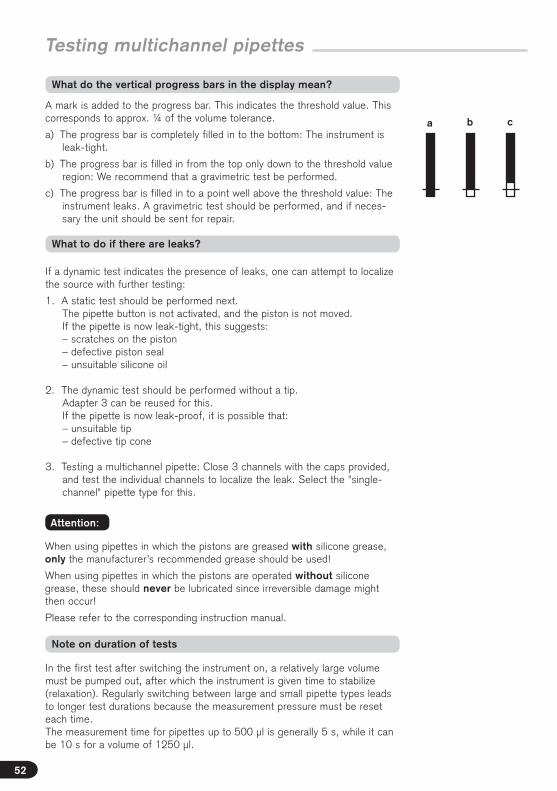
Uma marca está adicionada à barra de progresso. Ela indica o valor limite. O valor corresponde a aproximadamente ¼ da tolerância de volume de acordo com a ISSO 8655-2.
a) A barra de progresso está completamente preenchida, até a base: A pipeta é hermética.
b) A barra está completa de cima até a marca de valor limite: recomendamos realizar um ensaio gravimétrico.
c) A barra é preenchida até um ponto acima do valor limite: O instrumento tem vazamento. Um teste gravimétrico deve ser realizado e, se necessá-rio, a unidade deve ser enviada para reparo.
O que fazer se há vazamentos?
O que a barra de progresso vertical significa?
a b c
O que as letras após os volumes indicam?
Observações sobre a duração dos testes
17
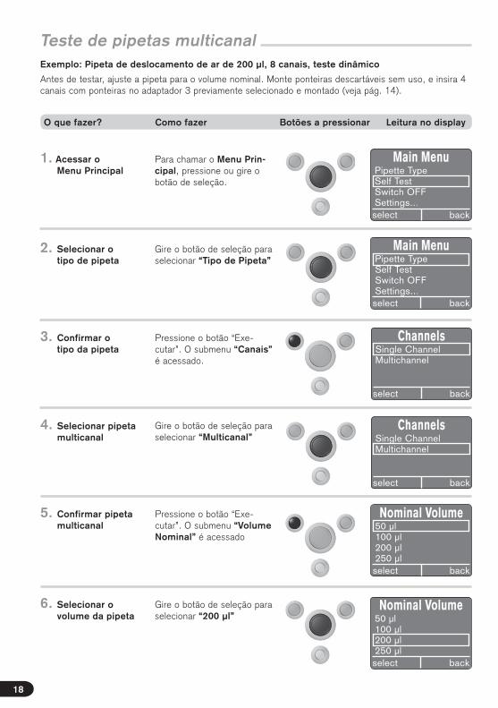
Para chamar o Menu Prin-cipal, pressione ou gire o botão de seleção.
Gire o botão de seleção para selecionar “Tipo de Pipeta”
Pressione o botão “Exe-cutar”. O submenu “Canais” é acessado.
1. Acessar o Menu Principal
2. Selecionar o tipo de pipeta
3. Confirmar o tipo da pipeta
Gire o botão de seleção para selecionar “Multicanal”
Pressione o botão “Exe-cutar”. O submenu “Volume Nominal” é acessado
4. Selecionar pipeta multicanal
5. Confirmar pipeta multicanal
Main MenuPipette TypeSelf TestSwitch OFFSettings...select back
Main MenuPipette TypeSelf TestSwitch OFFSettings...select back
ChannelsSingle ChannelMultichannel
select back
ChannelsSingle ChannelMultichannel
select back
Nominal Volume50 µl100 µl200 µl250 µlselect back
Gire o botão de seleção para selecionar “200 μl”
6. Selecionar o volume da pipeta
Nominal Volume50 µl100 µl200 µl250 µlselect back
Teste de pipetas multicanalExemplo: Pipeta de deslocamento de ar de 200 μl, 8 canais, teste dinâmico
Antes de testar, ajuste a pipeta para o volume nominal. Monte ponteiras descartáveis sem uso, e insira 4 canais com ponteiras no adaptador 3 previamente selecionado e montado (veja pág. 14).
O que fazer? Como fazer Botões a pressionar Leitura no display
18

Po
rtu
gu
ês
ready
MC – 200 µl
start
Test
preparing...
restart back
Test
-121.21 hPa
restart back
4s
(o valor de pressão é apenas um exemplo)
PASS
start
MC – 200 µlQL: 0.04 hPa*ml/s
Após o término do teste, o display indica a taxa de vaza-mento que foi determinada e se o sistema foi aprovado ou reprovado no teste.
O teste pode ser repetido ao pressionar o botão “Iniciar/Executar”.
FAIL
start
MC – 200 µlQL: 4.6 hPa*ml/s
9. Finalizar o teste
Teste de pipetas multicanal
Verde
VermelhoO volume perdido pode ser aproximadamente determi-nado usando a tabela de correlação da pág. 29.
Pressione o botão “Iniciar/Executar”. O submenu “Iniciar” é acessado.
Pressione o botão “Iniciar/Executar”. O teste é iniciado, e a pressão de teste é aplicada (em progresso...)
Antes do final do período de preparação, o sinal LED acende 1 vez vermelho e 1 vez verde, então a barra de progresso aparece e o siste-ma começa automaticamen-te a medição. Neste ponto o botão de pipetagem da pipe-ta deve ser pressionado por 2-3 vezes. O pistão deve re-tornar ao ponto inicial antes da medição terminar! A bar-ra de progresso indica o tem-po restante e o vácuo atingi-do no momento. O indicador LED pisca na cor laranja.
7. Confirmar o volume da pipeta
8. Iniciar o teste
Pressione o botão de pipetagem por 2 ou 3 vezes
laranja
(a taxa de vazamento é apenas um exemplo)
(a taxa de vazamento é apenas um exemplo)
O que fazer? Como fazer Botões a pressionar Leitura no display
Observação:
19

Uma marca está adicionada à barra de progresso. Ela indica o valor limite. O valor corresponde a aproximadamente ¼ da tolerância de volume.
a) A barra de progresso está completamente preenchida, até a base: A pipe-ta é hermética.
b) A barra está completa de cima até a marca de valor limite: recomendamos realizar um ensaio gravimétrico.
c) A barra é preenchida até um ponto acima do valor limite: O instrumento tem vazamento. Um teste gravimétrico deve ser realizado e, se necessá-rio, a unidade deve ser enviada para reparo.
O que fazer se há vazamentos?
O que a barra de progresso vertical significa?
a b c
Teste de pipetas multicanal
No primeiro teste após ligar o instrumento, um volume relativamente maior deve ser bombeado, após o qual o instrumento tem tempo de estabilizar (re-laxar). Normalmente alterar entre pipetas grandes e pequenas leva a tempos maiores de teste pois a pressão de medição deve ser restaurada a cada vez.O tempo de medição para pipetas de até 500 μl é ,geralmente, de 5 segun-dos enquanto pode levar 10 segundos para volumes de 1250 μl.
Observações sobre a duração dos testes
20
Se o teste dinâmico indica a presença de vazamentos, tente localizar a fonte do vazamento com os seguintes testes:
1. Um teste estático deve ser realizado. O botão de pipetagem não é pressionado e o pistão não se move. Ist das Gerät jetzt dicht, kann das ein Hinweis sein auf: – Kratzer am Kolben – defekte Kolbendichtung – ungeeignetes Silikonfett
2. O teste dinâmico deve ser realizado sem a ponteira. O adaptador 3 pode ser utilizado para isso. Se a pipeta agora está livre de vazamento, können die möglichen Ursachen sein: – ungeeignete Spitzen – defekter Spitzenaufnahmekonus
3. Bei Prüfung einer Mehrkanalpipette: Feche 3 canais com os pinos fornecidos e teste os canais individualmente para localizar o vazamento. Selecione o tipo de pipeta “Monocanal” para isso.
Bei Verwendung von Pipetten, deren Kolben mit Silikonfett eingefettet sind, darf ausschließlich das vom Hersteller empfohlene Fett verwendet werden!
Bei Verwendung von Pipetten, deren Kolben ohne Silikonfett betrieben werden, dürfen diese niemals eingefettet werden, da irreversible Schäden entstehen können!
Bitte Hinweise in der entsprechenden Gebrauchsanleitung beachten.
Achtung:
Po
rtu
gu
ês
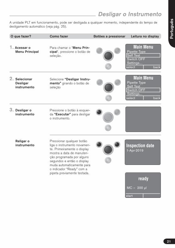
Desligar o InstrumentoA unidade PLT em funcionamento, pode ser desligada a qualquer momento, independente do tempo de desligamento automático (veja pág. 25).
Para chamar o 'Menu Prin-cipal', pressione o botão de seleção.
Selecione “Desligar Instru-mento” girando o botão de seleção
Pressione o botão à esquer-da “Executar” para desligar o instrumento.
1. Acessar o Menu Principal
2. Selecionar Desligar instrumento
3. Desligar o instrumento
Pressionar qualquer botão liga o instrumento novamen-te. Primeiramente o display mostra a data de manuten-ção programada por alguns segundos e então o display muda automaticamente para o indicador “Ready” com a pipeta previamente testada.
4. Religar o instrumento
Main MenuPipette TypeSelf TestSwitch OFFSettings...select back
Main MenuPipette TypeSelf TestSwitch OFFSettings...select back
ready
MC – 200 µl
start
Inspection date1-Apr-2019
O que fazer? Como fazer Botões a pressionar Leitura no display
21

Seleção do idioma Ajustes
No submenu “Settings”(Configuração), os seguintes subitens podem ser selecionados: Idioma, contraste, data de manutenção, tempo de desligamento, unidades de pressão e padrões de fábrica.
Chame o "Menu Principal", ao pressionar o botão de seleção e gire para selecio-nar “Settings”.
Pressione o botão “Exe-cutar”. O submenu “Settings” é selecionado.
1. Selecione “Settings” no Menu Principal
2. Confirmar a seleção
Gire o botão de seleção para selecionar “Language” (Idioma).
Pressione o botão “Exe-cutar”. O Menu “Language” (Idioma) é acessado. Gire o botão de seleção para selecionar o idioma.
3. Selecionar o idioma
4. Acessando o Menu de idiomas
Main MenuPipette TypeSelf TestSwitch OFFSettings...select back
Pressione o botão “Exe-cutar”. O menu “Settings” retorna e o idioma é sele-cionado.
O botão “Retornar” leva ao Menu Principal.
5. Confirmar o idioma
SettingsLanguageContrastInspection dateAuto-Power-Off Timeselect back
SettingsLanguageContrastInspection dateAuto-Power-Off Timeselect back
LanguageDeutschEnglishEspañol
o.k. back
SettingsLanguageContrastInspection dateAuto-Power-Off Timeselect back
O que fazer? Como fazer Botões a pressionar Leitura no display
22
+–
Po
rtu
gu
ês
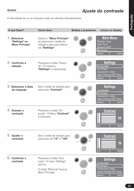
Ajuste do contraste
Chame o "Menu Principal", ao pressionar o botão de seleção e gire para selecio-nar “Settings”.
Pressione o botão “Execu-tar”. O submenu “Settings” é selecionado.
1. Selecione “Settings” no Menu Principal
2. Confirmar a seleção
Gire o botão de seleção para selecionar “Contrast”.
Pressione o botão “Ex-ecutar”. O Menu “Contrast” é acessado.
3. Selecionar a Data de Inspeção
4. Acessar o contraste
Main MenuPipette TypeSelf TestSwitch OFFSettings...select back
Pressione o botão “Exe-cutar”. O menu “Settings” retorna.
O botão “Retornar” leva ao Menu Principal.
6. Confirmar o contraste
SettingsLanguageContrastInspection dateAuto-Power-Off Timeselect back
SettingsLanguageContrastInspection dateAuto-Power-Off Timeselect back
Ajustes
SettingsLanguageContrastInspection dateAuto-Power-Off Timeselect back
Contrast
o.k. back
50
Gire o botão de seleção para selecionar de “10” a “100”.
5. Ajustar o contraste
Contrast
o.k. back
76
A intensidade da cor do indicador pode ser alterada interativamente.
O que fazer? Como fazer Botões a pressionar Leitura no display
23
+–
Chame o "Menu Principal", ao pressionar o botão de seleção e gire para selecio-nar “Settings”.
Pressione o botão “Exe-cutar”. O submenu “Set-tings” é selecionado.
1. Selecione “Settings” no Menu Principal
2. Confirmar a seleção
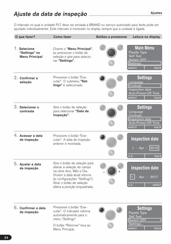
Gire o botão de seleção para selecionar “Data de Inspeção”.
Pressione o botão “Exe-cutar”. A data de inspeção anterior é mostrada.
3. Selecionar o contraste
4. Acessar a data de inspeção
Main MenuPipette TypeSelf TestSwitch OFFSettings...select back
Gire o botão de seleção para alterar a seleção do campo na série Ano, Mês e Dia. (Inserir a data atual retorna às configurações “Settings”). Girar o botão de seleção altera a posição enquadrada.
5. Ajustar a data de inspeção
SettingsLanguageContrastInspection dateAuto-Power-Off Timeselect back
SettingsLanguageContrastInspection dateAuto-Power-Off Timeselect back
Ajuste da data de inspeção Ajustes
i.O. zurück
Inspection date
1 - Apr - 2016
o.k. back
SettingsPipette TypeSelf TestSwitch OFFSettings...select back
6. Confirmar a data de inspeção
Pressione o botão “Exe-cutar”. O indicador retorna automaticamente para o menu “Settings”
O botão “Retornar” leva ao Menu Principal.
Inspection date
1 - Apr - 2017
o.k. select
O intervalo no qual a unidade PLT deve ser enviada à BRAND ou serviço autorizado para teste pode ser ajustado individualmente. Este intervalo é mostrado no display sempre que a unidade é ligada.
O que fazer? Como fazer Botões a pressionar Leitura no display
24

+–
Po
rtu
gu
ês
Ajuste do tempo de desligamento “Auto-Power-Off”
Chame o "Menu Principal", ao pressionar o botão de seleção e gire para selecio-nar “Settings”.
Pressione o botão “Execu-tar”. O submenu “Settings” é selecionado.
1. Selecione “Settings” no Menu Principal
2. Confirmar a seleção
Gire o botão de seleção para selecionar “Auto-Power-Off”.
Pressione o botão “Exe-cutar”. O tempo de desliga-mento anterior é mostrada.
3. Selecionar o auto-power-off
4. Acessando o auto-power-off
Main MenuPipette TypeSelf TestSwitch OFFSettings...select back
SettingsLanguageContrastInspection dateAuto-Power-Off Timeselect back
SettingsContrastInspection dateAuto-Power-Off TimePressure Unitselect back
i.O. zurück
Auto-Power-OffTime
o.k. back
O tempo de desligamento automático pode ser ajusta-do de “OFF” a 30 min..
5. Ajustar o tempo de desligamento automático
i.O. zurücko.k. back
6. Confirmar o tem- po de desligamen- to automático
Pressione o botão “Ex-ecutar”. O indicador retorna automaticamente para o menu “Settings”
O botão “Retornar” leva ao Menu Principal.
SettingsContrastInspection dateAuto-Power-Off TimePressure Unitselect back
O tempo de desligamento automático “ato-power-off” da unidade PLT pode ser ajustado individualmente em minutos de “OFF” a 30 minutos.
O que fazer? Como fazer Botões a pressionar Leitura no display
25
Auto-Power-OffTime
15 min

Ajuste da unidade de pressão Ajustes
Chame o "Menu Principal", ao pressionar o botão de seleção e gire para selecio-nar “Settings”.
Pressione o botão “Exe-cutar”. O submenu “Set-tings” é selecionado.
1. Selecione “Set- tings” no Menu Principal
2. Confirmar a seleção
Gire o botão de seleção para selecionar “Pressure Unit” (unidade de pressão).
Pressione o botão “Exe-cutar”. A unidade de pressão atual é indicada.
3. Selecionar uni-dade de pressão
4. Acessando uni-dade de pressão
Main MenuPipette TypeSelf TestSwitch OFFSettings...select back
SettingsInspection dateAuto-Power-Off TimePressure UnitFactory Settingsselect back
i.O. zurück
Pressure Unit
hPa
o.k. back
Gire o botão de seleção para ajustar a unidade de pressão em hPa, mbar, ou Torr.
5. Ajustar a unidade de pressão
6. Confirmar a uni-dade de pressão
Pressione o botão “Exe-cutar”. O indicador retorna automaticamente para o menu “Settings”
O botão “Retornar” leva ao Menu Principal.
SettingsContrastInspection dateAuto-Power-Off TimePressure Unitselect back
i.O. zurück
Pressure Unite
mbar
o.k. back
SettingsInspection dateAuto-Power-Off TimePressure UnitFactory Settingsselect back
O que fazer? Como fazer Botões a pressionar Leitura no display
26

Po
rtu
gu
ês
Configurações de fábricaAjustes
Chame o "Menu Principal", ao pressionar o botão de seleção e gire para selecio-nar “Settings”.
Pressione o botão “Exe-cutar”. O submenu “Set-tings” é selecionado.
1. Selecione “Set-tings” no Menu Principal
2. Confirmar a seleção
Gire o botão de seleção para selecionar “Factory Settings” (Configurações de Fábrica).
Pressione o botão “Ex-ecutar”. O comando de confirmação aparece.
3. Selecionar Configurações de Fábrica
4. Acessando Configurações de Fábrica
Main MenuPipette TypeSelf TestSwitch OFFSettings...select back
i.O. zurück
Factory Settings
please confirm!
o.k. back
5. Confirmar as Configurações de Fábrica
Pressione o botão “Ex-ecutar”. O indicador retorna para a seleção de idioma em “Inglês”.
SettingsInspection dateAuto-Power-Off TimePressure UnitFactory Settingsselect back
SettingsInspection dateAuto-Power-Off TimePressure UnitFactory Settingsselect back
LanguageDeutschEnglishEspanol
o.k.
SettingsInspection dateAuto-Power-Off TimePressure UnitFactory Settingsselect back
Após selecionar e confirmar o idioma, o indicador retorna automaticamente para o menu “Settings” (configura-ções).
O botão “Retornar” leva ao Menu Principal.
O que fazer? Como fazer Botões a pressionar Leitura no display
27
Atualização de Firmware
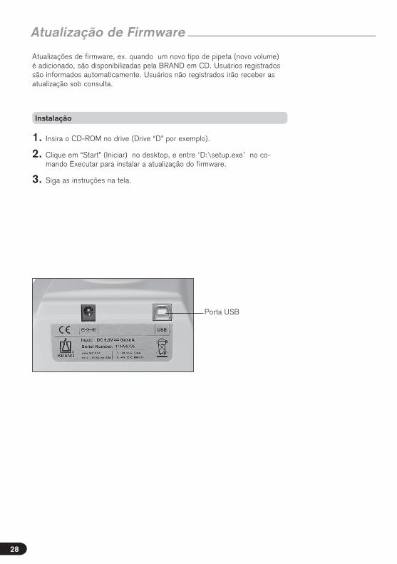
Instalação
1. Insira o CD-ROM no drive (Drive “D” por exemplo).
2. Clique em “Start” (Iniciar) no desktop, e entre ‘D:\setup.exe’ no co-mando Executar para instalar a atualização do firmware.
3. Siga as instruções na tela.
Atualizações de firmware, ex. quando um novo tipo de pipeta (novo volume) é adicionado, são disponibilizadas pela BRAND em CD. Usuários registrados são informados automaticamente. Usuários não registrados irão receber as atualização sob consulta.
Porta USB
28
Po
rtu
gu
ês
Tabela de Correlação
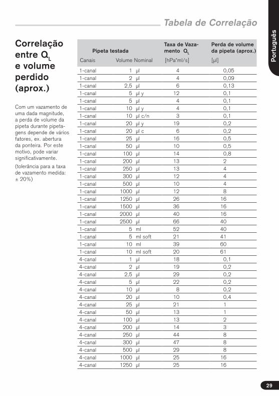
Correlação entre QL e volume perdido (aprox.)
Pipeta testadaTaxa de Vaza-mento QL
Perda de volume da pipeta (aprox.)
Canais Volume Nominal [hPa*ml/s] [μl]
1-canal 1 μl 4 0,051-canal 2 μl 4 0,091-canal 2,5 μl 6 0,131-canal 5 μl y 12 0,11-canal 5 μl 4 0,11-canal 10 μl y 4 0,11-canal 10 μl c/n 3 0,11-canal 20 μl y 19 0,21-canal 20 μl c 6 0,21-canal 25 μl 16 0,51-canal 50 μl 10 0,51-canal 100 μl 14 0,81-canal 200 μl 13 21-canal 250 μl 13 41-canal 300 μl 12 41-canal 500 μl 10 41-canal 1000 μl 12 81-canal 1250 μl 26 161-canal 1500 μl 36 161-canal 2000 μl 40 161-canal 2500 μl 66 401-canal 5 ml 52 401-canal 5 ml soft 21 411-canal 10 ml 39 601-canal 10 ml soft 20 614-canal 1 μl 18 0,14-canal 2 μl 19 0,24-canal 2,5 μl 29 0,24-canal 5 μl 22 0,24-canal 10 μl 8 0,24-canal 20 μl 10 0,44-canal 25 μl 21 14-canal 50 μl 13 14-canal 100 μl 13 24-canal 200 μl 14 34-canal 250 μl 44 84-canal 300 μl 47 84-canal 500 μl 29 84-canal 1000 μl 25 164-canal 1250 μl 25 16
Com um vazamento de uma dada magnitude, a perda de volume da pipeta durante pipeta-gens depende de vários fatores, ex. abertura da ponteira. Por este motivo, pode variar significativamente.
(tolerância para a taxa de vazamento medida: ± 20%)
29
Informações de Pedido · Acess. · Peças de Reposição
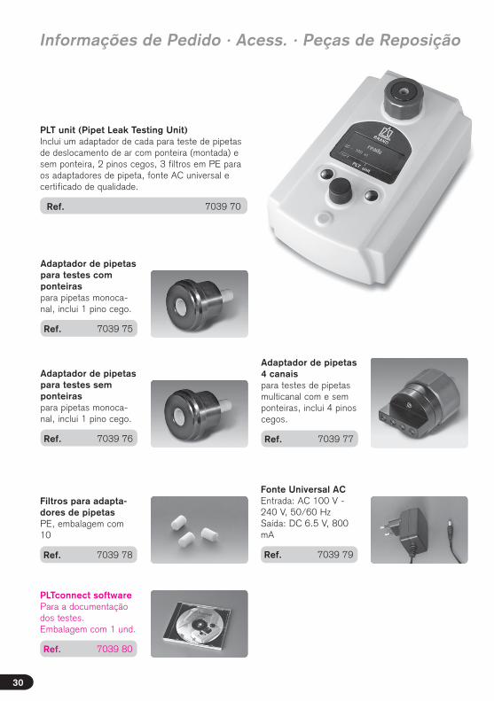
PLT unit (Pipet Leak Testing Unit) Inclui um adaptador de cada para teste de pipetas de deslocamento de ar com ponteira (montada) e sem ponteira, 2 pinos cegos, 3 filtros em PE para os adaptadores de pipeta, fonte AC universal e certificado de qualidade.
Ref. 7039 70
Adaptador de pipetas para testes com ponteiras para pipetas monoca-nal, inclui 1 pino cego.
Ref. 7039 75
Adaptador de pipetas para testes sem ponteiras para pipetas monoca-nal, inclui 1 pino cego.
Ref. 7039 76
Adaptador de pipetas 4 canais para testes de pipetas multicanal com e sem ponteiras, inclui 4 pinos cegos.
Ref. 7039 77
Filtros para adapta-dores de pipetas PE, embalagem com 10
Ref. 7039 78
Fonte Universal ACEntrada: AC 100 V - 240 V, 50/60 HzSaída: DC 6.5 V, 800 mA
Ref. 7039 79
30
PLTconnect software Para a documentação dos testes. Embalagem com 1 und.
Ref. 7039 80
Po
rtu
gu
ês
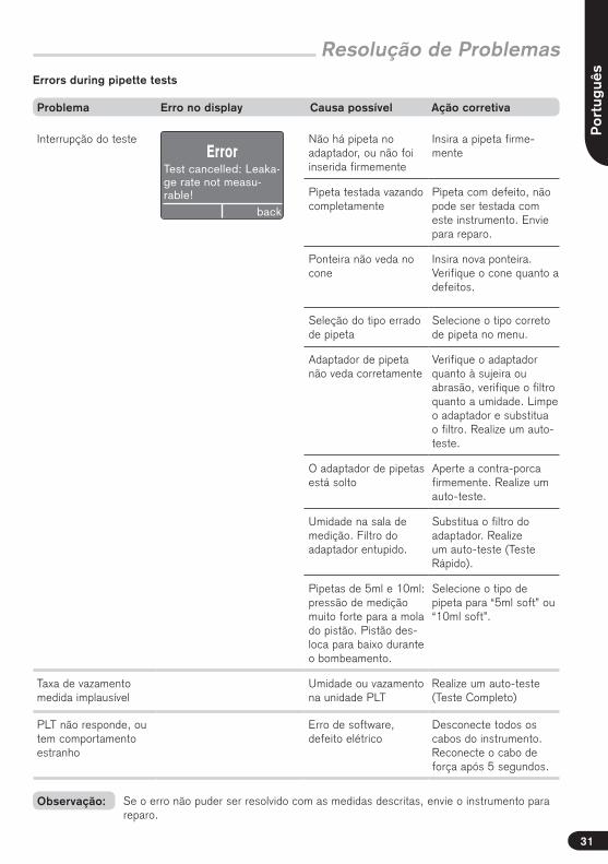
Interrupção do teste Não há pipeta no adaptador, ou não foi inserida firmemente
Insira a pipeta firme-mente
Pipeta testada vazando completamente
Pipeta com defeito, não pode ser testada com este instrumento. Envie para reparo.
Ponteira não veda no cone
Insira nova ponteira. Verifique o cone quanto a defeitos.
Seleção do tipo errado de pipeta
Selecione o tipo correto de pipeta no menu.
Adaptador de pipeta não veda corretamente
Verifique o adaptador quanto à sujeira ou abrasão, verifique o filtro quanto a umidade. Limpe o adaptador e substitua o filtro. Realize um auto-teste.
O adaptador de pipetas está solto
Aperte a contra-porca firmemente. Realize um auto-teste.
Umidade na sala de medição. Filtro do adaptador entupido.
Substitua o filtro do adaptador. Realize um auto-teste (Teste Rápido).
Pipetas de 5ml e 10ml: pressão de medição muito forte para a mola do pistão. Pistão des-loca para baixo durante o bombeamento.
Selecione o tipo de pipeta para “5ml soft” ou “10ml soft”.
Taxa de vazamento medida implausível
Umidade ou vazamento na unidade PLT
Realize um auto-teste (Teste Completo)
PLT não responde, ou tem comportamento estranho
Erro de software, defeito elétrico
Desconecte todos os cabos do instrumento. Reconecte o cabo de força após 5 segundos.
Resolução de Problemas
Problema Erro no display Causa possível Ação corretiva
Informações de Pedido · Acess. · Peças de Reposição
ErrorTest cancelled: Leaka-ge rate not measu-rable!
back
Errors during pipette tests
Se o erro não puder ser resolvido com as medidas descritas, envie o instrumento para reparo.
Observação:
31
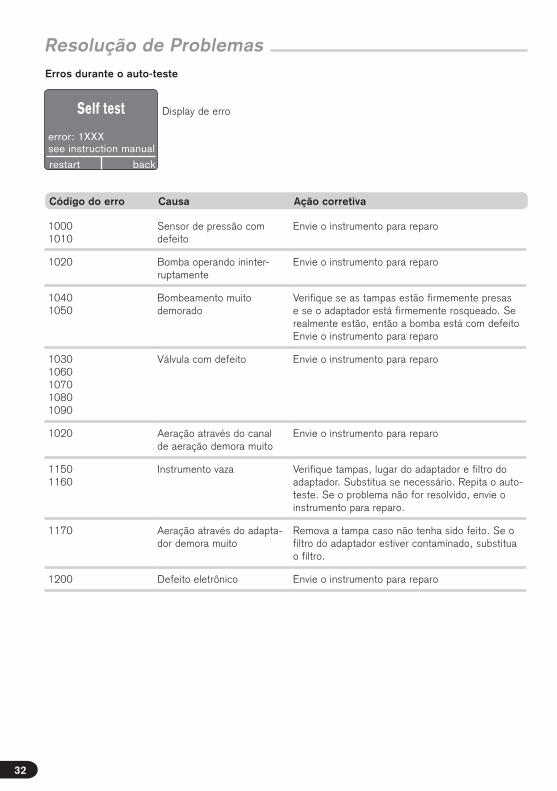
Resolução de Problemas
10001010
Sensor de pressão com defeito
Envie o instrumento para reparo
1020 Bomba operando ininter-ruptamente
Envie o instrumento para reparo
10401050
Bombeamento muito demorado
Verifique se as tampas estão firmemente presas e se o adaptador está firmemente rosqueado. Se realmente estão, então a bomba está com defeitoEnvie o instrumento para reparo
10301060107010801090
Válvula com defeito Envie o instrumento para reparo
1020 Aeração através do canal de aeração demora muito
Envie o instrumento para reparo
11501160
Instrumento vaza Verifique tampas, lugar do adaptador e filtro do adaptador. Substitua se necessário. Repita o auto-teste. Se o problema não for resolvido, envie o instrumento para reparo.
1170 Aeração através do adapta-dor demora muito
Remova a tampa caso não tenha sido feito. Se o filtro do adaptador estiver contaminado, substitua o filtro.
1200 Defeito eletrônico Envie o instrumento para reparo
Código do erro Causa Ação corretiva
Self test
error: 1XXXsee instruction manual
backrestart
Erros durante o auto-teste
Display de erro
32
Po
rtu
gu
ês
33
Reparos · Endereços de contato
– Limpe e descontamine o instrumento cuidadosamente.
– É muito importante sempre incluir uma descrição exata do tipo de problema e dos meios utilizados. Se a informação sobre os meios estiver faltando, o instru-mento não pode ser reparado.
– O transporte deve ser realizado por conta e risco do cliente.
Fora dos EUA e Canada:
– Preencha a “Declaração de Ausência de Riscos para a Saúde” e envie o instru-mento para o fabricante ou fornecedor. Solicite o modelo ao seu fornecedor ou fabricante. O modelo também se encontra na página www.brand.de para download.
Nos EUA e Canada:
– Contate a Brand Tech Scientific, Inc. e obtenha a autorização para retorno antes de enviar o instrumento para serviço.
– Retorne somente instrumentos limpos e descontaminados, com o Número de Autorização para Retorno permanentemente visível do lado de fora da embala-gem, para o endereço fornecido juntamente com o Número de Autorização para Retorno.
BRAND GMBH + CO KGOtto-Schott-Straße 2597877 Wertheim (Germany)
Tel.: +49 9342 808-0Fax: +49 9342 808-98000E-Mail: [email protected]
EUA e Canadá:BrandTech® Scientific, Inc.11 Bokum RoadEssex, CT 06426-1506 (USA)
Tel.: +1-860-767 2562Fax: +1-860-767 2563www.brandtech.com
India:BRAND Scientific Equipment Pvt. Ltd. 303, 3rd Floor, ‘C‘ Wing, DelphiHiranandani Business Park, PowaiMumbai - 400 076 (India)
Tel.: +91 22 42957790 Fax: +91 22 42957791 E-Mail: [email protected] www.brand.co.in
China:BRAND (Shanghai) Trading Co., Ltd. Guangqi Culture Plaza Room 506, Building B No. 2899, Xietu Road Shanghai 200030 (P.R. China)
Tel.: +86 21 6422 2318Fax: +86 21 6422 2268 E-Mail: [email protected]
Endereços de contato
Retorno para reparo
Importante! O transporte de produtos perigosos sem permissão é violação de lei federal.
Sujeito à modificações técnicas sem aviso prévio. Salvo erro ou omissão.
Descarte
O símbolo anexo significa que baterias/pilhas e instrumentos eletrônicos devem ser eliminados separadamente dos resíduos domésticos (resíduo municipal) no final das suas vidas úteis.
- De acordo com a Diretiva 2002/96/EC do Parlamento Europeu e do Conselho para Resíduos de Equipamentos Elétricos e Eletrônicos (WEEE) de 27 de janeiro de 2003. Equipamentos eletrônicos requerem eliminação especial de acordo com os regulamentos nacionais relevantes.
34
Não nos responsabilizamos por consequências causadas pelo uso impróprio, uso, manutenção, operação e reparos não autorizados do instrumento ou consequências do desgaste normal, especialmente de peças suscetíveis a desgaste como pistões, selos, válvulas e quebra de vidro, assim como do descumprimento das instruções contidas neste manual. Não nos responsabi-lizamos por danos resultantes de qualquer ação não descritas no manual de operações ou se peças não originais tenham sido utilizadas.
EUA e Canadá:Para informações sobre garantia, por favor veja www.brandtech.com.
Garantia
Eng
lish
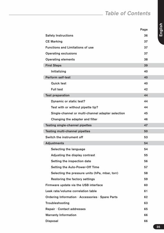
Table of Contents
Page
Safety Instructions 36
CE Marking 37
Functions and Limitations of use 37
Operating exclusions 37
Operating elements 38
First Steps 39
Initializing 40
Perform self-test 40
Quick test 40
Full test 42
Test preparation 44
Dynamic or static test? 44
Test with or without pipette tip? 44
Single-channel or multi-channel adapter selection 45
Changing the adapter and filter 46
Testing single-channel pipettes 47
Testing multi-channel pipettes 50
Switch the instrument off 53
Adjustments 54
Selecting the language 54
Adjusting the display contrast 55
Setting the inspection date 56
Setting the Auto-Power-Off Time 57
Selecting the pressure units (hPa, mbar, torr) 58
Restoring the factory settings 59
Firmware update via the USB interface 60
Leak rate/volume correlation table 61
Ordering Information · Accessories · Spare Parts 62
Troubleshooting 63
Repair · Contact addresses 65
Warranty Information 66
Disposal 66
35

Please read the following carefully!
This instrument may sometimes be used with hazardous materials, operations, and equipment. It is beyond the scope of this manual to address all of the potential safety risks associated with its use in such applica-tions. It is the responsibility of the user of this instrument to consult and establish appropriate safety and health practices and determine the applicability of regulatory limitations prior to use.
Safety Instructions
!
1. Every user must read and understand this operating manual before operation.
2. Follow general instructions for hazard preven-tion and safety instructions; e.g., wear protec-tive clothing, eye protection and gloves.
When working with infectious or other hazard-ous samples, all appropriate regulations and precautions must be followed.
3. Never use the instrument in an atmosphere with a danger of explosion.
4. The instrument should only be used for the leak testing of pipettes that operate on the air displacement principle. Observe operating exclusions (s. page 37)! If in doubt, contact the manufacturer or supplier.
5. Always use the instrument in such a way that neither the user nor any other person is endan-gered.
6. When testing air displacement pipettes with mounted tips, employ only unused tips.
7. Never use force on the instrument!
8. Use only original manufacturer's accessories and spare parts. Do not attempt to make any technical alterations.
9. Only authorized service personnel may repair or service the instrument.
10. Always check the instrument for visible dam-age before use. If there is a sign of a potential malfunction, immediately stop the test. Consult the 'Troubleshooting' section of this manual (see page 63), and contact the manufacturer if needed.
11. The AC adapter has to be protected against moisture and must be used only for this instru-ment.
36
Warning!
Improper use of the instrument (short-circuit, mechanical damage, over-heating etc.) may cause the explosion.

Eng
lish
Function and Limitations of use
The BRAND leak testing instrument is a differential pressure measuring instrument for determining the leak rate of an air-displacement pipette. Static and dynamic testing permit the localization of leaks. Dynamic testing is preferable.
Testing is possible both with tips (for testing the instrument/tip interface and the entire system) and without tips (for testing the instrument). The leak rate is directly related to the volume loss of a pipette.
The leak rate QL is a measure of the quantity of material (mass) that flows through a leak per unit time.
The instrument offers a rapid and simple test of leakage in air-displacement pipettes within the fol-lowing limitations:
– Operating temperature15 °C to 35 °C
– Rel. Humidity max 80%
– For use at elevations up to 2000 m above sea level
– Storage temperature 0 °C to 50 °C
Limitations of Use Operating Exclusions
Users themselves must check the suitability of the instrument for the intended application.
Do not use the instrument to aspirate liquids! Avoid aggressive vapors (corrosion hazard)! Further information available upon request.
Hollow vessels that are not specified for vacuum use should never be evacuated, since the vessel can burst!
The leak rate is the ratio of the pV value of a gas and the period of time during which the gas flows through the leak. The pV value is the product of the pressure and the volume of a certain quantity of a gas at the prevailing temperature. In ideal gases, the pV value at a given temperature is a measure of the quantity of material or the mass of the gas. The leak rate depends on the type of gas, absolute pressure, pressure difference, and temperature.
For the pipette test, hPa ml/s is a suitable unit for the leak rate QL. A leak rate of 1 hPa ml/s at an air pressure of 1000 hPa means a volume loss of 1 μl/s.
This sign certifies that the product meets the requirements of the EEC directive and has been tested according the specified test methods.
CE Marking
The leak tester cannot substitute for gravimetric testing for the monitoring of measuring instru-ments. The instrument should be used to check pipettes on a daily basis as a safeguard for the periods between calibrations.
AC adapter Specifications
Important!
PLT unit:
Input: DC 6.5 V= 800 mA
AC adapter:
Input: AC 100 V - 240 V, 50/60 Hz, 0,5 AOutput: DC 6,5 V= 800 mAProtection class: IP20
When the instrument is relocated to a new environ-ment or even during transport, significant changes in the temperature and atmospheric humidity can affect the measurements.To avoid error messages, the PLT unit must be allowed to acclimate in the testing laboratory for a period of 2 hours before use!
37
Note:
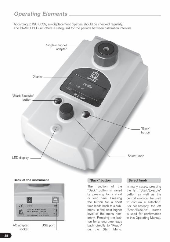
Operating Elements
According to ISO 8655, air-displacement pipettes should be checked regularly. The BRAND PLT unit offers a safeguard for the periods between calibration intervals.
Single-channel adapter
"Back" button
AC adapter socket
"Start/Execute" button
Select knobLED display
Display
USB port
Back of the instrument
The function of the "Back" button is varied by pressing for a short or long time. Pressing the button for a short time leads back to a sub-menu in the next higher level of the menu hier-archy. Pressing the but-ton for a long time leads back directly to "Ready" on the Start Menu.
"Back" button Select knob
In many cases, pressing the left "Start/Execute" button as well as the central knob can be used to confirm a selection. For consistency, the left "Start/Execute" button is used for confirmation in this Operating Manual.
38

Eng
lishIs everything in the package?
The package contains the PLT unit, one adapter each for testing air-displacement pipettes with tips (mounted) or without tips, 2 blind plugs, 3 replacement PE filters for the pipette adapter, an AC adapter, a quality certificate, and this Operating Manual.
First Steps
Use only the origi-nal AC adapter!
The instrument's AC adapter and AC adapter plug must be freely accessible, and separatable from the power grid at any time.
LanguageDeutschEnglishEspañol
o.k.
SettingsLanguageContrastInspection dateAuto-Power-Off Timeselect back
What to do? How to do it Keys to press Display readout
Connect the AC adapter to the socket in the back of the instrument, without pressing any buttons on the instrument.
After the AC adappter is connected, the display shows the software version number, the creation date, and the BRAND logo.
During initial start-up, the display brings up the "Lan-guage" indicator after 3 sec.
1. Connecting the AC adapter
The language is selected by turning the select knob.
2. Selecting the language
Press the left "OK" button.The "Settings" menu appears in the language selected.
The "Back" button leads to the Main Menu.
3. Confirming the language
LanguageDeutschEnglishEspañol
o.k.
After start-up, one can select either to perform the self-test (page 40) or directly begin a pipette test (page 44).
Powering on the instru-ment
Note:
39
V1.40.0113-Mar-2011
Firmware

The self-test determines if there are any leaks in the BRAND PLT unit. Two different tests are available. The Quick Test lasts only about 2 minutes, and should be performed on a daily basis. The Full Test lasts about 12 minutes. It includes the additional differentiated testing of the internal tanks, and should be performed on a weekly basis.
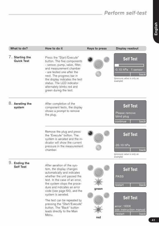
Perform self-test
Quick test
The Main Menu is called up by pressing or turning the select knob.
Set to "Self Test" by turning the select knob.
Press the "Execute" button. The "Self Test" submenu is called up. The last test to be performed appears enframed.
1. Calling up the Main Menu
2. Setting up the Self Test
3. Confirming the Self Test
Set to "Quick Test" by turn-ing the select knob.
Press the "Start/Execute" button.The "Start Menu" submenu is called up.
4. Selecting the Quick Test
5. Confirming the Quick Test
6. Seal the system
select back
Main MenuPipette TypeSelf TestSwitch OFFSettings...
Main MenuPipette TypeSelf TestSwitch OFFSettings...select back
Self TestQuick TestFull Test
select back
Self TestPlease insertblind plug
start back
Self TestQuick TestFull Test
select back
Press the provided blind plug firmly into the adapter (for the multi-channel adapter, seal all 4 chan-nels).
What to do? How to do it Keys to press Display readout
40
select back
Eng
lish
Press the "Start/Execute" button. The five components - sensor, pump, valve, filter, and measurement chamber - are tested one after the next. The progress bar in the display indicates the test status. The LED indicator alternately blinks red and green during the test.
After completion of the component tests, the display shows a prompt to remove the plug.
Remove the plug and press the "Execute" button. The system is aerated and the in-dicator will show the current pressure in the measurement chamber.
7. Starting the Quick Test
8. Aerating the system
After aeration of the sys-tem, the display changes automatically and indicates whether the unit passed the test. In the case of an error, the system stops the proce-dure and indicates an error code (see page 64), and the system is aerated.
The test can be repeated by pressing the "Start/Execute" button. The "Back" button leads directly to the Main Menu.
9. Ending the Self Test
Perform self-test
Self TestPlease removeblind plug
continue back
Self TestPASS
restart back
Self Test
-0.10 hPa 1:sensor
back
Self Test
-20.10 hPa
back
(pressure value is only an example)
(pressure value is only an example)
green
red
Self Test
error: 1XXXsee instruction manual
backrestart
What to do? How to do it Keys to press Display readout
41

–
The self test determines if there are any leaks in the BRAND PLT unit. Two different tests are available. The Quick Test lasts only about 2 minutes, and should be performed on a daily basis. The Full Test lasts about 12 minutes. It includes the additional differentiated testing of the internal tanks, and should be performed on a weekly basis.
Perform self test
Full test
The 'Main Menu' is called up by pressing or turning the select knob.
Set to 'Self Test' by turning the select knob.
Press the 'Execute' button. The 'Self Test' submenu is called up. The last test to be performed appears enframed.
1. Calling up the Main Menu
2. Setting up the Self Test
3. Confirming the Self Test
Set to 'Selecting the Full Test' by turning the select knob.
Press the 'Start/Execute' button.The 'Start Menu' submenu is called up.
Press the provided plug firmly into the adapter (for the multi-channel adapter, seal all 4 channels).
4. Selecting the Full Test
5. Confirming the Full Test
6. Seal the system
Main MenuPipette TypeSelf TestSwitch OFFSettings...select back
Main MenuPipette TypeSelf TestSwitch OFFSettings...select back
Self TestQuick TestFull Test
select back
Self TestPlease insertblind plug
start back
Self TestQuick TestFull Test
select back
What to do? How to do it Keys to press Display readout
42

Eng
lish
Press the 'Start/Execute' button.The six components - sen-sor, pump, valve, filter, mea-surement chamber, and the tanks - are tested one after the next. The progress bar in the display indicates the test status. The LED indicator alternately blinks red and green during the test.
After completion of the component tests, the display shows a prompt to remove the plug.
Remove the plug and press the 'Execute' button. The system is aerated and the indicator will show the cur-rent pressure.
7. Starting the Full Test
8. Aerating the system
After aeration of the sys-tem, the display changes automatically and indicates whether the unit passed the test. In the case of an error, the system stops the proce-dure and indicates an error code (see page 64), and the system is aerated.
The test can be repeated by pressing the 'Start/Execute' button. The 'Back' button leads directly to the Main Menu.
9. Ending the Self Test
Perform self-test
Self TestPlease removeblind plug
continue back
Self TestPASS
restart back
Self Test
-0.10 hPa 1:sensor
back
Self Test
-20.10 hPa
back
(pressure value is only an example)
(pressure value is only an example)
green
red
Self Test
error: 1XXXsee instruction manual
backrestart
What to do? How to do it Keys to press Display readout
43

Test preparation
Before the test, one must decide whether a dynamic or static test is to be performed.
With the dynamic test, in addition to the detection of static leaks, one can also determine whether a defective piston (contamination, scratches) has caused a leak.
During the measurement time, the pipette button must be pressed down completely and evenly 2-3 times. The associated piston movement allows errors to be recognized.The button stroke is accomplished relatively slowly with 5 ml and 10 ml pipettes.In the dynamic testing of pipettes, the piston should be in the upper position at the beginning, and should be brought back to that position at the end.
In the static test, by contrast, the pipette button is not pressed during the test procedure, i.e. the piston doesn't move. In power pipettes, one can posi-tion the piston in the uppermost location or at the 1st stop.A leak that occurs during the piston stroke can thus not be determined at this point.
We recommend that the dynamic test be performed.
Dynamic or static test?
The test can take place with or without the pipette tip.
We recommend that the test be performed with a mounted, unused tip so that the entire pipette system is tested.
When a leak has been identified, the test can be repeated without a tip to determine whether the leak arises from the tip cone/tip coupling region. The adapter must be changed (see page 46) to be able to perform the test without the tip.
The pipette should be held firmly during the test.
Test with or without pipette tip?
44

Eng
lish
To protect the instrument from moisture and contamination, a readily change-able PE filter is included in the bottom the silicone adapter.
1
2
3
Changing the adapter
A total of 3 adapters are available
Adapter 1: already premounted, for testing single-channel pipettes up to 10 ml with a mounted pipette tip
Adapter 2: included in the delivery, for testing single-channel pipettes without a pipette tip
Adapter 3: available separately (optional), for testing of multi-channel pipettes with or without a pipette tip, wherein all 4 channels are tested simultaneously. The 4-channel adapter can be used for 4-, 8- and 12-channel pipettes.
When a leak is detected, three channels can be closed with plugs. The leaking channel can be determined through subse-quent single-channel testing.
During multi-channel pipettes testing, the tips can be allowed to remain in the adapter when the instrument is disconnected. These can be removed simply by hand, or left inserted for the next test.
Test preparation
Testing of single- or multi-channel pipettes
Important!
45

1. Unscrewing the adapter lock nut.
2. Remove the pipette adapter.
3. If the PE filter is clogged with moisture or contaminants, it must be changed. In this case, carefully withdraw the PE filter from the bottom end of the silicone adapter.
4. Insert a new filter.
5. Insert the selected pipette adapter into the adapter housing (in the figure, Adapter 2 for pipettes without tips).
6. Screw the lock nut down firmly.
7. After changing the adapter, perform the Quick Test.
Test preparation
Changing the adapter and filter
1
2
3
4
5
6
The 4-channel adapter consists of an adapter with an integrated lock nut. The entire ensemble is exchanged.
Note:
46

Eng
lish
Testing single-channel pipettes
The 'Main Menu' is called up by pressing or turning the select knob.
Set to 'Pipette Type' by turning the select knob.
Press the 'Execute' button. The 'Channels' submenu is called up.
1. Calling up the Main Menu
2. Selecting the pipette type
3. Confirming the pipette type
Set to 'Single-Channel' by turning the select knob.
Press the 'Execute' button. The 'Nominal Volume' submenu is called up.
4. Selecting the single-channel pipette
5. Confirming the single-channel pipette
Main MenuPipette TypeSelf TestSwitch OFFSettings...select back
Main MenuPipette TypeSelf TestSwitch OFFSettings...select back
ChannelsSingle ChannelMultichannel
select back
Example: 100 μl Air-displacement pipette, dynamic test
Before testing set pipette to nominal volume. Mount a new, unused, disposable tip, and insert the pipette with the tip in the previously selected and attached Adapter 1 (see page 46).
ChannelsSingle ChannelMultichannel
select back
Nominal Volume25 µl50 µl100 µl200 µlselect back
'100 μl' is selected by turn-ing the select knob.
6. Selecting the pipette volume
Nominal Volume25 µl50 µl100 µl200 µlselect back
Continued on next page
What to do? How to do it Keys to press Display readout
47
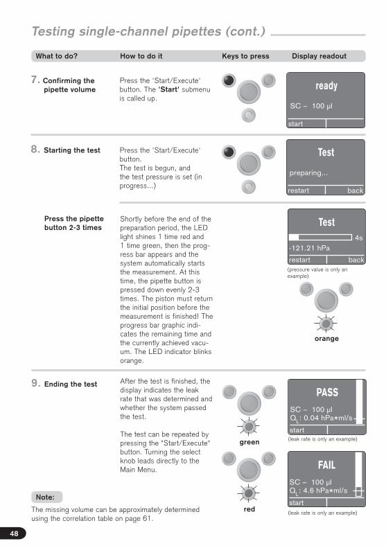
Testing single-channel pipettes (cont.)
Press the 'Start/Execute' button. The 'Start' submenu is called up.
Press the 'Start/Execute' button.The test is begun, and the test pressure is set (in progress...)
Shortly before the end of the preparation period, the LED light shines 1 time red and 1 time green, then the prog-ress bar appears and the system automatically starts the measurement. At this time, the pipette button is pressed down evenly 2-3 times. The piston must return the initial position before the measurement is finished! The progress bar graphic indi-cates the remaining time and the currently achieved vacu-um. The LED indicator blinks orange.
7. Confirming the pipette volume
8. Starting the test
Press the pipette button 2-3 times
ready
SC – 100 µl
start
Test
preparing...
restart back
Test
-121.21 hPa
restart back
4s
(pressure value is only an example)
PASS
start
SC – 100 µlQL: 0.04 hPa*ml/s
(leak rate is only an example)
After the test is finished, the display indicates the leak rate that was determined and whether the system passed the test.
The test can be repeated by pressing the "Start/Execute" button. Turning the select knob leads directly to the Main Menu. FAIL
start
SC – 100 µlQL: 4.6 hPa*ml/s
(leak rate is only an example)
9. Ending the test
The missing volume can be approximately determined using the correlation table on page 61.
green
red
orange
What to do? How to do it Keys to press Display readout
Note:
48

Eng
lish
Testing single-channel pipettes
If a dynamic test indicates the presence of leaks, one can attempt to localize the source with further testing:
1. A static test should be performed next.
The pipette button is not activated, and the piston is not moved. If the pipette is now leak-tight, this suggests there are scratches on the piston.
2. The dynamic test should be performed without a tip.
Adapter 2 must be used in this case. If the pipette is now leak-proof, it is possible that an unsuitable tip was used.
In the first test after switching the instrument on, a relatively large volume must be pumped out, after which the instrument is given time to stabilize (relaxation). Regularly switching between large and small pipette types leads to longer test durations because the measurement pressure must be reset each time.The measurement time for pipettes up to 1000 μl is generally 5 s, while it can be 20 s for 10 ml instruments.
The additional letters after some volumes during volume selection mean:
y = Yellow (instrument with yellow tips)
c = Clear tips
n = nano-cap tip
soft = During the testing of 5 ml and 10 ml pipettes, the piston might no longer move all the way back to top during the dynamic test, but might remain stuck in the instrument due to vacuum and friction. In this case, select the "5 ml soft or 10 ml soft" test mode.
A mark is added to the progress bar. This indicates the threshold value. This corresponds to approx. ¼ of the volume tolerance according to ISO 8655-2.
a) The progress bar is completely filled in to the bottom: The pipette is leak-tight.
b) The progress bar is filled in from the top only down to the threshold value region: We recommend that a gravimetric test be performed.
c) The progress bar is filled in to a point well above the threshold value: The pipette leaks. A gravimetric test should be performed, and if necessary the unit should be sent for repair.
What to do if there are leaks?
What do the vertical progress bars in the display mean?
a b c
What do the letters after some volumes mean?
Note on duration of tests
49

The 'Main Menu' is called up by pressing or turning the select knob.
Set to 'Pipette Type' by turning the select knob.
Press the 'Execute' button. The 'Channels' submenu is called up.
1. Calling up the Main Menu
2. Selecting the pipette type
3. Confirming the pipette type
Set to 'Multichannel' by turning the select knob.
Press the 'Execute' button. The 'Nominal Volume' submenu is called up.
4. Selecting the multichannel pipette
5. Confirming the multichannel pipette
Main MenuPipette TypeSelf TestSwitch OFFSettings...select back
Main MenuPipette TypeSelf TestSwitch OFFSettings...select back
ChannelsSingle ChannelMultichannel
select back
ChannelsSingle ChannelMultichannel
select back
Nominal Volume50 µl100 µl200 µl250 µlselect back
'200 μl' is selected by turn-ing the select knob.
6. Selecting the pipette volume
Nominal Volume50 µl100 µl200 µl250 µlselect back
Testing multichannel pipettesExample: 200 μl 8-channel air-displacement pipette, dynamic test
Before testing set pipette to nominal volume. Mount a new, unused, disposable tip, and insert four chan-nels with tips in the previously selected and attached Adapter 3 (see page 46).
What to do? How to do it Keys to press Display readout
50

Eng
lish
ready
MC – 200 µl
start
Test
preparing...
restart back
Test
-121.21 hPa
restart back
4s
(pressure value is only an example)
PASS
start
MC – 200 µlQL: 0.04 hPa*ml/s
After the test is finished, the display indicates the leak rate that was determined and whether the system passed the test.
The 'Start/Execute' button can be used to repeat the test, or the test can be continued with the next 4 channels.
Turning the select knob leads directly to the Main Menu.
FAIL
start
MC – 200 µlQL: 4.6 hPa*ml/s
9. Ending the test
Testing multichannel pipettes
green
redThe missing volume can be approximately determined using the correlation table on page 61.
Press the 'Start/Execute' button. The 'Start' submenu is called up.
Press the 'Start/Execute' button.The test is begun, and the test pressure is set (in progress...)
Shortly before the end of the preparation period, the LED light shines 1 time red and 1 time green, then the progress bar appears and the sys-tem automatically starts the measurement. At this time, the pipette button is pressed down evenly 2-3 times. The piston must return the initial position before the measure-ment is finished! The prog-ress bar graphic indicates the remaining time and the cur-rently achieved vacuum. The LED indicator blinks or-ange.
7. Confirming the pipette volume
8. Starting the test
Press the pipette button 2-3 times
orange
(leak rate is only an example)
(leak rate is only an example)
What to do? How to do it Keys to press Display readout
Note:
51
If a dynamic test indicates the presence of leaks, one can attempt to localize the source with further testing:
1. A static test should be performed next. The pipette button is not activated, and the piston is not moved. If the pipette is now leak-tight, this suggests: – scratches on the piston – defective piston seal – unsuitable silicone oil
2. The dynamic test should be performed without a tip. Adapter 3 can be reused for this. If the pipette is now leak-proof, it is possible that: – unsuitable tip – defective tip cone
3. Testing a multichannel pipette: Close 3 channels with the caps provided, and test the individual channels to localize the leak. Select the "single-channel" pipette type for this.
A mark is added to the progress bar. This indicates the threshold value. This corresponds to approx. ¼ of the volume tolerance.
a) The progress bar is completely filled in to the bottom: The instrument is leak-tight.
b) The progress bar is filled in from the top only down to the threshold value region: We recommend that a gravimetric test be performed.
c) The progress bar is filled in to a point well above the threshold value: The instrument leaks. A gravimetric test should be performed, and if neces-sary the unit should be sent for repair.
What to do if there are leaks?
What do the vertical progress bars in the display mean?
a b c
Testing multichannel pipettes
In the first test after switching the instrument on, a relatively large volume must be pumped out, after which the instrument is given time to stabilize (relaxation). Regularly switching between large and small pipette types leads to longer test durations because the measurement pressure must be reset each time.The measurement time for pipettes up to 500 μl is generally 5 s, while it can be 10 s for a volume of 1250 μl.
Note on duration of tests
52
When using pipettes in which the pistons are greased with silicone grease, only the manufacturer’s recommended grease should be used!
When using pipettes in which the pistons are operated without silicone grease, these should never be lubricated since irreversible damage might then occur!
Please refer to the corresponding instruction manual.
Attention:

Eng
lish
Switch the instrument offThe active PLT unit can be switched off at any time, independent of the shut-off time set (see page 57).
The 'Main Menu' is called up by pressing the select knob.
Set to 'Instrument OFF' by turning the select knob.
Press the left 'Execute' button to switch the instru-ment off.
1. Calling up the Main Menu
2. Selecting instrument off
3. Switch the instrument off
Pressing any button turns the instrument on again.At first, the display shows the scheduled maintenance date for a few seconds
Then it switches automati-cally to the 'Ready' indicator with the previously tested pipette.
4. Turning the instru- ment on again
Main MenuPipette TypeSelf TestSwitch OFFSettings...select back
Main MenuPipette TypeSelf TestSwitch OFFSettings...select back
ready
MC – 200 µl
start
Inspection date1-Apr-2019
What to do? How to do it Keys to press Display readout
53

Selecting the language Adjustments
In the 'Settings' submenu, the following subitems can be selected: Language, contrast, maintenance date, shut-off time, pressure units, and factory defaults.
Call up the 'Main Menu' by pressing the select knob, and turn it to select 'Set-tings'.
Press the 'Execute' button. The 'Settings' submenu is called up.
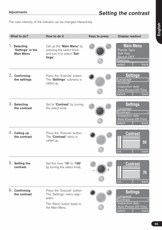
1. Selecting 'Settings' in the Main Menu
2. Confirming the settings
Set to 'Language' by turn-ing the select knob.
Press the 'Execute' button. The 'Language' menu is called up. The language is selected by turning the select knob.
3. Selecting the language
4. Calling up the Language Menu
Main MenuPipette TypeSelf TestSwitch OFFSettings...select back
Press the 'Execute' button. The 'Settings' menu appears in the language selected.
The 'Back' button leads to the Main Menu.
5. Confirming the language
SettingsLanguageContrastInspection dateAuto-Power-Off Timeselect back
SettingsLanguageContrastInspection dateAuto-Power-Off Timeselect back
LanguageDeutschEnglishEspañol
o.k. back
SettingsLanguageContrastInspection dateAuto-Power-Off Timeselect back
What to do? How to do it Keys to press Display readout
54
+–
Eng
lish
Setting the contrast
Call up the 'Main Menu' by pressing the select knob, and turn it to select 'Set-tings'.
Press the 'Execute' button. The 'Settings' submenu is called up.
1. Selecting 'Settings' in the Main Menu
2. Confirming the settings
Set to 'Contrast' by turning the select knob.
Press the 'Execute' button. The 'Contrast' menu is called up.
3. Selecting the contrast
4. Calling up the contrast
Main MenuPipette TypeSelf TestSwitch OFFSettings...select back
Press the 'Execute' button. The 'Settings' menu reap-pears.
The 'Back' button leads to the Main Menu.
6. Confirming the contrast
SettingsLanguageContrastInspection dateAuto-Power-Off Timeselect back
SettingsLanguageContrastInspection dateAuto-Power-Off Timeselect back
Adjustments
SettingsLanguageContrastInspection dateAuto-Power-Off Timeselect back
Contrast
o.k. back
50
Set this from '10' to '100' by turning the select knob.
5. Setting the contrast
Contrast
o.k. back
76
The color intensity of the indicator can be changed interactively.
What to do? How to do it Keys to press Display readout
55

+–
Call up the 'Main Menu' by pressing the select knob, and turn it to select 'Set-tings'.
Press the 'Execute' button. The 'Settings' submenu is called up.
1. Selecting 'Settings' in the Main Menu
2. Confirming the settings
Set to 'Inspection date' by turning the select knob.
Press the 'Execute' button. The previously set mainte-nance date is displayed.
3. Selecting the inspection date
4. Calling up the inspection date
Main MenuPipette TypeSelf TestSwitch OFFSettings...select back
Turning the select knob changes the selection field in the series Year, Month, and Day. (Pressing today's date leads back to 'Settings').Turning the select knob changes which position is enframed.
5. Setting the inspection date
SettingsLanguageContrastInspection dateAuto-Power-Off Timeselect back
SettingsLanguageContrastInspection dateAuto-Power-Off Timeselect back
Setting the Inspection date Adjustments
i.O. zurück
Inspection date
1 - Apr - 2016
o.k. back
SettingsPipette TypeSelf TestSwitch OFFSettings...select back
6. Confirming the inspection date
Press the 'Execute' button. The indicator returns auto-matically to the 'Settings' menu.
The 'Back' button leads to the Main Menu.
Inspection date
1 - Apr - 2017
o.k. select
The interval for when the PLT unit should be sent to BRAND or an authorized repair shop for testing can be set individually This interval is displayed each time the unit is switched on.
What to do? How to do it Keys to press Display readout
56
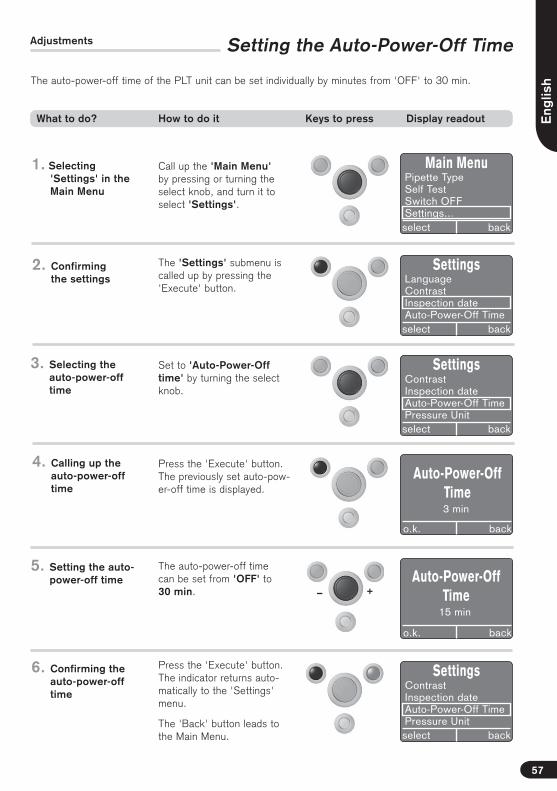
+–
Eng
lish
Setting the Auto-Power-Off TimeAdjustments
Call up the 'Main Menu' by pressing or turning the select knob, and turn it to select 'Settings'.
The 'Settings' submenu is called up by pressing the 'Execute' button.
1. Selecting 'Settings' in the Main Menu
2. Confirming the settings
Set to 'Auto-Power-Off time' by turning the select knob.
Press the 'Execute' button. The previously set auto-pow-er-off time is displayed.
3. Selecting the auto-power-off time
4. Calling up the auto-power-off time
Main MenuPipette TypeSelf TestSwitch OFFSettings...select back
SettingsLanguageContrastInspection dateAuto-Power-Off Timeselect back
SettingsContrastInspection dateAuto-Power-Off TimePressure Unitselect back
i.O. zurück
Auto-Power-OffTime3 min
o.k. back
The auto-power-off time can be set from 'OFF' to 30 min.
5. Setting the auto- power-off time
i.O. zurücko.k. back
6. Confirming the auto-power-off time
Press the 'Execute' button. The indicator returns auto-matically to the 'Settings' menu.
The 'Back' button leads to the Main Menu.
SettingsContrastInspection dateAuto-Power-Off TimePressure Unitselect back
The auto-power-off time of the PLT unit can be set individually by minutes from 'OFF' to 30 min.
What to do? How to do it Keys to press Display readout
57
Auto-Power-OffTime
15 min

Selecting the pressure unit Adjustments
Call up the 'Main Menu' by pressing or turning the select knob, and turn it to select 'Settings'.
Press the 'Execute' button. The 'Settings' submenu is called up.
1. Selecting 'Settings' in the Main Menu
2. Confirming the settings
Set to 'Pressure unit' by turning the select knob.
Press the left 'Execute' button. The currently set pressure units appear.
3. Selecting the pressure unit
4. Calling up the pressure units
Main MenuPipette TypeSelf TestSwitch OFFSettings...select back
SettingsInspection dateAuto-Power-Off TimePressure UnitFactory Settingsselect back
i.O. zurück
Pressure Unit
hPa
o.k. back
The pressure units can be set by turning the select knob to hPa, mbar, or Torr.
5. Setting the pressure units
6. Confirming the pressure units
Press the 'Execute' button. The indicator returns auto-matically to the 'Settings' menu.
The 'Back' button leads to the Main Menu.
SettingsContrastInspection dateAuto-Power-Off TimePressure Unitselect back
i.O. zurück
Pressure Unite
mbar
o.k. back
SettingsInspection dateAuto-Power-Off TimePressure UnitFactory Settingsselect back
What to do? How to do it Keys to press Display readout
58

Eng
lish
Factory settingsAdjustments
Call up the 'Main Menu' by pressing the select knob, and turn it to select 'Set-tings'.
Press the 'Execute' button. The 'Settings' submenu is called up.
1. Selecting 'Settings' in the Main Menu
2. Confirming the settings
Set to 'Factory Settings' by turning the select knob.
Press the 'Execute' button. The confirmation prompt appears.
3. Selecting the factory settings
4. Calling up the factory settings
Main MenuPipette TypeSelf TestSwitch OFFSettings...select back
i.O. zurück
Factory Settings
please confirm!
o.k. back
5. Confirming the factory settings
Press the 'Execute' button. The indicator changes to the language selection of 'English'.
SettingsInspection dateAuto-Power-Off TimePressure UnitFactory Settingsselect back
SettingsInspection dateAuto-Power-Off TimePressure UnitFactory Settingsselect back
LanguageDeutschEnglishEspanol
o.k.
SettingsInspection dateAuto-Power-Off TimePressure UnitFactory Settingsselect back
After selecting and confirm-ing the language, the indica-tor changes back automati-cally to the 'Settings' menu.
The 'Back' button leads to the Main Menu
What to do? How to do it Keys to press Display readout
59

Firmware update
Installation
1. Place the CD-ROM in the drive (Drive "D" is used in this example).
2. Click on 'Start' on the desktop, and enter 'D:\setup.exe' in the 'Execute' command field to install the firmware update.
3. Follow the instructions on the screen.
Firmware updates, e.g. when an additional pipette type (new volume) is to be included, are made available by BRAND on CD. Registered users are informed automatically. Unregistered users will receive this update upon request.
USB port
60
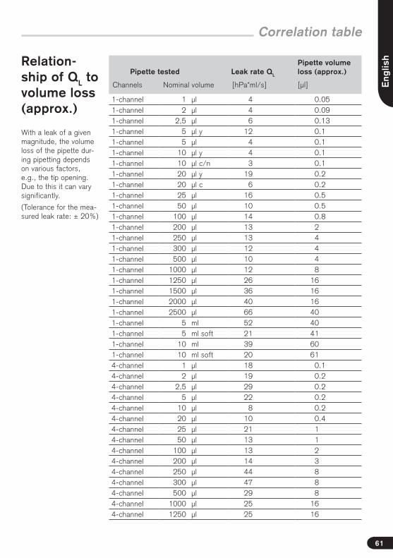
Eng
lish
Correlation table
Relation-ship of QL to volume loss (approx.)
Pipette tested Leak rate QL
Pipette volume loss (approx.)
Channels Nominal volume [hPa*ml/s] [μl]
1-channel 1 μl 4 0.051-channel 2 μl 4 0.091-channel 2,5 μl 6 0.131-channel 5 μl y 12 0.11-channel 5 μl 4 0.11-channel 10 μl y 4 0.11-channel 10 μl c/n 3 0.11-channel 20 μl y 19 0.21-channel 20 μl c 6 0.21-channel 25 μl 16 0.51-channel 50 μl 10 0.51-channel 100 μl 14 0.81-channel 200 μl 13 21-channel 250 μl 13 41-channel 300 μl 12 41-channel 500 μl 10 41-channel 1000 μl 12 81-channel 1250 μl 26 161-channel 1500 μl 36 161-channel 2000 μl 40 161-channel 2500 μl 66 401-channel 5 ml 52 401-channel 5 ml soft 21 411-channel 10 ml 39 601-channel 10 ml soft 20 614-channel 1 μl 18 0.14-channel 2 μl 19 0.24-channel 2,5 μl 29 0.24-channel 5 μl 22 0.24-channel 10 μl 8 0.24-channel 20 μl 10 0.44-channel 25 μl 21 14-channel 50 μl 13 14-channel 100 μl 13 24-channel 200 μl 14 34-channel 250 μl 44 84-channel 300 μl 47 84-channel 500 μl 29 84-channel 1000 μl 25 164-channel 1250 μl 25 16
With a leak of a given magnitude, the volume loss of the pipette dur-ing pipetting depends on various factors, e.g., the tip opening. Due to this it can vary significantly.
(Tolerance for the mea-sured leak rate: ± 20%)
61

Ordering Information · Accessories · Spare Parts
PLT unit (Pipet Leak Testing Unit) Including one adapter each for testing air-displace-ment pipettes with tip (mounted) and without tip, 2 blind plugs, 3 replacement PE filters for the pipette adapters, a universal AC adapter, and a quality certificate.
Cat. No. 7039 70
Pipette adapter for testing with tips for single-channel pipettes, including 1 blind plug
Cat. No. 7039 75
Pipette adapter for testing without tips for single-channel pipettes, including 1 blind plug
Cat. No. 7039 76
4-Channel pipette adapter for testing multi-chan-nel pipettes with and without tips, including 4 blind plugs
Cat. No. 7039 77
Filters for the pipette adapter PE, package of 10
Cat. No. 7039 78
Universal AC adapterInput: AC 100 V - 240 V, 50/60 HzOutput: DC 6.5 V, 800 mA
Cat. No. 7039 79
62
PLTconnect software For the documentation of examinations. Pack of 1.
Cat. No. 7039 80
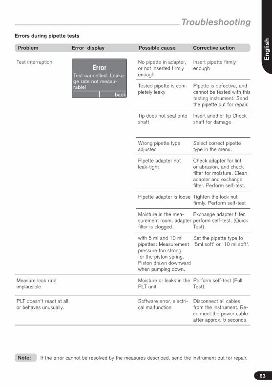
Eng
lish
Test interruption No pipette in adapter, or not inserted firmly enough
Insert pipette firmly enough
Tested pipette is com-pletely leaky
Pipette is defective, and cannot be tested with this testing instrument. Send the pipette out for repair.
Tip does not seal onto shaft
Insert another tip Check shaft for damage
Wrong pipette type adjusted
Select correct pipette type in the menu.
Pipette adapter not leak-tight
Check adapter for lint or abrasion, and check filter for moisture. Clean adapter and exchange filter. Perform self-test.
Pipette adapter is loose Tighten the lock nut firmly. Perform self-test
Moisture in the mea-surement room, adapter filter is clogged.
Exchange adapter filter, perform self-test. (Quick Test)
with 5 ml and 10 ml pipettes: Measurement pressure too strong for the piston spring. Piston drawn downward when pumping down.
Set the pipette type to '5ml soft' or '10 ml soft'.
Measure leak rate implausible
Moisture or leaks in the PLT unit
Perform self-test (Full Test).
PLT doesn't react at all, or behaves unusually.
Software error, electri-cal malfunction
Disconnect all cables from the instrument. Re-connect the power cable after approx. 5 seconds.
Troubleshooting
Problem Error display Possible cause Corrective action
ErrorTest cancelled: Leaka-ge rate not measu-rable!
back
Errors during pipette tests
If the error cannot be resolved by the measures described, send the instrument out for repair.Note:
63
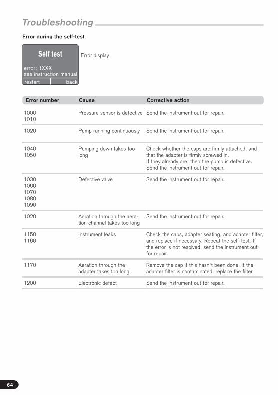
Troubleshooting
10001010
Pressure sensor is defective Send the instrument out for repair.
1020 Pump running continuously Send the instrument out for repair.
10401050
Pumping down takes too long
Check whether the caps are firmly attached, and that the adapter is firmly screwed in.If they already are, then the pump is defective. Send the instrument out for repair.
10301060107010801090
Defective valve Send the instrument out for repair.
1020 Aeration through the aera-tion channel takes too long
Send the instrument out for repair.
11501160
Instrument leaks Check the caps, adapter seating, and adapter filter, and replace if necessary. Repeat the self-test. If the error is not resolved, send the instrument out for repair.
1170 Aeration through the adapter takes too long
Remove the cap if this hasn't been done. If the adapter filter is contaminated, replace the filter.
1200 Electronic defect Send the instrument out for repair.
Error number Cause Corrective action
Self test
error: 1XXXsee instruction manual
backrestart
Error during the self-test
Error display
64

Eng
lish
65
Repairs · contact addresses
– Clean and decontaminate the instrument carefully.
– It is essential always to include an exact description of the type of malfunc-tion and the media used. If information regarding media used is missing, the instrument cannot be repaired. If information regarding media used is missing, the instrument cannot be repaired.
– Shipment is at the risk and the cost of the sender.
Outside the U.S. and Canada:
– Complete the “Declaration on Absence of Health Hazards” and send the instru-ment to the manufacturer or supplier. Ask your supplier or manufacturer for the form. The form can also be downloaded from www.brand.de.
In the U.S. and Canada:
– Contact BrandTech Scientific, Inc. and obtain authorization for the return before sending your instrument for service.
– Return only cleaned and decontaminated instruments, with the Return Authorization Number prominently displayed on the outside of the package to the address provided with the Return Authorization Number.
BRAND GMBH + CO KGOtto-Schott-Straße 2597877 Wertheim (Germany)
Tel.: +49 9342 808-0Fax: +49 9342 808-98000E-Mail: [email protected]
USA and Canada:BrandTech® Scientific, Inc.11 Bokum RoadEssex, CT 06426-1506 (USA)
Tel.: +1-860-767 2562Fax: +1-860-767 2563www.brandtech.com
India:BRAND Scientific Equipment Pvt. Ltd. 303, 3rd Floor, ‘C‘ Wing, DelphiHiranandani Business Park, PowaiMumbai - 400 076 (India)
Tel.: +91 22 42957790 Fax: +91 22 42957791 E-Mail: [email protected] www.brand.co.in
China:BRAND (Shanghai) Trading Co., Ltd. Guangqi Culture Plaza Room 506, Building B No. 2899, Xietu Road Shanghai 200030 (P.R. China)
Tel.: +86 21 6422 2318Fax: +86 21 6422 2268 E-Mail: [email protected]
Contact addresses
Return for repair
Important! Transporting of hazardous materials without a permit is a violation of federal law.

Subject to technical modification without notice. Errors excepted.
Disposal
The adjoining symbol means that storage batteries and electronic devices must be disposed of separately from household trash (mixed municipal waste) at the end of their service life.
- According to the Directive 2002/96/EC of the European Parliament and of the Council on Waste Electrical and Electronic Equipment (WEEE) of 27 January 2003, electronic equipment requires disposal according to the relevant national disposal regulations.
66
We shall not be liable for the consequences of improper handling, use, servic-ing, operating or unauthorized repairs of the instrument or the consequences of normal wear and tear especially of wearing parts such as pistons, seals, valves and the breakage of glass as well as the failure to follow the instruc-tions of the operating manual. We are not liable for damage resulting from any actions not described in the operating manual or if non-original spare parts or components have been used.
U.S. and Canada:Information for warranty please see www.brandtech.com.
Warranty

BRAND GMBH + CO KG has made reasonable efforts to ensure that hazardous materials and substan-ces may not be used in BRAND products.In order to determine the concentration of hazardous substances in all homogeneous materials of the subassemblies, a “Product Conformity Assessment” (PCA) procedure was performed. As defined in GB/T 26572 the “Maximum Concentration Value” limits (MCV) apply to these restricted substances:
DECLARATION OF CONFORMITY – Ch ina RoHS 2
Environmental Friendly Use Period (EFUP)
EFUP defines the period in years during which the hazardous substances con-tained in electrical and electronic products will not leak or mutate under normal operating conditions. During normal use by the user such electrical and electronic products will not result in serious environmental pollution, cause serious bodily injury or damage to the user’s assets.The environmental Friendly Use Period for BRAND instruments is 40 years.
此表格是按照SJ/T 11364-2014中规定所制定的。This table is created according to SJ/T 11364-2014.
l Lead (Pb): 0.1%l Mercury (Hg): 0.1%l Cadmium (Cd): 0.01%l Hexavalent chromium (Cr(+VI)): 0.1%l Polybrominated biphenlys (PBB): 0.1%l Polybrominated diphenyl ether (PBDE): 0.1%
MATERIAL CONTENT DECLARATION FOR BRAND PRODUCTS
有毒有害物质或元素Hazardous substances
部件名称Part name
铅Pb
汞Hg
镉Cd
六价铬Cr(+VI)
多溴联苯PBB
多溴二苯醚
PBDE
环保期限标识EFUP
包装 / Packaging O O O O O O
塑料外壳 / 组件Plastic housing / parts
O O O O O O
电池 / Battery O O O O O O
玻璃 / Glass O O O O O O
电子电气组件Electrical and electronic parts
X X X O O O
金属外壳 / 组件Metal housing / parts
X O O O O O
电机 / Motor X O O O O O
配件 / Accessories X O O O O O
10
BRAND GMBH + CO KG · Otto-Schott-Str. 25 · 97877 Wertheim · GermanyTel.: +49 9342 808-0 · Fax: +49 9342 808-98000 · E-Mail: [email protected]
Internet: www.brand.de
O: 表示该有毒有害物质在该部件所有均质材料中的含量均在GB/T 26572规定的限量要求以下。
O: Indicates that the above mentioned hazardous substance contained in all homogeneous materi-als of the part is below the required limit as defined in GB/T 26572.
X: 表示该有毒有害物质至少在该部件某一均质材料中的含量超出GB/T 26572规定的限量要
求。X: Indicates that the above mentioned hazardous substance contained in at least one of the homo-
geneous materials of this part is above the required limit as defined in GB/T 26572.
除上表所示信息外,还需声明的是,这些部件并非是有意用铅((Pb), 汞 ((Hg), 铬((Cd), 六价铬 (Cr(+VI)), 多溴联苯((PBB)(或多溴二苯醚((PBDE)(来制造的。Apart from the disclosures in the above table, the subassemblies are not intentionally manufactured or formulated with lead (Pb), mercury (Hg), cadmium (Cd), hexavalent chromium (Cr+VI), polybrominated biphenyls (PBB), and polybrominated diphenyl ethers (PBDE). Products manufactured by BRAND may enter into further devices or can be used together with other appliances. With these third party products and appliances in particular, please note the EFUP labeled on these products. BRAND will not take responsibility for the EFUP of those products and appliances.
Hans-Walter Kern(Managing Director Logistics and Production)
Place, date: Wertheim, 25/02/2019i.A.Josef Pfohl(Quality Managment)
注释:此表格适用于所有产品。以上列出的元件或组件不一定都属于所附产品的组成。Note: Table applies to all products. Some of the components or parts listed above may not be
part of the enclosed product.


9979 60 · Printed in Germany · 5/0319/5