
Repositório Institucional da Universidade de Brasília ... · from normative body ABNT NBR IEC...
13
Esta licença está disponível em: https://creativecommons.org/licenses/by-nc/4.0/ Repositório Institucional da Universidade de Brasília repositorio.unb.br Este artigo está licenciado sob uma licença Creative Commons Atribuição-NãoComercial 4.0 Internacional. Você tem direito de: Compartilhar — copiar e redistribuir o material em qualquer suporte ou formato. Adaptar — remixar, transformar, e criar a partir do material. De acordo com os termos seguintes: Atribuição — Você deve dar o crédito apropriado , prover um link para a licença e indicar se mudanças foram feitas . Você deve fazê-lo em qualquer circunstância razoável, mas de maneira alguma que sugira ao licenciante a apoiar você ou o seu uso Não Comercial — Você não pode usar o material para fins comerciais . Sem restrições adicionais — Você não pode aplicar termos jurídicos ou medidas de caráter tecnológico que restrinjam legalmente outros de fazerem algo que a licença permita. This article is licensed under a Creative Commons Attribution-NonCommercial 4.0 International License. You are free to: Share — copy and redistribute the material in any medium or format. Adapt — remix, transform, and build upon the material. Under the following terms: Attribution — You must give appropriate credit , provide a link to the license, and indicate if changes were made . You may do so in any reasonable manner, but not in any way that suggests the licensor endorses you or your use. NonCommercial — You may not use the material for commercial purposes . No additional restrictions — You may not apply legal terms or technological measures that legally restrict others from doing anything the license permits.
Transcript of Repositório Institucional da Universidade de Brasília ... · from normative body ABNT NBR IEC...

Esta licença está disponível em: https://creativecommons.org/licenses/by-nc/4.0/
Repositório Institucional da Universidade de Brasília repositorio.unb.br
Este artigo está licenciado sob uma licença Creative Commons Atribuição-NãoComercial 4.0
Internacional.
Você tem direito de:
Compartilhar — copiar e redistribuir o material em qualquer suporte ou formato.
Adaptar — remixar, transformar, e criar a partir do material.
De acordo com os termos seguintes:
Atribuição — Você deve dar o crédito apropriado, prover um link para a licença e indicar se mudanças foram feitas. Você deve fazê-lo em qualquer circunstância razoável, mas de maneira alguma que sugira ao licenciante a apoiar você ou o seu uso
Não Comercial — Você não pode usar o material para fins comerciais.
Sem restrições adicionais — Você não pode aplicar termos jurídicos ou medidas de caráter
tecnológico que restrinjam legalmente outros de fazerem algo que a licença permita.
This article is licensed under a Creative Commons Attribution-NonCommercial 4.0 International
License.
You are free to:
Share — copy and redistribute the material in any medium or format.
Adapt — remix, transform, and build upon the material.
Under the following terms:
Attribution — You must give appropriate credit, provide a link to the license, and indicate if changes were made. You may do so in any reasonable manner, but not in any way that suggests the licensor endorses you or your use.
NonCommercial — You may not use the material for commercial purposes.
No additional restrictions — You may not apply legal terms or technological measures that legally restrict others from doing anything the license permits.
Original Articlehttp://dx.doi.org/10.1590/rbeb.2014.017
*e-mail: [email protected] Received: 07 February 2013 / Accepted: 19 February 2014
Control system for continuous positive airway pressure
Mileny Ximenes Oliveira*, Amilton dos Reis Capistrano, Suélia de Siqueira Rodrigues Fleury Rosa, José Felício Silva, Adson Ferreira da Rocha, Hervaldo Sampaio Carvalho
Abstract Introduction: Continuous Positive Airway Pressure (CPAP) is a mode of non-invasive mechanical ventilation commonly used in neonatology. The incorporation of new therapeutic and technological advances may impact the survival of very low birth weight preterm infants. However, one of the difficulties faced is the high cost of this device and its numerous add-on functions, such as Apnea Hypopnea Index (AHI), flow limitation, among others. Thus, in this study, we aim to address the design and construction of a CPAP device prototype to be used in a Neonatal Intensive Care Unit (NICU). Methods: In order to design the experimental CPAP device with sensory instrumentation for providing data to a micro-controlled system, electro-pneumatic circuits and signal conditioning boards of sensors have been fitted to achieve optimized CPAP function with low energy consumption. While running this setup, a metrological study was carried out to evaluate the sensors’ performance. The methodology employed for the study was the IDOV (Identify, Design, Optimize, and Validate) method, a variant of six sigma, to minimize the failure rates. It is expected that it works under valve activation to maintain positive pressure in the airways of the patient (neonate). Results: The whole system performs satisfactorily (low noise level) for each assessed module. Additionally, it is emphasized that software development for application control has resulted in a significant improvement of hardware functions. Conclusion: In this work, a system that performs the CPAP function was obtained; the research has shown that, by adopting a specific purpose, it may create a better understanding of Assistive Technology.Keywords CPAP, Microcontroller, Newborns, Sensing, Pneumatics.
IntroductionPulmonary disorders represent one of the most common diagnoses in preterm newborns admitted to neonatal units, occurring more often than Infant Respiratory Distress Syndrome (IRDS) (previously called Hyaline Membrane Disease -HMD), Pulmonary Edema, Atelectasis, Apnea of Prematurity (AOP), and Transient Tachypnea of the Newborn (TTN). Additionally, these pulmonary disorders are among the top causes of death in preterm infants worldwide (Margoto, 2004); the overall incidence of Infant Respiratory Distress Syndrome (IRDS) in newborns is approximately 2%, with preterm infants being more prone to IRDS. A newborns’ breathing during the first few hours of life is more rapid and labored than normal because of a lack of pulmonary surfactant. (Kaczka and Smallwood, 2012; MacDonald et al., 2012). Pulmonary surfactant is an oily substance produced by the cells lining the alveoli; it reduces the surface tension within the alveoli, preventing their collapse, and thus allowing proper breathing of the newborn infant (Speer, 2011). Therefore, right after birth, the infant needs to start breathing regularly and effectively to survive. However, in premature infants, usually the lung has not produced enough surfactant to keep breathing normally, resulting in difficulty in breathing that may lead to death within
a few days (MacDonald et al., 2012; Schoenwolf, 2009; Speer, 2011).
Over the last few decades, neonatal care has advanced significantly and is closely related with the development of more effective actions for controlling respiratory insufficiency. For treatment of such diseases, a non-invasive positive pressure mode of ventilation, a special type of mechanical ventilation, called Continuous Positive Airway Pressure (CPAP) is used. Today, besides the above applications, it is also used in neonates with very low birth weight - less than 1500 grams (Margoto, 2004).
CPAP applies a continuous airflow into the patient’s airways through the nose or both nose and mouth by using a mask; this airflow ensures an internal positive pressure to the newborns’ lungs, avoiding the pulmonary alveoli failure. Moreover, this type of mechanical ventilation helps the development of the patient’s breathing due to improvement in oxygenation of the tissues (Ammari et al., 2005). Preterm infants, who usually show physical signs of prematurity, such as Infant Respiratory Distress Syndrome (IRDS), Pulmonary edema or lung disorders, have also shown improved outcomes by using CPAP (Jones, 1996). It was verified that nasofacial CPAP with PEEP 5
Volume 30, Número 2, p. 102-113, 2014
CPAP for newborn infants
cmH2O was shown to be effective in improving arterial oxygenation with lower FiO2, in decreasing breathing frequency (respiratory rate - RR), thus reducing the need for invasive ventilation, and also proved to be safe for use with an open oxygen mask (Silva, 2007). Additionally, it proves that CPAP may be used safely and effectively by coupling masks, to prevent the use of invasive ventilation, which would be more traumatic.
The device, in addition to maintaining a continuous flow of gas mixture inhalation, offers a mechanism for generating a positive pressure by connecting the system to the patient’s airways (Rugolo, 2001). Pressure monitoring is needed for reducing respiratory resistance because pressure variations in the airways may increase the patient’ respiratory effort (depending on the respiratory flow, which if higher, increases the patient’s respiratory effort). In the commercial CPAP device Inter3®, according to Lima et al. (2004), the following values were obtained at medium flow pressure rates of 8, 10 and 12 per l/min, (pressure ranges and standard deviation):
• Continuous positive airway pressure (CPAP) with 3 cmH2O: we found 2.26 ± 0.41 cmH2O, 2.22 ± 0.37 cmH2O and 2.04 ± 0.41 cmH2O;
• Positive end-expiratory pressure (PEEP) with 5 cmH2O: we found 3.96 ± 0.41 cmH2O, 3.87 ± 0.43 cmH2O and 3.75 ± 0.52 cmH2O;
• Positive end-expiratory pressure (PEEP) with 6 cmH2O: we found 4.94 ± 0.40 cmH2O, 4.85 ± 0.41 cmH2O and 4.72 ± 0.37 cmH2O.
In this system, the key factor is related to the inhaled gas, resulting from compressed air and O2, which is heated to near body temperature and humidified, and then attached to an oxygen analyzer and a flow meter for controlling airflow and Fraction of Inspired Oxygen (FiO2), which are provided to the patient. We have defined Non-Invasive Ventilation (NIV) as a method by which a mask or similar device, has the role of promoting patient/ventilator connection without using an endotracheal tube, thus supplying adequate gas exchange and reducing the patient’s breathing effort.
A CPAP is a (travel sized) portable machine that delivers warmed and humidified air or oxygen/air mixtures to patient via nasal prongs (Koti, 2009). However, the machines available in the market are quite expensive; they also usually add numerous functions that further increase the prices. From this perspective, this study aims to present an inexpensive experimental CPAP for respiratory support to be employed in a Neonatal Intensive Care Unit (NICU). The system is based on an automated environment, thus enabling control over the pressure of gas flow
provided to the neonate. The device comprises of three modules: interface, electro-pneumatic and micro-controlled module, which is responsible for collecting data from sensors and decision-making. The criteria applied in the designed modules are taken from normative body ABNT NBR IEC 60601-2-12 (Associação…, 2004).
MethodsIn the designed CPAP, compressed air and oxygen are the input variables, and the output variable is the humidified air/air mixture delivered to the patient. By means of a control panel, the machine provides to the operator, a gas flow control to reach the adequate gas mixture, and a way of setting the Positive end- expiratory Pressure (PEEP). These numbers are established by the machine operator using a keyboard on the control panel, where data are entered and then read by the equipment and presented on an LCD display. The electro-pneumatic module consists of two Proportional Control Valves EC-P-05-4050-E-M5 by ClippardMinimatic®, 5 VDC, Input Current Range 0.370A and working pressure from 0 to 3515.44 cmH2O. The pressure regulator valves are used for controlling oxygen and airflow coming from the hospital supply chain or an ambulance, thus ensuring stability of the working pressure and maintaining a stable output flow. Upon activation, proportional valves start matching the gas flow, through the regulator, to gas (value) sets on the system. The mixture of gas, compressed air, and oxygen, is directed to the mixer/gas cylinder (pressure storage reservoir), where it is homogenized. The measuring element functions to determine when the input flow is equal to the output flow. The output device includes a flow sensor that senses the rates of fluid flow delivered to patient, and a pressure regulator that regulates patients’ inhalation gas pressure. This pressure is adjusted by the user by setting PEEP.
The Electronic Exhalation Valve 5000249 by Magnamed Tecnologia Médica Ltda® (Magnamed, 2007), has voltage 12 VDC, Input Current Range 0.37A and working pressure of 120 cmH2O. The valve is designed for controlling PEEP, and if the load flow increases up to 3 cmH2O above PEEP, the flow regulator may behave as safety valve, thereby depressurizing the equipment internally for a few seconds to ensure accurate pressure control. In the case of failure of PEEP valve control, the safety valve will open when the internal pressure reaches a value equal to, or above 30 cmH2O, thus protecting the patient’s respiratory system from being subject to high pressure. If due to some failure, the gas mixture was not forwarded to the output Inspiratory limb,
Rev. Bras. Eng. Bioméd., v. 30, n. 2, p. 102-113, jun. 2014Braz. J. Biom. Eng., 30(2), 102-113, June 2014 103
Oliveira MX, Capistrano AR, Rosa SSRF, Silva JF, Rocha HD, Carvalho HS
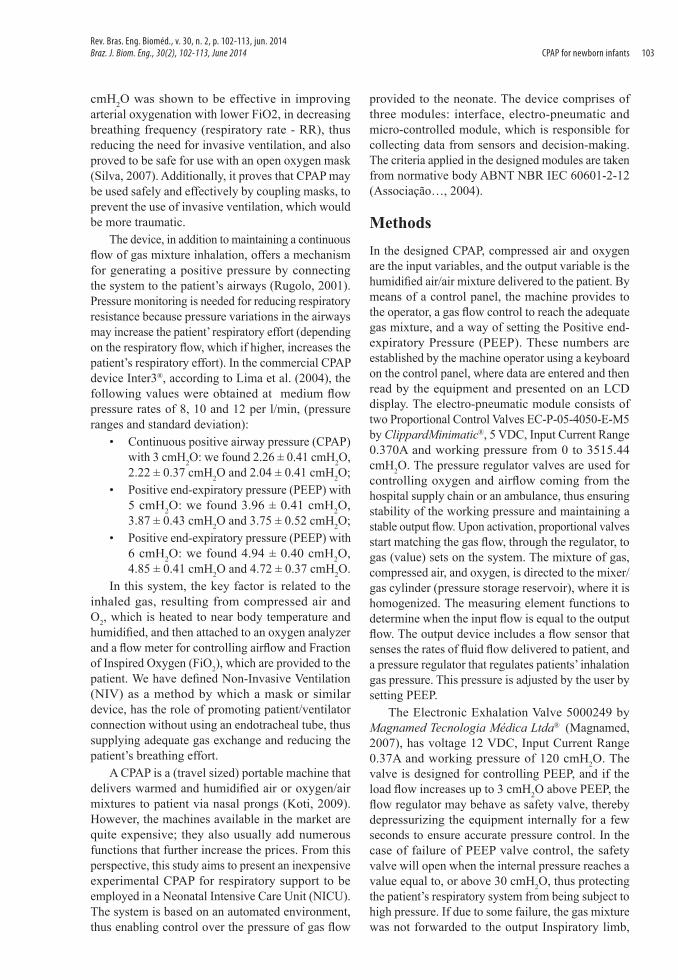
the patient may mechanically trigger the emergency valve, which provides a negative pressure from 0 to -2 cmH2O; it will allow the patient to maintain spontaneous breathing through ambient air. For measuring circuit of pressure and flow, the Absolute Pressure Sensor - MPX5700AP and the Differential Pressure Sensor - MPX10DP, both manufactured by Motorola, are used, respectively. For measuring the inhalation flow, Neonate flow sensor 3201471 by Magnamed Tecnologia Médica Ltda® is used. Its input pressure, for instance, offered by the supply chain of medical oxygen, is monitored by Absolute Pressure Sensors, due to their ability to work with pressures ranging from 0 to 7 kgf/cm2 with no damages. Differential pressure sensors such as gauge, effectively performs the mathematical operation of subtraction through mechanical means, thus obviating the need for an operator or control system to watch two separate gauges and determine the difference in readings, i.e., it makes the readings in the output device, thus ensuring that pressure offered to the patient is in accordance with the setting on the equipment. The flow sensor is coupled with a differential sensor for monitoring flow applied to the patient. Figure 1 shows a pneumatic block diagram, presenting the position of aforementioned components.
Integration of circuit sensors to the valve systems is via a MSP-EXP430G2 Launch Pad microcontroller, which allows for controlling the whole system in accordance with the values given on the machine’s control panel. The outputs of the microcontroller
start and control valves via an integrated ULN 2003A (drive) circuit.
Pressure measures
For tests on circuits with the MPX10DP sensor, a pressure gauge (manufactured by Engineering and Biomaterial Lab – BioEnGLab®) was used for each water column, so that the pressure can be analyzed by the height of a water column, given a zero - cmH2O - reference point of the atmospheric pressure. Separate tests were performed in circuits, with five repetitions for each cmH2O, increasing or decreasing at the pressure gauge.
Flow measurement
The circuit with a MPX10DP sensor has been calibrated by applying different rates of pressure on its inputs, using a pressure gauge for water column. From each one of the five tests, thirty five pressure points were collected, with variation of 1 cmH2O between them.
The MPX10DP sensor is appropriate for differential pressure measurements between 0 and 100 cmH2O. It provides a very accurate and linear output voltage, directly proportional to the applied pressure on its inputs. The potential difference (voltage) between these terminals corresponds to the differential pressure applied on the component, and ranges from 55 to 20 mV. For achieving this voltage, an instrumentation amplifier, the INA118P, is used; the amplifier is responsible for measuring the voltage between the sensor outputs and performing signal amplification
Figure 1. Block diagram of the pneumatic system developed. The symbology: O2 network - O2 offered by the network; Air - air offered by the network; S1 and S2 - pressure sensors MPX5700AP 1 and 2; VP1 and VP2 - proportional valves 1 and 2; mixer; S3 - pressure sensor MPX10DP associated sensor flow; VSM - mechanical safety valve; VSE - electrical safety valve - VE: expiratory valve and patient.
Rev. Bras. Eng. Bioméd., v. 30, n.2, p. 102-113, jun. 2014Braz. J. Biom. Eng., 30(2), 102-113, June 2014104
CPAP for newborn infants
(Motorola, 1997). The sensor runs due to a pressure variation between its inputs. When the variance is zero, i.e., when the pressures on its inputs are equal, there is an offset voltage of approximately:
28.5mV=oV (1)
Thus, for each pressure variation measured between its inputs, the circuit output has voltage equal to:
( 28.5) mV= × δ +oV A V (2)
where δV is a variation of voltage, an increasing or decreasing function of applied pressure at the input sensor, and A, the amplification factor (gain) of the signal.
Amplification (gain)
The instrumentation amplifier INA 118P has its amplification defined by resistor gain RG. The formula applied for calculating gain is:
50.0001= +G
AR (3)
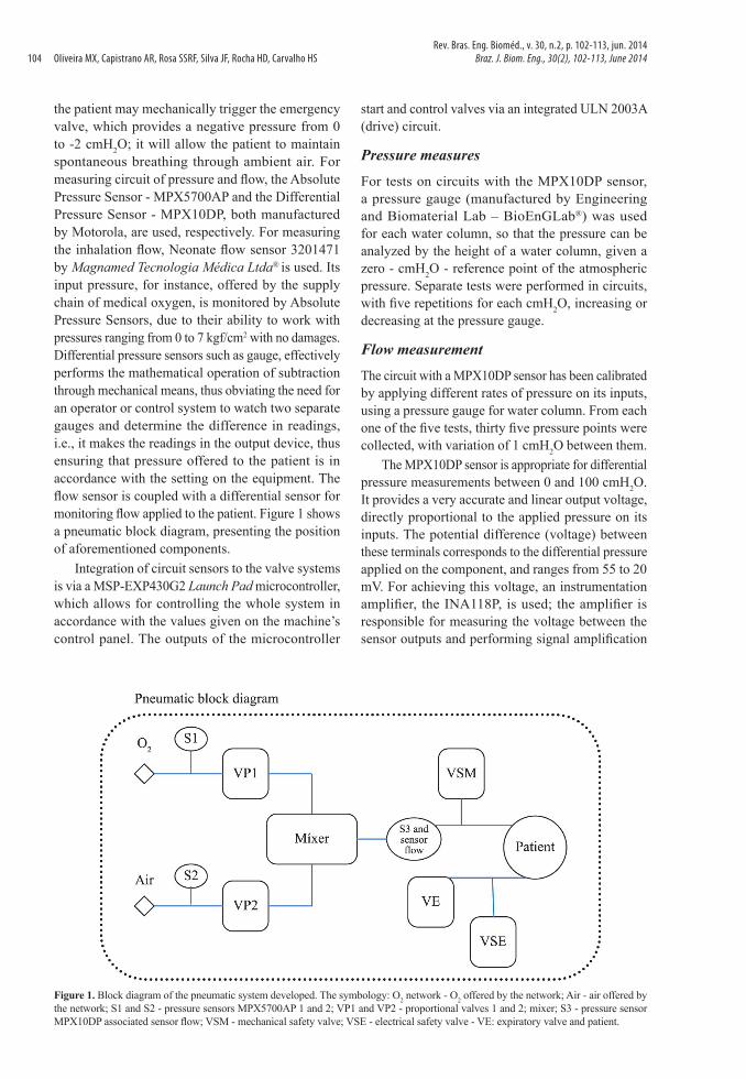
Thus, by using resistors of 10 kW, the gain is 6 V/V. The lower voltage gain allows the maintenance of linearity on the output circuit and avoids amplifiers saturation. Then, the circuit is completed with a unitary gain amplifier (buffer) for coupling with other loads, to maintain a stable gain when connected to the micro-controlled module. Figure 2 shows in (a) the circuit diagram, and in (b), the implemented circuit board.
The chosen flow sensor is selected for medical use in newborn infants, for non-invasive applications; it has reduced dimensions and weight, approximately 5.6 cm and 9.0 g, is compatible with gas mixtures, such as O2 and air, and enables measurements of flow and proximal or distal pressure. The sensor has different diameters on its ends, because of which, it offers different pressures (which varies in function of this size) on its outputs. Therefore, the flow pressure
MPX10DP sensor offers differential pressures on the output Inspiratory limb.
Pressure measurementsSensor MPX5700AP measures relative pressures, and therefore, builds upon the atmospheric pressure to determine the pressure applied on its input. It works with higher pressures, ranging from 0 to 7138 cmH2O (Motorola, 2009) and also provides voltage between 0.2 and 4.7 V, with an output offset voltage of approximately 0.767 V. Moreover, it is responsible for monitoring air pressure and oxygen provided by the supply chain of hospital or the mobile unit (ambulance). The circuit diagram containing the transducer comprises only the aforementioned device and a unitary gain amplifier (buffer) to maintain the system output signal.
The circuit shows that the MPX5700AP sensor has been calibrated by applying distinct pressures on its input; a digital pressure gauge, model DPI 705, was used for this process. Each of the three tests performed has collected fifteen pressure points, ranging from 204 to 306 cmH2O. This variation was higher compared to the MPX10DP sensor calibration because the dynamic range MPX5700AP sensor allows higher pressure measurements.
MicrocontrollersThe Microcontrollers System is responsible for decision-making and consists of two microcontrollers, both being M430G2553, from the MSP-EXP430G2 Launch Pad set, manufactured by Texas Instruments®. This system sets the conversion of the analog signals from the sensing circuits into digital signals, which are processed and analyzed by software. As a result, microcontrollers operate upon the valves and give the data from the sensors being monitored to the user. It is also responsible for audio and visual alarms whenever the device does not provide values in agreement with those established by the user, or whenever an error occurs.
Figure 2. (a) Electronic circuit used to capture the signal with the sensor MPX10DP. (b) Circuit board (PCB): (1) - Sensor MPX10DP. (2) - Operational Amplifier TL072CN. (3) - Instrumentation Amplifier INA118P. (4) - Connectors to power supply.
Rev. Bras. Eng. Bioméd., v. 30, n. 2, p. 102-113, jun. 2014Braz. J. Biom. Eng., 30(2), 102-113, June 2014 105
Oliveira MX, Capistrano AR, Rosa SSRF, Silva JF, Rocha HD, Carvalho HS
The microcontrollers’ features are: i) 16 kB Flash; ii) 10-Bit Successive Approximation by Recorders (SAR) A/D; iii) 16-Bit RISC Architecture, 62.5-ns Instruction Cycle Time; iv) 2 Timers; v) 24 Touch-Sense, Enabled and I/O Pins; vi) Low Supply-Voltage Range -1.8 V to 3.6 V (Texas Instruments, 2006).
SoftwareTwo codes were developed in the C programming language to fulfill equipment functions, as the system has two microcontrollers. The first code, i.e., the first microcontroller, is responsible for capturing and processing signals of the sensor and is also responsible for activation of the valves; therefore, this microcontroller is designed to control pneumatic drives and read equipment sensors. The second code controls a LCD display, where data from sensors is shown and allows setting the visualization of O2, air and PEEP levels; this microcontroller is primarily for the user. Thus, communication between them is necessary and is part of the codes of the two microcontrollers. Each microcontroller is responsible for a number of input and output variables. For the first microcontroller, the input variables consist of signs taken from five pressure sensors and user adjustment buttons. In addition, the opening or closing controls of the three valves of the system, two of which are proportional valves, serve as output. These valves are controlled by Pulse-Width Modulation (PWM), i.e., via software, in which square waves are generated with a frequency of oscillation that will load and control the valves, so that they will remain proportionally open with respect to a particular wave generated by PWM. As these waves have a higher frequency, the valve powered by this signal will remain more open when the system requests for a smaller opening; consequently, the wave will have a lower frequency,
and the valve will remain less open . For the second microcontroller, the input variables are represented by the values entered by the user on it, and the output variables are shown on the LCD display.
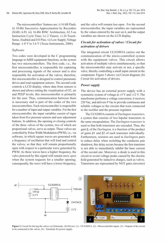
Circuit for activation of valves / Circuit for activation of driversThe integrated circuit ULN2003A carries out the communication of the micro-controlled system with the equipment valves. This circuit allows activation of multiple valves simultaneously, so that the microcontroller may activate or not, a specific valve, thereby controlling a small input current in the component. Figure 3 shows: (a) Circuit diagram; (b) Circuit for activation of drivers.
Power supplyThe device has an external power supply with a symmetric system of voltage at ±5 V and ±12 V. The transformer performs a voltage conversion; it receives 220 Vac, and delivers 9 Vac to provide continuous and reliable voltages to the circuits that were connected to the rectifier and the pressure regulator.
The ULN2003A consists of Darlington transistors, a system that consists of two bipolar transistors in the same encapsulation. The Darlington transistor is used so that both transistors are cascaded. Thus, the gain β, of the Darlington, is a function of the product of gains β1 and β2 of each transistor individually. Furthermore, resistors are used in Darlington pairs to reduce delay when switching the conductor pair shutdown; this delay occurs because the first transistor is not able to immediately inhibit the base current of the second one. Moreover, a diode is used in this circuit to avoid voltage peaks caused by the electric field generated by inductive charges, such as valves. Transistors are represented by NOT gates (inverter)
Figure 3. Circuit for driving the valves: (a) Schematic. (b) Drivers: (1) - ULN2003A. (2) - Microcontroller inputs. (3) - Outputs of the circuit to be connected to the valves. (4) - Terminals for power supply.
Rev. Bras. Eng. Bioméd., v. 30, n.2, p. 102-113, jun. 2014Braz. J. Biom. Eng., 30(2), 102-113, June 2014106
CPAP for newborn infants
because of their operating features: i) Input current in logic level 1, which is approximately 3.5 V at the microcontroller output; the resistor in this circuit has a small capacity difference between its terminals, and the base voltage of the Darlington transistor is high. Therefore, the transistor operates in saturation mode because the base voltage is higher than the collector base voltage, and the collector voltage, or the output current, is approximately zero, i.e., does not allow the opening of the valve; ii) Input current in logic level 0, the capacity difference between resistors’ terminals is larger and thus, we have an input current given by:
3.3 22150
= =ΩINVI mA (4)
Because of the Darlington transistor, which features a high gain resulting from the logic level 0 on its input, the output circuit current has adequate value for activation of the valves.
Pneumatic block
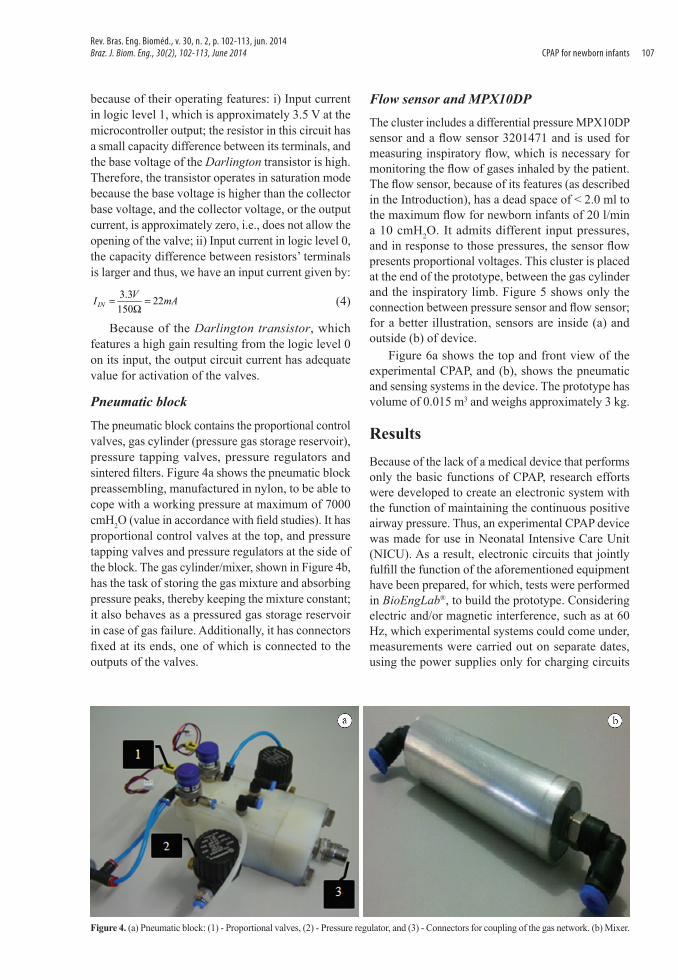
The pneumatic block contains the proportional control valves, gas cylinder (pressure gas storage reservoir), pressure tapping valves, pressure regulators and sintered filters. Figure 4a shows the pneumatic block preassembling, manufactured in nylon, to be able to cope with a working pressure at maximum of 7000 cmH2O (value in accordance with field studies). It has proportional control valves at the top, and pressure tapping valves and pressure regulators at the side of the block. The gas cylinder/mixer, shown in Figure 4b, has the task of storing the gas mixture and absorbing pressure peaks, thereby keeping the mixture constant; it also behaves as a pressured gas storage reservoir in case of gas failure. Additionally, it has connectors fixed at its ends, one of which is connected to the outputs of the valves.
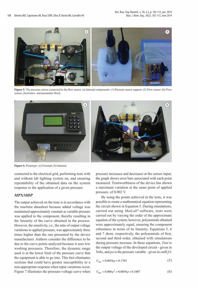
Flow sensor and MPX10DPThe cluster includes a differential pressure MPX10DP sensor and a flow sensor 3201471 and is used for measuring inspiratory flow, which is necessary for monitoring the flow of gases inhaled by the patient. The flow sensor, because of its features (as described in the Introduction), has a dead space of < 2.0 ml to the maximum flow for newborn infants of 20 l/min a 10 cmH2O. It admits different input pressures, and in response to those pressures, the sensor flow presents proportional voltages. This cluster is placed at the end of the prototype, between the gas cylinder and the inspiratory limb. Figure 5 shows only the connection between pressure sensor and flow sensor; for a better illustration, sensors are inside (a) and outside (b) of device.
Figure 6a shows the top and front view of the experimental CPAP, and (b), shows the pneumatic and sensing systems in the device. The prototype has volume of 0.015 m3 and weighs approximately 3 kg.
ResultsBecause of the lack of a medical device that performs only the basic functions of CPAP, research efforts were developed to create an electronic system with the function of maintaining the continuous positive airway pressure. Thus, an experimental CPAP device was made for use in Neonatal Intensive Care Unit (NICU). As a result, electronic circuits that jointly fulfill the function of the aforementioned equipment have been prepared, for which, tests were performed in BioEngLab®, to build the prototype. Considering electric and/or magnetic interference, such as at 60 Hz, which experimental systems could come under, measurements were carried out on separate dates, using the power supplies only for charging circuits
Figure 4. (a) Pneumatic block: (1) - Proportional valves, (2) - Pressure regulator, and (3) - Connectors for coupling of the gas network. (b) Mixer.
Rev. Bras. Eng. Bioméd., v. 30, n. 2, p. 102-113, jun. 2014Braz. J. Biom. Eng., 30(2), 102-113, June 2014 107
Oliveira MX, Capistrano AR, Rosa SSRF, Silva JF, Rocha HD, Carvalho HS
connected to the electrical grid, performing tests with and without lab lighting system on, and ensuring repeatability of the obtained data on the system response to the application of a given pressure.
MPX10DP
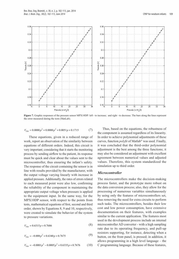
The output achieved on the tests is in accordance with the machine datasheet because added voltage was maintained approximately constant as variable pressure was applied to the component, thereby resulting in the linearity of the curve obtained in the process. However, the sensitivity, i.e., the ratio of output voltage variations to applied pressure, was approximately three times higher than the one presented by the device manufacturer. Authors consider the difference to be due to the curve points analyzed because it uses low working pressures. Therefore, the dynamic range used is at the lower limit of the pressure curve that the equipment is able to go into. This fact eliminates sections that could have greater susceptibility to a non-appropriate response when input variations occur. Figure 7 illustrates the pressure-voltage curve when
pressure increases and decreases at the sensor input; the graph shows error bars associated with each point measured. Trustworthiness of the device has shown a maximum variation at the same point of applied pressure, of 0.002 V.
By using the points achieved in the tests, it was possible to create a mathematical equation representing the circuit shown in Equation 5. During simulations, carried out using MatLab® software, tests were carried out by varying the order of the approximate equation of the system; however, polynomials obtained were approximately equal, ensuring the component robustness in terms of its linearity. Equations 5, 6 and 7 show, respectively, the polynomials of first, second and third order, obtained with simulations during pressure increase. In these equations, Vout is the output voltage of the developed circuit - given in Volts, and pa is the pressure variable - given in cmH2O:
0.0054 0.1703= +OutV p (5)
20.000 0.0054 0.1007= + +OutV p p (6)
Figure 5. The pressure sensor connected to the flow sensor. (a) Internal components: (1) Pressure sensor support; (2) Flow sensor. (b) Flow sensor, electronics and pneumatic block.
Figure 6. Prototype: (a) External; (b) Internal.
Rev. Bras. Eng. Bioméd., v. 30, n.2, p. 102-113, jun. 2014Braz. J. Biom. Eng., 30(2), 102-113, June 2014108
CPAP for newborn infants
3 20.0000 0.0000 0.0051 0.1715= + + +OutV p p p (7)
These equations, given in a reduced range of work, report an observation of the similarity between equations of different orders. Indeed, this circuit is very important; considering that it starts the monitoring process by sending airflow to the patient, its response must be quick and clear about the values sent to the microcontroller, thus ensuring the infant’s safety. The response of the circuit containing the sensor is in line with results provided by the manufacturer, with the output voltage varying linearly with increase in applied pressure. Additionally, the rates of errors related to each measured point were also low, confirming the reliability of the component in maintaining the appropriate output voltage when pressure is applied to the equipment input. In the same way, for the MPX10DP sensor, with respect to the points from tests, mathematical equations of first, second and third order, shown by Equations 8, 9 and 10, respectively, were created to simulate the behavior of the system to pressure variations.
0.6315 0.7686= +OutV p (8)
20.008 0.6340 0.7675= − + +OutV p p (9)
3 20.0001 0.0005 0.6335 0.7676= − − + +OutV p p p (10)
Thus, based on the equations, the robustness of the component is assumed regardless of its linearity. In order to achieve polynomial adjustments of these curves, function polyfit of Matlab® was used. Finally, it was concluded that the third-order polynomial adjustment is the best among the three functions; it may also be considered an adjustment with excellent agreement between numerical values and adjusted values. Therefore, this system standardized the simulation up to third order.
Microcontroller
The microcontrollers make the decision-making process faster, and the prototype more robust on the data conversion process; also, they allow for the processing of numerous variables simultaneously by using only the features of microcontrollers set, thus removing the need for extra circuits to perform such tasks. The microcontrollers, besides their low cost and low power consumption, have extensive documentation on their features, with examples similar to the current application. The features most used in the development process include an internal microcontroller AD converter - with a high sampling rate due to its operating frequency, and pull-up resistors supporting, for instance, detecting when a button, on the front panel, is pressed; in addition, it allows programming in a high level language – the C programming language. Because of these features,
Figure 7. Graphic responses of the pressure sensor MPX10DP: left - to increase; and right - to decrease. The bars along the lines represent the error measured during the tests (MatLab).
Rev. Bras. Eng. Bioméd., v. 30, n. 2, p. 102-113, jun. 2014Braz. J. Biom. Eng., 30(2), 102-113, June 2014 109
Oliveira MX, Capistrano AR, Rosa SSRF, Silva JF, Rocha HD, Carvalho HS
this set has advantages compared to others, such as Arduino (which costs almost nine times more) or MSP FET430 F2013, and despite belonging to the same family of microcontrollers, is able to work with less input and output variables. Moreover, to physically isolate the electro-pneumatic system of the micro-controlled system, a compartment with a height of approximately 4.0 cm was drawn up, and placed between the upper wall and the electro-pneumatic system. Additionally, at this location an aperture allows communication between the microcontroller and electronic circuits for controlling data.
SoftwareThe software used has an Integrated Development Environment (IDE) - Code Composer StudioTM (CCStudio), provided by Texas Instruments®, to integrate its family of processors. This environment includes a number of tools that made possible the construction and debugging of the software for the application. Developed in the C programming language, it allows the control of functionalities in a simple and intuitive way. E.g., Proportional Control Valves of pneumatic system are controlled by Pulse-Width Modulation (PWM); therefore, the work carried out via software for this application has involved a few registers previously defined by the manufacturer to operate under this modulation. Additionally, the manufacturer has provided various examples, which have been adapted to the pneumatic application or for controlling input and output variables (addressed for the user), keyboard and display, respectively. The implementation of communication between sensing systems and electro-pneumatic systems via software allows for the expansion of equipment functions, for instance, by inserting new provisions as alarms or temperature measurements. Furthermore, it is user-friendly, allowing people who did not took part in its development, to easily learn and contribute with new CPAP functionalities.
Valves systemFor controlling gas flow and for the mixture remains based on the values set by the user, two Proportional Control Valves - driven by microcontroller through the valve’s activation circuit – were used, each aimed at a type of gas. They ensure an output flow proportional to the current applied at the internal solenoid, thus ensuring a good flow control. Despite the variety of control options such as Direct Current (DC), Open/Closed-Loop Control, or Pulse-Width Modulation (PWM), was analyzed as its best use, particularly via DC, considering its low power consumption and the option for future modifications. Because steady
output flow depends on the patient’s characteristics such as weight, it was provided an expiratory valve for PEEP controlling, thus making its use safer. This valve has a linear actuator that allows precise control of pressures in respiratory circuits from a current applied directly to the actuator output. The controlled pressure is directly proportional to the applied current, which causes the displacement of the linear actuator. A constant applied force on the diaphragm blocks the outflow, so that, with increasing current, the passage of higher pressure is enabled and, with decreasing current, the pressure is lowered. However, if needed, excess gas is released into the atmosphere, thus allowing PEEP control to avoid high pressures that may cause barotrauma to the patient.
Because high temperatures in the equipment may cause damages to electronic components, and also variations on connectors of the pneumatic block, it was taken into account and the heat dissipation was monitored during device operation. For this purpose, openings were made at the rear of the prototype, and ventilation was forcefully inserted, thereby reducing its temperature. It should be emphasized that flow and pressure sensors control the output gas flow. Therefore, while the equipment is operating, the sensors should collect reliable data; otherwise, security measures will be taken by the microcontroller, such as opening the safety valve and launching an alarm message stating failure. Because the use of the flow sensor for newborn infants allows inspiratory flows up to 20 l/min, it may allow for in-vivo experimentation.
MetrologyFor the calibration process of transducer/pressure transmitter, the reference of the National Institute of Metrology (INMETRO-Brazil) was followed.
The process of measurement (calibration) should consider a number of elements, such as errors and external factors (temperature changes, noise, etc) that may affect the readings. Moreover, pressure measurements always have a reference value to come from. Additionally, is important to understand some concepts such as absolute pressure, gauge pressure, vacuum and differential pressure. Likewise, the unit of measurement for pressure is according to the International System of Units (SI), which uses Pascal (Pa). In this study, the unit of measurement kgf/cm2 was used. Firstly, prior to collecting the sample readings of transducers, the working pressure, which should be constant during the equipment usage, was stabilized. For this purpose, pressure regulators (of O2 and air) were adjusted. A double stage regulator
Rev. Bras. Eng. Bioméd., v. 30, n.2, p. 102-113, jun. 2014Braz. J. Biom. Eng., 30(2), 102-113, June 2014110
CPAP for newborn infants
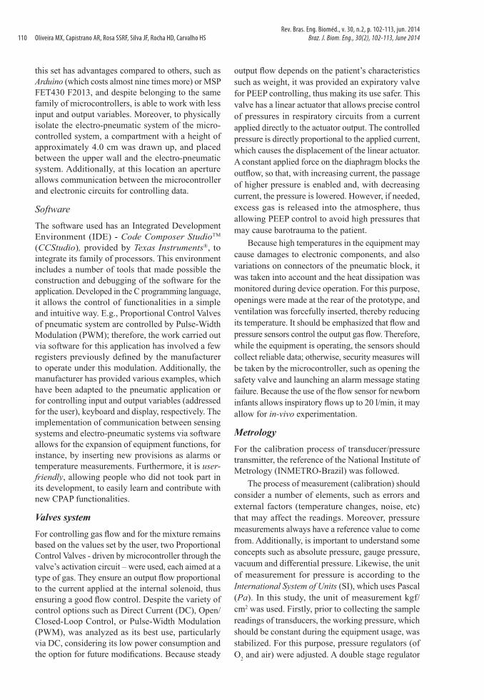
was placed at the output gas station of the hospital to limit the maximum pressure to 5 kgf/cm2, and then, an internal adjustment of each regulator was performed, by using different types of gas for each one. As a tool for comparison, a digital and calibrated pressure gauge model DPI 705 was used; it was adjusted to zero (0), and then connected to the output pressure regulator. Figure 8 shows the assembly and pressure value.
It is noteworthy that regulators were permanently fixed at this position to avoid changes in values of the pressure adjusted; from this point on, the curve from pressure transducer was determined individually. Ascending and descending curves were observed at several points. Once the equipment works at low pressures, the pressure will be maintained throughout the equipment service lifetime; changes can be made for more or less pressure, depending on the project needs. Additionally, tests of inspiratory flow may be performed to ensure that adjusted output flow is uniform, highlighting the fact that pressure peaks may cause patient trauma.
Discussion
The lungs of preterm infants are not fully developed and, therefore, are more susceptible to collapsing during exhalation. This is due to the high flexibility of the chest wall and the insufficient production of surfactant. These substances reduce surface tension at
the air-water interface within the alveoli, which are, in short, small balloon-like structures immersed in water; the higher the tension, the smaller (balloons) the alveoli become, and may possibly collapse during exhalation. The most widely used procedure for pediatric respiratory support is non-invasive mechanical ventilation, called CPAP. This technique applies a continuous airflow - a mixture of humidified and warmed air and O2 - into the patient’s airways to increase the pressure of gas mixture within the alveoli, keeping the thoracic cavity inflated, and avoiding pulmonary alveoli collapsing or failure. Thus, the patient receives the proper amount of gas mixture needed, and additionally, the risks associated with invasive devices, such as infections, are reduced. The CPAP device is currently made for a restricted number of manufacturers, most of them foreigners, represented mostly by North American and German companies; only one Brazilian company manufactures a CPAP device. Due to this lack of national manufacturers, CPAP has a high cost, especially for Public Health, and is therefore a restrictive factor. Additionally, foreign devices are too complicated and require specific training for their use.
In this sense, this work is focused on biomedical instrumentation research because the BioEngLab® group is interested in carrying out research to develop a low cost CPAP device with similar applications.
Figure 8. (1) Message indicating that the system will work with pressure stabilized by internal pressure regulators, so as not to suffer pressure variations when the client network is set at a higher value; (2) Test bench with the exhalation valve showing maximum pressure; (3) Zero set for the manometer and the ampere meter; (4) Pressure adjusted to 4 mbar - modulated pressure samples measured until pressure reached 40 mbar in the PEEP setting to evaluate the linearity of the pressure transducer. The maximum PEEP pressure was 30 mbar.
Rev. Bras. Eng. Bioméd., v. 30, n. 2, p. 102-113, jun. 2014Braz. J. Biom. Eng., 30(2), 102-113, June 2014 111
Oliveira MX, Capistrano AR, Rosa SSRF, Silva JF, Rocha HD, Carvalho HS
There are three testing stages: basic information, verification and validation. Basic information includes supplier evaluation, comparison of components from different suppliers and limiting components. Verification is the product “evolution process” in a stage, in order to ensure consistency and accuracy on standards, i.e., if product complies with a regulation, requirement and specifications for this stage of the project development. Finally, validation is the analysis process of system and subsystems requirements to evaluate if they meet the established specifications.
The methodology applied throughout the whole process aims to assess the functional status of the components, making the necessary adjustments and evaluating components’ behavior individually, thereby avoiding errors that may spoil future phases of the projects. With the results achieved, it could be seen that the system is sufficiently effective. The selection of sensors was the most cautious stage of this project, and analysis of power supply conditions, calibration, sensitivity, among other procedures, was crucial for their operation. Therefore, most of the time, carefully selected components with robust medical aspects, a requirement not easy to comply considering their low cost, were successfully employed.
Today, there are few operating modes of CPAP; the most used is the B-CPAP (Underwater Bubble CPAP), which immerses the breathing tube in a water column at a depth equivalent to the air pressure that the patient should receive. Another mode is the V-CPAP (Ventilator-derived CPAP), which uses one or more valves to control the airflow that should be delivered to the infant. In Bijari et al. (2011), although the B-CPAP proves to be superior to the V-CPAP in some applied techniques, it was found that V-CPAP application in newborn infants is the better choice for healthcare institutions that do not have sufficient financial resources to invest in highly complex technology. Moreover, simplicity and low cost are too attractive to these institutions.
In summary, the key challenge, and also main purpose of this study, is to provide an alternative, inexpensive and simple to operate technique that accomplishes the same functions as CPAP, thus favoring the aforementioned health units that do not have enough financial resources to work with cutting-edge technology. This experimental CPAP may be an effective solution for public and private health units in order to facilitate medical care at these remote health units, making it available at a relatively low cost, thus promoting healthcare in poor communities.
AcknowledgementsThe authors would like to acknowledge the financial, academic and technical support of the Postgraduate Research Studentship of the University of Brasilia and CNPq, particularly in the award of scholarship that provided the necessary financial support for this research.
ReferencesAmmari A, Kashlan F, Ezzedeen F, AL-Zahrani A, Kawas J, Majeed-Saidan MA. Bubble nasal CPAP manual. AL-Kharj: Riyadh AL-Kharj Hospital Programme Neonatal Intensive Care; 2005.
Associação Brasileira de Normas Técnicas – ABNT. NBR IEC 61601-2-12: Equipamento eletromédico. Parte 2-12: Prescrições particulares para segurança de ventilador pulmonar – Ventiladores para cuidados críticos. São Paulo: ABNT; 2004.
Bijari B, Bahareh MA, Niknafs P, Baneshi M. Bubble – CPAP VS. Ventilatory – CPAP in preterm infants with respiratory distress. Iranian Journal of Pediatrics. 2011; 21:151-8.
Kaczka DW, Smallwood JL. Constant-phase descriptions of canine lung, chest wall, and total respiratory system viscoelasticity: Effects of distending pressure. Respiratory Physiology & Neurobiology. 2012; 183(2):75-84. PMid:22691447 PMCid:PMC3409308. http://dx.doi.org/10.1016/j.resp.2012.06.008
Koti J, Murki S, Gaddam P, Reddy A, Reddy MD. RAMI. Bubble CPAP for respiratory distress dyndrome in preterm infants. Hyderabad: Fernandez Hospital and Yashodha Hospital; 2009.
Jones RA. Fluid flow in a neonatal respiratory support system: a preliminary investigation. In: IEE Colloquium on New Measurements and Techniques in Intensive Care (Digest No. 1996/179); 1996 Dec 3; London. London: IET; 1996. p. 4/1-4/2. http://dx.doi.org/10.1049/ic:19961038
Lima MRO, Freire ALG, Andrade LB, Santos LG. Comparação dos níveis de pressão positiva contínua nas vias aéreas através de dois sistemas. Jornal de Pediatria [Internet]. 2004; 80(5). http://dx.doi.org/10.2223/JPED.1225
MacDonald MG, Ramasethu J, Rais-Bahrami K. Atlas of procedures in neonatology. 5th ed. Philadelphia: Lippincott Williams & Wilkins; 2012.
Margoto PR. Assistência ao recém-nascido de risco. 2nd ed. Pórfiro Editora; 2004.
Motorola Inc. 10kPA uncompensated silicon pressure sensor - Series MPX10. 1997.
Motorola Inc. Integrated silicon pressure sensor on-chip signal conditioned, temperature compensated and calibrated – MPX5700 – Series. 2009.
Rev. Bras. Eng. Bioméd., v. 30, n.2, p. 102-113, jun. 2014Braz. J. Biom. Eng., 30(2), 102-113, June 2014112
CPAP for newborn infants
Magnamed Tecnologia Médica Ltda. Sensores de fluxo. São Paulo; 2007.
Rugolo LMSS. CPAP. In: Alves Filho N, Trindade Filho O. Clínica de Perinatologia. Rio de Janeiro: MEDSI; 2001. p. 73-81.
Schoenwolf GC. Larsen embriologia humana. 4 ed. Rio de Janeiro: Elsevier; 2009.
Speer CP. Neonatal respiratory distress syndrome: An inflammatory disease? Neonatology. 2011; 99(4):316-9. http://dx.doi.org/10.1159/000326619
Silva RL, Brandão GS, Cardoso AP, Zucareli TP, Venâncio JL, Oliveira LVF. Abordagem ventilatória não-invasiva no tratamento do edema agudo pulmonar cardiogênico – CPAP x BIPAP. In: Encontro Latino Americano de Iniciação Científica: Anais do XI Encontro Latino Americano de Iniciação Científica, VII Encontro Latino Americano de Pós-Graduação; 2007; São José dos Campos. São José dos Campos: Universidade do Vale do Paraíba; 2007.
Texas Instruments. EZ430-F2013 Development tool user’s guide. Texas Intruments Incorporated; 2006.
Authors
Mileny Ximenes Oliveira*, Amilton dos Reis Capistrano, Suelia de Siqueira Rodrigues Fleury Rosa, Jose Felicio Silva, Adson Ferreira da Rocha, Hervaldo Sampaio Carvalho Laboratório de Engenharia e Biomaterial – BioEngLab®, Engenharia Biomédica, Faculdade Gama, Universidade de Brasília – UNB, Área Especial de Indústria Projeção A, Setor Leste – Gama, CEP 72444-240, Brasília, DF, Brasil
Rev. Bras. Eng. Bioméd., v. 30, n. 2, p. 102-113, jun. 2014Braz. J. Biom. Eng., 30(2), 102-113, June 2014 113