
RESPOSTAS A DILIGENCIA: 1) RESPOSTA: 2) RESPOSTA · RESPOSTA: A solução SE2900 ofertada, possuiu...
39
RESPOSTAS A DILIGENCIA: 1) 1.1.3 Deve ser compatível com a solução atual da Contratante, sem prejudicar nenhuma das funcionalidades ofertadas pelo Servidor de Comunicação Central da Solução de Voz da INFOVIA Voz, atualmente Open Scape Voice (OSV) versão 7. RESPOSTA: A solução SE2900 ofertada, possuiu integração com a solução de solicitada através dos protocolos abertos padrões de mercado. Essa compatibilidade poderá ser verificada na faze de amostra com a homologação do produto. 2) 1.1.7 Deve possuir fonte de alimentação externa de 100-240 V (AC) 50/60 Hz, com chaveamento automático e sistema de aterramento eficiente. RESPOSTA: A solução SE2900 ofertada atende integralmente ao edital possuindo fonte alimentação 100-240 (AV) 50/60Hz, com chaveamento automático e sistema de aterramento eficiente, conforme solicitado no item 1.1.7. A comprovação do item está descrita na carta oficial do fabricante e poderá ser verificada na faze de amostra com a homologação do produto. 3) 1.1.9 Deve possuir todos os hardwares e softwares necessários para a implantação de quaisquer funcionalidades inclusas ou previstas, considerando o número máximo de acessos simultâneos em todas as funcionalidades solicitadas na Solução. RESPOSTA: A solução SE2900 será ofertada com todo o hardware e software necessário conforme solicitado no edital. Ressaltamos que a solução SE29000 conforme documento “Data Sheet Huawei new generation SBC SE2900” suporta 1.200.000 usuários em um único equipamento, podendo chegar a 4.000.000 de usuários. 4) 1.1.11 A eventual inserção de um cartão ou módulo em um slot que não lhe seja o correspondente não deverá causar danos àqueles componentes ou à central. RESPOSTA: A solução SE2900 atende integralmente ao item 1.1.11, possuindo solução com todos os módulos suportando a funcionalidade de hot swap. A comprovação do item está descrita na carta oficial do fabricante e poderá ser verificada na faze de amostra com a homologação do produto. 5) 1.1.14 O hardware fornecido na solução deverá ser fabricado ou homologado pelo fabricante do software embarcado. RESPOSTA: A solução SE2900 atende integralmente ao item 1.1.14. Os hardwares fornecidos conforme descrito nos documentos “SE2900 Hardware Description” e “SE2900 Product Description” são fabricados pelo próprio fabricante Huawei o seus componentes como por exemplo processador Intel são todos homologados pela Huawei. Abaixo transcrição do documento “SE2900 Product Description” com informações do hardware fornecido.
Transcript of RESPOSTAS A DILIGENCIA: 1) RESPOSTA: 2) RESPOSTA · RESPOSTA: A solução SE2900 ofertada, possuiu...
RESPOSTAS A DILIGENCIA:
1) 1.1.3 Deve ser compatível com a solução atual da Contratante, sem prejudicar nenhuma das funcionalidades ofertadas pelo Servidor de Comunicação Central da Solução de Voz da INFOVIA Voz, atualmente Open Scape Voice (OSV) versão 7. RESPOSTA: A solução SE2900 ofertada, possuiu integração com a solução de solicitada através dos protocolos abertos padrões de mercado. Essa compatibilidade poderá ser verificada na faze de amostra com a homologação do produto.
2) 1.1.7 Deve possuir fonte de alimentação externa de 100-240 V (AC) 50/60 Hz, com chaveamento automático e sistema de aterramento eficiente. RESPOSTA: A solução SE2900 ofertada atende integralmente ao edital possuindo fonte alimentação 100-240 (AV) 50/60Hz, com chaveamento automático e sistema de aterramento eficiente, conforme solicitado no item 1.1.7. A comprovação do item está descrita na carta oficial do fabricante e poderá ser verificada na faze de amostra com a homologação do produto.
3) 1.1.9 Deve possuir todos os hardwares e softwares necessários para a implantação de quaisquer funcionalidades inclusas ou previstas, considerando o número máximo de acessos simultâneos em todas as funcionalidades solicitadas na Solução. RESPOSTA: A solução SE2900 será ofertada com todo o hardware e software necessário conforme solicitado no edital. Ressaltamos que a solução SE29000 conforme documento “Data Sheet Huawei new generation SBC SE2900” suporta 1.200.000 usuários em um único equipamento, podendo chegar a 4.000.000 de usuários.
4) 1.1.11 A eventual inserção de um cartão ou módulo em um slot que não lhe seja o correspondente não deverá causar danos àqueles componentes ou à central. RESPOSTA: A solução SE2900 atende integralmente ao item 1.1.11, possuindo solução com todos os
módulos suportando a funcionalidade de hot swap. A comprovação do item está descrita na carta oficial
do fabricante e poderá ser verificada na faze de amostra com a homologação do produto.
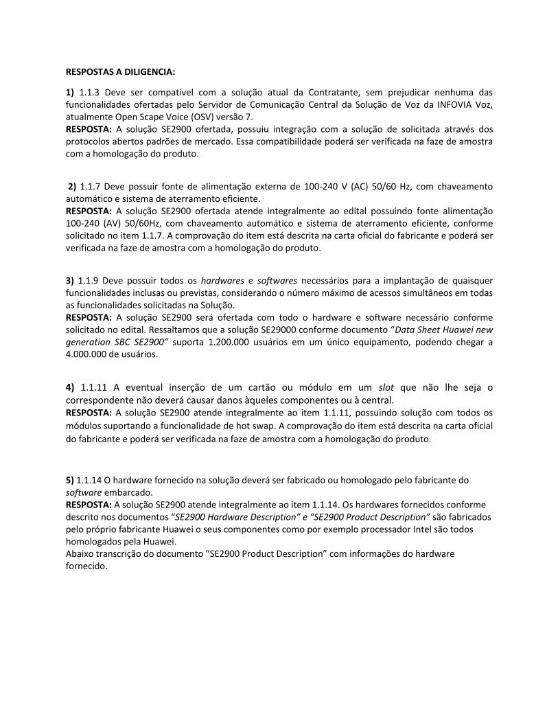
5) 1.1.14 O hardware fornecido na solução deverá ser fabricado ou homologado pelo fabricante do software embarcado. RESPOSTA: A solução SE2900 atende integralmente ao item 1.1.14. Os hardwares fornecidos conforme descrito nos documentos “SE2900 Hardware Description” e “SE2900 Product Description” são fabricados pelo próprio fabricante Huawei o seus componentes como por exemplo processador Intel são todos homologados pela Huawei. Abaixo transcrição do documento “SE2900 Product Description” com informações do hardware fornecido.
The SE2900 uses the F8002 subrack (3U high) and six slots, as shown in 0, 0, and Erro! Fonte de
referência não encontrada.. OMUs must be inserted in slots 2 and 5, SPUs must be inserted in slots 1, 3,
4, and 6, and VPUs must be inserted in slots 1, 3, 4, and 6.
Appearance
Front view
A comprovação do item está descrita na carta oficial do fabricante e poderá ser verificada na faze de amostra com a homologação do produto.
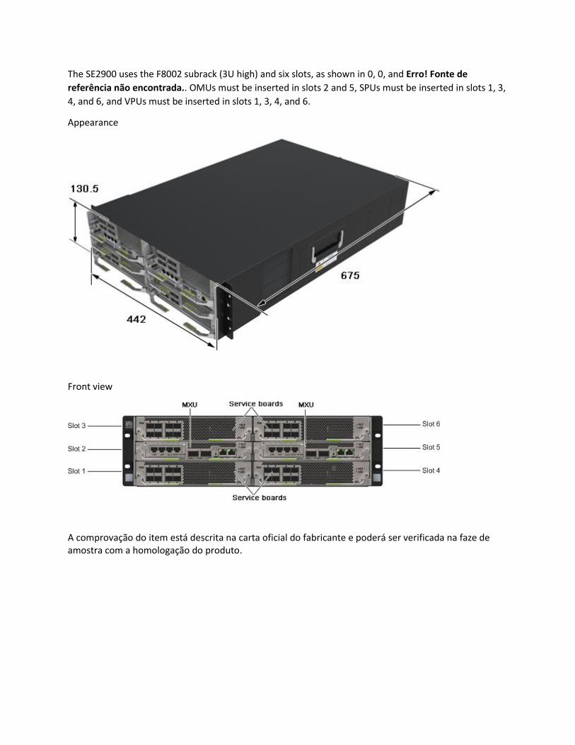
6) 1.1.16 Compatibilidade com soluções de telefonia atualmente utilizadas na INFOVIA, especialmente as informadas neste Anexo I ao Termo de Referência. RESPOSTA: A solução SE2900 ofertada, possuiu integração com a solução de solicitada através dos protocolos abertos padrões de mercado. Essa compatibilidade poderá ser verificada na faze de amostra com a homologação do produto. 7) 1.5.1 O hardware deve possuir, no mínimo, 500 (quinhentos) GB de HD para logs e CDR; tal recurso pode ser ofertado com redirecionamento de logs para um servidor externo, desde que fornecido pela Contratada, ou ponto de armazenamento externo. RESPOSTA: A solução é composta e será entregue com 02(dois) módulos MXU que possui 01(um) Hard
disks de 600(seiscentos) GB em cada modulo MXU. Ou seja, serão ofertados 04(quatro) hard disks de
600GB para a solução.
Abaixo transcrição do documento “SE2900 Hardware Description”:
1.7 MXU
The multi-function switch units (MXUs) exchange service plane data and provide ports for eFabric
interface cascading.
Describes the components of the MXUA0
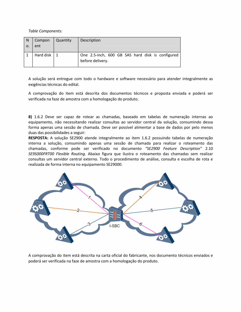
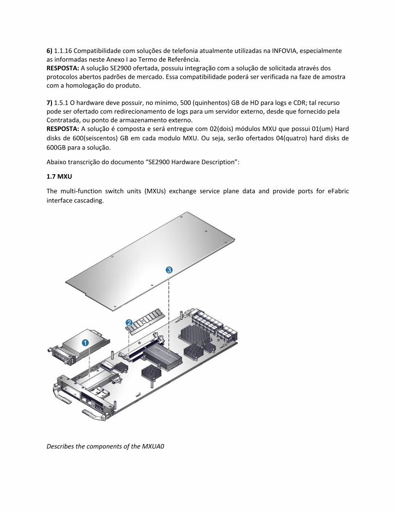
Table Components:
N
o.
Compon
ent
Quantity Description
1 Hard disk 1 One 2.5-inch, 600 GB SAS hard disk is configured
before delivery.
A solução será entregue com todo o hardware e software necessário para atender integralmente as
exigências técnicas do edital.
A comprovação do item está descrita dos documentos técnicos e proposta enviada e poderá ser
verificada na faze de amostra com a homologação do produto.
8) 1.6.2 Deve ser capaz de rotear as chamadas, baseado em tabelas de numeração internas ao equipamento, não necessitando realizar consultas ao servidor central da solução, consumindo dessa forma apenas uma sessão de chamada. Deve ser possível alimentar a base de dados por pelo menos duas das possibilidades a seguir: RESPOSTA: A solução SE2900 atende integralmente ao item 1.6.2 possuindo tabelas de numeração interna a solução, consumindo apenas uma sessão de chamada para realizar o roteamento das chamadas, conforme pode ser verificado no documento “SE2900 Feature Description” 2.10 SE9S000FRT00 Flexible Routing. Abaixo figura que ilustra o roteamento das chamadas sem realizar consultas um servidor central externo. Todo o procedimento de análise, consulta e escolha de rota e realizada de forma interna no equipamento SE29000.
A comprovação do item está descrita na carta oficial do fabricante, nos documento técnicos enviados e
poderá ser verificada na faze de amostra com a homologação do produto.
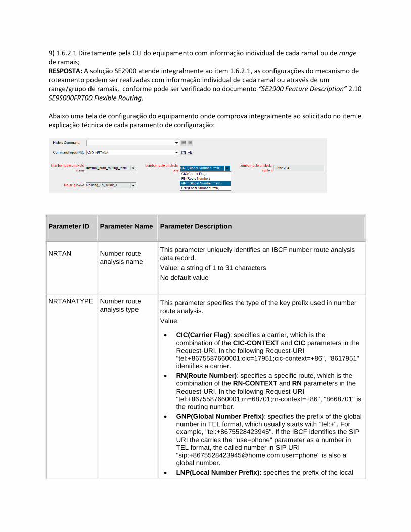
9) 1.6.2.1 Diretamente pela CLI do equipamento com informação individual de cada ramal ou de range de ramais; RESPOSTA: A solução SE2900 atende integralmente ao item 1.6.2.1, as configurações do mecanismo de roteamento podem ser realizadas com informação individual de cada ramal ou através de um range/grupo de ramais, conforme pode ser verificado no documento “SE2900 Feature Description” 2.10 SE9S000FRT00 Flexible Routing. Abaixo uma tela de configuração do equipamento onde comprova integralmente ao solicitado no item e explicação técnica de cada paramento de configuração:
Parameter ID Parameter Name Parameter Description
NRTAN Number route
analysis name
This parameter uniquely identifies an IBCF number route analysis
data record.
Value: a string of 1 to 31 characters
No default value
NRTANATYPE Number route
analysis type This parameter specifies the type of the key prefix used in number
route analysis.
Value:
CIC(Carrier Flag): specifies a carrier, which is the combination of the CIC-CONTEXT and CIC parameters in the Request-URI. In the following Request-URI "tel:+8675587660001;cic=17951;cic-context=+86", "8617951" identifies a carrier.
RN(Route Number): specifies a specific route, which is the combination of the RN-CONTEXT and RN parameters in the Request-URI. In the following Request-URI "tel:+8675587660001;rn=68701;rn-context=+86", "8668701" is the routing number.
GNP(Global Number Prefix): specifies the prefix of the global number in TEL format, which usually starts with "tel:+". For example, "tel:+8675528423945". If the IBCF identifies the SIP URI the carries the "use=phone" parameter as a number in TEL format, the called number in SIP URI "sip:[email protected];user=phone" is also a global number.
LNP(Local Number Prefix): specifies the prefix of the local
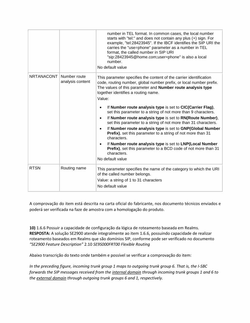
number in TEL format. In common cases, the local number starts with "tel:" and does not contain any plus (+) sign. For example, "tel:28423945". If the IBCF identifies the SIP URI the carries the "use=phone" parameter as a number in TEL format, the called number in SIP URI "sip:[email protected];user=phone" is also a local number.
No default value
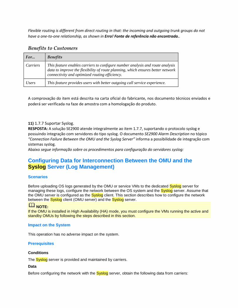
NRTANACONT Number route
analysis content This parameter specifies the content of the carrier identification
code, routing number, global number prefix, or local number prefix.
The values of this parameter and Number route analysis type
together identifies a routing name.
Value:
If Number route analysis type is set to CIC(Carrier Flag), set this parameter to a string of not more than 9 characters.
If Number route analysis type is set to RN(Route Number), set this parameter to a string of not more than 31 characters.
If Number route analysis type is set to GNP(Global Number Prefix), set this parameter to a string of not more than 31 characters.
If Number route analysis type is set to LNP(Local Number Prefix), set this parameter to a BCD code of not more than 31 characters.
No default value
RTSN Routing name This parameter specifies the name of the category to which the URI
of the called number belongs.
Value: a string of 1 to 31 characters
No default value
A comprovação do item está descrita na carta oficial do fabricante, nos documento técnicos enviados e
poderá ser verificada na faze de amostra com a homologação do produto.
10) 1.6.6 Possuir a capacidade de configuração da lógica de roteamento baseada em Realms. RESPOSTA: A solução SE2900 atende integralmente ao item 1.6.6, possuindo capacidade de realizar roteamento baseados em Realms que são domínios SIP, conforme pode ser verificado no documento “SE2900 Feature Description” 2.10 SE9S000FRT00 Flexible Routing Abaixo transcrição do texto onde também e possível se verificar a comprovação do item: In the preceding figure, incoming trunk group 1 maps to outgoing trunk group 6. That is, the I-SBC
forwards the SIP messages received from the internal domain through incoming trunk groups 1 and 6 to
the external domain through outgoing trunk groups 6 and 1, respectively.
Flexible routing is different from direct routing in that: the incoming and outgoing trunk groups do not
have a one-to-one relationship, as shown in Erro! Fonte de referência não encontrada..
Benefits to Customers
For... Benefits
Carriers This feature enables carriers to configure number analysis and route analysis
data to improve the flexibility of route planning, which ensures better network
connectivity and optimized routing efficiency.
Users This feature provides users with better outgoing call service experience.
A comprovação do item está descrita na carta oficial do fabricante, nos documento técnicos enviados e
poderá ser verificada na faze de amostra com a homologação do produto.
11) 1.7.7 Suportar Syslog. RESPOSTA: A solução SE2900 atende integralmente ao item 1.7.7, suportando o protocolo syslog e possuindo integração com servidores do tipo syslog. O documento SE2900 Alarm Description no tópico “Connection Failure Between the OMU and the Syslog Server” informa a possibilidade de integração com sistemas syslog. Abaixo segue informação sobre os procedimentos para configuração do servidores syslog:
Configuring Data for Interconnection Between the OMU and the Syslog Server (Log Management)
Scenarios
Before uploading OS logs generated by the OMU or service VMs to the dedicated Syslog server for managing these logs, configure the network between the OS system and the Syslog server. Assume that the OMU server is configured as the Syslog client. This section describes how to configure the network between the Syslog client (OMU server) and the Syslog server.
NOTE: If the OMU is installed in High Availability (HA) mode, you must configure the VMs running the active and standby OMUs by following the steps described in this section.
Impact on the System
This operation has no adverse impact on the system.
Prerequisites
Conditions
The Syslog server is provided and maintained by carriers.
Data
Before configuring the network with the Syslog server, obtain the following data from carriers:
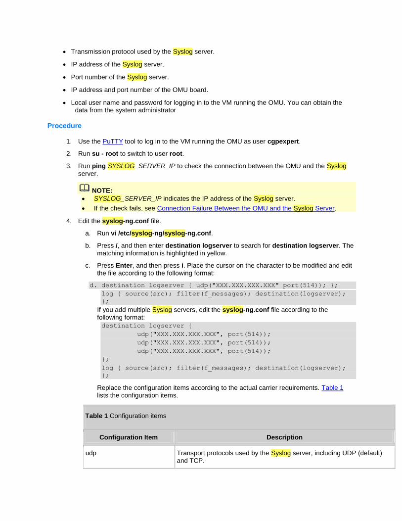
Transmission protocol used by the Syslog server.
IP address of the Syslog server.
Port number of the Syslog server.
IP address and port number of the OMU board.
Local user name and password for logging in to the VM running the OMU. You can obtain the data from the system administrator
Procedure
1. Use the PuTTY tool to log in to the VM running the OMU as user cgpexpert.
2. Run su - root to switch to user root.
3. Run ping SYSLOG_SERVER_IP to check the connection between the OMU and the Syslog server.
NOTE:
SYSLOG_SERVER_IP indicates the IP address of the Syslog server.
If the check fails, see Connection Failure Between the OMU and the Syslog Server.
4. Edit the syslog-ng.conf file.
a. Run vi /etc/syslog-ng/syslog-ng.conf.
b. Press /, and then enter destination logserver to search for destination logserver. The matching information is highlighted in yellow.
c. Press Enter, and then press i. Place the cursor on the character to be modified and edit the file according to the following format:
d. destination logserver { udp("XXX.XXX.XXX.XXX" port(514)); };
log { source(src); filter(f_messages); destination(logserver);
};
If you add multiple Syslog servers, edit the syslog-ng.conf file according to the following format:
destination logserver {
udp("XXX.XXX.XXX.XXX", port(514));
udp("XXX.XXX.XXX.XXX", port(514));
udp("XXX.XXX.XXX.XXX", port(514));
};
log { source(src); filter(f_messages); destination(logserver);
};
Replace the configuration items according to the actual carrier requirements. Table 1 lists the configuration items.
Table 1 Configuration items
Configuration Item Description
udp Transport protocols used by the Syslog server, including UDP (default) and TCP.
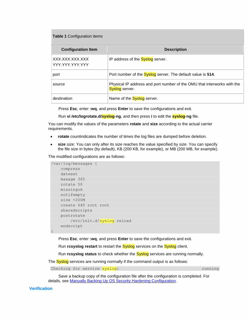
Table 1 Configuration items
Configuration Item Description
XXX.XXX.XXX.XXX
YYY.YYY.YYY.YYY
IP address of the Syslog server.
port Port number of the Syslog server. The default value is 514.
source Physical IP address and port number of the OMU that interworks with the Syslog server.
destination Name of the Syslog server.
Press Esc, enter :wq, and press Enter to save the configurations and exit.
Run vi /etc/logrotate.d/syslog-ng, and then press i to edit the syslog-ng file.
You can modify the values of the parameters rotate and size according to the actual carrier requirements.
rotate countindicates the number of times the log files are dumped before deletion.
size size: You can only after its size reaches the value specified by size. You can specify the file size in bytes (by default), KB (200 KB, for example), or MB (200 MB, for example).
The modified configurations are as follows:
/var/log/messages {
compress
dateext
maxage 365
rotate 50
missingok
notifempty
size +200M
create 640 root root
sharedscripts
postrotate
/etc/init.d/syslog reload
endscript
}
Press Esc, enter :wq, and press Enter to save the configurations and exit.
Run rcsyslog restart to restart the Syslog services on the Syslog client.
Run rcsyslog status to check whether the Syslog services are running normally.
The Syslog services are running normally if the command output is as follows:
Checking for service syslog: running
Save a backup copy of the configuration file after the configuration is completed. For details, see Manually Backing Up OS Security Hardening Configuration.
Verification
To verify the Syslog server and Syslog client connection, perform the following steps:
1. Run tail -f /var/log/messages on the Syslog client and check the last line of the messages file.
2. Open the /var/log/messages file on the Syslog server. If the content contains the last line of the messages file generated on the Syslog client, you can infer that the interworking is correctly configured.
A comprovação do item está descrita na carta oficial do fabricante, nos documento técnicos enviados e
poderá ser verificada na faze de amostra com a homologação do produto
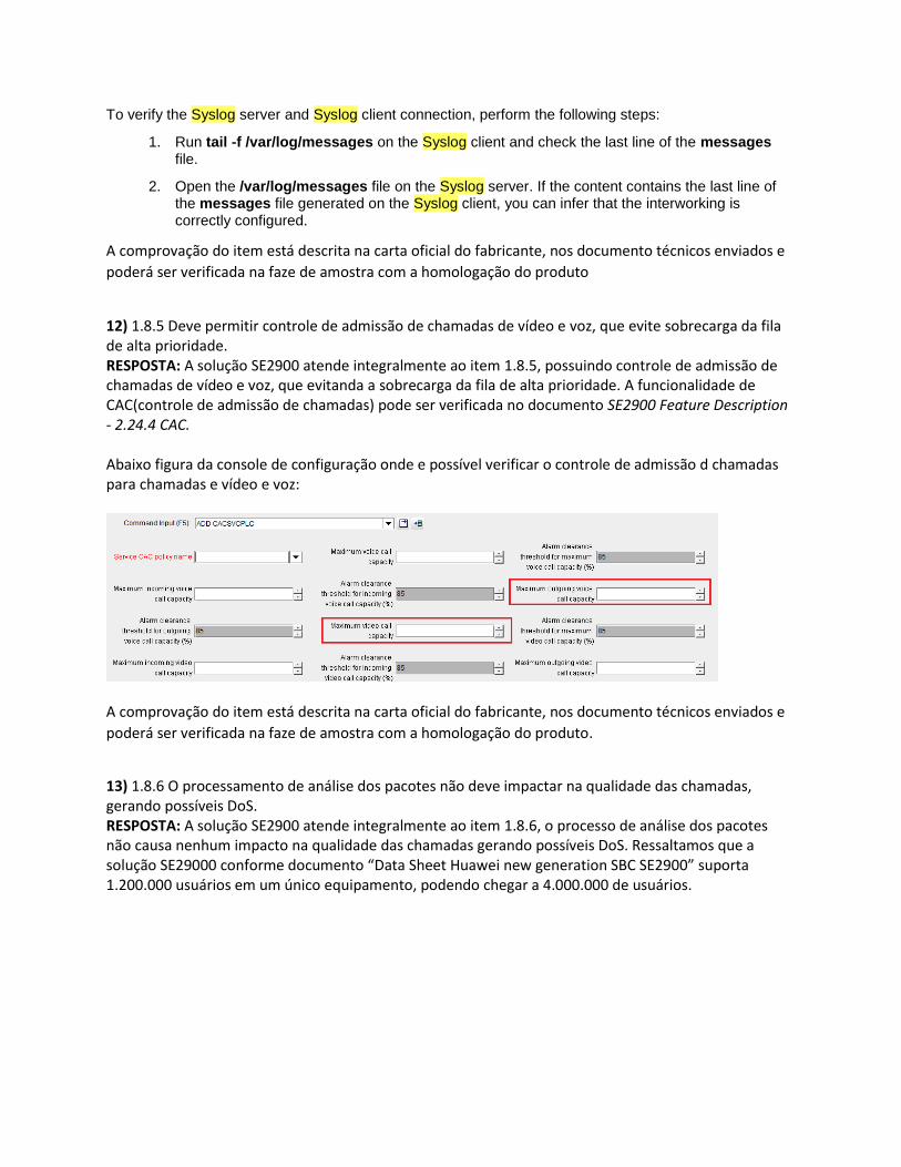
12) 1.8.5 Deve permitir controle de admissão de chamadas de vídeo e voz, que evite sobrecarga da fila de alta prioridade. RESPOSTA: A solução SE2900 atende integralmente ao item 1.8.5, possuindo controle de admissão de chamadas de vídeo e voz, que evitanda a sobrecarga da fila de alta prioridade. A funcionalidade de CAC(controle de admissão de chamadas) pode ser verificada no documento SE2900 Feature Description - 2.24.4 CAC. Abaixo figura da console de configuração onde e possível verificar o controle de admissão d chamadas para chamadas e vídeo e voz:
A comprovação do item está descrita na carta oficial do fabricante, nos documento técnicos enviados e
poderá ser verificada na faze de amostra com a homologação do produto.
13) 1.8.6 O processamento de análise dos pacotes não deve impactar na qualidade das chamadas, gerando possíveis DoS. RESPOSTA: A solução SE2900 atende integralmente ao item 1.8.6, o processo de análise dos pacotes não causa nenhum impacto na qualidade das chamadas gerando possíveis DoS. Ressaltamos que a solução SE29000 conforme documento “Data Sheet Huawei new generation SBC SE2900” suporta 1.200.000 usuários em um único equipamento, podendo chegar a 4.000.000 de usuários.
14) 1.8.18 Deve ser do tipo Stateful Firewall Inspection. RESPOSTA: A solução SE2900 atende integralmente ao item 1.8.18, sendo um equipamento do tipo Statefull com funcionalidades de Firewall inspection conforme solicitado no edital. A comprovação do item foi demonstrada através de funcionalidade de IDS(intrusion detection system) que características de soluções do tipo Stateful firewall inspection. Pode ser comprovado também outras funcionalidades de firewall statefull no documento SE2900 Feature Description- 2.24 SE9SBSECSW00 Security Enhancement Function. A comprovação do item está descrita na carta oficial do fabricante, nos documento técnicos enviados e
poderá ser verificada na faze de amostra com a homologação do produto.
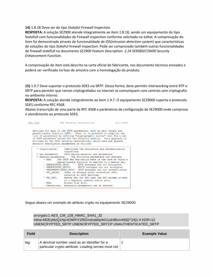
15) 1.9.7 Deve suportar o protocolo SDES via SRTP. Dessa forma, deve permitir Interworking entre RTP e SRTP para permitir que ramais criptografados na internet se comuniquem com centrais sem criptografia no ambiente interno. RESPOSTA: A solução atende integralmente ao item 1.9.7. O equipamento SE29000 suporta o protocolo SDES conforme RFC 4568. Abaixo transcrição de uma parte da RFC 4568 e parâmetros de configuração do SE29000 onde comprova o atendimento ao protocolo SDES.
Segue abaixo um exemplo do atributo crypto no equipamento SE29000.
a=crypto:1 AES_CM_128_HMAC_SHA1_32
inline:MDEyMzQ1Njc4OWFiY2RlZmdoaWprbG1ub3BxcnN0|2^24|1:4 KDR=12
UNENCRYPTED_SRTP UNENCRYPTED_SRTCP UNAUTHENTICATED_SRTP
Field Description Example Value
tag A decimal number used as an identifier for a
particular crypto attribute. Leading zeroes must not
1
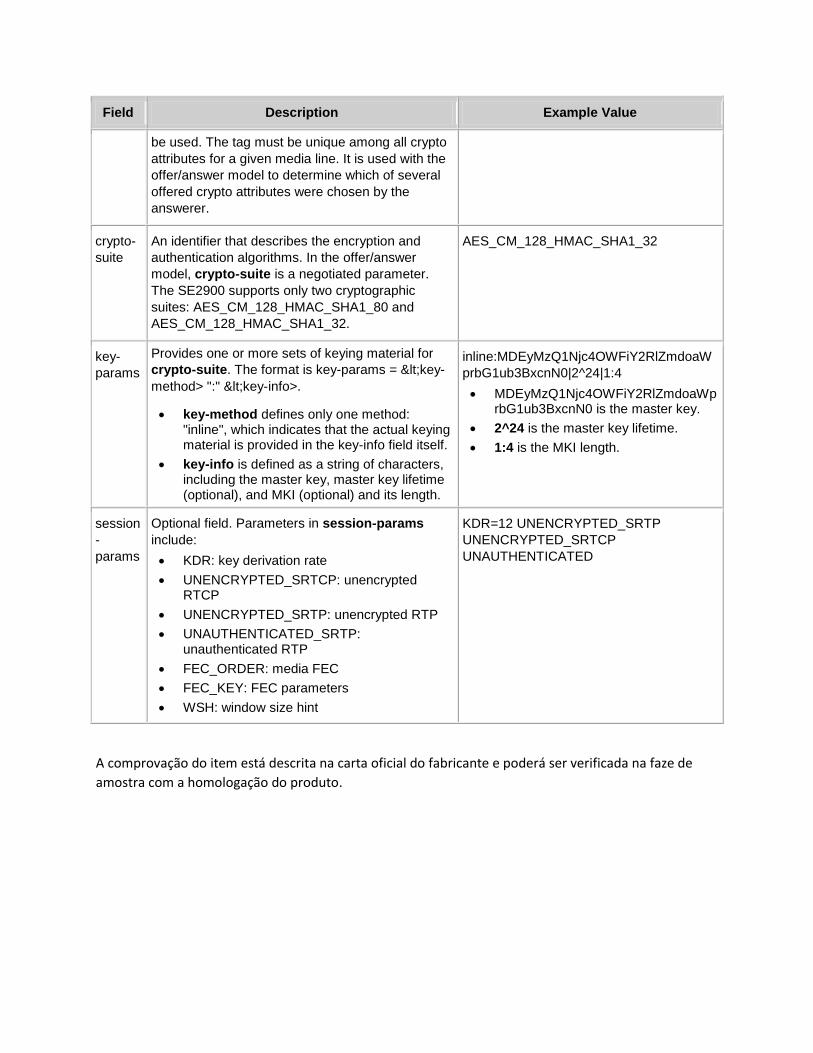
Field Description Example Value
be used. The tag must be unique among all crypto
attributes for a given media line. It is used with the
offer/answer model to determine which of several
offered crypto attributes were chosen by the
answerer.
crypto-
suite
An identifier that describes the encryption and
authentication algorithms. In the offer/answer
model, crypto-suite is a negotiated parameter.
The SE2900 supports only two cryptographic
suites: AES_CM_128_HMAC_SHA1_80 and
AES_CM_128_HMAC_SHA1_32.
AES_CM_128_HMAC_SHA1_32
key-
params
Provides one or more sets of keying material for
crypto-suite. The format is key-params = <key-
method> ":" <key-info>.
key-method defines only one method: "inline", which indicates that the actual keying material is provided in the key-info field itself.
key-info is defined as a string of characters, including the master key, master key lifetime (optional), and MKI (optional) and its length.
inline:MDEyMzQ1Njc4OWFiY2RlZmdoaW
prbG1ub3BxcnN0|2^24|1:4
MDEyMzQ1Njc4OWFiY2RlZmdoaWprbG1ub3BxcnN0 is the master key.
2^24 is the master key lifetime.
1:4 is the MKI length.
session
-
params
Optional field. Parameters in session-params
include:
KDR: key derivation rate
UNENCRYPTED_SRTCP: unencrypted RTCP
UNENCRYPTED_SRTP: unencrypted RTP
UNAUTHENTICATED_SRTP: unauthenticated RTP
FEC_ORDER: media FEC
FEC_KEY: FEC parameters
WSH: window size hint
KDR=12 UNENCRYPTED_SRTP
UNENCRYPTED_SRTCP
UNAUTHENTICATED
A comprovação do item está descrita na carta oficial do fabricante e poderá ser verificada na faze de
amostra com a homologação do produto.
16) 1.9.10 Definir as portas que serão utilizadas na comunicação pelos protocolos de sinalização e liberá-las apenas para os endpoints em questão durante o período da comunicação. RESPOSTA: A solução SE2900 atende integralmente ao item 1.9.10. Os conceitos e métodos utilizados para liberação das portas de forma segura da solução pode ser encontrada no documento SE2900 Feature Description - 1.1.3 SIP Call - Session timer, 1.2.7 Flow Control, 2.24 SE9SBSECSW00 Security Enhancement Function - 2.24.4 CAC. Abaixo transcrevemos parte do configuração do recurso A-BCF(Access Border Control Function): Configuring A-BCF Data Contents 3.3.3.5.1 Configuring A-BCF Data 3.3.3.5.1 Configuring A-BCF Data
1.1 Scenarios
When the SE2900 is deployed between the access and core networks and serves as an A-SBC for
signaling proxy, A-BCF data must be configured.
A-BCF data configuration includes the following:
Configure the access-side signaling address and well-known port for signaling exchange between the SE2900 and UEs. The access-side signaling address name is for reference by ADD SIPAN.
Configure the core-side signaling address and signaling address group for signaling exchange between the SE2900 and core servers. The core-side signaling address group name is for reference by ADD ART and ADD PCSCF.
UE A and UE B are registered with the same SBC, and UE Z is registered with another server.
Figure 1 shows the categories and functions of A-BCF data during the registration of UE A and
the call between UE A and UE Z. Figure 2 shows the categories and functions of A-BCF data
during the registration of UE A and UE B and the call between UE A and UE B.

1.2 Prerequisites
Conditions
You have administrator rights.
You have logged in to the SE2900.
Software Installation is complete.
Data
Table 1 lists the A-BCF data to be planned.
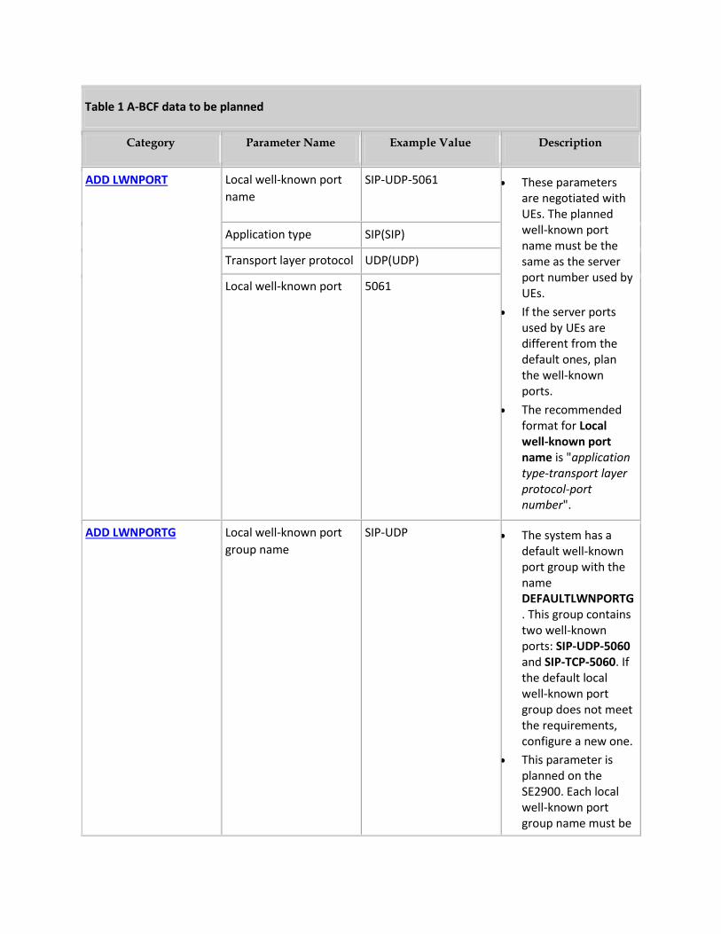
Table 1 A-BCF data to be planned
Category Parameter Name Example Value Description
ADD LWNPORT Local well-known port
name
SIP-UDP-5061 These parameters are negotiated with UEs. The planned well-known port name must be the same as the server port number used by UEs.
If the server ports used by UEs are different from the default ones, plan the well-known ports.
The recommended format for Local well-known port name is "application type-transport layer protocol-port number".
Application type SIP(SIP)
Transport layer protocol UDP(UDP)
Local well-known port 5061
ADD LWNPORTG Local well-known port
group name
SIP-UDP The system has a default well-known port group with the name DEFAULTLWNPORTG. This group contains two well-known ports: SIP-UDP-5060 and SIP-TCP-5060. If the default local well-known port group does not meet the requirements, configure a new one.
This parameter is planned on the SE2900. Each local well-known port group name must be
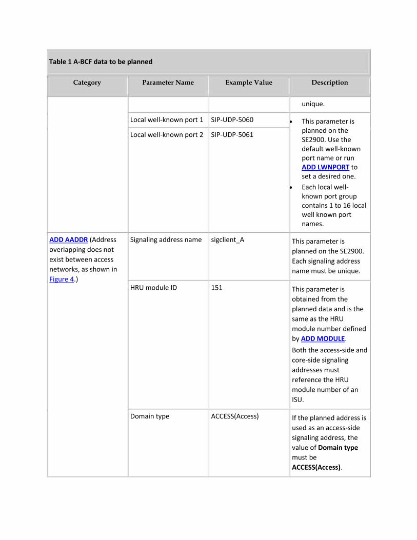
Table 1 A-BCF data to be planned
Category Parameter Name Example Value Description
unique.
Local well-known port 1 SIP-UDP-5060 This parameter is planned on the SE2900. Use the default well-known port name or run ADD LWNPORT to set a desired one.
Each local well-known port group contains 1 to 16 local well known port names.
Local well-known port 2 SIP-UDP-5061
ADD AADDR (Address
overlapping does not
exist between access
networks, as shown in
Figure 4.)
Signaling address name sigclient_A This parameter is
planned on the SE2900.
Each signaling address
name must be unique.
HRU module ID 151 This parameter is
obtained from the
planned data and is the
same as the HRU
module number defined
by ADD MODULE.
Both the access-side and
core-side signaling
addresses must
reference the HRU
module number of an
ISU.
Domain type ACCESS(Access) If the planned address is
used as an access-side
signaling address, the
value of Domain type
must be
ACCESS(Access).
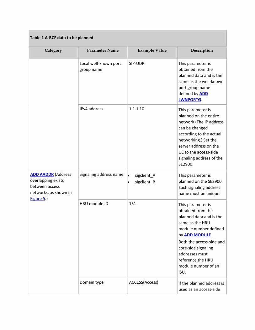
Table 1 A-BCF data to be planned
Category Parameter Name Example Value Description
Local well-known port
group name
SIP-UDP This parameter is
obtained from the
planned data and is the
same as the well-known
port group name
defined by ADD
LWNPORTG.
IPv4 address 1.1.1.10 This parameter is
planned on the entire
network (The IP address
can be changed
according to the actual
networking.) Set the
server address on the
UE to the access-side
signaling address of the
SE2900.
ADD AADDR (Address
overlapping exists
between access
networks, as shown in
Figure 5.)
Signaling address name sigclient_A
sigclient_B
This parameter is
planned on the SE2900.
Each signaling address
name must be unique.
HRU module ID 151 This parameter is
obtained from the
planned data and is the
same as the HRU
module number defined
by ADD MODULE.
Both the access-side and
core-side signaling
addresses must
reference the HRU
module number of an
ISU.
Domain type ACCESS(Access) If the planned address is
used as an access-side
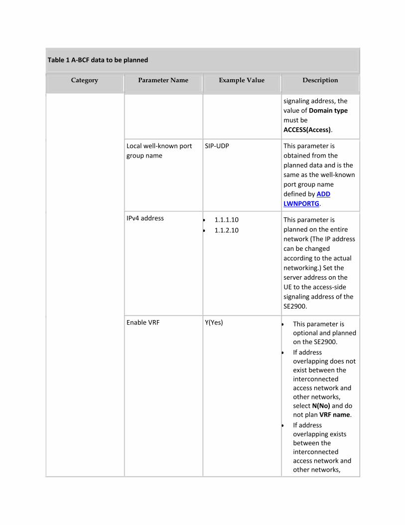
Table 1 A-BCF data to be planned
Category Parameter Name Example Value Description
signaling address, the
value of Domain type
must be
ACCESS(Access).
Local well-known port
group name
SIP-UDP This parameter is
obtained from the
planned data and is the
same as the well-known
port group name
defined by ADD
LWNPORTG.
IPv4 address 1.1.1.10
1.1.2.10
This parameter is
planned on the entire
network (The IP address
can be changed
according to the actual
networking.) Set the
server address on the
UE to the access-side
signaling address of the
SE2900.
Enable VRF Y(Yes) This parameter is optional and planned on the SE2900.
If address overlapping does not exist between the interconnected access network and other networks, select N(No) and do not plan VRF name.
If address overlapping exists between the interconnected access network and other networks,
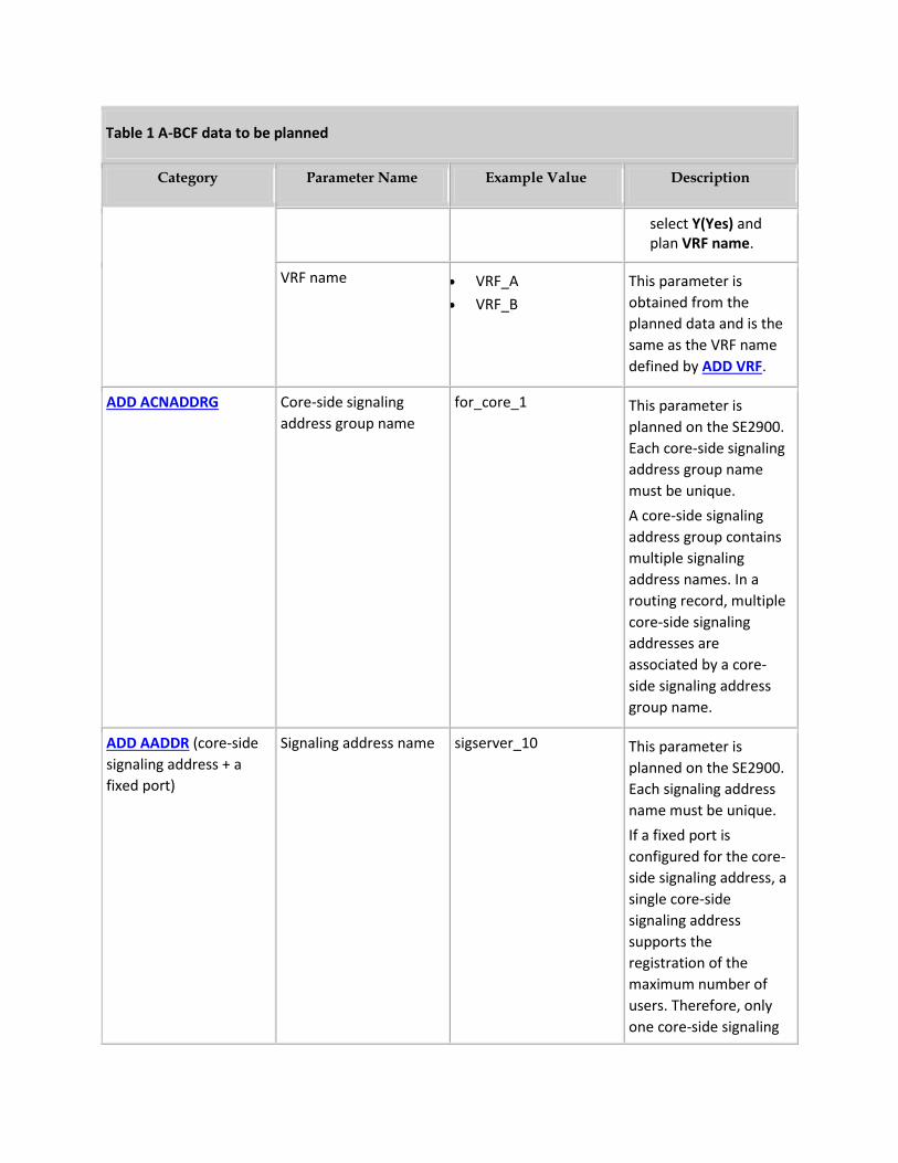
Table 1 A-BCF data to be planned
Category Parameter Name Example Value Description
select Y(Yes) and plan VRF name.
VRF name VRF_A
VRF_B
This parameter is
obtained from the
planned data and is the
same as the VRF name
defined by ADD VRF.
ADD ACNADDRG Core-side signaling
address group name
for_core_1 This parameter is
planned on the SE2900.
Each core-side signaling
address group name
must be unique.
A core-side signaling
address group contains
multiple signaling
address names. In a
routing record, multiple
core-side signaling
addresses are
associated by a core-
side signaling address
group name.
ADD AADDR (core-side
signaling address + a
fixed port)
Signaling address name sigserver_10 This parameter is
planned on the SE2900.
Each signaling address
name must be unique.
If a fixed port is
configured for the core-
side signaling address, a
single core-side
signaling address
supports the
registration of the
maximum number of
users. Therefore, only
one core-side signaling
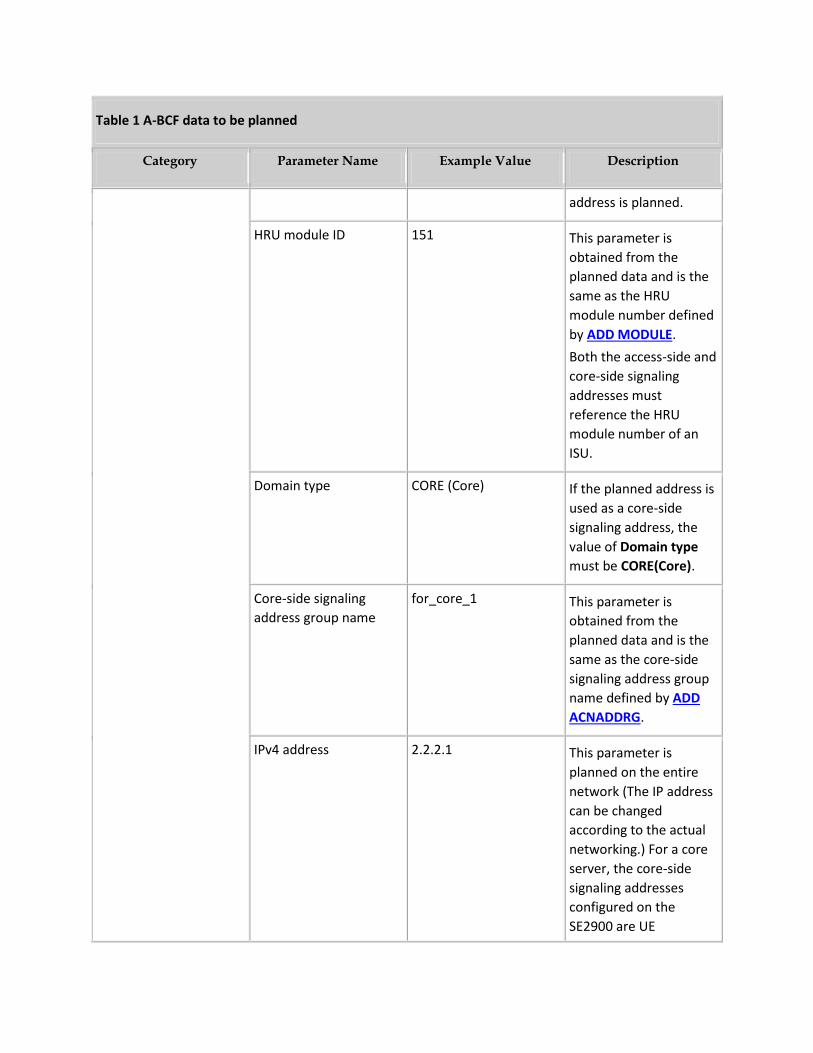
Table 1 A-BCF data to be planned
Category Parameter Name Example Value Description
address is planned.
HRU module ID 151 This parameter is
obtained from the
planned data and is the
same as the HRU
module number defined
by ADD MODULE.
Both the access-side and
core-side signaling
addresses must
reference the HRU
module number of an
ISU.
Domain type CORE (Core) If the planned address is
used as a core-side
signaling address, the
value of Domain type
must be CORE(Core).
Core-side signaling
address group name
for_core_1 This parameter is
obtained from the
planned data and is the
same as the core-side
signaling address group
name defined by ADD
ACNADDRG.
IPv4 address 2.2.2.1 This parameter is
planned on the entire
network (The IP address
can be changed
according to the actual
networking.) For a core
server, the core-side
signaling addresses
configured on the
SE2900 are UE
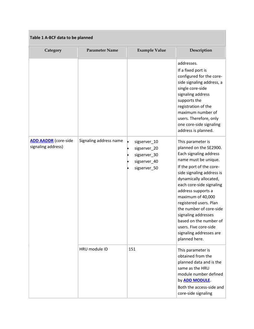
Table 1 A-BCF data to be planned
Category Parameter Name Example Value Description
addresses.
If a fixed port is
configured for the core-
side signaling address, a
single core-side
signaling address
supports the
registration of the
maximum number of
users. Therefore, only
one core-side signaling
address is planned.
ADD AADDR (core-side
signaling address)
Signaling address name sigserver_10
sigserver_20
sigserver_30
sigserver_40
sigserver_50
This parameter is
planned on the SE2900.
Each signaling address
name must be unique.
If the port of the core-
side signaling address is
dynamically allocated,
each core-side signaling
address supports a
maximum of 40,000
registered users. Plan
the number of core-side
signaling addresses
based on the number of
users. Five core-side
signaling addresses are
planned here.
HRU module ID 151 This parameter is
obtained from the
planned data and is the
same as the HRU
module number defined
by ADD MODULE.
Both the access-side and
core-side signaling
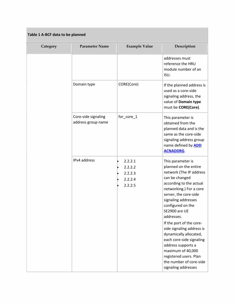
Table 1 A-BCF data to be planned
Category Parameter Name Example Value Description
addresses must
reference the HRU
module number of an
ISU.
Domain type CORE(Core) If the planned address is
used as a core-side
signaling address, the
value of Domain type
must be CORE(Core).
Core-side signaling
address group name
for_core_1 This parameter is
obtained from the
planned data and is the
same as the core-side
signaling address group
name defined by ADD
ACNADDRG.
IPv4 address 2.2.2.1
2.2.2.2
2.2.2.3
2.2.2.4
2.2.2.5
This parameter is
planned on the entire
network (The IP address
can be changed
according to the actual
networking.) For a core
server, the core-side
signaling addresses
configured on the
SE2900 are UE
addresses.
If the port of the core-
side signaling address is
dynamically allocated,
each core-side signaling
address supports a
maximum of 40,000
registered users. Plan
the number of core-side
signaling addresses
Table 1 A-BCF data to be planned
Category Parameter Name Example Value Description
based on the number of
users. Five core-side
signaling addresses are
planned here.
Core-side signaling
addresses with
dynamically allocated
ports are recommended
if an external P-CSCF is
deployed.
1.3 Workflow
Figure 3 shows the index mappings for A-BCF data configuration.
Figure 3 Reference relationships for A-BCF data configuration
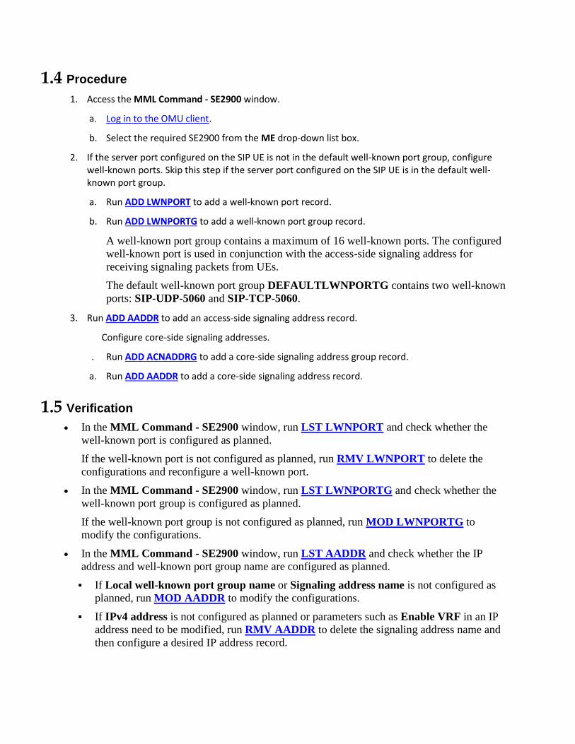
1.4 Procedure
1. Access the MML Command - SE2900 window.
a. Log in to the OMU client.
b. Select the required SE2900 from the ME drop-down list box.
2. If the server port configured on the SIP UE is not in the default well-known port group, configure well-known ports. Skip this step if the server port configured on the SIP UE is in the default well-known port group.
a. Run ADD LWNPORT to add a well-known port record.
b. Run ADD LWNPORTG to add a well-known port group record.
A well-known port group contains a maximum of 16 well-known ports. The configured
well-known port is used in conjunction with the access-side signaling address for
receiving signaling packets from UEs.
The default well-known port group DEFAULTLWNPORTG contains two well-known
ports: SIP-UDP-5060 and SIP-TCP-5060.
3. Run ADD AADDR to add an access-side signaling address record.
Configure core-side signaling addresses.
. Run ADD ACNADDRG to add a core-side signaling address group record.
a. Run ADD AADDR to add a core-side signaling address record.
1.5 Verification
In the MML Command - SE2900 window, run LST LWNPORT and check whether the
well-known port is configured as planned.
If the well-known port is not configured as planned, run RMV LWNPORT to delete the
configurations and reconfigure a well-known port.
In the MML Command - SE2900 window, run LST LWNPORTG and check whether the
well-known port group is configured as planned.
If the well-known port group is not configured as planned, run MOD LWNPORTG to
modify the configurations.
In the MML Command - SE2900 window, run LST AADDR and check whether the IP
address and well-known port group name are configured as planned.
If Local well-known port group name or Signaling address name is not configured as
planned, run MOD AADDR to modify the configurations.
If IPv4 address is not configured as planned or parameters such as Enable VRF in an IP
address need to be modified, run RMV AADDR to delete the signaling address name and
then configure a desired IP address record.
1.6 Example I: Core-side Signaling Address Is Configured with a Fixed Port and No Address Overlapping Exists
Task Description
Add the access-side signaling address, well-known port, and core-side signaling address for
accessing UEs on access network A. Table 1 shows details about the planned data, and Figure 4
shows the networking.
Figure 4 A-BCF networking diagram (core-side signaling address is configured with a fixed port and no
address overlapping exists)
Scripts
/*----------Configure data in the MML Command - SE2900 window on the OMU client.---------
-*/
/*If the server port configured on a SIP UE is not the default well-known port, configure a well-
known port. Otherwise, you do not need to add well-known ports.*/
ADD LWNPORT: LWNPORTNAME="SIP-UDP-5061", APPTYPE=SIP, TLPRO=UDP, PORT=5061;
/*If the server port configured on a SIP UE is not in the default well-known port group, add a
well-known port group. Otherwise, you do not need to add well-known port groups.*/
ADD LWNPORTG: LWNPORTGNAME="SIP-UDP", LWNPORTNAME1="SIP-UDP-5060",
LWNPORTNAME2="SIP-UDP-5061";
/*Add an access-side signaling address for UEs on access network A. If all server ports
configured on SIP UEs are in the default well-known port group, use the default well-known port
group DEFAULTLWNPORTG.*/
ADD AADDR: ADDRNAME="sigclient_A", HRUMID=151, DMT=ACCESS, LWNPORTGNAME="SIP-
UDP", IPV4="1.1.1.10", VRFFLAG=N;
/*Add a core-side signaling address group for UEs on access network A.*/
ADD ACNADDRG: ADDRGN="for_core_1";
/*Add a core-side signaling address. This IP address is used for the SE2900 to interwork with
core servers and specifies the signaling address converted from the source address of the packet
sent from a UE on access network A.*/
ADD AADDR: ADDRNAME="sigserver_10", HRUMID=151, DMT=CORE,
ADDRGN="for_core_1", IPV4="2.2.2.1", VRFFLAG=N;
1.7 Example II: Core-side Signaling Address Is Configured with a Dynamically Allocated Port and Address Overlapping Exists Between Access Networks
Task Description
Add the access-side signaling address, well-known port, and core-side signaling address for accessing
UEs on access networks A and B. Table 1 shows details about the planned data, and Figure 5 shows the
networking.
NOTE:
In the following example, address overlapping exists between access networks A and B.
Figure 5 A-BCF networking diagram (core-side signaling address is configured with a dynamically
allocated port and address overlapping exists between access networks)
Scripts
/*----------Configure data in the MML Command - SE2900 window on the OMU client.---------
-*/
/*If the server port configured on a SIP UE is not the default well-known port, configure a well-
known port. Otherwise, you do not need to add well-known ports.*/
ADD LWNPORT: LWNPORTNAME="SIP-UDP-5061", APPTYPE=SIP, TLPRO=UDP, PORT=5061;
/*If the server port configured on a SIP UE is not in the default well-known port group, add a
well-known port group. Otherwise, you do not need to add well-known port groups.*/
ADD LWNPORTG: LWNPORTGNAME="SIP-UDP", LWNPORTNAME1="SIP-UDP-5060",
LWNPORTNAME2="SIP-UDP-5061";
/*Add an access-side signaling address for UEs on access network A. If all server ports
configured on SIP UEs are in the default well-known port group, use the default well-known port
group DEFAULTLWNPORTG.*/
ADD AADDR: ADDRNAME="sigclient_A", HRUMID=151, DMT=ACCESS, LWNPORTGNAME="SIP-
UDP", IPV4="1.1.1.10", VRFFLAG=Y, VRFNAME="VRF_A";
/*Add an access-side signaling address for UEs on access network B. If all server ports
configured on SIP UEs are in the default well-known port group, use the default well-known port
group DEFAULTLWNPORTG.*/
ADD AADDR: ADDRNAME="sigclient_B", HRUMID=151, DMT=ACCESS, LWNPORTGNAME="SIP-
UDP", IPV4="1.1.2.10", VRFFLAG=Y, VRFNAME="VRF_B";
/*Add a core-side signaling address group for UEs on access networks A and B.*/
ADD ACNADDRG: ADDRGN="for_core_1";
/*Add a core-side signaling address. This IP address is used for the SE2900 to interwork with
core servers and specifies the signaling address converted from the source address of the packet
sent from a UE on access network A or B.*/
ADD AADDR: ADDRNAME="sigserver_10", HRUMID=151, DMT=CORE,
ADDRGN="for_core_1", IPV4="2.2.2.1", VRFFLAG=N;
ADD AADDR: ADDRNAME="sigserver_20", HRUMID=151, DMT=CORE,
ADDRGN="for_core_1", IPV4="2.2.2.2", VRFFLAG=N;
ADD AADDR: ADDRNAME="sigserver_30", HRUMID=151, DMT=CORE,
ADDRGN="for_core_1", IPV4="2.2.2.3", VRFFLAG=N;
ADD AADDR: ADDRNAME="sigserver_40", HRUMID=151, DMT=CORE,
ADDRGN="for_core_1", IPV4="2.2.2.4", VRFFLAG=N;
ADD AADDR: ADDRNAME="sigserver_50", HRUMID=151, DMT=CORE,
ADDRGN="for_core_1", IPV4="2.2.2.5", VRFFLAG=N;
A comprovação do item está descrita na carta oficial do fabricante e poderá ser verificada na faze de
amostra com a homologação do produto.
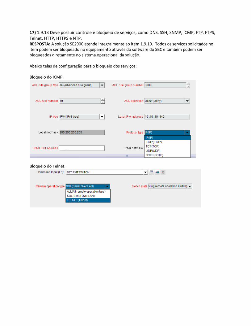
17) 1.9.13 Deve possuir controle e bloqueio de serviços, como DNS, SSH, SNMP, ICMP, FTP, FTPS, Telnet, HTTP, HTTPS e NTP. RESPOSTA: A solução SE2900 atende integralmente ao item 1.9.10. Todos os serviços solicitados no item podem ser bloqueado no equipamento através do software do SBC e também podem ser bloqueados diretamente no sistema operacional da solução. Abaixo telas de configuração para o bloqueio dos serviços: Bloqueio do ICMP:
Bloqueio do Telnet:
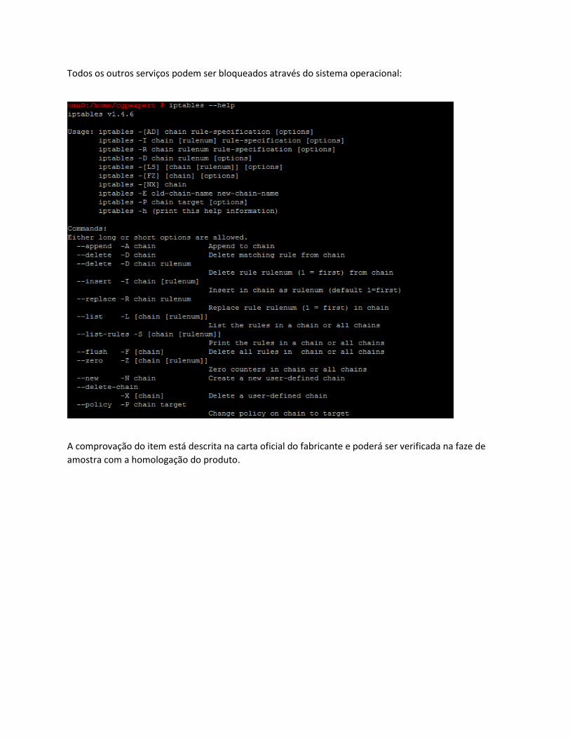
Todos os outros serviços podem ser bloqueados através do sistema operacional:
A comprovação do item está descrita na carta oficial do fabricante e poderá ser verificada na faze de
amostra com a homologação do produto.
18) 1.9.14 Deverá permitir o isolamento de tráfego entre redes da INFOVIA Voz com range de IP semelhantes, não sendo aceitas soluções para este item baseadas em virtualização de endpoints. RESPOSTA: A solução SE2900 atende integralmente ao item 1.9.14. O equipamento SE29000 permite isolar o trafego entre as diversas redes com range de IP semelhantes, essa funcionalidade é chamada de Address Overlapping. Abaixo transcrição de parte do texto do documento SE2900 Product Description - 4.3.4 Address Overlapping
1.7.1 Address Overlapping
Virtual Routing and Forwarding (VRF) is a technology that allows multiple instances of a routing table to
coexist on the SE2900, which is used to implement address overlapping. Packets are sent and received
independently in each VRF instance. Routing instances are independent of each other, with their own
routing entries, interfaces, and IP addresses. The overlapping IP addresses/segments can be used in
different routing instances without conflicting with each other.
The SE2900 allows access network addresses to overlap with each other, core network addresses to
overlap with each other, and access network addresses and core network addresses to overlap with each
other. Address overlapping implements the sharing of IP addresses/segments and simplifies the service
and application configurations on different access networks. Address overlapping saving the IP address,
and much more compatible with live network.
Overlapping Between Access Network Addresses
Two access networks with overlapping IP addresses/segments connect to the same SE2900. Figure 1-1
shows the networking for overlapping between access network addresses.
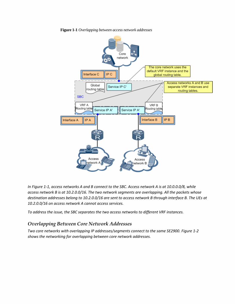
Figure 1-1 Overlapping between access network addresses
In Figure 1-1, access networks A and B connect to the SBC. Access network A is at 10.0.0.0/8, while
access network B is at 10.2.0.0/16. The two network segments are overlapping. All the packets whose
destination addresses belong to 10.2.0.0/16 are sent to access network B through interface B. The UEs at
10.2.0.0/16 on access network A cannot access services.
To address the issue, the SBC separates the two access networks to different VRF instances.
Overlapping Between Core Network Addresses
Two core networks with overlapping IP addresses/segments connect to the same SE2900. Figure 1-2
shows the networking for overlapping between core network addresses.
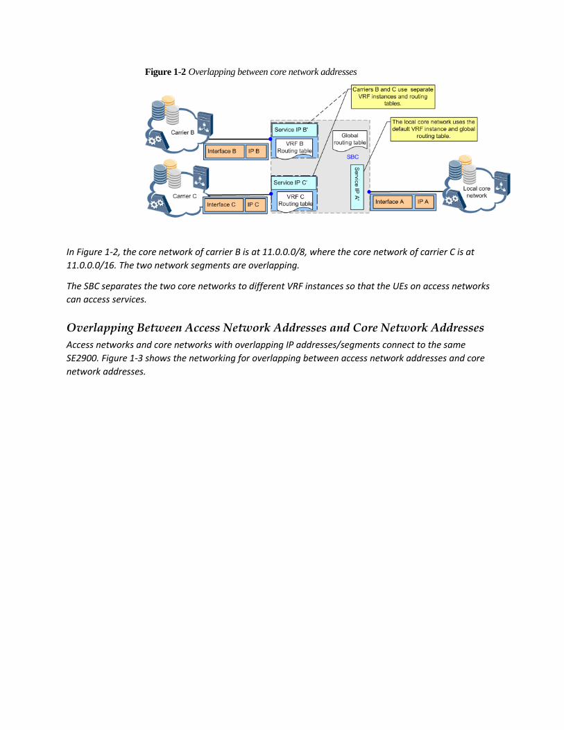
Figure 1-2 Overlapping between core network addresses
In Figure 1-2, the core network of carrier B is at 11.0.0.0/8, where the core network of carrier C is at
11.0.0.0/16. The two network segments are overlapping.
The SBC separates the two core networks to different VRF instances so that the UEs on access networks
can access services.
Overlapping Between Access Network Addresses and Core Network Addresses
Access networks and core networks with overlapping IP addresses/segments connect to the same
SE2900. Figure 1-3 shows the networking for overlapping between access network addresses and core
network addresses.
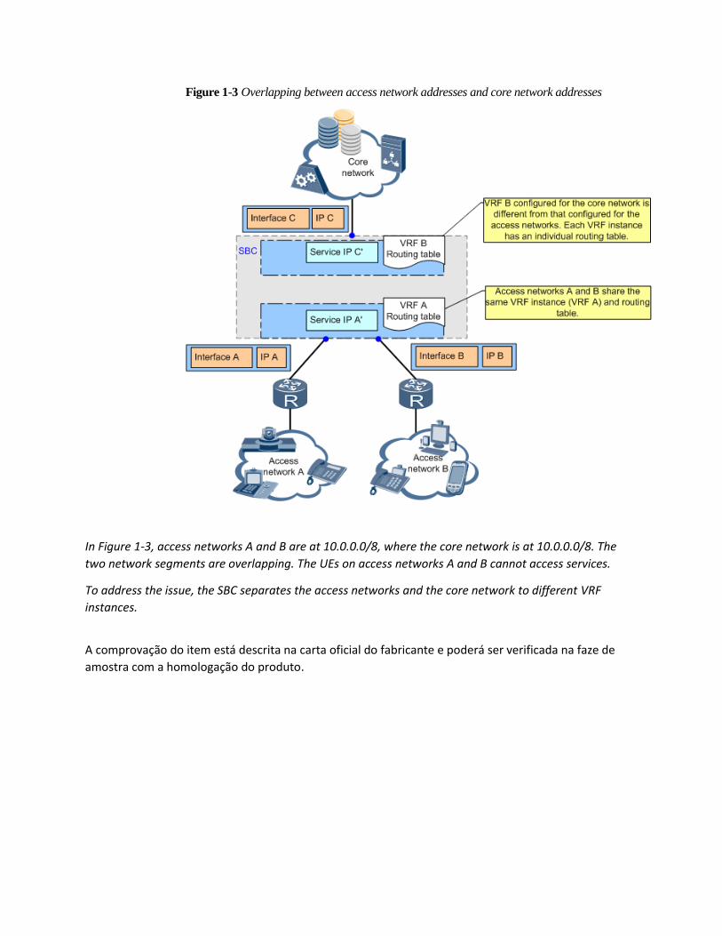
Figure 1-3 Overlapping between access network addresses and core network addresses
In Figure 1-3, access networks A and B are at 10.0.0.0/8, where the core network is at 10.0.0.0/8. The
two network segments are overlapping. The UEs on access networks A and B cannot access services.
To address the issue, the SBC separates the access networks and the core network to different VRF
instances.
A comprovação do item está descrita na carta oficial do fabricante e poderá ser verificada na faze de
amostra com a homologação do produto.
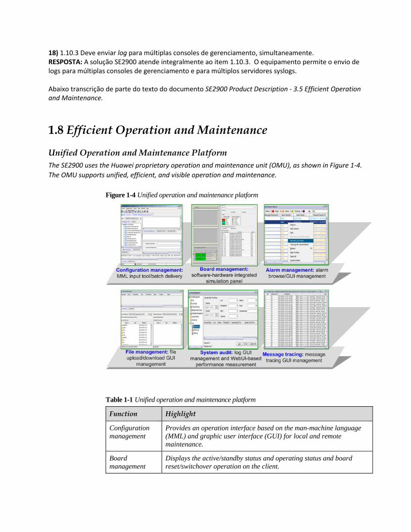
18) 1.10.3 Deve enviar log para múltiplas consoles de gerenciamento, simultaneamente. RESPOSTA: A solução SE2900 atende integralmente ao item 1.10.3. O equipamento permite o envio de logs para múltiplas consoles de gerenciamento e para múltiplos servidores syslogs. Abaixo transcrição de parte do texto do documento SE2900 Product Description - 3.5 Efficient Operation and Maintenance.
1.8 Efficient Operation and Maintenance
Unified Operation and Maintenance Platform
The SE2900 uses the Huawei proprietary operation and maintenance unit (OMU), as shown in Figure 1-4.
The OMU supports unified, efficient, and visible operation and maintenance.
Figure 1-4 Unified operation and maintenance platform
Table 1-1 Unified operation and maintenance platform
Function Highlight
Configuration
management
Provides an operation interface based on the man-machine language
(MML) and graphic user interface (GUI) for local and remote
maintenance.
Board
management
Displays the active/standby status and operating status and board
reset/switchover operation on the client.
Function Highlight
Alarm
management
Supports real-time alarm reporting when a fault occurs and marks
alarm severities using different colors in the alarm browse window. This function helps facilitate immediate fault identification and
rectification.
File
management
Supports easy and visualized file upload/download to boards on the
client.
System audit Supports log query, alarm query, and web user interface-based
(WebUI-based) performance measurement and fault diagnosis. This
function facilitates fault identification and rectification, and provides a reference for network maintenance and optimization.
Message tracing Supports the signaling tracing function. Signaling can be traced based
on the IP address, port number, or signaling link. Carriers can use the signaling tracing function to trace detailed signaling messages
exchanged in procedures, such as registration, call establishment and release, and subscription and notification, of a specific call. The
SE2900 supports end-to-end signaling tracing tasks and displays
signaling tracing results on the EMS, which improves the fault location efficiency.
GUI-based WebUI Interface
The SE2900 supports the GUI-based web user interface (WebUI), as shown in Figure 1-5. The WebUI
integrates performance management and patch and upgrade tools.
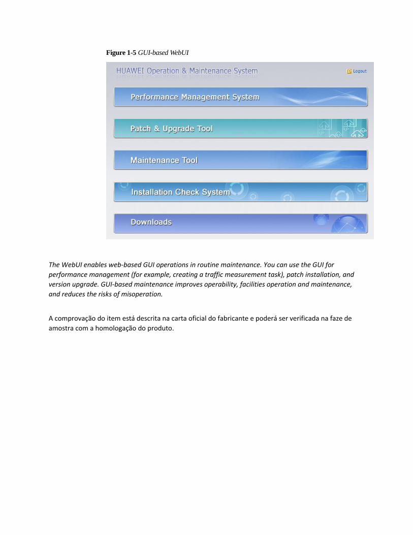
Figure 1-5 GUI-based WebUI
The WebUI enables web-based GUI operations in routine maintenance. You can use the GUI for
performance management (for example, creating a traffic measurement task), patch installation, and
version upgrade. GUI-based maintenance improves operability, facilities operation and maintenance,
and reduces the risks of misoperation.
A comprovação do item está descrita na carta oficial do fabricante e poderá ser verificada na faze de
amostra com a homologação do produto.
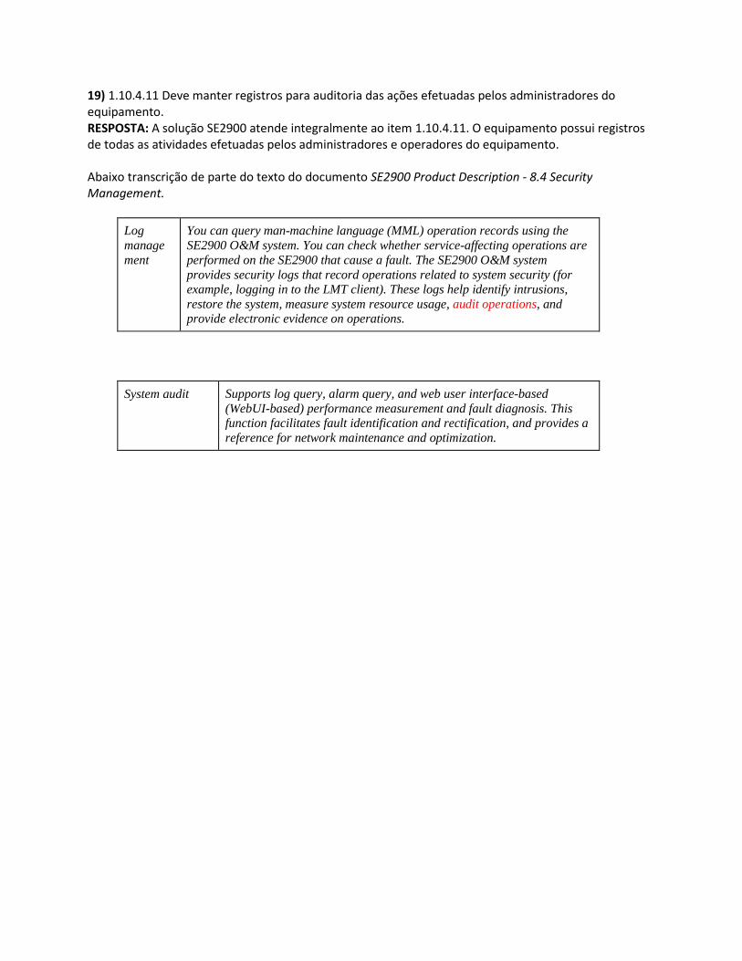
19) 1.10.4.11 Deve manter registros para auditoria das ações efetuadas pelos administradores do equipamento. RESPOSTA: A solução SE2900 atende integralmente ao item 1.10.4.11. O equipamento possui registros de todas as atividades efetuadas pelos administradores e operadores do equipamento. Abaixo transcrição de parte do texto do documento SE2900 Product Description - 8.4 Security Management.
Log
manage
ment
You can query man-machine language (MML) operation records using the
SE2900 O&M system. You can check whether service-affecting operations are
performed on the SE2900 that cause a fault. The SE2900 O&M system
provides security logs that record operations related to system security (for example, logging in to the LMT client). These logs help identify intrusions,
restore the system, measure system resource usage, audit operations, and provide electronic evidence on operations.
System audit Supports log query, alarm query, and web user interface-based
(WebUI-based) performance measurement and fault diagnosis. This function facilitates fault identification and rectification, and provides a
reference for network maintenance and optimization.


![27.11 - Palestra Zeneide - IFRN III [Modo de Compatibilidade] · TCU não diligencia ... O SISACNET é uma plataforma web, ... cgurn@cgu.gov.br francisco.gadelha@cgu.gov.br alice.correia@cgu.gov.br](https://static.fdocumentos.com/doc/165x107/5be6a44109d3f247448d5fb3/2711-palestra-zeneide-ifrn-iii-modo-de-compatibilidade-tcu-nao-diligencia.jpg)