SMM0330 PRINCÍPIOS DE ANÁLISE DE FALHAS 2... · • LÍQUIDO PENETRANTE, ... • Após o desastre...
53
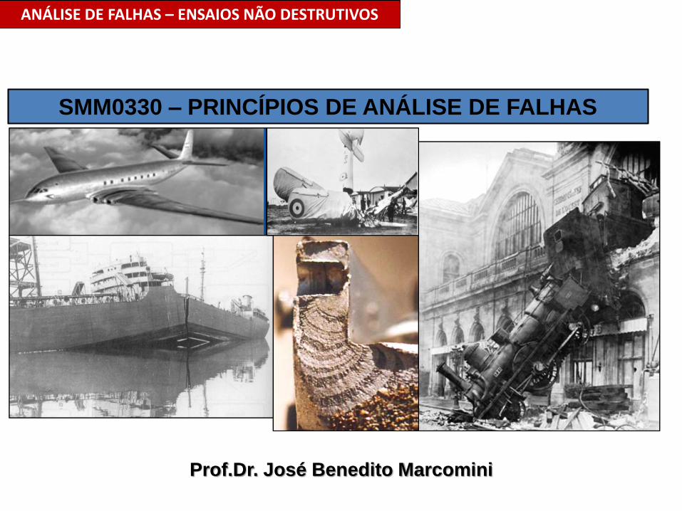
Prof.Dr. José Benedito Marcomini ANÁLISE DE FALHAS – ENSAIOS NÃO DESTRUTIVOS SMM0330 – PRINCÍPIOS DE ANÁLISE DE FALHAS
-
Upload
nguyenmien -
Category
Documents
-
view
217 -
download
0
Transcript of SMM0330 PRINCÍPIOS DE ANÁLISE DE FALHAS 2... · • LÍQUIDO PENETRANTE, ... • Após o desastre...
Prof.Dr. José Benedito Marcomini
ANÁLISE DE FALHAS – ENSAIOS NÃO DESTRUTIVOS
SMM0330 – PRINCÍPIOS DE ANÁLISE DE FALHAS
Prof.Dr. José Benedito Marcomini
ANÁLISE DE FALHAS – ENSAIOS NÃO DESTRUTIVOS
REFERÊNCIAS:
• APOSTILAS-ABENDE-RICARDO ANDREUCCI;
• MATERIAL DA GE INPECTION TECHNOLOGIES.
Prof.Dr. José Benedito Marcomini
ANÁLISE DE FALHAS – ENSAIOS NÃO DESTRUTIVOS
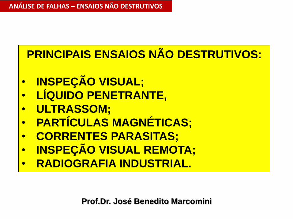
PRINCIPAIS ENSAIOS NÃO DESTRUTIVOS:
• INSPEÇÃO VISUAL;
• LÍQUIDO PENETRANTE,
• ULTRASSOM;
• PARTÍCULAS MAGNÉTICAS;
• CORRENTES PARASITAS;
• INSPEÇÃO VISUAL REMOTA;
• RADIOGRAFIA INDUSTRIAL.
Prof.Dr. José Benedito Marcomini
ANÁLISE DE FALHAS – ENSAIOS NÃO DESTRUTIVOS
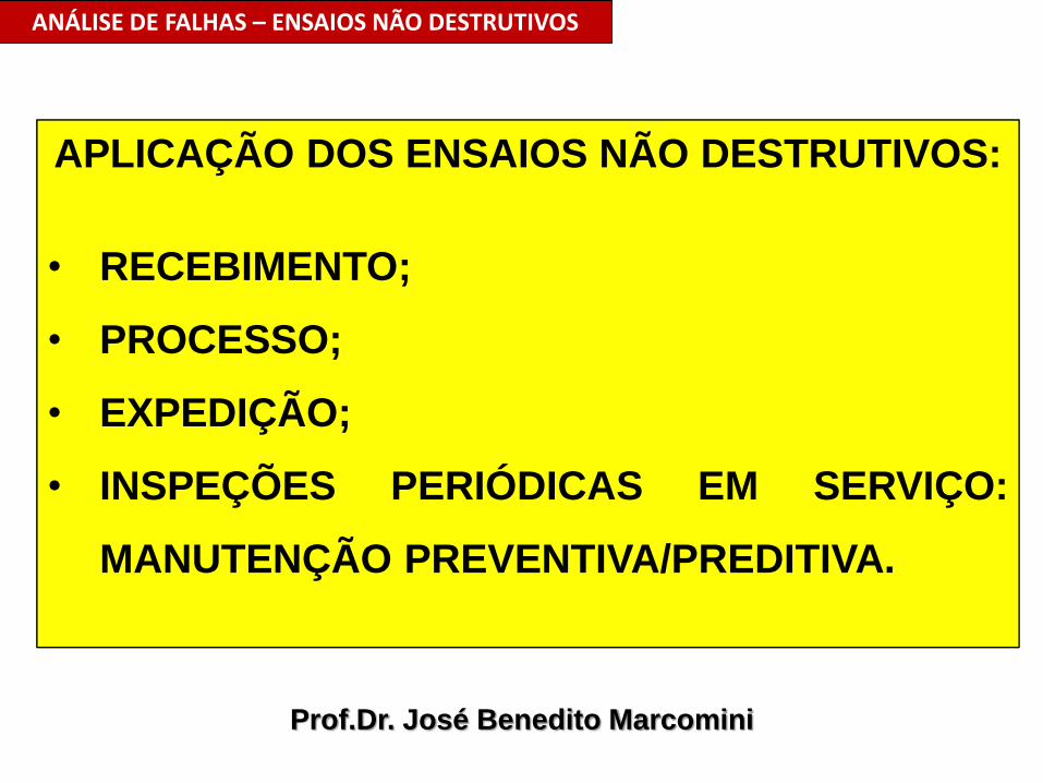
APLICAÇÃO DOS ENSAIOS NÃO DESTRUTIVOS:
• RECEBIMENTO;
• PROCESSO;
• EXPEDIÇÃO;
• INSPEÇÕES PERIÓDICAS EM SERVIÇO:
MANUTENÇÃO PREVENTIVA/PREDITIVA.
Prof.Dr. José Benedito Marcomini
ANÁLISE DE FALHAS – ENSAIOS NÃO DESTRUTIVOS
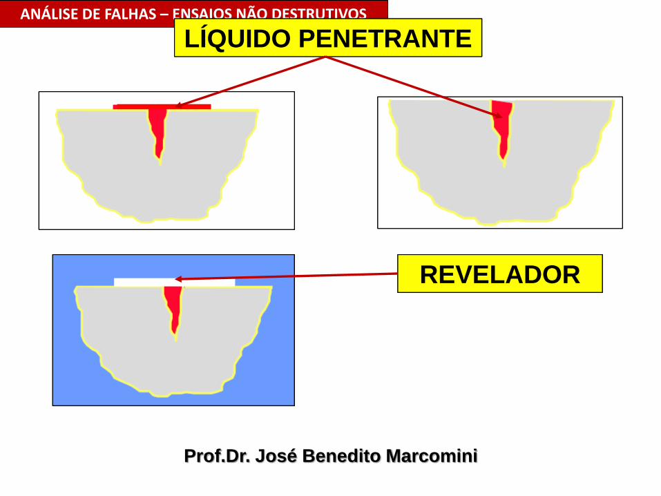
LÍQUIDO PENETRANTE
REVELADOR

Prof.Dr. José Benedito Marcomini
ANÁLISE DE FALHAS – ENSAIOS NÃO DESTRUTIVOS
www.inspbrasil.com.br
Prof.Dr. José Benedito Marcomini
ANÁLISE DE FALHAS – ENSAIOS NÃO DESTRUTIVOS
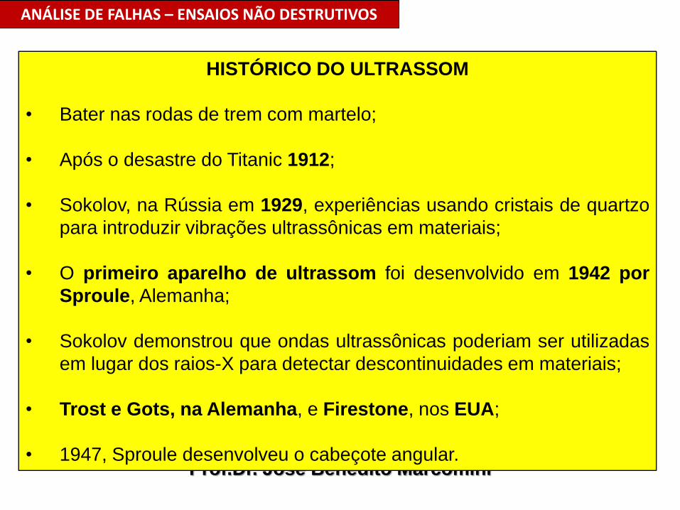
HISTÓRICO DO ULTRASSOM
• Bater nas rodas de trem com martelo;
• Após o desastre do Titanic 1912;
• Sokolov, na Rússia em 1929, experiências usando cristais de quartzo
para introduzir vibrações ultrassônicas em materiais;
• O primeiro aparelho de ultrassom foi desenvolvido em 1942 por
Sproule, Alemanha;
• Sokolov demonstrou que ondas ultrassônicas poderiam ser utilizadas
em lugar dos raios-X para detectar descontinuidades em materiais;
• Trost e Gots, na Alemanha, e Firestone, nos EUA;
• 1947, Sproule desenvolveu o cabeçote angular.

Prinziple: Analog technique
Amplifier
workpiece
probe
Horizontal
sweep
clock
Pulser
IP
BE
CRTReal time
signal display,
shot by shot
Prof.Dr. José Benedito Marcomini
ANÁLISE DE FALHAS – ENSAIOS NÃO DESTRUTIVOS
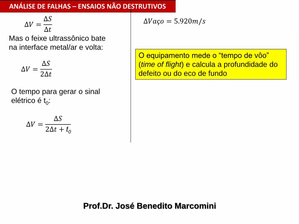
∆𝑉 =∆𝑆
∆𝑡Mas o feixe ultrassônico bate
na interface metal/ar e volta:
∆𝑉 =∆𝑆
2∆𝑡
∆𝑉 =∆𝑆
2∆𝑡 + t0
O tempo para gerar o sinal
elétrico é t0:
∆𝑉𝑎ç𝑜 = 5.920𝑚/𝑠
O equipamento mede o “tempo de vôo”
(time of flight) e calcula a profundidade do
defeito ou do eco de fundo
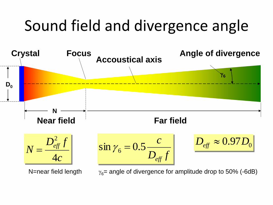
Sound field and divergence angle
c
fDN
eff
4
2
fD
c
eff
5.0sin 6
N
Near field Far field
Focus Angle of divergenceCrystalAccoustical axis
D0
6
097.0 DDeff
6= angle of divergence for amplitude drop to 50% (-6dB)N=near field length
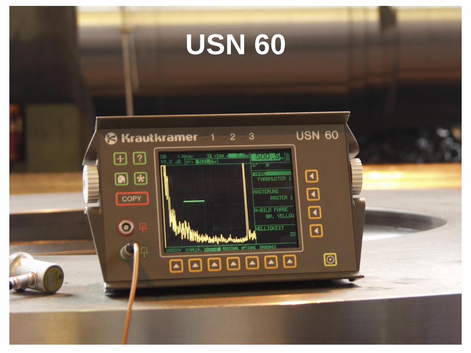
USN 60

d
d
Cabeçote
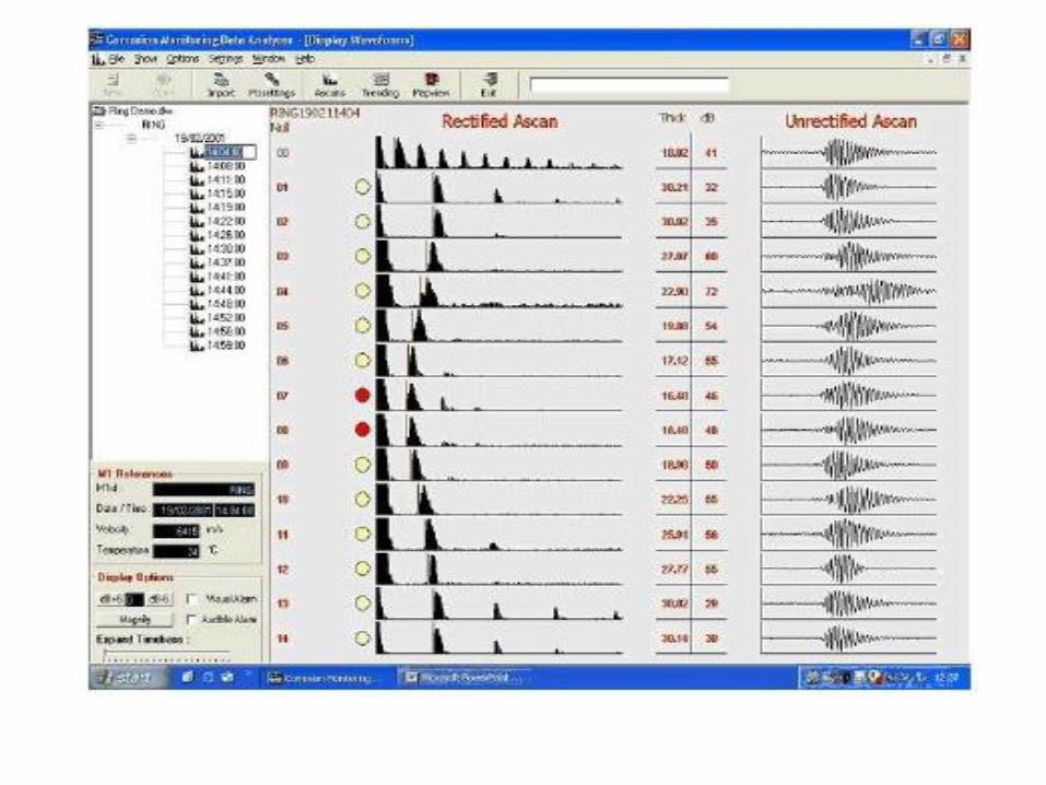
DETECÇÃO DA DESCONTINUIDADE – APRESENTAÇÃO A-SCAN
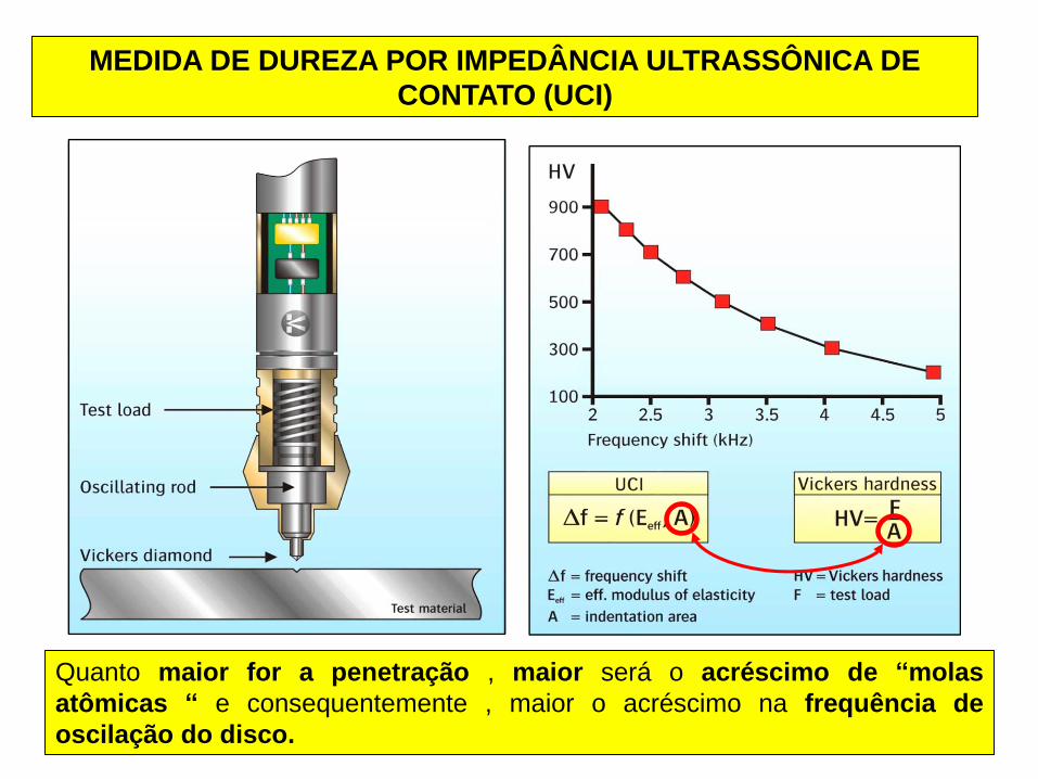
MEDIDA DE DUREZA POR IMPEDÂNCIA ULTRASSÔNICA DE
CONTATO (UCI)
Quanto maior for a penetração , maior será o acréscimo de “molas
atômicas “ e consequentemente , maior o acréscimo na frequência de
oscilação do disco.
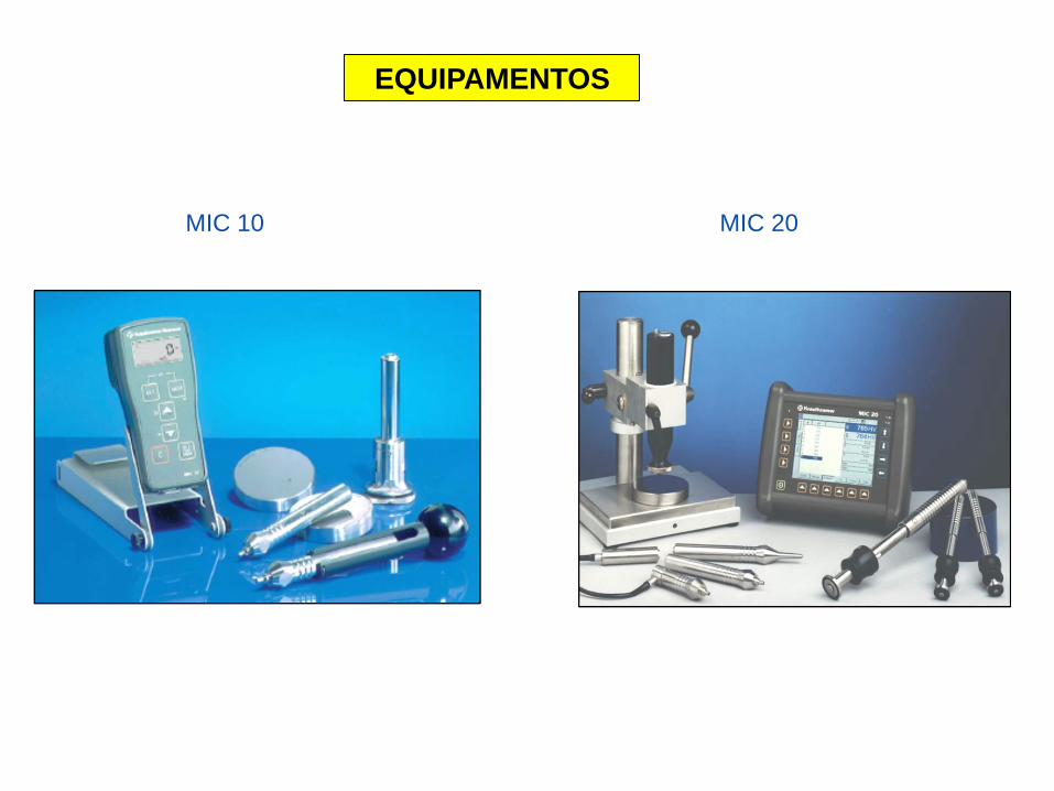
MIC 10 MIC 20
EQUIPAMENTOS
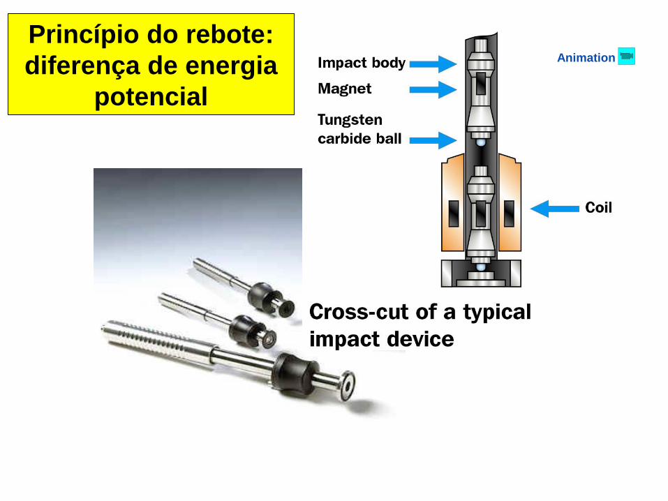
Princípio do rebote:
diferença de energia
potencial
Animation
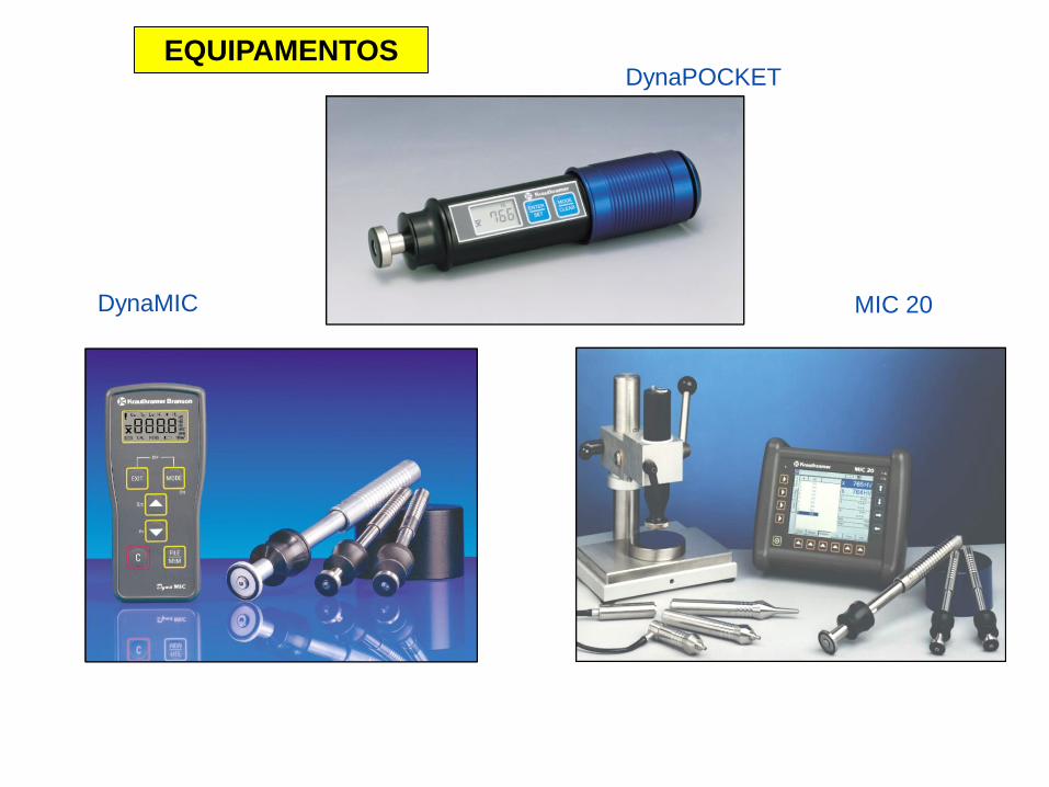
DynaMIC MIC 20
DynaPOCKETEQUIPAMENTOS
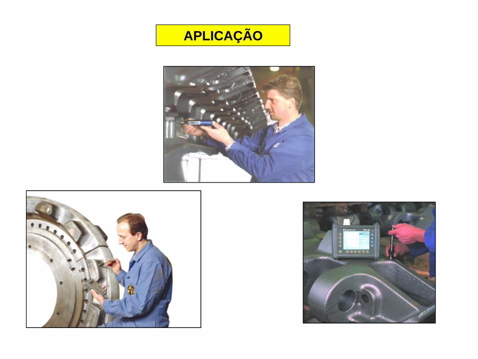
APLICAÇÃO
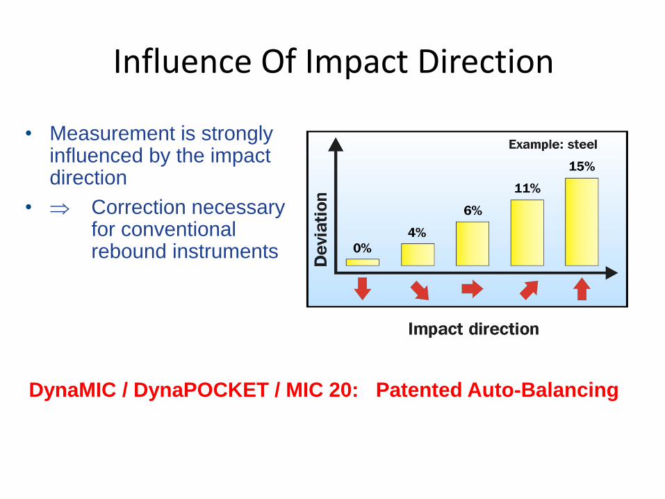
DynaMIC / DynaPOCKET / MIC 20: Patented Auto-Balancing
Influence Of Impact Direction
• Measurement is strongly influenced by the impact direction
• Correction necessaryfor conventionalrebound instruments
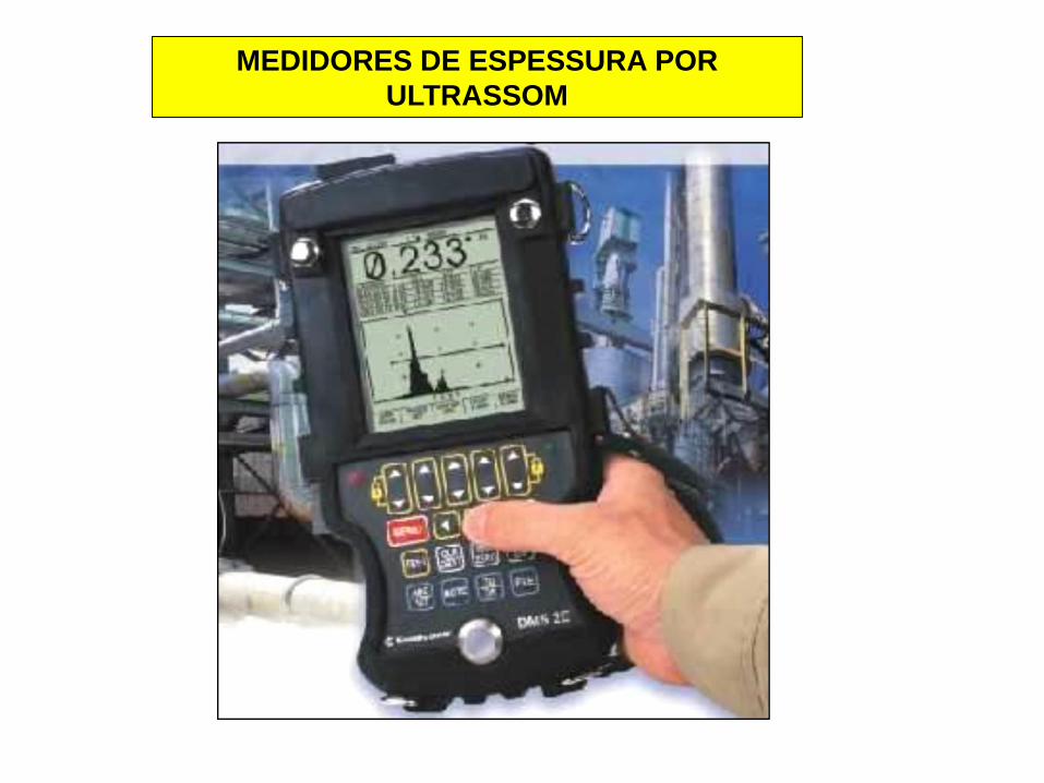
MEDIDORES DE ESPESSURA POR
ULTRASSOM
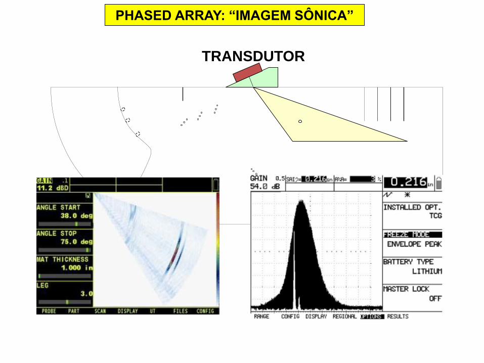
TRANSDUTOR
PHASED ARRAY: “IMAGEM SÔNICA”
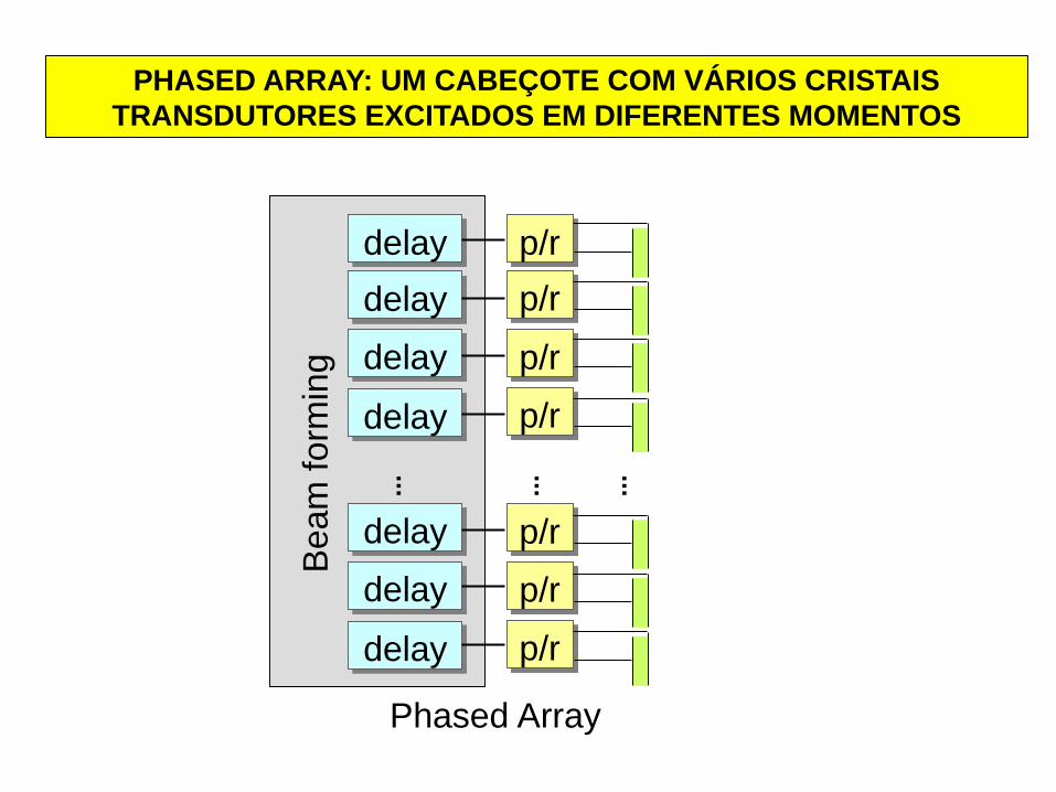
Phased Array
p/r
p/r
p/r
p/r
p/r
p/r
p/r
delay
delay
delay
delay
delay
delay
delay
Beam
form
ing
...
...
...
PHASED ARRAY: UM CABEÇOTE COM VÁRIOS CRISTAIS
TRANSDUTORES EXCITADOS EM DIFERENTES MOMENTOS
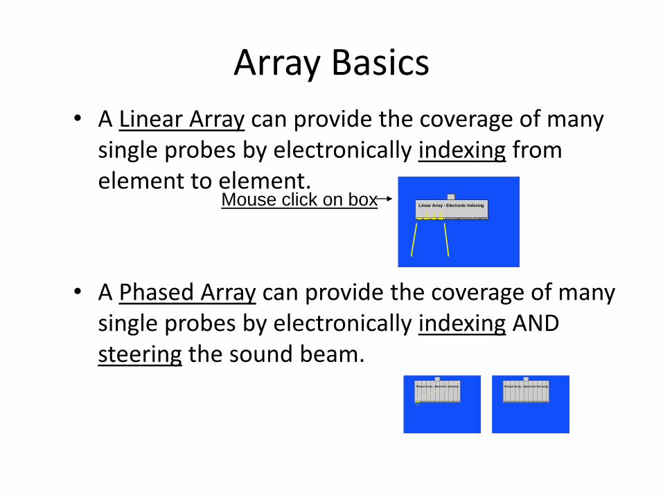
Array Basics
• A Linear Array can provide the coverage of many single probes by electronically indexing from element to element.
• A Phased Array can provide the coverage of many single probes by electronically indexing AND steering the sound beam.
Linear Array - Electronic Indexing
Phased Array - Electronic Steering Phased Array - Electronic Focusing
Mouse click on box
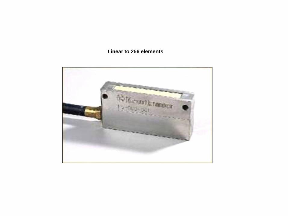
Linear to 256 elements
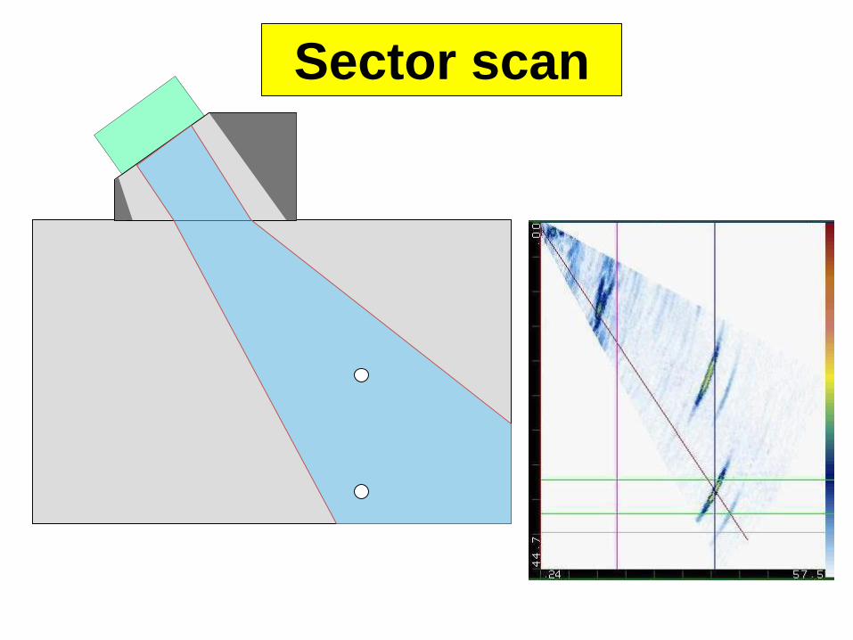
Sector scan
Prof.Dr. José Benedito Marcomini
ANÁLISE DE FALHAS – ENSAIOS NÃO DESTRUTIVOS
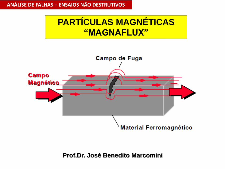
PARTÍCULAS MAGNÉTICAS
“MAGNAFLUX”
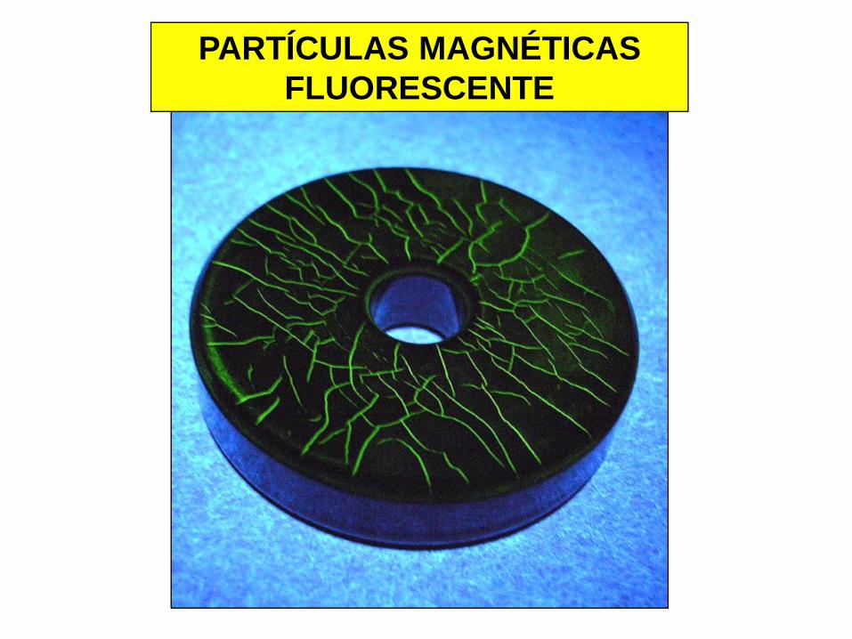
PARTÍCULAS MAGNÉTICAS
FLUORESCENTE
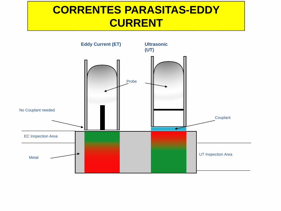
Ultrasonic
(UT)
Eddy Current (ET)
Couplant
EC Inspection Area
UT Inspection Area
No Couplant needed
Metal
Probe
CORRENTES PARASITAS-EDDY
CURRENT
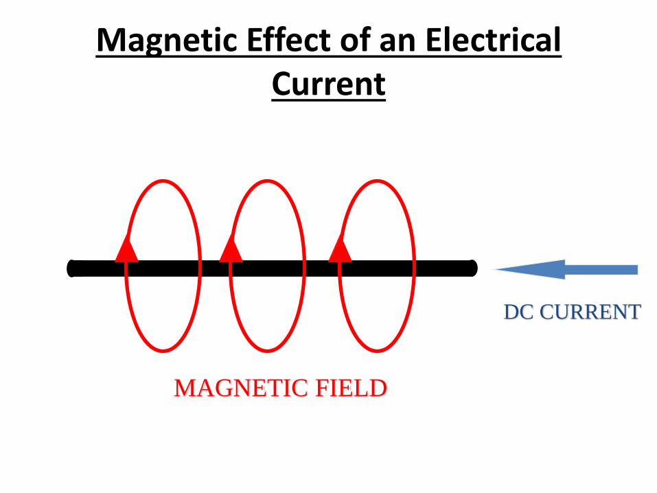
Magnetic Effect of an Electrical Current
DC CURRENT
MAGNETIC FIELD
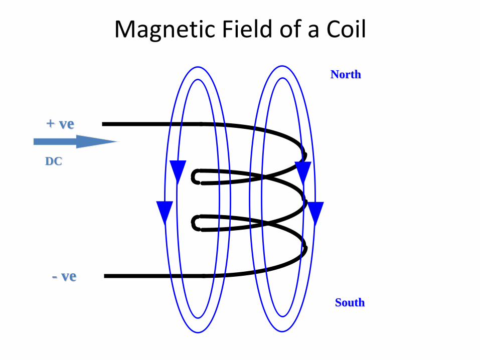
Magnetic Field of a Coil
+ ve
- ve
DC
North
South
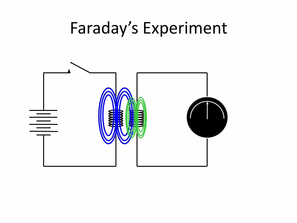
Faraday’s Experiment
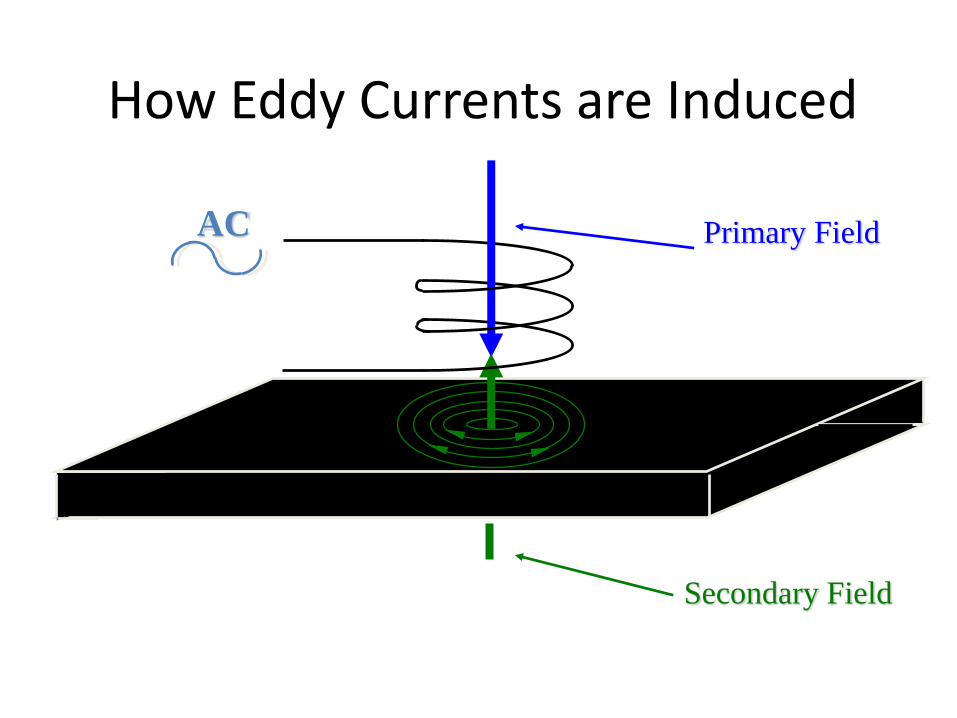
AC Primary Field
Secondary Field
How Eddy Currents are Induced

Eddy Current Flaw Detection :-
Primary Field
Secondary Field
AC Fault
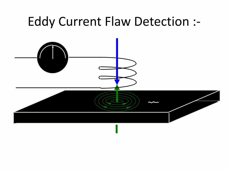
Eddy Current Flaw Detection :-
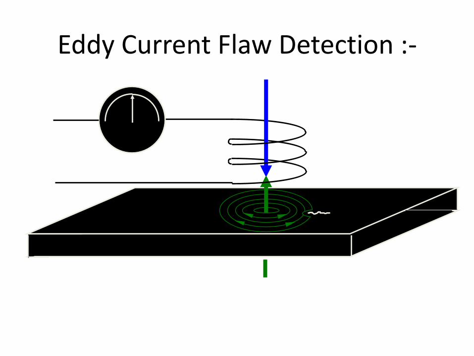
Eddy Current Flaw Detection :-

Eddy Current Flaw Detection :-
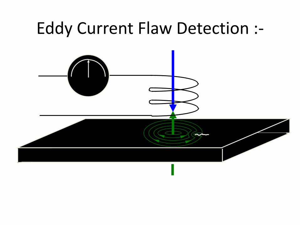
Eddy Current Flaw Detection :-

Eddy Current Flaw Detection :-
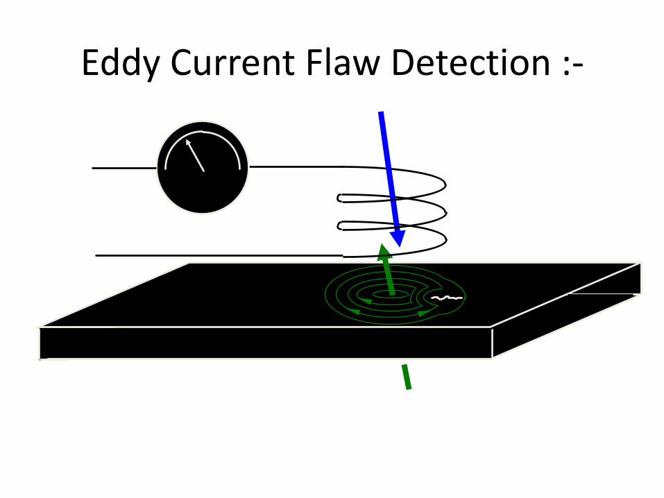
Eddy Current Flaw Detection :-

Eddy Current Flaw Detection :-
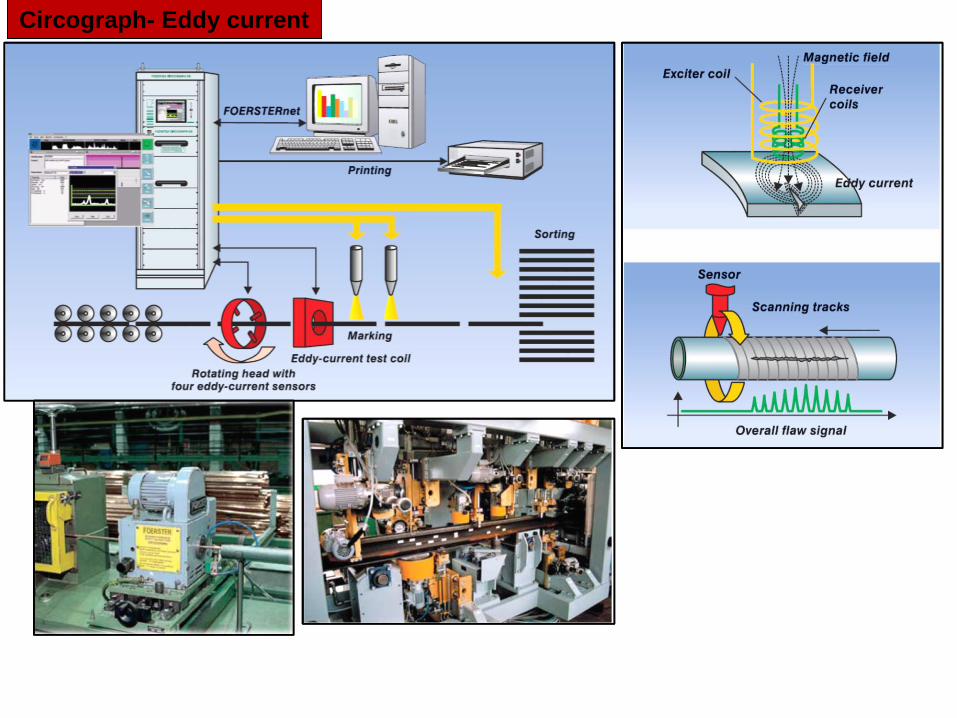
Circograph- Eddy current
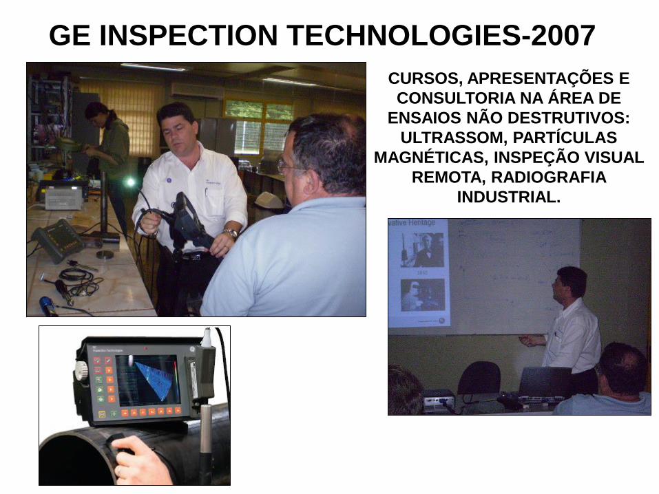
GE INSPECTION TECHNOLOGIES-2007
CURSOS, APRESENTAÇÕES E
CONSULTORIA NA ÁREA DE
ENSAIOS NÃO DESTRUTIVOS:
ULTRASSOM, PARTÍCULAS
MAGNÉTICAS, INSPEÇÃO VISUAL
REMOTA, RADIOGRAFIA
INDUSTRIAL.
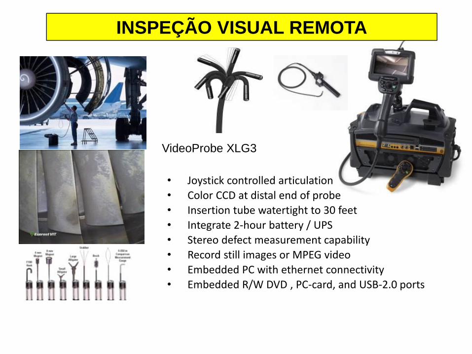
• Joystick controlled articulation
• Color CCD at distal end of probe
• Insertion tube watertight to 30 feet
• Integrate 2-hour battery / UPS
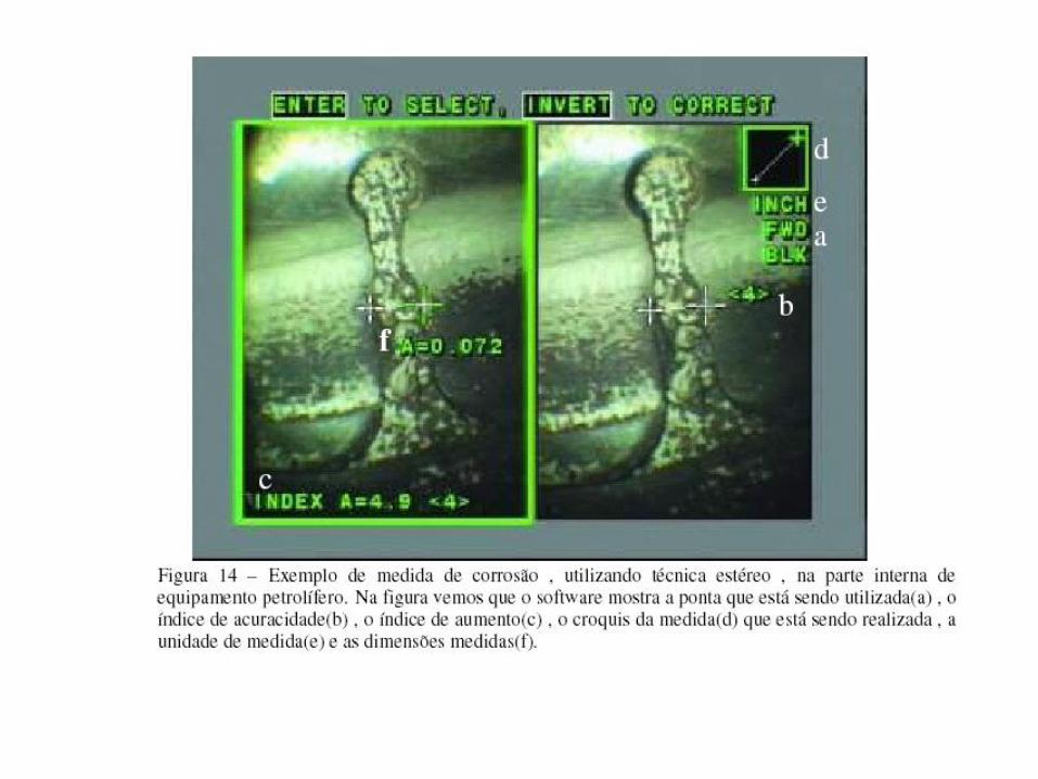
• Stereo defect measurement capability
• Record still images or MPEG video
• Embedded PC with ethernet connectivity
• Embedded R/W DVD , PC-card, and USB-2.0 ports
VideoProbe XLG3
INSPEÇÃO VISUAL REMOTA

PC Operating System
• Running Standard Applications
• Browser
• Network Software
• Internet Protocol
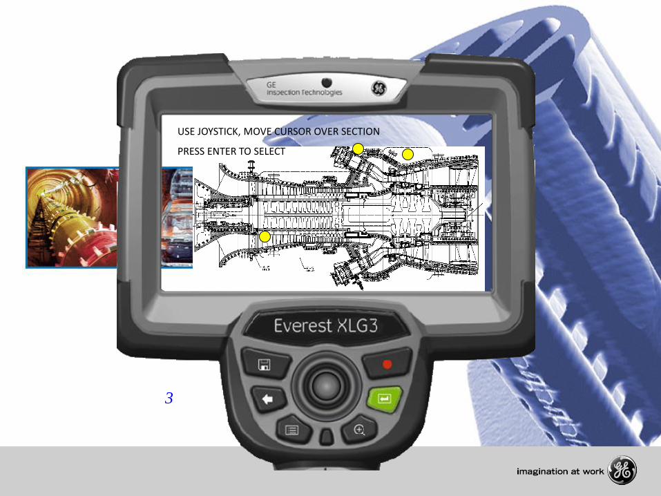
3
USE JOYSTICK, MOVE CURSOR OVER SECTION
PRESS ENTER TO SELECT
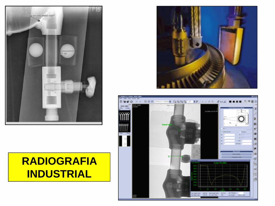
RADIOGRAFIA
INDUSTRIAL
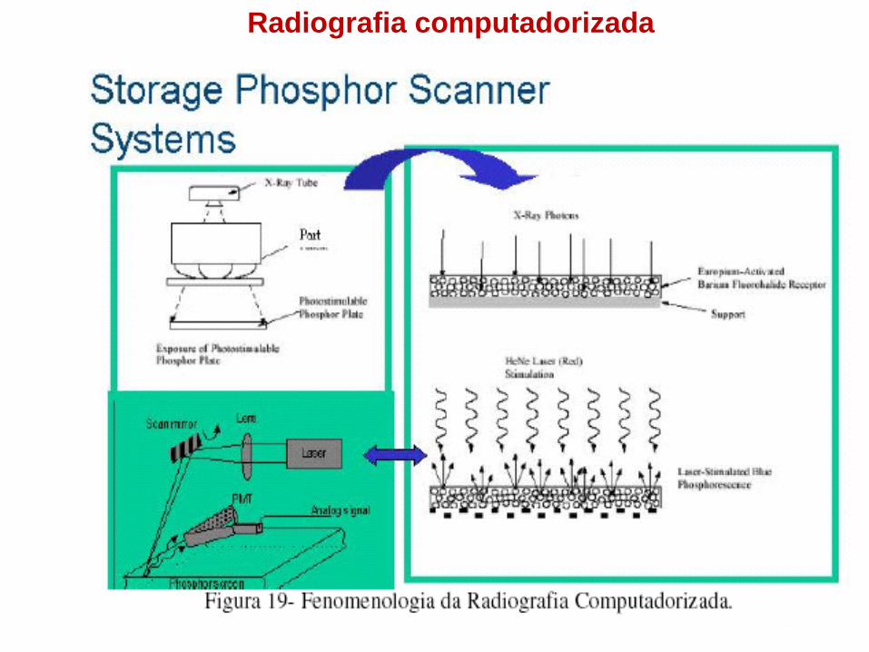
Radiografia computadorizada
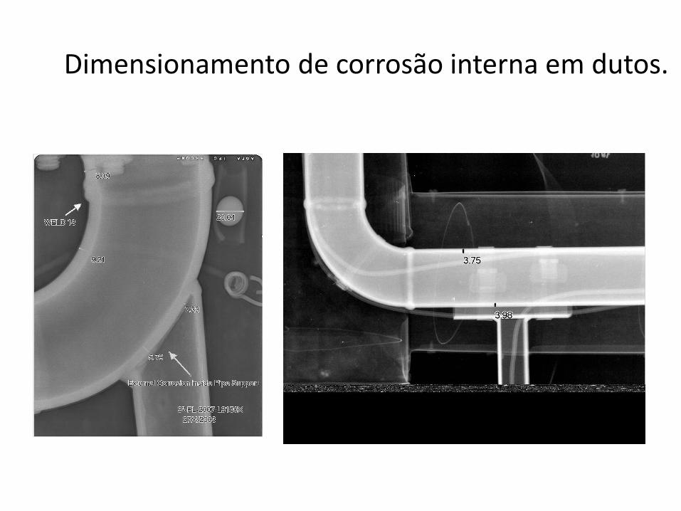
Dimensionamento de corrosão interna em dutos.
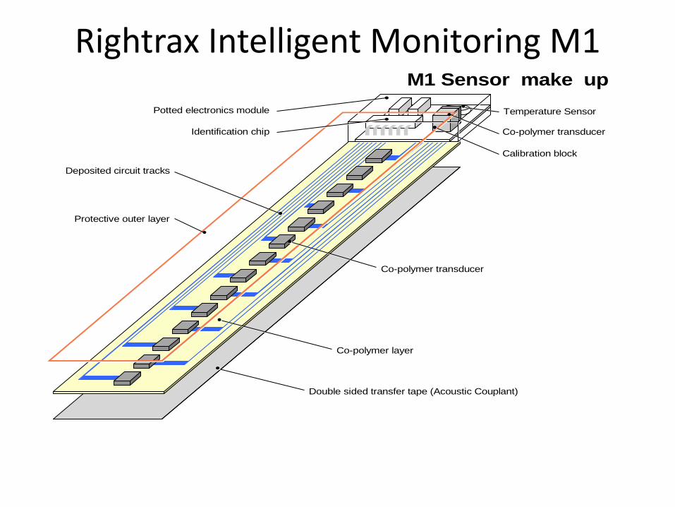
Rightrax Intelligent Monitoring M1 SENSOR
Double sided transfer tape (Acoustic Couplant)
Co-polymer layer
Co-polymer transducer
Protective outer layer
Deposited circuit tracks
Potted electronics module
Calibration block
Identification chip Co-polymer transducer
Temperature Sensor
M1 Sensor make up
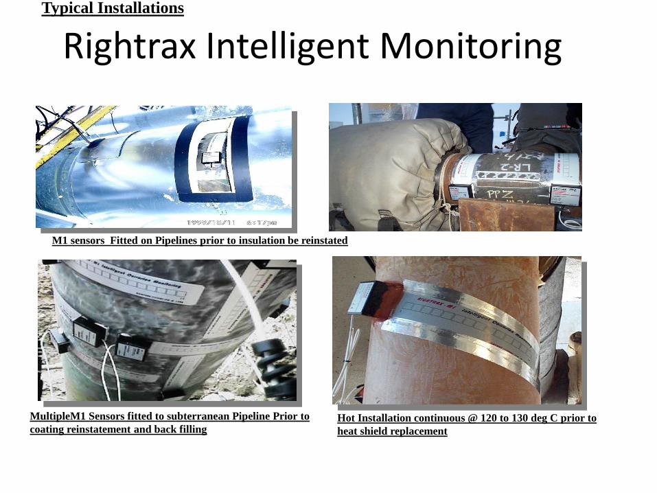
Rightrax Intelligent MonitoringTypical Installations
M1 sensors Fitted on Pipelines prior to insulation be reinstated
MultipleM1 Sensors fitted to subterranean Pipeline Prior to
coating reinstatement and back fillingHot Installation continuous @ 120 to 130 deg C prior to
heat shield replacement
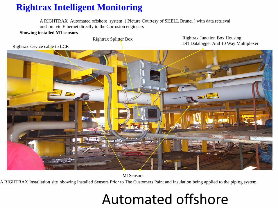
A RIGHTRAX Installation site showing Installed Sensors Prior to The Customers Paint and Insulation being applied to the piping system
M1Sensors
Rightrax Junction Box Housing
Dl1 Datalogger And 10 Way Multiplexer
A RIGHTRAX Automated offshore system ( Picture Courtesy of SHELL Brunei ) with data retrieval
onshore vie Ethernet directly to the Corrosion engineers
Rightrax Splitter Box
Rightrax service cable to LCR
Showing installed M1 sensors
Rightrax Intelligent Monitoring
Automated offshore

Prof.Dr. José Benedito Marcomini
ANÁLISE DE FALHAS – ENSAIOS NÃO DESTRUTIVOS
FIM