The 1.5 meter solar telescope GREGORFirst ideas to build a telescope of the 1.5 meter class, to...
14
Astron. Nachr. / AN 333, No. 9, 796 – 809 (2012) / DOI 10.1002/asna.201211725 The 1.5 meter solar telescope GREGOR W. Schmidt 1, , O. von der L¨ uhe 1 , R. Volkmer 1 , C. Denker 3 , S.K. Solanki 4 , H. Balthasar 3 , N. Bello Gonzalez 1 , Th. Berkefeld 1 , M. Collados 5 , A. Fischer 1 , C. Halbgewachs 1 , F. Heidecke 1 , A. Hofmann 3 , F. Kneer 2 , A. Lagg 4 , H. Nicklas 2 , E. Popow 3 , K.G. Puschmann 3 , D. Schmidt 1 , M. Sigwarth 1 , M. Sobotka 6 , D. Soltau 1 , J. Staude 3 , K.G. Strassmeier 3 , and T.A. Waldmann 1 1 Kiepenheuer-Institut f¨ ur Sonnenphysik, Sch¨ oneckstraße 6, 79104 Freiburg, Germany 2 Institut f¨ ur Astrophysik der Georg-August-Universit¨ at G¨ ottingen, Friedrich-Hund-Platz 1, 37077 G¨ ottingen, Germany 3 Leibniz-Institut f¨ ur Astrophysik, An der Sternwarte 16, 14482 Potsdam, Germany 4 Max-Planck-Institut f¨ ur Sonnensystemforschung, Max-Planck-Straße 2, 37191 Katlenburg-Lindau, Germany 5 Instituto de Astrof´ ısica de Canarias, V´ ıa L´ actea, 38200 La Laguna (Tenerife), Spain 6 Astronomical Institute AS CR, Friˇ cova 298, 25165 Ondˇ rejov, Czech Republic Received 2012 Aug 30, accepted 2012 Sep 23 Published online 2012 Nov 2 Key words instrumentation: high angular resolution – Sun: magnetic fields – telescopes The 1.5 m telescope GREGOR opens a new window to the understanding of solar small-scale magnetism. The first light instrumentation includes the Gregor Fabry P´ erot Interferometer (GFPI), a filter spectro-polarimeter for the visible wave- length range, the GRating Infrared Spectro-polarimeter (GRIS) and the Broad-Band Imager (BBI). The excellent perfor- mance of the first two instruments has already been demonstrated at the Vacuum Tower Telescope. GREGOR is Europe’s largest solar telescope and number 3 in the world. Its all-reflective Gregory design provides a large wavelength cover- age from the near UV up to at least 5 microns. The field of view has a diameter of 150 . GREGOR is equipped with a high-order adaptive optics system, with a subaperture size of 10 cm, and a deformable mirror with 256 actuators. The science goals are focused on, but not limited to, solar magnetism. GREGOR allows us to measure the emergence and disappearance of magnetic flux at the solar surface at spatial scales well below 100 km. Thanks to its spectro-polarimetric capabilities, GREGOR will measure the interaction between the plasma flows, different kinds of waves, and the magnetic field. This will foster our understanding of the processes that heat the chromosphere and the outer layers of the solar atmosphere. Observations of the surface magnetic field at very small spatial scales will shed light on the variability of the solar brightness. c 2012 WILEY-VCH Verlag GmbH& Co. KGaA, Weinheim 1 Introduction The installation of the 1.5 m solar telescope GREGOR at the Observatorio del Teide (OT) is a major milestone for solar physics in Europe. Not only is GREGOR Europe’s largest and most powerful solar telescope, it also forms, together with the neighboring 70cm Vacuum Tower Tele- scope (VTT) and the 90cm THEMIS, the world’s most powerful set of solar telescopes at a single site. Figure 1 shows an aerial view of the OT with the three large so- lar telescopes aligned along the ridge, with THEMIS in the lower right corner of the image, followed by the VTT and GREGOR. First ideas to build a telescope of the 1.5 meter class, to replace the 45 cm Gregory-Coud´ e telescope were presented in 1997. The abstract of a GREGOR flyer, prepared in late 1999 reads: GREGOR is a large solar telescope with an aperture of 1.5 m. It is equipped with adaptive optics and a polarimetry system. It is designed for high-precision measurements of the magnetic field and the gas motion in the solar photosphere and chromosphere Corresponding author: [email protected] with a resolution of 70 km on the Sun, equivalent to the photon mean-free path in the photosphere. GREGOR will be installed at the Observatorio del Teide, Tenerife. The focal plane instrumenta- tion includes a high resolution filter spectrometer and a polarimet- ric spectrograph for the visible and the near-UV spectral range. The official proposal was prepared in March 2000. From the beginning, it was clear that the new telescope would not continue the route of evacuated telescopes, but would be an open one (von der L¨ uhe et al. 2000). This change of paradigm had important consequences, and led to the de- cision to have a removable dome to allow for air flushing. Mirror seeing on the primary was a major concern, there- fore a mirror from a novel material, silicon carbide, was en- visioned, in order to facilitate cooling from the backside. The open dome concept was realized, but unfortunately, the silicon carbide solution failed, for technical reasons. The finally installed primary mirror is now made of light- weighted Zerodur, also with backside cooling. A retrospec- tive of the GREGOR project and an overview of the cor- responding literature can be found in Kneer (2012) and in Denker et al. (2012). c 2012 WILEY-VCH Verlag GmbH& Co. KGaA, Weinheim
Transcript of The 1.5 meter solar telescope GREGORFirst ideas to build a telescope of the 1.5 meter class, to...
Astron. Nachr. / AN 333, No. 9, 796 – 809 (2012) / DOI 10.1002/asna.201211725
The 1.5 meter solar telescope GREGOR
W. Schmidt1,�, O. von der Luhe1, R. Volkmer1, C. Denker3, S.K. Solanki4, H. Balthasar3, N. BelloGonzalez1, Th. Berkefeld1, M. Collados5, A. Fischer1, C. Halbgewachs1, F. Heidecke1, A. Hofmann3,F. Kneer2, A. Lagg4, H. Nicklas2, E. Popow3, K.G. Puschmann3, D. Schmidt1, M. Sigwarth1,M. Sobotka6, D. Soltau1, J. Staude3, K.G. Strassmeier3, and T.A. Waldmann1
1 Kiepenheuer-Institut fur Sonnenphysik, Schoneckstraße 6, 79104 Freiburg, Germany2 Institut fur Astrophysik der Georg-August-Universitat Gottingen, Friedrich-Hund-Platz 1, 37077 Gottingen, Germany3 Leibniz-Institut fur Astrophysik, An der Sternwarte 16, 14482 Potsdam, Germany4 Max-Planck-Institut fur Sonnensystemforschung, Max-Planck-Straße 2, 37191 Katlenburg-Lindau, Germany5 Instituto de Astrofısica de Canarias, Vıa Lactea, 38200 La Laguna (Tenerife), Spain6 Astronomical Institute AS CR, Fricova 298, 25165 Ondrejov, Czech Republic
Received 2012 Aug 30, accepted 2012 Sep 23Published online 2012 Nov 2
Key words instrumentation: high angular resolution – Sun: magnetic fields – telescopes
The 1.5 m telescope GREGOR opens a new window to the understanding of solar small-scale magnetism. The first lightinstrumentation includes the Gregor Fabry Perot Interferometer (GFPI), a filter spectro-polarimeter for the visible wave-length range, the GRating Infrared Spectro-polarimeter (GRIS) and the Broad-Band Imager (BBI). The excellent perfor-mance of the first two instruments has already been demonstrated at the Vacuum Tower Telescope. GREGOR is Europe’slargest solar telescope and number 3 in the world. Its all-reflective Gregory design provides a large wavelength cover-age from the near UV up to at least 5 microns. The field of view has a diameter of 150′′ . GREGOR is equipped witha high-order adaptive optics system, with a subaperture size of 10 cm, and a deformable mirror with 256 actuators. Thescience goals are focused on, but not limited to, solar magnetism. GREGOR allows us to measure the emergence anddisappearance of magnetic flux at the solar surface at spatial scales well below 100 km. Thanks to its spectro-polarimetriccapabilities, GREGOR will measure the interaction between the plasma flows, different kinds of waves, and the magneticfield. This will foster our understanding of the processes that heat the chromosphere and the outer layers of the solaratmosphere. Observations of the surface magnetic field at very small spatial scales will shed light on the variability of thesolar brightness.
c© 2012 WILEY-VCH Verlag GmbH & Co. KGaA, Weinheim
1 Introduction
The installation of the 1.5 m solar telescope GREGOR atthe Observatorio del Teide (OT) is a major milestone forsolar physics in Europe. Not only is GREGOR Europe’slargest and most powerful solar telescope, it also forms,together with the neighboring 70 cm Vacuum Tower Tele-scope (VTT) and the 90 cm THEMIS, the world’s mostpowerful set of solar telescopes at a single site. Figure 1shows an aerial view of the OT with the three large so-lar telescopes aligned along the ridge, with THEMIS in thelower right corner of the image, followed by the VTT andGREGOR.
First ideas to build a telescope of the 1.5 meter class, toreplace the 45 cm Gregory-Coude telescope were presentedin 1997. The abstract of a GREGOR flyer, prepared in late1999 reads:
GREGOR is a large solar telescope with an aperture of 1.5 m.It is equipped with adaptive optics and a polarimetry system. Itis designed for high-precision measurements of the magnetic fieldand the gas motion in the solar photosphere and chromosphere
� Corresponding author: [email protected]
with a resolution of 70 km on the Sun, equivalent to the photonmean-free path in the photosphere. GREGOR will be installed atthe Observatorio del Teide, Tenerife. The focal plane instrumenta-tion includes a high resolution filter spectrometer and a polarimet-ric spectrograph for the visible and the near-UV spectral range.
The official proposal was prepared in March 2000. Fromthe beginning, it was clear that the new telescope wouldnot continue the route of evacuated telescopes, but wouldbe an open one (von der Luhe et al. 2000). This change ofparadigm had important consequences, and led to the de-cision to have a removable dome to allow for air flushing.Mirror seeing on the primary was a major concern, there-fore a mirror from a novel material, silicon carbide, was en-visioned, in order to facilitate cooling from the backside.The open dome concept was realized, but unfortunately,the silicon carbide solution failed, for technical reasons.The finally installed primary mirror is now made of light-weighted Zerodur, also with backside cooling. A retrospec-tive of the GREGOR project and an overview of the cor-responding literature can be found in Kneer (2012) and inDenker et al. (2012).
c© 2012 WILEY-VCH Verlag GmbH & Co. KGaA, Weinheim

Astron. Nachr. / AN (2012) 797
Fig. 1 (online colour at: www.an-journal.org) Aerial view of the Observatorio del Teide in Izana, Tenerife, with the solar telescopes(from bottom right diagonally along the ridge) THEMIS, VTT, and GREGOR. The fourth large building at some distance of GREOR isthe Optical Ground Station (OGS) of ESA. Small synoptic solar telescopes are installed adjacent to the OGS. The STELLA installationis located just opposite of the access road to the VTT. The Residencia of the IAC is seen in the left part of the image.
After about 10 years of planning, construction, and in-stallation, the final pieces of GREGOR and its first-lightinstruments were installed in 2011, and the science verifi-cation started in spring of 2012. Delays with the telescopeoptics allowed installing and test parts of the focal-plane in-struments, as well as the adaptive optics already in 2010.For these tests, a 1-meter mirror1 with the same focal lengthas the original primary mirror, was installed. As a result,the telescope was ready for science verification only a fewmonths after the installation of the primary mirror.
In the following sections, we present an overview of theGREGOR solar telescope and its focal-plane instruments.Section 2 summarizes the science goals of GREGOR. InSect. 3 the most important aspects of building, dome andtelescope structure are briefly described, and references forfurther reading are given. The first-light instruments andtheir capabilities are described in Sect. 4. The final sectionprovides an outlook to second-generation instruments.
2 Science with GREGOR
Magnetic fields control many processes on the Sun and itsvariability. Knowledge about the generation of the solar
1 This 1 m mirror, made of CESIC, was a prototype mirror for space ap-plications, and was made available to the GREGOR project by the Lock-heed Martin Solar and Astrophysics Lab (Palo Alto, USA).
magnetic field, its dynamical behavior and its disappearancefrom the solar surface is therefore indispensable for our un-derstanding of the Sun. In the photosphere, magnetic fieldsare visible at a variety of spatial scales and a range of lifetimes. The most prominent objects, the sunspots, have beenobserved ever since the invention of the telescope, and theseobservations led to the discovery of the solar cycle, wellbefore the magnetic origin of that cycle became known. In1908, sunspots were the first extraterrestrial objects wherestrong magnetic field could be measured. Nowadays, mea-surements of the cyclical behavior of the number, polarity,and location of sunspots provide an important test bed forsolar and stellar dynamos. To date, no convincing or con-clusive theory for the solar activity cycle exists. Besides the22-year magnetic cycle, longer cycles of solar activity mayexist, but none of these long-term changes can be predictedwith any certainty. The situation is not much different to-ward shorter time scales. The life cycle of sunspots spansa range from several hours up to three months, whereas theformation process itself takes only a few hours. Thanks tospace-borne observatories and the much improved spatialresolution of ground-based facilities, high-quality observa-tional data do now exist, but still not enough to allow for aconvincing theoretical or numerical model of sunspot for-mation.
www.an-journal.org c© 2012 WILEY-VCH Verlag GmbH & Co. KGaA, Weinheim
798 W. Schmidt et al.: GREGOR
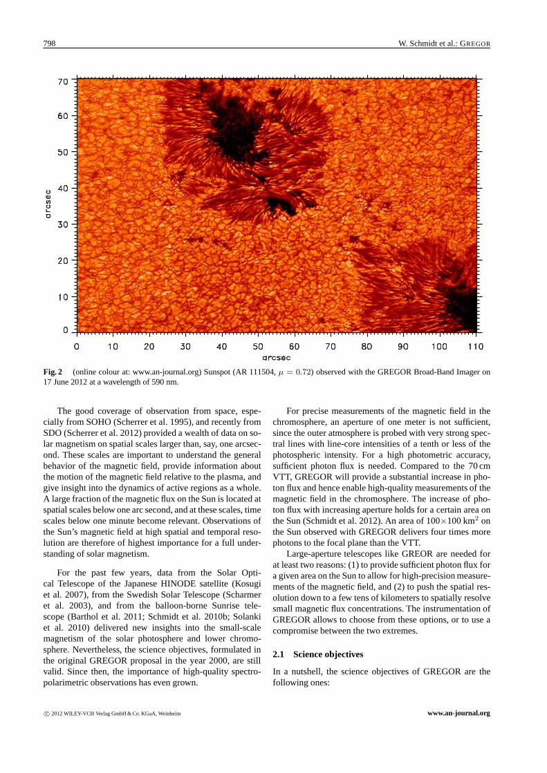
Fig. 2 (online colour at: www.an-journal.org) Sunspot (AR 111504, μ = 0.72) observed with the GREGOR Broad-Band Imager on17 June 2012 at a wavelength of 590 nm.
The good coverage of observation from space, espe-cially from SOHO (Scherrer et al. 1995), and recently fromSDO (Scherrer et al. 2012) provided a wealth of data on so-lar magnetism on spatial scales larger than, say, one arcsec-ond. These scales are important to understand the generalbehavior of the magnetic field, provide information aboutthe motion of the magnetic field relative to the plasma, andgive insight into the dynamics of active regions as a whole.A large fraction of the magnetic flux on the Sun is located atspatial scales below one arc second, and at these scales, timescales below one minute become relevant. Observations ofthe Sun’s magnetic field at high spatial and temporal reso-lution are therefore of highest importance for a full under-standing of solar magnetism.
For the past few years, data from the Solar Opti-cal Telescope of the Japanese HINODE satellite (Kosugiet al. 2007), from the Swedish Solar Telescope (Scharmeret al. 2003), and from the balloon-borne Sunrise tele-scope (Barthol et al. 2011; Schmidt et al. 2010b; Solankiet al. 2010) delivered new insights into the small-scalemagnetism of the solar photosphere and lower chromo-sphere. Nevertheless, the science objectives, formulated inthe original GREGOR proposal in the year 2000, are stillvalid. Since then, the importance of high-quality spectro-polarimetric observations has even grown.
For precise measurements of the magnetic field in thechromosphere, an aperture of one meter is not sufficient,since the outer atmosphere is probed with very strong spec-tral lines with line-core intensities of a tenth or less of thephotospheric intensity. For a high photometric accuracy,sufficient photon flux is needed. Compared to the 70 cmVTT, GREGOR will provide a substantial increase in pho-ton flux and hence enable high-quality measurements of themagnetic field in the chromosphere. The increase of pho-ton flux with increasing aperture holds for a certain area onthe Sun (Schmidt et al. 2012). An area of 100×100 km2 onthe Sun observed with GREGOR delivers four times morephotons to the focal plane than the VTT.
Large-aperture telescopes like GREOR are needed forat least two reasons: (1) to provide sufficient photon flux fora given area on the Sun to allow for high-precision measure-ments of the magnetic field, and (2) to push the spatial res-olution down to a few tens of kilometers to spatially resolvesmall magnetic flux concentrations. The instrumentation ofGREGOR allows to choose from these options, or to use acompromise between the two extremes.
2.1 Science objectives
In a nutshell, the science objectives of GREGOR are thefollowing ones:
c© 2012 WILEY-VCH Verlag GmbH & Co. KGaA, Weinheim www.an-journal.org

Astron. Nachr. / AN (2012) 799
To study the interaction between convection and themagnetic field in the photosphere. In the quiet photosphere,the most important themes are the emergence and removalof magnetic flux and the interaction of the small-scale mag-netic flux concentrations with the convective motion – thegranulation – at the surface. Kilogauss magnetic flux con-centrations are observed in granular lanes. According to nu-merical simulations, their spatial scales are of the order of100 km, or below (Grossmann-Doerth et al. 1998; Hasanet al. 2005). Lagg et al. (2010) investigated the propertiesof magnetic flux tubes observed with the IMaX instrumentonboard the balloon-borne Sunrise telescope. They confirma field strength of 1.45 kG and a size of 0.15′′. However,follow-up work on Sunrise data by Riethmuller et al. (2010)has shown that many smaller magnetic features associatedwith bright points exist that have most likely not been re-solved. This underlines the need for a larger telescope. Thetrue nature of internetwork fields and their origin (are theyproduced by a global or a local dynamo) is another im-portant open question (see de Wijn et al. 2009, for a re-view). Using data from the Sunrise balloon observatory,Steiner et al. (2010) have observed horizontal vortices, caus-ing bright lanes across granules. For a proper understandingof this phenomenon, sequences with highest spatial resolu-tion are needed.
To understand the fine structure of sunspots. This topicincludes the structure and dynamics of sunspots with theircomplex flow and magnetic field patterns. In the umbra, um-bral dots are embedded in the cool and strongly magnetizedplasma, and light bridges exhibit their own dynamical pat-tern. Although the observations of Riethmuller et al. (2008)and Bharti et al. (2009) suggest that umbral dots are magne-toconvective structures, as proposed by Schussler & Vogler(2006), the downflows predicted by the simulations are crit-ical and have remained elusive until now. Sunspot penum-brae show the well-known radially oriented Evershed flow,and magnetic fields of different inclinations, horizontallyand vertically interlaced. Dark lanes, embedded in brightpenumbral filaments have been found in high-resolution im-ages (Scharmer et al. 2002). Spectro-polarimetric observa-tions with highest resolution are needed to understand thephysical nature of these lanes, as well as to test models suchas that of Spruit & Scharmer (2006) and to determine thenature of the cool downflows found by Franz & Schlichen-maier (2009), Joshi et al. (2011) and Scharmer et al. (2011).Finally, the formation of sunspot penumbrae, whose com-plexity has been demonstrated by the excellent data gath-ered at the VTT (Rezaei et al. 2012b), remains an importantopen question awaiting its resolution with the help of higherresolution data.
To uncover the role played by the solar magnetism incausing solar variability. At the maximum of an 11-yearactivity cycle, the solar constant is higher by about 0.1 %compared to its value at activity minimum (see e.g. Frohlich2006; Krivova et al. 2006). This number holds for spatiallyand spectrally integrated light. In the UV, the variation is
much stronger. The increase of the total brightness at activ-ity maximum is caused by small-scale faculae with angularsizes on the order of 0.1′′, whose effect more than com-pensates the influence of cool sunspots. It has been shownin the last decade that total solar irradiance variations arecaused by magnetic fields at the solar surface (Ball et al.2012; Krivova et al. 2003; Wenzler et al. 2006). Nonethe-less, the data from the most recent set of spectral solarirradiance instruments (SIM and SOLSTICE on SORCE,Harder et al. 2005; Woods & Rottman 2005) are rather atvariance with all models on the solar cycle time scale (Ballet al. 2011). Only simultaneous high-resolution measure-ments of the brightness and magnetic properties of small-scale magnetic features as well as of their surroundings atmultiple wavelengths will enable this discrepancy to be re-solved. A long-term decline of solar activity, similar to theMaunder minimum, has been predicted (Penn & Livingston2011), but a very recent work by Rezaei et al. (2012a) showsthat the decline observed during cycle 23 is most probablypart of a cyclic variation. Accurate measurements of sunspotmagnetic fields during the present activity cycle are neededto clarify this issue.
To understand the enigmatic heating mechanisms ofthe chromosphere. There has been substantial progress inthe observation of chromospheric structure and dynamics(Judge et al. 2010; Rutten 2010; Wedemeyer-Bohm et al.2009), and some measurements of the chromospheric mag-netic field have been made (Harvey 2009). Nevertheless,the relative importance of the magnetic field and acousticwaves for the heating of the chromosphere is still underintense discussion (Bello Gonzalez et al. 2010; Carlsson2007). Swirling motions were recently found in the pho-tosphere and also in the chromosphere. They may be an-other mechanism to transport energy from the solar surfaceto higher layers of the solar atmosphere (Wedemeyer-Bohmet al. 2012). The time scales of chromospheric dynamics areshort, the magnetic field is small, and the light level is low:these are the ingredients of an observational challenge thatcan only be met by a large-aperture solar telescope.
To search for solar twins. Stellar statistics indicate theexistence of about one billion G2 stars in our galaxy, or 3000such stars within a radius of 250 light years around the Sun.To date, only few solar twins have been spectroscopicallyidentified. Night-time observations with GREGOR will beused for a large spectroscopic survey to study e.g. the evolu-tion of the angular momentum of solar twins. Target regionswill be open clusters that were characterized in the STELLAOpen Cluster Survey (Fugner et al. 2011).
3 Telescope
The proven concept of solar telescopes with evacuated tubesto avoid mirror seeing is not applicable to telescopes withapertures significantly above one meter. The pressure dif-ference at the large entrance window would cause stress-induced birefringence which would severely impact polari-
www.an-journal.org c© 2012 WILEY-VCH Verlag GmbH & Co. KGaA, Weinheim

800 W. Schmidt et al.: GREGOR
Fig. 3 (online colour at: www.an-journal.org) The GREGORtelescope pointed to the Sun. M2 is seen in the top right part ofthe picture. Below M2, there is the primary field stop that reflectsmost of the light out of the telescope.
metric measurements. This is one of the reasons, why thetwo newest solar telescopes with apertures above one me-ter, GREGOR at the Observatorio del Teide, and the 1.6-meter NST (Cao et al. 2010) at Big Bear Observatory in theUS, were built as open telescopes. The NST and GREGORuse different approaches to prevent dome seeing. WhileGREGOR has a retractable dome and uses wind flush-ing of the telescope area to remove near-telescope turbu-lence, the NST has a closed dome with active venting. TheNST optical off-axis design is quite similar to that of theAdvanced Technology Solar Telescope (ATST, Keil et al.2010), whereas GREGOR with its on-axis optics can beconsidered a pathfinder design for the European Solar Tele-scope (EST, Collados et al. 2010).
3.1 Optical design
GREGOR is a double Gregory system with three imagingmirrors (Soltau et al. 2012). The optical design is similar tothat of the LEST telescope concept (Engvold & Andersen1990). The primary mirror has a diameter of 150 cm anda focal length of 2.5 m. In the primary focal plane, an im-age of the solar disk with a diameter of 25 mm is formed,with a total power of about 2000 W, and a flux density ofabout 6 MW/m2. At this location, a water-cooled field stop(Fig. 3) deflects most of the sunlight out of the telescope,and transmits a circular field-of-view with a diameter of150′′ through a central hole. In order to decrease the heatload on the field stop, the reflecting surface will be coatedwith protected silver, to enhance the reflectivity and therebyreduce the absorption. The elliptical secondary mirror formsa secondary image near the intersection of the optical andthe elevation axis of the telescope. At this place, the (remov-able) GREGOR Polarization calibration Unit (GPU, Hof-mann et al. 2012) is located. The beam continues to the sec-
Fig. 4 (online colour at: www.an-journal.org) Primary mirrorand some of the spiders.
ond elliptical mirror M3, which forms the final image at thefocus, F3. The folding flat M4 directs the light beam into theelevation axis, and additional flat folding mirrors direct thebeam further to the observing laboratory one floor below thetelescope platform (Volkmer et al. 2006; von der Luhe et al.2000). Figure 4 shows the primary mirror M1. The reflectedimage from M1 shows some of the spiders, and the inclinedplane mirror M4 (Fig. 5). Since the alt-azimuth mount de-livers a rotating solar image at F3, it is foreseen to install anoptional image de-rotator between the exit window of thetelescope and F3.
3.2 Telescope structure
The telescope structure is a very stiff steel constructionwhich keeps the optical components of the telescope wellaligned, independent of the orientation of the telescope. Thestructure, and the alt-azimuthal mount are stiff enough toallow for precise pointing at wind speeds up to 15 m/s.All sun-lit parts are painted in white, to minimize deforma-tion caused by heating effects. The secondary mirror M2 ismounted on a hexapod which can be moved in six degrees offreedom, in order to maintain good alignment between theprimary and secondary mirror (see Volkmer et al. 2012, fordetails). The alignment of M2 is controlled in closed loopusing the wavefront sensor of the AO.
3.3 Telescope control system
The GREGOR Telescope Control System is setup in a mod-ular way (Halbgewachs et al. 2012). Pointing to the Sun isautomatic, based on ephemeris computation and an experi-mentally derived pointing model (Granzer et al. 2012), i.e.without the use of a guider telescope. For accurate track-ing of features on the solar disk, either (cartesian) disk co-ordinates or heliographic coordinates can be specified. Fornighttime observations, object coordinates should be givenin right ascension and declination. Object coordinates can
c© 2012 WILEY-VCH Verlag GmbH & Co. KGaA, Weinheim www.an-journal.org

Astron. Nachr. / AN (2012) 801
Fig. 5 (online colour at: www.an-journal.org) Optical design ofGREGOR. F1 to F3 denote the focal planes of the telescope, Theadaptive optics reimages F3 to F4.
also be saved in tracking lists (and restored from there), tosimplify observation procedures.
3.4 Building and enclosure
In order not to open a Pandora’s box concerning construc-tion permits, environmental impact studies and the like,we decided early in the project, to install the new tele-scope on top of the existing building of the 45 cm Gregory-Coude telescope. This simplified the project as a whole, andavoided long delays caused by bureaucratic obstacles. Onthe other hand, this decision influenced and complicated theoptical design of the telescope, as well as the mechanicaldesign of the retractable dome.
3.5 Telescope platform and laboratories
After the removal of the old dome and the 45 cm Gregory-Coude telescope, the top parts of the building were com-pletely rebuilt (Fig. 6). The flat roof of the building was re-moved. The old observing room and dome floor (Level 5)were merged to form a large observing laboratory. A newconcrete platform for the telescope and for the new dome
Observing lab
Spectrograph lab
Telescopeplatform
Azimuth axis
Fig. 6 (online colour at: www.an-journal.org) North-South cutof the top part of the GREGOR building, including the outlineof the foldable dome (red colors). Thick green lines indicate thenewly built concrete parts, thin blue lines show the pre-existinginfrastructure. Thin black lines indicate the azimuth axis, the op-tical axis of the telescope and the plane of the elevation axis. Thetelescope structure is indicated in yellow as a generic design.
was built (Level 6). At the same time, the thermal insulationof the roof of the observing laboratory was improved. Con-crete columns and steel bars were mounted between the newLevel 6 and the two lower levels to increase the stiffness ofthe telescope platform (see Fig. 6). The spectrograph labo-ratory in Level 4 was modified by adding a wall to separatethe spectrograph optics from the detector area. In Level 3,an existing bedroom was converted into the GREGOR con-trol room for remote operation of the telescope and its in-struments. In addition, an outdoor elevator was installed atthe south wall of the building, to lift the primary mirror andother heavy equipment to the telescope area.
3.6 Foldable dome
The design of the foldable dome2 is based on the one usedfor the 40 cm Dutch Open Telescope (Rutten et al. 1999),but with a diameter of 9 m instead of 7 m. It consists ofrotating bows, covered with two layers of a polyester mem-brane. The inner layer serves as thermal insulation to pre-vent water condensation on the steel parts. The two mainbows are motorized. A Teflon coating on the outside mem-brane helps to avoid the build-up of an ice layer during pe-riods of snow storms. When closed, the fabric between thesteel bars has the shape of a minimum surface. This keepsthe dome in shape even during periods of strong wind. Twomotorized clamps pull the two halves together to close andseal the dome (see Fig. 7). During observations, the dome iscompletely open to allow the ambient air to flow across theplatform and through the telescope structure. This provides
2 We use the notion dome, according to the shape (when closed) and thefunction of the enclosure. The term “tent” is often used, but is somewhatmisleading, since a tent is not supposed to fold down when in use.
www.an-journal.org c© 2012 WILEY-VCH Verlag GmbH & Co. KGaA, Weinheim

802 W. Schmidt et al.: GREGOR
Fig. 7 (online colour at: www.an-journal.org) Partial view of thenearly closed GREGOR dome. Motorized clamps pull and lock thetwo halves together, to provide optimum strain to the cloth. Top:inside view, bottom: outside view.
natural cooling of the telescope and its immediate environ-ment (Sliepen et al. 2010). The dome was designed to sur-vive wind speeds of 70 m/s, when closed, and to be operatedat wind speeds up to 20 m/s. It was installed on the GRE-GOR building already in 2004, and has since then more thanonce demonstrated that it meets the design requirements. Adetailed description of the foldable enclosure for GREGORis found in Hammerschlag et al. (2012).
3.7 Adaptive optics
Adaptive optics (AO, Berkefeld et al. 2012) is an indis-pensable part of any large-aperture ground-based solar tele-scope, in order to reach high spatial resolution anywherenear the diffraction limit. Atmospheric seeing limits theangular resolution for day-time observations to about 1′′,far away from the 0.07′′ diffraction limit of a 1.5 m tele-scope.The GREGOR optical design includes a standard AOsystem as well as an option for multi-conjugate adaptive op-tics (MCAO). Unfortunately, none of the mirrors of the tele-scope or of the coude train was suitable for the AO, there-fore the deformable mirror (DM) and the tip-tilt mirror (TT)are located on a stationary optical bench in the main observ-ing laboratory (Fig. 9). The additional deformable mirrorsneeded for the MCAO system will be located on the samebench, and switching from one system the other one is easy.
High-order adaptive optics The GREGOR AdaptiveOptics System (GAOS 256) was installed in early 2012. Ituses a deformable mirror with 256 actuators and a Shack-Hartmann wavefront sensor with 156 illuminated 10 cmsubapertures. The closed-loop bandwidth of the system is120 Hz, and the maximum number of corrected modes is170. However, the corrected field of this conventional AOhas a radius of only about 5′′. In order to increase the cor-rected area, the KIS started the development of a multi-conjugated adaptive optics already in 2006 (Schmidt et al.2010a). The wavefront sensor (WFS) is located as close aspossible to the entrance focal plane of the instrument in use,to minimize the light path not seen by the WFS.
Multi-conjugate adaptive optics Conventional adap-tive optics corrects mainly the atmospheric distortion nearthe entrance pupil of the telescope, at or near the opticalaxis of the telescope. The multi-conjugate adaptive opticssystem for GREGOR controls the wavefront over a field ofview of about one arcminute (see Berkefeld et al. 2010; vonder Luhe et al. 2005). To this end, two additional adaptivemirrors are placed in the optical train at locations that cor-respond to two turbulence layers in the Earth atmosphere atdifferent heights (see Fig. 8). The placement of these mir-rors is optimized for observations in the morning, when theseeing is usually better than around noon. During the devel-opment of MCAO at KIS, the correction of a larger field ofview was successfully demonstrated at the VTT (Berkefeldet al. 2006), and in the meantime, the full system is set upand tested in an optical lab at KIS. Installation of the MCAOsystem is foreseen for 2013.
3.8 Polarization calibration unit
The GREGOR Polarimetric Unit (GPU) is located in thesymmetric beam of the telescope, near the secondary focus,in the light beam between M2 and M3. With the GPU, theinstrumental polarization of all surfaces downstream of M2can be calibrated (Hofmann et al. 2012), therefore, it can beused by all focal plane instruments. Two sets of polarizersand retarders are available for the visible and the near in-frared. A polarization model of the GREGOR telescope hasbeen developed, which allows the primary and secondarymirrors to be included in the polarimetric calibration proce-dure (Balthasar et al. 2011). The GPU was designed withthe goal to reach a polarimetric sensitivity of 10−4.
4 Instrumentation
4.1 GRIS
The GRating Infrared Spectrograph (GRIS) builds to a largedegree on heritage from the TIP II instrument (TenerifeInfrared Polarimeter, Collados et al. 2007) of the VTT. Ituses the same infrared detector, a Rockwell TCM 8600 with
c© 2012 WILEY-VCH Verlag GmbH & Co. KGaA, Weinheim www.an-journal.org

Astron. Nachr. / AN (2012) 803
F3
TT
DM0 (0 km)
DM1 (25 km)
DM2 ( 8km)
F4
from
telescope
to
instruments
Fig. 8 (online colour at: www.an-journal.org) GREGOR MCAO scheme. DM0 is the ground layer DM, DM1 and DM2 correspond tolayers at 8 and 25 km distance, respectively. TT is the tip-tilt mirror, F3 is the coude focal plane of the telescope. Angles are not to scale.
to GRIS
to GFPI
from
tele
scop
e
to WFS
Fig. 9 (online colour at: www.an-journal.org) Wide-angle view of the west side of the GREGOR observing laboratory. The exit windowof the telescope is seen in the top center of the image. Some adaptive optics components are mounted on the vertical optical bench. Twobeam splitters, one feeding the wavefront sensor, and one to divide the light between GRIS and the GFPI are seen at bottom left. Themetal frame of the slit jaw imaging system is located above the beam splitters.
1024×1024 pixels, a square pixel size of 18 μm, and a read-out rate of 30 Hz. The software for data acquisition and datacalibration is basically the same as that of TIP II, whichis a significant advantage for the users. The image scale is0.13′′/pixel in slit direction, which allows for diffraction-limited critical sampling at a wavelength of 1.5μm. GRISincludes a horizontal spectrograph that is located one floor
beneath the main observing laboratory. The diffraction grat-ing with its 316 grooves per mm, a blaze angle of 63.4 de-grees, and linear dimensions of 370 m× 190 mm is re-usedfrom the old spectrograph of the 45 cm Gregory-Coude tele-scope, the predecessor of GREGOR in the same building.The spectrograph has a symmetric layout, with two off-axisparaboloids as collimating and imaging mirrors (Fig. 10).
www.an-journal.org c© 2012 WILEY-VCH Verlag GmbH & Co. KGaA, Weinheim

804 W. Schmidt et al.: GREGOR
Table 1 Properties and characteristic numbers of the GREGORtelescope and instrumentation.
Description ValueTelescope:Optical design GregoryClear aperture of primary mirror 144 cmFocal length of primary mirror 2.5 mEffective focal length of telescope 57.3 mField of view (Ø) 150′′
Image scale in focus F3 3.6′′/mmAdaptive optics:Size of subapertures 10 cm (square)Illuminated subapertures 156Actuators of deformable mirror 256Closed-loop bandwidth 120 HzGRIS:Wavelength range 1000 to 2200 nmSlit dimensions (polarimetry) 0.25′′
×67′′
Slit dimensions (spectroscopy) 0.25′′×138′′
Grating size 370 mm× 190 mmGrating constant 316 l/mmDiffraction order for 1560 nm 2 or 3Spectral pixel size, 3rd order 4 pmSpectral FOV at 1560 nm, 3rd order 4.0 nmSpatial pixel size 0.13′′
Detector size 1024×1024 pixelsGFPI:Wavelength range 530 to 860 nmField of view 50′′
×38′′
Pixel size 0.036′′
Detector full well 18000 e−
BBI:Field of view 120′′
×80′′
Detector size 4008×2672 pixelsDetector full well 60000 e−
Wavelength range (detector) 380 nm to 900 nm
The detector is located on the same floor as the spectro-graph, but outside the spectrograph room, in order to sim-plify access to the liquid-nitrogen cooled device. The slitunit, together with the polarization modulator and a slit-jaw camera system is located in the main observing labo-ratory (Fig. 9). Light passing through the slit is deflecteddown to the spectrograph through a sealed tube, to avoidair exchange between the two laboratories. GRIS covers awavelength range between 1000 nm and 2200 nm, whichincludes the most-used spectral bands at 1083 nm, with theHe I triplet and a Si I line, as well as the band at 1565 nmwith a Fe I line with a Lande factor of 3. The polariza-tion modulator and analyzer are similar to that of TIP II,with two ferro-electric liquid crystals and a polarizing beamsplitter, mounted behind the spectrograph slit. In its polari-metric mode, the slit is 18 mm (67′′) high and 70 μm (0.25′′)wide. Figures 11 and 12 show intensity spectra obtainedduring science verification campaigns.
Detector
Grating
Collimator
Imager
from slit
Spectrograph lab
Observing lab
Fig. 10 (online colour at: www.an-journal.org) Schematic draw-ing of GRIS. Light enters from the entrance slit, located in theobserving lab through an opening in the floor to the spectrographlab. A folding mirror reflects the light to the collimator, which im-ages the entrance pupil to the grating. The imager forms the finalimage on the detector.
Two-dimensional observations will be enabled in thenear future with a slit-scan unit that will be placed directlybehind the entrance slit of GRIS. The scan range is intendedto be about ±30′′, which will allow to cover an area of67′′×60′′ in a single scan of 240 steps. The duration of sucha scan depends on the desired polarimetric precision.
A slit jaw camera (SJC) system allows recording im-ages of the reflective slit jaws in different wavelength bands.The first channel is equipped with a SolarSpectrum filterfor 656.3 nm (Hα), with an FWHM of 50 pm. The sec-ond channel records broad-band continuum at wavelengthsabove 656 nm. The third channel is presently not used. TheSJC is equipped with Prosilica CCD cameras. The imagescale is 0.078′′/pixel, and the field of view is 78′′×105′′.Figure 9 shows the SJC during setup.
GRIS has been set up under the responsibility of theInstituto de Astrofısica de Canarias (Collados et al. 2008).More information on GRIS can be found in Collados et al.(2012).
4.2 GFPI
The GREGOR Fabry Perot Interferometer (GFPI) is basedon the Gottingen Fabry Perot Interferometer that was devel-oped by the Universitatssternwarte Gottingen in the earlynineties for the VTT. From its predecessor, the GFPI usesthe same collimated mount design. In preparation for itsmove to GREGOR, the instrument underwent a system-atic overhaul: In 2005, narrow-band etalons with diametersof 70 mm, and large-format, high-cadence CCD detectorswere integrated into the instrument, accompanied by sophis-ticated computer hard-and software. From 2006 to 2007, theoptical design of the GFPI was developed, all necessary op-tical elements were purchased, and opto-mechanical mountswere manufactured. In addition, in 2007 the instrumentwas upgraded for Stokes-vector measurements. In 2009, theLeibniz-Institute for Astrophysics in Potsdam took the lead
c© 2012 WILEY-VCH Verlag GmbH & Co. KGaA, Weinheim www.an-journal.org

Astron. Nachr. / AN (2012) 805
0.5 1.0 1.5 2.0 2.5 3.0 3.5 4.0Wavelength - 1563 (nm)
0.6
0.7
0.8
0.9
1.0
1.1
norm
aliz
ed in
tens
ity
Fig. 11 Spatially averaged spectrum of the 1564 nm region, ob-served with GRIS. The third diffraction order was used, whichleads to a rather large spectral coverage of 4 nm.
Fig. 12 (online colour at: www.an-journal.org) Single spectrumof a sunspot and its surroundings taken with GRIS in the near in-frared at 1.565 μm. The horizontal dark grey bands belong to threeumbrae which cause a large Zeeman splitting of some of the spec-tral lines. The wavelength scale is 40 pm/pixel.
for the further development of the GFPI. At this time, theinstrument was dismantled at the VTT and re-installed atGREGOR. During the commissioning phase, the hard- andsoftware was further improved and now also allows for au-tomated observing and calibration procedures (Puschmannet al. 2012b).
Figure 13 shows a scheme of the the light distributionsystem in the observing lab, and a simplified optical schemeof the GFPI. From the white light entering the observinglaboratory, a small fraction is reflected to the wavefront sen-
sor of the AO, then the beam is split by a dichroic beamsplitter into visible (λ < 660 nm) and infrared light. Thisbeam splitter can be replaced by one that splits at 860 nm.The blue-framed box already shows a future upgrade withthe Blue Imaging Solar Spectrometer (BLISS, Puschmannet al. 2012b) for the blue part of the visible spectrum(λ < 530 nm). It is fed with a second dichroic beam split-ter. Presently, a broad-band imaging channel for the blueand near UV is located there. The remaining light finallyenters the GFPI, shown in the red-framed boxes. A greybeam splitter reflects 5 % of the incoming light to the broad-band channel, while 95 % of the light is transmitted to thenarrow-band channel, with its two Etalons and the polarime-ter. The spectral resolution of the narrow-band channel is� = λ/�λ = 250 000. The instrument is equipped with twoidentical CCD detectors with a field of view of 50′′×38′′and an image scale of 0.036′′ per pixel. The data process-ing software developed for the GFPI includes the possibil-ity for image reconstruction using speckle interferometry(Puschmann & Sailer 2006; Woger & von der Luhe 2008)or, optionally, deconvolution techniques (Lofdahl 2002).The GFPI can thus obtain diffraction-limited measurementsof the intensity and line-of-sight velocity of e.g. a sunspotwithin a few seconds. A full description of the GFPI canbe found in Puschmann et al. (2012c), in Puschmann et al.(2012a) and Puschmann et al. (2012b).
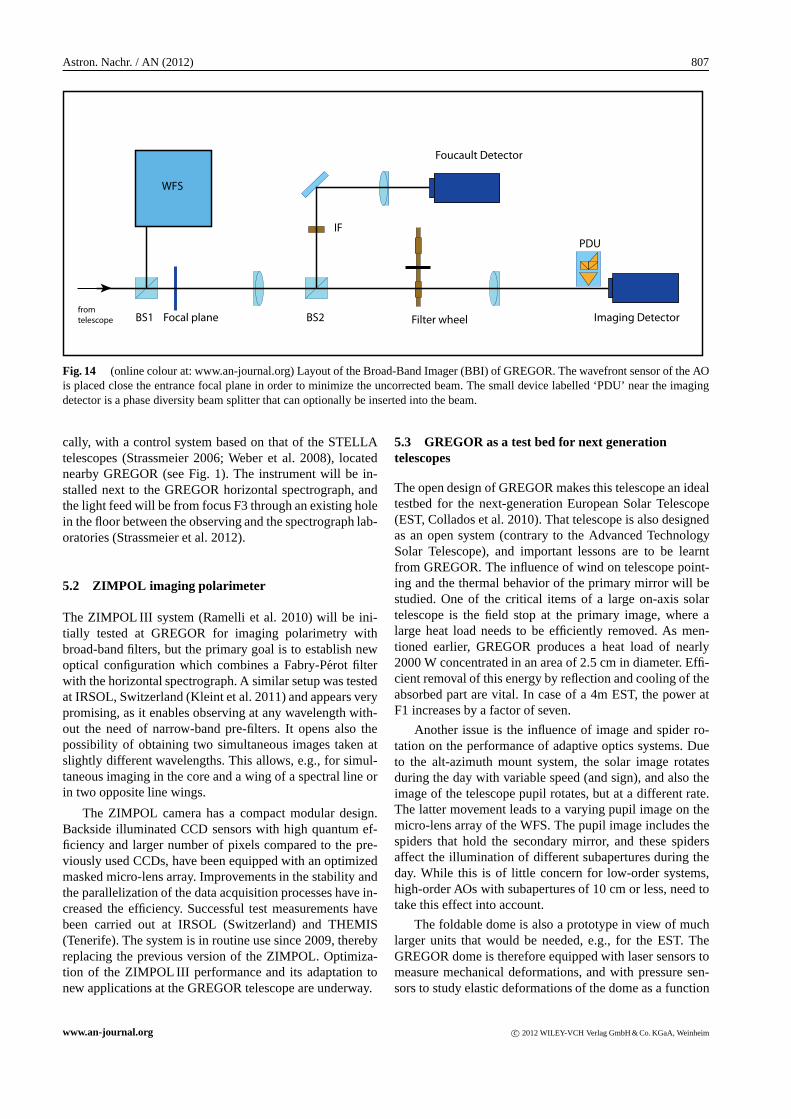
4.3 Broad-band imager
The Broad-Band Imager (BBI, von der Luhe et al. 2012)is designed to take filtergrams at visible wavelengths, downto 390 nm with a field of view of 120′′×80′′, and with apixel scale that allows for diffraction-limited imaging, usingpost-facto reconstruction techniques. Sequences taken withthis instrument will be used to investigate e.g. the fine struc-ture of photospheric granulation (Steiner et al. 2010). TheBBI is equipped with a PCO4000 camera with 4008×2672
pixels. A second channel of the BBI is used for Foucaulttests to monitor the alignment and optical quality of thetelescope. The BBI has been set up by KIS, using mostlyexisting hardware from the VTT. Figure 14 shows the opti-cal layout of the instrument. The BBI either takes bursts ofshort-exposure images to allow for post-facto image recon-struction, or it employs a phase-diversity (PD) beam splitterto record simultaneously focused and defocused images forPD reconstruction. Figure 2 is one of the first images takenwith the BBI, reconstructed using speckle interferometry.
4.4 Multi-instrument measurements
The arrangement of the focal-plane instruments in the ob-serving laboratory is such that at least two of them canbe used simultaneously to observe the same field of view.The light distribution scheme shown in Fig. 13 allows suchmulti-instrument observations without compromising thephoton flux to the respective instrument. Simultaneous ob-servations in different spectral lines, from the near UV, up
www.an-journal.org c© 2012 WILEY-VCH Verlag GmbH & Co. KGaA, Weinheim

806 W. Schmidt et al.: GREGOR
5:95
beam splitter
blue -red
beam splitter
from telescope
IR - VIS
beam
splitter
GRISBlue channel
Broad Narrow
(planned)
Narrow-band
polarimetric channel (red) Broad-band
channel (red)
Filter
slider
Collimator
Reimaging
lens
FPI 1
FPI 2
CCD
R1
CCD
R2
CCD
B1
CCD
B2
Polarimeter
Wavefront
sensor
slit jaw
camera
Slit
Fig. 13 (online colour at: www.an-journal.org) Scheme of the GREGOR Fabry Perot Interferometer and the light distribution system.Light from the telescope enters from below. A beam splitter sends a small fraction of the light to the wavefront sensor of the AO. Then, adichroic beam splitter transmits the infrared light to GRIS and the slit jaw camera, and reflects the visible wavelength band to the GFPI.A blue/red beam splitter deflects the blue part of the light to the blue channel, and the remaining light enters the GFPI, where it is splitwith a ratio of 5:95 between the broad and the narrow (spectro-polarimetric) channel.
to, say 2.2 μm, provide three-dimensional information ofthe dynamics and the magnetic field of the photosphereand the lower and mid chromosphere. The combination ofGRIS, a grating instrument with a scan unit, and the GFPI, afilter-based spectro-polarimeter will combine the strengthsof both systems. The combined measurements will be si-multaneous, but not necessarily synchronized, so that eachinstrument can optimize the integration time according tothe photon flux of the observed line and the required signal-to-noise ratio. Similar setups are possible for the Broad-Band Imager (BBI, see Sect. 4.3) and any future instrumentthat would be located nearby.
5 Second-generation instruments andoutlook
5.1 GREGOR@Night
Night-time stellar observations with GREGOR open a newdimension of solar physics. If we study the properties of
“solar twins” in the Milky Way, we will better understandthe long-term behavior of our Sun, including the relation be-tween magnetic activity and irradiance. To this end, we haveto observe a sufficiently large number of stars that are verysimilar to the Sun, but are in different states of their evolu-tion. The similarity with the Sun includes the spectral type,and the magnetic activity. GREGOR with its 1.5 m aper-ture is well suited for this purpose, since a large number ofnights can be used for this solar twin program. From stellarstatistics one estimates the existence of about 5 billions ofG2V stars in the Milky Way, or about 3000 such solar twinswithin a radius of 250 light years around the Sun (Strass-meier et al. 2007).
The instrument foreseen for GREGOR is an Echellespectrograph based on the SOFIN instrument of the NordicOptical Telescope, with a spectral resolution up to � =
87 000, covering a wavelength range from 350 nm to1130 nm. For wavelength calibration in the spectral regionbetween 500 nm and 600 nm, an iodine cell can be used. Thespectrograph and the telescope will be operated automati-
c© 2012 WILEY-VCH Verlag GmbH & Co. KGaA, Weinheim www.an-journal.org
Astron. Nachr. / AN (2012) 807
Foucault Detector
Imaging Detector
PDU
WFS
Focal plane
IF
Filter wheelBS2BS1from
telescope
Fig. 14 (online colour at: www.an-journal.org) Layout of the Broad-Band Imager (BBI) of GREGOR. The wavefront sensor of the AOis placed close the entrance focal plane in order to minimize the uncorrected beam. The small device labelled ‘PDU’ near the imagingdetector is a phase diversity beam splitter that can optionally be inserted into the beam.
cally, with a control system based on that of the STELLAtelescopes (Strassmeier 2006; Weber et al. 2008), locatednearby GREGOR (see Fig. 1). The instrument will be in-stalled next to the GREGOR horizontal spectrograph, andthe light feed will be from focus F3 through an existing holein the floor between the observing and the spectrograph lab-oratories (Strassmeier et al. 2012).
5.2 ZIMPOL imaging polarimeter
The ZIMPOL III system (Ramelli et al. 2010) will be ini-tially tested at GREGOR for imaging polarimetry withbroad-band filters, but the primary goal is to establish newoptical configuration which combines a Fabry-Perot filterwith the horizontal spectrograph. A similar setup was testedat IRSOL, Switzerland (Kleint et al. 2011) and appears verypromising, as it enables observing at any wavelength with-out the need of narrow-band pre-filters. It opens also thepossibility of obtaining two simultaneous images taken atslightly different wavelengths. This allows, e.g., for simul-taneous imaging in the core and a wing of a spectral line orin two opposite line wings.
The ZIMPOL camera has a compact modular design.Backside illuminated CCD sensors with high quantum ef-ficiency and larger number of pixels compared to the pre-viously used CCDs, have been equipped with an optimizedmasked micro-lens array. Improvements in the stability andthe parallelization of the data acquisition processes have in-creased the efficiency. Successful test measurements havebeen carried out at IRSOL (Switzerland) and THEMIS(Tenerife). The system is in routine use since 2009, therebyreplacing the previous version of the ZIMPOL. Optimiza-tion of the ZIMPOL III performance and its adaptation tonew applications at the GREGOR telescope are underway.
5.3 GREGOR as a test bed for next generationtelescopes
The open design of GREGOR makes this telescope an idealtestbed for the next-generation European Solar Telescope(EST, Collados et al. 2010). That telescope is also designedas an open system (contrary to the Advanced TechnologySolar Telescope), and important lessons are to be learntfrom GREGOR. The influence of wind on telescope point-ing and the thermal behavior of the primary mirror will bestudied. One of the critical items of a large on-axis solartelescope is the field stop at the primary image, where alarge heat load needs to be efficiently removed. As men-tioned earlier, GREGOR produces a heat load of nearly2000 W concentrated in an area of 2.5 cm in diameter. Effi-cient removal of this energy by reflection and cooling of theabsorbed part are vital. In case of a 4m EST, the power atF1 increases by a factor of seven.
Another issue is the influence of image and spider ro-tation on the performance of adaptive optics systems. Dueto the alt-azimuth mount system, the solar image rotatesduring the day with variable speed (and sign), and also theimage of the telescope pupil rotates, but at a different rate.The latter movement leads to a varying pupil image on themicro-lens array of the WFS. The pupil image includes thespiders that hold the secondary mirror, and these spidersaffect the illumination of different subapertures during theday. While this is of little concern for low-order systems,high-order AOs with subapertures of 10 cm or less, need totake this effect into account.
The foldable dome is also a prototype in view of muchlarger units that would be needed, e.g., for the EST. TheGREGOR dome is therefore equipped with laser sensors tomeasure mechanical deformations, and with pressure sen-sors to study elastic deformations of the dome as a function
www.an-journal.org c© 2012 WILEY-VCH Verlag GmbH & Co. KGaA, Weinheim
808 W. Schmidt et al.: GREGOR
of wind speed and direction (Sliepen et al. 2010). It shouldbe mentioned that the open GREGOR telescope, togetherwith its retractable dome, will inevitably lead to dust depo-sition on the primary mirror.
5.4 Next steps
The ongoing science verification phase will reveal strengthsand weaknesses of the new telescope, which in turn will leadto improvements. This is a continuous process that will notend when GREGOR becomes available for regular scientificobservations in the near future.
Acknowledgements. The 1.5 m GREGOR solar telescope wasbuild by a German consortium under the leadership of theKiepenheuer-Institut fur Sonnenphysik in Freiburg with theLeibniz-Institut fur Astrophysik Potsdam, the Institut fur Astro-physik Gottingen, and the Max-Planck-Institut fur Sonnensystem-forschung in Katlenburg-Lindau as partners, and with contribu-tions by the Instituto de Astrofısica de Canarias and the Astronom-ical Institute of the Academy of Sciences of the Czech Republic.
References
Ball, W.T., Unruh, Y.C., Krivova, N.A., Solanki, S., Harder, J.W.:2011, A&A 530, A71
Ball, W.T., Unruh, Y.C., Krivova, N.A., Solanki, S., Wenzler, T.,Mortlock, D.J., Jaffe, A.H.: 2012, A&A 541, A27
Balthasar, H., Bello Gonzalez, N., Collados, et al.: 2011, in: J.R.Kuhn, S. V. Berdyugina, D.M. Harrington, S.L. Keil, H. Lin,T. Rimmele, J. Trujillo-Bueno (eds.), Solar Polarization Work-shop 6, ASPC 437, p. 351
Barthol, P., Gandorfer, A., Solanki, S.K., et al.: 2011, Sol. Phys.268, 1
Bello Gonzalez, N., Franz, M., Martınez Pillet, V., Bonet, J.A.,Solanki, S.K., del Toro Iniesta, J.C., Schmidt, W., et al.: 2010,ApJ 723, L134
Berkefeld, T., Soltau, D., von der Luhe, O.: 2006, in: B.L. Eller-broek, D. Bonaccini Calia (eds.), Advances in Adaptive OpticsII, SPIE 6272, p. 627205
Berkefeld, T., Soltau, D., Schmidt, D., von der Luhe, O.: 2010,Appl.Optics 49, G155
Berkefeld, Th., Schmidt, D., Soltau, D., von der Luhe, O., Hei-decke, F.: 2012, AN 333, 863
Bharti, L., Joshi, C., Jaaffrey, S.N.A., Jain, R.: 2009, MNRAS 393,65
Cao, W., Gorceix, N., Coulter, R., Coulter, A., Goode, P.R.: 2010,in: L.M. Stepp, R. Gilmozzi, H.J. Hall (eds.), Ground-Basedand Airborne Instrumentation for Astronomy III, SPIE 7733, p.773330
Carlsson, M.: 2007, in: P. Heinzel, I. Dorotovic, R.J. Rutten (eds.),The Physics of Chromospheric Plasmas, ASPC 368, p. 49
Collados, M., Lagg, A., Dıaz Garcı A, J.J., Hernandez Suarez,E., Lopez Lopez, R., Paez Mana, E., Solanki, S.K.: 2007, in:P. Heinzel, I. Dorotovic, R.J. Rutten (eds.), The Physics of Chro-mospheric Plasmas, ASPC 368, p. 611
Collados, M., Calcines, A., Dıaz, J.J., Hernandez, E., Lopez, R.,Paez, E.: 2008, in: I.S. McLean, M.M. Casali (eds.), Ground-Based and Airborne Instrumentation for Astronomy II, SPIE7014, p. 70145Z
Collados, M., Bettonvil, F., Cavaller, L., et al.: 2010, AN 331, 615
Collados, M., Lopez, R., Paez, E., et al.: 2012, AN 333, 872Denker, C., von der Luhe, O., Feller, A., et al.: 2012, AN 333, 810de Wijn, A.G., Stenflo, J.O., Solanki, S.K., Tsuneta, S.: 2009,
Space Sci.Rev. 144, 275Engvold, O., Andersen, T.: 1990, LEST Foundation Design ReportFranz, M., Schlichenmaier, R.: 2009, A&A 508, 1453Frohlich, C.: 2006, Space Sci.Rev. 125, 53Fugner, D., Granzer, T., Strassmeier, K.G.: 2011, in: C. Johns-
Krull, M.K. Browning, A.A. West (eds.), Cool Stars, StellarSystems, and the Sun, ASPC 448, p. 863
Granzer, T., Halbgewachs, C., Volkmer, R., Soltau, D.: 2012, AN333, 823
Grossmann-Doerth, U., Schussler, M., Steiner, O.: 1998, A&A337, 928
Halbgewachs, C., Caligari, P., Glogowski, K., et al.: 2012, AN 333,840
Hammerschlag, R.H., Kommers, J.N., Visser, S., et al.: 2012, AN333, 830
Harder, J., Fontenla, J., White, O., Rottman, G., Woods, T.: 2005,Mem. Soc. Astron. Ital. 76, 735
Hasan, S.S., van Ballegooijen, A.A., Kalkofen, W., Steiner, O.:2005, ApJ 631, 1270
Harvey, J.W.: 2009, in: S.V. Berdyugina, K.N. Nagendra,R. Ramelli (eds.), Solar Polarization 5: In Honor of Jan Stenflo,ASPC 405, p. 157
Hofmann, A., Arlt, K., Balthasar, H., et al.: 2012, AN 333, 854Joshi, J., Pietarila, A., Hirzberger, J., Solanki, S.K., Aznar
Cuadrado, R., Merenda, L.: 2011, ApJ 740, L55Judge, P., Knolker, M., Schmidt, W., Steiner, O.: 2010, ApJ 720,
776Keil, S.L., Rimmele, T.R., Wagner, J., ATST team: 2010, AN 331,
609Kleint, L., Feller, A., Gisler, D.: 2011, A&A 529, A78Kneer, F.: 2012, AN 333, 790Kosugi, T., Matsuzaki, K., Sakao, T., et al.: 2007, Sol. Phys. 243,
3Krivova, N.A., Solanki, S.K., Fligge, M., Unruh, Y.C.: 2003, A&A
399, L1Krivova, N.A., Solanki, S.K., Floyd, L.: 2006, A&A 452, 631Lagg, A., Solanki, S.K., Riethmuller, T.L., et al.: 2010, ApJ 723,
L164Lofdahl, M.G.: 2002, in: P.J. Bones, M.A. Fiddy, R.P. Millane
(eds.), Image Reconstruction from Incomplete Data, SPIE 4792,p. 146
Penn, M.J., Livingston, W.: 2011, in: D. Choudhary, K.G. Strass-meier (eds.), The Physics of Sun and Star Spots, IAU Symp.273, p. 126
Puschmann, K.G., Sailer, M.: 2006, A&A 454, 1011Puschmann, K.G., Balthasar, H., Bauer, S.-M., et al.: 2012a, ASPC
463, astro-ph/1111.5509Puschmann, K.G., Balthasar, H., Bello Gonzalez, N., et al.: 2012b,
astro-ph/1207.2084Puschmann, K.G., Denker, C., Kneer, F., et al.: 2012c, AN 333,
880Ramelli, R., Balemi, S., Bianda, M., et al.: 2010, in: I.S. McLean,
S.K. Ramsay, H. Takami (eds.), Ground-based and Airborne In-strumentation for Astronomy III, SPIE 7735, p. 77351Y
Rezaei, R., Beck, C., Schmidt, W.: 2012a, A&A 541, A60Rezaei, R., Bello Gonzalez, N., Schlichenmaier, R.: 2012b, A&A
537, A19Riethmuller, T.L., Solanki, S.K., Lagg, A.: 2008, ApJ 678, L157
c© 2012 WILEY-VCH Verlag GmbH & Co. KGaA, Weinheim www.an-journal.org
Astron. Nachr. / AN (2012) 809
Riethmuller, T.L., Solanki, S.K., Martınez Pillet, V.: 2010, ApJ723, L169
Rutten, R.J.: 2010, Mem. Soc. Astron. Ital. 81, 565Scharmer, G.B., Gudiksen, B.V., Kiselman, D., Lofdahl, M.G.,
Rouppe van der Voort, L.H.M.: 2002, Nature 420, 151Scharmer, G.B., Henriques, V.M.J., Kiselman, D., de la Cruz
Rodrıguez, J.: 2011, Sci 333, 316Scharmer, G.B., Kiselman, D., Lofdahl, M.G., Rouppe van der
Voort, L.H.M.: 2003, in: J. Trujillo-Bueno, J. Sanchez Almeida(eds.), Solar Polarization, ASPC 307, p. 3
Scherrer, P.H., Bogart, R.S., Bush, R.I., et al.: 1995, Sol. Phys.162, 129
Scherrer, P.H., Schou, J., Bush, R.I., et al.: 2012, Sol. Phys. 275,207
Schmidt, D., Berkefeld, T., Feger, B., Heidecke, F.: 2010a, in: B.L.Ellerbroek, M. Hart, N. Hubin, P.L. Wizinowich (eds.), Adap-tive Optics Systems II, SPIE 7736, p. 773607
Schmidt, W., Solanki, S.K., Barthol, P., et al.: 2010b, AN 331, 601Schmidt, W., von der Luhe, O., Volkmer, R., et al.: 2012, astro-
ph/1202.4289Schussler, M., Vogler, A.: 2006, ApJ 641, L73Sliepen, G., Jagers, A.P.L., Hammerschlag, R.H., Bettonvil,
F.C.M.: 2010, in: L.M. Stepp, R. Gilmozzi, H.J. Hall (eds.),Ground-Based and Airborne Telescopes III, SPIE 7733, p.773332
Solanki, S.K., Barthol, P., Danilovic, S., et al.: 2010, ApJ 723,L127
Soltau, D., Volkmer, R., von der Luhe, O., Berkefeld, Th.: 2012,AN 333, 847
Spruit, H.C., Scharmer, G.B.: 2006, A&A 447, 343Steiner, O., Franz, M., Bello Gonzalez, N., et al.: 2010, ApJ 723,
L180
Strassmeier, K.G.: 2006, Ap&SS 304, 397Strassmeier, K.G., Woche, M., Granzer, T., Andersen, M.I.,
Schmidt, W., Koubsky, P.: 2007, in: F. Kneer, K.G. Puschmann,A.D. Wittmann (eds.), Modern Solar Facilities – Advanced So-lar Science, p. 51
Strassmeier, K.G., Ilyin, I.V., Woche, M., et al.: 2012, AN 333,901
Volkmer, R., von der Luhe, O., Kneer, F., et al.: 2006, in: L.M.Stepp (ed.), Ground-Based and Airborne Telescopes, SPIE6267, p. 62670W
Volkmer, R., Eisentrager, P., Emde, P., et al.: 2012, AN 333, 816von der Luhe, O., Schmidt, W., Soltau, D., Kneer, F., Staude, J.:
2000, in: A. Wilson (ed.), The Solar Cycle and Terrestrial Cli-mate, Solar and Space weather, ESA-SP 463, p. 629
von der Luhe, O., Berkefeld, T., Soltau, D.: 2005, Comptes RendusPhysique 6, 1139
von der Luhe, O., Volkmer, R., Kentischer, T.J., Geißler, R.: 2012,AN 333, 894
Weber, M., Granzer, T., Strassmeier, K.G., Woche, M.: 2008, in:A. Bridger, N.M. Radziwill (eds.), Advanced Software and Con-trol for Astronomy II, SPIE 7019, p. 70190L
Wedemeyer-Bohm, S., Lagg, A., Nordlund, A.: 2009,Space Sci.Rev. 144, 317
Wedemeyer-Bohm, S., Scullion, E., Steiner, O., Rouppe van derVoort, L., de La Cruz Rodriguez, J., Fedun, V., Erdelyi, R.:2012, Nature 486, 505
Wenzler, T., Solanki, S.K., Krivova, N.A., Frohlich, C.: 2006,A&A 460, 583
Woger, F., von der Luhe, O.: 2008, in: in: A. Bridger, N.M. Radzi-will (eds.), Advanced Software and Control for Astronomy II,SPIE 7019, p. 70191E
Woods, T.N., Rottman, G.: 2005, Sol. Phys. 230, 375
www.an-journal.org c© 2012 WILEY-VCH Verlag GmbH & Co. KGaA, Weinheim