the study of swimming propulsion using computational fluid dynamics
158
DANIEL ALMEIDA MARINHO THE STUDY OF SWIMMING PROPULSION USING COMPUTATIONAL FLUID DYNAMICS A three-dimensional analysis of the swimmer’s hand and forearm Universidade de Trás-os-Montes e Alto Douro Vila Real, Portugal, 2009
Transcript of the study of swimming propulsion using computational fluid dynamics
DANIEL ALMEIDA MARINHO
THE STUDY OF SWIMMING PROPULSION USING
COMPUTATIONAL FLUID DYNAMICS
A three-dimensional analysis of the
swimmer’s hand and forearm
Universidade de Trás-os-Montes e Alto Douro
Vila Real, Portugal, 2009
UNIVERSIDADE DE TRÁS-OS-MONTES E ALTO DOURO
DANIEL ALMEIDA MARINHO
THE STUDY OF SWIMMING PROPULSION USING
COMPUTATIONAL FLUID DYNAMICS
A three-dimensional analysis of the swimmer’s hand and forearm
PhD in Sport Sciences
Promoters: Professor António José Silva
Professor Abel Rouboa
Vila Real, Portugal, 2009
I
Este trabalho foi expressamente elaborado com vista à obtenção do grau de Doutor em
Ciências do Desporto, de acordo com o disposto no Decreto-lei n.º 216/92, de 13 de
Outubro.
II

This thesis was supported by the Portuguese Government by a grant of the Science and
Technology Foundation (SFRH/BD/25241/2005).
III

To Tia Belinha
IV
Acknowledgments
The present thesis was only possible to be developed with the important help of so
many people, who had a significant contribution to this final work. Many thanks to all
of them.
I would like to express my deepest appreciation to Professor António José Silva,
promoter of this thesis, for providing his scientific knowledge, for guiding this scientific
research, as well as for his encouragement during the whole project. To ToZé, my
gratitude for believing in me and in my work, for his support, help and friendship.
To Professor Abel Rouboa, promoter of this thesis, for his important contribution during
the whole project. My sincere appreciation for his friendship, for helping me with the
theoretical part of the CFD methodology and for the important collaboration in the
writing of the papers.
To Professor Victor Reis, for his important remarks and cooperation during all phases
of this project, especially reviewing all the papers and the final form of the thesis. To
Victor, I would also like to thank for helping me since the first meeting we had in Vila
Real and for his constant support and friendship.
To Professor João Paulo Vilas-Boas, Professor Francisco Alves, Professor Leandro
Machado and Professor Per-Ludvik Kjendlie, for their important remarks, corrections
and suggestions to improve this project.
To my friends Luciano Sousa and Luís Leal, for their cooperation and significant help
during the numerical simulation procedures.
To my colleagues and friends Mário Marques, Aldo Costa, Pedro Guedes de Carvalho,
Tiago Barbosa and Nuno Garrido, for their encouragement and support in everything I
V

needed. To Mário, special thanks for our discussions and valuable remarks during our
trips and for being always interested in the progress of this thesis.
Sincere thanks to all the swimming team of Clube Fluvial Vilacondense. Many thanks
to António Vasconcelos (Tonas), Daniel Novais and Catarina Figueiredo, for their
cooperation and interest and for allowing the necessary free time for developing this
thesis.
Sincere thanks to the swimmer Adriano Niz, for volunteering to participate in this work.
I would like to thank the staff of the Radiology Department of Hospital de São João,
Porto, and personally to the Department Director, Professor Isabel Ramos, for helping
with the computer tomography scans procedures, allowing to obtain the geometry of the
swimmer’s hand and forearm.
I would also like to express my gratitude to the Med Mat Innovation Company, Maia,
especially to Professor José Domingos Santos and to Engineer Bruno Sá, for their
contributes to the design of the digital model of the swimmer’s hand and forearm.
Many thanks to all my friends.
Finally, I wish to express my sincere gratitude to all my family, especially my parents
and my sisters, for encouraging and supporting me during all my life, for being present
when I needed them, for understanding and admiring my work; for everything!
VI
Abstract
The main purpose of the present thesis was to study the mechanism of swimming propulsion using
Computational Fluid Dynamics (CFD) through a three-dimensional analysis of the swimmer’s hand and
forearm.
CFD methodology is a branch of fluid mechanics that solves and analyses problems involving a fluid
flow by means of computer-based simulations. This methodology can be considered as an interesting
approach to use in swimming research, since it allows simulating the water flow around the human body
and thus, to analyse the propulsive forces produced by the swimmer.
The first part of this thesis was to be able to apply CFD using a three-dimensional model of the swimmer
body. After the propulsive force measurements using a true three-dimensional model of a human segment
have been demonstrated, it was possible to improve previous CFD analysis, including a more realistic
model of the swimmer hand and forearm. Additionally, the CFD methodology was applied to address
some practical concerns of swimmers and coaches, such as the finger’s relative position during the
underwater path of the stroke cycle.
The main conclusions of the present thesis were: (i) the drag coefficient was the main responsible for the
hand and forearm propulsion, with a maximum value of force corresponding to an angle of attack of 90º;
(ii) an important contribution of the lift force to the overall force generation by the hand/forearm in
swimming phases was observed at angles of attack of 30º, 45º and 60º, especially when the little finger
leads the motion; (iii) the hand model with the thumb adducted presented higher values of drag
coefficient compared with thumb abducted models. The model with the thumb fully abducted allowed
increasing the lift coefficient of the hand at angles of attack of 0º and 45º; (iv) the resultant force
coefficient showed that the hand model with the thumb fully abducted presented higher values than the
positions with the thumb partially abducted and adducted at angles of attack of 0º and 45º. At an angle of
attack of 90º, the model with the thumb adducted presented the highest value of resultant force
coefficient; (v) the hand model with little distance between fingers presented higher values of drag
coefficient than the models with fingers closed and fingers with large distance spread. The values for the
lift coefficient presented little differences between the models with different finger’s spreading and; (vi)
the results suggested that for hand positions in which the lift force can play an important role, the
abduction of the thumb may be better, whereas at higher angles of attack, in which the drag force is
dominant, the adduction of the thumb may be preferable. Furthermore, it is suggested that fingers slightly
spread could allow the hand to create more force during swimming.
VII
Resumo
O objectivo principal da presente dissertação foi estudar o mecanismo propulsivo em natação, utilizando a
Dinâmica Computacional de Fluidos (DCF) através de uma análise tridimensional da mão e antebraço do
nadador.
A metodologia de DCF baseia-se na simulação computacional do escoamento do fluido em torno de
estruturas físicas. Esta metodologia pode ser considerada como uma forma interessante para ser utilizada
na investigação em natação, tornando possível a simulação do escoamento da água em torno do nadador
e, desta forma, analisar as forças propulsivas produzidas pelo nadador.
A primeira parte desta dissertação foi dedicada à aplicação da DCF utilizando um modelo tridimensional
do corpo do nadador. Após ter sido demonstrada a possibilidade de se analisar as forças propulsivas
usando um modelo tridimensional de um segmento humano, foi possível melhorar as análises numéricas
anteriormente efectuadas, incluindo um modelo mais real da mão e antebraço do nadador. Para além
disso, a metodologia de DCF foi aplicada para tentar responder a algumas questões mais práticas de
nadadores e treinadores, tais como a posição relativa dos dedos durante o trajecto motor em natação.
As conclusões da presente dissertação foram as seguintes: (i) o coeficiente de arrasto foi o principal
responsável pela produção de força pela mão e antebraço, apresentando o valor mais elevado com um
ângulo de ataque de 90º; (ii) foi observada uma importante contribuição da força de sustentação para a
produção de força pela mão e antebraço, com ângulos de ataque de 30º, 45º e 60º, especialmente quando o
dedo mínimo actuava como bordo de ataque; (iii) o modelo da mão com o polegar em adução apresentou
valores superiores no coeficiente de arrasto do que os modelos com o polegar em abdução. O modelo com
o polegar totalmente em abdução permitiu aumentar o coeficiente de sustentação da mão, com ângulos de
ataque de 0º e 45º; (iv) o modelo da mão com o polegar totalmente em abdução apresentou valores
superiores no coeficiente de força resultante do que as posições com o polegar parcialmente em abdução e
em adução, com ângulos de ataque de 0º e 45º. Com um ângulo de ataque de 90º, o modelo com o polegar
em adução apresentou o valor do coeficiente de força resultante mais elevado; (v) o modelo da mão com
uma pequena distância entre os dedos apresentou valores do coeficiente de arrasto mais elevados do que
os modelos com os dedos juntos e com uma maior distância entre os dedos. Os valores do coeficiente de
sustentação apresentaram pequenas diferenças entre os modelos com diferente espaçamento entre os
dedos e; (vi) os resultados apresentados sugerem que, nas posições da mão nas quais a força de
sustentação pode desempenhar um importante papel, a abdução do polegar pode ser benéfica, enquanto
que, com ângulos de ataque mais elevados, nos quais a força de arrasto é dominante, a adução do polegar
parece ser preferível. Adicionalmente, foi também sugerido que um pequeno afastamento dos dedos pode
permitir à mão criar mais força durante o nado.
VIII
Table of contents
Acknowledgments...........................................................................................................V
Abstract ........................................................................................................................VII
Resumo ........................................................................................................................VIII
Table of contents........................................................................................................... IX
List of tables ....................................................................................................................X
List of figures ................................................................................................................ XI
General introduction .................................................................................................... 14
Study 1
The hydrodynamic drag during the gliding in swimming .......................................... 20
Study 2
The use of Computational Fluid Dynamics in swimming research............................ 31
Study 3
Design of a three-dimensional hand/forearm model to apply Computational Fluid
Dynamics .................................................................................................................... 40
Study 4
Computational analysis of the hand and forearm propulsion in swimming............... 50
Study 5
Hydrodynamic analysis of different thumb positions in swimming .......................... 64
Study 6
Swimming propulsion forces are enhanced by a small finger spread ........................ 83
Review
Swimming simulation: a new tool for swimming research and practical applications
.................................................................................................................................... 95
Main conclusions ........................................................................................................ 136
References ................................................................................................................... 139
Appendix .............................................................................................................CXLVIII
IX
List of tables
Study 1
Table 1: Drag coefficient values and contribution of pressure and skin friction drag for the total drag to
each velocity and for the two different gliding positions. .................................................................25
Study 2
Table 1: Values of CD and CL of the hand/forearm segment as a function of pitch angle. Sweep back angle
= 0º and flow velocity = 2.00 m/s. ....................................................................................................36
X
List of figures
Study 1
Figure 1: Swimmer’s model geometry with the surfaces meshed using Gambit. An example for the
position with the arms along the trunk is presented. .........................................................................22 Figure 2: Computational fluid dynamics model geometry with the swimmer with the arms extended at the
front. The water depth is 1.80 m, the width is 2.50 m and the length is 8.0 m. ................................24 Figure 3: Relationship between the drag coefficient and the velocity for the two different gliding
positions. The regression equations and the R2 values are also presented. .......................................26
Study 2
Figure 1: Hand and forearm model inside the domain with 3-D mesh of cells. .........................................34 Figure 2: Computational vision of the relative pressure contours on the hand/forearm surfaces. ..............35
Study 3
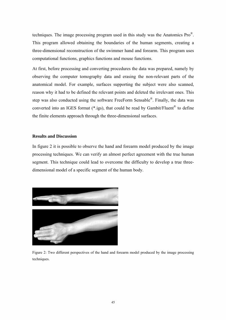
Figure 1: Computer tomography scans protocol. .......................................................................................44 Figure 2: Two different perspectives of the hand and forearm model produced by the image processing
techniques. ........................................................................................................................................45 Figure 3: Hand and forearm model inside the domain with three-dimensional mesh of cells....................47 Figure 4: Computational vision of the relative pressure contours on the hand/forearm surfaces. ..............48
Study 4
Figure 1: Three-dimensional reconstruction of the swimmer hand and forearm. The boundaries of the
human segments were obtained by the computer tomography scans................................................53 Figure 2: Hand and forearm model inside the three-dimensional domain. The whole domain was meshed
with 900 thousand cells.....................................................................................................................55 Figure 3: Progressive mesh of the hand and forearm model. Adaptive meshing was used to achieve
optimum mesh refinement. ...............................................................................................................55 Figure 4: Computational fluid dynamics oil-film plot shows the direction of the water flow in the wake of
the model. The flow path line at a 90º angle of attack of the hand and forearm segment is presented
(sweep back angle = 0º). ...................................................................................................................56 Figure 5: Drag and lift coefficients vs. flow velocity for each angle of attack. Sweep back angle = 0º.....57 Figure 6: Drag and lift coefficients vs. flow velocity for each angle of attack. Sweep back angle = 90º...57 Figure 7: Drag and lift coefficients vs. flow velocity for each angle of attack. Sweep back angle = 180º.58 Figure 8: Drag coefficient vs. angle of attack for each sweep back angle (SA). Flow velocity = 2.0 m/s. 59 Figure 9: Lift coefficient vs. angle of attack for each sweep back angle (SA). Flow velocity = 2.0 m/s. ..59
XI
Study 5
Figure 1: The models of the hand with the thumb in different positions: fully abducted, partially abducted
and adducted. ....................................................................................................................................68 Figure 2: The model of the hand with the thumb fully abducted inside the domain (Angle of attack = 0º,
Sweepback angle = 0º)......................................................................................................................70 Figure 3: The angle of attack (Schleihauf, 1979). The arrow represents the direction of the flow. ...........71 Figure 4: The sweep back angle (Schleihauf, 1979). The arrows represent the direction of the flow........71 Figure 5: Drag and lift coefficients vs. flow velocity for each angle of attack in the position with the
thumb fully abducted. .......................................................................................................................72 Figure 6: Drag and lift coefficients vs. flow velocity for each angle of attack in the position with the
thumb partially abducted...................................................................................................................73 Figure 7: Drag and lift coefficients vs. flow velocity for each angle of attack in the position with the
thumb adducted.................................................................................................................................73 Figure 8: Values of drag coefficient obtained for the different angles of attack and for the different thumb
positions. Sweepback angle = 0º and flow velocity = 2.0 m/s. .........................................................74 Figure 9: Values of lift coefficient obtained for the different angles of attack and for the different thumb
positions. Sweepback angle = 0º and flow velocity = 2.0 m/s. .........................................................75 Figure 10: Values of the resultant force coefficient obtained for the different angles of attack and for the
different thumb positions. Sweepback angle = 0º and flow velocity = 2.0 m/s. ...............................75
Study 6
Figure 1: Anthropometric characteristics of the swimmer hand. Hand length (1): 20.20 cm, index breadth
(2): 1.50 cm, index length (3): 8.10 cm, palm length (4): 9.50 cm, hand breadth (5): 8.90 cm. .......86 Figure 2: Computational fluid dynamics model geometry with the hand inside the domain (model with
fingers closed)...................................................................................................................................87 Figure 3: Values of CD obtained for the different attack angles and for the different finger spread.
Sweepback angle = 0º and flow velocity = 2.0 m/s. .........................................................................89 Figure 4: Values of CL obtained for the different attack angles and for the different finger spread.
Sweepback angle = 0º and flow velocity = 2.0 m/s. .........................................................................90
Review
Figure 1: Hydrodynamic drag force of the swimmer, the digital CFD model and the mannequin. Adapted
from Bixler et al. (2007). ................................................................................................................108 Figure 2: The angle of attack (Schleihauf, 1979). The arrow represents the direction of the flow. .........111 Figure 3: The sweep back angle (Schleihauf, 1979). The arrows represent the direction of the flow......111 Figure 4: Drag coefficient vs. angle of attack for the digital model of the hand, forearm and hand/forearm
(Sweep back angle = 0º). Adapted from Bixler and Riewald (2002). .............................................111 Figure 5: Lift coefficient vs. angle of attack for the digital model of the hand, forearm and hand/forearm
(Sweep back angle = 0º). Adapted from Bixler and Riewald (2002). .............................................112
XII
Figure 6: Drag and lift coefficient of the hand/forearm model for angles of attack of 0º, 45º and 90º (SA:
Sweep back angle). Flow velocity = 2.0 m/s. Adapted from Silva et al. (2008a). ..........................113 Figure 7: The hand and forearm model used by Silva et al. (2008a) inside the three-dimensional CFD
domain. ...........................................................................................................................................113 Figure 8: Comparison between steady and accelerated drag and lift coefficients for angles of attack of 0º,
90º and 180º (Sweep back angle = 0º). Adapted from Rouboa et al. (2006)...................................115 Figure 9: Drag coefficient for angles of attack of 0º, 45º and 90º for the different thumb positions (Sweep
back angle = 0º, Flow velocity = 2.0 m/s). Adapted from Marinho et al. (2008d). ........................118 Figure 10: Lift coefficient for angles of attack of 0º, 45º and 90º for the different thumb positions (Sweep
back angle = 0º, Flow velocity = 2.0 m/s). Adapted from Marinho et al. (2008d). ........................119 Figure 11: Drag coefficient for angles of attack of 0º, 15º, 30º, 45º, 60º, 75º and 90º for the different finger
spread positions (Sweep back angle = 0º, Flow velocity = 2.0 m/s). Adapted from Marinho et al.
(2008e)............................................................................................................................................120 Figure 12: Lift coefficient for angles of attack of 0º, 15º, 30º, 45º, 60º, 75º and 90º for the different finger
spread positions (Sweep back angle = 0º, Flow velocity = 2.0 m/s). Adapted from Marinho et al.
(2008e)............................................................................................................................................121 Figure 13: Momentum reduction in an average second of two types of kicking movements (large/slow vs.
small/fast). Adapted from Lyttle and Keys (2006). ........................................................................122 Figure 14: The model used by Marinho et al. (2008a) in a ventral position with the arms alongside the
trunk inside the CFD domain. .........................................................................................................123 Figure 15: The model used by Marinho et al. (2008a) in a ventral position with the arms extended at the
front, with the shoulders fully flexed, inside the CFD domain. ......................................................123 Figure 16: Two-dimensional model used by Silva et al. (2008b) to determine the effect of drafting
distances on hydrodynamic drag.....................................................................................................125 Figure 17: Relationship between total drag, skin-friction drag and pressure drag and the gliding velocity
for the positions with the arms alongside the trunk (AAT) and with the arms extended at the front
with the shoulders flexed (AEF). Adapted from Marinho et al. (2008a). .......................................127
XIII

General introduction
14
General introduction
Swimming is one of the major athletic sports. To swim faster, thrust should be
maximized and drag should be minimized. These aims are difficult to achieve because
swimmers surge, heave, roll and pitch during every stroke cycle. In addition,
determining the human forces is difficult due to the restrictions of the measuring
devices and the specificity of aquatic environment. Thus, human swimming evaluation
is one of the most complex but outstanding and interesting topics in sport biomechanics.
Over the past decades, research in swimming biomechanics has evolved from the study
of swimmer’s kinematics to a flow dynamics approach, following the line of research
from the experimental biology (Dickinson, 2000; Arellano et al., 2006). Significant
efforts have been made to understand swimming mechanics on a deeper basis. In the
past, most of the studies involved experimental data. However, nowadays the numerical
solutions can give new insights about swimming science. Computational fluid dynamics
(CFD) methodology is one of the different methods that have been applied in swimming
research to observe and understand water movements around the human body and its
application to improve swimming technique and/or swimming equipments and
therefore, swimming performance. CFD methodology consists of a mathematical model
that simulates the fluid flow around physical structures. Hence, the use of CFD can be
considered as a new step forward to the understanding of swimming mechanisms and
seems to be an interesting approach to use in swimming research. In this sense, the main
purpose of the present thesis was to study the mechanism of swimming propulsion using
CFD through a three-dimensional analysis of the swimmer’s hand and forearm.
After the introduction section, in which we establish the issue and the main purpose of
this work, we present six studies and a review work, each of them with a particular aim.
The first part of this thesis is to apply CFD in swimming using a three-dimensional
model of the swimmer body (Studies 1 and 2). Although the emergence of very
interesting works applying CFD in human swimming, the majority of the digital models
used in the numerical simulations applied two-dimensional models of the swimmer
body (Bixler and Schloder, 1996; Silva et al., 2005; Rouboa et al., 2006; Zaidi et al.,
2008). Thus, in study 1, The hydrodynamic drag during the gliding in swimming, we
15
applied CFD in swimming using a three-dimensional model of the swimmer body. This
approach allowed evaluating the drag force resisting forward motion during the
swimming gliding after starts and turns. This study was our first application of a three-
dimensional CFD analysis in swimming which was very important to improve our work
regarding swimming propulsion. In study 2, The use of Computational Fluid Dynamics
in swimming research, it was possible to investigate the hand and forearm propulsion in
steady flow conditions applying a three-dimensional CFD analysis. Despite the
contribution of this study to improve the CFD approach, the hand and forearm model
used in the study was still a poor representation of the swimmer hand and forearm. The
CFD analysis was performed using a three-dimensional model of the hand and forearm
with the fingers slightly flexed. These differences between digital models and true
human segments can lead to some misinterpretation of the biomechanical basis of
human swimming propulsion. Therefore, in study 3, Design of a three-dimensional
hand/forearm model to apply Computational Fluid Dynamics, a true three-dimensional
model of the human hand and forearm was developed through the transformation of
computer tomography scans into input data to apply CFD methodology. This study has
shown the great potential offered by reverse engineering procedures for developing true
digital models of the human body to improve the prediction of hydrodynamic forces in
swimming (Studies 4, 5 and 6). The purpose of study 4, CFD analysis of the hand and
forearm propulsion in swimming, was to analyze the propulsive force produced by a
swimmer hand/forearm three-dimensional segment using a steady state CFD analysis. In
this study we attempted to improve previous analysis including a more realistic model
of the swimmer hand and forearm and different orientation angles of the propelling
segments. In studies 5 and 6, Hydrodynamic analysis of different thumb positions in
swimming and Swimming propulsion forces are enhanced by a small finger spread, we
attempted to apply CFD to address some practical concerns of swimmers and coaches
that remain controversial, such as the finger’s relative position during the underwater
path of the stroke cycle. CFD was applied to study the hydrodynamic characteristics of
a true model of a swimmer hand with the thumb in different abduction/adduction
positions (Study 5) and with different finger spreading (Study 6). The last part (Review,
Swimming Simulation: a new tool for swimming research and practical applications) is
an overview of swimming simulation studies from a CFD perspective. This perspective
16
means emphasis on the fluid mechanics and CFD methodology applied in swimming
research. In this last work, we briefly explain the CFD methodology and report the
contribution of the different studies in swimming using CFD, including the studies of
this thesis. This fact is the main reason why this review is the last and not the first work
or even the introduction section. During this final part we discuss the main results of the
CFD research in swimming and present some future directions to improve CFD in
swimming investigations.
This work finishes with the main conclusions and with all the references used in this
thesis. As an appendix to this thesis, the letters of acceptance of the in press papers are
presented.
It seems important to underline that the studies presented in this thesis are a part of a
project involving the Department of Sport Sciences, Exercise and Health and the
Department of Engineering of the University of Trás-os-Montes and Alto Douro (Vila
Real, Portugal). This research project entitled Computational Fluid Dynamics: an
analytical tool for the 21st century swimming research was supported by the Portuguese
Government by a grant of the Science and Technology Foundation
(POCTI/DES/58872/2004). In the last four years several works have been presented in
International and National Scientific Meetings and others have been published in
Scientific Journals.
17
Study 1
Marinho, D.A., Reis, V.M., Alves, F.B., Vilas-Boas, J.P., Machado, L., Silva, A.J.,
Rouboa, A.I. (2008). The hydrodynamic drag during the gliding in swimming.
Journal of Applied Biomechanics (in press).
Study 2
Marinho, D.A., Reis, V.M., Alves, F.B., Vilas-Boas, J.P., Machado, L., Rouboa, A.I.,
Silva, A.J. (2008). The use of Computational Fluid Dynamics in swimming
research. International Journal for Computational Vision and Biomechanics (in
press).
Study 3
Marinho, D.A., Reis, V.M., Vilas-Boas, J.P., Alves, F.B., Machado, L., Rouboa, A.I.,
Silva, A.J. (2008). Design of a three-dimensional hand/forearm model to apply
Computational Fluid Dynamics. Brazilian Archives of Biology and Technology (in
press).
Study 4
Marinho, D.A., Vilas-Boas, J.P., Alves, F.B., Machado, L., Barbosa, T.M., Reis, V.M.,
Rouboa, A.I., Silva, A.J. (2008). Computational analysis of the hand and forearm
propulsion in swimming. International Journal of Sports Medicine (under
revision).
Study 5
Marinho, D.A., Rouboa, A.I., Alves, F.B., Vilas-Boas, J.P., Machado, L., Reis, V.M.,
Silva, A.J. (2008). Hydrodynamic analysis of different thumb positions in
swimming. Journal of Sports Science and Medicine (in press).
18
Study 6
Marinho, D.A., Barbosa, T.M., Reis, V.M., Kjendlie, P.L., Alves, F.B., Vilas-Boas, J.P.,
Machado, L., Silva, A.J., Rouboa, A.I. (2008). Swimming propulsion forces are
enhanced by a small finger spread. Journal of Applied Biomechanics (under
revision).
Review
Marinho, D.A., Barbosa, T.M., Kjendlie, P.L., Vilas-Boas, J.P., Alves, F.B., Rouboa,
A.I., Silva, A.J. (2009). Swimming simulation: a new tool for swimming research
and practical applications. In: M. Peters (Ed.), Lecture Notes in Computational
Science and Engineering – CFD and Sport Sciences. Berlin: Springer (in press).
19
Study 1
The hydrodynamic drag during the gliding in swimming
Marinho, D.A., Reis, V.M., Alves, F.B., Vilas-Boas, J.P., Machado, L., Silva, A.J., Rouboa, A.I. (2008).
The hydrodynamic drag during the gliding in swimming. Journal of Applied Biomechanics (in press).
20
The hydrodynamic drag during the gliding in swimming
Abstract
This study used computational fluid dynamics methodology to analyse the effect of body position on the
drag coefficient during submerged gliding in swimming. The k-epsilon turbulent model implemented in
the commercial code Fluent® and applied to the flow around a three-dimensional model of a male adult
swimmer was used. Two common gliding positions were investigated: a ventral position with the arms
extended at the front, and a ventral position with the arms placed along side the trunk. The simulations
were applied to flow velocities between 1.6 and 2.0 m/s, which are typical of elite swimmers when
gliding underwater at the start and in the turns. The gliding position with the arms extended at the front
produced lower drag coefficients than with the arms placed along the trunk. We therefore recommend that
swimmers adopt the arms in front position rather than the arms beside the trunk position during the
underwater gliding.
Introduction
The underwater phases of swimming after starts and turns are a large and important
component of the total event time in modern swimming. Accordingly, Guimarães and
Hay (1985) refer, for instance, that it is essential to minimize the hydrodynamic drag
during the gliding. Thus, the swimmer must adopt the most hydrodynamic position
possible. Race analysis has suggested that rather than the start position used by the
swimmer it is his body alignment under the water that mostly determines the success of
the start (Vilas-Boas et al., 2000; Cossor and Mason, 2001).
The passive drag of swimmers moving underwater in a streamlined position has been
measured experimentally (for example, Jiskoot and Clarys, 1975; Lyttle et al., 2000).
These studies revealed the difficulties involved in conducting such experimental
research. An alternative approach is to apply the numerical technique of computational
fluid dynamics to determine a swimmer’s passive drag.
The first application of computational fluid dynamics to swimming was conducted by
Bixler and Schloder (1996). They used a two-dimensional numerical analysis to
evaluate the effects of accelerating a hand-sized disc through the water. Additional
research using computational fluid dynamics techniques was performed by Rouboa et
21
al. (2006) to evaluate the steady and unsteady propulsive force of a swimmer’s hand and
arm. Their results suggested that a three-dimensional computational fluid dynamics
analysis of a human form could provide useful information about swimming. This was
already confirmed by Alves et al. (2007), in the upper arm propulsion, and by Bixler et
al. (2007), in the analysis of an entire swimmer’s body drag. Hence, the main aim of
this study was to analyse the effect in the drag coefficient of the use of two distinct
ventral positions during the underwater gliding in swimming, applying computational
fluid dynamics. A second aim was to study the relative contributions of the skin friction
drag and the pressure drag for the total drag during the gliding.
Methods
Three-dimensional model
To obtain the geometry of a human body, a model was created in CAD (Computer-
Aided Design), based on the anthropometrical characteristics of a group of elite national
level male swimmers. The surfaces of the swimmer were then developed using Gambit,
a geometry modelling program of Fluent (Fluent®, Inc. Hannover, USA), which
provides sophisticated computational fluid dynamics software. These surfaces were then
meshed, creating the volume mesh which has been imported into Fluent® computational
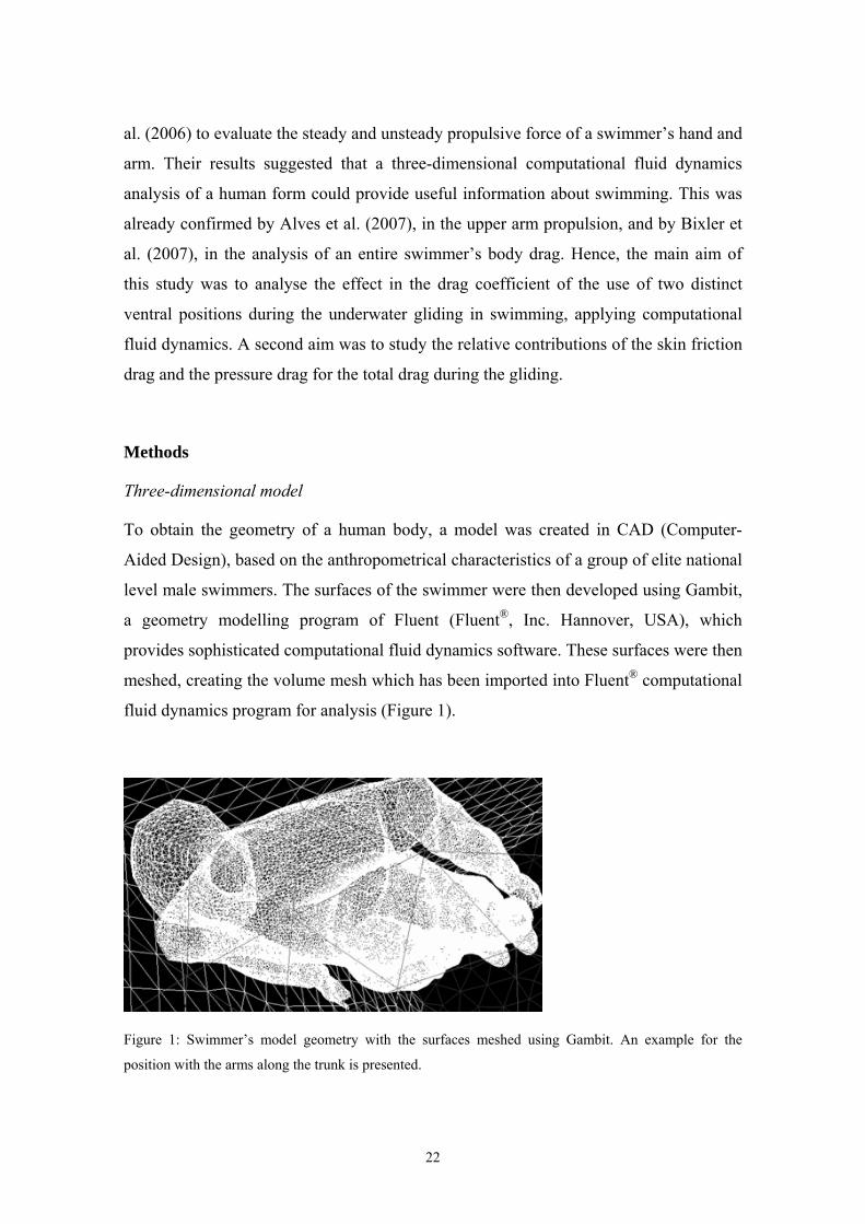
fluid dynamics program for analysis (Figure 1).
Figure 1: Swimmer’s model geometry with the surfaces meshed using Gambit. An example for the
position with the arms along the trunk is presented.
22
Computational fluid dynamics model
The swimmer was modelled as if he were gliding underwater in one of two distinct
ventral positions. The first position was a streamlined position, with the arms extended
at the front. This is the shape usually adopted after the start and after pushing off from
the wall after a turn. The second position was with the arms along the trunk. This is the
shape adopted by the swimmers during the second gliding phase after a turn in
breaststroke.
The computational fluid dynamics analyses were performed with the body in a
horizontal position with an attack angle of 0º. The attack angle was defined as the angle
between a horizontal line and a line drawn from the vertex to the ankle bone.
The swimmer’s model used for the analysis was 1.87 m tall with head, chest, waist and
hip circumferences of 0.57 m, 1.04 m, 0.85 m and 0.95 m, respectively. In the
streamlined position, the model had a finger to toe length of 2.37 m and in the position
with the arms along the trunk the distance from vertex to toe was 1.92 m.
The boundary conditions of the computational fluid dynamics model were designed to
represent the geometry and flow conditions of a part of a lane in a swimming pool. The
water depth of the model was 1.80 m with a 2.50 m width. The length was 8.0 m in the
streamlined position and 7.55 m in the position with the arms along the trunk, allowing
in both situations the same flow conditions behind and in front of the swimmer. In both
positions, the distance to the front surface was 2.0 m and to the back surface was 3.63
m. The swimmer model middle line was placed at a water depth of 0.90 m, equidistant
from the top and bottom surfaces (Figure 2).
The model’s body surface had roughness parameters of zero. The whole domain was
meshed with 900 million cells. The grid was a hybrid mesh composed of prisms and
pyramids. Significant efforts were conducted to ensure that the model would provide
accurate results, namely by decreasing the grid node separation in areas of high velocity
and pressure gradients.
23
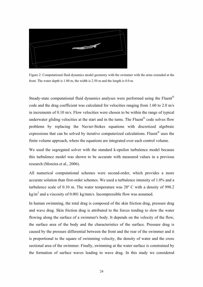
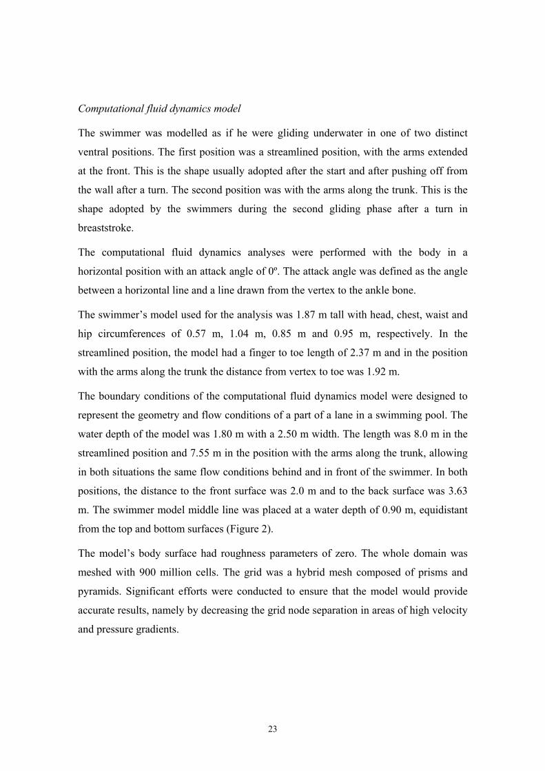
Figure 2: Computational fluid dynamics model geometry with the swimmer with the arms extended at the
front. The water depth is 1.80 m, the width is 2.50 m and the length is 8.0 m.
Steady-state computational fluid dynamics analyses were performed using the Fluent®
code and the drag coefficient was calculated for velocities ranging from 1.60 to 2.0 m/s
in increments of 0.10 m/s. Flow velocities were chosen to be within the range of typical
underwater gliding velocities at the start and in the turns. The Fluent® code solves flow
problems by replacing the Navier-Stokes equations with discretized algebraic
expressions that can be solved by iterative computerized calculations. Fluent® uses the
finite volume approach, where the equations are integrated over each control volume.
We used the segregated solver with the standard k-epsilon turbulence model because
this turbulence model was shown to be accurate with measured values in a previous
research (Moreira et al., 2006).
All numerical computational schemes were second-order, which provides a more
accurate solution than first-order schemes. We used a turbulence intensity of 1.0% and a
turbulence scale of 0.10 m. The water temperature was 28º C with a density of 998.2
kg/m3 and a viscosity of 0.001 kg/mm/s. Incompressible flow was assumed.
In human swimming, the total drag is composed of the skin friction drag, pressure drag
and wave drag. Skin friction drag is attributed to the forces tending to slow the water
flowing along the surface of a swimmer's body. It depends on the velocity of the flow,
the surface area of the body and the characteristics of the surface. Pressure drag is
caused by the pressure differential between the front and the rear of the swimmer and it
is proportional to the square of swimming velocity, the density of water and the cross
sectional area of the swimmer. Finally, swimming at the water surface is constrained by
the formation of surface waves leading to wave drag. In this study we considered
24
hydrodynamic drag depending only on the skin friction and pressure drag since the
model was placed 0.90 m underwater. These two drag components were computed by
Fluent® software.
Statistical analyses
To analyse the relationship between the velocity and the drag coefficient, regression
lines between these parameters were computed. The regression equations were
calculated and the R2 value was used as a measure of the robustness of the model.
Results
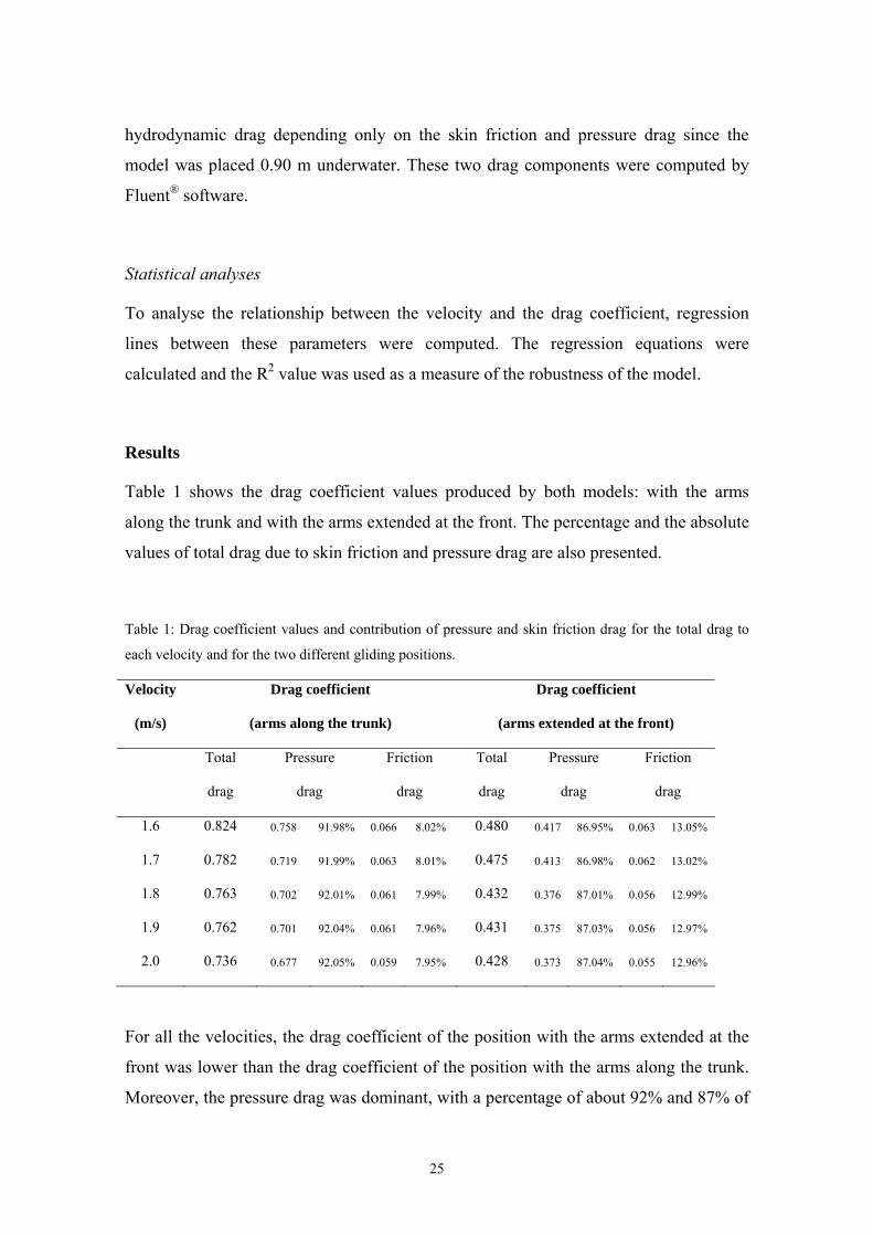
Table 1 shows the drag coefficient values produced by both models: with the arms
along the trunk and with the arms extended at the front. The percentage and the absolute
values of total drag due to skin friction and pressure drag are also presented.
Table 1: Drag coefficient values and contribution of pressure and skin friction drag for the total drag to
each velocity and for the two different gliding positions.
Velocity Drag coefficient Drag coefficient
(m/s) (arms along the trunk) (arms extended at the front)
Total
drag
Pressure
drag
Friction
drag
Total
drag
Pressure
drag
Friction
drag
1.6 0.824 0.758 91.98% 0.066 8.02% 0.480 0.417 86.95% 0.063 13.05%
1.7 0.782 0.719 91.99% 0.063 8.01% 0.475 0.413 86.98% 0.062 13.02%
1.8 0.763 0.702 92.01% 0.061 7.99% 0.432 0.376 87.01% 0.056 12.99%
1.9 0.762 0.701 92.04% 0.061 7.96% 0.431 0.375 87.03% 0.056 12.97%
2.0 0.736 0.677 92.05% 0.059 7.95% 0.428 0.373 87.04% 0.055 12.96%
For all the velocities, the drag coefficient of the position with the arms extended at the
front was lower than the drag coefficient of the position with the arms along the trunk.
Moreover, the pressure drag was dominant, with a percentage of about 92% and 87% of
25
the total drag, in the position with the arms along the trunk and with the arms extended
at the front, respectively. The absolute values of skin friction drag were quite similar in
both positions.
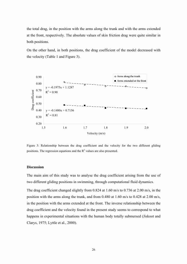
On the other hand, in both positions, the drag coefficient of the model decreased with
the velocity (Table 1 and Figure 3).
Arms along the trunk0,90
y = -0,1975x + 1,1287R2 = 0,90
y = -0,148x + 0,7156R2 = 0,81
Veloci .s-1)
0,20
0,30
0,40
0,50
0,60
0,70
0,80
0.90 Arms extended at the front
0.80 y = -0.1975x + 1.1287
0.70
Dra
g co
effic
ient
R2 = 0.90 0.60
0.50
0.40 y = -0.1480 156 x + 0.7R2 = 0.81 0.30
0.20 1,50 1,60 1,70 1,80 1,90 2,00 1.5 1.6 1.7 1.8 1.9 2.0
ty (mVelocity (m/s)
Figure 3: Relationship between the drag coefficient and the velocity for the two different gliding
positions. The regression equations and the R2 values are also presented.
Discussion
The main aim of this study was to analyse the drag coefficient arising from the use of
two different gliding positions in swimming, through computational fluid dynamics.
The drag coefficient changed slightly from 0.824 at 1.60 m/s to 0.736 at 2.00 m/s, in the
position with the arms along the trunk, and from 0.480 at 1.60 m/s to 0.428 at 2.00 m/s,
in the position with the arms extended at the front. The inverse relationship between the
drag coefficient and the velocity found in the present study seems to correspond to what
happens in experimental situations with the human body totally submersed (Jiskoot and
Clarys, 1975; Lyttle et al., 2000).
26
Moreover, the gliding position with the arms extended at the front presented lower drag
coefficient values than the position with the arms placed along the trunk. This body
position, with the arms at the front, is mostly accepted by the swimming technical and
scientific communities as the most hydrodynamic one, being called the streamlined
position (Guimarães and Hay, 1985). The position with the arms extended at the front
seems to be the one that allows a higher reduction of the negative hydrodynamic effects
of the human body morphology: a body with various pressure points due to the large
changes in its shape. This position seems to smooth the anatomical shape especially at
the head and shoulders. Considering the breaststroke turn, the first gliding, performed
with the arms at the front, must be emphasized in relation to the second gliding,
performed with the arms along the trunk.
Bixler et al. (2007) demonstrated the validity of computational fluid dynamics analysis
as a tool to examine the water flow around a submerged swimmer’s body. This form of
research has opened a new gate of analysis into the swimming hydrodynamics and has
been shown to hold promise as a way to assess the flow characteristics and associated
drag forces experienced by swimmers, for instance, in different gliding positions after
starts and turns.
Another aim of the present study was to analyze the influence of the skin friction drag
and the pressure drag in the total drag during the gliding. We choose a pool depth of
1.80 m, with the swimmer model placed at the midpoint between top and bottom, to
avoid significant wave drag, limiting our research to the influence of the pressure drag
and the skin friction drag in the total drag coefficient. Lyttle et al. (1999) concluded that
there is no significant wave drag when a typical adult swimmer is at least 0.6 m under
the water’s surface.
The computed drag forces components showed that for both gliding positions the
pressure drag was dominant. Nevertheless, skin friction drag was by no means
negligible, presenting an absolute value of about 0.06. This drag component represented
≈13% and ≈8% of total drag in the position with the arms extended at the front and with
the arms along the trunk, respectively. However, these values are based on the swimmer
model’s surface having a zero roughness. Therefore, the development of roughness
parameters for human skin would allow a more accurate computational fluid dynamics
27
model to be built in further studies. Since this task is still in development, we assumed
to conduct our simulations based upon the swimmer’s surface having a zero roughness.
We chose this value as a first step in the application of numerical simulation techniques
in swimming research, using a three-dimensional model of a whole human body. We
had to opt between a certain value and a zero value. Indeed, we simulated a situation as
the swimmer was shaved (smoothed), with roughness zero. In our opinion, the change
in the roughness parameter would affect each body position in approximately the same
way and our main finding would be the same. However, the contribution of each drag
component would possibly be a little different with the use of a roughness skin value.
Nevertheless, we are convinced that the pressure drag would be dominant and the skin
friction drag would be important as well. How this relative contribution would be
changed is a very interesting question, which could lead to further research. But one can
speculate about this. On one hand, if the surface roughness were increased in the model,
the skin friction drag would probably be higher. It is expected that the surface roughness
increase could lead to increase the turbulence around the surface, thus increasing skin
friction drag. On the other hand, if the surface roughness were increased the pressure
drag could be reduced. The boundary layer, which would be mainly laminar, would
change into a turbulent one (Massey, 1989). When the flow regime is laminar,
separation at the body surface starts almost as soon as the pressure gradient becomes
adverse and a larger wake forms while when the flow regime is turbulent, separation is
delayed and the corresponding wake is smaller, thus decreasing pressure drag. The
importance of keeping the boundary layer attached to the swimmer body surface is so
important that swimwear manufacturers sometimes purposely cause the boundary layer
to become turbulent (Polidori et al., 2006).
Moreover, since the absolute values of skin friction drag are about the same in the two
gliding positions, it is possible that the increase in this component would be
approximately the same. The main difference could occur at the pressure drag since the
position with the arms along the trunk presented higher absolute values. It is expected
that the drag force decrease in this body position would be more accentuated, thus
decreasing the differences between the two models. However, we think these changes
would not be sufficient to have an effect on our primary finding: the gliding position
28
with the arms extended at the front produced lower drag coefficients than with the arms
placed along the trunk.
Another different situation could happen if the swimmer were at the water’s surface.
The contribution of the skin friction drag would be reduced due to the reduction in the
wetted area and the generation of wave drag (Bixler et al., 2007).
Although limited to passive drag, this study allowed the evaluation of the effects of
different body positions on performance, being a first step towards the analysis of active
drag. On the other hand, computational fluid dynamics methods have provided a way to
estimate the relative contribution of each drag component to the total drag. Future
studies could improve this computational fluid dynamics results by analysing the
passive drag of a swimmer at the water’s surface and including wave drag in the
measurements. Moreover, the evaluation of the active drag while the swimmer is
kicking must also be attempted in the future.
References
Alves, F., Marinho, D., Leal, L., Rouboa, A., Silva, A. (2007). 3-D computational fluid dynamics of the
hand and forearm in swimming. Medicine and Science in Sports and Exercise, 39(Suppl. 1), S9.
Bixler, B.S., Schloder, M. (1996). Computational fluid dynamics: an analytical tool for the 21st century
swimming scientist. Journal of Swimming Research, 11, 4-22.
Bixler, B., Pease, D., Fairhurst, F. (2007). The accuracy of computational fluid dynamics analysis of the
passive drag of a male swimmer. Sports Biomechanics, 6, 81-98.
Cossor, J., Mason, B. (2001). Swim start performances at the Sydney 2000 Olympic Games. In: J.
Blackwell, R. Sanders (Eds.), Proceedings of Swim Sessions of the XIX Symposium on
Biomechanics in Sports, pp. 70-74. San Francisco: University of San Francisco.
Guimarães, A., Hay, J. (1985). A mechanical analysis of the grab starting technique in swimming.
International Journal of Sports Biomechanics, 1, 25-35.
Jiskoot, J., Clarys, J.P. (1975). Body resistance on and under the water surface. In: L. Lewillie, J.P. Clarys
(Eds.), Swimming II, pp. 105-109. Baltimore: University Park Press.
Lyttle, A.D., Blanksby, B.A., Elliott, B.C., Lloyd, D.G. (1999). Optimal depth for streamlined gliding. In:
K.L. Keskinen, P.V. Komi, A.P. Hollander (Eds.), Biomechanics and Medicine in Swimming VIII,
pp. 165-170. Jyvaskyla: Gummerus Printing.
29
Lyttle, A., Blanksby, B., Elliot, B., Lloyd, D. (2000). Net forces during tethered simulation of underwater
streamlined gliding and kicking technique of the freestyle turn. Journal of Sports Sciences, 18,
801-807.
Massey, B.S. (1989). Mechanics of Fluids. London: Chapman & Hall.
Moreira, A., Rouboa, A., Silva, A., Sousa, L., Marinho, D., Alves, F., Reis, V., Vilas-Boas, J.P., Carneiro,
A., Machado, L. (2006). Computational analysis of the turbulent flow around a cylinder.
Portuguese Journal of Sport Sciences, 6(Suppl. 1), 105.
Polidori, G., Taiar, R., Fohanno, S., Mai, T.H., Lodini, A. (2006). Skin-friction drag analysis from the
forced convection modeling in simplified underwater swimming. Journal of Biomechanics, 39,
2535-2541.
Rouboa, A., Silva, A., Leal, L., Rocha, J., Alves, F. (2006). The effect of swimmer’s hand/forearm
acceleration on propulsive forces generation using computational fluid dynamics. Journal of
Biomechanics, 39, 1239-1248.
Vilas-Boas, J.P., Cruz, M.J., Sousa, F., Conceição, F., Carvalho, J.M. (2000). Integrated kinematic and
dynamic analysis of two track-start techniques. In: R. Sanders, Y. Hong (Eds.), Proceedings of the
XVIII International Symposium on Biomechanics in Sports, Applied Program – Application of
Biomechanical Study in Swimming, pp. 113-117. Hong Kong: The Chinese University Press.
30
Study 2
The use of Computational Fluid Dynamics in swimming research
Marinho, D.A., Reis, V.M., Alves, F.B., Vilas-Boas, J.P., Machado, L., Rouboa, A.I., Silva, A.J. (2008).
The use of Computational Fluid Dynamics in swimming research. International Journal for
Computational Vision and Biomechanics (in press).
31
The use of Computational Fluid Dynamics in swimming research
Abstract
The aim of the present study was to apply Computational Fluid Dynamics to the study of the
hand/forearm forces in swimming using a three-dimensional model. Models used in the simulations were
created in CAD, based on real dimensions of a right adult human hand/forearm. The governing system of
equations considered was the incompressible Reynolds averaged Navier-Stokes equations implemented in
the Fluent® commercial code. The drag coefficient was the main responsible for propulsion, with a
maximum value of force propulsion corresponding to a pitch angle of 90º. The lift coefficient seemed to
play a less important role in the generation of propulsive force with pitch angles of 0º and 90º but it is
important with pitch angles of 30º, 45º and 60º.
Introduction
The creation of propulsive force in human swimming has been recently studied using
numerical simulation techniques with computational fluid dynamics (CFD) models
(Bixler and Schloder, 1996; Bixler and Riewald, 2002; Silva et al., 2005; Rouboa et al.,
2006; Gardano and Dabnichki, 2006).
Nevertheless, some limitations still persist, regarding the geometrical representation of
the human limbs. In the pioneer study of Bixler and Schloder (1996), these authors used
a disc with a similar area of a swimmer hand, while Gardano and Dabnichki (2006)
used standard geometric solids to represent the superior limb. Rouboa et al. (2006) tried
to correct and to complement the backward works using a two-dimensional (2-D) model
of a hand and a forearm of a swimmer, situation that seems to be an important step
forward in the application of CFD to the human propulsion. However, it seems it is
possible to go forward, reason why we propose to apply CFD to the studied of the hand
and forearm propulsion with three-dimensional (3-D) models, as it was already
experimented by Lyttle and Keys (2006) to analyse the dolphin kicking propulsion.
In this sense, with this work we want to continue using CFD as a new technology in the
swimming research, applying CFD to the 3-D study of the propulsion produced by the
swimmer hand and forearm. Therefore, the aim of the present study is twofold. First,
continuing to disseminate the use of CFD as a new tool in swimming research. Second,
32
to apply the method in the determination of the relative contribution of drag and lift
coefficients resulting from the numerical resolution equations of the flow around the
swimmers hand and forearm using 3-D models under the steady flow conditions.
Methods
Mathematical model
The dynamic fluid forces produced by the hand/forearm, drag (D) and lift (L), were
measured in this study. These forces are function of the fluid velocity and they were
measured by the application of the equations 1 and 2.
D = CD ½ ρ A V2 (1)
L = CL ½ ρ A V2 (2)
In equations 1 and 2, V is the fluid velocity, CD and CL are the drag and lift coefficients,
respectively, ρ is the fluid density and A is the projection area of the model for different
angles of pitch used in this study (0º, 30º, 45º, 60º, 90º).
CFD methodology consists of a mathematical model applied to the fluid flow in a given
domain that replaces the Navier-Stokes equations with discretized algebraic expressions
that can be solved by iterative computerized calculations. This domain consists of a
three-dimensional grid or mesh of cells that simulate the fluid flow (Figure 1). The fluid
mechanical properties, the flow characteristics along the outside grid boundaries and the
mathematical relationship to account the turbulence were considered.
We used the segregated solver with the standard k-epsilon turbulence model because
this turbulence model was shown to be accurate with measured values in a previous
research (Moreira et al., 2006).
33
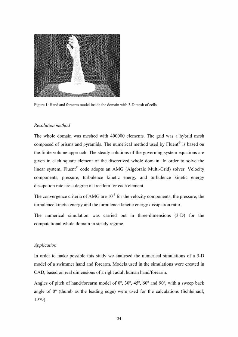
Figure 1: Hand and forearm model inside the domain with 3-D mesh of cells.
Resolution method
The whole domain was meshed with 400000 elements. The grid was a hybrid mesh
composed of prisms and pyramids. The numerical method used by Fluent® is based on
the finite volume approach. The steady solutions of the governing system equations are
given in each square element of the discretized whole domain. In order to solve the
linear system, Fluent® code adopts an AMG (Algebraic Multi-Grid) solver. Velocity
components, pressure, turbulence kinetic energy and turbulence kinetic energy
dissipation rate are a degree of freedom for each element.
The convergence criteria of AMG are 10-3 for the velocity components, the pressure, the
turbulence kinetic energy and the turbulence kinetic energy dissipation ratio.
The numerical simulation was carried out in three-dimensions (3-D) for the
computational whole domain in steady regime.
Application
In order to make possible this study we analysed the numerical simulations of a 3-D
model of a swimmer hand and forearm. Models used in the simulations were created in
CAD, based on real dimensions of a right adult human hand/forearm.
Angles of pitch of hand/forearm model of 0º, 30º, 45º, 60º and 90º, with a sweep back
angle of 0º (thumb as the leading edge) were used for the calculations (Schleihauf,
1979).
34
On the left side of the domain access (figure 1), the x component of the velocity was
chosen to be within or near the range of typical hand velocities during freestyle
swimming underwater path: from 0.5 m/s to 4 m/s, with 0.5 m/s increments. The y and z
components of the velocity were assumed to be equal to zero. On the right side, the
pressure was equal to 1 atm, fundamental pre requisite for not allowing the reflection of
the flow.
Around the model, the three components of the velocity were considered as equal to
zero. This allows the adhesion of the fluid to the model.
It was also considered the action of the gravity force (g = 9.81 m/s2), as well as the
turbulence percentage of 1% with 0.1 m of length.
The considered fluid was water, incompressible with density (ρ = 996.6 x 10⁻⁹ kg/mm3)
and viscosity (μ = 8.571 x 10⁻⁷ kg/mm/s).
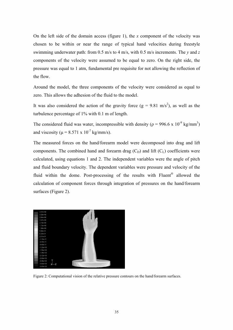
The measured forces on the hand/forearm model were decomposed into drag and lift
components. The combined hand and forearm drag (CD) and lift (CL) coefficients were
calculated, using equations 1 and 2. The independent variables were the angle of pitch
and fluid boundary velocity. The dependent variables were pressure and velocity of the
fluid within the dome. Post-processing of the results with Fluent® allowed the
calculation of component forces through integration of pressures on the hand/forearm
surfaces (Figure 2).
Figure 2: Computational vision of the relative pressure contours on the hand/forearm surfaces.
35
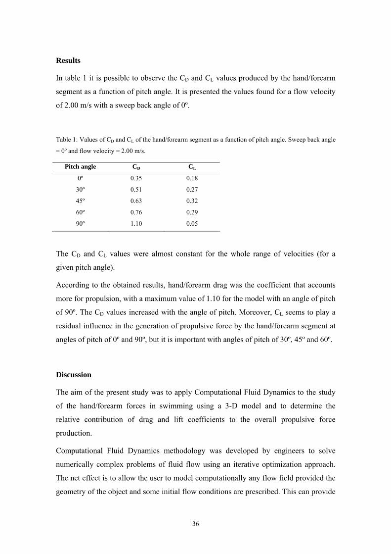
Results
In table 1 it is possible to observe the CD and CL values produced by the hand/forearm
segment as a function of pitch angle. It is presented the values found for a flow velocity
of 2.00 m/s with a sweep back angle of 0º.
Table 1: Values of CD and CL of the hand/forearm segment as a function of pitch angle. Sweep back angle
= 0º and flow velocity = 2.00 m/s.
Pitch angle CD CL
0º 0.35 0.18
30º 0.51 0.27
45º 0.63 0.32
60º 0.76 0.29
90º 1.10 0.05
The CD and CL values were almost constant for the whole range of velocities (for a
given pitch angle).
According to the obtained results, hand/forearm drag was the coefficient that accounts
more for propulsion, with a maximum value of 1.10 for the model with an angle of pitch
of 90º. The CD values increased with the angle of pitch. Moreover, CL seems to play a
residual influence in the generation of propulsive force by the hand/forearm segment at
angles of pitch of 0º and 90º, but it is important with angles of pitch of 30º, 45º and 60º.
Discussion
The aim of the present study was to apply Computational Fluid Dynamics to the study
of the hand/forearm forces in swimming using a 3-D model and to determine the
relative contribution of drag and lift coefficients to the overall propulsive force
production.
Computational Fluid Dynamics methodology was developed by engineers to solve
numerically complex problems of fluid flow using an iterative optimization approach.
The net effect is to allow the user to model computationally any flow field provided the
geometry of the object and some initial flow conditions are prescribed. This can provide
36
answers to problems which have been unobtainable using physical testing methods,
thereby bridging the gap between theoretical and experimental fluid dynamics. In this
research we tried to improve the previous studies that applied CFD to the analysis of
swimming propulsion, using a more realistic model of the swimmer hand and forearm
(3-D model). Thought, this model still needs to be improved, namely using a model in
which the fingers would be extended. This is an issue that should be addressed in future
studies.
We are very pleased with the results pointed out in the simulations of our study. CD was
the main responsible for propulsion, with the maximum value of force production
corresponding to an angle of pitch of 90º, as expected. The CD obtained the highest
value at an orientation of the hand/forearm plane where the model was directly
perpendicular to the direction of the flow. The same result was reported by Berger et al.
(1995), in which the drag force increases to a maximum where the plane was the same
as the presented in this work (angle of pitch = 90º).
CL has a residual influence in the generation of propulsive force by the hand/forearm
segment for angles of pitch of 0º and 90º, but it is important with angles of pitch of 30º,
45º and 60º. These data confirm recent studies reporting reduced contribution of lift
component to the overall propulsive force generation by the hand/forearm segment in
front crawl swimming, except for the insweep phase, when the angle of attack is within
30º-60º (Berger et al., 1995; Sanders, 1999; Bixler and Riewald, 2002; Rouboa et al.,
2006).
Although in this study we had only tested flow in steady regime and this situation does
not truly represent what happens during swimming, the present study allowed us to
apply CFD in the study of propulsive forces in swimming, using a three-dimensional
model of a human hand/forearm. By itself, this situation seems to be an important step
to the advancement of this technology in sports scope.
The results of the values of CD and CL are similar to the ones found in experimental
studies (Wood, 1977; Schleihauf, 1979; Berger et al., 1995; Sanders, 1999), important
fact to the methodological validation of CFD, giving as well conditions to the primary
acceptation to the analysis of hydrodynamic forces produced through unsteady flow
conditions and through different orientations of the propelling segments.
37
For the three different orientation models and for the whole studied velocity range, the
CD and CL remain constant. Similar results were observed as well in other studies using
CFD (Bixler and Riewald, 2002; Silva et al., 2005; Rouboa et al., 2006).
Conclusion
This study tried to apply CFD to the analysis of swimming propulsion. As conclusions
we can state that the computational data found seem to demonstrate an important role of
the drag force and a minor contribution of the lift force to the propulsive force
production by the swimmer hand/forearm segment.
On the other hand, it was demonstrated the utility of using CFD in the propulsive force
measurements, using a more realistic model (3-D) of a human segment. This situation is
an additional step forward to the necessary continuation to keep developing this
technology in sport studies, in general, and in swimming, as a particular case.
References
Berger, M.A., de Groot, G., Hollander, AP. (1995). Hydrodynamic drag and lift forces on human hand
arm models. Journal of Biomechanics, 28, 125-133.
Bixler, B.S., Schloder, M. (1996). Computational fluid dynamics: an analytical tool for the 21st century
swimming scientist. Journal of Swimming Research, 11, 4-22.
Bixler, B.S., Riewald, S. (2002). Analysis of swimmer’s hand and arm in steady flow conditions using
computational fluid dynamics. Journal of Biomechanics, 35, 713-717.
Gardano, P., Dabnichki, P. (2006). On hydrodynamics of drag and lift of the human arm. Journal of
Biomechanics, 39, 2767-2773.
Lyttle, A., Keys, M. (2006). The application of computational fluid dynamics for technique prescription
in underwater kicking. Portuguese Journal of Sport Sciences, 6(Suppl. 2), 233-235.
Moreira, A., Rouboa, A., Silva, A.J., Sousa, L., Marinho, D., Alves, F., Reis, V., Vilas-Boas, J.P.,
Carneiro, A., Machado, L. (2006). Computational analysis of the turbulent flow around a cylinder.
Portuguese Journal of Sport Sciences, 6(Suppl. 1), 105.
Rouboa, A, Silva, A., Leal, L., Rocha, J., Alves, F. (2006). The effect of swimmer’s hand/forearm
acceleration on propulsive forces generation using computational fluid dynamics. Journal of
Biomechanics, 39, 1239-1248.
38
Sanders, R.H. (1999). Hydrodynamic characteristics of a swimmer’s hand. Journal of Applied
Biomechanics, 15, 3-26.
Schleihauf, R.E. (1979). A hydrodynamic analysis of swimming propulsion. In: J. Terauds, E.W.
Bedingfield (Eds), Swimming III, pp. 70-109. Baltimore: University Park Press.
Silva, A., Rouboa, A., Leal, L., Rocha, J., Alves, F., Moreira, A., Reis, V., Vilas-Boas, J.P. (2005).
Measurement of swimmer's hand/forearm propulsive forces generation using computational fluid
dynamics. Portuguese Journal of Sport Sciences, 5, 288-297.
Wood, T.C. (1977). A fluid dynamic analysis of the propulsive potential of the hand and forearm in
swimming. Master of Science Thesis. Halifax, NS: Dalhouise University Press.
39
Study 3
Design of a three-dimensional hand/forearm model to apply
Computational Fluid Dynamics
Marinho, D.A., Reis, V.M., Vilas-Boas, J.P., Alves, F.B., Machado, L., Rouboa, A.I. and Silva, A.J.
(2008). Design of a three-dimensional hand/forearm model to apply Computational Fluid Dynamics.
Brazilian Archives of Biology and Technology (in press).
40
Design of a three-dimensional hand/forearm model to apply
Computational Fluid Dynamics
Abstract
The purpose of this study was to develop a three-dimensional digital model of a human hand and forearm
to apply Computational Fluid Dynamics to propulsion analysis in swimming. Computer tomography
scans of the hand and forearm of an Olympic swimmer were applied. The data were converted, using
image processing techniques, into relevant coordinate input, which can be used in Computational Fluid
Dynamics software. From that analysis it was possible to verify an almost perfect agreement between the
true human segment and the digital model. This technique can be used as a means to overcome the
difficulties in developing a true three-dimensional model of a specific segment of the human body.
Additionally, it may be used to improve the use of Computational Fluid Dynamics generally in sports and
specifically in swimming studies, decreasing the gap between the experimental and the computational
data.
Introduction
The finite element method is currently one of the best established numerical tools in the
field of biomechanical engineering and has been used in the computational analysis of
the fluid flow around human structures. In the sports scope, it has been used in the study
of the propulsive forces produced by the hand and forearm in human swimming.
Despite the increasing amount of high quality research, a common weakness still
remains. Practically all the models have been developed based on approximate
analytical representations of the human structures and their geometrical accuracy has
never been discussed. This approach has been commonly adopted, for example, to
reduce the computational cost of memory requirements (Aritan et al., 1997). However,
one of the main reasons for such limitations is the difficulty to design a true digital
model of the human limbs.
In most cases, the authors used two-dimensional models (Bixler and Schloder, 1996;
Silva et al., 2005; Rouboa et al., 2006) and when three-dimensional models were used,
these were very simple and reductive representations of the human limbs (Gardano and
Dabnichki, 2006). These differences between true and computed models could lead to
less accurate numerical results (Candalai and Reddy, 1992). In an experimental
41
simulation of the effect of the ischial tuberosity’s geometry on the shear and
compressive stress in buttock tissue, Candalai and Reddy (1992) showed that the
influence of the geometry on the stress magnitude could be significant. In a numerical
simulation of this experimental work, a possible variation of more than 60% was found
in the shear stress.
Magnetic resonance imaging and computer tomography scans seem to be a good
approach for designing true human models. However, the use of these kinds of scans is
not a straightforward task and requires the implementation of image processing and
other numerical techniques, such as the conversion into relevant coordinate input. It
should be noted that mesh generation, the first step in finite element modeling, is a
tough procedure, especially when solving three-dimensional problems (Aritan et al.,
1997). Ideally, a mesh should allow modifications, usually by changing some
predefined parameters and it should be based on directly obtained anatomical data.
Thus, it is important to use the magnetic resonance imaging or the computer
tomography data to provide geometrical input for generation or modification of finite
element models. Most of the well established finite element software packages provide
special tools for parametric modification of an existing mesh. These tools help the user
to reduce the time and to increase the accuracy and reliability of model modifications.
Therefore, the aim of the present study was to develop a true three-dimensional model
of the human hand and forearm, through the transformation of computer tomography
scans into input data to apply Computational Fluid Dynamics to the propulsion analysis
in swimming.
Materials and Methods
Computational Fluid Dynamics
Computational Fluid Dynamics methodology consists of a mathematical model applied
to the fluid flow in a given domain. This domain replaces the Navier-Stokes equations
with discretized algebraic expressions that can be solved by iterative calculations. This
domain consists of a three-dimensional grid or mesh of cells that simulates the fluid
flow around structures. The fluid mechanical properties, the flow characteristics along
42
the outside grid boundaries and the mathematical relationship to account the turbulence
were also considered:
0divV = (1)
( ) 0VVkcvpV.VtV t
2
=∇+∇⎟⎟⎠
⎞⎜⎜⎝
⎛ε
+∇±∇+∇±∂∂
μ
(2)
ρε
kkkkkkk kkk −+
∂
⎟⎟⎠
⎞⎜⎜⎝
⎛∂∂
∂+
∂
⎟⎟⎠
⎞⎜⎜⎝
⎛∂∂
∂+
∂
⎟⎟⎠
⎞⎜⎜⎝
⎛∂∂
∂=
∂∂
+∂
∂+
∂∂
+∂
∂ Φμz
zσμ
yyσ
μ
xxσ
μ
z)V(
y)V(
x)V(
t)(
t
ttt
zyx ρρρρ
(3)
k
ρε
k
ε
εεε
ερVερVερVρk εεε2
t
ttt
zyx
zz
yy
xx
z)(
y)(
x)(
t)(
2CΦ−μ+∂
⎟⎟⎠
⎞⎜⎜⎝
⎛∂∂
σμ
∂
+∂
⎟⎟⎠
⎞⎜⎜⎝
⎛∂∂
σμ
∂
+∂
⎟⎟⎠
⎞⎜⎜⎝
⎛∂∂
σμ
∂
=∂
∂+
∂
∂+
∂∂
+∂
∂
(4)
Where k is the turbulent kinetic energy and ε is the turbulent kinetic energy dissipation
ratio. Vx, Vy and Vz represent the x, y and z components of the velocity V. μt is the
turbulent viscosity and ρ represents the fluid density. υ is the kinematic viscosity, Ф is
the pressure strain, C2, Cμ, σε and σk are model constants, 1.92, 0.09, 1.30 and 1.00,
respectively.
In order to create the three-dimensional digital model we applied computer tomography
scans of a hand and forearm segments of an Olympic swimmer. With these data we
converted the values into a format that can be read in Gambit, Fluent® pre-processor.
Fluent® software is used to simulate the fluid flow around structures, allowing the
analysis of values of pressure and speed around (i.e. the hand and forearm of a
swimmer). With these values we can calculate force components through integration of
pressures on the hand/forearm surfaces, using a realistic model of these human
segments, thus decreasing the gap between the experimental and the computational data.
The numerical method used by Fluent® is based on the finite volume approach. The
solutions of the governing system equations are given in each square element of the
discretized whole domain. In order to solve the linear system, Fluent® code adopts an
Algebraic Multi-Grid (AMG) solver. Velocity components, pressure, turbulent kinetic
43
energy and turbulent kinetic energy dissipation ratio are degrees of freedom (DOF) for
each element.
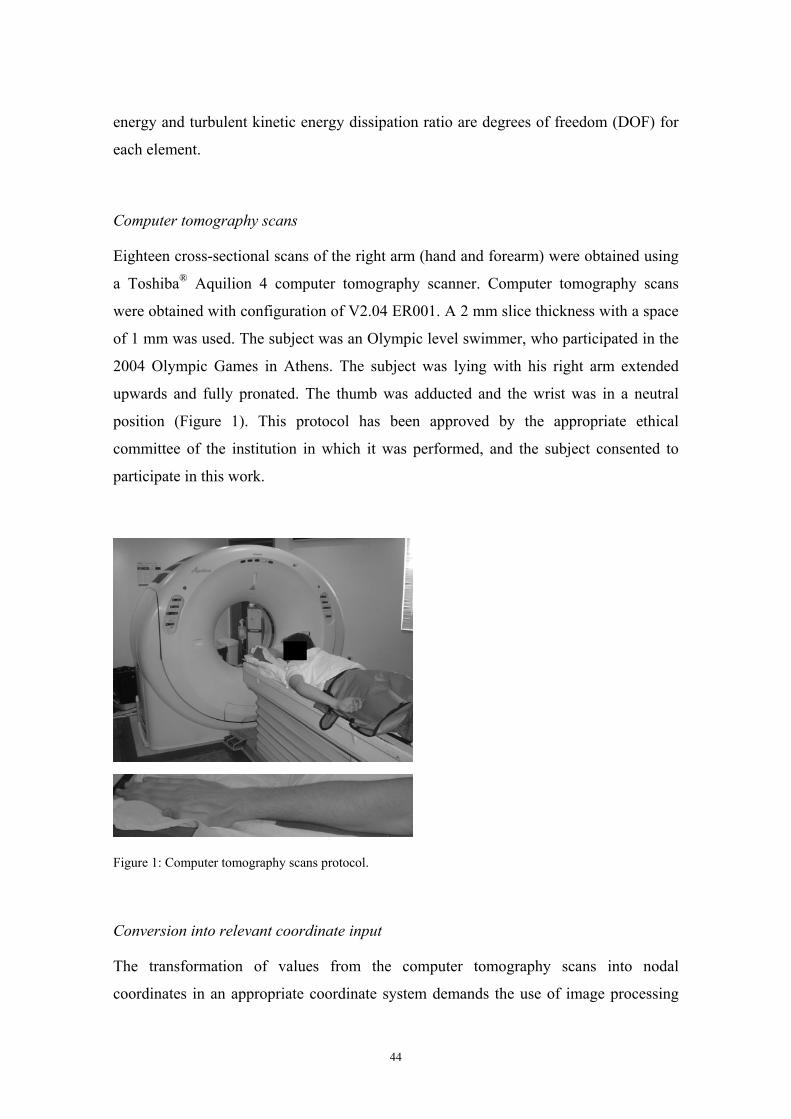
Computer tomography scans
Eighteen cross-sectional scans of the right arm (hand and forearm) were obtained using
a Toshiba® Aquilion 4 computer tomography scanner. Computer tomography scans
were obtained with configuration of V2.04 ER001. A 2 mm slice thickness with a space
of 1 mm was used. The subject was an Olympic level swimmer, who participated in the
2004 Olympic Games in Athens. The subject was lying with his right arm extended
upwards and fully pronated. The thumb was adducted and the wrist was in a neutral
position (Figure 1). This protocol has been approved by the appropriate ethical
committee of the institution in which it was performed, and the subject consented to
participate in this work.
Figure 1: Computer tomography scans protocol.
Conversion into relevant coordinate input
The transformation of values from the computer tomography scans into nodal
coordinates in an appropriate coordinate system demands the use of image processing
44
techniques. The image processing program used in this study was the Anatomics Pro®.
This program allowed obtaining the boundaries of the human segments, creating a
three-dimensional reconstruction of the swimmer hand and forearm. This program uses
computational functions, graphics functions and mouse functions.
At first, before processing and converting procedures the data was prepared, namely by
observing the computer tomography data and erasing the non-relevant parts of the
anatomical model. For example, surfaces supporting the subject were also scanned,
reason why it had to be defined the relevant points and deleted the irrelevant ones. This
step was also conducted using the software FreeForm Sensable®. Finally, the data was
converted into an IGES format (*.igs), that could be read by Gambit/Fluent® to define
the finite elements approach through the three-dimensional surfaces.
Results and Discussion
In figure 2 it is possible to observe the hand and forearm model produced by the image
processing techniques. We can verify an almost perfect agreement with the true human
segment. This technique could lead to overcome the difficulty to develop a true three-
dimensional model of a specific segment of the human body.
Figure 2: Two different perspectives of the hand and forearm model produced by the image processing
techniques.
45
As it was referred, one of the main limitations of the application of numerical
techniques in swimming research is the quality of the models used to represent the
human limbs. Indeed, there are few studies applying this computational tool in the
analysis of human swimming propulsion and they used very simple representations of
the human body (Bixler and Schloder, 1996; Silva et al., 2005; Gardano and Dabnichki,
2006; Rouboa et al., 2006). Despite the important contributes of those studies, the
design and the use of a more realistic model is an essential feature to the development of
Computational Fluid Dynamics in swimming analysis (Gardano and Dabnichki, 2006).
The generation of a three-dimensional model from computer tomography scans of the
human limbs has been used in other fields, such as in biomedical and engineering
scopes (e.g. Tu et al., 1995; Aritan et al., 1997; Long et al., 1998). Prosthetic design and
analysis, for instance, require a correct description of the limb geometry, allowing the
output from the program to be used as a digital input for manufacturing prosthetics or
limb models. Moreover, the magnetic resonance imaging techniques could allow clear
separation of the skin, fat and muscle layers. Furthermore, the local compartment fat
content can be estimated with a high level of accuracy (Aritan et al., 1997). These
applications suggest that there is scope for some physiological applications such as
finding muscle cross-sections or volumes. However, in this study only the outer contour
of the hand and forearm were considered. The generation of the mesh of cells to define
the finite elements, allowing the analysis of the fluid flow takes place around those
segments. The mesh of the whole domain was defined in Gambit Module, a mesh tool
of the Fluent® software. The hand/forearm model was placed centred in the domain with
larger dimensions in order to determine the undisturbed boundary conditions. The
schematic design of the computational model is shown in figure 3. The whole domain
was meshed with a hybrid mesh composed of prisms and pyramids.
With this model it was possible to export the generated mesh to the Fluent® processor,
where we were able to define the conditions suitable to be computed. It was possible to
compute the force values produced by the hand and forearm model through the
integration of pressures on the hand/forearm surfaces (Figure 4). Fluent software allows
the analysis of the force components in the three directions of the space, with the model
with different orientations, as it occurs in swimming.
46
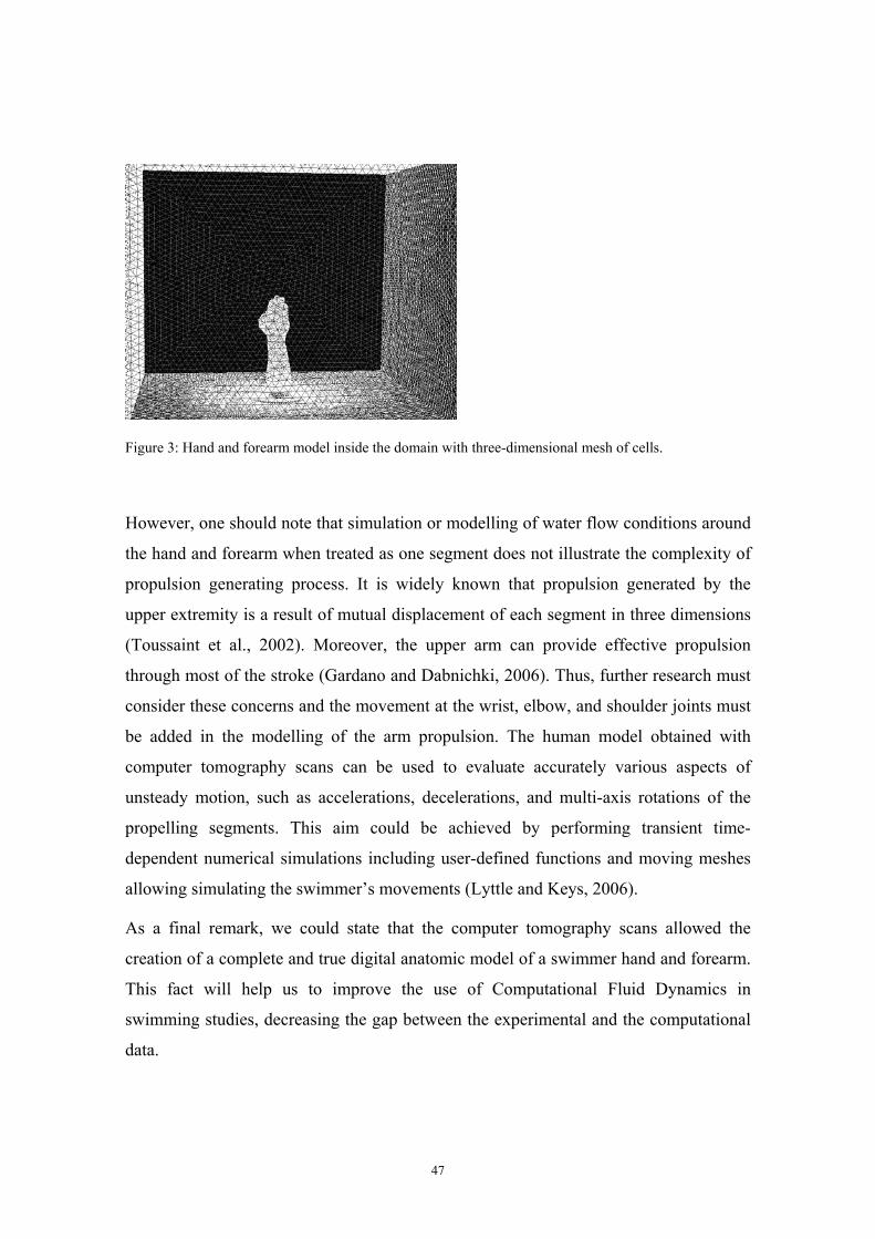
Figure 3: Hand and forearm model inside the domain with three-dimensional mesh of cells.
However, one should note that simulation or modelling of water flow conditions around
the hand and forearm when treated as one segment does not illustrate the complexity of
propulsion generating process. It is widely known that propulsion generated by the
upper extremity is a result of mutual displacement of each segment in three dimensions
(Toussaint et al., 2002). Moreover, the upper arm can provide effective propulsion
through most of the stroke (Gardano and Dabnichki, 2006). Thus, further research must
consider these concerns and the movement at the wrist, elbow, and shoulder joints must
be added in the modelling of the arm propulsion. The human model obtained with
computer tomography scans can be used to evaluate accurately various aspects of
unsteady motion, such as accelerations, decelerations, and multi-axis rotations of the
propelling segments. This aim could be achieved by performing transient time-
dependent numerical simulations including user-defined functions and moving meshes
allowing simulating the swimmer’s movements (Lyttle and Keys, 2006).
As a final remark, we could state that the computer tomography scans allowed the
creation of a complete and true digital anatomic model of a swimmer hand and forearm.
This fact will help us to improve the use of Computational Fluid Dynamics in
swimming studies, decreasing the gap between the experimental and the computational
data.
47
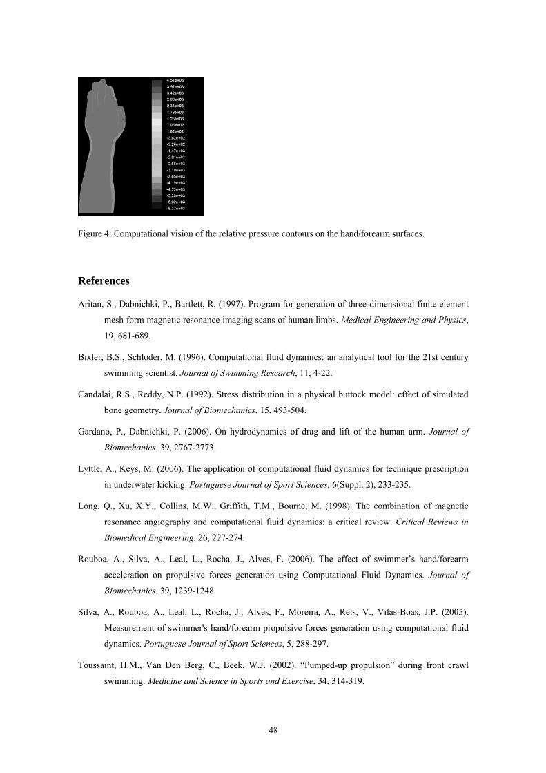
Figure 4: Computational vision of the relative pressure contours on the hand/forearm surfaces.
References
Aritan, S., Dabnichki, P., Bartlett, R. (1997). Program for generation of three-dimensional finite element
mesh form magnetic resonance imaging scans of human limbs. Medical Engineering and Physics,
19, 681-689.
Bixler, B.S., Schloder, M. (1996). Computational fluid dynamics: an analytical tool for the 21st century
swimming scientist. Journal of Swimming Research, 11, 4-22.
Candalai, R.S., Reddy, N.P. (1992). Stress distribution in a physical buttock model: effect of simulated
bone geometry. Journal of Biomechanics, 15, 493-504.
Gardano, P., Dabnichki, P. (2006). On hydrodynamics of drag and lift of the human arm. Journal of
Biomechanics, 39, 2767-2773.
Lyttle, A., Keys, M. (2006). The application of computational fluid dynamics for technique prescription
in underwater kicking. Portuguese Journal of Sport Sciences, 6(Suppl. 2), 233-235.
Long, Q., Xu, X.Y., Collins, M.W., Griffith, T.M., Bourne, M. (1998). The combination of magnetic
resonance angiography and computational fluid dynamics: a critical review. Critical Reviews in
Biomedical Engineering, 26, 227-274.
Rouboa, A., Silva, A., Leal, L., Rocha, J., Alves, F. (2006). The effect of swimmer’s hand/forearm
acceleration on propulsive forces generation using Computational Fluid Dynamics. Journal of
Biomechanics, 39, 1239-1248.
Silva, A., Rouboa, A., Leal, L., Rocha, J., Alves, F., Moreira, A., Reis, V., Vilas-Boas, J.P. (2005).
Measurement of swimmer's hand/forearm propulsive forces generation using computational fluid
dynamics. Portuguese Journal of Sport Sciences, 5, 288-297.
Toussaint, H.M., Van Den Berg, C., Beek, W.J. (2002). “Pumped-up propulsion” during front crawl
swimming. Medicine and Science in Sports and Exercise, 34, 314-319.
48
Tu, H.K., Matheny, A., Goldgof, D.B., Bunke, H. (1995). Left ventricular boundary detection from
spatio-temporal volumetric computer tomography images. Computerized Medical Imaging and
Graphics, 19, 27-46.
49
Study 4
Computational analysis of the hand and forearm propulsion in
swimming
Marinho, D.A., Vilas-Boas, J.P., Alves, F.B., Machado, L., Barbosa, T.M., Reis, V.M., Rouboa, A.I.,
Silva, A.J. (2008). Computational analysis of the hand and forearm propulsion in swimming.
International Journal of Sports Medicine (under revision).
50
Computational analysis of the hand and forearm propulsion in
swimming
Abstract
The purpose of this study was to analyze the propulsive force in a swimmer’s hand/forearm using three-
dimensional computational fluid dynamics techniques. A three-dimensional domain was designed to
simulate the fluid flow around a swimmer hand and forearm model in different orientations (0º, 45º and
90º for the three axes Ox, Oy and Oz). The hand/forearm model was obtained through computerized
tomography scans. Steady-state analyses were performed using the commercial code Fluent®. The drag
coefficient was the main responsible for the hand and forearm propulsion, presenting higher values than
the lift coefficient for the entire model orientations. The drag coefficient of the hand/forearm model
increased with the angle of attack, with the maximum value of force production corresponding to an angle
of attack of 90º. The drag coefficient obtained the highest value at an orientation of the hand plane where
the model was directly perpendicular to the direction of the flow. Important contribution of the lift force
to the overall force generation by the hand/forearm in swimming phases was observed, when the angle of
attack near 45º.
Introduction
The performance of swimmers is limited by their ability to produce effective propulsive
force (the component of the total propulsive force acting in the direction of moving) and
to minimize the drag forces resisting forward motion (Chatard et al., 1990; Gardano and
Dabnichki, 2006). The measurement of the propulsive forces generated by a swimmer
has been of interest to sports biomechanics for many years. Despite the task of directly
measuring the propulsive forces acting on a freely swimming subject is practically
impossible, Hollander et al. (1986) developed a system for measuring active drag
(MAD system) by determining the propulsive force applied to underwater push-off pads
by a swimmer simulating the front crawl arm action only. However, the intrusive nature
of the device disables its use during competition and reduces its ecological validity
(Payton and Bartlett, 1995). A non-intrusive method of estimating propulsive hand
forces during free swimming was developed by Schleihauf (1979) and was the basis of
several studies (Berger et al., 1995; Sanders, 1999). In this method the instantaneous
propulsive forces are estimated according to vectorial analysis of forces combination’s
51
acting on model hands in an open-water channel and the recordings of underwater
pulling action of a swimmer. Although these experiments accounted for fixture drag, the
effects of interference drag at the wrist were not considered. These researchers revealed
the difficulties involved in conducting such studies experimentally. They had to choose
between unwanted wave and ventilation drag or inaccurate interference drag (Bixler and
Riewald, 2002).
An alternative approach to evaluate the arm and hand swimming propulsion is to apply
the numerical technique of computational fluid dynamics (CFD) instead of experimental
methods to calculate the solution. Moreover, to avoid wave, ventilation and interference
drag, CFD has the advantage of showing detailed characteristics of fluid flow around
the hand and arm.
The first application of CFD in swimming was conducted by Bixler and Schloder
(1996), when they used a CFD two-dimensional analysis to evaluate the effects of
accelerating a flat circular plate through water. Additional research using CFD
techniques was performed by Rouboa et al. (2006) to evaluate the steady and unsteady
propulsive force of a swimmer’s hand and arm. Their results suggested that a three-
dimensional CFD analysis of a human form could provide useful information about
swimming. This was already confirmed by Bixler et al. (2007), in the analysis of an
entire submerged swimmer’s body drag. The main implication of this study was to
demonstrate the validity and accuracy of the CFD analysis as a tool to examine the
water flow around human structures. Therefore, the purpose of this study was to analyze
the propulsive force produced by a swimmer hand/forearm three-dimensional segment
using steady-state computational fluid dynamics.
Materials and Methods
Digital model of the swimmer hand and forearm
A CFD model was created based upon an Olympic swimmer’s right forearm and hand.
The hand/arm boundary was located at the level of the styloid processes of the radius
and ulna. The model was created by computer tomography scans of a male swimmer
hand and forearm, allowing the acquisition of the boundaries of the human segments.
The subject was an Olympic level swimmer, who participated in the 2004 Olympic
52
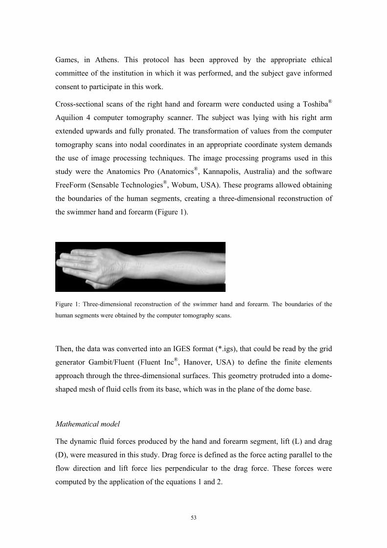
Games, in Athens. This protocol has been approved by the appropriate ethical
committee of the institution in which it was performed, and the subject gave informed
consent to participate in this work.
Cross-sectional scans of the right hand and forearm were conducted using a Toshiba®
Aquilion 4 computer tomography scanner. The subject was lying with his right arm
extended upwards and fully pronated. The transformation of values from the computer
tomography scans into nodal coordinates in an appropriate coordinate system demands
the use of image processing techniques. The image processing programs used in this
study were the Anatomics Pro (Anatomics®, Kannapolis, Australia) and the software
FreeForm (Sensable Technologies®, Wobum, USA). These programs allowed obtaining
the boundaries of the human segments, creating a three-dimensional reconstruction of
the swimmer hand and forearm (Figure 1).
Figure 1: Three-dimensional reconstruction of the swimmer hand and forearm. The boundaries of the
human segments were obtained by the computer tomography scans.
Then, the data was converted into an IGES format (*.igs), that could be read by the grid
generator Gambit/Fluent (Fluent Inc®, Hanover, USA) to define the finite elements
approach through the three-dimensional surfaces. This geometry protruded into a dome-
shaped mesh of fluid cells from its base, which was in the plane of the dome base.
Mathematical model
The dynamic fluid forces produced by the hand and forearm segment, lift (L) and drag
(D), were measured in this study. Drag force is defined as the force acting parallel to the
flow direction and lift force lies perpendicular to the drag force. These forces were
computed by the application of the equations 1 and 2.
53
2
21 ρSVCD D=
(1)
2
21 ρSVCL L=
(2)
In equations 1 and 2, CD and CL represent the drag and lift coefficients, respectively, V
represents the water velocity, ρ represents the fluid density and S represents the
projection surface of the model for different angles of attack used in this study.
The numerical simulation techniques methodology consists of a mathematical model
applied to the fluid flow in a given domain that replaces the Navier-Stokes equations
with discretized algebraic expressions. These equations can be solved by iterative
computerised calculations. The Fluent CFD code (Fluent®, Inc. Hannover, USA), was
used to develop and solve these equations using the finite volume approach, where the
equations were integrated over each control volume. The domain consists of a three-
dimensional grid or mesh of cells that simulate the fluid flow around the human
segments.
We used the segregated solver with the standard k-epsilon turbulence model because
this turbulence model was shown to be accurate with measured values in a previous
research (Moreira et al., 2006). All numerical computational schemes were second-
order, which provides a more accurate solution than first-order schemes. The considered
fluid was water, with a turbulence intensity of 1.0% and a turbulence scale of 0.10 m.
The water density was 998.2 kg/m3 with a viscosity of 0.001 kg/mm/s.
Boundary conditions
The numerical simulations were carried out in three-dimensions for the computational
domain in steady flow. A three-dimensional domain was designed to simulate the fluid
flow around a swimmer hand and forearm model (Figure 2). The whole domain was
meshed with 900 thousand cells. The grid was a hybrid mesh composed of prisms and
pyramids. Significant efforts were conducted to ensure that the model would provide
accurate results, namely by decreasing the grid node separation in areas of high velocity
54
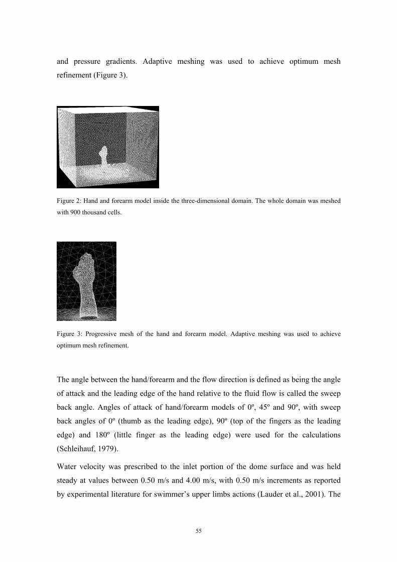
and pressure gradients. Adaptive meshing was used to achieve optimum mesh
refinement (Figure 3).
Figure 2: Hand and forearm model inside the three-dimensional domain. The whole domain was meshed
with 900 thousand cells.
Figure 3: Progressive mesh of the hand and forearm model. Adaptive meshing was used to achieve
optimum mesh refinement.
The angle between the hand/forearm and the flow direction is defined as being the angle
of attack and the leading edge of the hand relative to the fluid flow is called the sweep
back angle. Angles of attack of hand/forearm models of 0º, 45º and 90º, with sweep
back angles of 0º (thumb as the leading edge), 90º (top of the fingers as the leading
edge) and 180º (little finger as the leading edge) were used for the calculations
(Schleihauf, 1979).
Water velocity was prescribed to the inlet portion of the dome surface and was held
steady at values between 0.50 m/s and 4.00 m/s, with 0.50 m/s increments as reported
by experimental literature for swimmer’s upper limbs actions (Lauder et al., 2001). The
55
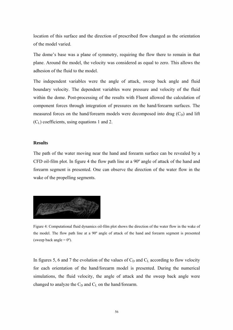
location of this surface and the direction of prescribed flow changed as the orientation
of the model varied.
The dome’s base was a plane of symmetry, requiring the flow there to remain in that
plane. Around the model, the velocity was considered as equal to zero. This allows the
adhesion of the fluid to the model.
The independent variables were the angle of attack, sweep back angle and fluid
boundary velocity. The dependent variables were pressure and velocity of the fluid
within the dome. Post-processing of the results with Fluent allowed the calculation of
component forces through integration of pressures on the hand/forearm surfaces. The
measured forces on the hand/forearm models were decomposed into drag (CD) and lift
(CL) coefficients, using equations 1 and 2.
Results
The path of the water moving near the hand and forearm surface can be revealed by a
CFD oil-film plot. In figure 4 the flow path line at a 90º angle of attack of the hand and
forearm segment is presented. One can observe the direction of the water flow in the
wake of the propelling segments.
Figure 4: Computational fluid dynamics oil-film plot shows the direction of the water flow in the wake of
the model. The flow path line at a 90º angle of attack of the hand and forearm segment is presented
(sweep back angle = 0º).
In figures 5, 6 and 7 the evolution of the values of CD and CL according to flow velocity
for each orientation of the hand/forearm model is presented. During the numerical
simulations, the fluid velocity, the angle of attack and the sweep back angle were
changed to analyze the CD and CL on the hand/forearm.
56
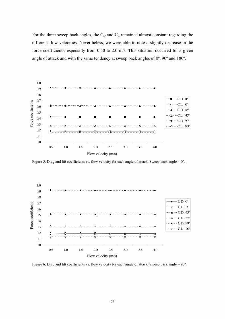
For the three sweep back angles, the CD and CL remained almost constant regarding the
different flow velocities. Nevertheless, we were able to note a slightly decrease in the
force coefficients, especially from 0.50 to 2.0 m/s. This situation occurred for a given
angle of attack and with the same tendency at sweep back angles of 0º, 90º and 180º.
0.0
0.1
0.2
0.3
0.4
0.5
0.6
0.7
0.8
0.9
1.0
0.5 1.0 1.5 2.0 2.5 3.0 3.5 4.0
C D 0ºC L 0ºC D 45ºC L 45ºC D 90ºC L 90º
Forc
e co
effic
ient
s
Flow velocity (m/s)
Figure 5: Drag and lift coefficients vs. flow velocity for each angle of attack. Sweep back angle = 0º.
0.0
0.1
0.2
0.3
0.4
0.5
0.6
0.7
0.8
0.9
1.0
0.5 1.0 1.5 2.0 2.5 3.0 3.5 4.0
C D 0ºC L 0ºC D 45ºC L 45ºC D 90ºC L 90º
Forc
e co
effic
ient
s
Flow velocity (m/s)
Figure 6: Drag and lift coefficients vs. flow velocity for each angle of attack. Sweep back angle = 90º.
57
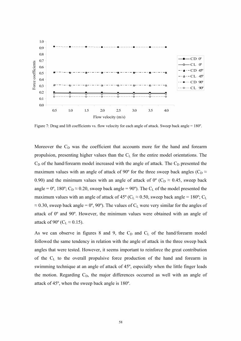
0.0
0.1
0.2
0.3
0.4
0.5
0.6
0.7
0.8
0.9
1.0
0.5 1.0 1.5 2.0 2.5 3.0 3.5 4.0
C D 0ºC L 0ºC D 45ºC L 45ºC D 90ºC L 90º
Forc
e co
effic
ient
s
Flow velocity (m/s)
Figure 7: Drag and lift coefficients vs. flow velocity for each angle of attack. Sweep back angle = 180º.
Moreover the CD was the coefficient that accounts more for the hand and forearm
propulsion, presenting higher values than the CL for the entire model orientations. The
CD of the hand/forearm model increased with the angle of attack. The CD presented the
maximum values with an angle of attack of 90º for the three sweep back angles (CD ≈
0.90) and the minimum values with an angle of attack of 0º (CD ≈ 0.45, sweep back
angle = 0º, 180º; CD ≈ 0.20, sweep back angle = 90º). The CL of the model presented the
maximum values with an angle of attack of 45º (CL ≈ 0.50, sweep back angle = 180º; CL
≈ 0.30, sweep back angle = 0º, 90º). The values of CL were very similar for the angles of
attack of 0º and 90º. However, the minimum values were obtained with an angle of
attack of 90º (CL ≈ 0.15).
As we can observe in figures 8 and 9, the CD and CL of the hand/forearm model
followed the same tendency in relation with the angle of attack in the three sweep back
angles that were tested. However, it seems important to reinforce the great contribution
of the CL to the overall propulsive force production of the hand and forearm in
swimming technique at an angle of attack of 45º, especially when the little finger leads
the motion. Regarding CD, the major differences occurred as well with an angle of
attack of 45º, when the sweep back angle is 180º.
58
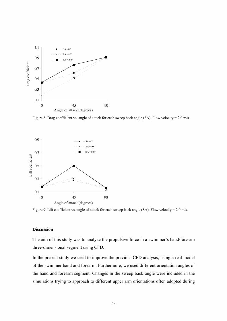
0.1
0.3
0.5
0.7
0.9
1.1
0 45 90
SA = 0º
SA = 90º
SA = 180º
Dra
g co
effic
ient
Angle of attack (degrees)
Figure 8: Drag coefficient vs. angle of attack for each sweep back angle (SA). Flow velocity = 2.0 m/s.
0.1
0.3
0.5
0.7
0.9
0 45 90
SA = 0º
SA = 90º
SA = 180º
Lift
coef
ficie
nt
Angle of attack (degrees)
Figure 9: Lift coefficient vs. angle of attack for each sweep back angle (SA). Flow velocity = 2.0 m/s.
Discussion
The aim of this study was to analyze the propulsive force in a swimmer’s hand/forearm
three-dimensional segment using CFD.
In the present study we tried to improve the previous CFD analysis, using a real model
of the swimmer hand and forearm. Furthermore, we used different orientation angles of
the hand and forearm segment. Changes in the sweep back angle were included in the
simulations trying to approach to different upper arm orientations often adopted during
59
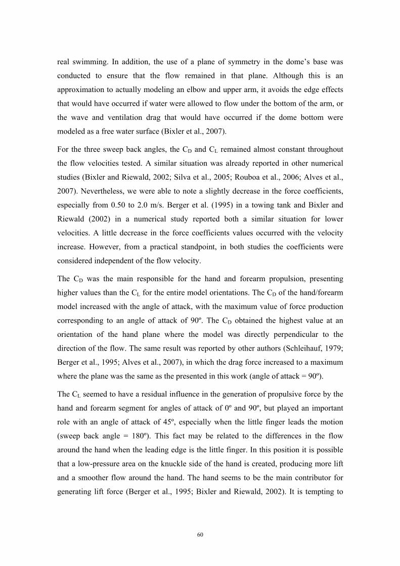
real swimming. In addition, the use of a plane of symmetry in the dome’s base was
conducted to ensure that the flow remained in that plane. Although this is an
approximation to actually modeling an elbow and upper arm, it avoids the edge effects
that would have occurred if water were allowed to flow under the bottom of the arm, or
the wave and ventilation drag that would have occurred if the dome bottom were
modeled as a free water surface (Bixler et al., 2007).
For the three sweep back angles, the CD and CL remained almost constant throughout
the flow velocities tested. A similar situation was already reported in other numerical
studies (Bixler and Riewald, 2002; Silva et al., 2005; Rouboa et al., 2006; Alves et al.,
2007). Nevertheless, we were able to note a slightly decrease in the force coefficients,
especially from 0.50 to 2.0 m/s. Berger et al. (1995) in a towing tank and Bixler and
Riewald (2002) in a numerical study reported both a similar situation for lower
velocities. A little decrease in the force coefficients values occurred with the velocity
increase. However, from a practical standpoint, in both studies the coefficients were
considered independent of the flow velocity.
The CD was the main responsible for the hand and forearm propulsion, presenting
higher values than the CL for the entire model orientations. The CD of the hand/forearm
model increased with the angle of attack, with the maximum value of force production
corresponding to an angle of attack of 90º. The CD obtained the highest value at an
orientation of the hand plane where the model was directly perpendicular to the
direction of the flow. The same result was reported by other authors (Schleihauf, 1979;
Berger et al., 1995; Alves et al., 2007), in which the drag force increased to a maximum
where the plane was the same as the presented in this work (angle of attack = 90º).
The CL seemed to have a residual influence in the generation of propulsive force by the
hand and forearm segment for angles of attack of 0º and 90º, but played an important
role with an angle of attack of 45º, especially when the little finger leads the motion
(sweep back angle = 180º). This fact may be related to the differences in the flow
around the hand when the leading edge is the little finger. In this position it is possible
that a low-pressure area on the knuckle side of the hand is created, producing more lift
and a smoother flow around the hand. The hand seems to be the main contributor for
generating lift force (Berger et al., 1995; Bixler and Riewald, 2002). It is tempting to
60
compare the hand with a wing-shaped hydrofoil. For such profiles it is known that the
value of the CL is dependent on the angle of attack. It is not expected that hands have
the full characteristics of such lift force generators. However, hands can certainly
generate some lift force, depending on the hand orientation with respect to the flow.
Further research during actual swimming is necessary to establish the orientation and
movement of the hand in which the forward component of the sum of drag and lift
forces is maximal. Moreover, since distinct patterns of timing and sequence of body roll
on front crawl and backstroke are used by the swimmers (Lee et al., 2008) the effect of
this rotation on the propulsive force production should be simulated. Considering these
results, it seems essential to analyze a larger range of angles of attack, trying to clarify
the true importance of the lift force to the propulsive force production. The CD has its
maximum values if the flow vector is at right angles to the hand plane, whereas the CL
has its maximum values if the hand plane makes an angle with the flow vector. It seems
probable that the lift force plays an important role at other angles of attack rather than
the 45º, as it is suggested by Schleihauf (1979) at an attack angle of 15º.
In summary, the CD was the main responsible for the hand/forearm propulsion with a
maximum value at an angle of attack of 90º. The CL seems to play an important role at
an angle of attack of 45º, especially when the little finger leads the motion. These data
confirm recent studies reporting supremacy of drag component and an important
contribution of lift force to the overall propulsive force generation by the hand/forearm
in swimming phases, when the angle of attack nears 45º.
The results have demonstrated this numerical tool can effectively be used both to
improve the foundational knowledge of swimming hydrodynamics as well as to provide
useful practical information to coaches and swimmers. Ideally, with increases in the
database of information created by the CFD analysis, more conclusions could be
derived which could be applicable to larger swimming populations. Further studies
should include the unsteady effects of motion, such as accelerations, decelerations and
multi-axis rotations. This could be accomplished by performing transient time-
dependent analysis using user-defined functions and moving meshes (Lyttle and Keys,
2006). The ultimate goal should be to use this numerical technique to evaluate complete
arm and leg strokes and to prescribe the optimum pulling pattern.
61
References
Alves, F., Marinho, D., Leal, L., Rouboa, A., Silva, A. (2007). 3-D computational fluid dynamics of the
hand and forearm in swimming. Medicine and Science in Sports and Exercise, 39(Suppl. 1), S9.
Berger, M.A.M., de Groot, G., Hollander, P. (1995). Hydrodynamic drag and lift forces on human
hand/arm models. Journal of Biomechanics, 28, 125-133.
Bixler, B., Schloder, M. (1996). Computational fluid dynamics: an analytical tool for the 21st century
swimming scientist. Journal of Swimming Research, 11, 4-22.
Bixler, B., Riewald, S. (2002). Analysis of swimmer’s hand and arm in steady flow conditions using
computational fluid dynamics. Journal of Biomechanics, 35, 713-717.
Bixler, B., Pease, D., Fairhurst, F. (2007). The accuracy of computational fluid dynamics analysis of the
passive drag of a male swimmer. Sports Biomechanics, 6, 81-98.
Chatard, J.C., Lavoie, J.M., Bourgoins, B., Lacour, J.R. (1990). The contribution of passive drag as a
determinant of swimming performance. International Journal of Sports Medicine, 11, 367-372.
Gardano, P., Dabnichki, P. (2006). On hydrodynamics of drag and lift of the human arm. Journal of
Biomechanics, 39, 2767-2773.
Hollander, A.P., de Groot, G., Van Ingen Schenau, G.L., Toussaint, H.M., de Best, H., Peeters, W.,
Meulemans, A., Schreurs, A.W. (1986). Measurement of active drag during crawl arm stroke
swimming. Journal of Sports Sciences, 4, 21-30.
Lauder, M., Dabnichki, P., Bartlett, R. (2001). Improved accuracy and reliability of sweepback angle,
pitch angle and hand velocity calculations in swimming. Journal of Biomechanics, 34, 31-39.
Lee, J., Mellifont, R., Winstanley, J., Burkett, B. (2008). Body roll in simulated freestyle swimming.
International Journal of Sports Medicine, 29, 569-573.
Lyttle, A., Keys, M. (2006). The application of computational fluid dynamics for technique prescription
in underwater kicking. Portuguese Journal of Sport Sciences, 6(Suppl. 2), 233-235.
Moreira, A., Rouboa, A., Silva, A.J., Sousa, L., Marinho, D., Alves, F., Reis, V., Vilas-Boas, J.P.,
Carneiro, A., Machado, L. (2006). Computational analysis of the turbulent flow around a cylinder.
Portuguese Journal of Sport Sciences, 6(Suppl. 1), 105.
Payton, C., Bartlett, R. (1995). Estimating propulsive forces in swimming from three-dimensional
kinematic data. Journal of Sports Sciences, 13, 447-454.
Rouboa, A., Silva, A., Leal, L., Rocha, J., Alves, F. (2006). The effect of swimmer’s hand/forearm
acceleration on propulsive forces generation using computational fluid dynamics. Journal of
Biomechanics, 39, 1239-1248.
62

Sanders, R.H. (1999). Hydrodynamic characteristics of a swimmer’s hand. Journal of Applied
Biomechanics, 15, 3-26.
Schleihauf, R.E. (1979). A hydrodynamic analysis of swimming propulsion. In: J. Terauds, E.W.
Bedingfield (Eds.), Swimming III, pp. 70-109. Baltimore: University Park Press.
Silva, A., Rouboa, A., Leal, L., Rocha, J., Alves, F., Moreira, A., Reis, V., Vilas-Boas, J.P. (2005).
Measurement of swimmer's hand/forearm propulsive forces generation using computational fluid
dynamics. Portuguese Journal of Sport Sciences, 5, 288-297.
63
Study 5
Hydrodynamic analysis of different thumb positions in swimming
Marinho, D.A., Rouboa, A.I., Alves, F.B., Vilas-Boas, J.P., Machado, L., Reis, V.M., Silva, A.J. (2008).
Hydrodynamic analysis of different thumb positions in swimming. Journal of Sports Science and
Medicine (in press).
64
Hydrodynamic analysis of different thumb positions in swimming
Abstract
The aim of the present study was to analyze the hydrodynamic characteristics of a true model of a
swimmer hand with the thumb in different positions using numerical simulation techniques. A three-
dimensional domain was created to simulate the fluid flow around three models of a swimmer hand, with
the thumb in different positions: thumb fully abducted, partially abducted, and adducted. These three hand
models were obtained through computerized tomography scans of an Olympic swimmer hand. Steady-
state computational fluid dynamics analyses were performed using the Fluent® code. The forces estimated
in each of the three hand models were decomposed into drag and lift coefficients. Angles of attack of
hand models of 0º, 45º and 90º, with a sweep back angle of 0º were used for the calculations. The results
showed that the position with the thumb adducted presented slightly higher values of drag coefficient
compared with thumb abducted positions. Moreover, the position with the thumb fully abducted allowed
increasing the lift coefficient of the hand at angles of attack of 0º and 45º. These results suggested that,
for hand models in which the lift force can play an important role, the abduction of the thumb may be
better, whereas at higher angles of attack, in which the drag force is dominant, the adduction of the thumb
may be preferable.
Introduction
The numerical simulation technique is currently one of the best established numerical
tools in the field of biomechanical engineering. This methodology has been used in the
computational analysis of the fluid flow in several research fields, such as medicine,
biology, industry and sports (e.g. Boulding et al., 2002; Marshall et al., 2004; Guerra et
al., 2007; Dabnichki and Avital, 2006). This numerical tool is a branch of fluid
mechanics that solves and analyses problems involving a fluid flow by means of
computer-based simulations. Thus, one of the major benefits is to quickly answer many
'what if?' questions. It is possible to test many variations to seek for an optimal result,
without human experimental testing. The user is able to computationally model any
flow field, provided the geometry of the object is known and some initial flow
conditions are prescribed. This can provide answers and insights into problems which
have been unavailable or obtainable with very expensive costs (using physical or
experimental testing techniques). As such, numerical simulation techniques can be seen
as bridging the gap between theoretical and experimental fluid dynamics.
65
In sports scope, the main results suggested that the numerical analysis could provide
useful information about performance. Indeed, the use of numerical simulation
techniques has produced significant improvements in equipment design and technique
prescription in areas such as sailing performance (Pallis et al., 2000), Formula 1 racing
(Kellar et al., 1999) and winter sports (Dabnichki and Avital, 2006). In swimming, this
methodology has been used to study the propulsive forces produced by the hand and
forearm in swimming (Bixler and Schloder, 1996; Silva et al., 2005; Gardano and
Dabnichki, 2006; Rouboa et al., 2006; Lecrivain et al., 2008) and the magnitude of drag
forces resisting forward motion (Marinho et al., 2008a; Silva et al., 2008; Zaidi et al.,
2008). However, a common weakness still remains: practically all the models that have
been developed are based on approximate analytical representations of the human
structures and their geometrical accuracy has never been discussed. This approach has
been commonly adopted, for example, to reduce the computational cost of memory
requirements (Aritan et al., 1997). One of the main reasons for such limitations is the
difficulty to design a true digital model of the human limbs. In most cases, the authors
used two-dimensional models (Bixler and Schloder, 1996; Silva et al., 2005; Rouboa et
al., 2006; Silva et al., 2008; Zaidi et al., 2008). When three-dimensional models were
used, these were very simple and reductive representations of the human limbs
(Gardano and Dabnichki, 2006). Gardano and Dabnickki (2006) used standard
geometrical solids to represent the upper limb, which leaded to significant differences
between the human limb and the digital model. These differences between true and
computed models could lead to less accurate numerical results (Candalai and Reddy,
1992). In fact, Candalai and Reddy (1992) conducted a simulation of the effect of the
ischial tuberosity’s geometry on the shear and compressive stress in buttock issue and
showed that the influence of the geometry on the stress magnitude could be significant.
A possible variation of more than 60% in the shear stress was found. Despite the
differences between the aims of the work of Candalai and Reddy (1992) and swimming
studies, one should be aware of the ecological validity of the data that is obtained,
stressing the relevance of the scanned models instead of analytical representations.
Moreover, it should be noted that mesh generation, the first step of numerical
simulations, is a tough procedure, especially when solving three-dimensional problems.
66
Thus, it should be based on directly obtained anatomical data (Aritan et al., 1997;
Lecrivain et al., 2008; Marinho et al., 2008b).
Magnetic resonance imaging, computer tomography scans and laser scans seem to be a
good approach to design true human models (Aritan et al., 1997; Marshall et al., 2004;
Lecrivain et al., 2008; Marinho et al., 2008b). The overall aim of this approach, also
called reverse engineering process, is to build a virtual model geometrically identical to
an existing object. Scanning and data manipulation are the two main parts in this
process. Briefly one needs to gather the requisite data from a three-dimensional object
and then to edit the data and translate it into more suitable formats such as surface
models (Lecrivain et al., 2008).
Using a true model of the human body it is possible to improve the quality of the
numerical simulations techniques and to provide insights into some questions that
remain unclear in swimming technique. The thumb’s relative position during the
underwater path of the stroke cycle is one of these questions. An inter-subject variety of
thumb position can be observed among elite swimmers. Some swimmers maintain the
thumb adducted, others maintain the thumb abducted and others maintain the thumb
partially abducted. In fact, there remains much to be learned on the effect of thumb
position and whereas similar results are obtained by different methods of testing
(Takagi et al., 2001). Schleihauf (1979) showed that a thumb partially abducted allows
higher propulsion. Berger et al. (1997) found that models with different thumb
abduction/adduction had very little effect on drag forces but an effect on lift forces.
Takagi et al. (2001) reported that adduction and abduction of the thumb influenced the
lift force. The thumb abducted seemed to be advantageous for generating lift force when
the thumb is the leading edge and the thumb adducted seemed to be advantageous when
the little finger leads the motion (Takagi et al., 2001). To our knowledge, there is no
research published using a numerical approach on the repercussion of thumb
abduction/adduction and with anthropometrical data of elite swimmers’ hand.
Therefore, the aim of the present study was to analyze the hydrodynamic characteristics
of a true model of a swimmer hand with the thumb in different positions using
numerical simulation techniques.
67
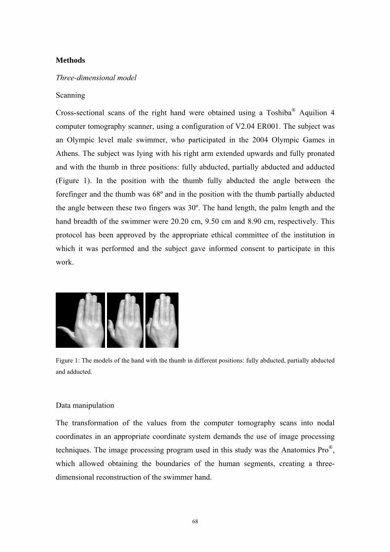
Methods
Three-dimensional model
Scanning
Cross-sectional scans of the right hand were obtained using a Toshiba® Aquilion 4
computer tomography scanner, using a configuration of V2.04 ER001. The subject was
an Olympic level male swimmer, who participated in the 2004 Olympic Games in
Athens. The subject was lying with his right arm extended upwards and fully pronated
and with the thumb in three positions: fully abducted, partially abducted and adducted
(Figure 1). In the position with the thumb fully abducted the angle between the
forefinger and the thumb was 68º and in the position with the thumb partially abducted
the angle between these two fingers was 30º. The hand length, the palm length and the
hand breadth of the swimmer were 20.20 cm, 9.50 cm and 8.90 cm, respectively. This
protocol has been approved by the appropriate ethical committee of the institution in
which it was performed and the subject gave informed consent to participate in this
work.
Figure 1: The models of the hand with the thumb in different positions: fully abducted, partially abducted
and adducted.
Data manipulation
The transformation of the values from the computer tomography scans into nodal
coordinates in an appropriate coordinate system demands the use of image processing
techniques. The image processing program used in this study was the Anatomics Pro®,
which allowed obtaining the boundaries of the human segments, creating a three-
dimensional reconstruction of the swimmer hand.
68
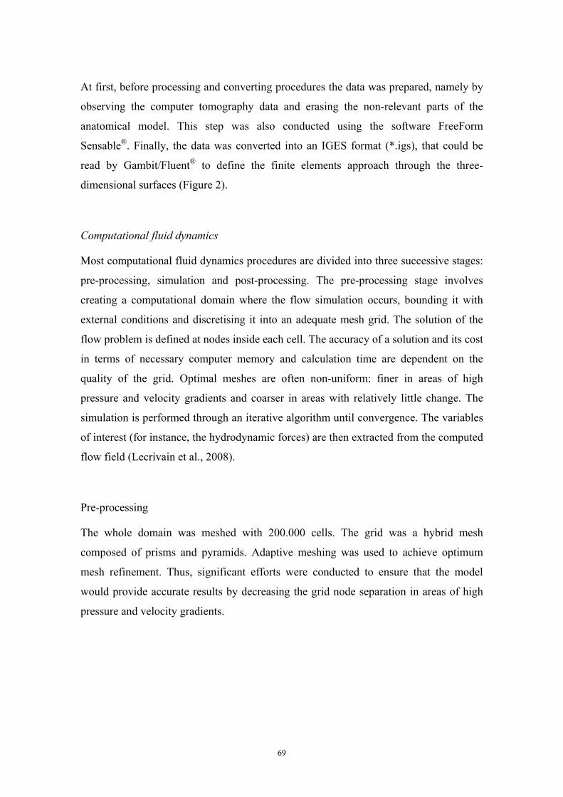
At first, before processing and converting procedures the data was prepared, namely by
observing the computer tomography data and erasing the non-relevant parts of the
anatomical model. This step was also conducted using the software FreeForm
Sensable®. Finally, the data was converted into an IGES format (*.igs), that could be
read by Gambit/Fluent® to define the finite elements approach through the three-
dimensional surfaces (Figure 2).
Computational fluid dynamics
Most computational fluid dynamics procedures are divided into three successive stages:
pre-processing, simulation and post-processing. The pre-processing stage involves
creating a computational domain where the flow simulation occurs, bounding it with
external conditions and discretising it into an adequate mesh grid. The solution of the
flow problem is defined at nodes inside each cell. The accuracy of a solution and its cost
in terms of necessary computer memory and calculation time are dependent on the
quality of the grid. Optimal meshes are often non-uniform: finer in areas of high
pressure and velocity gradients and coarser in areas with relatively little change. The
simulation is performed through an iterative algorithm until convergence. The variables
of interest (for instance, the hydrodynamic forces) are then extracted from the computed
flow field (Lecrivain et al., 2008).
Pre-processing
The whole domain was meshed with 200.000 cells. The grid was a hybrid mesh
composed of prisms and pyramids. Adaptive meshing was used to achieve optimum
mesh refinement. Thus, significant efforts were conducted to ensure that the model
would provide accurate results by decreasing the grid node separation in areas of high
pressure and velocity gradients.
69
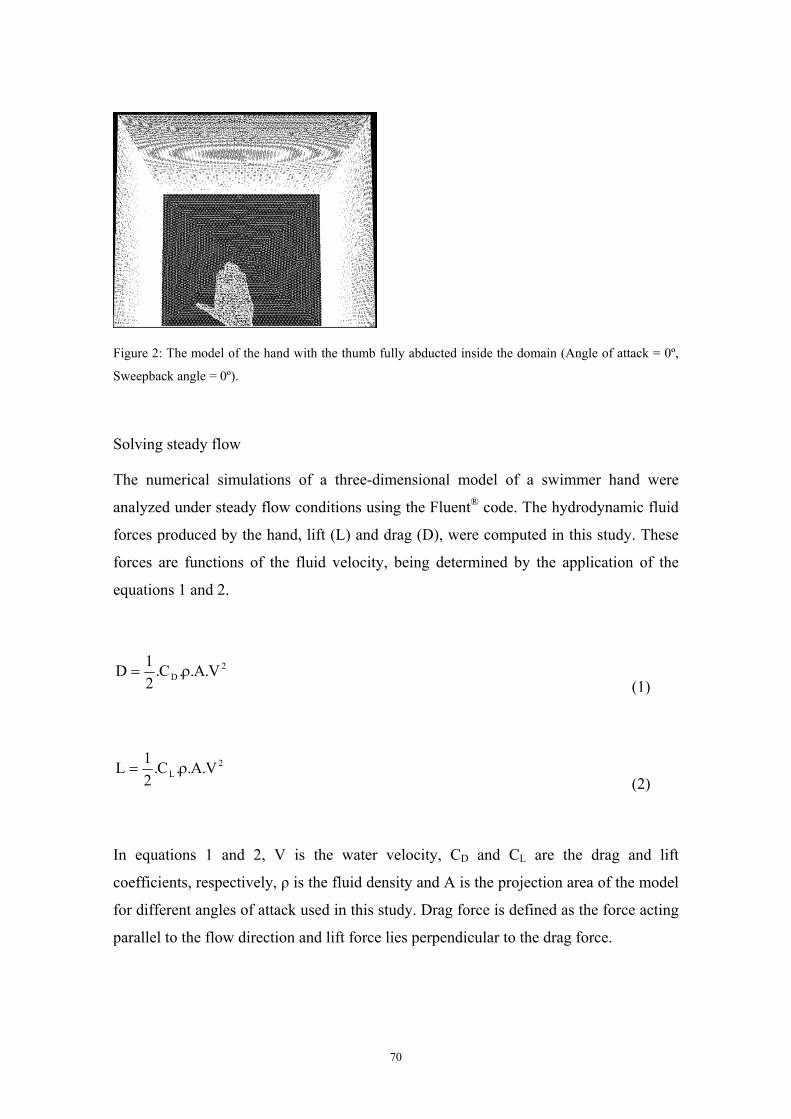
Figure 2: The model of the hand with the thumb fully abducted inside the domain (Angle of attack = 0º,
Sweepback angle = 0º).
Solving steady flow
The numerical simulations of a three-dimensional model of a swimmer hand were
analyzed under steady flow conditions using the Fluent® code. The hydrodynamic fluid
forces produced by the hand, lift (L) and drag (D), were computed in this study. These
forces are functions of the fluid velocity, being determined by the application of the
equations 1 and 2.
2D V.A..C.
21D ρ=
(1)
2L V.A..C.
21L ρ=
(2)
In equations 1 and 2, V is the water velocity, CD and CL are the drag and lift
coefficients, respectively, ρ is the fluid density and A is the projection area of the model
for different angles of attack used in this study. Drag force is defined as the force acting
parallel to the flow direction and lift force lies perpendicular to the drag force.
70
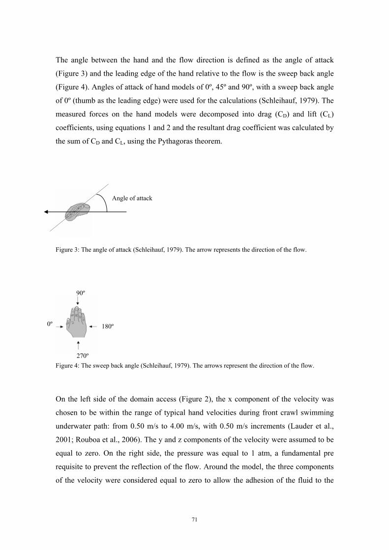
The angle between the hand and the flow direction is defined as the angle of attack
(Figure 3) and the leading edge of the hand relative to the flow is the sweep back angle
(Figure 4). Angles of attack of hand models of 0º, 45º and 90º, with a sweep back angle
of 0º (thumb as the leading edge) were used for the calculations (Schleihauf, 1979). The
measured forces on the hand models were decomposed into drag (CD) and lift (CL)
coefficients, using equations 1 and 2 and the resultant drag coefficient was calculated by
the sum of CD and CL, using the Pythagoras theorem.
Angle of attack
Figure 3: The angle of attack (Schleihauf, 1979). The arrow represents the direction of the flow.
90º
0º 180º
270º Figure 4: The sweep back angle (Schleihauf, 1979). The arrows represent the direction of the flow.
On the left side of the domain access (Figure 2), the x component of the velocity was
chosen to be within the range of typical hand velocities during front crawl swimming
underwater path: from 0.50 m/s to 4.00 m/s, with 0.50 m/s increments (Lauder et al.,
2001; Rouboa et al., 2006). The y and z components of the velocity were assumed to be
equal to zero. On the right side, the pressure was equal to 1 atm, a fundamental pre
requisite to prevent the reflection of the flow. Around the model, the three components
of the velocity were considered equal to zero to allow the adhesion of the fluid to the
71
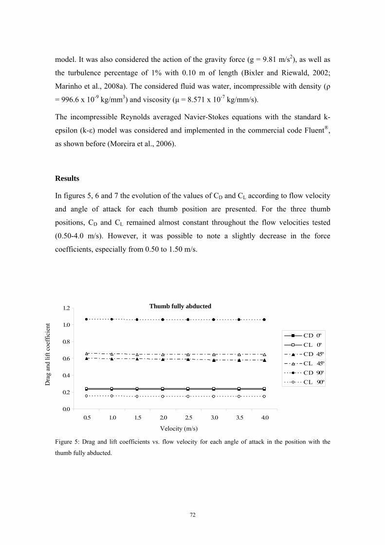
model. It was also considered the action of the gravity force (g = 9.81 m/s2), as well as
the turbulence percentage of 1% with 0.10 m of length (Bixler and Riewald, 2002;
Marinho et al., 2008a). The considered fluid was water, incompressible with density (ρ
= 996.6 x 10⁻⁹ kg/mm3) and viscosity (μ = 8.571 x 10⁻⁷ kg/mm/s).
The incompressible Reynolds averaged Navier-Stokes equations with the standard k-
epsilon (k-ε) model was considered and implemented in the commercial code Fluent®,
as shown before (Moreira et al., 2006).
Results
In figures 5, 6 and 7 the evolution of the values of CD and CL according to flow velocity
and angle of attack for each thumb position are presented. For the three thumb
positions, CD and CL remained almost constant throughout the flow velocities tested
(0.50-4.0 m/s). However, it was possible to note a slightly decrease in the force
coefficients, especially from 0.50 to 1.50 m/s.
0.0
0.2
0.4
0.6
0.8
1.0
1.2
0.5 1.0 1.5 2.0 2.5 3.0 3.5 4.0
C D 0ºC L 0ºC D 45ºC L 45ºC D 90ºC L 90º
Thumb fully abducted
Dra
g an
d lif
t coe
ffic
ient
Velocity (m/s)
Figure 5: Drag and lift coefficients vs. flow velocity for each angle of attack in the position with the
thumb fully abducted.
72
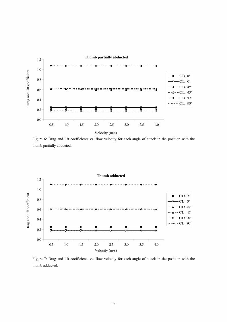
0.0
0.2
0.4
0.6
0.8
1.0
1.2
0.5 1.0 1.5 2.0 2.5 3.0 3.5 4.0
C D 0ºC L 0ºC D 45ºC L 45ºC D 90ºC L 90º
Thumb partially abducted
Dra
g an
d lif
t coe
ffic
ient
Figure 6: Drag and lift coefficients vs. flow velocity for each angle of attack in the position with the
thumb partially abducted.
Velocity (m/s)
0.0
0.2
0.4
0.6
0.8
1.0
1.2
0.5 1.0 1.5 2.0 2.5 3.0 3.5 4.0
C D 0ºC L 0ºC D 45ºC L 45ºC D 90ºC L 90º
Thumb adducted
Dra
g an
d lif
t coe
ffic
ient
Velocity (m/s)
Figure 7: Drag and lift coefficients vs. flow velocity for each angle of attack in the position with the
thumb adducted.
73
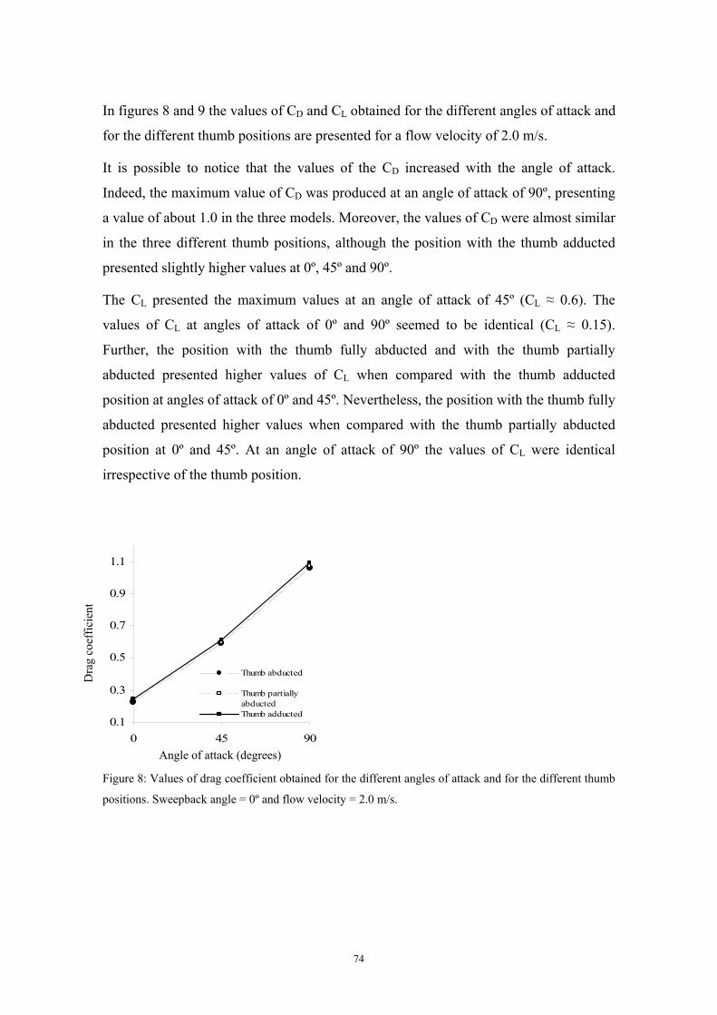
In figures 8 and 9 the values of CD and CL obtained for the different angles of attack and
for the different thumb positions are presented for a flow velocity of 2.0 m/s.
It is possible to notice that the values of the CD increased with the angle of attack.
Indeed, the maximum value of CD was produced at an angle of attack of 90º, presenting
a value of about 1.0 in the three models. Moreover, the values of CD were almost similar
in the three different thumb positions, although the position with the thumb adducted
presented slightly higher values at 0º, 45º and 90º.
The CL presented the maximum values at an angle of attack of 45º (CL ≈ 0.6). The
values of CL at angles of attack of 0º and 90º seemed to be identical (CL ≈ 0.15).
Further, the position with the thumb fully abducted and with the thumb partially
abducted presented higher values of CL when compared with the thumb adducted
position at angles of attack of 0º and 45º. Nevertheless, the position with the thumb fully
abducted presented higher values when compared with the thumb partially abducted
position at 0º and 45º. At an angle of attack of 90º the values of CL were identical
irrespective of the thumb position.
0.1
0.3
0.5
0.7
0.9
1.1
0 45
Dra
g co
effic
ient
90
Thumb abducted
Thumb partiallyabductedThumb adducted
Angle of attack (degrees)
Figure 8: Values of drag coefficient obtained for the different angles of attack and for the different thumb
positions. Sweepback angle = 0º and flow velocity = 2.0 m/s.
74
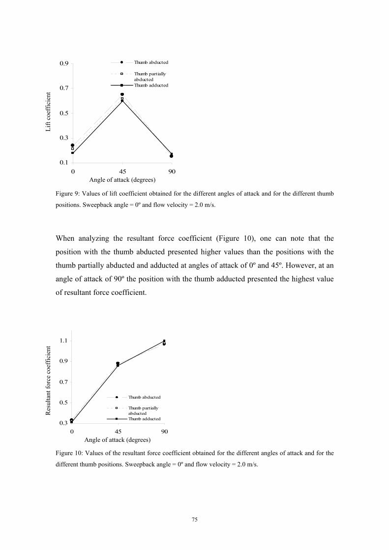
0.1
0.3
0.5
0.7
0.9
0 45 90
Thumb abducted
Thumb partiallyabductedThumb adducted
Lift
coef
ficie
nt
Angle of attack (degrees)
Figure 9: Values of lift coefficient obtained for the different angles of attack and for the different thumb
positions. Sweepback angle = 0º and flow velocity = 2.0 m/s.
When analyzing the resultant force coefficient (Figure 10), one can note that the
position with the thumb abducted presented higher values than the positions with the
thumb partially abducted and adducted at angles of attack of 0º and 45º. However, at an
angle of attack of 90º the position with the thumb adducted presented the highest value
of resultant force coefficient.
0.3
0.5
0.7
0.9
1.1
0 45
Res
ulta
nt fo
rce
coef
ficie
nt
90
Thumb abducted
Thumb partiallyabductedThumb adducted
Angle of attack (degrees)
Figure 10: Values of the resultant force coefficient obtained for the different angles of attack and for the
different thumb positions. Sweepback angle = 0º and flow velocity = 2.0 m/s.
75
Discussion
The aim of the present study was to analyze the hydrodynamic characteristics of a true
model of a swimmer hand with the thumb in different positions using numerical
simulation techniques.
In this research we tried to improve the previous studies that applied the numerical
techniques to the analysis of swimming propulsion, using a more realistic model of the
swimmer hand. Indeed, the computer tomography scans allowed the creation of a
complete and true digital anatomic model of a swimmer hand (Aritan et al., 1997).
One of the major benefits of the numerical simulation procedures is that it allows the
user to modify the inputs into the model to determine how its changes affect the
resultant flow conditions. Regarding swimming, changes in technique can be examined
using the model, rather than the “trial and error” approach that typically is used. In this
work we have analysed the hydrodynamic forces produced by the swimmer hand with
the thumb in different positions as used by high level swimmers.
For the three thumb positions, the CD and CL remained almost constant throughout the
flow velocities that were tested. A similar observation was already reported in other
numerical studies (Bixler and Riewald, 2002; Silva et al., 2005; Rouboa et al., 2006;
Alves et al., 2007). However, in the present study, a slightly decrease in the CD and CL
were noted, especially from 0.50 to 1.50 m/s. Berger et al. (1995) and Bixler and
Riewald (2002) observed a similar tendency for lower velocities, in a towing tank
experiment and using numerical techniques, respectively. For lower velocities, a very
small decrease in the force coefficients values occurred with the velocity increase.
However, from a practical standpoint, the coefficients were considered constant since
the forces at these velocities are relatively small (Bixler and Riewald, 2002).
The values of CD produced by the swimmer hand were very similar concerning the three
thumb positions. However, the position with the thumb adducted presented slightly
higher values at the angles of attack tested in this study. Moreover, the values of CL
changed with the thumb position at angles of attack of 0º and 45º, although at an angle
of attack of 90º the values of the different thumb positions were identical. At 0º and 45º,
the position with the thumb fully abducted presented the highest values of CL.
76
Schleihauf (1979) studied the changes in the values of CL as a function of the thumb
position (thumb 100% abducted, 75% abducted and 50% abducted). However the
authors did not study the CD nor the position with the thumb adducted. In the study of
Schleihauf (1979), the position with the thumb fully abducted showed a maximum CL at
an acute angle of attack of 15º, whereas the models with partial thumb abduction
showed a maximum value of CL at higher angles of attack (45º-60º). In these angles of
attack the position with the thumb partially abducted presented higher values when
compared with the thumb fully abducted. Berger et al. (1997) reported that the thumb
position determined lift forces, although the drag forces were not influenced by thumb
abduction/adduction. Moreover, Takagi et al. (2001) estimated the drag and lift forces
from direct measurement of pressure differences between the front and back of the hand
in a resin model with the thumb abducted and adducted. The experimental results
revealed that the thumb position influenced the fluid force over the entire hand,
especially in the lift force. For a sweep back angle of 0º (as used in the present study),
the model with abducted thumb seemed to be advantageous for generating lift force,
whereas for a sweep back angle of 180º (the little finger as the leading edge), the
adducted thumb seemed preferable. However, in the study of Takagi et al. (2001), the
CD presented similar values in the two thumb position for a sweep back angle of 0º. For
a sweep back angle of 180º, the position with the thumb adducted presented higher
values.
Although some differences in the results of different studies, it seems that when the
thumb leads the motion (sweep back angle of 0º) a hand position with the thumb
abducted into the plane of the hand would be preferable to an adducted thumb position.
In this case, it is possible to suggest that during the insweep phase of the underwater
path in butterfly, breaststroke and front crawl techniques and in the upsweep phase of
backstroke technique the position with the thumb abducted could be gainful for
swimmers. On the other hand, based only on the study of Takagi et al. (2001), when the
little finger leads the motion (sweep back angle of 180º), during the outsweep phase of
butterfly and breaststroke, and some parts of the downsweep phase in backstroke and
upsweep in front crawl, the position with the thumb adducted seemed preferable. A
possible explanation may be related to the change in the flow around the hand due to the
77
thumb position: the lift force is enhanced by a pressure increase on the palm and a
pressure decrease on the back of the hand (Colwin, 1992; Takagi et al., 2001).
In the present study only the sweep back angle of 0º was analyzed. Thus these technical
implications must be taken with serious concerns. In fact, further studies are warranted
to analyze the thumb position with different sweep back angles and for a higher range of
angles of attack. In addition, one should be careful to generalize these results since each
swimmer has a different hand shape and the main findings could vary between different
subjects. However, it seems that the thumb position may play an important role in
optimizing swimming technique. When analyzing the resultant force coefficient, we
found that the position with the thumb abducted presented higher values than the
positions with the thumb partially abducted and adducted at angles of attack of 0º and
45º. At an angle of attack of 90º the position with the thumb adducted presented the
highest value of resultant force coefficient. These data seem to corroborate previous
findings abovementioned. For hand positions in which the lift force can play an
important role (Figures 5, 6 and 7) the abduction of the thumb may be benefic for
swimmers. In addition, at higher angles of attack, in which the drag force is dominant,
the adduction of the thumb may be preferable. The resultant force coefficient data
showed that the largest values were produced when the angle of attack was 90º. Sanders
(1997) found that the largest resultant forces were produced when the hand had around
90º of attack regardless of sweep back angle. These results are interesting in light of
observations that swimmers use sculling motions rather than pulling the hand directly
opposite the desired direction of motion with angles of attack near 90º to improve the
movement efficiency (Sanders, 1999). On the other hand, it remains the question
whereas this resultant force can be used to propel into the desired direction. Thus, in the
future it seems important to analyze the effective propulsive force produced by the
swimmer hand during the underwater path.
In all the thumb positions the CD obtained the highest value at an angle of attack of 90º,
i.e., where the hand plane was directly perpendicular to the direction of the flow. The
same result was reported by others using experimental (Berger et al., 1995; Sanders,
1999) and numerical approaches (Rouboa et al., 2006; Alves et al., 2007), indicating the
contribution of the hand surface area to the CD increase.
78
The CL seemed to have a residual influence in the generation of propulsive force by the
hand for angles of attack of 0º and 90º, but it is important at an angle of attack of 45º.
These findings are similar to those found in experimental (Wood, 1977; Schleihauf,
1979; Berger et al., 1995; Sanders, 1999) and numerical studies (Bixler and Riewald,
2002; Alves et al., 2007), reporting the important role of lift force to the overall
propulsive force production by the hand in underwater phases of swimming strokes
when the angle of attack nears 45º (e.g. insweep phase). In fact, although the CD and CL
were very similar in the three thumb positions at angles of attack of 0º and 45º, it was
possible to observe that for the positions with the thumb fully abducted and partially
abducted the CL presented higher values than CD at an angle of attack of 45º. Thus, it
seems essential to reinforce the need to analyze a larger range of angles of attack and
sweep back angles, trying to clarify the true importance of the lift force to the
propulsive force production. Lift force plays an important role at other angles of attack
rather than the 45º, as reported by Schleihauf (1979) at an angle of attack of 15º and by
Sanders (1999) at sweep back angles rather than 0º.
In the present study, despite the fact that only the drag and lift coefficients under steady
flow conditions were modelled, we do consider that the numerical approach that was
conducted is highly satisfactory. Firstly, the use of a true three-dimensional model of a
swimmer hand seemed to be an important step to the convergence between the
experimental and the computational data. Secondly, it was possible to vary the thumb
position and to investigate the effect on the CD and CL produced by the swimmer hand.
Nevertheless, this line of research must be improved considering the unsteady effects of
motion, such as accelerations, decelerations and rotation of the propelling segments.
Indeed, Sanders (1996), Berger et al. (1999) and Rouboa et al. (2006) showed that
unsteady and steady motion can lead to different results, concluding that the unsteady
effects should be considered when seeking accurate estimates of forces in swimming.
Hence, the effect of the thumb position on the hydrodynamic characteristics of the
swimmer hand must be further investigated performing time-dependent numerical
analysis with user-defined functions and moving meshes.
79
Conclusion
The position with the thumb adducted presented slightly higher values of drag
coefficient when compared with the positions with the thumb abducted (although values
were very similar). Moreover, the position with the thumb fully abducted allowed
increasing the lift coefficient of the hand at angles of attack of 0º and 45º. At an angle of
attack of 90º the values of lift coefficient were identical irrespective of the thumb
position.
The combination of drag and lift coefficient (resultant force coefficient) showed that the
position with the thumb fully abducted presented higher values than the positions with
the thumb partially abducted and adducted at angles of attack of 0º and 45º. However, at
an angle of attack of 90º the position with the thumb adducted presented the highest
value of resultant force coefficient. These results suggested that for hand positions in
which the lift force can play an important role the abduction of the thumb may be
benefic whereas at higher angles of attack, in which the drag force is dominant, the
adduction of the thumb may be preferable for swimmers.
References
Alves, F., Marinho, D., Leal, L., Rouboa, A., Silva, A. (2007). 3-D computational fluid dynamics of the
hand and forearm in swimming. Medicine and Science in Sports and Exercise, 39(Suppl. 1), S9.
Aritan, S., Dabnichki, P., Bartlett, R. (1997). Program for generation of three-dimensional finite element
mesh form magnetic resonance imaging scans of human limbs. Medical Engineering and Physics,
19, 681-689.
Berger, M.A., de Groot, G., Hollander, A.P. (1995). Hydrodynamic drag and lift forces on human hand
arm models. Journal of Biomechanics, 28, 125-133.
Berger, M.A., de Groot, G., Hollander, A.P. (1997). Influence of hand shape on force generation during
swimming. In: B.O. Eriksson, L. Gullstrand (Eds.), Proceedings of the XII FINA World Congress
on Sports Medicine, pp. 389-396. Goteborg: Chalmers Reproservice.
Berger, M.A., Hollander, A.P., de Groot, G. (1999). Determining propulsive force in front crawl
swimming: a comparison of two methods. Journal of Sports Sciences, 17, 97-105.
Bixler, B.S., Schloder, M. (1996). Computational fluid dynamics: an analytical tool for the 21st century
swimming scientist. Journal of Swimming Research, 11, 4-22.
80
Bixler, B.S., Riewald, S. (2002). Analysis of swimmer’s hand and arm in steady flow conditions using
computational fluid dynamics. Journal of Biomechanics, 35, 713-717.
Boulding, N., Yim, S.S., Keshavarz-Moore, E., Ayazi Shamlou, P., Berry, M. (2002). Ultra scaledown to
predict filtering centrifugation of secreted antibody fragments from fungal broth. Biotechnology
and Bioengineering, 79, 381-388.
Candalai, R.S., Reddy, N.P. (1992). Stress distribution in a physical buttock model: effect of simulated
bone geometry. Journal of Biomechanics, 15, 493-504.
Colwin, C.M. (1992). Swimming into the 21st Century. Illinois: Leisure Press.
Dabnichki, P., Avital, E. (2006). Influence of the position of crew members on aerodynamics
performance of two-man bobsleigh. Journal of Biomechanics, 39, 2733-2742.
Gardano, P., Dabnichki, P. (2006). On hydrodynamics of drag and lift of the human arm. Journal of
Biomechanics, 39, 2767-2773.
Guerra, D., Ricciardi, L., Laborde, J.C., Domenech, S. (2007). Predicting gaseous pollutant dispersion
around a workplace. Journal of Occupational and Environmental Hygiene, 4, 619-633.
Kellar, W.P., Pearse, S.R.G., Savill, A.M. (1999). Formula 1 car wheel aerodynamics. Sports
Engineering, 2, 203-212.
Lauder, M., Dabnichki, P., Bartlett, R. (2001). Improved accuracy and reliability of sweepback angle,
pitch angle and hand velocity calculations in swimming. Journal of Biomechanics, 34, 31-39.
Lecrivain, G., Slaouti, A., Payton, C., Kennedy, I. (2008). Using reverse engineering and computational
fluid dynamics to investigate a lower arm amputee swimmer’s performance. Journal of
Biomechanics, 41, 2855-2859.
Marinho, D.A., Reis, V.M., Alves, F.B., Vilas-Boas, J.P., Machado, L., Silva, A.J., Rouboa, A.I. (2008a).
The hydrodynamic drag during gliding in swimming. Journal of Applied Biomechanics (in press).
Marinho, D.A., Reis, V.M., Vilas-Boas, J.P., Alves, F.B., Machado, L., Rouboa, A.I., Silva, A.J. (2008b).
Design of a three-dimensional hand/forearm model to apply Computational Fluid Dynamics.
Brazilian Archives of Biology and Technology (in press).
Marshall, I., Zhao, S., Papathanasopoulou, P., Hoskins, P., Xui, Y. (2004). MRI and CFD studies of
pulsatile flow in healthy and stenosed carotid bifurcation models. Journal of Biomechanics, 37,
679-687.
Moreira, A., Rouboa, A., Silva, A.J., Sousa, L., Marinho, D., Alves, F., Reis, V., Vilas-Boas, J.P.,
Carneiro, A., Machado, L. (2006). Computational analysis of the turbulent flow around a cylinder.
Portuguese Journal of Sport Sciences, 6(Suppl. 1), 105.
81
Pallis, J.M., Banks, D.W., Okamoto, K.K. (2000). 3D computational fluid dynamics in competitive sail,
yatch and windsurfer design. In: F. Subic, M. Haake (Eds.), The Engineering of Sport: Research,
Development and Innovation, pp. 75-79. Oxford: Blackwell Science.
Rouboa, A, Silva, A., Leal, L., Rocha, J., Alves, F. (2006). The effect of swimmer’s hand/forearm
acceleration on propulsive forces generation using Computational Fluid Dynamics. Journal of
Biomechanics, 39, 1239-1248.
Sanders, R.H. (1997). Hydrodynamic characteristics of a swimmer hand with adducted thumb:
implications for technique. In: B.O. Eriksson, L. Gullstrand (Eds.), Proceedings of the XII FINA
World Congress on Sports Medicine, 429-434. Goteborg: Chalmers Reproservice.
Sanders, R.H. (1999). Hydrodynamic characteristics of a swimmer’s hand. Journal of Applied
Biomechanics, 15, 3-26.
Schleihauf, R.E. (1979). A hydrodynamic analysis of swimming propulsion. In: J. Terauds, E.W.
Bedingfield (Eds.), Swimming III, pp. 70-109. Baltimore: University Park Press.
Silva, A., Rouboa, A., Leal, L., Rocha, J., Alves, F., Moreira, A., Reis, V., Vilas-Boas, J.P. (2005).
Measurement of swimmer's hand/forearm propulsive forces generation using computational fluid
dynamics. Portuguese Journal of Sport Sciences, 5, 288-297.
Silva, A.J., Rouboa, A., Moreira, A., Reis, V.M., Alves, F., Vilas-Boas, J.P., Marinho, D.A. (2008).
Analysis of drafting effects in swimming using computational fluid dynamics. Journal of Sports
Science and Medicine, 7(1), 60-66.
Takagi, H., Shimizu, Y., Kurashima, A., Sanders, R. (2001). Effect of thumb abduction and adduction on
hydrodynamic characteristics of a model of the human hand. In: J. Blackwell, R. Sanders (Eds.),
Proceedings of Swim Sessions of the XIX International Symposium on Biomechanics in Sports, pp.
122-126. San Francisco: University of San Francisco.
Wood, T.C. (1977). A fluid dynamic analysis of the propulsive potential of the hand and forearm in
swimming. Master of Science Thesis. Halifax: Dalhouise University Press.
Zaidi, H., Taiar, R., Fohanno, S., Polidori, G. (2008). Analysis of the effect of swimmer’s head position
on swimming performance using computational fluid dynamics. Journal of Biomechanics, 41,
1350-1358.
82

Study 6
Swimming propulsion forces are enhanced by a small finger spread
Marinho, D.A., Barbosa, T.M., Reis, V.M., Kjendlie, P.L., Alves, F.B., Vilas-Boas, J.P., Machado, L.,
Silva, A.J., Rouboa, A.I. (2008). Swimming propulsion forces are enhanced by a small finger spread.
Journal of Applied Biomechanics (under revision).
83
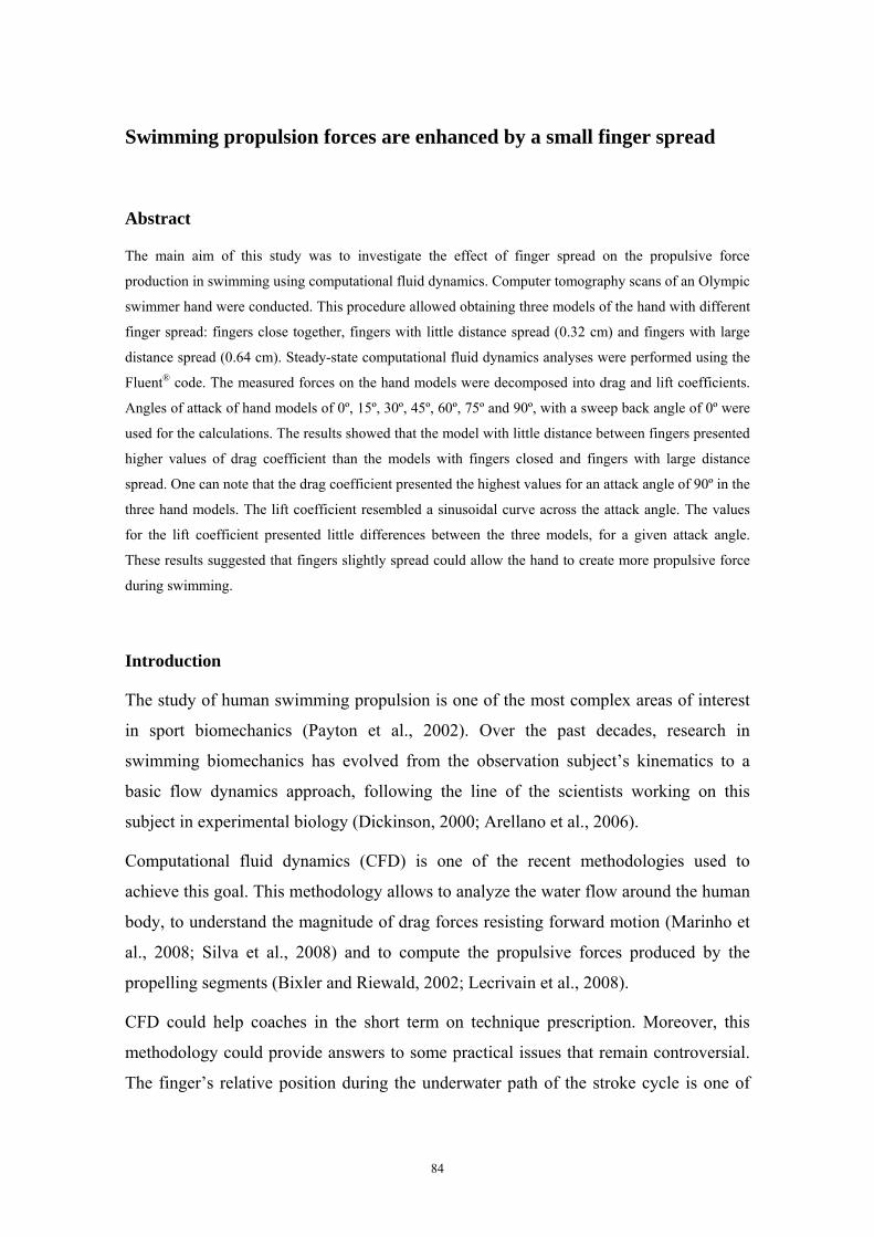
Swimming propulsion forces are enhanced by a small finger spread
Abstract
The main aim of this study was to investigate the effect of finger spread on the propulsive force
production in swimming using computational fluid dynamics. Computer tomography scans of an Olympic
swimmer hand were conducted. This procedure allowed obtaining three models of the hand with different
finger spread: fingers close together, fingers with little distance spread (0.32 cm) and fingers with large
distance spread (0.64 cm). Steady-state computational fluid dynamics analyses were performed using the
Fluent® code. The measured forces on the hand models were decomposed into drag and lift coefficients.
Angles of attack of hand models of 0º, 15º, 30º, 45º, 60º, 75º and 90º, with a sweep back angle of 0º were
used for the calculations. The results showed that the model with little distance between fingers presented
higher values of drag coefficient than the models with fingers closed and fingers with large distance
spread. One can note that the drag coefficient presented the highest values for an attack angle of 90º in the
three hand models. The lift coefficient resembled a sinusoidal curve across the attack angle. The values
for the lift coefficient presented little differences between the three models, for a given attack angle.
These results suggested that fingers slightly spread could allow the hand to create more propulsive force
during swimming.
Introduction
The study of human swimming propulsion is one of the most complex areas of interest
in sport biomechanics (Payton et al., 2002). Over the past decades, research in
swimming biomechanics has evolved from the observation subject’s kinematics to a
basic flow dynamics approach, following the line of the scientists working on this
subject in experimental biology (Dickinson, 2000; Arellano et al., 2006).
Computational fluid dynamics (CFD) is one of the recent methodologies used to
achieve this goal. This methodology allows to analyze the water flow around the human
body, to understand the magnitude of drag forces resisting forward motion (Marinho et
al., 2008; Silva et al., 2008) and to compute the propulsive forces produced by the
propelling segments (Bixler and Riewald, 2002; Lecrivain et al., 2008).
CFD could help coaches in the short term on technique prescription. Moreover, this
methodology could provide answers to some practical issues that remain controversial.
The finger’s relative position during the underwater path of the stroke cycle is one of
84
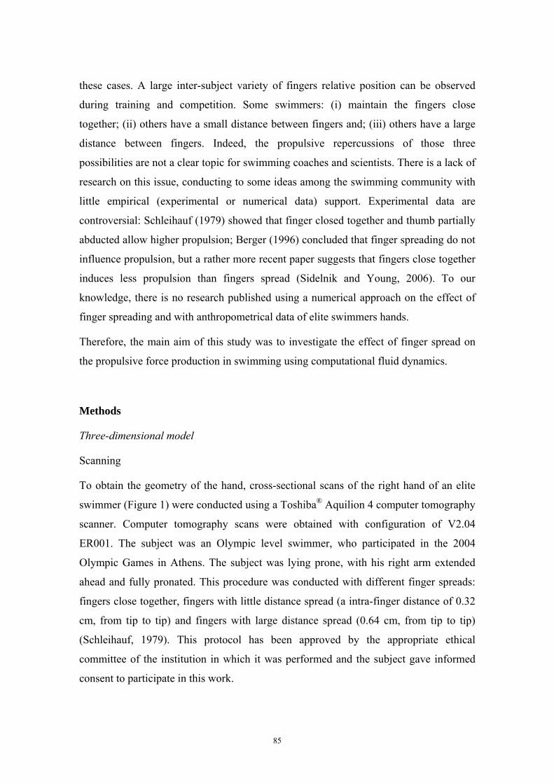
these cases. A large inter-subject variety of fingers relative position can be observed
during training and competition. Some swimmers: (i) maintain the fingers close
together; (ii) others have a small distance between fingers and; (iii) others have a large
distance between fingers. Indeed, the propulsive repercussions of those three
possibilities are not a clear topic for swimming coaches and scientists. There is a lack of
research on this issue, conducting to some ideas among the swimming community with
little empirical (experimental or numerical data) support. Experimental data are
controversial: Schleihauf (1979) showed that finger closed together and thumb partially
abducted allow higher propulsion; Berger (1996) concluded that finger spreading do not
influence propulsion, but a rather more recent paper suggests that fingers close together
induces less propulsion than fingers spread (Sidelnik and Young, 2006). To our
knowledge, there is no research published using a numerical approach on the effect of
finger spreading and with anthropometrical data of elite swimmers hands.
Therefore, the main aim of this study was to investigate the effect of finger spread on
the propulsive force production in swimming using computational fluid dynamics.
Methods
Three-dimensional model
Scanning
To obtain the geometry of the hand, cross-sectional scans of the right hand of an elite
swimmer (Figure 1) were conducted using a Toshiba® Aquilion 4 computer tomography
scanner. Computer tomography scans were obtained with configuration of V2.04
ER001. The subject was an Olympic level swimmer, who participated in the 2004
Olympic Games in Athens. The subject was lying prone, with his right arm extended
ahead and fully pronated. This procedure was conducted with different finger spreads:
fingers close together, fingers with little distance spread (a intra-finger distance of 0.32
cm, from tip to tip) and fingers with large distance spread (0.64 cm, from tip to tip)
(Schleihauf, 1979). This protocol has been approved by the appropriate ethical
committee of the institution in which it was performed and the subject gave informed
consent to participate in this work.
85
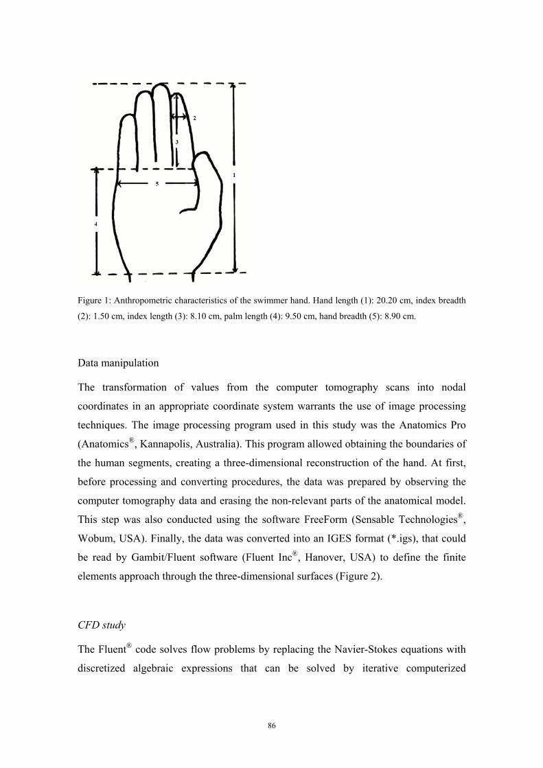
Figure 1: Anthropometric characteristics of the swimmer hand. Hand length (1): 20.20 cm, index breadth
(2): 1.50 cm, index length (3): 8.10 cm, palm length (4): 9.50 cm, hand breadth (5): 8.90 cm.
Data manipulation
The transformation of values from the computer tomography scans into nodal
coordinates in an appropriate coordinate system warrants the use of image processing
techniques. The image processing program used in this study was the Anatomics Pro
(Anatomics®, Kannapolis, Australia). This program allowed obtaining the boundaries of
the human segments, creating a three-dimensional reconstruction of the hand. At first,
before processing and converting procedures, the data was prepared by observing the
computer tomography data and erasing the non-relevant parts of the anatomical model.
This step was also conducted using the software FreeForm (Sensable Technologies®,
Wobum, USA). Finally, the data was converted into an IGES format (*.igs), that could
be read by Gambit/Fluent software (Fluent Inc®, Hanover, USA) to define the finite
elements approach through the three-dimensional surfaces (Figure 2).
CFD study
The Fluent® code solves flow problems by replacing the Navier-Stokes equations with
discretized algebraic expressions that can be solved by iterative computerized
86
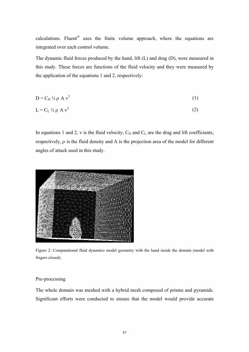
calculations. Fluent® uses the finite volume approach, where the equations are
integrated over each control volume.
The dynamic fluid forces produced by the hand, lift (L) and drag (D), were measured in
this study. These forces are functions of the fluid velocity and they were measured by
the application of the equations 1 and 2, respectively:
D = CD ½ ρ A v2 (1)
L = CL ½ ρ A v2 (2)
In equations 1 and 2, v is the fluid velocity, CD and CL are the drag and lift coefficients,
respectively, ρ is the fluid density and A is the projection area of the model for different
angles of attack used in this study.
Figure 2: Computational fluid dynamics model geometry with the hand inside the domain (model with
fingers closed).
Pre-processing
The whole domain was meshed with a hybrid mesh composed of prisms and pyramids.
Significant efforts were conducted to ensure that the model would provide accurate
87
results by decreasing the grid node separation in areas of high velocity and pressure
gradients.
Solving steady flow
Angles of attack of hand models of 0º, 15º, 30º, 45º, 60º, 75º and 90º, with a sweep back
angle of 0º (thumb as the leading edge) were used for the calculations (Schleihauf,
1979).
Steady-state CFD analyses were performed using the Fluent® code and the drag and lift
coefficients were calculated for a flow velocity of 2.0 m.s-1 (Lauder et al., 2001; Rouboa
et al., 2006).
We used the segregated solver with the standard k-epsilon turbulence model because
this turbulence model was shown to be accurate with measured values in a previous
research (Moreira et al., 2006).
All numerical computational schemes were second-order, which provides a more
accurate solution than first-order schemes. We used a turbulence intensity of 1.0% and a
turbulence scale of 0.10 m. The water temperature was 28º C with a density of 998.2
kg/m3 and a viscosity of 0.001 kg/mm/s. Incompressible flow was assumed. The
measured forces on the hand models were decomposed into drag (CD) and lift (CL)
coefficients, using equations 1 and 2.
Results
Figures 3 and 4 show the values of CD and CL, respectively, obtained for the hand
model with different finger spread.
One can note that the CD presented the highest values for an attack angle of 90º in the
three hand models (≈0.90 < CD < 1.10). In the three models the CD increased with the
attack angle. Moreover, it was possible to observe that for attack angles higher than 30º,
the model with little distance between fingers presented higher values of CD when
compared with the models with fingers closed and with large finger spread. This last
88
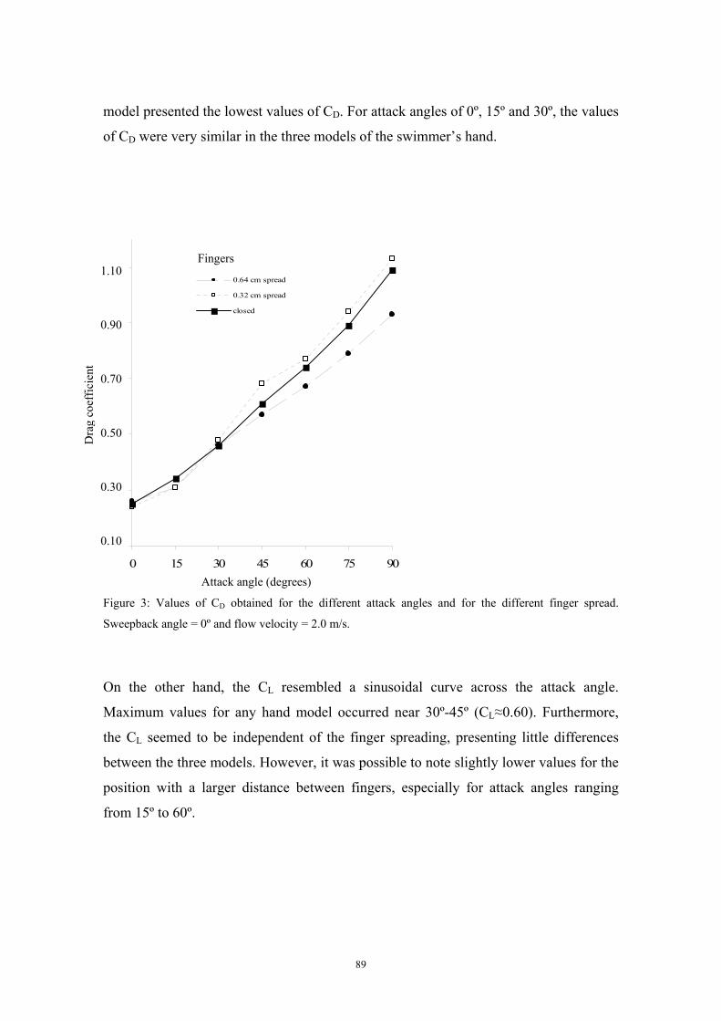
model presented the lowest values of CD. For attack angles of 0º, 15º and 30º, the values
of CD were very similar in the three models of the swimmer’s hand.
0,1
0,3
0,5
0,7
0,9
1,1
0 15 30 45 60 75 90
Fingers
0.64 cm spread
0.32 cm spread
closed
Figure 3: Values of CD obtained for the different attack angles and for the different finger spread.
Sweepback angle = 0º and flow velocity = 2.0 m/s.
On the other hand, the CL resembled a sinusoidal curve across the attack angle.
Maximum values for any hand model occurred near 30º-45º (CL≈0.60). Furthermore,
the CL seemed to be independent of the finger spreading, presenting little differences
between the three models. However, it was possible to note slightly lower values for the
position with a larger distance between fingers, especially for attack angles ranging
from 15º to 60º.
Dra
g co
effic
ient
1.10
0.90
0.70
0.50
0.30
0.10
Attack angle (degrees)
89
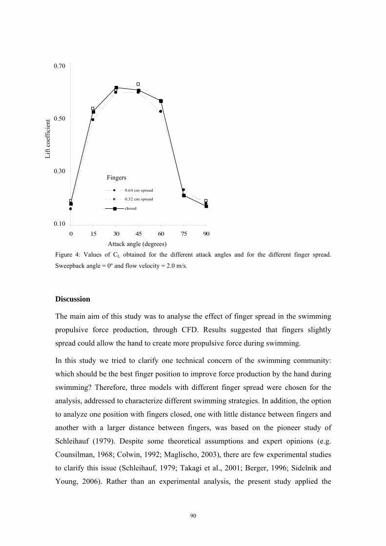
0,1
3
5
7
0 15 30 45 60 75 90
0,
0,
0,
0.64 cm spread
0.32 cm spread
closed
Figure 4: Values of CL obtained for the different attack angles and for the different finger spread.
Sweepback angle = 0º and flow velocity = 2.0 m/s.
Discussion
The main aim of this study was to analyse the effect of finger spread in the swimming
propulsive force production, through CFD. Results suggested that fingers slightly
spread could allow the hand to create more propulsive force during swimming.
In this study we tried to clarify one technical concern of the swimming community:
which should be the best finger position to improve force production by the hand during
swimming? Therefore, three models with different finger spread were chosen for the
analysis, addressed to characterize different swimming strategies. In addition, the option
to analyze one position with fingers closed, one with little distance between fingers and
another with a larger distance between fingers, was based on the pioneer study of
Schleihauf (1979). Despite some theoretical assumptions and expert opinions (e.g.
Counsilman, 1968; Colwin, 1992; Maglischo, 2003), there are few experimental studies
to clarify this issue (Schleihauf, 1979; Takagi et al., 2001; Berger, 1996; Sidelnik and
Young, 2006). Rather than an experimental analysis, the present study applied the
Fingers
Attack angle (degrees)
Lift
coef
ficie
nt
0.70
0.50
0.30
0.10
90
numerical techniques of CFD to compute the forces produced by the model of the
swimmer’s hand. Bixler et al. (2007) has already demonstrated the validity of CFD
analysis as a tool to examine the water flow around the swimmer body. Nevertheless, it
is very important that the digital model corresponds to a truthful representation of the
human segment to ensure accurate numerical results (Candalai and Reddy, 1992;
Lecrivain et al., 2008). Indeed, the computer tomography scans allowed the creation of
a true digital model of the swimmer’s hand (Aritan et al., 1997). Moreover, precise
images of complex three-dimensional shape bodies, as human hand’s, obtained by
imagiography is becoming widely used in reverse engineering (Lecrivain et al., 2008).
The main finding of the present research was that the model with little distance between
fingers presented higher values of CD than the models with fingers close together and
with fingers widely spread. Furthermore, the CL seemed to be independent of the finger
spread, presenting little differences between the three models. These results suggest that
the use of a position with little distance between fingers seems to be gainful for
swimmers.
The hand position with little distance between fingers seemed to increase the projection
area of the hand, thus increasing force production. The distance between fingers seemed
not enough to allow the water to flow freely. Indeed, a turbulent flow between the
fingers may be formed, creating some kind of barrier. Nevertheless, regarding the CL,
the values for the position with little finger spread and for the position with fingers
closed were very similar. For attack angles lower than 90º, the flow above the dorsal
surface of the hand, flowing at high velocities, could prevent the flow between fingers.
In this condition, assuming the higher velocity difference between the two surfaces of
the swimmers’ hand will occur at the attack angle corresponding to the higher CL (in
this case, between 30º and 45º), it will be expectable, then, that the so called “barrier”
will be stronger at that CL values. As it can be seen from the figures 3 and 4, at an attack
angle of 45º it is perceptible a relative grow of the CD value considering the curve
tendency, corresponding to the maximal CL value obtained for the slight spreading
condition, and for all studied conditions, which is, for the higher flow velocity
difference between both faces of the hand. Concerning this topic, Ungerechts and
Klauck (2006) did suggest fingers slightly spread to induce flow around the hand at the
beginning of the arm cycle.
91
However, this gain did not occur when we analyzed larger distances between fingers. In
both CD and CL coefficients, for the position with large finger spread, the values were
lower when compared to the positions with fingers closed and slightly spread. For the
CD and for attack angles higher than 30º, the position with more distance between
fingers presented lower values. This position presented also lower values in CL. It seems
that there is a critical distance between fingers beyond which the force production
became compromised.
Schleihauf (1979) has already reported an identical situation. The CD for both fingers
closed and slightly spread positions presented higher values than the large spread
position. On the other hand, the values of CL increased in indirect proportion to finger
spread for attack angles ranging between 0º and 60º. Berger (1996) reported that
spreading the finger did not influence propulsive force. Moreover, lift force at attack
angles between 60º-80º was higher when spreading the fingers (Berger, 1996). In a
recent experimental study, Sidelnik and Young (2006) determined that a hand with 10º
of separation between fingers created more stroke force than a fingers-together
configuration, across all attack angles tested.
Furthermore, CD presented the highest values for an attack angle of 90º in the three hand
models (≈0.90<CD<1.10) whereas CL resembled a sinusoidal curve across the attack
angle (CL≈0.60). These results are quite similar to the ones already described with
experimental methodologies (e.g., Schleihauf, 1979; Berger et al., 1995; Takagi et al.,
2001).
In summary, this study showed that CFD methodology can be an important tool for
coaches and swimmers to improve performance. However, the present results were
obtained using steady flow simulations. Further studies should include the unsteady
effects of motion, such as accelerations, decelerations and rotations (Sanders, 1999). It
seems interesting to observe if the results would be the same as suggested by
Ungerechts and Klauck (2006). These authors proposed the use of fingers slightly
spread to induce flow around the hand at the beginning of the arm cycle and to create
unsteady flow to allow a marked increase of propelling momentum.
Although the results of the present numerical research showed that fingers slightly
spread created more force, this is a comparison of only three hand positions. In the
92
future, there are many hand shape parameters that could be included by varying for
instance wrist angle, thumb abduction and hand configuration (flat vs. cupped palm and
flexed vs. extended interphalangeal joints).
References
Arellano, R., Nicoli-Terrés, J.M., Redondo, J.M. (2006). Fundamental hydrodynamics of swimming
propulsion. Portuguese Journal of Sport Sciences, 6(Suppl. 2), 15-20.
Aritan, S., Dabnichki, P., Bartlett, R. (1997). Program for generation of three-dimensional finite element
mesh form magnetic resonance imaging scans of human limbs. Medical Engineering and Physics,
19, 681-689.
Berger, M. (1996). Force generation and efficiency in front crawl swimming. PhD Thesis. Amsterdam:
Faculty of Human Movement Sciences, Vrije Universiteit.
Berger, M., de Groot, G., Hollander, A.P. (1995). Hydrodynamic drag and lift forces on human/arm
models. Journal of Biomechanics, 28, 125-133
Bixler, B.S., Riewald, S. (2002). Analysis of swimmer’s hand and arm in steady flow conditions using
computational fluid dynamics. Journal of Biomechanics, 35, 713-717.
Bixler, B., Pease, D., Fairhurst, F. (2007). The accuracy of computational fluid dynamics analysis of the
passive drag of a male swimmer. Sports Biomechanics, 6, 81-98.
Candalai, R.S., Reddy, N.P. (1992). Stress distribution in a physical buttock model: effect of simulated
bone geometry. Journal of Biomechanics, 15, 493-504.
Colwin, C. (1992). Swimming into the 21th Century. Champaign, Illinois: Leisure Press.
Counsilman, J. (1968). The Science of Swimming. Englewood Cliffs: Prenctice-Hall Inc.
Dickinson, M.H. (2000). How animals move: an integrative view. Science, 288, 100-106.
Lauder, M., Dabnichki, P., Bartlett, R. (2001). Improved accuracy and reliability of sweepback angle,
pitch angle and hand velocity calculations in swimming. Journal of Biomechanics, 34, 31-39.
Lecrivain, G., Slaouti, A., Payton, C., Kennedy, I. (2008). Using reverse engineering and computational
fluid dynamics to investigate a lower arm amputee swimmer’s performance. Journal of
Biomechanics, 41, 2855-2859.
Maglischo, E.W. (2003). Swimming Fastest. The essential reference on training, technique and program
design. Champaign, Illinois: Human Kinetics.
Marinho, D.A., Reis, V.M., Alves, F.B., Vilas-Boas, J.P., Machado, L., Silva, A.J., Rouboa, A.I. (2008).
The hydrodynamic drag during gliding in swimming. Journal of Applied Biomechanics (in press).
93
Moreira, A., Rouboa, A., Silva, A., Sousa, L., Marinho, D., Alves, F., Reis, V., Vilas-Boas, J.P., Carneiro,
A., Machado, L. (2006). Computational analysis of the turbulent flow around a cylinder.
Portuguese Journal of Sport Sciences, 6(Suppl. 1), 105.
Payton, C., Baltzopoulos, V., Bartlett, R. (2002). Contributions of rotations of the trunk and upper
extremity to hand velocity during front crawl swimming. Journal of Applied Biomechanics, 18,
243.
Rouboa, A., Silva, A., Leal, L., Rocha, J., Alves, F. (2006). The effect of swimmer’s hand/forearm
acceleration on propulsive forces generation using computational fluid dynamics. Journal of
Biomechanics, 39, 1239-1248.
Sanders, R.H. (1999). Hydrodynamic characteristics of a swimmer’s hand. Journal of Applied
Biomechanics, 15, 3-26.
Schleihauf, R.E. (1979). A hydrodynamic analysis of swimming propulsion. In: J. Terauds, E.W.
Bedingfield (Eds.), Swimming III, pp. 70-109. Baltimore: University Park Press.
Sidelnik, N.O., Young, B.W. (2006). Optimising the freestyle swimming stroke: the effect of finger
spread. Sports Engineering, 9, 129-135.
Silva, A.J., Rouboa, A., Moreira, A., Reis, V., Alves, F., Vilas-Boas, J.P., Marinho, D. (2008). Analysis
of drafting effects in swimming using computational fluid dynamics. Journal of Sports Science
and Medicine, 7(1), 60-66.
Takagi, H., Shimizu, Y., Kurashima, A., Sanders, R. (2001). Effect of thumb abduction and adduction on
hydrodynamic characteristics of a model of the human hand. In: J. Blackwell, R. Sanders (Eds.),
Proceedings of Swim Sessions of the XIX International Symposium on Biomechanics in Sports, pp.
122-126. San Francisco: University of San Francisco.
Ungerechts, B., Klauck, J. (2006). Consequences of unsteady flow effects for functional attribution of
swimming strokes. Portuguese Journal of Sport Sciences, 6(Suppl. 2), 109-111.
94
Review
Swimming simulation: a new tool for swimming research and practical
applications
Marinho, D.A., Barbosa, T.M., Kjendlie, P.L., Vilas-Boas, J.P., Alves, F.B., Rouboa, A.I., Silva, A.J.
(2009). Swimming simulation: a new tool for swimming research and practical applications. In: M. Peters
(Ed.), Lecture Notes in Computational Science and Engineering – CFD and Sport Sciences. Berlin:
Springer (in press).
95
Swimming simulation: a new tool for swimming research and practical
implications
Abstract
This chapter covers topics in swimming simulation from a computational fluid dynamics perspective.
This perspective means emphasis on the fluid mechanics and CFD methodology applied in swimming
research. We concentrated on numerical simulation results, considering the scientific simulation point-of-
view and especially the practical implications with swimmers.
1. Introduction
Swimming is one of the major athletic sports and many efforts are being made to
establish new records in all events. To swim faster, thrust should be maximized and
drag should be minimized. These aims are difficult to achieve because swimmers surge,
heave, roll and pitch during every stroke cycle. In addition, measurements of human
forces and mechanical power are difficult due to the restrictions of measuring devices
and the specificity of aquatic environment. Thus, human swimming evaluation is one of
the most complex but outstanding and interesting topics in sport biomechanics. Over the
past decades, research in swimming biomechanics has evolved from the study of
swimmer’s kinematics to a flow dynamics approach, following the line of research from
the experimental biology (Dickinson, 2000; Arellano et al., 2006). Significant efforts
have been made to understand swimming mechanics on a deeper basis. In the past, most
of the studied involved experimental data, nowadays the numerical solutions can give
new insights about swimming science. Computational fluid dynamics (CFD)
methodology is one of the different methods that have been applied in swimming
research to observe and understand water movements around the human body and its
application to improve swimming technique and/or swimming equipments and
therefore, swimming performance. One recent example is the cooperation between
Speedo® swimwear manufacturer and Fluent® CFD software provider, in the process of
improving the swimwear’s hydrodynamic characteristics. The CFD software was
incorporated into Speedo’s design process to evaluate the drag and fluid flow
characteristics around the male and female swimmers for various flow conditions. This
96
work allowed Speedo® to simulate the flow around the virtual swimmer body, thus
making the swimsuits as hydrodynamic as possible (Fluent, 2004). Fastskin FSII® and
recently the LZR® suits are the most visible examples of the application of CFD in
swimming research and its influence in the swimming performance. However, other
issues related to swimming science, besides the swimwear, were and are also being
solved with this methodology.
Therefore, the use of CFD can be considered as a new step forward to the understanding
of swimming mechanisms and seems to be an interesting approach to the swimming
research. In this sense, the main purpose of this book chapter is to present the basis of
this methodology and its applications in swimming research.
This chapter is divided in seven parts. In the first part, we introduce the issue and the
main aims of the paper. In the second, we briefly explain the CFD methodology and its
basic steps. In the third part, we show some applications of CFD in biological systems.
In the fourth part, some applications of CFD to human beings are presented. In the fifth
part, it can be observed the contribution of the different studies in swimming using
CFD, where we can analyse some practical application of the CFD technology in
swimming research. In the final parts, we present some ideas to future studies in
swimming using CFD and the main conclusions.
2. Fluid mechanics and CFD methodology
2.1. Background
CFD is a branch of fluid mechanics that solves and analyses problems involving a fluid
flow by means of computer-based simulations. CFD methodology consists of a
mathematical model that replaces the Navier-Stokes equations with discretized
algebraic expressions that can be solved by iterative computerized calculations. The
Navier–Stokes equations describe the motion of viscous non-compressible fluid
substances. These equations arise from applying Newton's second law to fluid motion,
together with the assumption that the fluid stress is the sum of a diffusing viscous term
(proportional to the gradient of velocity), plus a pressure term. A solution of the
Navier–Stokes equations is called a velocity field or flow field, which is a description of
the velocity of the fluid at a given point in space and time. CFD methodology is based
97
on the finite volume approach. In this approach the equations are integrated over each
control volume. It is required to discretize the spatial domain into small cells to form a
volume mesh or grid, and then apply a suitable algorithm to solve the equations of
motion. In addition, CFD analyses complements testing and experimentation, reducing
the total effort required in the experimental design and data acquisition.
In the beginning of its application CFD was quite difficult to use. It was applied only in
a few companies of high technological level, namely in the Aerospatiale Engineering or
in some specific scientific research areas. It became obvious that its application had to
assume a user friendly interface and to progress from a heavy and difficult computation
to practical, flexible, intuitive and quick software. Therefore, the following step was to
transform CFD in a new set of commercial software to be used in different applications
and to help the connection between the user and the computer.
Presently, this tool is used in the resolution of complex engineering problems involving
fluid dynamics and it is also being extended to the study of complex flow regimes that
define the forces generated by species in self propulsion.
The basic steps of CFD analysis are:
1. Problem identification and pre-processing: (i) define the modelling goals, (ii) identify
the domain that wants to model, (iii) design and create the grid.
2. Solver execution: (i) set up the numerical model, (ii) compute and monitor the
solution.
3. Post-Processing: (i) examine the results; (ii) consider revisions to the model.
2.2. Advantages and limitations
CFD can be used to predict fluid flow, heat and mass transfer, chemical reactions and
related phenomena by solving the set of governing mathematical equations. The results
of CFD analyses can be relevant in conceptual studies of new designs, detailed product
development, troubleshooting and redesign.
Lyttle and Keys (2006) referred that CFD can provide the answers into many complex
problems which have been unobtainable using physical testing techniques. One of the
98
major benefits is to quickly answer many “what if” type questions. It is possible to test
many variations until one arrives at an optimal result, without physical/experimental
testing. CFD could be seen as bridging the gap between theoretical and experimental
fluid dynamics. For example, with this methodology it is possible to study the
aerodynamic of a race car before being constructed or to study the air flow inside the
ventilation system of a park station, to simulate situations where a fire takes place, to
analyse the ventilation and the acclimatisation of a specific building, such as an hospital
where the quality of the air is quite important.
CFD was developed to model any flow filed provided the geometry of the object is
known and some initial flow conditions are prescribed. CFD is based on the use of
computers to solve mathematical equation systems. However, it is essential to apply the
specific data to characterize the study conditions. Therefore, in the CFD studies the
subject who analyzes the problem must be considered. The scientific knowledge, the
computational program which solves the equations system representing the problem, the
kind of computer that executes the defined calculations in the numerical program and
the person who verifies and analyses the obtained results must also be taken in account.
In this sense, one must consider that the CFD analyses can have some inaccurate results
if there is not thorough study of the specific situation. The inserted data should not have
wide-ranging estimation. On the other hand, the available computational resources can
be insufficient to obtain results with the necessary precision. Previous to any simulation,
the flow situation must be very well analysed and understood, as well as of the obtained
results.
2.3. Validity, reliability, accuracy
CFD studies are becoming more and more popular. However, a main concern still
persists. Can the numerical data be comparable with experimental research? Are the
numerical results accurate enough to be meaningful and therefore have ecological
validity? For sport scientists who work in close connection with coaches and athletes
this question is important in order to give good, appropriate and individual feed-backs
for practitioners.
99
Several studies within different scopes attempted to verify the validity and accuracy of
CFD. This numerical tool has been validated as being feasible in modelling complicated
biological fluid dynamics, through a series of stepwise baseline benchmark tests and
applications for realistic modelling of different scopes for hydro and aerodynamics of
locomotion (Liu, 2002).
In bioscience, Yim et al. (2005) described in detail critical aspects of this methodology
including surface reconstruction, construction of the volumetric mesh, imposition of
boundary conditions and solution of the finite element model. Yim et al. (2005) showed
the validity of the methodology in vitro and in vivo for experimental biology. Barsky et
al. (2004) have also demonstrated good agreement between the numerical and
experimental data on tethered DNA in flow. Moreover, Gage et al. (2002) reported that
computational techniques coupled with experimental verification can offer insight into
model validity and showed promise for the development of accurate three-dimensional
simulations of medical procedures.
In engineering, Venetsanos et al. (2003) illustrated an application of CFD methods for
the simulation of an actual hydrogen explosion occurred in a built up area of central
Stockholm Sweden in 1983. The subsequent simulation of the combustion adopted
initial conditions for mean flow and turbulence from the dispersion simulations, and
calculated the development of a fireball. This data provided physical values that were
used as a comparison with the known accident details to give an indication of the
validity of the models. The simulation results were consistent with both the reported
near-field damage to buildings and persons and with the far-field damage to windows.
In sports some trials have been carried-out to compare the numerical results with
experimental results also. A combined CFD and experimental study on the influence of
the crew position on the bobsleigh aerodynamics was conducted by Dabnichki and
Avital (2006). The experimental results obtained in a wind tunnel suggested that the
adopted computational method is appropriate and yields valid results. In what concerns
to aquatic sports there is a lack of studies comparing experimental and CFD data.
However, CFD was developed to be valid and accurate in a large scope of fluid
environments, bodies and tasks, including sports. So, it is assumed that CFD have
ecological validity even for swimming research.
100
Another important concern is related with CFD reliability. In experimental tests, the
input data are not always the same and thus the outputs will vary. However, the
numerical simulations allow having always the same input conditions and therefore the
same outputs.
2.4. Areas of application
CFD has a wide field of applications, being used in biomechanical studies applied to
several research fields, such as industry, biology, medicine and sports (e.g. Boulding et
al., 2002; Marshall et al., 2004; Dabnichki and Avital, 2006; Guerra et al., 2007).
The broad physical modelling capabilities of CFD have been applied to industrial
applications ranging from air flow over an aircraft wing to combustion in a furnace,
from bubble columns to glass production, from blood flow to semiconductor
manufacturing, from clean room design to wastewater treatment plants. The ability of
the software to model in-cylinder engines, aeroacoustics, turbomachinery, and
multiphase systems has served to broaden its reach. Today, thousands of companies
throughout the world benefit from this important engineering design and analysis tool.
Its extensive range of multiphysics capabilities makes it an important and interesting
tool in engineering studies.
Recently, medical applications were also described by this method (e.g. Berthier et al.,
2002; Ruiz et al., 2005). Berthier et al. (2002) analyzed the blood flow patterns in a
coronary vessel digital model whereas Ruiz et al. (2005) simulated the complex three-
dimensional airflow pattern in the human nasal passageways.
In biology, the CFD models started to be used in the middle of the 90s in the flying
study of insects as well as in the inquiring of the aerodynamic and hydrodynamic forces
involved in the propulsion and energy conservation through the generation of organized
vortex systems in animals displacing by body undulation (Liu et al., 1996; Liu et al.,
1997; Liu et al., 1998).
In sports scope, the main results suggested that a CFD analysis could provide useful
information about performance. Indeed, this methodology has produced significant
improvements in equipment design and technique prescription in areas such as sailing
101
performance (Pallis et al., 2000), Formula 1 racing (Kellar et al., 1999) and winter
sports (Dabnichki and Avital, 2006). CFD has been applied to swimming in order to
understand its relationships with performance mainly by three research groups. One
coordinated by Barry Bixler from Honeywell Aerospace (USA), another coordinated by
António José Silva from the Research Centre in Sport, Health and Human Development
(Portugal), and another coordinated by Bruce Mason from the Australian Institute of
Sport (Australia).
The numerical techniques have been applied to the analysis of the propulsive forces
generated by the propelling segments (Bixler and Schloder, 1996; Rouboa et al., 2006)
and to the analysis of the hydrodynamic drag forces resisting forward motion (Lyttle
and Keys, 2006; Marinho et al., 2008a).
3. CFD applied to biological systems
Fluid dynamic phenomena in animal locomotion are complicated because biological
fluid dynamics involves the interaction of elastic or even flexible living issues with
surrounding viscous fluid (Liu, 2002). The biological fluid dynamic phenomena are, in
general, characterized by large-scale vortex structure due to the highly unsteady motions
and the complex and variable geometry of the object in swimming and flying.
3.1. CFD overview in birds/insects
The flight of insects has fascinated physicists and biologists for many years. On one
hand, insects owe much of their amazing evolutionary success to flight. One the other,
their flight seems improbable using standard aerodynamic theory (Sane, 2003). The
small size, high stroke frequency and peculiar reciprocal flapping motion of insects
have combined to prevent simple explanations of flight aerodynamics. Nevertheless,
recent developments in high-speed videography and tools for computational and
mechanical modelling have allowed researchers to make progresses in the
understanding of insect flight. These CFD models, combined with modern flow
visualization techniques, have revealed that the fluid dynamic phenomena underlying
flapping flight are different from those of non-flapping, two-dimensional wings on
102
which most models are based (Sane, 2003). In fact, even at high angles of attack, a
prominent leading edge vortex remains stably attached on the insect wing and does not
shed into an unsteady wake thus enhances the forces generated by the wing, enabling
insects to hover and maneuver.
With recent advances in computational methods, many researchers have begun
exploring numerical methods to resolve the insect flight problem (Ellington et al., 1996;
Liu and Kawachi, 1998; Liu et al., 1998; Dickinson et al., 1999; Wang, 2000; Hamdani
and Sun, 2001). Although ultimately these techniques are more rigorous than simplified
analytical solutions, they require large computational resources and are not as easily
applied to large comparative data sets (Sane, 2003). Moreover, CFD simulations rely
critically on empirical data both for validation and relevant kinematic input. However,
several studies have recently emerged that have led to some important CFD models of
insect flight.
Liu and co-workers (Liu and Kawachi, 1998; Liu et al., 1998) using the hawkmoth
Manduca as a model, were the first to attempt a full Navier-Stokes simulation by a
finite volume approach. In addition to confirm the smoke streak patterns observed on
both real and dynamically scaled model insects (Ellington et al., 1996), this study added
finer detail to the flow structure and predicted the time course of the aerodynamic forces
resulting from these flow patterns. Furthermore, Dickinson et al. (1999) used a
computational approach to model Drosophila Melanogaster flight for which force
records exist based on a dynamically scaled model. Although roughly matching
experimental results, these methods have added a wealth of qualitative detail to the
empirical measurements (Ramamurti and Sandberg, 2002), and even provided
alternative explanations for experimental results (Sun and Tang, 2002). Despite the
importance of considering the three-dimensional effects, comparisons of experiments
and simulations in two-dimensions have also provided important insight. For instance,
the simulations of Hamdani and Sun (2001) matched complex features of prior
experimental results with two-dimensional airflows at low Reynolds number (Dickinson
and Gotz, 1993). In fact, two-dimensional CFD models have also been used to address
feasibility issues (Sane, 2003). Wang (2000) reported that the force dynamics of two-
dimensional wings, although not stabilized by three-dimensional effects, might still be
sufficient to explain the enhanced lift coefficient measured in insects.
103
Interestingly some swimming researchers suggest a link between swimmers propulsion
actions and insects or birds wings actions (Colwin, 1984; Toussaint et al., 2002).
Colwin (1984) firstly introduced the concept of propulsion through vortex generation in
human swimming, based upon the mechanism of flapping wings fly, and Toussaint et
al. (2002) suggested that, as insects and birds wing’s do, swimmers also use arm
rotation that could lead to the establishment of a proximal-distal pressure gradient,
which would induce significant axial flow along the arm toward the hand. It was
observed that: (i) the flow during insweep and part of the outsweep was highly
unsteady; (ii) the arm movements were largely rotational; (iii) a clear axial flow
component, not in the direction of the arm movement, was observed during insweep and
outsweep and; (iv) both the V-shaped "contracting" arrangement of the tufts during the
outsweep, and pressure recordings, point to a pressure gradient along the direction of
the arm during the outsweep, as predicted on theoretical grounds (Toussaint et al.,
2002).
3.2. CFD overview in fishes
Most aquatic animals use the jet-stream propulsion in a form of propagating a transverse
wave along the body from head to tail (Liu, 2002). Physics of fluids around fishes
swimming is often of a dynamic vortex structure as their fins usually perform
periodically oscillating motions.
Liu et al. (1996) studied the hydrodynamics and undulating propulsion of tadpoles using
a two-dimensional CFD modelling method. The CFD analysis showed that the
kinematics of tadpoles is specifically matched to their special shape and produces a jet-
stream propulsion with high propulsive efficiency, as high as that achieved by teleost
fishes. The authors reported as well that the shapes and kinematics of tadpoles appeared
to be specially adapted to the requirement of these organisms to transform into frogs.
Liu et al. (1997) extended their two-dimensional modelling of tadpole swimming to
more realistic three-dimensional situation. Essentially they asked how the three-
dimensional effects of unsteady undulatory hydrodynamics by swimming tadpoles
affected their locomotion performance. Within this study the unsteady flow generated
by an undulating vertebrate has been modelled in three dimensions for the first time.
104
This study demonstrated the feasibility of using three-dimensional CFD methods to
model the locomotion of undulatory organisms. Tadpoles are unusual among vertebrates
in having a globose body with a laterally compressed tail abruptly appended to it.
Compared with most teleost fishes, tadpoles swim awkwardly, with waves of relatively
high amplitude at both the snout and tail tip. The authors confirmed results from the
previous two-dimensional study, which suggested that the characteristic shape of
tadpoles was closely matched to their unusual kinematics. Specifically, the three-
dimensional results revealed that the shape and kinematics of tadpoles collectively
produce a small 'dead water' zone between the head-body and tail during swimming
precisely where tadpoles can and do grow hind limbs without those limbs obstructing
flow. In addition, Liu et al. (1997) showed that three-dimensional hydrodynamic effects
(cross flows) were largely constrained to a small region along the edge of the tail fin.
Although this three-dimensional study confirmed most of the results of the two-
dimensional study, it showed that propulsive efficiency for tadpoles was lower than
predicted from a two-dimensional analysis. This low efficiency was not, however, a
result of the high-amplitude undulations of the tadpole. This was demonstrated by
forcing the 'virtual' tadpole to swim with fish-like kinematics, i.e. with lower-amplitude
propulsive waves. That particular simulation yielded a much lower efficiency,
confirming that the large-amplitude lateral oscillations of the tadpole provide positive
thrust.
Fishes CFD data, as reported for the insects and birds condition, can give in a near
future some insights or raise questions about propulsive and drag phenomena during
non-steady flow with human locomotion in aquatic environment. Especially topics such
as the undulatory motion and its relationship with human body undulatory motion in
some swim strokes, such as Butterfly stroke, as well as to the kick action in Front
Crawl, Backstroke and Butterfly stroke.
4. CFD applied to human beings
4.1. Terrestrial locomotion
In the literature there are not many works that applied CFD to human terrestrial
locomotion. However, CFD has been recently used in high-performance sports, such as
105
car racing and motorcycling (Hannah, 2002). One of the reasons for the relatively slow
start of the application of CFD in this scope is the enormous complexity of the flow
conditions – non-stationary flows, high level of turbulence and complex body shapes,
requiring the use of very powerful computational facilities and advanced CFD codes
(Dabnichki and Avital, 2006).
Dabnichki and Avital (2006) focused on the influence of the position of crew members
on aerodynamics performance of two-man bobsleigh. The authors studied female crews
because they used sleds built for males and thus there is a bigger gap between the crew
and the side walls. The position of the brakewoman’s body in terms of upper body
inclination and the distance between the cavity and the athlete were studied through
computational means. Dabnichki and Avital (2006) showed that crew members did
influence the drag level significantly and suggested that internal modifications can be
introduced to reduce the overall resistance drag.
Nevertheless, some experience and background knowledge of human terrestrial
locomotion can be useful in a near future for aquatic locomotion. In both environments,
powerful computational facilities and advanced CFD codes will be useful for a better
understanding of human locomotion for a wide variety of tasks.
4.2. Aquatic locomotion
Regarding aquatic locomotion, CFD has been applied in swimming attempting to
understand deeply the biomechanical basis underlying swimming locomotion. Several
studies have been conducted willing to analyze the propulsive forces produced by the
propelling segments (e.g. Bixler and Riewald, 2002; Rouboa et al., 2006) and the drag
force resisting forward motion (e.g. Bixler et al., 2007; Marinho et al., 2008a). To our
knowledge, the application of CFD methodology in aquatic and nautical activities is
restricted to swimming. However, it would be interesting to apply this methodology in
other fields such sailing, windsurfing, surfing, canoeing and rowing, not only in the
analysis of equipment design (Pallis et al., 2000) but also to relate different displacing
strategies with performance. In the same way, CFD can also provide new highlights
about aquatic activities related to health (e.g. head-out aquatic exercises or water-
aerobics) and muscle-skeletal injuries rehabilitation in water (e.g., hydrotherapy).
106
In the following chapter, the application of CFD into competitive swimming will be
discussed deeply.
5. CFD applied to competitive swimming
5.1. Experimental vs. numerical data
CFD analysis in swimming has addressed to understand two main topics of interest: (i)
the propulsive force generated by the propelling segments and; (ii) the drag forces
resisting forward motion, since the interaction between both forces will influence the
swimmer’s speed.
Some authors attempted to compare the numerical data with experimental data available
in previous researches about propulsion and drag. However, not always this is an easy
goal because the models included in the CFD simulations are not the same as used in
experimental measurements.
Bixler et al. (2007) tried to overcome this problem and studied the accuracy of CFD
analysis of the passive drag of a male swimmer. The aim of this study was to build an
accurate computer-based model to study the water flow and drag force characteristics
around and acting on the human body while in a submerged streamlined position.
Comparisons of total drag force were performed between a real swimmer, a digital CFD
model of this same swimmer and a real mannequin based on the digital model. Drag
forces were determined for velocities representative of the ones presented in elite
competition during the underwater gliding (i.e., between 1.50 and 2.25 m/s). Bixler et
al. (2007) found drag forces determined from the digital model using the CFD approach
to be within 4% of the values assessed experimentally for the mannequin, although the
mannequin drag was found to be 18% less than the real swimmer drag (Figure 1). In
fact, the Bixler et al. (2007) study has reinforced the idea of the validity and accuracy of
CFD in swimming research. This study also showed that the drag of the real swimmer is
quite high compared to the model due to little body movements during the gliding
position. Another difference between the swimmer and the model is that the swimmer’s
skin is flexible while the mannequin’s skin is rigid.
107
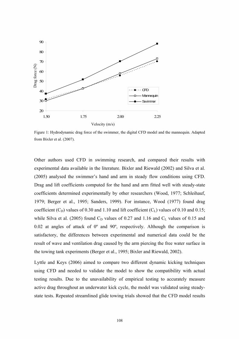
20
30
40
50
60
70
80
90
1.50 1.75 2.00 2.25
CFD
Mannequin
Swimmer
Dra
g fo
rce
(N)
Velocity (m/s)
Figure 1: Hydrodynamic drag force of the swimmer, the digital CFD model and the mannequin. Adapted
from Bixler et al. (2007).
Other authors used CFD in swimming research, and compared their results with
experimental data available in the literature. Bixler and Riewald (2002) and Silva et al.
(2005) analysed the swimmer’s hand and arm in steady flow conditions using CFD.
Drag and lift coefficients computed for the hand and arm fitted well with steady-state
coefficients determined experimentally by other researchers (Wood, 1977; Schleihauf,
1979; Berger et al., 1995; Sanders, 1999). For instance, Wood (1977) found drag
coefficient (CD) values of 0.30 and 1.10 and lift coefficient (CL) values of 0.10 and 0.15;
while Silva et al. (2005) found CD values of 0.27 and 1.16 and CL values of 0.15 and
0.02 at angles of attack of 0º and 90º, respectively. Although the comparison is
satisfactory, the differences between experimental and numerical data could be the
result of wave and ventilation drag caused by the arm piercing the free water surface in
the towing tank experiments (Berger et al., 1995; Bixler and Riewald, 2002).
Lyttle and Keys (2006) aimed to compare two different dynamic kicking techniques
using CFD and needed to validate the model to show the compatibility with actual
testing results. Due to the unavailability of empirical testing to accurately measure
active drag throughout an underwater kick cycle, the model was validated using steady-
state tests. Repeated streamlined glide towing trials showed that the CFD model results
108
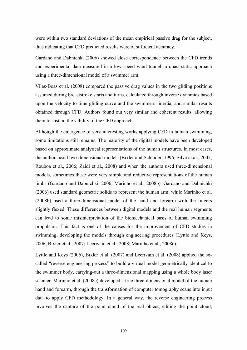
were within two standard deviations of the mean empirical passive drag for the subject,
thus indicating that CFD predicted results were of sufficient accuracy.
Gardano and Dabnichki (2006) showed close correspondence between the CFD trends
and experimental data measured in a low speed wind tunnel in quasi-static approach
using a three-dimensional model of a swimmer arm.
Vilas-Boas et al. (2008) compared the passive drag values in the two gliding positions
assumed during breaststroke starts and turns, calculated through inverse dynamics based
upon the velocity to time gliding curve and the swimmers’ inertia, and similar results
obtained through CFD. Authors found out very similar and coherent results, allowing
them to sustain the validity of the CFD approach.
Although the emergence of very interesting works applying CFD in human swimming,
some limitations still remains. The majority of the digital models have been developed
based on approximate analytical representations of the human structures. In most cases,
the authors used two-dimensional models (Bixler and Schloder, 1996; Silva et al., 2005;
Rouboa et al., 2006; Zaidi et al., 2008) and when the authors used three-dimensional
models, sometimes these were very simple and reductive representations of the human
limbs (Gardano and Dabnichki, 2006; Marinho et al., 2008b). Gardano and Dabnichki
(2006) used standard geometric solids to represent the human arm; while Marinho et al.
(2008b) used a three-dimensional model of the hand and forearm with the fingers
slightly flexed. These differences between digital models and the real human segments
can lead to some misinterpretation of the biomechanical basis of human swimming
propulsion. This fact is one of the causes for the improvement of CFD studies in
swimming, developing the models through engineering procedures (Lyttle and Keys,
2006; Bixler et al., 2007; Lecrivain et al., 2008; Marinho et al., 2008c).
Lyttle and Keys (2006), Bixler et al. (2007) and Lecrivain et al. (2008) applied the so-
called “reverse engineering process” to build a virtual model geometrically identical to
the swimmer body, carrying-out a three-dimensional mapping using a whole body laser
scanner. Marinho et al. (2008c) developed a true three-dimensional model of the human
hand and forearm, through the transformation of computer tomography scans into input
data to apply CFD methodology. In a general way, the reverse engineering process
involves the capture of the point cloud of the real object, editing the point cloud,
109
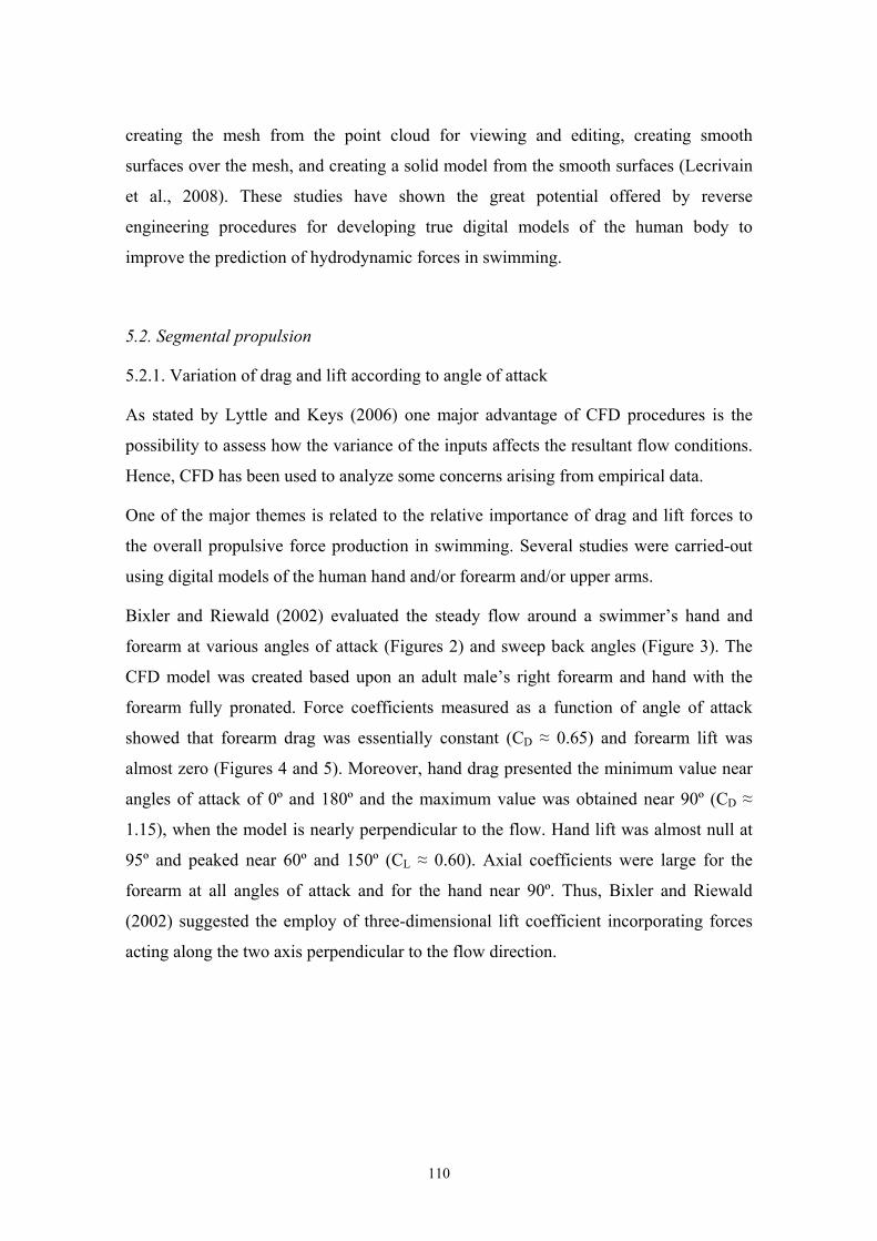
creating the mesh from the point cloud for viewing and editing, creating smooth
surfaces over the mesh, and creating a solid model from the smooth surfaces (Lecrivain
et al., 2008). These studies have shown the great potential offered by reverse
engineering procedures for developing true digital models of the human body to
improve the prediction of hydrodynamic forces in swimming.
5.2. Segmental propulsion
5.2.1. Variation of drag and lift according to angle of attack
As stated by Lyttle and Keys (2006) one major advantage of CFD procedures is the
possibility to assess how the variance of the inputs affects the resultant flow conditions.
Hence, CFD has been used to analyze some concerns arising from empirical data.
One of the major themes is related to the relative importance of drag and lift forces to
the overall propulsive force production in swimming. Several studies were carried-out
using digital models of the human hand and/or forearm and/or upper arms.
Bixler and Riewald (2002) evaluated the steady flow around a swimmer’s hand and
forearm at various angles of attack (Figures 2) and sweep back angles (Figure 3). The
CFD model was created based upon an adult male’s right forearm and hand with the
forearm fully pronated. Force coefficients measured as a function of angle of attack
showed that forearm drag was essentially constant (CD ≈ 0.65) and forearm lift was
almost zero (Figures 4 and 5). Moreover, hand drag presented the minimum value near
angles of attack of 0º and 180º and the maximum value was obtained near 90º (CD ≈
1.15), when the model is nearly perpendicular to the flow. Hand lift was almost null at
95º and peaked near 60º and 150º (CL ≈ 0.60). Axial coefficients were large for the
forearm at all angles of attack and for the hand near 90º. Thus, Bixler and Riewald
(2002) suggested the employ of three-dimensional lift coefficient incorporating forces
acting along the two axis perpendicular to the flow direction.
110
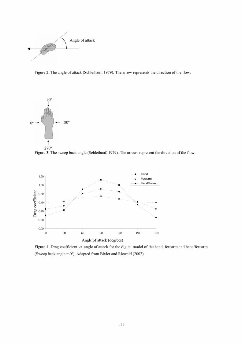
Angle of attack
Figure 2: The angle of attack (Schleihauf, 1979). The arrow represents the direction of the flow.
90º
180º 0º
Figure 3: The sweep back angle (Schleihauf, 1979). The arrows represent the direction of the flow. 270º
0.00
0.20
0.40
0.60
0.80
1.00
1.20
0 30 60 90 120 150 180
Hand
Forearm
Hand/Forearm
Dra
g co
effic
ient
Angle of attack (degrees) Figure 4: Drag coefficient vs. angle of attack for the digital model of the hand, forearm and hand/forearm
(Sweep back angle = 0º). Adapted from Bixler and Riewald (2002).
111
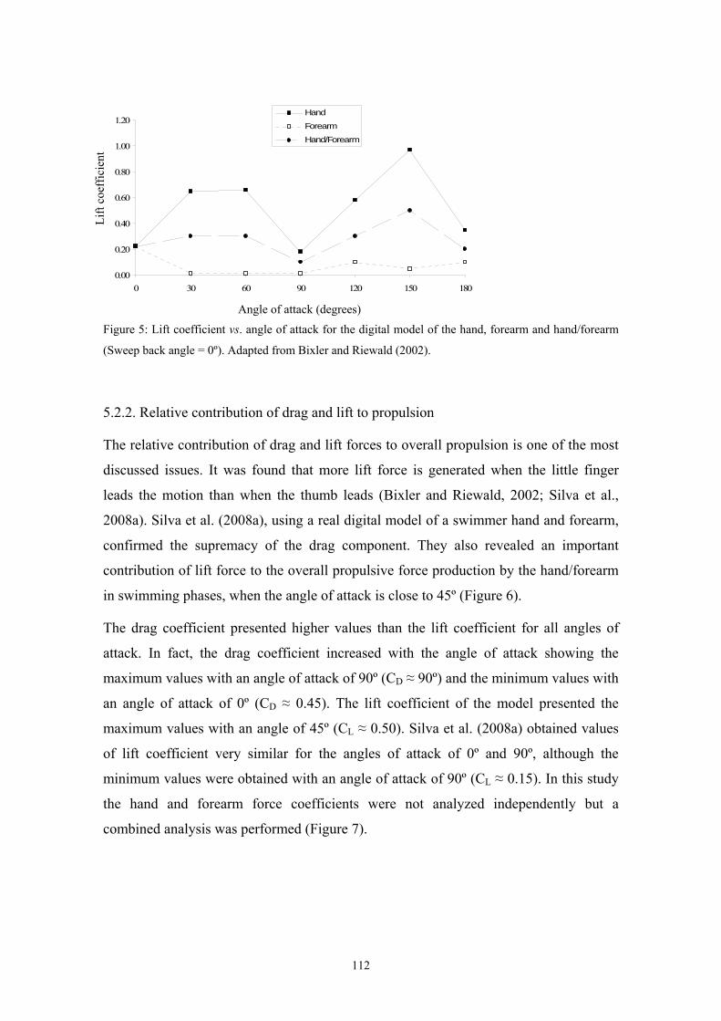
0.00
0.20
0.40
0.60
0.80
1.00
1.20
0 30 60 90 120 150 180
HandForearm
Hand/Forearm
Lift
coef
ficie
nt
Angle of attack (degrees)
Figure 5: Lift coefficient vs. angle of attack for the digital model of the hand, forearm and hand/forearm
(Sweep back angle = 0º). Adapted from Bixler and Riewald (2002).
5.2.2. Relative contribution of drag and lift to propulsion
The relative contribution of drag and lift forces to overall propulsion is one of the most
discussed issues. It was found that more lift force is generated when the little finger
leads the motion than when the thumb leads (Bixler and Riewald, 2002; Silva et al.,
2008a). Silva et al. (2008a), using a real digital model of a swimmer hand and forearm,
confirmed the supremacy of the drag component. They also revealed an important
contribution of lift force to the overall propulsive force production by the hand/forearm
in swimming phases, when the angle of attack is close to 45º (Figure 6).
The drag coefficient presented higher values than the lift coefficient for all angles of
attack. In fact, the drag coefficient increased with the angle of attack showing the
maximum values with an angle of attack of 90º (CD ≈ 90º) and the minimum values with
an angle of attack of 0º (CD ≈ 0.45). The lift coefficient of the model presented the
maximum values with an angle of 45º (CL ≈ 0.50). Silva et al. (2008a) obtained values
of lift coefficient very similar for the angles of attack of 0º and 90º, although the
minimum values were obtained with an angle of attack of 90º (CL ≈ 0.15). In this study
the hand and forearm force coefficients were not analyzed independently but a
combined analysis was performed (Figure 7).
112
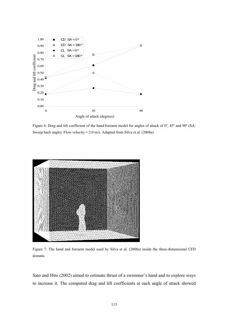
0.00
0.10
0.20
0.30
0.40
0.50
0.60
0.70
0.80
0.90
1.00
0 45 90
CD SA = 0 º
CD SA = 180 º
CL SA = 0 º
CL SA = 180 º
Dra
g an
d lif
t coe
ffic
ient
Angle of attack (degrees)
Figure 6: Drag and lift coefficient of the hand/forearm model for angles of attack of 0º, 45º and 90º (SA:
Sweep back angle). Flow velocity = 2.0 m/s. Adapted from Silva et al. (2008a).
Figure 7: The hand and forearm model used by Silva et al. (2008a) inside the three-dimensional CFD
domain.
Sato and Hito (2002) aimed to estimate thrust of a swimmer’s hand and to explore ways
to increase it. The computed drag and lift coefficients at each angle of attack showed
113
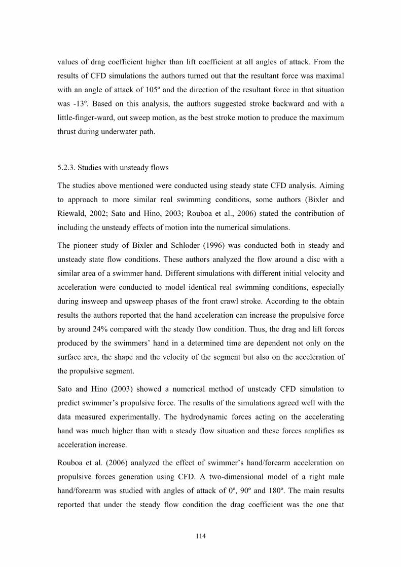
values of drag coefficient higher than lift coefficient at all angles of attack. From the
results of CFD simulations the authors turned out that the resultant force was maximal
with an angle of attack of 105º and the direction of the resultant force in that situation
was -13º. Based on this analysis, the authors suggested stroke backward and with a
little-finger-ward, out sweep motion, as the best stroke motion to produce the maximum
thrust during underwater path.
5.2.3. Studies with unsteady flows
The studies above mentioned were conducted using steady state CFD analysis. Aiming
to approach to more similar real swimming conditions, some authors (Bixler and
Riewald, 2002; Sato and Hino, 2003; Rouboa et al., 2006) stated the contribution of
including the unsteady effects of motion into the numerical simulations.
The pioneer study of Bixler and Schloder (1996) was conducted both in steady and
unsteady state flow conditions. These authors analyzed the flow around a disc with a
similar area of a swimmer hand. Different simulations with different initial velocity and
acceleration were conducted to model identical real swimming conditions, especially
during insweep and upsweep phases of the front crawl stroke. According to the obtain
results the authors reported that the hand acceleration can increase the propulsive force
by around 24% compared with the steady flow condition. Thus, the drag and lift forces
produced by the swimmers’ hand in a determined time are dependent not only on the
surface area, the shape and the velocity of the segment but also on the acceleration of
the propulsive segment.
Sato and Hino (2003) showed a numerical method of unsteady CFD simulation to
predict swimmer’s propulsive force. The results of the simulations agreed well with the
data measured experimentally. The hydrodynamic forces acting on the accelerating
hand was much higher than with a steady flow situation and these forces amplifies as
acceleration increase.
Rouboa et al. (2006) analyzed the effect of swimmer’s hand/forearm acceleration on
propulsive forces generation using CFD. A two-dimensional model of a right male
hand/forearm was studied with angles of attack of 0º, 90º and 180º. The main results
reported that under the steady flow condition the drag coefficient was the one that
114
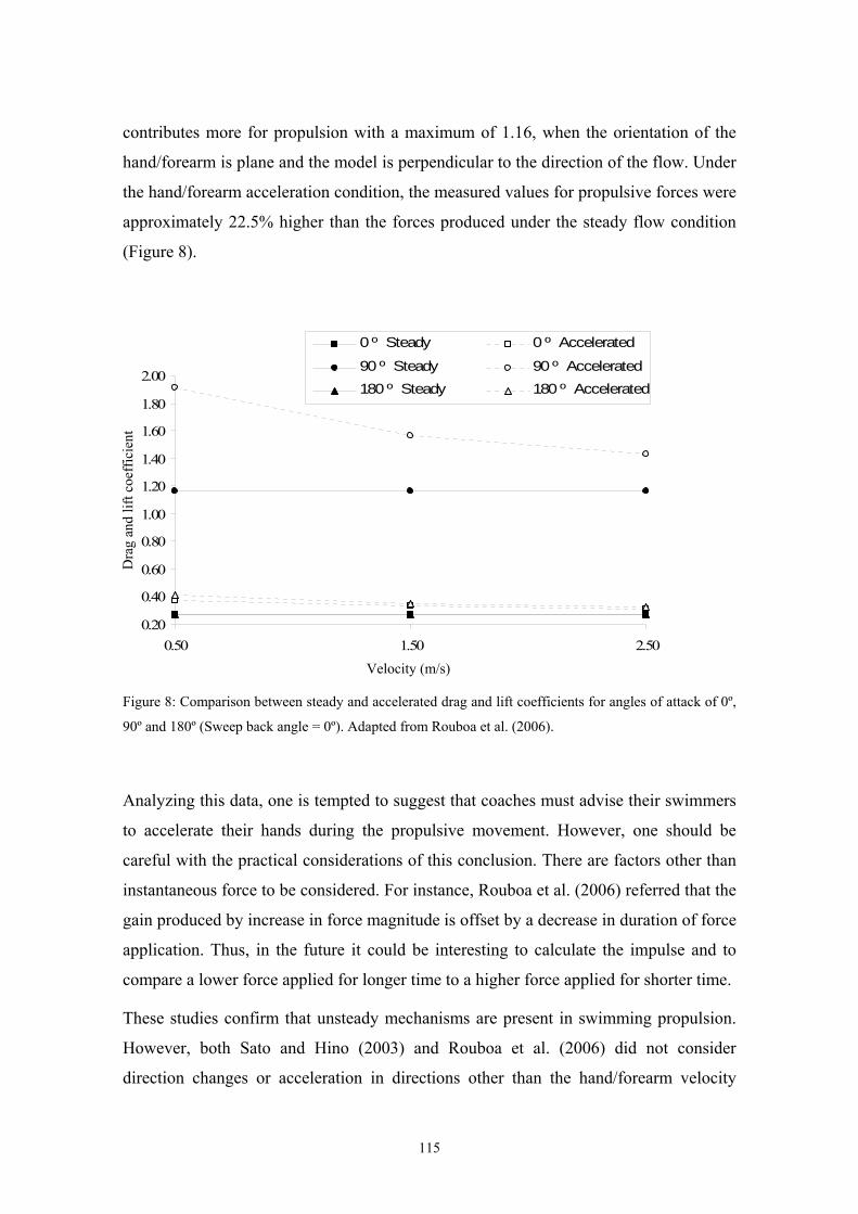
contributes more for propulsion with a maximum of 1.16, when the orientation of the
hand/forearm is plane and the model is perpendicular to the direction of the flow. Under
the hand/forearm acceleration condition, the measured values for propulsive forces were
approximately 22.5% higher than the forces produced under the steady flow condition
(Figure 8).
0.20
0.40
0.60
0.80
1.00
1.20
1.40
1.60
1.80
2.00
0.50 1.50 2.50
0 º Steady 0 º Accelerated
90 º Steady 90 º Accelerated180 º Steady 180 º Accelerated
Dra
g an
d lif
t coe
ffic
ient
Velocity (m/s)
Figure 8: Comparison between steady and accelerated drag and lift coefficients for angles of attack of 0º,
90º and 180º (Sweep back angle = 0º). Adapted from Rouboa et al. (2006).
Analyzing this data, one is tempted to suggest that coaches must advise their swimmers
to accelerate their hands during the propulsive movement. However, one should be
careful with the practical considerations of this conclusion. There are factors other than
instantaneous force to be considered. For instance, Rouboa et al. (2006) referred that the
gain produced by increase in force magnitude is offset by a decrease in duration of force
application. Thus, in the future it could be interesting to calculate the impulse and to
compare a lower force applied for longer time to a higher force applied for shorter time.
These studies confirm that unsteady mechanisms are present in swimming propulsion.
However, both Sato and Hino (2003) and Rouboa et al. (2006) did not consider
direction changes or acceleration in directions other than the hand/forearm velocity
115
direction. Swimmers do not move their hands and arms in a steady velocity or linear
direction. The swimmer’s hand/forearm motion is a combination of movements in
horizontal (forward-backward), lateral (inward-outward) and vertical (upward-
downward) directions. Therefore, it seems essential to include other aspects of unsteady
motions, namely the multi-axis rotations, with the rotation of the mesh relative to the
flow. Regarding this issue, Lecrivain et al. (2008) used unsteady CFD procedures to
analyze the performance of a lower arm amputee swimmer.
5.2.4. Contribution of arm’s action to propulsion
Lecrivain et al. (2008) used a complex CFD mesh model, representing the swimmer
body and its upper arm. The model, including the arm rotation relative to the body and a
body roll movement relative to the water, interacted dynamically with the fluid flow.
The unsteady evolution of the interaction was achieved through dynamic
moving/deforming meshes for the particular body parts which have a relative motion
with full computation of the interaction carried out at each successive time step. In
further research, the authors intend to analyze the effect of different arm rotations and
body roll movements in the arm propulsive force production. Lecrivain et al. (2008)
were also able to note that the arm provided effective propulsion through most of the
stroke, and this must be considered when studying the arm propulsion. In fact, Gardano
and Dabnichki (2006) underlined the importance of the analysis of the entire arm rather
than different parts of it. Thus, the authors concluded that drag profiles differed
substantially with the elbow flexion angle, as the maximum value could vary by as
much as 40%. In addition, Gardano and Dabnichki (2006) stated that maximum drag
force was achieved by 160º of elbow angle. A prolonged plateau between 50º and 140º
indicated greater momentum generated at 160º in comparison with the other
configurations. This fact suggests a strong possibility for the existence of an optimal
elbow angle for the generation of a maximum propulsive force. However, these findings
are only possible to confirm if an entire model of the swimmer’s arm, its movement
relative to the body and the body’s movement relative to the water is computed with
CFD. This concern seems an interesting topic to address in further studies.
116
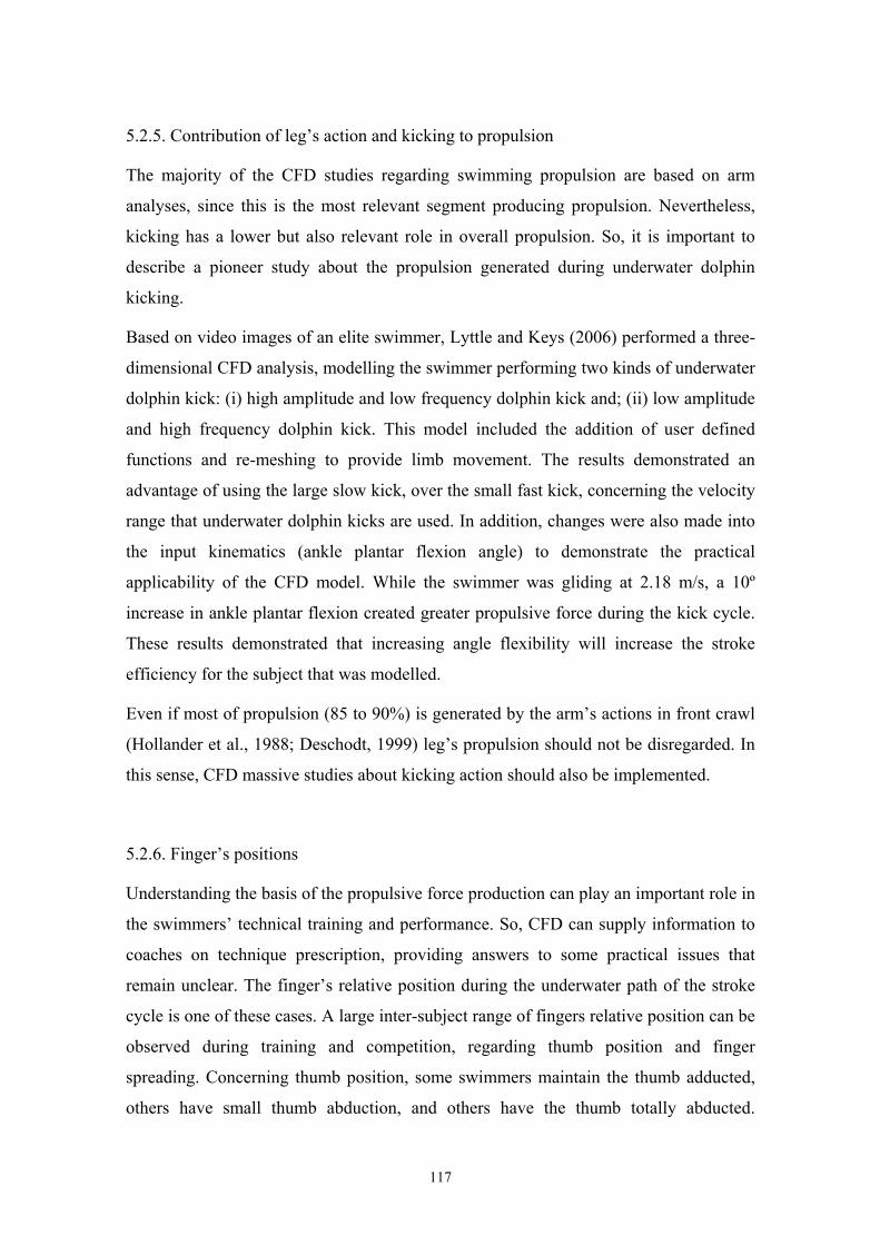
5.2.5. Contribution of leg’s action and kicking to propulsion
The majority of the CFD studies regarding swimming propulsion are based on arm
analyses, since this is the most relevant segment producing propulsion. Nevertheless,
kicking has a lower but also relevant role in overall propulsion. So, it is important to
describe a pioneer study about the propulsion generated during underwater dolphin
kicking.
Based on video images of an elite swimmer, Lyttle and Keys (2006) performed a three-
dimensional CFD analysis, modelling the swimmer performing two kinds of underwater
dolphin kick: (i) high amplitude and low frequency dolphin kick and; (ii) low amplitude
and high frequency dolphin kick. This model included the addition of user defined
functions and re-meshing to provide limb movement. The results demonstrated an
advantage of using the large slow kick, over the small fast kick, concerning the velocity
range that underwater dolphin kicks are used. In addition, changes were also made into
the input kinematics (ankle plantar flexion angle) to demonstrate the practical
applicability of the CFD model. While the swimmer was gliding at 2.18 m/s, a 10º
increase in ankle plantar flexion created greater propulsive force during the kick cycle.
These results demonstrated that increasing angle flexibility will increase the stroke
efficiency for the subject that was modelled.
Even if most of propulsion (85 to 90%) is generated by the arm’s actions in front crawl
(Hollander et al., 1988; Deschodt, 1999) leg’s propulsion should not be disregarded. In
this sense, CFD massive studies about kicking action should also be implemented.
5.2.6. Finger’s positions
Understanding the basis of the propulsive force production can play an important role in
the swimmers’ technical training and performance. So, CFD can supply information to
coaches on technique prescription, providing answers to some practical issues that
remain unclear. The finger’s relative position during the underwater path of the stroke
cycle is one of these cases. A large inter-subject range of fingers relative position can be
observed during training and competition, regarding thumb position and finger
spreading. Concerning thumb position, some swimmers maintain the thumb adducted,
others have small thumb abduction, and others have the thumb totally abducted.
117
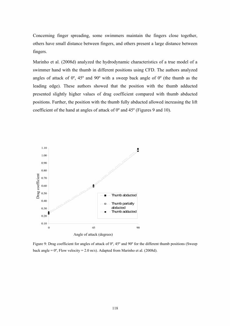
Concerning finger spreading, some swimmers maintain the fingers close together,
others have small distance between fingers, and others present a large distance between
fingers.
Marinho et al. (2008d) analyzed the hydrodynamic characteristics of a true model of a
swimmer hand with the thumb in different positions using CFD. The authors analyzed
angles of attack of 0º, 45º and 90º with a sweep back angle of 0º (the thumb as the
leading edge). These authors showed that the position with the thumb adducted
presented slightly higher values of drag coefficient compared with thumb abducted
positions. Further, the position with the thumb fully abducted allowed increasing the lift
coefficient of the hand at angles of attack of 0º and 45º (Figures 9 and 10).
0.10
0.20
0.30
0.40
0.50
0.60
0.70
0.80
0.90
1.00
1.10
0 45
Dra
g co
effic
ient
90
Thumb abducted
Thumb partiallyabductedThumb adducted
Angle of attack (degrees)
Figure 9: Drag coefficient for angles of attack of 0º, 45º and 90º for the different thumb positions (Sweep
back angle = 0º, Flow velocity = 2.0 m/s). Adapted from Marinho et al. (2008d).
118
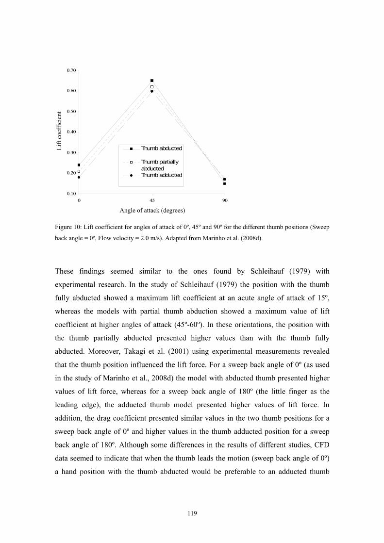
0.10
0.20
0.30
0.40
0.50
0.60
0.70
0 45
Lift
coef
ficie
nt
90
Thumb abducted
Thumb partiallyabductedThumb adducted
Angle of attack (degrees)
Figure 10: Lift coefficient for angles of attack of 0º, 45º and 90º for the different thumb positions (Sweep
back angle = 0º, Flow velocity = 2.0 m/s). Adapted from Marinho et al. (2008d).
These findings seemed similar to the ones found by Schleihauf (1979) with
experimental research. In the study of Schleihauf (1979) the position with the thumb
fully abducted showed a maximum lift coefficient at an acute angle of attack of 15º,
whereas the models with partial thumb abduction showed a maximum value of lift
coefficient at higher angles of attack (45º-60º). In these orientations, the position with
the thumb partially abducted presented higher values than with the thumb fully
abducted. Moreover, Takagi et al. (2001) using experimental measurements revealed
that the thumb position influenced the lift force. For a sweep back angle of 0º (as used
in the study of Marinho et al., 2008d) the model with abducted thumb presented higher
values of lift force, whereas for a sweep back angle of 180º (the little finger as the
leading edge), the adducted thumb model presented higher values of lift force. In
addition, the drag coefficient presented similar values in the two thumb positions for a
sweep back angle of 0º and higher values in the thumb adducted position for a sweep
back angle of 180º. Although some differences in the results of different studies, CFD
data seemed to indicate that when the thumb leads the motion (sweep back angle of 0º)
a hand position with the thumb abducted would be preferable to an adducted thumb
119
position. In addition, when analyzing the resultant force coefficient, Marinho et al.
(2008d) found that the position with the thumb abducted presented higher values than
the positions with the thumb partially abducted and adducted at angles of attack of 0º
and 45º. At an angle of attack of 90º, the position with the thumb adducted presented the
highest value of resultant force coefficient.
Marinho et al. (2008e) aimed to study the effect of finger spread on the propulsive force
production in swimming using CFD. The authors studied the hand with different finger
spreads: fingers close together, fingers with little distance spread (a mean intra finger
distance of 0.32 cm, tip to tip), and fingers with large distance spread (0.64 cm, tip to
tip), similar to the procedure used by Schleihauf (1979). Marinho et al. (2008e) found
that for attack angles higher than 30º, the model with little distance between fingers
presented higher values of drag coefficient when compared with the models with fingers
closed and with large finger spread. For attack angles of 0º, 15º and 30º, the values of
drag coefficient were very similar in the three models of the swimmer’s hand. In
addition, the lift coefficient seemed to be independent of the finger spreading,
presenting little differences between the three models (Figures 11 and 12). Nevertheless,
Marinho et al. (2008e) were able to note slightly lower values of lift coefficient for the
position with larger distance between fingers. These results suggested that fingers
slightly spread can be used by swimmers to create more propulsive force.
0.10
0.30
0.50
0.70
0.90
1.10
0 15 30 45 60 75 90
Large distancespreadLittle distancespreadFingers closetogether
Dra
g co
effic
ient
Angle of attack (degrees)
Figure 11: Drag coefficient for angles of attack of 0º, 15º, 30º, 45º, 60º, 75º and 90º for the different finger
spread positions (Sweep back angle = 0º, Flow velocity = 2.0 m/s). Adapted from Marinho et al. (2008e).
120
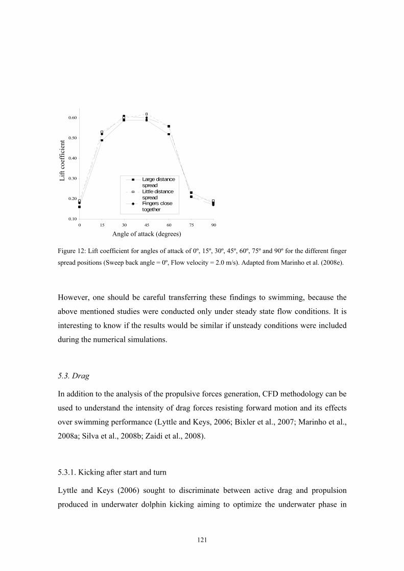
0.10
0.20
0.30
0.40
0.50
0.60
0 15 30 45 60 75 90
Large distancespreadLittle distancespreadFingers closetogether
Lift
coef
ficie
nt
Angle of attack (degrees)
Figure 12: Lift coefficient for angles of attack of 0º, 15º, 30º, 45º, 60º, 75º and 90º for the different finger
spread positions (Sweep back angle = 0º, Flow velocity = 2.0 m/s). Adapted from Marinho et al. (2008e).
However, one should be careful transferring these findings to swimming, because the
above mentioned studies were conducted only under steady state flow conditions. It is
interesting to know if the results would be similar if unsteady conditions were included
during the numerical simulations.
5.3. Drag
In addition to the analysis of the propulsive forces generation, CFD methodology can be
used to understand the intensity of drag forces resisting forward motion and its effects
over swimming performance (Lyttle and Keys, 2006; Bixler et al., 2007; Marinho et al.,
2008a; Silva et al., 2008b; Zaidi et al., 2008).
5.3.1. Kicking after start and turn
Lyttle and Keys (2006) sought to discriminate between active drag and propulsion
produced in underwater dolphin kicking aiming to optimize the underwater phase in
121
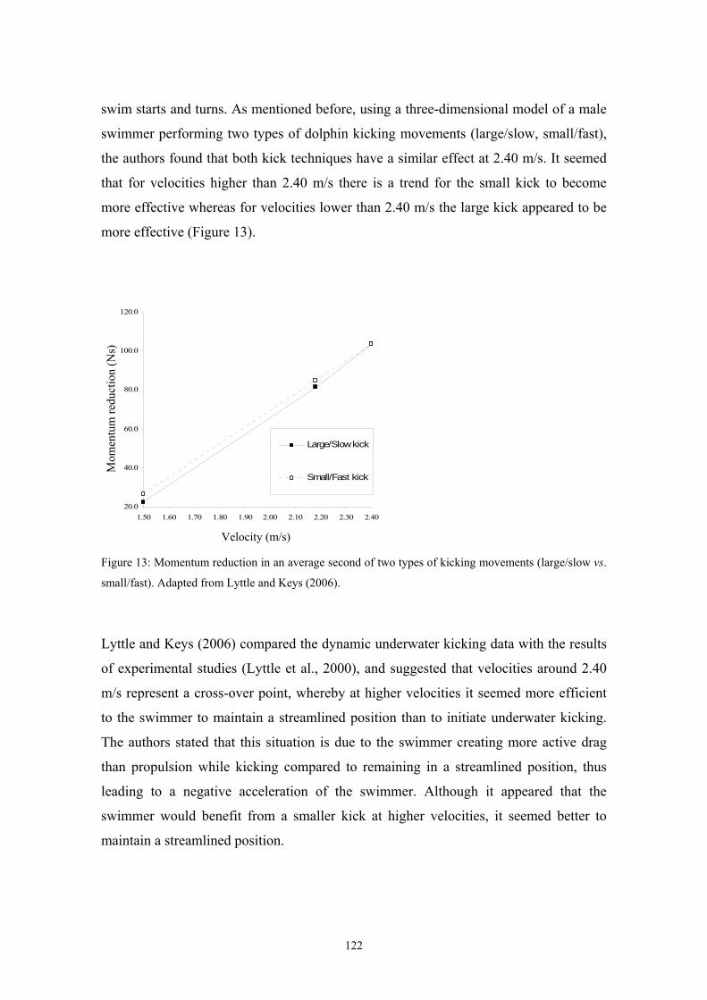
swim starts and turns. As mentioned before, using a three-dimensional model of a male
swimmer performing two types of dolphin kicking movements (large/slow, small/fast),
the authors found that both kick techniques have a similar effect at 2.40 m/s. It seemed
that for velocities higher than 2.40 m/s there is a trend for the small kick to become
more effective whereas for velocities lower than 2.40 m/s the large kick appeared to be
more effective (Figure 13).
20.0
40.0
60.0
80.0
100.0
120.0
1.50 1.60 1.70 1.80 1.90 2.00 2.10 2.20 2.30 2.40
Large/Slow kick
Small/Fast kick
Mom
entu
m re
duct
ion
(Ns)
Velocity (m/s)
Figure 13: Momentum reduction in an average second of two types of kicking movements (large/slow vs.
small/fast). Adapted from Lyttle and Keys (2006).
Lyttle and Keys (2006) compared the dynamic underwater kicking data with the results
of experimental studies (Lyttle et al., 2000), and suggested that velocities around 2.40
m/s represent a cross-over point, whereby at higher velocities it seemed more efficient
to the swimmer to maintain a streamlined position than to initiate underwater kicking.
The authors stated that this situation is due to the swimmer creating more active drag
than propulsion while kicking compared to remaining in a streamlined position, thus
leading to a negative acceleration of the swimmer. Although it appeared that the
swimmer would benefit from a smaller kick at higher velocities, it seemed better to
maintain a streamlined position.
122
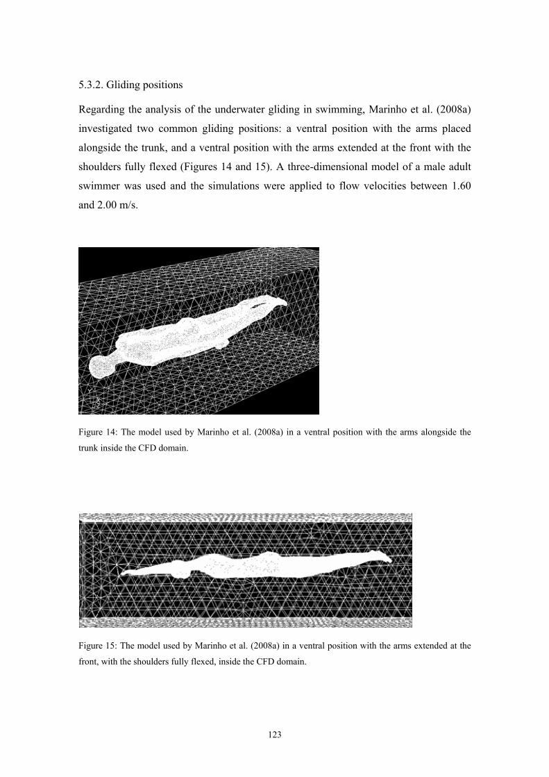
5.3.2. Gliding positions
Regarding the analysis of the underwater gliding in swimming, Marinho et al. (2008a)
investigated two common gliding positions: a ventral position with the arms placed
alongside the trunk, and a ventral position with the arms extended at the front with the
shoulders fully flexed (Figures 14 and 15). A three-dimensional model of a male adult
swimmer was used and the simulations were applied to flow velocities between 1.60
and 2.00 m/s.
Figure 14: The model used by Marinho et al. (2008a) in a ventral position with the arms alongside the
trunk inside the CFD domain.
Figure 15: The model used by Marinho et al. (2008a) in a ventral position with the arms extended at the
front, with the shoulders fully flexed, inside the CFD domain.
123
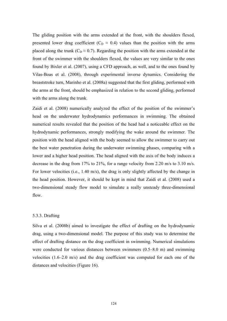
The gliding position with the arms extended at the front, with the shoulders flexed,
presented lower drag coefficient (CD ≈ 0.4) values than the position with the arms
placed along the trunk (CD ≈ 0.7). Regarding the position with the arms extended at the
front of the swimmer with the shoulders flexed, the values are very similar to the ones
found by Bixler et al. (2007), using a CFD approach, as well, and to the ones found by
Vilas-Boas et al. (2008), through experimental inverse dynamics. Considering the
breaststroke turn, Marinho et al. (2008a) suggested that the first gliding, performed with
the arms at the front, should be emphasized in relation to the second gliding, performed
with the arms along the trunk.
Zaidi et al. (2008) numerically analyzed the effect of the position of the swimmer’s
head on the underwater hydrodynamics performances in swimming. The obtained
numerical results revealed that the position of the head had a noticeable effect on the
hydrodynamic performances, strongly modifying the wake around the swimmer. The
position with the head aligned with the body seemed to allow the swimmer to carry out
the best water penetration during the underwater swimming phases, comparing with a
lower and a higher head position. The head aligned with the axis of the body induces a
decrease in the drag from 17% to 21%, for a range velocity from 2.20 m/s to 3.10 m/s.
For lower velocities (i.e., 1.40 m/s), the drag is only slightly affected by the change in
the head position. However, it should be kept in mind that Zaidi et al. (2008) used a
two-dimensional steady flow model to simulate a really unsteady three-dimensional
flow.
5.3.3. Drafting
Silva et al. (2008b) aimed to investigate the effect of drafting on the hydrodynamic
drag, using a two-dimensional model. The purpose of this study was to determine the
effect of drafting distance on the drag coefficient in swimming. Numerical simulations
were conducted for various distances between swimmers (0.5–8.0 m) and swimming
velocities (1.6–2.0 m/s) and the drag coefficient was computed for each one of the
distances and velocities (Figure 16).
124
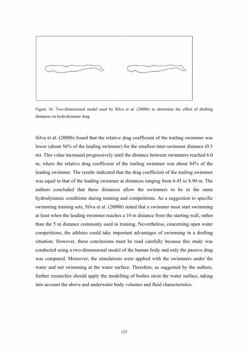
Figure 16: Two-dimensional model used by Silva et al. (2008b) to determine the effect of drafting
distances on hydrodynamic drag.
Silva et al. (2008b) found that the relative drag coefficient of the trailing swimmer was
lower (about 56% of the leading swimmer) for the smallest inter-swimmer distance (0.5
m). This value increased progressively until the distance between swimmers reached 6.0
m, where the relative drag coefficient of the trailing swimmer was about 84% of the
leading swimmer. The results indicated that the drag coefficient of the trailing swimmer
was equal to that of the leading swimmer at distances ranging from 6.45 to 8.90 m. The
authors concluded that these distances allow the swimmers to be in the same
hydrodynamic conditions during training and competitions. As a suggestion to specific
swimming training sets, Silva et al. (2008b) stated that a swimmer must start swimming
at least when the leading swimmer reaches a 10 m distance from the starting wall, rather
than the 5 m distance commonly used in training. Nevertheless, concerning open water
competitions, the athletes could take important advantages of swimming in a drafting
situation. However, these conclusions must be read carefully because this study was
conducted using a two-dimensional model of the human body and only the passive drag
was computed. Moreover, the simulations were applied with the swimmers under the
water and not swimming at the water surface. Therefore, as suggested by the authors,
further researches should apply the modelling of bodies on/at the water surface, taking
into account the above and underwater body volumes and fluid characteristics.
125
5.3.4. Relative contribution of drag components to total drag
In addition to the analysis of the hydrodynamic drag under different body positions,
some authors attempted to investigate the contribution of skin-friction drag, pressure
drag and wave drag to the total drag (Bixler et al., 2007; Marinho et al., 2008a; Zaidi et
al., 2008). In human swimming, the total drag is composed of the skin-friction drag,
pressure drag and wave drag. Skin-friction drag is attributed to the forces tending to
slow the water flowing along the body surface of the swimmer. It depends on the
velocity of the flow, the surface area of the body and the characteristics of the surface.
Pressure drag is caused by the pressure differential between the front and the rear of the
swimmer and it is proportional to the square of swimming velocity, the density of water
and the cross sectional are of the swimmer. Finally, swimming at the water surface is
constrained by the formation of surface waves leading to wave drag. However, the three
mentioned studies only considered hydrodynamic drag depending on the skin-friction
drag and pressure drag since the model was placed underwater. In the study of Bixler et
al. (2007) the swimmer model was placed at a water depth of 0.75 m. In the study of
Zaidi et al. (2008) the swimmer was positioned 1.50 m below the water surface while
Marinho et al. (2008a) used a swimmer model placed at a water depth of 0.90 m. This
assumption was proven to be correct using experimental tests (Lyttle et al., 1999;
Vennell et al., 2006). Lyttle et al. (1999) concluded that there is no significant wave
drag when a typical adult swimmer is at least 0.60 m under the water’s surface. More
recently, Vennell et al. (2006) found that at 0.75 m below the water surface was below
the location where “surface effects” begin to influence significantly the drag force.
Indeed, the authors showed that to avoid significant wave drag a swimmer must be
deeper than 1.8 chest depths and 2.8 chest depths below the water surface for velocities
of 0.9 and 2.0 m/s, respectively. It seems interesting attempting to conduct similar
studies with a CFD approach, requiring the simulation of the interface between air and
water.
Bixler et al. (2007) showed that pressure drag represented around 75% of the total
hydrodynamic drag. Although pressure drag was dominant, skin-friction drag was by no
means insignificant, representing 27% and 25% of total drag for gliding velocities of
1.50 and 2.25 m/s, respectively. The significantly higher percentage of pressure drag
was as well found by Marinho et al. (2008a) and Zaidi et al. (2008). Zaidi et al. (2008)
126
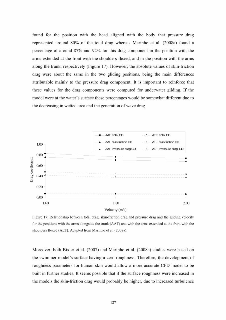
found for the position with the head aligned with the body that pressure drag
represented around 80% of the total drag whereas Marinho et al. (2008a) found a
percentage of around 87% and 92% for this drag component in the position with the
arms extended at the front with the shoulders flexed, and in the position with the arms
along the trunk, respectively (Figure 17). However, the absolute values of skin-friction
drag were about the same in the two gliding positions, being the main differences
attributable mainly to the pressure drag component. It is important to reinforce that
these values for the drag components were computed for underwater gliding. If the
model were at the water’s surface these percentages would be somewhat different due to
the decreasing in wetted area and the generation of wave drag.
0.00
0.20
0.40
0.60
0.80
1.00
1.60 1.80 2.00
AAT Total CD AEF Total CD
AAT Skin-friction CD AEF Skin-friction CD
AAT Pressure drag CD AEF Pressure drag CD
Dra
g co
effic
ient
Velocity (m/s)
Figure 17: Relationship between total drag, skin-friction drag and pressure drag and the gliding velocity
for the positions with the arms alongside the trunk (AAT) and with the arms extended at the front with the
shoulders flexed (AEF). Adapted from Marinho et al. (2008a).
Moreover, both Bixler et al. (2007) and Marinho et al. (2008a) studies were based on
the swimmer model’s surface having a zero roughness. Therefore, the development of
roughness parameters for human skin would allow a more accurate CFD model to be
built in further studies. It seems possible that if the surface roughness were increased in
the models the skin-friction drag would probably be higher, due to increased turbulence
127
around the surface (Bixler et al., 2007). On the other hand, if the surface roughness were
increased the pressure drag could be reduced. Massey (1989) stated that the boundary
layer, which would be mainly laminar, would change into a turbulent one. When the
flow is laminar, separation of the boundary layer at the body surface starts almost as
soon as the pressure gradient becomes adverse, and a larger wake forms. However,
when the flow is turbulent, separation is delayed and the corresponding wake is smaller,
thus decreasing pressure drag (Polidori et al., 2006; Marinho et al., 2008a).
5.3.5. Swimsuits and training equipments
The study of the effects of different swimsuits on the hydrodynamic drag was one of the
first applications of CFD in swimming (Fluent, 2004). As stated in the introduction
section, the cooperation between Speedo® and Fluent® allowed developing some well-
known swimsuits, as FastSkin® and LZR® suits. However, Speedo® is not the only
manufacture using numerical solutions to enhance the swimsuits. Arena® in straight
cooperation with the Mox Institute at Politecnico de Milano (Milan, Italy) developed
mathematical models and simulations to measure the water flow around the swimmer
using the PowerSkin® new generation swimsuits. With CFD methodology it is possible
to analyze the velocity and the direction of the water flow around the body, thus
allowing evaluating the different paths due to different suit tissues and body
compressive effects. However, the major research conducted in this field is performed
with great secrets. To our knowledge, there is no study published about this issue.
Therefore, new lines of research concerning the effects of different swimsuits on
performance should be attempted in the future. For instance, it seems important to
evaluate the use of different suit tissues, different ways to sew the tissue pieces,
different suit types and sizes, and the effect of swim suits upon wobbling body masses,
and full body (and body parts) compression during different swimming phases.
Based on these assumptions, it seems CFD can also be an interesting tool to help
developing training equipments. For example, different paddles, fins, kickboards, pull-
buoys, cups, swim goggles and training aids used by the swimmers can be evaluated
using numerical simulation techniques. The effect of different lane lines in the
swimmer’s performance can also be analysed with a CFD approach.
128
6. CFD methods contribution for near future development of swimming science
As one can note, CFD can be a good approach to study swimming hydrodynamics and
can contribute to the development of swimming science. However, despite the
important steps forward in the application of CFD in swimming, there are several
aspects that can be improved.
The concern of Gardano and Dabnichki (2006) and Lecrivain et al. (2008) of taking into
account the entire arm when studying the arm propulsion should be considered. In
addition, the effect of whole body movements on the arm propulsive force production
must also be attempted in the future. Moreover, the analysis of hydrodynamic forces
must be conducted with the body at the water surface, taking into account the interface
between air and water. This fact will require the simulation of two different fluids
around the swimmer body, allowing including wave drag in the evaluations. The
modelling of whole body swimming movements seems to be the next step in swimming
research applying CFD methodology.
Furthermore, the development of roughness parameters for human skin would allow a
more accurate CFD model to be built in future studies, to more accurately understand
the relative contribution of skin-friction drag to the total hydrodynamic drag. As stated
by Bixler et al. (2007), as CFD methods continue to develop, it will be possible to
evaluate the effects of different techniques, body positions, and swimwear on
performance, thus optimizing swimmers’ performance.
Therefore, with these assumptions we can state some ideas and some purposes for other
studies following and complementing the ones we have presented during this chapter:
1. Propulsive forces studies:
(i) The computation of the ideal shape for a swimmers hand, arm, foot, or other body
segment;
(ii) The computation of the effects of acceleration (positive and negative), and multi-
axis rotations on lift and drag;
129
(iii) The computation of the added mass of water as an inertial effect to the body
displacement during the stroke cycle;
(iv) The computation of the effect of different stroke patterns on propulsion in front
crawl, backstroke, butterfly and breaststroke.
2. Drag forces studies:
(i) The computation of total drag force on a swimmer moving through the water, and the
relative contribution of pressure drag, skin-friction drag and wave production drag for
the total drag;
(ii) The effect of different forms of streamlining on the hydrodynamic drag;
(iii) The computation of the effect of underwater turbulence and waves on a swimmers
motion;
(iv) The effect on hydrodynamic drag of “dragging” off a swimmer, either in an
adjacent lane and/or behind;
(v) The evaluation of the effects of different swimming suits and other equipments on
hydrodynamic drag;
(vi) The computations of the ideal body shape and size to minimise drag;
(vii) Eventually, to calculate active drag, using moving meshes would be an important
task.
7. Conclusion
In summary we can state that the recent evidence strongly suggests that CFD technique
can be considered as an interesting new approach for evaluation of swimming
hydrodynamic forces. In the near future, as in the present, CFD will provide valorous
arguments for defining new swimming techniques or equipments.
Therefore, within this chapter we attempted to present the already applied CFD
techniques and to propose new procedures that may be used by the research community
130
in further studies under similar research topics in order to improve swimming
performance.
On the other hand, we tried to make some contribution to the dissemination of the main
results, not only stimulating young researchers in the fulfilment of the existent gap
between the sports sciences and other sciences (hydrodynamics in the present case) but
also to the spreading of the use of this recent technique (in sports context) by the ones
that are really interested in the development of new concepts and applications.
We also aimed to contribute to the application of the knowledge gathered into practical
situations, trying to introduce some new insights in the designing of new propulsive
techniques in swimming, new ways of streamlining the body during the displacement or
even the development of new materials (suits and others) helping the swimmer moving
faster.
8. References
Arellano, R., Nicoli-Terrés, J.M., Redondo, J.M. (2006). Fundamental hydrodynamics of swimming
propulsion. Portuguese Journal of Sport Sciences, 6(Suppl. 2), 15-20.
Barsky, S., Delgado-Buscalioni, R., Coveney, P.V. (2004). Comparison of molecular dynamics with
hybrid continuum-molecular dynamics for a single tethered polymer in a solvent. Journal of
Chemical Physics, 121, 2403-2411.
Berger, M.A., de Groot, G., Hollander, A.P. (1995). Hydrodynamic drag and lift forces on human hand
arm models. Journal of Biomechanics, 28, 125-133.
Berthier, B., Bouzebar, R., Legallais, L. (2002). Blood flow patterns in an automatically realistic coronary
vessel influence of three different reconstruction models. Journal of Biomechanics, 35, 1347-1356.
Bixler, B.S., Schloder, M. (1996). Computational fluid dynamics: an analytical tool for the 21st century
swimming scientist. Journal of Swimming Research, 11, 4-22.
Bixler, B.S., Riewald, S. (2002). Analysis of swimmer’s hand and arm in steady flow conditions using
computational fluid dynamics. Journal of Biomechanics, 35, 713-717.
Bixler, B., Pease, D., Fairhurst, F. (2007). The accuracy of computational fluid dynamics analysis of the
passive drag of a male swimmer. Sports Biomechanics, 6, 81-98.
Boulding, N., Yim, S.S., Keshavarz-Moore, E., Ayazi Shamlou, P., Berry, M. (2002). Ultra scaledown to
predict filtering centrifugation of secreted antibody fragments from fungal broth. Biotechnology
and Bioengineering, 79, 381-388.
131
Colwin, C. (1984). Fluid dynamics: vortex circulation in swimming propulsion. In: T.F. Welsh (Ed.),
American Swimming Coaches Association World Clinic Yearbook 1984, pp. 38-46. Fort
Lauderdale: American Swimming Coaches Association.
Dabnichki, P., Avital, E. (2006). Influence of the position of crew members on aerodynamics
performance of two-man bobsleigh. Journal of Biomechanics, 39, 2733-2742.
Deschodt, V. (1999). Relative contribution of arms and legs in human to propulsion in 25 m sprint front
crawl swimming. European Journal of Applied Physiology, 80, 192-199.
Dickinson, M.H. (2000). How animals move: an integrative view. Science, 288, 100-106.
Dickinson, M.H., Gotz, K.G. (1993). Unsteady aerodynamic performance of model wings at low
Reynolds numbers. Journal of Experimental Biology, 174, 45-64.
Dickinson, M.H., Lehmann, F.O., Sane, S.P. (1999). Wing rotation and the aerodynamic basis of insect
flight. Science, 284, 1954-1960.
Ellington, C.P., Van den Berg, C., Willmott, A.P., Thomas, A.L. (1996). Leading-edge vortices in insect
flight. Nature, 384, 626-630.
Fluent (2004). Speedo goes for gold with CFD. Fluent News, 13(1), 4-6.
Gage, K.L., Gartner, M.J., Burgreen, G.W., Wagner, W.R. (2002). Predicting membrane oxygenator
pressure drop using computational fluid dynamics. Artificial Organs, 26, 600-607.
Gardano, P., Dabnichki, P. (2006). On hydrodynamics of drag and lift of the human arm. Journal of
Biomechanics, 39, 2767-2773.
Guerra, D., Ricciardi, L., Laborde, J.C., Domenech, S. (2007). Predicting gaseous pollutant dispersion
around a workplace. Journal of Occupational and Environmental Hygiene, 4, 619-633.
Hamdani, H., Sun, M. (2001). A study on the mechanism of high-lift generation by an airfoil in unsteady
motion at low Reynolds number. Acta Mechanica Sinica, 17, 97-114.
Hannah, R.K. (2002). Can CFD make a performance difference in Sport? In: S. Ujihashi (Ed.), The
Engineering of Sport, pp. 17-30. Oxford: Blackwell Science.
Hollander, A., de Groot, G., Schenau, G., Kahman, R., Toussaint, H. (1988). Contribution of the legs to
propulsion in front crawl swimming. In: B. Ungerechts, K. Wilke, K. Reischle (Eds.), Swimming
Science V, pp. 39-43. Champaign, Illinois: Human Kinetics Books.
Kellar, W.P., Pearse, S.R.G., Savill, A.M. (1999). Formula 1 car wheel aerodynamics. Sports
Engineering, 2, 203-212.
Lecrivain, G., Slaouti, A., Payton, C., Kennedy, I. (2008). Using reverse engineering and computational
fluid dynamics to investigate a lower arm amputee swimmer’s performance. Journal of
Biomechanics, 41, 2855-2859.
132
Lui, H. (2002). Computational biological fluid dynamics: digitizing and visualizing animal swimming
and flying. Integrative and Comparative Biology, 42, 1050-1059.
Liu, H., Kawachi, K. (1998). A numerical study of insect flight. Journal of Computational Physics, 146,
124-156.
Liu, H., Wassersug, R., Kawachi, K. (1996). A computational fluid dynamics study of tadpole swimming.
Journal of Experimental Biology, 199, 1245-1260.
Liu, H., Wassersug, R., Kawachi, K. (1997). The three-dimensional hydrodynamics of tadpole
locomotion. Journal of Experimental Biology, 200, 2807-2819.
Liu, H., Ellington, C., Kawachi, K. (1998). A computational fluid dynamic study of hawkmoth hovering.
Journal of Experimental Biology, 201, 461-477.
Lyttle, A., Keys, M. (2006). The application of computational fluid dynamics for technique prescription
in underwater kicking. Portuguese Journal of Sport Sciences, 6(Suppl. 2), 233-235.
Lyttle, A.D., Blanksby, B.A., Elliott, B.C., Lloyd, D.G. (1999). Optimal depth for streamlined gliding. In:
K.L. Keskinen, P.V. Komi, A.P. Hollander (Eds.), Biomechanics and Medicine in Swimming VIII,
pp. 165-170. Jyvaskyla: Gummerus Printing.
Lyttle, A., Blanksby, B., Elliot, B., Lloyd, D. (2000). Net forces during tethered simulation of underwater
streamlined gliding and kicking technique of the freestyle turn. Journal of Sports Sciences, 18,
801-807.
Marinho, D.A., Reis, V.M., Alves, F.B., Vilas-Boas, J.P., Machado, L., Silva, A.J. Rouboa, A.I. (2008a).
The hydrodynamic drag during gliding in swimming. Journal of Applied Biomechanics (in press).
Marinho, D.A., Reis, V.M., Alves, F.B., Vilas-Boas, J.P., Machado, L., Rouboa, A.I., Silva, A.J. (2008b).
The use of Computational Fluid Dynamics in swimming research. International Journal for
Computational Vision and Biomechanics (in press).
Marinho, D.A., Reis, V.M., Vilas-Boas, J.P., Alves, F.B., Machado, L., Rouboa, A.I., Silva, A.J. (2008c).
Design of a three-dimensional hand/forearm model to apply Computational Fluid Dynamics.
Brazilian Archives of Biology and Technology (in press).
Marinho, D.A., Rouboa, A.I., Alves, F.B., Vilas-Boas, J.P., Machado, L., Reis, V.M., Silva, A.J. (2008d).
Hydrodynamic analysis of different thumb positions in swimming. Journal of Sports Science and
Medicine (in press).
Marinho, D.A., Barbosa, T.M., Reis, V.M., Kjendlie, P.L., Alves, F.B., Vilas-Boas, J.P., Machado, L.,
Silva, A.J., Rouboa, A.I. (2008e). Swimming propulsion forces are enhanced by a small finger
spread. Journal of Applied Biomechanics (under revision).
133
Marshall, I., Zhao, S., Papathanasopoulou, P., Hoskins, P., Xui, Y. (2004). MRI and CFD studies of
pulsatile flow in healthy and stenosed carotid bifurcation models. Journal of Biomechanics, 37,
679-687.
Massey, B.S. (1989). Mechanics of Fluids. London: Chapman & Hall.
Pallis, J.M., Banks, D.W., Okamoto, K.K. (2000). 3D computational fluid dynamics in competitive sail,
yatch and windsurfer design. In: F. Subic, M. Haake (Eds.), The Engineering of Sport: Research,
Development and Innovation, pp. 75-79. Oxford: Blackwell Science.
Polidori, G., Taiar, R., Fohanno, S., Mai, T.H., Lodini, A. (2006). Skin-friction drag analysis from the
forced convection modeling in simplified underwater swimming. Journal of Biomechanics, 39,
2535-2541.
Ramamurti, R., Sandberg, W.C. (2002). A three-dimensional computational study of the aerodynamic
mechanisms of insect flight. Journal of Experimental Biology, 205, 1507-1518.
Rouboa, A., Silva, A., Leal, L., Rocha, J., Alves, F. (2006). The effect of swimmer’s hand/forearm
acceleration on propulsive forces generation using computational fluid dynamics. Journal of
Biomechanics, 39, 1239-1248.
Ruiz, P., Ruiz, F., López, A., Español, C. (2005). Computational fluid dynamics simulations of the
airflow in the human nasal cavity. Acta Otorrinolaringológica Española, 56, 403-410.
Sanders, R.H. (1999). Hydrodynamic characteristics of a swimmer’s hand. Journal of Applied
Biomechanics, 15, 3-26.
Sane, S. (2003). The aerodynamics of insect flight. Journal of Experimental Biology, 206, 4191-4208.
Sato, Y., Hino, T. (2002). Estimation of thrust of swimmer's hand using CFD. In: Proceedings of 8th
Symposium on Nonlinear and Free-Surface Flows, pp. 71-75. Hiroshima.
Sato, Y., Hino, T. (2003). Estimation of thrust of swimmer's hand using CFD. In: Proceedings of the
Second International Symposium on Aqua Bio-Mechanisms, 81-86. Honolulu.
Schleihauf, R.E. (1979). A hydrodynamic analysis of swimming propulsion. In: J. Terauds, E.W.
Bedingfield (Eds.), Swimming III, pp. 70-109. Baltimore: University Park Press.
Silva, A., Rouboa, A., Leal, L., Rocha, J., Alves, F., Moreira, A., Reis, V., Vilas-Boas, J.P. (2005).
Measurement of swimmer's hand/forearm propulsive forces generation using computational fluid
dynamics. Portuguese Journal of Sport Sciences, 5, 288-297.
Silva, A.J., Marinho, D.A., Reis, V.M., Alves, F., Vilas-Boas, J.P., Machado, L., Rouboa, A.I. (2008a).
Study of the propulsive potential of the hand and forearm in swimming. Medicine and Science in
Sports and Exercise, 40(5 Suppl.), S212.
134
Silva, A.J., Rouboa, A., Moreira, A., Reis, V.M., Alves, F., Vilas-Boas, J.P., Marinho, D.A. (2008b).
Analysis of drafting effects in swimming using computational fluid dynamics. Journal of Sports
Science and Medicine, 7(1), 60-66.
Sun, M., Tang, J. (2002). Unsteady aerodynamic force generation by a model fruit fly wing in flapping
motion. Journal of Experimental Biology, 205, 55-70.
Takagi, H., Shimizu, Y., Kurashima, A., Sanders, R. (2001). Effect of thumb abduction and adduction on
hydrodynamic characteristics of a model of the human hand. In: J. Blackwell, R. Sanders (Eds.),
Proceedings of Swim Sessions of the XIX International Symposium on Biomechanics in Sports, pp.
122-126. San Francisco: University of San Francisco.
Toussaint, H.M., Van den Berg, C., Beek, W.J. (2002). "Pumped-up propulsion" during front crawl
swimming. Medicine and Science in Sports and Exercise, 34, 314-319.
Venetsanos, A.G., Huld, T., Adams, P., Bartzis, J.G. (2003). Source, dispersion and combustion
modelling of an accidental release of hydrogen in an urban environment. Journal of Hazardous
Materials, 105(1-3), 1-25.
Vennell, R., Pease, D.L., Wilson, B.D. (2006). Wave drag on human swimmers. Journal of
Biomechanics, 31, 664-671.
Vilas-Boas, J.P., Costa, L., Fernandes, R., Ribeiro, J., Figueiredo, P., Marinho, D., Silva, A., Rouboa, A.,
Machado, L. (2008). Determinação do arrasto hidrodinâmico em duas posições de deslize, por
dinâmica inversa e por simulação computacional (CFD). In: II Congreso Internacional de
Biomecánica de Venezuela. Isla de Margarita, Venezuela: Ministério del Poder Popular para el
Deporte de Venezuela.
Wang, Z.J. (2000). Two dimensional mechanism for insect hovering. Physical Review Letters, 85, 2216-
2219.
Wood, T.C. (1977). A fluid dynamic analysis of the propulsive potential of the hand and forearm in
swimming. Master of Science Thesis. Halifax: Dalhouise University Press.
Yim P., Demarco, K., Castro, M.A., Cebral, J. (2005). Characterization of shear stress on the wall of the
carotid artery using magnetic resonance imaging and computational fluid dynamics. Studies in
Health Technology and Informatics, 113, 412-442.
Zaidi, H., Taiar, R., Fohanno, S., Polidori, G. (2008). Analysis of the effect of swimmer’s head position
on swimming performance using computational fluid dynamics. Journal of Biomechanics, 41,
1350-1358.
135

Main conclusions
136
Main conclusions
The main aim of the present thesis was to study the mechanism of swimming propulsion
using CFD through a three-dimensional analysis of the swimmer’s hand and forearm.
Hence, the main purpose of our first studies was to be able to apply the numerical
simulation techniques using a three-dimensional model of the swimmer body. After the
propulsive force measurements using a true three-dimensional model of a human
segment have been demonstrated, it was possible to improve previous CFD analysis,
including a more realistic model of the swimmer hand and forearm. Additionally, the
CFD methodology was applied to address some practical concerns of swimmers and
coaches, such as the finger’s relative position during the underwater path of the stroke
cycle.
Nevertheless, there are several further CFD procedures that must be accomplished to
understand deeply the generation of propulsive force in swimming. The applied
numerical simulations were still only an approximation to actually model a swimmer’s
arm. As stated during this thesis, one should note that the simulation of water flow
conditions around the hand and forearm when treated as one segment do not illustrate
the complexity of propulsion generating process. Moreover, the CFD analyses were
carried-out under steady flow conditions. One should be aware that these conditions do
not truly represent the swimmer’s movements. Therefore, further research should
consider the movement at the wrist, elbow, and shoulder joints and the aspects of
unsteady motion, such as accelerations and multi-axis rotations of the propelling
segments, must be added to the modelling of the arm propulsion. However, taking into
account the above considerations, we can state the main conclusions of the present
thesis:
1. The drag coefficient was the main responsible for the hand and forearm propulsion,
with a maximum value of force corresponding to an angle of attack of 90º.
2. An important contribution of the lift force to the overall force generation by the
hand/forearm in swimming phases was observed with angles of attack of 30º, 45º and
60º, especially when the little finger leads the motion.
137
3. The hand model with the thumb adducted presented higher values of drag coefficient
compared with thumb abducted models. The model with the thumb fully abducted
allowed increasing the lift coefficient of the hand at angles of attack of 0º and 45º.
4. The resultant force coefficient showed that the hand model with the thumb fully
abducted presented higher values than the positions with the thumb partially abducted
and adducted at angles of attack of 0º and 45º. At an angle of attack of 90º, the model
with the thumb adducted presented the highest value of resultant force coefficient.
5. The hand model with little distance between fingers presented higher values of drag
coefficient than the models with fingers closed and fingers with large distance spread.
The values for the lift coefficient presented little differences between the models with
different finger’s spreading.
6. The results suggested that for hand positions in which the lift force can play an
important role, the abduction of the thumb may be better, whereas at higher angles of
attack, in which the drag force is dominant, the adduction of the thumb may be
preferable. Furthermore, it is suggested that fingers slightly spread could allow the hand
to create more force during swimming.
138

References
139
References
Alves, F., Marinho, D., Leal, L., Rouboa, A., Silva, A. (2007). 3-D computational fluid dynamics of the
hand and forearm in swimming. Medicine and Science in Sports and Exercise, 39(Suppl. 1), S9.
Arellano, R., Nicoli-Terrés, J.M., Redondo, J.M. (2006). Fundamental hydrodynamics of swimming
propulsion. Portuguese Journal of Sport Sciences, 6(Suppl. 2), 15-20.
Aritan, S., Dabnichki, P., Bartlett, R. (1997). Program for generation of three-dimensional finite element
mesh form magnetic resonance imaging scans of human limbs. Medical Engineering and Physics,
19, 681-689.
Barsky, S., Delgado-Buscalioni, R., Coveney, P.V. (2004). Comparison of molecular dynamics with
hybrid continuum-molecular dynamics for a single tethered polymer in a solvent. Journal of
Chemical Physics, 121, 2403-2411.
Berger, M. (1996). Force generation and efficiency in front crawl swimming. PhD Thesis. Amsterdam:
Faculty of Human Movement Sciences, Vrije Universiteit.
Berger, M.A., de Groot, G., Hollander, A.P. (1995). Hydrodynamic drag and lift forces on human hand
arm models. Journal of Biomechanics, 28, 125-133.
Berger, M.A., de Groot, G., Hollander, A.P. (1997). Influence of hand shape on force generation during
swimming. In: B.O. Eriksson, L. Gullstrand (Eds.), Proceedings of the XII FINA World Congress
on Sports Medicine, pp. 389-396. Goteborg: Chalmers Reproservice.
Berger, M.A., Hollander, A.P., de Groot, G. (1999). Determining propulsive force in front crawl
swimming: a comparison of two methods. Journal of Sports Sciences, 17, 97-105.
Berthier, B., Bouzebar, R., Legallais, L. (2002). Blood flow patterns in an automatically realistic coronary
vessel influence of three different reconstruction models. Journal of Biomechanics, 35, 1347-1356.
Bixler, B., Schloder, M. (1996). Computational fluid dynamics: an analytical tool for the 21st century
swimming scientist. Journal of Swimming Research, 11, 4-22.
Bixler, B., Riewald, S. (2002). Analysis of swimmer’s hand and arm in steady flow conditions using
computational fluid dynamics. Journal of Biomechanics, 35, 713-717.
Bixler, B., Pease, D., Fairhurst, F. (2007). The accuracy of computational fluid dynamics analysis of the
passive drag of a male swimmer. Sports Biomechanics, 6, 81-98.
Boulding, N., Yim, S.S., Keshavarz-Moore, E., Ayazi Shamlou, P., Berry, M. (2002). Ultra scaledown to
predict filtering centrifugation of secreted antibody fragments from fungal broth. Biotechnology
and Bioengineering, 79, 381-388.
140
Candalai, R.S., Reddy, N.P. (1992). Stress distribution in a physical buttock model: effect of simulated
bone geometry. Journal of Biomechanics, 15, 493-504.
Chatard, J.C., Lavoie, J.M., Bourgoins, B., Lacour, J.R. (1990). The contribution of passive drag as a
determinant of swimming performance. International Journal of Sports Medicine, 11, 367-372.
Colwin, C. (1984). Fluid dynamics: vortex circulation in swimming propulsion. In: T.F. Welsh (Ed.),
American Swimming Coaches Association World Clinic Yearbook 1984, pp. 38-46. Fort
Lauderdale: American Swimming Coaches Association.
Colwin, C. (1992). Swimming into the 21th Century. Champaign, Illinois: Leisure Press.
Cossor, J., Mason, B. (2001). Swim start performances at the Sydney 2000 Olympic Games. In: J.
Blackwell, R. Sanders (Eds.), Proceedings of Swim Sessions of the XIX Symposium on
Biomechanics in Sports, pp. 70-74. San Francisco: University of San Francisco.
Counsilman, J. (1968). The Science of Swimming. Englewood Cliffs: Prenctice-Hall Inc.
Dabnichki, P., Avital, E. (2006). Influence of the position of crew members on aerodynamics
performance of two-man bobsleigh. Journal of Biomechanics, 39, 2733-2742.
Deschodt, V. (1999). Relative contribution of arms and legs in human to propulsion in 25 m sprint front
crawl swimming. European Journal of Applied Physiology, 80, 192-199.
Dickinson, M.H. (2000). How animals move: an integrative view. Science, 288, 100-106.
Dickinson, M.H., Gotz, K.G. (1993). Unsteady aerodynamic performance of model wings at low
Reynolds numbers. Journal of Experimental Biology, 174, 45-64.
Dickinson, M.H., Lehmann, F.O., Sane, S.P. (1999). Wing rotation and the aerodynamic basis of insect
flight. Science, 284, 1954-1960.
Ellington, C.P., Van den Berg, C., Willmott, A.P., Thomas, A.L. (1996). Leading-edge vortices in insect
flight. Nature, 384, 626-630.
Fluent (2004). Speedo goes for gold with CFD. Fluent News, 13(1), 4-6.
Gage, K.L., Gartner, M.J., Burgreen, G.W., Wagner, W.R. (2002). Predicting membrane oxygenator
pressure drop using computational fluid dynamics. Artificial Organs, 26, 600-607.
Gardano, P., Dabnichki, P. (2006). On hydrodynamics of drag and lift of the human arm. Journal of
Biomechanics, 39, 2767-2773.
Guerra, D., Ricciardi, L., Laborde, J.C., Domenech, S. (2007). Predicting gaseous pollutant dispersion
around a workplace. Journal of Occupational and Environmental Hygiene, 4, 619-633.
Guimarães, A., Hay, J. (1985). A mechanical analysis of the grab starting technique in swimming.
International Journal of Sports Biomechanics, 1, 25-35.
141
Hamdani, H., Sun, M. (2001). A study on the mechanism of high-lift generation by an airfoil in unsteady
motion at low Reynolds number. Acta Mechanica Sinica, 17, 97-114.
Hannah, R.K. (2002). Can CFD make a performance difference in Sport? In: S. Ujihashi (Ed.), The
Engineering of Sport, pp. 17-30. Oxford: Blackwell Science.
Hollander, A.P., de Groot, G., Van Ingen Schenau, G.L., Toussaint, H.M., de Best, H., Peeters, W.,
Meulemans, A., Schreurs, A.W. (1986). Measurement of active drag during crawl arm stroke
swimming. Journal of Sports Sciences, 4, 21-30.
Hollander, A., de Groot, G., Schenau, G., Kahman, R., Toussaint, H. (1988). Contribution of the legs to
propulsion in front crawl swimming. In: B. Ungerechts, K. Wilke, K. Reischle (Eds.), Swimming
Science V, pp. 39-43. Champaign, Illinois: Human Kinetics Books.
Jiskoot, J., Clarys, J.P. (1975). Body resistance on and under the water surface. In: L. Lewillie, J.P. Clarys
(Eds.), Swimming II, pp. 105-109. Baltimore: University Park Press.
Kellar, W.P., Pearse, S.R.G., Savill, A.M. (1999). Formula 1 car wheel aerodynamics. Sports
Engineering, 2, 203-212.
Lauder, M., Dabnichki, P., Bartlett, R. (2001). Improved accuracy and reliability of sweepback angle,
pitch angle and hand velocity calculations in swimming. Journal of Biomechanics, 34, 31-39.
Lecrivain, G., Slaouti, A., Payton, C., Kennedy, I. (2008). Using reverse engineering and computational
fluid dynamics to investigate a lower arm amputee swimmer’s performance. Journal of
Biomechanics, 41, 2855-2859.
Lee, J., Mellifont, R., Winstanley, J., Burkett, B. (2008). Body roll in simulated freestyle swimming.
International Journal of Sports Medicine, 29, 569-573.
Liu, H. (2002). Computational biological fluid dynamics: digitizing and visualizing animal swimming
and flying. Integrative and Comparative Biology, 42, 1050-1059.
Liu, H., Kawachi, K. (1998). A numerical study of insect flight. Journal of Computational Physics, 146,
124-156.
Liu, H., Wassersug, R., Kawachi, K. (1996). A computational fluid dynamics study of tadpole swimming.
Journal of Experimental Biology, 199, 1245-1260.
Liu, H., Wassersug, R., Kawachi, K. (1997). The three-dimensional hydrodynamics of tadpole
locomotion. Journal of Experimental Biology, 200, 2807-2819.
Liu, H., Ellington, C., Kawachi, K. (1998). A computational fluid dynamic study of hawkmoth hovering.
Journal of Experimental Biology, 201, 461-477.
Long, Q., Xu, X.Y., Collins, M.W., Griffith, T.M., Bourne, M. (1998). The combination of magnetic
resonance angiography and computational fluid dynamics: a critical review. Critical Reviews in
Biomedical Engineering, 26, 227-274.
142
Lyttle, A., Keys, M. (2006). The application of computational fluid dynamics for technique prescription
in underwater kicking. Portuguese Journal of Sport Sciences, 6(Suppl. 2), 233-235.
Lyttle, A.D., Blanksby, B.A., Elliott, B.C., Lloyd, D.G. (1999). Optimal depth for streamlined gliding. In:
K.L. Keskinen, P.V. Komi, A.P. Hollander (Eds.), Biomechanics and Medicine in Swimming VIII,
pp. 165-170. Jyvaskyla: Gummerus Printing.
Lyttle, A., Blanksby, B., Elliot, B., Lloyd, D. (2000). Net forces during tethered simulation of underwater
streamlined gliding and kicking technique of the freestyle turn. Journal of Sports Sciences, 18,
801-807.
Maglischo, E.W. (2003). Swimming Fastest. The essential reference on training, technique and program
design. Champaign, Illinois: Human Kinetics.
Marinho, D.A., Reis, V.M., Alves, F.B., Vilas-Boas, J.P., Machado, L., Silva, A.J., Rouboa, A.I. (2008).
The hydrodynamic drag during gliding in swimming. Journal of Applied Biomechanics (in press).
Marinho, D.A., Reis, V.M., Alves, F.B., Vilas-Boas, J.P., Machado, L., Rouboa, A.I., Silva, A.J. (2008).
The use of Computational Fluid Dynamics in swimming research. International Journal for
Computational Vision and Biomechanics (in press).
Marinho, D.A., Reis, V.M., Vilas-Boas, J.P., Alves, F.B., Machado, L., Rouboa, A.I., Silva, A.J. (2008).
Design of a three-dimensional hand/forearm model to apply Computational Fluid Dynamics.
Brazilian Archives of Biology and Technology (in press).
Marinho, D.A., Rouboa, A.I., Alves, F.B., Vilas-Boas, J.P., Machado, L., Reis, V.M., Silva, A.J. (2008).
Hydrodynamic analysis of different thumb positions in swimming. Journal of Sports Science and
Medicine (in press).
Marinho, D.A., Barbosa, T.M., Reis, V.M., Kjendlie, P.L., Alves, F.B., Vilas-Boas, J.P., Machado, L.,
Silva, A.J., Rouboa, A.I. (2008). Swimming propulsion forces are enhanced by a small finger
spread. Journal of Applied Biomechanics (under revision).
Marshall, I., Zhao, S., Papathanasopoulou, P., Hoskins, P., Xui, Y. (2004). MRI and CFD studies of
pulsatile flow in healthy and stenosed carotid bifurcation models. Journal of Biomechanics, 37,
679-687.
Massey, B.S. (1989). Mechanics of Fluids. London: Chapman & Hall.
Moreira, A., Rouboa, A., Silva, A., Sousa, L., Marinho, D., Alves, F., Reis, V., Vilas-Boas, J.P., Carneiro,
A., Machado, L. (2006). Computational analysis of the turbulent flow around a cylinder.
Portuguese Journal of Sport Sciences, 6(Suppl. 1), 105.
Pallis, J.M., Banks, D.W., Okamoto, K.K. (2000). 3D computational fluid dynamics in competitive sail,
yatch and windsurfer design. In: F. Subic, M. Haake (Eds.), The Engineering of Sport: Research,
Development and Innovation, pp. 75-79. Oxford: Blackwell Science.
143
Payton, C., Bartlett, R. (1995). Estimating propulsive forces in swimming from three-dimensional
kinematic data. Journal of Sports Sciences, 13, 447-454.
Payton, C., Baltzopoulos, V., Bartlett, R. (2002). Contributions of rotations of the trunk and upper
extremity to hand velocity during front crawl swimming. Journal of Applied Biomechanics, 18,
243.
Polidori, G., Taiar, R., Fohanno, S., Mai, T.H., Lodini, A. (2006). Skin-friction drag analysis from the
forced convection modeling in simplified underwater swimming. Journal of Biomechanics, 39,
2535-2541.
Ramamurti, R., Sandberg, W.C. (2002). A three-dimensional computational study of the aerodynamic
mechanisms of insect flight. Journal of Experimental Biology, 205, 1507-1518.
Rouboa, A., Silva, A., Leal, L., Rocha, J., Alves, F. (2006). The effect of swimmer’s hand/forearm
acceleration on propulsive forces generation using computational fluid dynamics. Journal of
Biomechanics, 39, 1239-1248.
Ruiz, P., Ruiz, F., López, A., Español, C. (2005). Computational fluid dynamics simulations of the
airflow in the human nasal cavity. Acta Otorrinolaringológica Española, 56, 403-410.
Sanders, R.H. (1997). Hydrodynamic characteristics of a swimmer hand with adducted thumb:
implications for technique. In: B.O. Eriksson, L. Gullstrand (Eds.), Proceedings of the XII FINA
World Congress on Sports Medicine, 429-434. Goteborg: Chalmers Reproservice.
Sanders, R.H. (1999). Hydrodynamic characteristics of a swimmer’s hand. Journal of Applied
Biomechanics, 15, 3-26.
Sane, S. (2003). The aerodynamics of insect flight. Journal of Experimental Biology, 206, 4191-4208.
Sato, Y., Hino, T. (2002). Estimation of thrust of swimmer's hand using CFD. In: Proceedings of 8th
Symposium on Nonlinear and Free-Surface Flows, pp. 71-75. Hiroshima.
Sato, Y., Hino, T. (2003). Estimation of thrust of swimmer's hand using CFD. In: Proceedings of the
Second International Symposium on Aqua Bio-Mechanisms, 81-86. Honolulu.
Schleihauf, R.E. (1979). A hydrodynamic analysis of swimming propulsion. In: J. Terauds, E.W.
Bedingfield (Eds), Swimming III, pp. 70-109. Baltimore: University Park Press.
Sidelnik, N.O., Young, B.W. (2006). Optimising the freestyle swimming stroke: the effect of finger
spread. Sports Engineering, 9, 129-135.
Silva, A., Rouboa, A., Leal, L., Rocha, J., Alves, F., Moreira, A., Reis, V., Vilas-Boas, J.P. (2005).
Measurement of swimmer's hand/forearm propulsive forces generation using computational fluid
dynamics. Portuguese Journal of Sport Sciences, 5, 288-297.
144
Silva, A.J., Rouboa, A., Moreira, A., Reis, V., Alves, F., Vilas-Boas, J.P., Marinho, D. (2008). Analysis
of drafting effects in swimming using computational fluid dynamics. Journal of Sports Science
and Medicine, 7(1), 60-66.
Silva, A.J., Marinho, D.A., Reis, V.M., Alves, F., Vilas-Boas, J.P., Machado, L., Rouboa, A.I. (2008).
Study of the propulsive potential of the hand and forearm in swimming. Medicine and Science in
Sports and Exercise, 40(5 Suppl.), S212.
Sun, M., Tang, J. (2002). Unsteady aerodynamic force generation by a model fruit fly wing in flapping
motion. Journal of Experimental Biology, 205, 55-70.
Takagi, H., Shimizu, Y., Kurashima, A., Sanders, R. (2001). Effect of thumb abduction and adduction on
hydrodynamic characteristics of a model of the human hand. In: J. Blackwell, R. Sanders (Eds.),
Proceedings of Swim Sessions of the XIX International Symposium on Biomechanics in Sports, pp.
122-126. San Francisco: University of San Francisco.
Toussaint, H.M., Van den Berg, C., Beek, W.J. (2002). "Pumped-up propulsion" during front crawl
swimming. Medicine and Science in Sports and Exercise, 34, 314-319.
Tu, H.K., Matheny, A., Goldgof, D.B., Bunke, H. (1995). Left ventricular boundary detection from
spatio-temporal volumetric computer tomography images. Computerized Medical Imaging and
Graphics, 19, 27-46.
Ungerechts, B., Klauck, J. (2006). Consequences of unsteady flow effects for functional attribution of
swimming strokes. Portuguese Journal of Sport Sciences, 6(Suppl. 2), 109-111.
Venetsanos, A.G., Huld, T., Adams, P., Bartzis, J.G. (2003). Source, dispersion and combustion
modelling of an accidental release of hydrogen in an urban environment. Journal of Hazardous
Materials, 105(1-3), 1-25.
Vennell, R., Pease, D.L., Wilson, B.D. (2006). Wave drag on human swimmers. Journal of
Biomechanics, 31, 664-671.
Vilas-Boas, J.P., Cruz, M.J., Sousa, F., Conceição, F., Carvalho, J.M. (2000). Integrated kinematic and
dynamic analysis of two track-start techniques. In: R. Sanders, Y. Hong (Eds.), Proceedings of the
XVIII International Symposium on Biomechanics in Sports, Applied Program – Application of
Biomechanical Study in Swimming, pp. 113-117. Hong Kong: The Chinese University Press.
Vilas-Boas, J.P., Costa, L., Fernandes, R., Ribeiro, J., Figueiredo, P., Marinho, D., Silva, A., Rouboa, A.,
Machado, L. (2008). Determinação do arrasto hidrodinâmico em duas posições de deslize, por
dinâmica inversa e por simulação computacional (CFD). In: II Congreso Internacional de
Biomecánica de Venezuela. Isla de Margarita, Venezuela: Ministério del Poder Popular para el
Deporte de Venezuela.
Wang, Z.J. (2000). Two dimensional mechanism for insect hovering. Physical Review Letters, 85, 2216-
2219.
145
Wood, T.C. (1977). A fluid dynamic analysis of the propulsive potential of the hand and forearm in
swimming. Master of Science Thesis. Halifax: Dalhouise University Press.
Yim P., Demarco, K., Castro, M.A., Cebral, J. (2005). Characterization of shear stress on the wall of the
carotid artery using magnetic resonance imaging and computational fluid dynamics. Studies in
Health Technology and Informatics, 113, 412-442.
Zaidi, H., Taiar, R., Fohanno, S., Polidori, G. (2008). Analysis of the effect of swimmer’s head position
on swimming performance using computational fluid dynamics. Journal of Biomechanics, 41,
1350-1358.
Study 1
Marinho, D.A., Reis, V.M., Alves, F.B., Vilas-Boas, J.P., Machado, L., Silva, A.J., Rouboa, A.I. (2008).
The hydrodynamic drag during the gliding in swimming. Journal of Applied Biomechanics (in
press).
Study 2
Marinho, D.A., Reis, V.M., Alves, F.B., Vilas-Boas, J.P., Machado, L., Rouboa, A.I., Silva, A.J. (2008).
The use of Computational Fluid Dynamics in swimming research. International Journal for
Computational Vision and Biomechanics (in press).
Study 3
Marinho, D.A., Reis, V.M., Vilas-Boas, J.P., Alves, F.B., Machado, L., Rouboa, A.I., Silva, A.J. (2008).
Design of a three-dimensional hand/forearm model to apply Computational Fluid Dynamics.
Brazilian Archives of Biology and Technology (in press).
Study 4
Marinho, D.A., Vilas-Boas, J.P., Alves, F.B., Machado, L., Barbosa, T.M., Reis, V.M., Rouboa, A.I.,
Silva, A.J. (2008). Computational analysis of the hand and forearm propulsion in swimming.
International Journal of Sports Medicine (under revision).
Study 5
Marinho, D.A., Rouboa, A.I., Alves, F.B., Vilas-Boas, J.P., Machado, L., Reis, V.M., Silva, A.J. (2008).
Hydrodynamic analysis of different thumb positions in swimming. Journal of Sports Science and
Medicine (in press).
Study 6
Marinho, D.A., Barbosa, T.M., Reis, V.M., Kjendlie, P.L., Alves, F.B., Vilas-Boas, J.P., Machado, L.,
Silva, A.J., Rouboa, A.I. (2008). Swimming propulsion forces are enhanced by a small finger
spread. Journal of Applied Biomechanics (under revision).
146
Review
Marinho, D.A., Barbosa, T.M., Kjendlie, P.L., Vilas-Boas, J.P., Alves, F.B., Rouboa, A.I., Silva, A.J.
(2009). Swimming simulation: a new tool for swimming research and practical applications. In: M.
Peters (Ed.), Lecture Notes in Computational Science and Engineering – CFD and Sport Sciences.
Berlin: Springer (in press).
147

Appendix
CXLVIII
Appendix
Letters of acceptance of the in press papers:
Study 1
Marinho, D.A., Reis, V.M., Alves, F.B., Vilas-Boas, J.P., Machado, L., Silva, A.J., Rouboa, A.I. (2008).
The hydrodynamic drag during the gliding in swimming. Journal of Applied Biomechanics (in
press).
Study 2
Marinho, D.A., Reis, V.M., Alves, F.B., Vilas-Boas, J.P., Machado, L., Rouboa, A.I., Silva, A.J. (2008).
The use of Computational Fluid Dynamics in swimming research. International Journal for
Computational Vision and Biomechanics (in press).
Study 3
Marinho, D.A., Reis, V.M., Vilas-Boas, J.P., Alves, F.B., Machado, L., Rouboa, A.I., Silva, A.J. (2008).
Design of a three-dimensional hand/forearm model to apply Computational Fluid Dynamics.
Brazilian Archives of Biology and Technology (in press).
Study 5
Marinho, D.A., Rouboa, A.I., Alves, F.B., Vilas-Boas, J.P., Machado, L., Reis, V.M., Silva, A.J. (2008).
Hydrodynamic analysis of different thumb positions in swimming. Journal of Sports Science and
Medicine (in press).
Review
Marinho, D.A., Barbosa, T.M., Kjendlie, P.L., Vilas-Boas, J.P., Alves, F.B., Rouboa, A.I., Silva, A.J.
(2009). Swimming simulation: a new tool for swimming research and practical applications. In: M.
Peters (Ed.), Lecture Notes in Computational Science and Engineering – CFD and Sport Sciences.
Berlin: Springer (in press).
CXLIX
Date: Wed, 31 Aug 2008 16:43:10 -0400 (EDT)
From: [email protected]
Reply-To: [email protected]
Subject: Journal of Applied Biomechanics - Decision on Manuscript ID JAB-2007-
0223.R1
To: [email protected], [email protected], [email protected]
31-Aug-2008
Dear Prof.:
It is a pleasure to accept your manuscript entitled "The hydrodynamic drag during the
gliding in swimming" in its current form for publication in the Journal of Applied
Biomechanics.
Manuscripts are published in the order of acceptance, so please await further
instructions from our managing editor, Mr. Leon Jeter. He will contact you when the
time approaches for final preparation of your article.
Thank you for your fine contribution. On behalf of the Editors of the Journal of
Applied Biomechanics, we look forward to your continued contributions to the Journal.
Sincerely,
Prof. Thomas Buchanan
Editor-in-Chief, Journal of Applied Biomechanics
João Manuel R. S. Tavares <[email protected]> Thu, Dec 20, 2007 at 7:12 PM
To: Daniel Marinho <[email protected]>
Dear Daniel Marinho,
The review procedure of your manuscript (IJCV&B_12_11_07) entitled “The use of
Computational Fluid Dynamics in swimming research” has been completed.
The referees have recommended its publication. Some minor revisions are suggested
and I would be glad if you would consider them for the final version of your
manuscript.
Please review the attached documents listing the requirements for your revision.
Please note that the final version of your manuscript should be send to us in a pdf file
and also in an editable file (like Microsoft Word or latex file – including all necessary
sources files).
If you have any question, please do not hesitate to contact me.
Thank you very much for your interest in IJCV&B.
Kind regards,
João Tavares
Remetente: "DEXT BABT" <[email protected]>
Data: 27/10/2008 11:45
Assunto: Brazilian Archives of Biology and Technology
Para: [email protected]
Of.0727/08 - BABT
Brazilian Archives of Biology and Technology
Curitiba, October 17th, 2008
Dear Author,
We inform that your article: "Design of a three-dimensional hand/forearm model to
apply Computational Fluid Dynamics", after been submitted to judgment, it was
aproved, however with some comments.
We would like to remind you that the copy to be sent must be in accordance with the
norms for publication (http://www.tecpar.br), you can consult the latest volumes of the
Brazilian Archives of Biology and Technology. We request the devolution of your work
be in the maximum of 20 (twenty) days period.
Yours truly,
Prof. Dr. Carlos Ricardo Soccol
Editor
JOURNAL OF SPORTS SCIENCE & MEDICINE ELECTRONIC JOURNAL (ISSN 1303-2968)
http://www.jssm.org
EDITORIAL OFFICE Hakan Gür, MD, PhD, Journal of Sports Science and Medicine,
Department of Sports Medicine, Medical Faculty of Uludag University, 16059 Bursa, Turkey Phone: +90 (532) 326 82 26 Fax: +90 (224) 442 87 27 E-mail: [email protected]
December 04, 2008 Daniel A. Marinho Universidade da Beira Interior, Departamento de Ciências do Desporto. Rua Marquês d'Ávila e Bolama. 6201-001 Covilhã, Portugal Manuscript: #1036-2008/JSSM TITLE: “HYDRODYNAMIC ANALYSIS OF DIFFERENT THUMB POSITIONS IN SWIMMING” Dear Dr. Marinho, I am glad to inform you that your revised manuscript is accepted for publication in the Journal of Sports Science and Medicine and it will be published in March 2009 issue of JSSM. The manuscript will now be edited for style and format. Please do not hesitate to contact me if you have any questions. Thank you for giving the JSSM the opportunity to publish your work Sincerely, Hakan Gür, MD, PhD Editor-in-Chief
Editor-in-Chief Hakan Gür, TUR Associate Editors-in-Chief Mustafa Atalay, FIN Andrew Lane, UK Roger Ramsbottom, UK Section Editors Aging Michael E. Rogers, USA Children and Exercise Craig A. Williams, UK Computer, Mathematics and Statistics in Sports John Hammond, AU Laboratory Techniques in Exercise Physiology Itzik Weinstein, ISR Metabolism/Endocrinology Allan H.Goldfarb, USA Molecular aspects Mustafa Atalay, FIN Resistance/Strength Training Nicholas A. Ratamess, USA Testing, Performance Roger Ramsbottom, UK Psychology Andrew Lane, UK Respiration J. Richard Coast, USA Sport Supplementation and Drug R. Jay Hoffman, USA Sports Traumatology Nicola Maffulli, UK Combat Sports Special Edition Editors Andrew Lane, UK Marcus Smith, UK Editorial Board Tiago Barbosa, POR Cem S. Bediz, TUR Lee E. Brown, USA Wojtek J.Chodzko-Zajko, USA Jole T. Cramer, USA M.Nedim Doral, TUR Emin Ergen, TUR James Paul Finn, AU Peter Hofmann, AUS Frank I. Katch, USA Justin Keogh, NZ Sadi Kurdak, TUR Erdem Kasikcioglu, TUR Eleftherios Kellis, GRE William J. Kraemer, USA Max J. Kurz, USA Willem van Mechelen, NL Erich Müller, AUS Ken Noakas, AU Tim Noakes, ZA Fadıl Ozyener,TUR Stephane Perrey, FRA Danny M. Pincivero, USA Scott K. Powers, USA Zsolt Radak, HUN Michael Sagiv, ISR Stephen Seiler, NOR Chandan Sen, USA Antonio Spataro, ITA Esma Sürmen-Gür, TUR Peter Tiidus, CAN Kate Webster, AU Darryn S. Willoughby,USA Indexed in SCI Expanded, Focus On: Sports Sci & Med, ISI J Master List, SciSearch, SPORTDiscus, J-Gate, DOAJ, Index Copernicus, SPONET, GEOBASE, EMBASE, EMNursing, ScholarGoogle, Compendex, Scopus
2007 Impact Factor: 0.290

Per-Ludvik Kjendlie <[email protected]> Sun, Sep 14, 2008 at 10:44 PM
To: Daniel Marinho <[email protected]>
Cc: antonio silva <[email protected]>, João Paulo Vilas-Boas <[email protected]>,
Dear Daniel,
I trust that you and Antonio have discussed about the CFD chapter. He proposed you as
the new first author, of whom I believe is an excellent choice. Attached in this mail you
will have the correspondence I have had with the editor of this book. Below is also two
emails (one containing 'guidelines for authors')
Please read it. Please keep it for future needs. Please also respond to the following:
1. Before I write to the editor, I must be sure that you can devote the time needed for
this, and that you agree to be the first author (which you should…). Please bear in mind
that the deadline is 31. December. 08.
2. Please send me your CV (short form) and full contact information. Also the postal
address, I will send you a book as an example of the book-series, there you can see the
lay-out style etc.
Please keep in touch soon. I must contact the editor in a few days.
Best regards
Per-Ludvik
*********************************************
* Per-Ludvik Kjendlie, PhD *
* Associate Professor *
* Department of Physical Performance *
* Norwegian School of Sport Sciences *
* PO box 4014 Ullevaal Stadion *
* N- 0840 OSLO NORWAY *
* Phone +47 2326 2355 / Fax: +47 2223 4220 *
* Cellphone +47 90650249 *
*********************************************
---
Copy of 2 important emails:
-----
email 1. from : Peters, Martin, Springer DE [[email protected]]
Dear Per-Ludvik,
As I mentioned a while ago we are planning to publish a book in the LNCSE series
devoted to CSE topics with applications to sport. We looked through many potential
topics -- everything took longer than expected -- and then it turned out that it makes
sense with the first book of this kind to focus on CFD related topics. This was agreed
with the LNCSE series editors last week. Cf http://www.springer.com/series/3527 for
info on the series and its editors.
You can see a list of the envisaged contributions in the enclosed memo
<<LNCSE_sport_summary_for_authors_11032008.pdf>> . Other topics are sailing,
soccer, Australian football, and ski jumping. For another future book potential topics are
nutrition, metabolism of athletes, biomechanics, other biomedical topics, materials,
other technology-dependent issues.
This brings me now to my question: Would you like, possibly together with scientists of
SINTEF MARINTEK and the Portuguese CFD group mentioned in
http://www.forskning.no/Artikler/2007/desember/1198928487.74 write a contribution
of about 30 pages for the book on your swimming simulation project?
Here are a few additional remarks:
i) It seems to me that teaming up with such an outstanding institute as MARINTEK and
the CFD experts you would be in a very good position to get interesting results, both
from the scientific simulation point-of view and the practical implementation with
swimmers.
ii) You see from the outline of the book that there is another swimming simulation team
in Australia. If you like and think this is useful, you might consider collaborating with
them -- independently of whether this would be reflected in the book contribution.
iii) Here is another option you might like to explore: We have been in touch with Marco
Pilloud, a former professional swimmer, who now has a company in Switzerland for
teaching of swimming. I believe that you could benefit by collaborating with him, since
he could provide very good examples of stroke technique issues which could be good

research problems for your investigations. Have a look at Marco's self-description in the
appendix to this message.
I hope that you like the idea and will join. Swimming simulation is a very challenging
problem, and hence the perfect topic for the planned book. Simultaneously with this
message, I am writing to all authors -- with all of them we have had preliminary
discussion about the book project.
The following info might be useful for you: I shall visit Oslo in April to meet scientists
at SIMULA and the University. I could insert a visit to NIH, too, and this would be
possible in the mornings of either 8th or 9th April.
With best regards,
Martin
Dr Martin Peters
Executive Editor
Mathematics, Computational Science and Engineering
Mathematics Editorial IV
Springer-Verlag
Tiergartenstr. 17
69121 Heidelberg
Germany
Email 2. from editorial assistant at Springer.
Dear Professor Kjendlie,
On request of Dr. Peters I would like to let you know that he would like to suggest
December 31st, 2008, as date of delivery for your contribution to the planned LNCSE
sports volume. The approximate length of your contribution should be 30 pages
(although there is certainly some flexibility).
We would like to take this opportunity to draw your attention to our TEX macro
packages. The easiest way for you to get hold of our TEX macros is to follow the link
"For Authors" at http://www.springer.com and then the link "Author guidelines for book
authors" or to look directly at
http://www.springer.com/authors/book+authors?SGWID=0-154102-12-417900-0
(please make sure to enter the complete URL into your browser field) where you can
find all Springer macro packages. Please pick up the LaTEX 2e macro package
designed for contributed books. Thank you very much in advance.
If you have any additional question, please do not hesitate to get in touch with us again.
Looking forward to hearing from you again,
With kind regards,
Ruth Allewelt
________________________________________
Just click on www.springer.com
for easy and fast access to all Springer publications - and big online savings, too!
Ruth Allewelt
Assistant to Dr. Peters
Mathematics Editorial IV Phone: 06221 487 8409
Springer Fax: 06221 487 68355
Tiergartenstr. 17
69121 Heidelberg
Germany