UNIVERSIDADE ESTADUAL DE CAMPINAS INSTITUTO DE...
105
1 UNIVERSIDADE ESTADUAL DE CAMPINAS INSTITUTO DE GEOCIÊNCIAS EMERSON FERREIRA DE OLIVEIRA RELAÇÕES ENTRE OS PROCESSOS PALEOPEDOGENÉTICOS E SEDIMENTARES NA FORMAÇÃO MARÍLIA DA SERRA DE ECHAPORÃ (GRUPO BAURU, CRETÁCEO SUPERIOR) CAMPINAS 2016
-
Upload
nguyenkhuong -
Category
Documents
-
view
212 -
download
0
Transcript of UNIVERSIDADE ESTADUAL DE CAMPINAS INSTITUTO DE...
1
UNIVERSIDADE ESTADUAL DE CAMPINAS
INSTITUTO DE GEOCIÊNCIAS
EMERSON FERREIRA DE OLIVEIRA
RELAÇÕES ENTRE OS PROCESSOS PALEOPEDOGENÉTICOS E
SEDIMENTARES NA FORMAÇÃO MARÍLIA DA SERRA DE ECHAPORÃ
(GRUPO BAURU, CRETÁCEO SUPERIOR)
CAMPINAS
2016
EMERSON FERREIRA DE OLIVEIRA
RELAÇÕES ENTRE OS PROCESSOS PALEOPEDOGENÉTICOS E
SEDIMENTARES NA FORMAÇÃO MARÍLIA DA SERRA DE ECHAPORÃ
(GRUPO BAURU, CRETÁCEO SUPERIOR)
DISSERTAÇÃO APRESENTADA AO INSTITUTO DE
GEOCIÊNCIAS DA UNICAMP COMO PRÉ-
REQUISITO PARA OBTENÇÃO DO TÍTULO DE
MESTRE EM GEOCIÊNCIAS NA ÁREA DE
GEOLOGIA E RECURSOS NATURAIS
ORIENTADOR: PROF. DR. GIORGIO BASILICI
ESTE EXEMPLAR CORRESPONDE À VERSÃO FINAL
DA TESE DEFENDIDA PELO ALUNO EMERSON FERREIRA
DE OLIVEIRA E ORIENTADO PELO PROF. DR. GIORGIO BASILICI
CAMPINAS
2016
Agência(s) de fomento e nº(s) de processo(s): FAPESP, 2014/13297-4
Ficha catalográficaUniversidade Estadual de CampinasBiblioteca do Instituto de GeociênciasCássia Raquel da Silva - CRB 8/5752
Oliveira, Emerson Ferreira, 1986- OL4r OliRelações entre processos paleopedogenéticos e sedimentares na formação
Marília da Serra de Echaporã (Grupo Bauru, Cretáceo Superior) / EmersonFerreira Oliveira. – Campinas, SP : [s.n.], 2016.
OliOrientador: Giorgio Basilici. OliDissertação (mestrado) – Universidade Estadual de Campinas, Instituto de
Geociências.
Oli1. Paleopedologia. 2. Sedimentos (Geologia). 3. Rochas - Formação. I.
Basilici, Giorgio,1959-. II. Universidade Estadual de Campinas. Instituto deGeociências. III. Título.
Informações para Biblioteca Digital
Título em outro idioma: Relations between paleopedogenetics and sedimentary processesin Marília formation of the Echaporã Saw (Bauru Group, Upper Cretaceous)Palavras-chave em inglês:PaleopedologySedimentsRocks - FormationÁrea de concentração: Geologia e Recursos NaturaisTitulação: Mestre em GeociênciasBanca examinadora:Giorgio Basilici [Orientador]Alexandre Campane VidalGeraldo Norberto Chaves SgarbiData de defesa: 26-02-2016Programa de Pós-Graduação: Geociências
Powered by TCPDF (www.tcpdf.org)
UNIVERSIDADE ESTADUAL DE CAMPINAS
INSTITUTO DE GEOCIÊNCIAS
PÓS-GRADUAÇÃO EM GEOCIÊNCIAS NA
ÀREA DE GEOLOGIA E RECURSOS NATURAIS
AUTOR: Emerson Ferreira de Oliveira
“Relações entre processos paleopedogenéticos e sedimentares na formação
Marília da Serra de Echaporã (grupo Bauru, Cretáceo Superior)”.
ORIENTADOR: Prof. Dr. Giorgio Basilici
Aprovado em: 26 / 02 / 2016
EXAMINADORES:
Prof. Dr. Giorgio Basilici – Orientador
Prof. Dr. Alexandre Campane Vidal
Prof. Dr. Geraldo Norberto Chaves Sgarbi
A Ata de Defesa assinada pelos membros da Comissão Examinadora, consta
no processo de vida acadêmica do aluno.
Campinas, 26 de fevereiro de 2016.
Dedico à minha mãe Rosidelma de Fátima
Ferreira e à minha avó Carminda Batista Ferreira pelas
suas simples palavras que me dão tanta força e nos
momentos difíceis sempre estenderam a mão com
carinho, amparo e preocupação.
Que a universidade pública, gratuita e de
qualidade se democratize cada vez mais, com acesso a
extensão, ensino e pesquisa de qualidade, e
principalmente, que a classe trabalhadora tenha acesso
as ciências, ao conhecimento das evoluções da Terra e
Humana para compreendermos nossa realidade e
tentarmos modificá-la para melhor.

AGRADECIMENTOS
Agradeço a todos que de maneira direta ou indireta contribuíram para a realização
desse trabalho.
Ao professor Dr. Giorgio Basilici pelas contribuições, críticas e sugestões agregando
muito para meu amadurecimento na pesquisa, pela persistência e acreditar em meu trabalho.
À Escola de Capoeira Angola Resistência - Núcleo Moradia nas figuras do professor
Luis Fernando Gastaldi e Mariana de Sousa Lima que contribuíram muito para minha
permanência em Campinas ao longo desses dois anos.
À todos colegas do Laboratório de Arquitetura Deposicional pelas conversas e
contribuições nos trabalhos e no dia a dia.
À Fundação de Amparo à Pesquisa do Estado de São Paulo - FAPESP pela concessão
da bolsa de estudos (Processo nº 2014/13297-4).

EMERSON FERREIRA DE OLIVEIRA
Nascido em 28 de outubro de 1986, na cidade de Ituiutaba-MG, ingressou no
curso de Geografia em 2009 na Universidade Federal de Uberlândia, depois de
ter frequentado escolas públicas no ensino fundamental e médio. Obteve o
título de Licenciatura e Bacharel em Geografia em dezembro de 2013, sendo
seu Trabalho de Conclusão de Curso orientado pelo Prof. Dr. Carlos Roberto
dos Anjos Candeiro com o título: Caracterização estratigráfica do Grupo Bauru
no município de Ituiutaba – MG: Estudo de Caso do Morro Residual “Serra do
Corpo Seco”. No início de 2014 ingressou no curso de mestrado no Programa
de Pós-Graduação em Geociências pela Universidade Estadual de Campinas,
com orientação do Prof. Dr. Giorgio Basilici. Atualmente é aluno de doutorado
do Programa de Pós-graduação em Geociências da Universidade Estadual de
Campinas, que também está sob orientação do Prof. Dr. Giorgio Basilici e co-
orientação do Prof. Dr. Patrick Francisco Fuhr Dal’ Bó (UFRJ). Seus interesses
de pesquisa são relacionados à pedologia, paleopedologia e sedimentologia.
Para mais informações dos produtos de suas pesquisas acessar no sítio:
http://buscatextual.cnpq.br/buscatextual/visualizacv.do?id=K4439710J9

RESUMO
Paleossolos são representados por um corpo geológico que se encontra nas sucessões
sedimentares e corresponde a um solo enterrado coberto por rochas ou por outros paleossolos
mais recentes. A Formação Marília (Grupo Bauru) é constituída por uma porção relevante de
perfis de paleossolos, em alguns afloramentos a espessura dos paleossolos supera 95% da
sucessão. A alternância entre os processos paleopedogenéticos e sedimentares é um dos
fatores fundamentais de controle para o desenvolvimento dos paleossolos. Esta pesquisa tem
como objetivo a interpretação paleoambiental da porção superior do Grupo Bauru na região
dos municípios de Marília e Echaporã do estado de São Paulo. Durante o trabalho de campo
os paleossolos foram identificados e separados dos sedimentos mediante observação e
descrição das estruturas pedogenéticas, horizontes, marcas de raízes, mosqueamentos e
ausências de estruturas sedimentares. Os sedimentos foram identificados mediante a
presença de estruturas sedimentares. Análises geoquímicas possibilitaram caracterizar os
diferentes tipos de horizontes como Bw, Bk e Btk, o material de origem, hidrólise,
calcificação e lixiviação. Os perfis de paleossolos analisados indicam condições ambientais de
clima semiárido, com pouca vegetação. A maioria dos perfis de paleossolos são poucos
desenvolvidos e possuem estruturas incipientes, alguns outros possuem estruturas
pedogenéticas mais evidentes e contém um bom grau de desenvolvimento. O paleoambiente é
identificado como clima semiárido, caracterizado pela alternância cíclica temporal entre
depósitos subaquáticos não confinados.
Palavras-chave: paleossolos, sedimentos, paleoambiente, Grupo Bauru.
ABSTRACT
Paleosols are represented by a geological body that is found in sedimentary successions and
corresponds to a buried ground covered by rocks or other newer paleosols. The Marília
Formation (Bauru Group) is composed of a relevant portion of paleosols profiles, in some
outcrops of paleosols the thickness exceeds 95% of the sequence. Switching between
paleopedogenetics and sedimentary processes were fundamental in the development of
paleosols. This research aims to make paleoenvironmental interpretation of the upper portion
of the Bauru Group in the area of the cities of Marilia and Echaporã the state of São Paulo,
analyzing the builders factors of geological bodies. During fieldwork for the identification and
description of the structures of paleosols, horizons, roots traces, mottling. sedimentary
structures of absences. The sediments were identified by the presence of sedimentary
structures. Geochemical laboratory made it possible to characterized the different types of
horizons as Bw, Bk and Btk, provenance, hydrolysis, calcification and leaching. The analyzed
profiles indicate conditions in an environment with semiarid climate, with little vegetation.
Some profiles are few developed and have few incipient structures, others have more obvious
structures and contains a good level of development, in all. The paleoenvironment is
identified as desert, with semi-arid climate, characterized by temporal cyclical alternation
between unconfined underwater.
Keywords: paleosols, sediments, paleoenvironment, Bauru Group.

SUMÁRIO
1. ORGANIZAÇÃO DA DISSERTAÇÃO ................................................................ 11
2. INTRODUÇÃO ...................................................................................................... 12
3. FUNDAMENTAÇÃO TEÓRICA .......................................................................... 14
4. OBJETIVOS............................................................................................................ 16
5. MÉTODOS.............................................................................................................. 17
6. CONTEXTO GEOLÓGICO ................................................................................... 19
7. RESULTADOS ....................................................................................................... 21
8. CONCLUSÃO...........................................................................................................37
9. REFERÊNCIAS........................................................................................................36
10. GLOSSÁRIO.............................................................................................................40
11. ANEXO.....................................................................................................................42

11
1. ORGANIZAÇÃO DA DISSERTAÇÃO
A presente dissertação é composta por uma introdução sobre os paleossolos seguida
por uma fundamentação teórica, descrição dos objetivos e dos métodos utilizados e um
parágrafo dedicado ao contexto geológico da área de estudo.
Logo em seguida é apresentado um artigo elaborado para a submissão em revista
científica arbitrada. No artigo é descrito e discutido uma seção com cinco perfis de
paleossolos alternados com depósitos sedimentares. No texto são apresentados e discutidos os
fatores que deram origem a tais paleossolos.
Posteriormente é apresentado em anexo outro artigo no qual o autor dessa dissertação
colaborou com a sua realização.
12
2. INTRODUÇÃO
Paleossolos são classificados como solos de uma paisagem pretérita não mais existente
nos dias atuais. Eles podem preservar interessantes registros de determinados períodos como o
clima, temperatura, geomorfologia, fauna e flora, além de ser bons indicadores para análises
estratigráficas constituindo superfície discordâncias. Em geral, os paleossolos são um
importante objeto de estudos para auxiliar a compreensão dos processos evolutivos da Terra.
Nas sucessões sedimentares os paleossolos representam uma fase de estabilidade da superfície
deposicional. A indisponibilidade de sedimentos aliado com o desenvolvimento de uma
cobertura vegetal, podem levar à ausência de processos de sedimentação e de erosão e formar
processos pedogenéticos. Os principais paleossolos observados na porção setentrional do
Grupo Bauru são Aridissolos, Alfissolos, Entissolos e Vertissolos (Basilici et al. 2009, Dal'
Bó et al. 2010). Os primeiros dois representam longas interrupções na sedimentação,
enquanto Entissolos, menos difundidos, representam curtos períodos de interrupção da
sedimentação (Basilici et al. 2009, Dal' Bó et al. 2010). Os Vertissolos não dependem do fator
tempo como os outros tipos.
A Bacia Bauru se formou a partir do processo termo-litostático ocorrido após
acúmulo de quase 2.000 m de derrames basálticos da Formação Serra Geral, essa bacia
sedimentar ocupa uma área de aproximadamente 370.000 km², se distribuindo no centro-oeste
do estado de São Paulo, partes dos estados de Mato Grosso do Sul, Mato Grosso, Goiás,
Minas Gerais e Paraná (Fernandes & Coimbra 1996, Riccomini 1997, Fernandes & Coimbra
2000).
Na referida bacia é possível encontrar diversos afloramentos de paleossolos, em
especial na unidade litoestratigráfica denominada Formação Marília, que constitui a parte
superior do Grupo Bauru. Em alguns locais os perfis de paleossolos representam cerca de
90% da sucessão sedimentar. Paleossolos podem ser representados por um corpo geológico
que se encontra nas sucessões sedimentares e corresponde a um solo enterrado coberto por
rochas ou por outros paleossolos mais recentes (Catt 1990, Retallack 2001). Nos últimos anos
veem aumentando os estudos sobre paleossolos no Brasil, em especial na porção superior do

13
Grupo Bauru, no entanto ainda são poucos os trabalhos relacionados à paleopedogênese
aliados a sedimentação tanto a nível internacional como a nível nacional. O presente trabalho
pretende contribuir com os conhecimentos aplicando estudos de campo e geoquímicos, com o
intuito de realizar uma reconstrução paleoambiental e paleoclimática do Grupo Bauru na área
de estudos. As características sedimentológicas e paleopedogenéticas das unidades
litoestrátigráficas do Grupo Bauru possuem informações paleoambientais que podem auxiliar
em estudos do Cretáceo Superior sendo possível inferir aspectos como paleoprecipitação,
paleotemperatura, comunidades biológicas que viveram em tal ambiente a fim de reconstituir
o paleoambiente e poder realizar estimativas da evolução climática e geológica na parte
centro-sul do Brasil.

14
3. FUNDAMENTAÇÃO TEÓRICA
Na Bacia Bauru já é possível encontrar alguns trabalhos referentes à gênese dos
paleossolos em climas áridos e semiáridos da formação Marília e seu grau de
desenvolvimento aliado com a sedimentação (Dal Bó 2009, Basilici 2010).
Para desenvolver um bom grau de estruturação interna (agregados, cutículas,
horizontes, etc.) um paleossolo precisa formar-se, em geral, entre um período de 103 a mais de
106 anos. Durante este longo período de tempo o paleossolo se comporta como um sistema
aberto, que tem a possibilidade de registrar todas as condições ambientais que ocorreram
acima ou pouco abaixo da sua superfície e as relativas mudanças. Além disso, as relações de
interestratificação vertical e horizontal entre paleossolos e sedimentos podem dar importantes
informações de variações regionais ou locais das condições paleoambientais. Muitas das
sucessões sedimentares formadas em ambientes continentais são caracterizadas por uma
interestratificação vertical e horizontal de paleossolos e sedimentos. Os paleossolos se
desenvolveram nos sedimentos apenas depositados quando condições climáticas,
geomorfológicas, biológicas, de estabilidade topográfica (ausências de deposição e erosão) e
temporais o permitiram (Kraus 1999).
Os paleossolos podem ser modificados por animais, penetrado por raízes e outras
alterações como o soterramento por deposição sedimentar e erosão, com isso as marcas do
registro sedimentar original são progressivamente destruídas. Algumas estruturas
sedimentares podem ser preservadas em um paleossolo pouco desenvolvido ou nos seus
horizontes inferiores (Retallack 2001). Antes de o paleossolo ser totalmente soterrado seus
horizontes superiores frequentemente são truncados por erosão, isso pode ocorrer devido ao
fato dos horizontes superiores serem frágeis e suscetíveis a erosão subaquosa ou eólica (Catt
1990).
15
Dixon (1994) afirma que solos áridos exibem uma variedade de características físico-
químicas, biológicas e morfológicas distintas. Entre estes estão a presença de superfícies de
cascalho e o desenvolvimento de crostas superficiais. Esses solos são caracterizados pela
formação de uma diversidade de horizontes subsuperficiais diagnósticos, incluindo câmbicos,
argilosos, petrocálcicos, gipsicos, petrogipsicos, natricos, salicos e horizontes duripan .
Solos áridos são tipicamente finos, dominados por sais e possuem pouca matéria
orgânica. Os processos responsáveis pelo desenvolvimento destes solos são distintos e
também resultam no desenvolvimento de um conjunto de características morfológicas
diferenciadas (Dixon 1994).
16
4. OBJETIVOS
Essa dissertação de mestrado teve como objetivo principal realizar uma interpretação
dos mecanismos que permitiram a construção dos corpos geológicos e dos paleoambientes
que constituem a porção superior do Grupo Bauru (Membro Echaporã) no estado de São
Paulo a partir de informações de estudos de paleossolos e o processo de sedimentação.
Os objetivos secundários foram a realização, a análise e interpretação dos paleossolos
e depósitos sedimentares a partir de:
Identificar, caracterizar e classificar os paleossolos.
Identificar os processos controladores da evolução dos paleossolos: clima,
tempo, material parental, associação biológica, morfologia, aporte sedimentar e
erosão.
Caracterizar os sedimentos e interpretar os processos deposicionais e os fatores
de controle das fácies sedimentares.
Definir as inter-relações entre os paleossolos e sedimentos.

17
5. MÉTODOS
Para a realização dos estudos foram necessárias etapas de pesquisas bibliográficas,
trabalhos de campo, trabalhos laboratoriais e elaboração dos dados obtidos.
1. Pesquisas bibliográficas foram realizadas em busca de temas e de assuntos
sedimentológicos e paleopedológicos relativos a sucessões sedimentares similares a área de
estudo, assim como trabalhos específicos da área.
2. Foram realizados três trabalhos de campo nos respectivos meses de Janeiro,
Julho e Agosto de 2015 para aquisição de dados, identificação e descrição de sedimentos e
paleossolos nas áreas de estudos escolhidas.
2a. Na primeira fase de campo foi necessário o reconhecimento de perfis de
paleossolos nas sucessões estratigráficas medidas, em particular, foram distintos paleossolos
de depósitos. Formas macroscópicas típicas dos paleossolos foram usados para uma
apropriada distinção. Entre os aspectos típicos foram procurados: marcas de raízes, agregados
(peds), películas (cutans), níveis ou faixas com diferentes características cromáticas,
concentração de minerais em nódulos, mosqueamentos (mottling) e bioturbações.
2b. Na segunda fase de campo os perfis de paleossolos foram descritos e medidos
com análise de detalhe do topo para a base da seção estudada. Os dados de paleossolos foram
coletados de acordo com os manuais de paleopedologia (Catt 1990, Retallack 1991, 1994,
2001) e pedologia (Dos Santos et al. 2005, IBGE 2007), excluindo devidamente todos os
aspectos mascarados ou alterados pela diagênese. Os dados adquiridos durante esta fase são:
granulometria (usando comparadores de bolso); cor (a definição é feita mediante a Carta de
cores de Munsell); presença e tipo de películas (cutans); estrutura dos paleossolos, presença,
tipo e dimensões de agregados (peds); presença, tipo, dimensões e concentração de nódulos
ou concreções; concentrações de CaCO3 com o auxílio de HCl à 10%; tipo, forma e
percentual de marcas de raízes; bioturbações; presença, dimensões e difusão de gleização
18
(gleying); presença e dimensões de superfícies de fricção (slickensides); espessura e
desenvolvimento lateral dos horizontes; tipo de contatos entre os horizontes; tipo de contato
dos perfis de paleossolos com os sedimentos.
2c. Os depósitos foram descritos e interpretados mediante o método de análise de fácies.
As litofácies foram diferenciadas de acordo com as características litológicas (granulometria,
textura, estruturas sedimentares e geometria das camadas) e relações de contato. A aquisição
de dados em campo foi efetuada mediante medida e análise de perfis estratigráficos e
observações verticais e horizontais dos afloramentos. Observações em afloramentos pontuais
foram feitas. Na área a WSW de Marília foram identificados cinco perfis de paleossolos com
detalhe à escala centimétrica. Nesses perfis foram coletadas 32 amostras para análises
químicas.
3. A atividade de laboratório consistiu em análises geoquímicas de fluorescência de
raios X, essas análises foram fundamentais para identificar e caracterizar os elementos
químicos de cada horizonte trabalhado e através dos mesmos realizar os cálculos geoquímicos
para obter resultados como hidrólise, calcificação, teor de argila, proveniência e lixiviação
(Sheldon & Tabor 2009) e inferir qual ambiente que possibilitou a formação e
desenvolvimento dos paleossolos e realizar comparações com os dados de campo obtendo
assim resultados mais fiéis para as interpretações.
19
6. CONTEXTO GEOLÓGICO
A Bacia Bauru se formou acima de efusões basálticas (Formação Serra Geral) e é
considerada ligada à subsidência termo-litostática por causa da enorme espessura dos
basaltos, sendo que a parte mais espessa da sucessão é localizada em cima do depocentro da
Formação Serra Geral (Riccomini 1997).
A sucessão estratigráfica que constitui a Bacia Bauru é formada prevalentemente por
arenitos, de muito finos a médios, apresentando diferentes graus de cimentação. Na Formação
Marília (Membro Echaporã) camadas de conglomerados areníticos ocorrem de forma
localizada e não constituem mais de 5% da espessura total da sucessão. Sutis e descontínuas
camadas de pelitos areníticos ocorrem por vezes interestratificadas com os arenitos, mas não
constituem mais de 2% da espessura total (Fernandes & Coimbra 1996, Riccomini 1997,
Fernandes & Coimbra 2000). Estudos paleontológicos de restos de vertebrados (Bertini et al.
1993, Santucci & Bertini 2001) e de microfósseis (Dias-Brito et al. 2001) indicam, porém
sem muita certeza, que a sucessão sedimentar desta bacia se desenvolveu entre o Coniaciano e
o Maastrichtiano. A Bacia Bauru é dividida em dois grupos: Grupo Caiuá e Grupo Bauru. O
Grupo Caiuá aflora na porção oeste da bacia e, segundo alguns autores, (Fulfaro et al. 1999) é
colocado estratigraficamente abaixo do Grupo Bauru do qual é separado por uma discordância
estratigráfica denominada de geossolo Santo Anastácio (Fulfaro et al. 1992).
A ordenação estratigráfica da Bacia Bauru até os dias atuais ainda é discutida, cuja
resolução consensual ainda parece muito longe. Um dos trabalhos mais antigos sobre a
caracterização estratigráfica da Bacia Bauru é de Soares et al. (1980). Estes autores
reconheceram quatro unidades, da base para o topo: Formação Caiuá, Formação Santo
Anastácio, Formação Adamantina e Formação Marília. Fernandes & Coimbra (1996)
reavaliaram a distribuição estratigráfica das unidades da Bacia Bauru. Estes autores dividiram
a sucessão sedimentar em dois grupos: Caiuá e Bauru. O Grupo Caiuá é constituído pelas
20
formações Rio Paraná, Goio Erê e Santo Anastácio. O Grupo Bauru é constituído pelas
formações Uberaba, Adamantina, Marília e pelas rochas extrusivas alcalinas chamadas de
Analcimitos Taiúva.
Uma visão diferente da organização estratigráfica, em parte similar ao modelo inicial
de Soares et al. (1980), se observa em (Batezelli, 2003, Fulfaro et al. 1999, Paula & Silva et
al .2003, 2005, 2006, 2009). Milani et al. (2007) interpreta a Bacia Bauru como sendo uma
Supersequência da Bacia do Paraná, tendo uma espessura máxima preservada de cerca de 300
m e área de ocorrência de 370.000 km2, com contato basal discordante. A Supersequência
Bauru é formada pelos grupos cronocorrelatos Caiuá e Bauru. Os limites da Bacia Bauru são
caracterizados por processos erosivos e/ou tectônicos (Batezelli 2010). O clima da época de
sua formação foi proposto como árido/semiárido (Batezelli 2003). Com base em seu conteúdo
fossilífero a formação Marília é considerada de idade Maastrichtiana (Dias-Brito et al. 2001,
Santucci & Bertini 2001). Ela é a unidade do topo do Grupo Bauru, consiste essencialmente
de arenitos maciços e, em menor quantidade, de conglomerados cimentados por calcita,
conferindo à paisagem um característico relevo de platôs.
Na área de estudos a Formação Marília, unidade a qual são desenvolvidas as pesquisas
deste trabalho é exposta por uma espessura maior de 110 m, na mesma os paleossolos são
predominantes (95%).

21
7. RESULTADOS
Apresentação do Artigo
No artigo abaixo são apresentados parte dos resultados obtidos em campo e as análises
em laboratório. A partir da correlação entre ambos os resultados foi definido os tipos de perfis
e seus respectivos horizontes. Em laboratório foram realizadas análises geoquímicas e foi
possível obter resultados como a hidrólise, teor de argila, calcificação, proveniência,
lixiviação e índices de alteração química.
Os perfis de paleossolos analisados indicam condições ambientais de clima semiárido,
com pouca vegetação. A maioria dos perfis de paleossolos são poucos desenvolvidos e
possuem estruturas incipientes, alguns outros possuem estruturas pedogenéticas mais
evidentes e contém um bom grau de desenvolvimento. O paleoambiente é identificado como
clima semiárido, caracterizado pela alternância cíclica temporal entre depósitos subaquáticos
não confinados.
Artigo
PALEOENVIRONMENTS OF MARILIA FORMATION IN THE ECHAPORÃ RANGE
BASED ON PALEOPEDOLOGICAL AND SEDIMENTARY RECORDS (BAURU
GROUP, LATE CRETACEOUS)
Emerson Ferreira Oliveira, Giorgio Basilici
Departamento de Geologia e Recursos Naturais, Instituto de Geociências, Universidade
Estadual de Campinas

22
ABSTRACT
Paleosols are represented by geological bodies that are found in sedimentary successions and
correspond to old soils overlaid by deposits or other younger paleosols. The Echaporã
Member (Marília Formation, Upper Cretaceous) is almost entirely composed of a paleosol
profiles. This research has as objective to reconstruct the paleoenvironmental conditions of
formation of the Echaporã Member in the area close to the cities of Marilia and Echaporã,
analyzing the controlling factors that generated the sedimentary succession. The methods used
were: identification and description of paleosols and facies analysis of the deposits and
geochemical analyses in laboratory. The studied profiles of the paleosols indicate
development in semiarid climate. Most of the paleosols profiles display low grade of
development, because they are represented by incipient structures and poor carbonate
concentration. The paleoenvironment of the Echaporã Member is identified as a distal portion
of a distributary fluvial system in semi-arid climate, characterized by occasional unconfined
subaqueous flows that constituted the sediment supply and the parent material of the
paleosols.
Key words: paleoenvironment, paleosols, sediments, Marília Formation, Upper Cretaceous.

23
INTRODUCTION
Paleosols is a buried soil formed in a past time. In paleosols some preserved aspects
can record original features of the ancient climate, geomorphology, parental material, fauna
and flora, depositional processes and time of formation. Paleosols are commonly found in
continental sedimentary successions, where they may be covered by deposits or younger
paleosols (Catt 1990, Retallack 2001). In sedimentary successions the paleosols represent a
phase of stability of the topographic surface. In continental areas, the lack of availability of
sediment, yield for example by absence of fluvial source, combined with the development of
vegetation coverage may lead to periods of no sedimentation and no erosion and pedogenesis.
To develop internal structure (peds, cutans) and to be organized in horizons a
paleosols need a period from 103 to 10
6 years. During this time the paleosol is an open system
that has the possibility to record all environmental conditions that occur above or just below
its surface and relative changes. Moreover, the relations of interestratification vertical and
horizontal betwen paleosols and sediments can provide important information of regional or
local variations of paleoenvironmental conditions.
Although in last years the interest on paleosols grew in Brazil (Dal Bó 2009, Basilici
2010), detailed studies on sedimentary successions abundant in paleosols are yet few if related
with the international literature. The sedimentological and paleopedological features of the
Bauru Group give paleoenvironmental information that can help in studies of the Upper
Cretaceous allowing to infer aspects as paleoclimate, paleotopography, paleobiology and
relationships with sedimentary processes. Thus, the objective of this work is to describe and
interpret the paleosols and sedimentary deposits of the Echaporã Member of Marília
Formation, in order to contribute to the understanding of the development of
paleoenvironments and part of the geology of Bauru Group in southeastern Brazil.

24
GEOLOGICAL SETTING
The Bauru Basin formed from a isostasy process occurred after the accumulation of
almost 2000 m of basaltic lavas of the Serra Geral Formation. This sedimentary basin covers
an area of more than 350.000 km², occupying the central-western portion of the State of São
Paulo, and part of the states of Mato Grosso do Sul, Mato Grosso, Goiás, Minas Gerais and
Paraná (Riccomini 1997, Fernandes and Ribeiro 2015). The stratigraphic succession of the
Bauru Basin consists predominantly of very fine- to medium-grained sandstones.
Conglomeratic sandstone does not constitute more than 5% of the total thickness of the
succession. Subtle and discrete layers of sandy pelites sometimes occur interstratified with
sandstones; they constitute no more than 2% of the total thickness (Riccomini 1997,
Fernandes and Coimbra 2000). Paleontological studies of vertebrate remains (Bertini et al.
1993, Santucci and Bertini 2001) and microfossils (Dias-Brito et al. 2001) indicate that this
sedimentary succession developed between the Coniacian and Maastrichtian. The
stratigraphic ordering of Bauru Basin to the present day is also discussed, whose consensual
resolution still seems far away. Soares et al. (1980) recognized four units, from bottom to top:
Caiuá fm, Santo Anastacio fm, Adamantina fm and Marília formations. Fernandes and
Ribeiro (2015) reassessed the stratigraphic distribution of units of the Bauru Basin. These
authors divided the sedimentary succession into two groups: Caiuá and Bauru. The Caiuá
group consists of the Paraná River fm, Goio Ere fm, Santo Anastacio fm and Presidente
Prudente formations. The Bauru Group consists of formations Araçatuba, Marília, São José
do Rio Preto, Uberaba, Vale do Rio do Peixe and the extrusive alkaline rocks called
Analcimitos Taiúva (Fernandes and Ribeiro, 2015, see their Fig. 2). A different view of the
stratigraphic organization, similar in part to the initial model of Soares et al. (1980), observed
in (Batezelli 2015, see his Fig. 2). Marília formation was interpreted as a vast alluvial fan,
dominated by braided rivers and small lakes (Fernandes and Coimbra 2000). However,

25
Basilici et al. (2009) interpreted this formation as a eolian sand sheet area, dominated by
alternation between the deposition of wind-ripples, pedogenesis and some ephemeral
channels. This new interpretation is due to the emphasis on the study of paleosols region,
together with the sandstone deposit and wind ephemeral streams. The main paleosols
observed in Bauru Group are Aridisols and Alfisols, representing long breaks in
sedimentation, while Entisols, less abundant, represent short periods of interruption of
sedimentation (Dal Bó et al. 2010). The studies were conducted in Marilia municipality
region which has several outcrops of Marília formation (Figure 1).
Figure 1: A - Location of the study área. B – Geological map of Bauru Group in São Paulo state,
adapted from Batezelli 2015. C – Lithostratigrapy of the Bauru Group in São Paulo state, adapted from
Batezelli 2015.
26
METHODS
In this present work paleosols were identified and analyzed in the field and laboratory
analyses.
Firstly, we recognized the paleosols profiles in the stratigraphic succession measures,
in particular separating paleosols from sedimentary deposits. Root marks, peds, cutans,
horizons with different colors, concentration of minerals in nodules, mottling and bioturbation
are used as macroscopic aspects to distinguish paleosols.
Secondarily, we produced a description and measurement of paleosol profiles from
the top to the bottom. The paleosol data were collected according to the paleopedology
manuals (Catt 1990, Retallack 1991, 1994, 2001). In this phase we collected these data:
particle size; color; type and dimension of the structures (peds and cutans); presence, type,
size and concentration of nodules or concretions; CaCO3 concentrations; type, form and
percentage of root marks; bioturbation; presence, size and distribution of gleying; presence
and dimensions of the slickensides; thickness and lateral development of horizons; types of
contacts between the horizons and with deposits.
Facies analysis methods were used to describe and interpret the deposits. They were
differentiated according to the lithologic characteristics (particle size, texture, structure and
geometry of the sedimentary layers) and bounding surfaces.
Laboratory activity consisted in chemical analysis of X-ray fluorescence, that
identified and quantified the chemical elements of each horizons. By means these analyses we
calculated the Weathering Molar Ratios of hydrolysis, calcification, clay content, source, and
leaching (Sheldon & Tabor 2009).

27
RESULTS
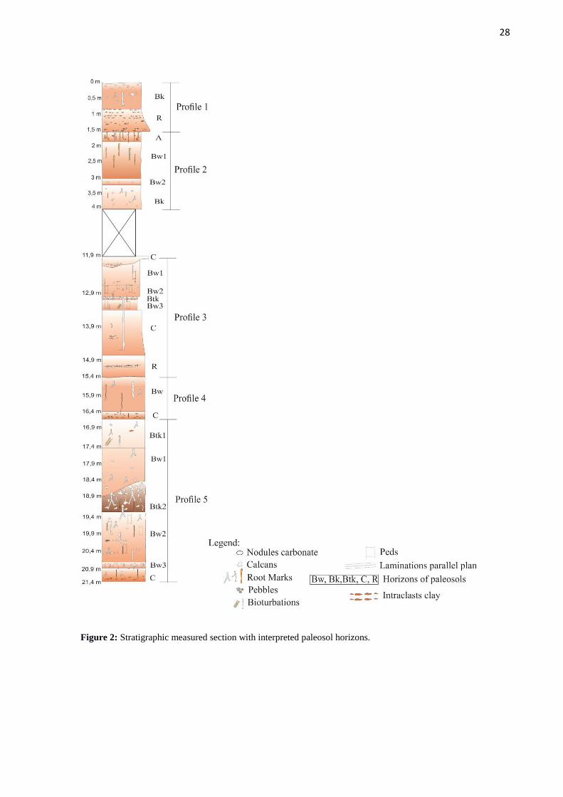
Five paleosol profiles were described: Profile 1 with Bk and R horizons; Profile 2
with the A, Bw1, Bw2 and Bk horizons; Profile 3, divided between Bw1, Bw2, Btk, Bw3, C
and R; Profile 4, divided between the Bw and C; Profile 5 horizons, divided between Btk1,
Bw1, Btk2, Bw2, Bk and C (Figure 2).
28
Figure 2: Stratigraphic measured section with interpreted paleosol horizons.
29
The top and bottom of the profiles are characterized by planar erosive surfaces
identifiable by the presence above this surface of intraformational mudstone and small
pebbles of metamorphic or magmatic rocks. Overall, the paleosol profiles consist of fine to
medium-grained sandstone in upper part of the profile and coarse-grained sandstone in the
lower portion. In C horizons, it is possible observe remains of sedimentary structures that
consist in weakly horizontal laminations and horizontal accumulations of intraformational
mudstone clasts. R horizon is the original parent material, is below described as deposit.
Description of horizons
The horizon A consists of medium- to fine-grained sandstone, moderate- to well-
sorted. Predominant color is orange (2,5YR6/6), however there are mottling bright reddish
brown (2,5YR5/8). There is no reaction in the test with 10% Hcl. The horizon A contain often
tubular structures (rizotubules), vertical and 0.5 m length, filled with sandstone of different
particle size. These marks are very common between 0-0.3 m. Some branching tubules show,
the diameter is generally about 0.2 m and tapering down with a 5-7 mm diameter, filled
sandstone is light gray with black spots linked to manganese, thick, poorly sorted and small
pebbles (Figure 3 A).
The Bw horizons consist of medium- to fine-grained, moderately sorted sandstone.
The sandstone grains show apparent surface microtexture to wind transport. The predominant
color is orange (2,5YR6/8) and reddish brown (2,5YR5/8). Roots marks are present, but not
so abundat as in A horizon. The transition from the lower limit is 60 mm (gradual) and is
characterized by an increase of cementation (Figure 3 B).

30
Figure 3: A - roots marks vertically with ramifications, coin with 20 mm in diameter. B - Peds separated by
calcans, horizon structures Bw, coin with 21 mm in diameter.
The horizon Bk consists of fine- to medium-grained sandstone, cemented and
moderately sorted. The predominant color is orange (2.5YR6/6). The upper contact has
transition 20-30 mm (abrupt). The nodules are widespread on the surface of the vertical
section by up to 20%. The reaction with HCl produces bubbles to 4 mm demonstrating high
content of calcium carbonate. The lower limit transition has around 60-70 mm (gradual),
indicated by the progressive reduction of nodules. The nodules have size ranging from 10 mm
to 30 mm and irregular shape. Some nodules show dark spots of manganese (Figure 4 A ).
Reddish orange surfaces (2.5YR7/3) are present and may indicate calcans. Small radial
structures recognized as rizotubules (coated calcite esparítica) are frequent (Figure 4 A and
B).
Btk horizons is light reddish orange (2,5YR7/4) with light gray (5Y8/1) mottling, that
can indicate conditions of temporary stagnation of water within the soil. This horizon is
characterized by higher values molar ratio of Al203/Si02 (clay content) if compared with the
adjacent horizons, probably indicating accumulation of clay (Figure 4 C and D).

31
Figure 4: A - Upper limit of Bk horizon with carbonate nodules. B - Root marks and calcans in horizon Bk. C –
Horizon Btk, root marks cylindrical and vertical gray with greenish halo, filled by cemented sand and calcium
carbonate and blocky structures. D - Horizonte Btk, gradual transition to the higher range of carbonate nodules.
Coin with 20 mm in diameter.
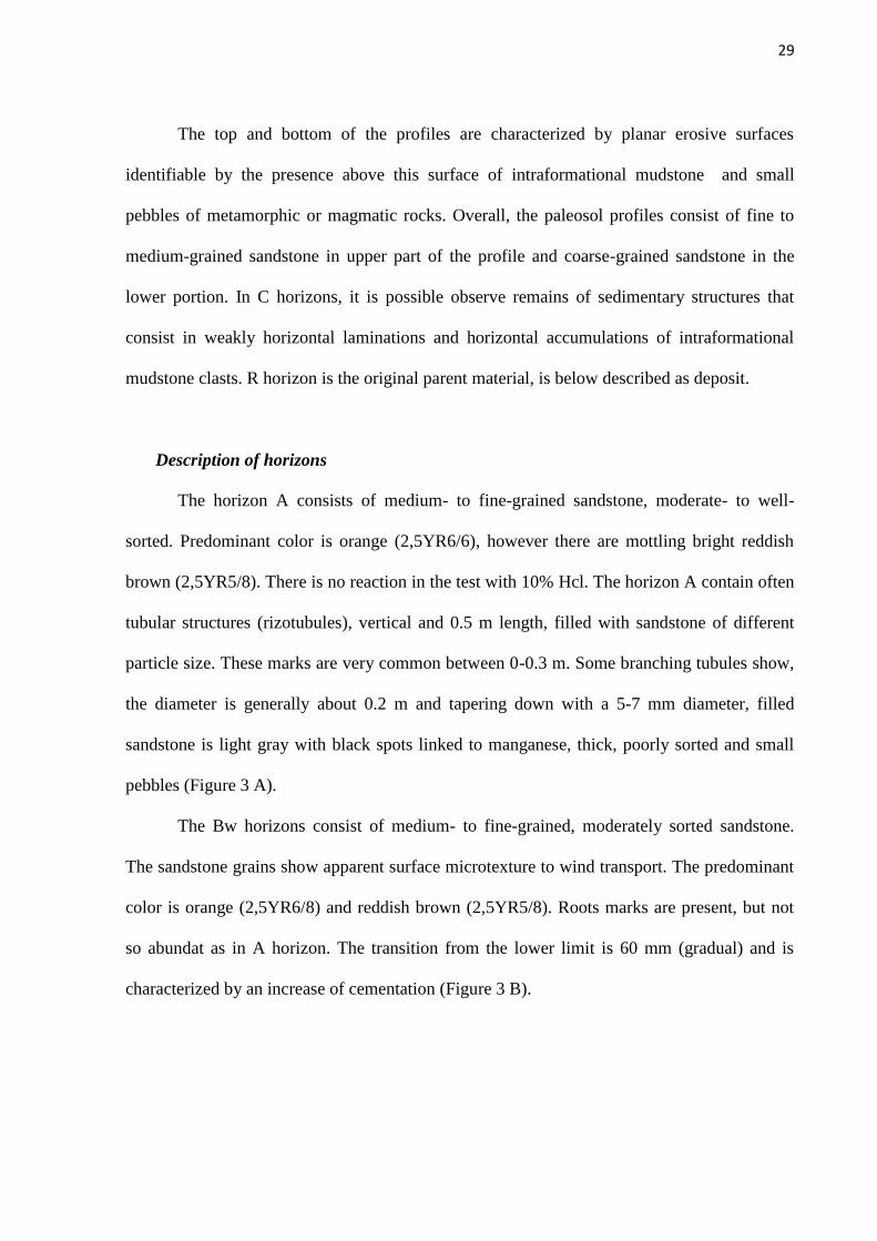
C horizons is constituted of poorly defined planar laminations and horizontal
alignment of mudstone intraclasts; they testify original sedimentary structures of the parent
material. The horizon consists of medium to fine sandstones. The color is orange-red (10R
6/6) and mudstone intraclast are present. These clasts ranging from medium- to coarse-
grained and has bright reddish brown color (2.5YR5/8). There is HCl reaction, however, the
reaction is mild, with smaller bubbles than 1 mm. Uncommon carbonate nodules occur. The
transition to the lower horizon has less than 2 cm (abrupt) (Figure 5).
32
Figure 5: Horizon C, details for mark to tap roots. Scale - Jacob staff: 1.5 m
Geochemistry
As in current soils in paleosols geochemical analyzes are also used, however it is
important to highlight some considerations. In paleosols there is some difficulty in performing
analysis of cation exchange or base saturation, because the base saturation and capacity of
cation exchange soil are not preserved in paleosols and are substantially altered shortly after
burial (Retallack 1991, 2001). However, the chemical composition of some of the more
resistant mineral paleosols resists to the diagenetic processes and even the metamorphic
changes (Barrientos and Selverstone 1987).
When is the burial of paleosols, soon results in compression and the spaces between
the pores may be changed or lost. The organisms and the water are compressed by the weight
of the overlying layers. The compaction of the loose material of the original soil could create
a standard surface slickensides, similar to slickensides produced by expansion and contraction
of clay soils of seasonally dry climates (Paton 1974, Gray and Nickelsen 1989).

33
The use of larger elements geochemical is intended to identify individual indices
which quantify all of the weathering processes. Nesbitt and Young (1982) proposed the
"chemical index of alteration" (CIA) having a molar ratio of CIA 100 X (Al2O3 / (Al2O3 + CaO
+ Na2O + K2O)), where each of the elemental concentrations is converted into moles. CIA is a
measure of the resistance of feldspar minerals and its hydration to form clay minerals. As the
clay content increases Al2O3 should also increase as CaO, K2O and Na2O contents should
decrease, thus leading to higher values of CIA.
Six analyzes of molecular ratios were calculated to evaluate the degree of chemical
weathering of paleosols and check which pedogenetic processes were more important. In
addition, these indexes have been used to separate the horizons paleosols (Sheldon and Tabor
2009, Retallack 2001, Sheldon et al. 2002).
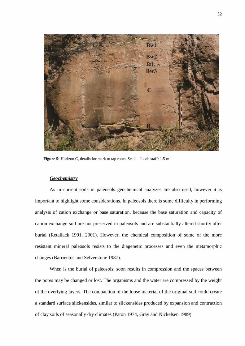
Bases / alumina ratios ((CaO + MgO + Na2O + K2O) / Al2O3) can be used to quantify
the extent of hydrolysis (Retallack 2001). In Figure 6 the accumulation indicates some major
points, it demonstrates greater amount of base as compared with aluminum, this is because the
basic elements (CaO, MgO, Na2O and K2O) have greater ease to being leached when
compared with aluminum and its preservation may indicate the accumulation of bases. Still in
Figure 6, in the hydrolysis, while the other points are low it may indicate a decrease of bases
compared to aluminum showing that hears a higher hydrolysis rate in the system. Comparing
this relationship with the CIA is observed that the proportions between both appear in reverse.
The Btk horizontal profile 3 shows the minimum CIA value around 4, leaching with a value
close to 1, and the hydrolysis around 39, so you can see the high levels of hydrolysis
representing the accumulation of bases, low leaching and CIA highlighting the few chemical
changes in this horizon.
Leaching was quantified using the links Ba/Sr and Rb/Sr. Strontium is significantly
more soluble than barium and rubidium thus higher values are expected in more leached

34
horizons (Retallack 2001). Leaching occurs in reverse order as compared to the hydrolysis;
consequently higher leaching values are expected to decrease the basic loss ratios (CaO +
MgO + Na2O + K2O / Al2O3).
The clay content was quantified using the ratio Al2O3 / SiO2. The clay content can be
used in paleosols for confirming Bt horizons. The analyzed profiles, the clay shows a
proportion with calcification, which suggests horizons such as Btk.
Calcification ((CaO + MgO) / Al2O3) also correlates with the preservation ratio of the
bases shown in hydrolysis. Such calcification is characteristic of pedogenic horizons enriched
in calcium carbonate occurring in areas where the primary ion source is the wind transport
through the dust (Goudie 1983, Machette 1985).
The provenance was calculated by the proportion of TiO2 / Al2O3 and is used as a TiO2
content indicator can be quite variable among different types of rocks as well as the Al2O3
concentration is relatively constant (e.g., granite, basalt vs.; Li, 2000). Both TiO2 as Al2O3 are
relatively immobile, the proportion of both must remain constant during pedogenesis. The
analyzed values can be observed that there is a wide variation in the results of the proportion
TiO2/Al2O3, thus indicating the origin of the same type of parental material, consisting of
felsic rocks.
35
Figure 6: Analyzes with data from chemical elements. Hydrolysis (CaO+MgO+Na2O+K2O/(Al2O3)). Clay
Formation (Al2O3/SiO2). Calcification (CaO+MgO/Al2O3). Provenance (TiO2/Al2O3). CIA 100X (Al2O3 /(Al2O3
+ CaO + Na2O + K2O))
36
Interpretation of horizons
The horizon A can be recognized for abundance of roots traces and bioturbation. The
horizon A is not cemented, probably due to leaching of calcium carbonate which precipitated
in lower horizon (Bw or Btk). Uncommon preservation of A horizon is due to the easy
erosion that it suffered by unchannelized flows, as below described. More dense vegetal
cover and low energy of the unconfined subaqueous flows can be at origin of local
preservation of A horizon.
In Bw horizon poor defined prismatic structures, separated by thin cuticles carbonate
(calcans) can be observed. Bw is a cambic horizon, a horizon where the pedogenetic alteration
of the parent material is sufficient to differentiate horizons, but not enough to define other
more developed horizons as Bk or Bt.
Bk horizons were identified only in two cases. They are individualized by higher
concentration of calcium carbonate relatively to the other horizons. This higher content is
indicated by the presence of calcium carbonate nodules and chemical analysis, which show
peaks of calcification in correspondence of Bk horizon.
Btk horizon. Three horizons have been described. This horizon is characterized by
values mole ratio of Al2O3 / SiO2 (clay content) higher compared with the adjacent horizons
indicating accumulation of clay, ash content is too high, the highest rate of clay is what
differentiates this horizon compared to Bk horizon.
Horizon C. have been reported three C. Overall, C horizon is identified and classified
to have some pedogenetic features, but not enough to define them as horizons A or B. It also
show original some features of parental material.

37
Parental material
Molecular ratios of TiO2/Al2O3 have values of 0.07 to 0.15. Thus they indicate that the
source of these sandstones is felsic rocks (Sheldon and Tabor 2009). These values are similar
for all paleosol profiles indicating no change of the parent material along the studied section.
Deposits
In paleosol profiles the deposits are described as horizons R. Deposits are constituted
of conglomeratic sandstone with contain a significant amount of muddy intraclasts. They are
characterized by plane parallel laminations and horizontal alignment of muddy intraclasts.
The deposits are partially preserved in the lower portion of each paleosol profile. They
consist of conglomeratic sandstone. The sandstones are medium- to coarse-grained and the
conglomerates are constituted of intraformational mudstone clasts, 1 to 60 mm across, angular
or sub-rounded, flattened or elliptical in shape (Figure 7). Some calcareous nodules can be
present amongst the as intraclasts (pedorelicts). Extraformational clasts are constituted of
quartzite and granitic rocks, they are rounded or subrounded and up to 50 mm across. There
are more than 60 m in lateral extension; the bottom is sharp and erosive, characterized by
small scours, the top is transitional to medium-grained sandstone of C horizon, sandstones
with planar parallel laminations and horizontal alignments of pebbles are the only evident
sedimentary structure.
38
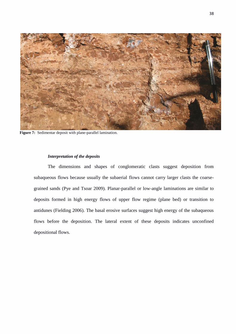
Figure 7: Sedimentar deposit with plane-parallel lamination.
Interpretation of the deposits
The dimensions and shapes of conglomeratic clasts suggest deposition from
subaqueous flows because usually the subaerial flows cannot carry larger clasts the coarse-
grained sands (Pye and Tsoar 2009). Planar-parallel or low-angle laminations are similar to
deposits formed in high energy flows of upper flow regime (plane bed) or transition to
antidunes (Fielding 2006). The basal erosive surfaces suggest high energy of the subaqueous
flows before the deposition. The lateral extent of these deposits indicates unconfined
depositional flows.
39
DISCUSSION
The alternation between sedimentary deposits and topographic stability were the main control
factors of the development paleopedogenetics. The genesis of the five paleosol profiles is controlled
by unconfined depositional flows by catastrophic flooding phenomena occurring periodically, these
flows transporting coarse sandstone, clay intraclasts, pedorelicts and pebles. After the deposition when
it happened the stability of the topographic surface, the pedogenesis processes began. However there
were no enough time to change the entire deposit, this is demonstrated in C and R horizons.
Calcium carbonate indicate a climatic semiarid because these carbonate it is not water table
but pedogenetic, root marks mains in horizon A indicate the sparse vegetation, usually when erosion
occurs in A horizons, for being the most superficial horizons are destroyed, probably this vegetation
probably this vegetation contributes to its preservation.
In section profiles 1 and 4 has only two horizons, while the other profiles are more developed,
this can represent less exposure time in the atmosphere of the profiles 1 and 4 compared to others, or
by increased sediment yield or the rate of greater erosion, or a more unstable surface, since the other
profiles may represent greater development time and higher environmental stability.
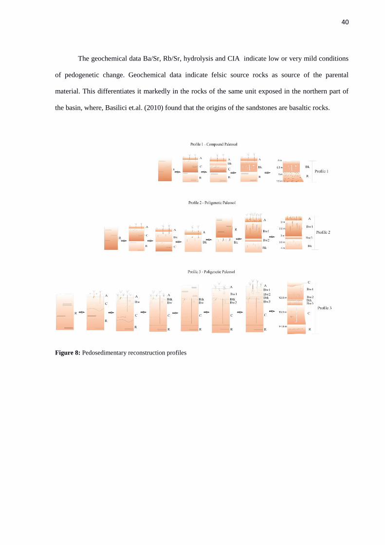
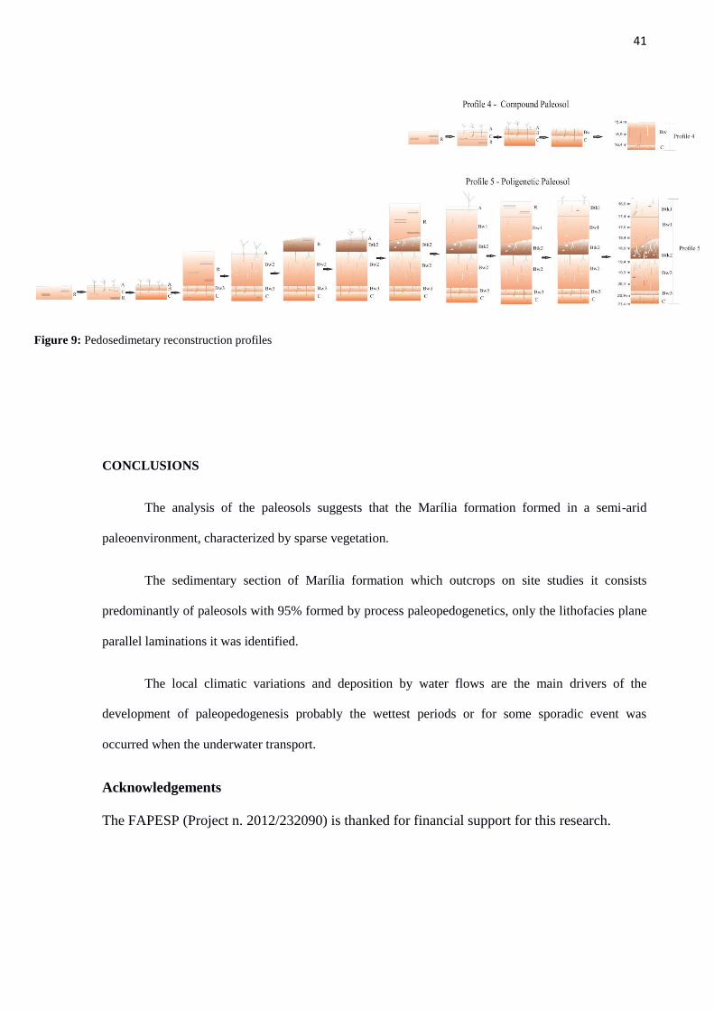
The types of paleosols described in profiles 1 and 4 are classified as compound, these types of
paleosols are formed when the sedimentary deposit is relatively rapid and few erosion, occurs the
process of pedogenesis but does not change the entire deposit (Marriott and Wright 1993). Can
preserve in its sedimentary structures bases as well as demonstrates the most evident form the erosive
surfaces (Figures 8 and 9)
In the profiles 2, 3 and 5 the paleosols are classifies with polygenetic paleosols, in this type of
paleosols there is enough time and weather conditions that can enable pedogenetic development
throughout the deposit and because the new sedimentation and pedogenesis the horizon of a new
profile can override the horizon of an older profile, this may also indicate a greater interruption in the
sedimentation (Figures 8 and 9).
40
The geochemical data Ba/Sr, Rb/Sr, hydrolysis and CIA indicate low or very mild conditions
of pedogenetic change. Geochemical data indicate felsic source rocks as source of the parental
material. This differentiates it markedly in the rocks of the same unit exposed in the northern part of
the basin, where, Basilici et.al. (2010) found that the origins of the sandstones are basaltic rocks.
Figure 8: Pedosedimentary reconstruction profiles
41
Figure 9: Pedosedimetary reconstruction profiles
CONCLUSIONS
The analysis of the paleosols suggests that the Marília formation formed in a semi-arid
paleoenvironment, characterized by sparse vegetation.
The sedimentary section of Marília formation which outcrops on site studies it consists
predominantly of paleosols with 95% formed by process paleopedogenetics, only the lithofacies plane
parallel laminations it was identified.
The local climatic variations and deposition by water flows are the main drivers of the
development of paleopedogenesis probably the wettest periods or for some sporadic event was
occurred when the underwater transport.
Acknowledgements
The FAPESP (Project n. 2012/232090) is thanked for financial support for this research.

42
8. CONCLUSÃO
A gênese dos cinco perfis de paleossolos apresentados no artigo, assim como os perfis
descritos no trabalho são controlados por fluxos deposicionais não confinados que ocorriam
periodicamente, esses fluxos transportavam areia grossa, clastos, intraclastos de argila e
pedorelictos, uma vez depositado e estabilizado iniciava-se o processo de pedogênese, no
entanto não houve tempo suficiente para alterar todo o depósito, isso é demonstrado nos
horizontes C e R.
As variações climáticas locais e a deposição por fluxos subaquáticos são os principais
controladores do desenvolvimento da paleopedogênese, provavelmente nos períodos mais
úmidos ou por algum evento esporádico era quando ocorria o transporte subaquático. A
atividade eólica também estava ativa nos intervalos dos depósitos subaquáticos retrabalhando
os materiais depositados durante os períodos mais áridos.
Com as análises dos paleossolos é possível observar os ciclos de alta frequência
caracterizados por deposição de sedimentos e estabilidade da paisagem por determinados
períodos.

43
9. REFERÊNCIAS
Barrientos, X., Selvestone, 1. 1987. Metamorphosed soils as stratigraphic indicators in deformed
terranes: an example from the eastern Alps. Geology 1 5 : 841- 44
Basilici, G., Dal Bó, P.F.F., Ladeira, F.S.B., 2009. Climate-induced sediment-palaeosol cycles
in a Late Cretaceous dry aeolian sand sheet: Marília Formation (North-West Bauru Basin,
Brazil). Sedimentology 56, 1876–1904.
Basilici., Dal’ Bó, P.F.F. 2010. Anatomy and controlling factors of a Late Cretaceous Aeolian
san sheet: The Marília and Adamantina formations, NW Bauru Basin, Brazil. Sedimentary
Geology. p. 71-93.
Batezelli, A. 2015. Continental systems tracts of the Brazilian Cretaceous Bauru Basin and
their relationship with the tectonic and climatic evolution of South America. Basin Research.
p. 1-25.
Bertini, R.J., Marshall, L.G., Gayet, M., Brito, P. 1993. Vertebrate faunas from the
Adamantina and Marilia formations (Upper Bauru Group, Late Cretaceous, Brazil). Neues
Jahrbuch fur Geologie und Paleontologie. Abhandlungen 188 (1), p. 71–101.
Bull, W.B. 1991. Geomorphic Responses to Climate Change. Oxford University
Press, New York. 506 pp.
Catt, J.A. 1990. Paleopedology manual. Quaternary International, 6. 95 p.
Dal' Bó, P.F.F., Basilici, G., Angelica, R.S., Ladeira, F.S.B. 2009. Paleoclimatic
interpretations from pedogenic calcretes in a Maastrichtian semi-arid eolian sand-sheet
palaeoenvironment: Marilia Formation (Bauru Basin, southeastern Brazil). Cretaceous
Research 30, p. 659–675.
Dal' Bó, P.F.F., Basilici, G., Angelica, R.S. 2010. Factor of paleosol formation in a Late
Cretaceous eolian sand sheet paleoenvironment, Marília Formation, Southeastern Brazil. 30,
p. 659–675. Palaeogeogr. Palaeoclimatol. Palaeoecol. doi:10.1016/j.palaeo.2010.04.021
Dias-Brito, D., Musacchio, E.A., Castro, J.C. de., Maranhão, M.S., Suarez, J.M., Rodrigues,
R. 2001. Grupo Bauru: uma unidade continental do Cretáceo no Brasil – concepções baseadas
em dados micropaleontológicos, isotópicos e estratigráficos. Revue de Paléobiologie 20 (1),
245-304.
Fernandes, L. A., Coimbra, A. M. 1996. A Bacia Bauru (Cretáceo Superior, Brasil). Anais da
Academia Brasileira de Ciências, Rio de Janeiro. p. 195-205.

44
Fernandes, L.A., Coimbra, A.M. 2000. Revisão estratigráfica da parte oriental da Bacia Bauru
(Neocretáceo). Revista Brasileira de Geociências 30, 717-728.
Fernandes, L.A., Ribeiro, C.M.M. 2015. Evoluntion and palaeoenovironments of the Bauru
Basin (Upper Cretaceous, Brazil). Journal of South American Earth Sciences 61. p. 71-90.
Fielding, C. R. 2006. Upper flow regime sheets, lenses and scour fills: Extending the range of
architectural elements for fluvial sediment bodies. Sedimentary Geology, 190, 227–240.
Gile, L.H., Peterson, F.F., Grossman, R.B. 1966. Morphological and genetic sequences of
carbonate accumulation in desert soils. Soil Sci., 101, 347–360.
Gray, M. B., Nickelsen, R. P. 1989. Pedogenic slickensides, indicators of strain and
deformation processes in red bed sequences of the Appalachian foreland. Geology 1 7 : 72-
75.
Goudie, A.S., 1983. Calcrete. In: Goudie, A.S., Pye, K. (Eds.), Chemical Sediments and
Geomorphology: Precipitates and Residual in Near-Surface Environment. Academic Press,
London, pp. 93–131.
Kidder, D.L., Worsley, T. R. 2010. Phanerozoic large igneous provinces (LIPs), HEATT
(Haline Euxinic Acidic Thermal Transgression) episodes and mass extinctions.
Palaeogeography, Palaeoclimatology, Palaeoecology, 295, 162-191, doi: 10.1016/j.palaeo.
Kidder, D.L., Worsley, T. R. 2012. Human-induced hothouse climate. GSA Today, 22, 4-11.
Klappa, C.F. 1980. Rhizoliths in terrestrial carbonates: classification, recognition, genesis,
and significance: Sedimentology, v. 26, p. 613–629.
Kraus, M. 1999. Paleosols in clastic sedimentary rocks: their geologic applications. Earth
Science Reviews, v. 4.
Li, Y.-H., 2000. A Compendium of Geochemistry. Princeton University Press, Princeton.475 pp.
Machette, N.M. 1985. Calcic soils of the southwestern United States. In: Soils and Quaternary
Geology of the Southwestern United States (Ed. D.L. Weide), Geol. Soc. Am. Spec.Pap., 203,
10–21.
Nesbit, H.W., Young, G.M., 1982. Early Proterozoic climates and plate motions inferred from
major element chemistry of lutites. Nature 299, 715–717.
North, C.P., Davidson, S.K. 2012. Unconfined alluvial flow processes: Recognition and
interpretation of their deposits, and the significance for palaeogeographic reconstruction.
Earth-Science Reviews, 111,199–223.

45
Paton, T. R. 1974. Origin and terminology for gilgai in Australia. Geoderma l l : 22 1 - 42
Pye, K., Tsoar, H. 2009. Aeolian Sand and Sand Dunes. Springer, Berlin, 476 pp
Retallack, G.J. 1991. Miocene Palesols and Ape Habitats of Pakistan and Kenya. Oxford University
Press, NewYork.
Retallack, G.J. 1994. A pedotype approach to latest Cretaceous and earliest Tertiary paleosols
in eastern Montana. Bulletin of the Geological Society of America, 106, 1377-1397.
Retallack, G.J. 2001. Soils of the past: an introduction to paleopedology. Allen and Unwin,
London, 520 pp.
Riccomini, C. 1997. Arcabouço estrutural e aspectos do tectonismo gerador e deformador da
Bacia Bauru no estado de São Paulo. Revista Brasileira de Geociências 27 (2), 153-162.
Ruellan, A. 1971 . The history of soils: some problems of definition and interpretation. In:
Yaalon, D.H. (Ed.). Paleopedology: origin, nature and dating of paleosols. International
Society of Soil Science and Israel University Press, Jerusalem, pp. 03-13.
Santucci R.M., Bertini R.J. 2001. Distribuição Paleogeográfica e Biocronológica dos
Titanossauros (Saurishia, Sauropoda) do Grupo Bauru, Cretáceo Superior do Sudeste
Brasileiro. Revista Brasileira Geociências 31, p. 307-315.
Sheldon, N.D., Retallack, G.J., Tanaka,S. 2002. Geochemical climofunctions from North
America soils and application to paleosols across the Eocene-Oligocene boundary in Oregan.
Journal of Geology 110, 687-696.
Sheldon, N.D. Tabor, N.J. 2009. Quantitative paleoenvironmental and paleoclimatic
reconstruction using paleosols. Earth-Science Reviews, v. 95, p. 1-52.
Soares, P.C., Landim, P.M.B., Fulfaro, V.J., Neto, A.F.S. 1980. Ensaio de caracterização
estratigráfica do Cretáceo no Estado de São Paulo: Grupo Bauru. Rev. Brasil. Geociências,
10, 177–185.
Soil Survey Staff. 1999. Soil taxonomy. Handbook, U.S. Department of Agriculture 436, 869
pp.

46
10. GLOSSÁRIO
Bioturbação:
Marcas de organismos (raízes, animais)
preservados em paleossolos.
Calcans: Manchas esbranquiçadas provocadas
pela precipitação de carbonato de cálcio.
Estrutura do solo (agregados, peds): Organização das partículas dos solos (blocos, prismática, granular), tamanho e grau de desenvolvimento.
Estrutura incipiente:
Estrutura do solo pouco desenvolvida, de
difícil identificação.
Horizonte: Diferentes níveis de um perfil de solo, caracterizados por modificação da cor, textura, estrutura, processo de intemperização.
Horizonte A:
Horizonte superficial, possui cor mais
escura pela influência da decomposição da
matéria orgânica, e com grande atividade
biológica.
Horizonte B:
Horizonte mais desenvolvido, com
estruturas, cor, textura e cerosidade mais
evidentes, é o horizonte mais adequado
para classificar o tipo de solo.
Horizonte C:
Horizonte que preserva algumas estruturas
da rocha, porém sofreu o processo de
pedogênese.
Horizonte R: Material de origem. Rocha sem sofrer o
processo pedogenético.
Horizonte duripan: horizonte subsuperficial
fortemente cimentado por sílica.
Mosqueamento (mottling):
Manchas esbranquiçadas provocadas pela
redução do ferro.
Nódulos carbonáticos:
Concentração de carbonato de cálcio em
formas de nódulos.
Paleossolos compostos:
Paleossolos em que os processos
pedogenéticos não são capazes de alterar todo
o material de origem, preservando estruturas
da rocha nos horizontes inferiores.
Paleossolos Poligenéticos:
Paleossolos com condições suficientes para
permitir o desenvolvimento pedogenético de
todo o depósito não preservando estruturas do
material de origem.
Superfície de fricção (slickensides):
Estrias no solo provocado pela expansão e
contração da argila. Pode indicar
alternância entre ambiente úmido e seco.
Paleossolos truncados:
A remoção dos horizontes superiores de
um paleossolo pode retirar totalmente o
horizonte B, o material restante atua como
material de origem para um novo
desenvolvimento pedogenético.

47
11. ANEXO
Artigo 2
STRATIGRAPHIC AND PALAEOENVIRONMENTAL CONTEXT OF A PALAEOSOL
DOMINATED SEMIARID FLUVIAL DISTRIBUTARY SYSTEM (BAURU GROUP,
UPPER CRETACEOUS, SE BRAZIL)
STRATIGRAPHIC AND PALAEOENVIRONMENTAL CONTEXT OF A PALAEOSOL-1
DOMINATED SEMIARID FLUVIAL DISTRIBUTARY SYSTEM (BAURU GROUP, UPPER 2
CRETACEOUS, SE BRAZIL) 3
Giorgio Basilici1,2 , Patrick Führ Dal' Bo3 , Emerson Ferreira1 4
1 Department of Geology and Natural Resources, Institute of Geosciences, State University of 5
Campinas, 13083‐870, Campinas (SP), Brazil. 6
2 Centro Regional de Investigaciones Científicas y Transferencia Tecnológica/CONICET, 7
Argentina. 8
3 Department of Geology, Institute of Geosciences, Federal University of Rio de Janeiro, Rio de 9
Janeiro (RJ), Brazil. 10
11
ABSTRACT 12
The stratigraphic and sedimentological knowledge of the Bauru Group (Upper Cretaceous, SE 13
Brazil) are still broadly insufficient and controversial. This contrasts with a great amount of 14
palaeontological studies. A detailed sedimentological and palaeopedological study allowed to 15
interpret the south-eastern portion of the Bauru Group according to the model of fluvial 16
distributary system. This work has two objectives: (1) to give detailed information on the 17
sedimentological and stratigraphic features of the SE portion of the Bauru Group to support 18
biostratigraphical, taphonomic and palaeoecological studies; (2) to include palaeosols into the 19
model of fluvial distributary system. In south-eastern portion of the Bauru Group three genetic 20
stratigraphic units were described and interpreted, here informally called lower, intermediate and 21
upper units. The lower unit is constituted of muddy sandstone salt flat deposits and sandstone 22
sheet deltas deposits and is interpreted as basinal part of a fluvial distributary system. The 23
intermediate unit is formed of sand-filled ribbon channel and sandy sheet-shaped beds, 24
suggesting distal or medial portion of a fluvial distributary system. The upper unit is almost 25

completely constituted of palaeosols and does not match with the present models of fluvial 26
distributary system. Preserved features of sedimentary structures suggest that the parent material 27
was formed by catastrophic unconfined flows. Moderately developed palaeosols (Inceptisols) 28
testify pauses of sedimentation of the order of 104 y, probably linked with a climate aridification 29
that decreased the sedimentary input due to the retreat of the fluvial system. Thus, the upper unit 30
deposited in more distal portion of a fluvial distributary system, where catastrophic unconfined 31
flows, which occurred with recurrence time of 104 y, were almost completely pedogenised during 32
the interruption of sedimentation. Including palaeosols into the fluvial distributary system modified 33
the architectural structure of this model. 34
35
Key Words: fluvial distributary system, semiarid depositional environment, palaeosols, Late 36
Cretaceous, Bauru Group. 37
38
1. INTRODUCTION 39
In arid or semiarid climate fluvial systems can disappear before to reach a larger river or a 40
standing body of water. This type of fluvial systems, called fluvial distributary system or terminal 41
fan or terminal fluvial fan, was firstly described by Mukerji (1976) and Friend (1978) and 42
subsequently amplified and modified by Tunbridge (1984), Kelly and Olsen (1993), Nichols 43
(2005), Nichols and Fisher (2007), Saéz et al. (2007), North and Warwick (2007) and Cain and 44
Mountney (2009). This depositional system is subdivided in three main portions (Kelly and Olsen, 45
1993): proximal, medial and distal. The proximal part is characterised by a main feeder channel, 46
whose lateral migrations and avulsions generate a lateral and vertical amalgamated channel body 47
complex with almost absent overbank deposits. The medial portion shows distributary channels, 48
probably without coeval flow (North and Warwick, 2007; Cain and Mountney, 2009), and it forms 49
a geological body with minor channel deposits surrounded by interchannel deposits. The distal 50

portion is characterised by unconfined deposits originated at the termination of the channels and 51
few channel bodies. Depending on the climate and morphological conditions the basinal zone of 52
this system can be characterised by ephemeral lakes or aeolian deposits (Nichols, 2005). In 53
place of terminal fan or terminal fluvial fan, Nichols and Fisher (2007) proposed to use the more 54
general term of "fluvial distributary system", which describes a river system with fan shape, 55
decreasing discharge downwards, and distal area constituted of terminal splays when a lake is 56
absent or deltas when the lake is present. This term is used in this work. 57
The depositional models of fluvial distributary systems take in account only sediments, whereas 58
palaeosols are rarely cited, often as portion of the interchannel deposits or as fragments 59
(pedorelicts) contained within the channel deposits (Tunbridge, 1984; Nichols and Fisher, 2007; 60
Fisher et al., 2007; Cain and Mountney, 2009). In this paper, we propose to apply the model of 61
fluvial distributary system to explain the stratigraphic organisation and the depositional 62
paleoenvironment of the south-eastern portion of the Bauru Group. However, differently to the 63
usual models of fluvial distributary system, we considered in our model analysis the palaeosols 64
and their relationships with the deposits. 65
The stratigraphic organisation of the Bauru Group is complex and debated since its first studies 66
(Mezzalira and Arruda, 1965; Soares et al., 1980; Fernandes and Coimbra, 2000; Paula e Silva et 67
al., 2009). Many reasons make complicated the stratigraphic resolution of this sedimentary basin: 68
(1) the lithologic featureless of the succession, which is in general formed of reddish brown 69
sandstone, with relatively uncommon sedimentary structures; (2) the huge dimension of the 70
basin, which exceeds 350,000 km2; (3) the absence of clear biostratigraphic or geochronological 71
data; (4) the abundance of multiple palaeosol profiles, which, on average, are c.60% of the 72
thickness of the sedimentary succession (Basilici et al., 2009); (5) the large scale lateral 73
variations of sedimentological and palaeopedological features; (6) the previous exclusive use of 74
lithostratigraphic criteria to distinguish the different units. These difficulties generated contrasting 75

interpretations of the stratigraphy of this group (Fernandes and Coimbra, 2000; Paula e Silva et 76
al., 2009; Fernandes and Ribeiro, 2015; Batezelli, 2015), which in the field result in a huge 77
difficulty to distinguish the different lithostratigraphic units. Being the Bauru Basin an important 78
sedimentary succession containing a rich and well-preserved Cretaceous fauna association, this 79
difficulty is realised above all by palaeontologists, which complain that the exact definition of the 80
units where the fossils were found is not always an easy task. 81
In recent years, punctual works on palaeosols and relationships palaeosols/deposits have been 82
realised in northern and south-eastern portions of the Bauru Basin, in an area of approximately 83
13,000 km2 (Fig. 1), permitting the collection of many information on the stratigraphy of this basin 84
(Fernandes and Basilici, 2009; Dal' Bó et al., 2009; Basilici et al., 2009; Dal' Bó et al., 2010; 85
Basilici et al., 2010; Basilici et al., 2012). The study area coincides with the sites where the main 86
lithostratigraphic units of the Bauru Basin were originally defined (Soares et al., 1980; Fernandes 87
and Coimbra, 2000). 88
89
2. STUDY AREA, GEOLOGIC AND STRATIGRAPHIC SETTING OF THE BAURU GROUP 90
Small and sporadic outcrops, few previous detailed sedimentological studies and the huge 91
extension of the Bauru Group make deceptive to produce presently a clear framework of the 92
stratigraphic organisation and sedimentary evolution of the entire unit. For these reasons, this 93
work is limited to the analysis of the south-eastern portion of the Bauru Group (Fig. 1). 94
The sedimentary succession of this basin is developed above one of largest basalt effusion of the 95
earth history, the Serra Geral Formation, due to the separation of South America and Africa. The 96
succession reaches a maximum thickness of around 300 m for a period comprised between 97
Coniacian to Maastrichtian (Fernandes and Ribeiro, 2015) or Aptian to Maastrichtian (Batezelli, 98
2015). The succession is constituted of fine- to medium grained sandstone with uncommon 99
conglomerate beds (less than 5% of the thickness), which are diffused in northern part of the 100
basin, and sandy mudstone (less than 2% of the thickness). Overall, two groups are 101
distinguished: Caiuá and Bauru groups, which are distributed on the western and eastern part of 102
the basin, respectively (Fig. 2A). The Figures 2B and 2C represent two different stratigraphy 103
interpretations of the Bauru Basin. These interpretations show a consistent quantity of 104
lithostratigraphic units, mostly characterised by interbedded and undefined boundaries, which 105
commonly make unreliable their identification in the field. The cited authors agree with the 106
interpretation of the Caiuá Group deposited in erg system, although they disagree on its chrono- 107
and lithostratigraphic position (Fig. 2B and C). The sedimentological interpretation of the Bauru 108
Group is unclear and partially conflicting. Fernandes and Ribeiro (2015) interpreted the Araçatuba 109
Formation formed in marshland areas, the Vale do Rio do Peixe Formation (or Adamantina 110
Formation, according to Batezelli, 2015) and Echaporã Member of Marília Formation deposited in 111
aeolian sand sheet, and Serra da Galga and Ponte Alta members of Marília Formation formed in 112
distal part of alluvial fan systems. Batezelli (2015) interprets the Araçatuba Formation as lake 113
system, the Adamantina Formation as fluvial systems and the Marília Formation as alluvial fan 114
deposits. Unfortunately, these interpretations did not give an adequate consideration to the 115
palaeosols, which actually constitute on average 60% of the thickness of the Bauru Group. 116
117
3. METHODS 118
In south-eastern portion of the Bauru Group we measured 15 detailed stratigraphic sections for a 119
total thickness of 161 m. Several tens of outcrops were observed to better define the lithofacies 120
and palaeosols of the sedimentary succession. Directly in the area of the Serra de Echaporã 121
(Marília) (Fig.1) we measured a general stratigraphic section of 245 m taking advantage of all 122
possible the outcrops. Methods of analyses and study of deposits and palaeosols has been 123
diversified. In the field, the palaeosols were identified for presence of root traces (rhizoliths), 124
colour, pedogenic structures, parent material, nodules, mottles, calcium carbonate concentration, 125

horizons and absence of sedimentary structures. Forty-five palaeosol profiles were analyzed in 126
detail, for a total 68 m of thickness. In these palaeosol profiles 46 samples were collected from 127
palaeosol horizons. Analyses of the samples were performed for classifying and defining the 128
paleoenvironmental features of the palaeosols, the provenance of parent material and deposits, 129
and the depositional mechanism of the parent material. Field estimation of abundance of calcium 130
carbonate and boundary distinctness of the palaeosol horizons were done using the 131
recommendations of Hodgson (1976). When the horizon thickness was used to calculate time of 132
development the field values were corrected by a compaction factor defined by the compaction 133
equation and relative tables of Sheldon and Retallack (2001). In the laboratory, geochemical, 134
petrographic and microtextural analyses were realized. Geochemical analyses consisted in the 135
determination of major oxides and trace elements of fused beads and pressed pellets, 136
respectively, of 26 samples by X-ray fluorescence spectrometer (Philips, PW2404). Twenty-four 137
thin sections of palaeosols and 6 of deposits were made for textural and provenance analyses 138
and for micromorphologic analyses in the first case. Medium-grained sand quartz grains were 139
selected to observe the surface textural features by scanning electronic microscope (SEM) 140
images. To classify palaeosols the Mack et al. (1993) and USDA (Soil Survey Staff, 1999, 2006) 141
classifications are here used, because both are based on features that may be yet recognized in 142
palaeosols. Deposits are subdivided in lithofacies with a genetic meaning according to lithologic 143
and textural features, thickness and form of the beds, sedimentary structures and bounding 144
surfaces. 145
146
4. RESULTS 147
In this paper, three informal genetic units were recognized: lower, intermediate, and upper units. 148
However, to avoid terminological confusions, proliferation of names and because these units are 149
overall analogous to those defined for Suguio et al. (1977), Soares et al., (1980), Barcelos (1984), 150

Suguio and Barcelos (1987), Fernandes and Coimbra (2000), the names Araçatuba, Adamantina 151
and Marília formations are associated to the lower, intermediate and upper units, respectively. 152
Description and interpretation of the components (deposits and palaeosols) for each of these 153
units follow. 154
155
4.1. Lower unit 156
The lower unit is formed of two lithofacies: deformed interbedding of sandstone and mudstone 157
and planar parallel and cross-laminated sandstone (Tab. 1 and Fig. 3). They constitute c.75 and 158
25% of the thickness of the measured sections, respectively. 159
160
4.1.1. Deformed interbedding of sandstone and mudstone 161
This lithofacies is constituted of irregular, broken, undulated and micro-folded interbedding of 162
patches of well-sorted, fine- to very fine-grained weakly-cemented sandstone (olive grey - 163
5GY7/1) and mudstone (bright reddish brown - 2.5YR5/8) (Figs. 4A and B), which are organised 164
in intervals 0.3 to 4 m thick and more than 380 m in lateral extension. Sandstone beds are 165
constituted of patches, few millimetres to 50 mm thick and few millimetres to 0.5 m in lateral 166
extension, with jagged lateral edges and cuspate margins (Fig. 4Ai), characterised by protrusion 167
of the mudstone in the sandstone patches (Fig. 4Aii). Sandstone patches sometimes show thin 168
laminae of different grain size and orientation (Fig. 4Ai). Mudstone beds are >1 mm to 30 mm 169
thick, few millimetres to 0.5 m in lateral extension, and show cuspate and jagged margins (Figs. 170
4Ai and ii; Fig. 4Bi). Locally, mudstone and sandstone laminae have concave-up shape, 0.04 to 171
0.3 m in width, which in correspondence of lifted margin (crests) form tepee-like structure (Figs. 172
4Aiii and 4Bii). Small depressions, sandstone filled, 20 to 40 mm wide and 10 to 50 mm deep, 173
with concave bottom and flat top, showing thin internal laminations may be present (Fig. 4Ci ). 174
Bioturbation is present and characterised by vertical or subvertical tubes with circular section of 1-175

5 mm in diameter and 0.03-0.2 m high (Fig. 4Cii). Small root traces, characterised by drab halos, 176
may be also present (Fig. 4D). 177
Interpretation. At first glance the "chaotic" aspect of this lithofacies could be interpreted as related 178
to post-depositional physical and/or biological processes that disrupted previous stratifications. In 179
this matter, Tunbridge (1984) interpreted a similar lithofacies of the Devonian Trentishoe 180
Formation. For this author, excess pore water pressure and relative upward water escape 181
generated deformations of the beds consisting in undulation and microfolds. However, a detailed 182
analysis of the type of the deformation and relationships between sandstone and mudstone beds 183
leads to define the structures of this lithofacies as the sedimentary product of thin salt efflorescent 184
crust growing. Smoot and Castens-Seidell (1994) and Goodall et al. (2000) described similar 185
structures produced by efflorescence crusts of evaporite minerals that in saline flat generate 186
deformation of sediments deposited by wind or water on the saline crusts. The crusts form for 187
evaporation of saline groundwater near the surface or for redistribution by wind and further 188
dissolution by rain of solute on the surface. Due to the thin thickness, the saline crusts are easy 189
dissolved by standing water, rainfall or flood on the saline pan and they do not have preservation 190
in geological record. The only record of salt efflorescent crusts is the deformed sediments 191
deposited on the saline crust surface (Smoot and Castens-Seidell, 1994). Irregular sandstone 192
and mudstone patches can be interpreted as trapped sand and mud on the depressions of the 193
moderately thick or thin saline crust surface (Smoot and Olsen, 1988; Smoot 1991; Smoot and 194
Castens-Seidell, 1994). These structure represent aggradational features on the surface of the 195
salt flat due to the progressive deposition of sandy and muddy material for aeolian or water 196
transport, further accumulated for dissolution of the thin salt crust. Structures related to the 197
contemporaneous deformation by efflorescent crust probably are represented by the concave-up 198
laminae of sandstone and mudstone into bowl shapes (Figs. 4Aiii and Bii), which correspond to 199
polygonal forms on the salt flat surface. Small sandstone-filled depressions (Fig. 4Ci) can rather 200

be related to localised solution collapse of the saline crust and progressive sandstone filling. 201
Evaporite deposits are not observed in this study area, but Fernandes et al. (2003) described 202
sandy pseudomorphs after acicular crystals of gypsum in the same unit in nearby areas. 203
Contemporary bioturbation of digging organisms and roots also contributed to the deformation of 204
the deposits. Light olive gray colour suggests temporary water-logged conditions with iron 205
reduction and consequent grey stainning of the sediment. In summary, this lithofacies formed on 206
a salt flat surface with near surface water table, characterised by a thin saline crust, probably 207
gypsum, on which depression accumulated wind- or water-transported sandy and muddy 208
deposits. 209
210
4.1.2. Planar parallel- and cross-laminated sandstone 211
This lithofacies is formed of tabular beds of well-sorted, fine- and very fine-grained weakly 212
cemented sandstone. The beds are 0.15-0.4 m thick and extended for more than 30 m, although 213
observable in fragmentary exposures. Planar parallel laminations are highlighted by small grain 214
variation and thin accumulation of very fine-grained clasts of magnetite, the laminations are 0.5 to 215
2 mm thick (Fig. 5A). Cross-laminations show climbing sets 10-20 mm thick with foresets dipping 216
toward NW (Fig. 5B). Locally, the cross laminations are organised in sets with concave-up bottom 217
and with opposite dip of the foresets (Fig. 6). Sometimes, planar parallel-laminations and cross-218
laminations form small sequences where planar parallel-laminations are located at the base. Thin 219
beds or laminae of mudstone sometimes overlie the cross-laminated sandstone. Uncommonly, 220
the bottom of the sequence is indicated by an erosive surface with scours up to 0.15 m deep 221
where mudstone intraclasts from few millimetres to 0.35 m are accumulated. 222
Interpretation. Where subaqueous and subaerial aeolian processes interact, as observed in 223
Bauru Group (Basilici et al., 2009), is often difficult to distinguish planar lamination yielded by 224
subaqueous upper flow regime from sand laminations produced by aeolian climbing ripples. We 225
used the following absent or present features to separate the two different structures, as we 226
observed in present day semiarid depositional systems (Basilici and Dal' Bó, 2014): i) aeolian 227
climbing ripple laminations have strong bimodal grain-size signature; ii) laminations of wind 228
ripples commonly show inverse grading and can have thickness larger than 10 mm; iii) small 229
flattened lens of medium-grained sand are often preserved in aeolian wind ripples, representing 230
their coarse crest; iv) commonly laminations of wind ripples have low-angle dip and sets that cut 231
each other; v) planar laminations formed in subaqueous upper flow regime are commonly 232
interbedded with cross-laminated sand indicating small variation of the flow. Thus, planar parallel 233
laminations are interpreted as structures formed in upper flow regime from high velocity 234
subaqueous flows (Best and Bridge, 1992; Bridge and Best, 1997; Fielding, 2006). 235
Climbing cross lamination are deposited by unidirectional currents in lower flow regime and high 236
bed load transport and correspond to the type A of Jopling and Walker (1968). Cross laminations 237
with concave sets are similar to the unidirectional cross-laminated sandstone (lithotype S1, var. 238
a2) of De Raaf et al. (1977) and where their foresets show opposite dip directions (upper portion 239
of the Fig. 6) they are comparable with the bidirectional cross-laminated sandstone (lithotype S1, 240
var. a2) of the same authors. This similarity suggests that the cross laminations with concave sets 241
were originated by flows characterised by an oscillatory and unidirectional component (combined 242
flows) in a stagnant water body. 243
The association of this lithofacies to deformed interbedding of sandstone and mudstone, which 244
represent deposits of a salt flat, and the tabular shape of the beds, more than 30 m in extension, 245
suggest that this planar and cross-laminated sandstone may have been originated by 246
unidirectional unconfined flows when the salt flat surface was flooded. Smoot (1991), Smoot and 247
Lowenstein (1991) and Smoot and Castens-Seidell (1994) described tabular-shape, very fine-248
grained sandstone beds characterised by planar laminations and climbing cross-laminations that 249
they called sheet deltas and interpreted as deposited at the margin of shallow water lakes or 250

flooded salt flats. The interpretation as crevasse splay deposits is excluded given that 251
channelised deposits are absent in this unit. Cross laminations with concave sets are formed by 252
oscillation and combined flows and testify wave action on flooded salt flat surface. 253
254
4.2. Intermediate unit 255
This unit contains four lithofacies: muddy sandstone (45% of the thickness), sandstone sheets 256
(30% of the thickness), channelised sandstone (20% of the thickness) and medium-scale cross-257
stratified sandstone (5% of the thickness), which can be observed in few artificial outcrops at SW 258
of Marília (Fig. 1). 259
260
4.2.1. Muddy sandstone 261
This facies is formed of tabular muddy very fine-grained sandstone, reddish brown (2.5YR4/8), 262
0.1-1.5 m thick and more than 40 m in lateral extension (Fig. 7). Boundaries with other lithofacies 263
are sharp. Intense bioturbation obscures possible sedimentary structures (Fig. 8A). Small 264
cylindrical tubes, less than 0.5 mm in diameter and 10-30 mm long, constituted of sparitic calcite 265
and attributable to small rhizocretions (Klappa, 1980), are common. 266
Interpretation. The fine grained and the large lateral extension of this lithofacies suggest 267
deposition by low-energy and unconfined flows. Bioturbation and rhizocretions indicate rapid 268
colonization after the deposition by biological communities in subaerial conditions. Although these 269
processes disrupted possible sedimentary structures, these were not sufficiently long to generate 270
a complete development of palaeosol profiles. 271
272
4.2.2. Sandstone sheets 273
Sandstone sheets are constituted of bright reddish brown (2.5YR5/8) fine-grained sheet- or flatted 274
lenticular-shaped sandstone beds (Fig. 7). The beds show more than 30 m in lateral extension 275

and are 0.1-0.6 m thick. The bottom is a sharp and flat surface, locally forming small erosive 276
scours; the top is planar and sharp. Overall, the beds are bioturbated (Fig. 8A) and lack 277
sedimentary structures, but planar parallel-laminations are locally observed, associated to 278
granule- or small pebble-grained muddy intraclast alignments. No grain-size grading is observed. 279
Sandstone sheets are interbedded vertically and laterally with muddy sandstone. 280
Interpretation. Erosive scours testify that this lithofacies was characterised by a depositional flow 281
enough powerful to erode the underlying muddy sandstone. The absence of sedimentary 282
structures and the general homogeneity of the grain-size indicate rapid deceleration of the flow 283
and consequent deposition of sediment from suspension. Similar structureless features are 284
observed in analogous ancient fluvial systems (Tunbridge, 1981, 1984; Kelly and Olsen, 1993; 285
Fisher et al., 2007) and reproduced in experimental conditions (Alexander et al., 2001). Local 286
planar lamination, stressed by mud clasts, may be related to subaqueous upper flow regime. The 287
tabular shape of these beds testify unconfined depositional mechanism, whereas the lenticular 288
shape of some beds may be attributed to the marginal portions of unconfined deposits, which 289
probably had a lobate shape, as observed in modern fluvial splays of Australia (Tooth, 2005). 290
291
4.2.3. Channelised sandstone 292
This lithofacies is formed by bright reddish brown (2.5YR5/8), ribbon shape sandstone bodies up 293
to 2.2 m thick and 25 m laterally extended, with concave-up bottom and flat top (Fig. 7). Internally, 294
various lenticular beds, 0.2-1 m thick and 1-10 m wide, divided by concave-up erosive surfaces, 295
may be recognised. The dominant lithology is moderately-sorted fine-grained sandstone, but at 296
the base of the lenticular beds poorly sorted coarse- to medium-grained sandstone with 297
conglomerate intraclasts is observed (Fig. 8B). Overall, the sandstone is structureless, but local 298
concentration of intraformational clasts permit to identify planar or low-angle laminations and 299
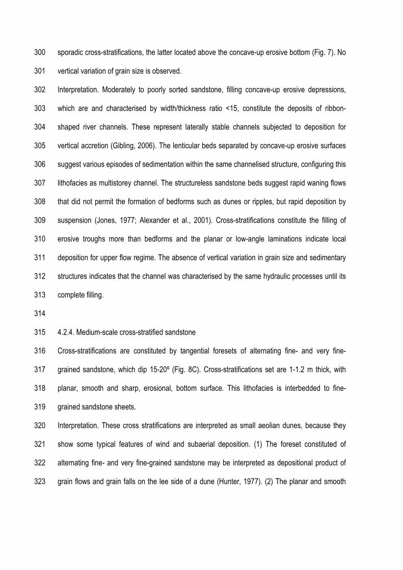
sporadic cross-stratifications, the latter located above the concave-up erosive bottom (Fig. 7). No 300
vertical variation of grain size is observed. 301
Interpretation. Moderately to poorly sorted sandstone, filling concave-up erosive depressions, 302
which are and characterised by width/thickness ratio <15, constitute the deposits of ribbon-303
shaped river channels. These represent laterally stable channels subjected to deposition for 304
vertical accretion (Gibling, 2006). The lenticular beds separated by concave-up erosive surfaces 305
suggest various episodes of sedimentation within the same channelised structure, configuring this 306
lithofacies as multistorey channel. The structureless sandstone beds suggest rapid waning flows 307
that did not permit the formation of bedforms such as dunes or ripples, but rapid deposition by 308
suspension (Jones, 1977; Alexander et al., 2001). Cross-stratifications constitute the filling of 309
erosive troughs more than bedforms and the planar or low-angle laminations indicate local 310
deposition for upper flow regime. The absence of vertical variation in grain size and sedimentary 311
structures indicates that the channel was characterised by the same hydraulic processes until its 312
complete filling. 313
314
4.2.4. Medium-scale cross-stratified sandstone 315
Cross-stratifications are constituted by tangential foresets of alternating fine- and very fine-316
grained sandstone, which dip 15-20º (Fig. 8C). Cross-stratifications set are 1-1.2 m thick, with 317
planar, smooth and sharp, erosional, bottom surface. This lithofacies is interbedded to fine-318
grained sandstone sheets. 319
Interpretation. These cross stratifications are interpreted as small aeolian dunes, because they 320
show some typical features of wind and subaerial deposition. (1) The foreset constituted of 321
alternating fine- and very fine-grained sandstone may be interpreted as depositional product of 322
grain flows and grain falls on the lee side of a dune (Hunter, 1977). (2) The planar and smooth 323
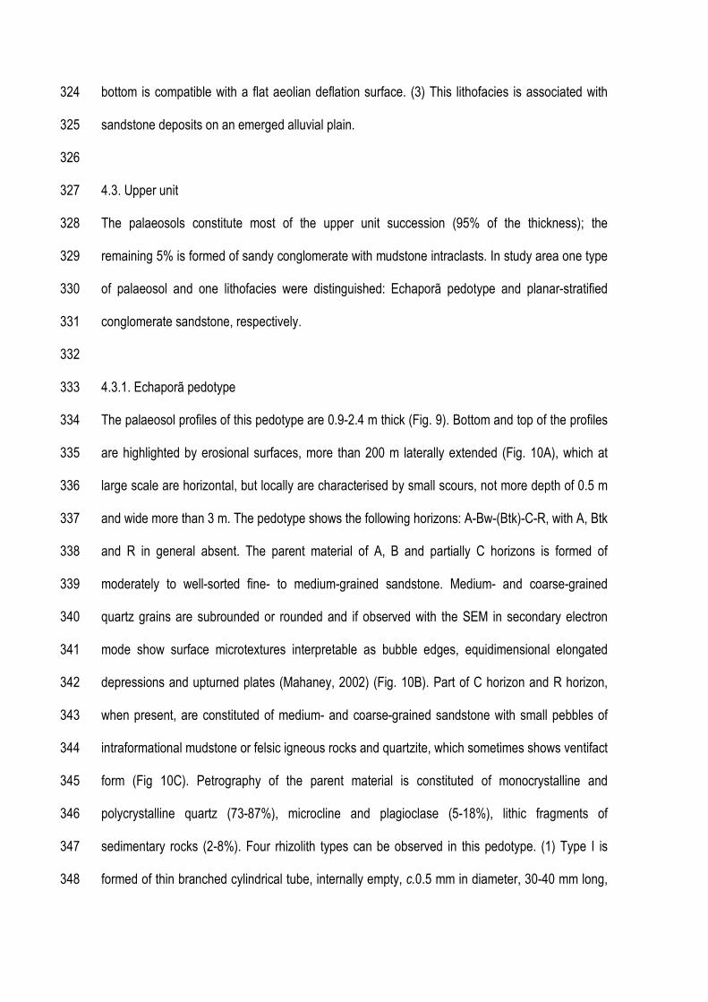
bottom is compatible with a flat aeolian deflation surface. (3) This lithofacies is associated with 324
sandstone deposits on an emerged alluvial plain. 325
326
4.3. Upper unit 327
The palaeosols constitute most of the upper unit succession (95% of the thickness); the 328
remaining 5% is formed of sandy conglomerate with mudstone intraclasts. In study area one type 329
of palaeosol and one lithofacies were distinguished: Echaporã pedotype and planar-stratified 330
conglomerate sandstone, respectively. 331
332
4.3.1. Echaporã pedotype 333
The palaeosol profiles of this pedotype are 0.9-2.4 m thick (Fig. 9). Bottom and top of the profiles 334
are highlighted by erosional surfaces, more than 200 m laterally extended (Fig. 10A), which at 335
large scale are horizontal, but locally are characterised by small scours, not more depth of 0.5 m 336
and wide more than 3 m. The pedotype shows the following horizons: A-Bw-(Btk)-C-R, with A, Btk 337
and R in general absent. The parent material of A, B and partially C horizons is formed of 338
moderately to well-sorted fine- to medium-grained sandstone. Medium- and coarse-grained 339
quartz grains are subrounded or rounded and if observed with the SEM in secondary electron 340
mode show surface microtextures interpretable as bubble edges, equidimensional elongated 341
depressions and upturned plates (Mahaney, 2002) (Fig. 10B). Part of C horizon and R horizon, 342
when present, are constituted of medium- and coarse-grained sandstone with small pebbles of 343
intraformational mudstone or felsic igneous rocks and quartzite, which sometimes shows ventifact 344
form (Fig 10C). Petrography of the parent material is constituted of monocrystalline and 345
polycrystalline quartz (73-87%), microcline and plagioclase (5-18%), lithic fragments of 346
sedimentary rocks (2-8%). Four rhizolith types can be observed in this pedotype. (1) Type I is 347
formed of thin branched cylindrical tube, internally empty, c.0.5 mm in diameter, 30-40 mm long, 348
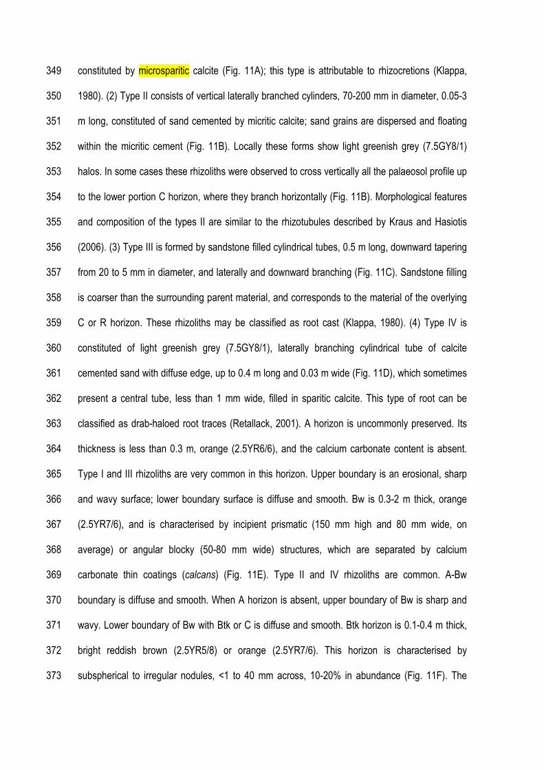
constituted by microsparitic calcite (Fig. 11A); this type is attributable to rhizocretions (Klappa, 349
1980). (2) Type II consists of vertical laterally branched cylinders, 70-200 mm in diameter, 0.05-3 350
m long, constituted of sand cemented by micritic calcite; sand grains are dispersed and floating 351
within the micritic cement (Fig. 11B). Locally these forms show light greenish grey (7.5GY8/1) 352
halos. In some cases these rhizoliths were observed to cross vertically all the palaeosol profile up 353
to the lower portion C horizon, where they branch horizontally (Fig. 11B). Morphological features 354
and composition of the types II are similar to the rhizotubules described by Kraus and Hasiotis 355
(2006). (3) Type III is formed by sandstone filled cylindrical tubes, 0.5 m long, downward tapering 356
from 20 to 5 mm in diameter, and laterally and downward branching (Fig. 11C). Sandstone filling 357
is coarser than the surrounding parent material, and corresponds to the material of the overlying 358
C or R horizon. These rhizoliths may be classified as root cast (Klappa, 1980). (4) Type IV is 359
constituted of light greenish grey (7.5GY8/1), laterally branching cylindrical tube of calcite 360
cemented sand with diffuse edge, up to 0.4 m long and 0.03 m wide (Fig. 11D), which sometimes 361
present a central tube, less than 1 mm wide, filled in sparitic calcite. This type of root can be 362
classified as drab-haloed root traces (Retallack, 2001). A horizon is uncommonly preserved. Its 363
thickness is less than 0.3 m, orange (2.5YR6/6), and the calcium carbonate content is absent. 364
Type I and III rhizoliths are very common in this horizon. Upper boundary is an erosional, sharp 365
and wavy surface; lower boundary surface is diffuse and smooth. Bw is 0.3-2 m thick, orange 366
(2.5YR7/6), and is characterised by incipient prismatic (150 mm high and 80 mm wide, on 367
average) or angular blocky (50-80 mm wide) structures, which are separated by calcium 368
carbonate thin coatings (calcans) (Fig. 11E). Type II and IV rhizoliths are common. A-Bw 369
boundary is diffuse and smooth. When A horizon is absent, upper boundary of Bw is sharp and 370
wavy. Lower boundary of Bw with Btk or C is diffuse and smooth. Btk horizon is 0.1-0.4 m thick, 371
bright reddish brown (2.5YR5/8) or orange (2.5YR7/6). This horizon is characterised by 372
subspherical to irregular nodules, <1 to 40 mm across, 10-20% in abundance (Fig. 11F). The 373
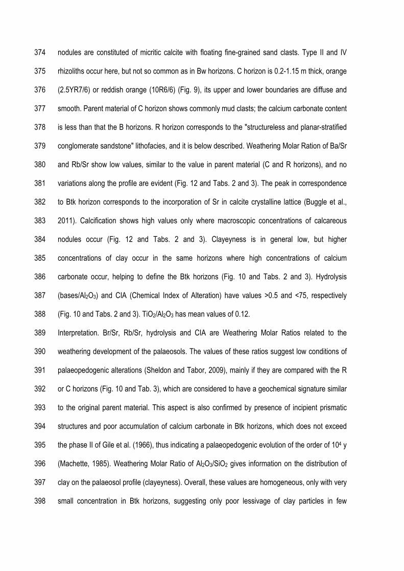
nodules are constituted of micritic calcite with floating fine-grained sand clasts. Type II and IV 374
rhizoliths occur here, but not so common as in Bw horizons. C horizon is 0.2-1.15 m thick, orange 375
(2.5YR7/6) or reddish orange (10R6/6) (Fig. 9), its upper and lower boundaries are diffuse and 376
smooth. Parent material of C horizon shows commonly mud clasts; the calcium carbonate content 377
is less than that the B horizons. R horizon corresponds to the "structureless and planar-stratified 378
conglomerate sandstone" lithofacies, and it is below described. Weathering Molar Ration of Ba/Sr 379
and Rb/Sr show low values, similar to the value in parent material (C and R horizons), and no 380
variations along the profile are evident (Fig. 12 and Tabs. 2 and 3). The peak in correspondence 381
to Btk horizon corresponds to the incorporation of Sr in calcite crystalline lattice (Buggle et al., 382
2011). Calcification shows high values only where macroscopic concentrations of calcareous 383
nodules occur (Fig. 12 and Tabs. 2 and 3). Clayeyness is in general low, but higher 384
concentrations of clay occur in the same horizons where high concentrations of calcium 385
carbonate occur, helping to define the Btk horizons (Fig. 10 and Tabs. 2 and 3). Hydrolysis 386
(bases/Al2O3) and CIA (Chemical Index of Alteration) have values >0.5 and <75, respectively 387
(Fig. 10 and Tabs. 2 and 3). TiO2/Al2O3 has mean values of 0.12. 388
Interpretation. Br/Sr, Rb/Sr, hydrolysis and CIA are Weathering Molar Ratios related to the 389
weathering development of the palaeosols. The values of these ratios suggest low conditions of 390
palaeopedogenic alterations (Sheldon and Tabor, 2009), mainly if they are compared with the R 391
or C horizons (Fig. 10 and Tab. 3), which are considered to have a geochemical signature similar 392
to the original parent material. This aspect is also confirmed by presence of incipient prismatic 393
structures and poor accumulation of calcium carbonate in Btk horizons, which does not exceed 394
the phase II of Gile et al. (1966), thus indicating a palaeopedogenic evolution of the order of 104 y 395
(Machette, 1985). Weathering Molar Ratio of Al2O3/SiO2 gives information on the distribution of 396
clay on the palaeosol profile (clayeyness). Overall, these values are homogeneous, only with very 397
small concentration in Btk horizons, suggesting only poor lessivage of clay particles in few 398

developed palaeosol profiles. To define the time of formation of the palaeosol profiles we can 399
apply an equation of Sheldon (2003) 400
Tf = 17.07 TBt2 + 645.8TBt 401
where Tf is time of formation, TBt is the original thickness of the Bt horizons. This equation, using 402
the data of Markevich et al. (1990), relates the original thickness of the Bt horizon with the 403
development time of the palaeosols. Actually, the development of Bt horizon is related to the time, 404
because the illuviation of clay from the upper horizons takes time (Retallack , 2001). The time 405
development obtained by three Btk horizons (Fig. 12) is 8,668, 14,415 and 62,860 y, indicating 406
relatively short periods of formation for these profiles. The other palaeosols profiles without Btk 407
horizon probably record lower times of development. Bw horizon may be interpreted as cambic 408
horizon, that is an horizon that presents some weathered characteristic, but not so developed to 409
be defined as other specific B horizon (Soil Survey Staff, 1999). For all these previous 410
characteristics the Echaporã Pedotype may be classified as Inceptisol (Soil Survey Staff, 1999, 411
2006) or calcic Protosol (Mack et al., 1993). 412
A clear idea on the depositional origin of the parent material does not exist because the 413
palaeopedogenesis disrupted all the original sedimentary structures, apart some features 414
preserved in C or R horizons. Some considerations can be based on the textural and grain-size 415
features of parent material. The moderate to well-sorted sandstone and the medium- to coarse-416
grained sandstone clasts with microtextural features, associated to wind-induced saltation 417
(Mahaney, 2002), testify a subaerial aeolian-dominated environment. Pebble-sized clasts suggest 418
that subaqueous flows could had have importance to generate this parent material, although 419
some of these clasts show ventifact features. Thus, it is not possible clearly define if the parent 420
material was originated by subaqueous flows that reworked wind transported material or vice 421
versa. Geochemical (TiO2/Al2O3) and petrographic data indicate felsic origin of the parent 422
material. 423
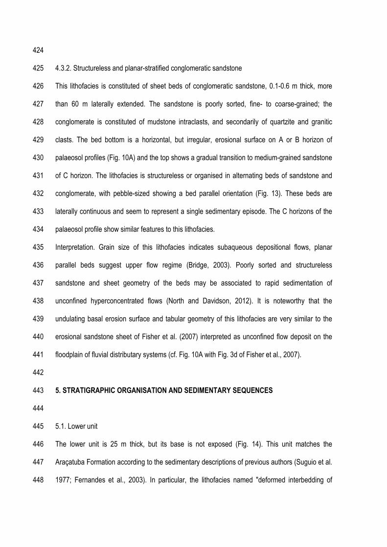
424
4.3.2. Structureless and planar-stratified conglomeratic sandstone 425
This lithofacies is constituted of sheet beds of conglomeratic sandstone, 0.1-0.6 m thick, more 426
than 60 m laterally extended. The sandstone is poorly sorted, fine- to coarse-grained; the 427
conglomerate is constituted of mudstone intraclasts, and secondarily of quartzite and granitic 428
clasts. The bed bottom is a horizontal, but irregular, erosional surface on A or B horizon of 429
palaeosol profiles (Fig. 10A) and the top shows a gradual transition to medium-grained sandstone 430
of C horizon. The lithofacies is structureless or organised in alternating beds of sandstone and 431
conglomerate, with pebble-sized showing a bed parallel orientation (Fig. 13). These beds are 432
laterally continuous and seem to represent a single sedimentary episode. The C horizons of the 433
palaeosol profile show similar features to this lithofacies. 434
Interpretation. Grain size of this lithofacies indicates subaqueous depositional flows, planar 435
parallel beds suggest upper flow regime (Bridge, 2003). Poorly sorted and structureless 436
sandstone and sheet geometry of the beds may be associated to rapid sedimentation of 437
unconfined hyperconcentrated flows (North and Davidson, 2012). It is noteworthy that the 438
undulating basal erosion surface and tabular geometry of this lithofacies are very similar to the 439
erosional sandstone sheet of Fisher et al. (2007) interpreted as unconfined flow deposit on the 440
floodplain of fluvial distributary systems (cf. Fig. 10A with Fig. 3d of Fisher et al., 2007). 441
442
5. STRATIGRAPHIC ORGANISATION AND SEDIMENTARY SEQUENCES 443
444
5.1. Lower unit 445
The lower unit is 25 m thick, but its base is not exposed (Fig. 14). This unit matches the 446
Araçatuba Formation according to the sedimentary descriptions of previous authors (Suguio et al. 447
1977; Fernandes et al., 2003). In particular, the lithofacies named "deformed interbedding of 448
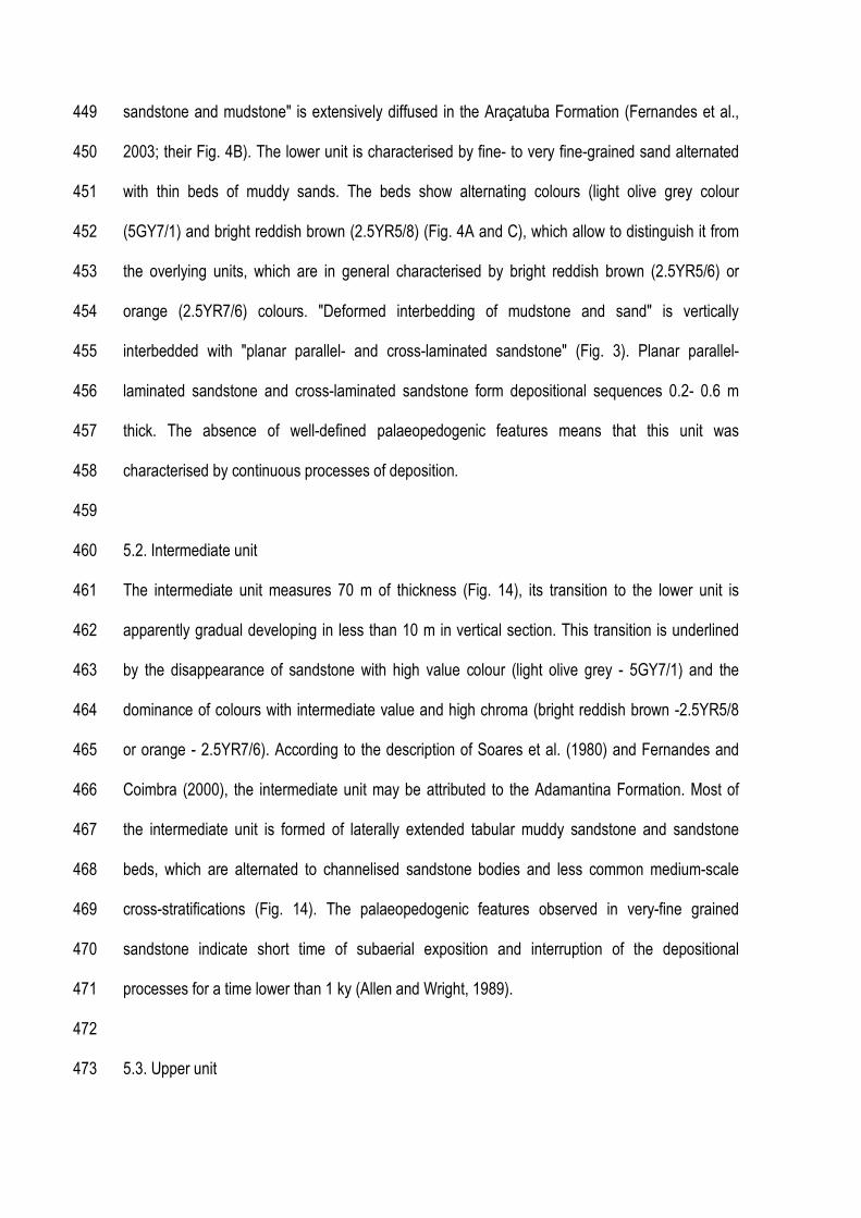
sandstone and mudstone" is extensively diffused in the Araçatuba Formation (Fernandes et al., 449
2003; their Fig. 4B). The lower unit is characterised by fine- to very fine-grained sand alternated 450
with thin beds of muddy sands. The beds show alternating colours (light olive grey colour 451
(5GY7/1) and bright reddish brown (2.5YR5/8) (Fig. 4A and C), which allow to distinguish it from 452
the overlying units, which are in general characterised by bright reddish brown (2.5YR5/6) or 453
orange (2.5YR7/6) colours. "Deformed interbedding of mudstone and sand" is vertically 454
interbedded with "planar parallel- and cross-laminated sandstone" (Fig. 3). Planar parallel-455
laminated sandstone and cross-laminated sandstone form depositional sequences 0.2- 0.6 m 456
thick. The absence of well-defined palaeopedogenic features means that this unit was 457
characterised by continuous processes of deposition. 458
459
5.2. Intermediate unit 460
The intermediate unit measures 70 m of thickness (Fig. 14), its transition to the lower unit is 461
apparently gradual developing in less than 10 m in vertical section. This transition is underlined 462
by the disappearance of sandstone with high value colour (light olive grey - 5GY7/1) and the 463
dominance of colours with intermediate value and high chroma (bright reddish brown -2.5YR5/8 464
or orange - 2.5YR7/6). According to the description of Soares et al. (1980) and Fernandes and 465
Coimbra (2000), the intermediate unit may be attributed to the Adamantina Formation. Most of 466
the intermediate unit is formed of laterally extended tabular muddy sandstone and sandstone 467
beds, which are alternated to channelised sandstone bodies and less common medium-scale 468
cross-stratifications (Fig. 14). The palaeopedogenic features observed in very-fine grained 469
sandstone indicate short time of subaerial exposition and interruption of the depositional 470
processes for a time lower than 1 ky (Allen and Wright, 1989). 471
472
5.3. Upper unit 473

The upper unit is c.150 m thick and (Fig. 14) can be attributed to the Marília Formation, because 474
it is located in the same area where Soares et al. (1980) defined the strato-type of Marília 475
Formation and coarser grain-size, general absence of sedimentary structures and presence of 476
carbonate nodules are features already described by Soares et al. (1980) as typical for this unit. 477
The transition from intermediate unit develops in c.20 m and it is characterised by the progressive 478
appearance of palaeosol profiles. The upper unit is organised in cyclic alternations of deposits 479
(structureless and planar-stratified conglomeratic sandstone) and palaeosols (Echaporã 480
pedotype) (Fig. 15). These sequences, 0.9 to 2.4 m thick, are separated by erosional surfaces, 481
more than 200 m in extension with scours up to 0.5 m depth and 3 m wide (Fig. 10A). The 482
deposits are located at the base of the sequence (Fig. 15), but sometimes, above the erosional 483
surface only the C horizon with poorly-preserved sedimentary structures is observed. Palaeosol 484
profiles separated by deposits and/or C horizons are denominated compound profiles (Morrison, 485
1978). The formation of compound profiles entails that the depositional and pedogenic processes 486
were separated in time and that sedimentation was sufficiently rapid and thick for not allow to the 487
pedogenesis to incorporate the material within the soil profile. Daniels (2003) highlighted in 488
present floodplain of semiarid environment that the sedimentation rate above 5 mm/y inhibits the 489
pedogenic processes and allows to the preservation of the sedimentary structures. Echaporã 490
pedotype is an Inceptisol, i.e. a poorly developed palaeosol. Time and not favourable climate 491
conditions influence the formation of Inceptisols (Foss et al., 1993). Time may be defined 492
applying the time-function of Sheldon (2003) to the palaeosol profiles with Btk horizons, where we 493
verified times of formation from 8,668 to 62,860 y. In this study case, climate may be considered 494
a secondary factor, because this same unit in the northern portion of the Bauru Basin shows in 495
similar climate conditions well-developed palaeosols (Basilici et al., 2009). Thus, the time may be 496
considered to be the main factor responsible for the immaturity of these palaeosols. 497
498

6. DEPOSITIONAL RECONSTRUCTION OF THE PALAEOENVIRONMENT AND MODEL OF 499
EVOLUTION OF THE BAURU GROUP 500
This paragraph reconstructs the depositional conditions and the possible evolution of the three 501
units of the Bauru Group exposed in Serra de Echaporã. 502
503
6.1. Lower unit: basinal salt flat system 504
Deformed sandstone and mudstone constitutes three-quarters of the thickness of the deposits of 505
the lower unit (Fig. 3), therefore this lithofacies represents the dominant depositional system. This 506
was produced by the deposition of sand and mud by subaqueous or subaerial flows on a thin 507
saline efflorescent crust, which covered the surface of a salt flat (Smoot and Lowenstein, 1991; 508
Smoot and Castens-Seidell, 1994; Goodall et al., 2000). The clastic material was deposited 509
above an irregular saline crust and successively it was deformed by the contemporaneous growth 510
or dissolution of salts. Evaporite minerals did not preserved due to the undersaturated 511
groundwater and the relatively frequent floods. The salt flat area was rather extended because, 512
although the maximum observed exposure of these deposits is few hundreds of metres, 513
Fernandes et al. (2003) recognised similar lithofacies c.100 km northward from the study area. 514
Occasional floods on the salt flat are indicated by planar parallel- and cross-laminated sandstone 515
sequences. This lithofacies testifies rapid subaqueous flows, which spread sand on surfaces 516
some tens of metres wide. The sand initially was deposited in plane bed form, followed with the 517
decreasing of the flow velocity by climbing current ripples; at calm water, a thin bed of muddy 518
sandstone covered the sand. These deposits probably reflect the construction of sheet deltas at 519
the margin of the flooded salt flat (Fig. 16A). Sheet deltas are shoreline subenvironments of dry or 520
saline mudflat settings, which are constituted of sand beds organised in vertical sequences of 521
planar parallel-laminations, climbing-ripple cross-laminations and thin beds of mud, which form 522
wedge-shaped flat bodies (Smoot and Lowenstein, 1991). On the standing waters, established 523
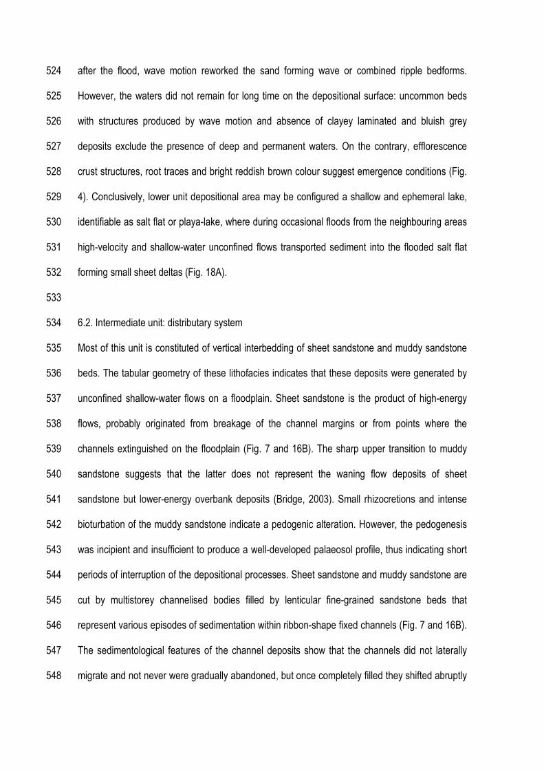
after the flood, wave motion reworked the sand forming wave or combined ripple bedforms. 524
However, the waters did not remain for long time on the depositional surface: uncommon beds 525
with structures produced by wave motion and absence of clayey laminated and bluish grey 526
deposits exclude the presence of deep and permanent waters. On the contrary, efflorescence 527
crust structures, root traces and bright reddish brown colour suggest emergence conditions (Fig. 528
4). Conclusively, lower unit depositional area may be configured a shallow and ephemeral lake, 529
identifiable as salt flat or playa-lake, where during occasional floods from the neighbouring areas 530
high-velocity and shallow-water unconfined flows transported sediment into the flooded salt flat 531
forming small sheet deltas (Fig. 18A). 532
533
6.2. Intermediate unit: distributary system 534
Most of this unit is constituted of vertical interbedding of sheet sandstone and muddy sandstone 535
beds. The tabular geometry of these lithofacies indicates that these deposits were generated by 536
unconfined shallow-water flows on a floodplain. Sheet sandstone is the product of high-energy 537
flows, probably originated from breakage of the channel margins or from points where the 538
channels extinguished on the floodplain (Fig. 7 and 16B). The sharp upper transition to muddy 539
sandstone suggests that the latter does not represent the waning flow deposits of sheet 540
sandstone but lower-energy overbank deposits (Bridge, 2003). Small rhizocretions and intense 541
bioturbation of the muddy sandstone indicate a pedogenic alteration. However, the pedogenesis 542
was incipient and insufficient to produce a well-developed palaeosol profile, thus indicating short 543
periods of interruption of the depositional processes. Sheet sandstone and muddy sandstone are 544
cut by multistorey channelised bodies filled by lenticular fine-grained sandstone beds that 545
represent various episodes of sedimentation within ribbon-shape fixed channels (Fig. 7 and 16B). 546
The sedimentological features of the channel deposits show that the channels did not laterally 547
migrate and not never were gradually abandoned, but once completely filled they shifted abruptly 548
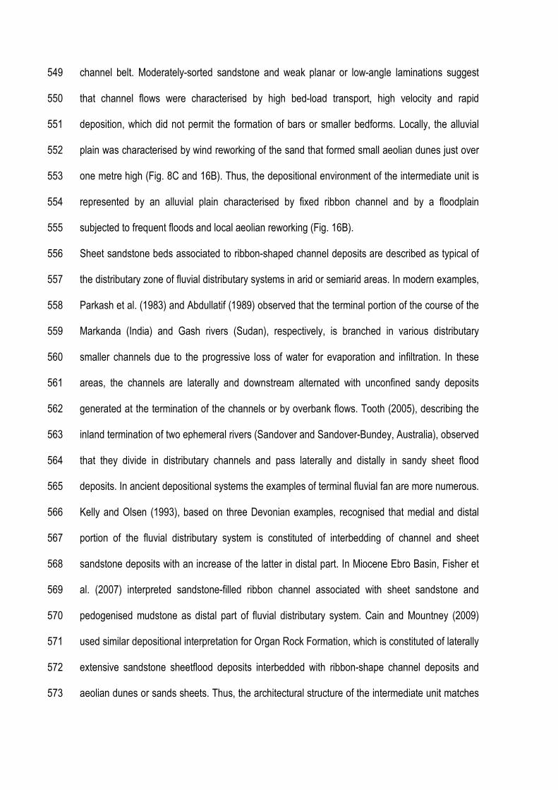
channel belt. Moderately-sorted sandstone and weak planar or low-angle laminations suggest 549
that channel flows were characterised by high bed-load transport, high velocity and rapid 550
deposition, which did not permit the formation of bars or smaller bedforms. Locally, the alluvial 551
plain was characterised by wind reworking of the sand that formed small aeolian dunes just over 552
one metre high (Fig. 8C and 16B). Thus, the depositional environment of the intermediate unit is 553
represented by an alluvial plain characterised by fixed ribbon channel and by a floodplain 554
subjected to frequent floods and local aeolian reworking (Fig. 16B). 555
Sheet sandstone beds associated to ribbon-shaped channel deposits are described as typical of 556
the distributary zone of fluvial distributary systems in arid or semiarid areas. In modern examples, 557
Parkash et al. (1983) and Abdullatif (1989) observed that the terminal portion of the course of the 558
Markanda (India) and Gash rivers (Sudan), respectively, is branched in various distributary 559
smaller channels due to the progressive loss of water for evaporation and infiltration. In these 560
areas, the channels are laterally and downstream alternated with unconfined sandy deposits 561
generated at the termination of the channels or by overbank flows. Tooth (2005), describing the 562
inland termination of two ephemeral rivers (Sandover and Sandover-Bundey, Australia), observed 563
that they divide in distributary channels and pass laterally and distally in sandy sheet flood 564
deposits. In ancient depositional systems the examples of terminal fluvial fan are more numerous. 565
Kelly and Olsen (1993), based on three Devonian examples, recognised that medial and distal 566
portion of the fluvial distributary system is constituted of interbedding of channel and sheet 567
sandstone deposits with an increase of the latter in distal part. In Miocene Ebro Basin, Fisher et 568
al. (2007) interpreted sandstone-filled ribbon channel associated with sheet sandstone and 569
pedogenised mudstone as distal part of fluvial distributary system. Cain and Mountney (2009) 570
used similar depositional interpretation for Organ Rock Formation, which is constituted of laterally 571
extensive sandstone sheetflood deposits interbedded with ribbon-shape channel deposits and 572
aeolian dunes or sands sheets. Thus, the architectural structure of the intermediate unit matches 573

well with the medial or distal part of the distributary zone of a fluvial distributary system (Kelly e 574
Olsen, 1993) (Fig. 18B). 575
576
6.3. Upper unit: distal distributary system in more arid climate 577
The upper unit is considerably different from the other two units because is palaeosol dominated 578
and slightly coarser in grain size. Compound profiles of palaeosols indicate interruptions of the 579
depositional processes of the order of 104 y, which caused the almost complete alteration of the 580
sediments. Structureless and planar-stratified conglomeratic sandstone and some relicts of 581
sedimentary features preserved in C horizons permit to associate the origin of the parent material 582
to the deposition by unconfined subaqueous flows (Fig. 17A). Wind action is testified by surface 583
textural features observed in sand grains and ventifacts, but no data exist to unravel if the wind 584
formed deposits or the subaqueous flows reworked previous aeolian transported material. Thus, 585
the environmental conditions of the upper unit may be visualised as a flat area subjected to short 586
duration and periodical unconfined floods, which probably reworked previous aeolian transported 587
sands, (Fig. 17A) and successive prolonged periods of pedogenesis (Fig. 17B). 588
The three units are characterised by gradual stratigraphic transition. Therefore, it is likely that 589
these units constitute portions of the same depositional system. If the lower and intermediate 590
units can be interpreted as basinal and medial or distal zone of a fluvial distributary system, 591
respectively (Kelly and Olsen, 1993; Nichols, 2005; Nichols and Fisher, 2007; Cain and 592
Mountney, 2009) (Fig. 18 A and B), inserting the upper unit in this depositional system results a 593
little complex. This difficulty is mainly related to the fact that the upper unit is constituted almost 594
exclusively by palaeosols, and they are not considered into the model of fluvial distributary 595
system, if not marginally. For example, Fisher et al. (2007) described floodplain mudstone with 596
pedogenic modifications and Cain and Mountney (2009) recognised palaeosol profiles with Bk 597

horizons (calcrete) as part of the overbank deposits. Nevertheless, in both cases the palaeosol 598
types were not identified and the relationship with the depositional processes was not analysed. 599
In upper unit, the abundance of palaeosols suggests decrease in sedimentation rate. Vertical 600
alternations of compound palaeosols, interpreted as moderately developed palaeosols 601
(Inceptisols), indicate sedimentation processes with recurrence time of the order of 104y (Fig. 15). 602
The climate is one of the main factors that governs the depositional processes in endorheic 603
basins (Nichols, 2005). In fact, the hinterland climate of distributary fluvial systems controls the 604
supply of water and the basin climate the loss of water for evaporation (Nichols, 2005; Nichols 605
and Fisher, 2007). Therefore, the lesser availability of material observed in upper unit may be 606
associated to more arid climate that reduced the discharge of the rivers and consequently the 607
input of sediment into the basin. Chumakov et al. (1995) published climate global maps for the 608
Upper Cretaceous, and collocated the study area in Southern Hot Arid belt. Several features 609
testify a semiarid climate for the upper unit formation. (i) Calcium carbonate concentration in 610
palaeosol horizons (Btk horizons) indicates some degree of aridity (Sheldon and Tabor, 2009). (ii) 611
Long tap root traces (type II) are related to deep groundwater level in the soil. (iii) Grain size and 612
general textural features of the parent material of the upper unit testify aeolian transport. (iv) 613
Unconfined flow deposits are common in semiarid environment due to improvise and catastrophic 614
floods (Fielding et al., 2009). More arid conditions provoked the decrease of the sedimentary 615
input of the fluvial distributary system. The sheet-shaped compound palaeosol profiles, whose 616
parent material was interpreted as deposited from unconfined flows, and the absence of channel 617
deposits allow to attribute this unit to the more distal portion of a fluvial distributary system, which 618
was invaded by low-frequency and occasional unconfined flood. Thus, the transition from 619
intermediate to upper unit indicates a general retrogradation of the system (Fig. 18C). 620
621
7. CONCLUSIONS 622

The application of genetic criteria, which consider sedimentary facies of the deposits and 623
palaeosols, to the stratigraphy of the south-eastern portion of the Bauru Group can help to 624
unravel the complicated and apparently featureless stratigraphy of this unit and its sedimentary 625
evolution. In this area, three lithostratigraphic units, informally named as lower, intermediate and 626
upper units, were recognised. They may be identified as Araçatuba, Adamantina and Marília 627
formations, respectively. 628
The three units constitute a continuous sedimentary succession that may be interpreted as 629
depositional product of a fluvial distributary system. The lower and intermediate units are 630
interpreted as basinal and distal or medial portion of an endorheic fluvial distributary system. The 631
upper unit, which is mostly constituted for palaeosols, does not fit well to the proposed models of 632
fluvial distributary system. In fact, although the palaeosols are known in these depositional 633
systems, they are not considered as important element of this depositional model. Palaeosols of 634
the upper unit represent poor and occasional input of sediment into the depositional system, 635
probably due to a general drying up of the climate, which reduced the river discharge and 636
consequently the generation of sediment into the basin. Preserved sedimentary feature and 637
erosive bottom and sheet shaped of the palaeosol profiles suggest that occasional unconfined 638
flow deposited the parent material of the upper unit. These features and the absence of 639
channelised bodies allow interpreting this unit as more distal portion of a fluvial distributary 640
system where occasional unconfined flow deposited sheet sandstone. During the pauses of 641
sedimentation moderately developed palaeosols (Inceptisols) formed above the deposits for a 642
time of the order of 104y. 643
In conclusion, the coordinate study of palaeosol and sediments permitted to unravel the 644
stratigraphy of the apparently featureless Bauru Group, its sedimentary palaeoenvironment as 645
fluvial distributary system and to insert the palaeosol dominated upper unit into this depositional 646
model. 647

648
ACKNOWLEDGES 649
The authors would like to thank FAPESP (Project 2012/23209-0) and CNPq (Universal 650
4742272013-8) for having financed this study. 651
652
REFERENCES 653
Abdullatif, O.M. (1989) Channel-fill and sheet-flood facies sequences in the ephemeral terminal 654
River Gash, Kassala, Sudan. Sed. Geol., 63, 171–184. 655
Alexander, J., Bridge, J.S., Cheel, R.J., Leclair, S.F., 2001. Bedforms and associated 656
sedimentary structures formed under supercritical water flows over aggrading sand beds. 657
Sedimentology 48, 133–152. 658
Allen, J.R.N., Wright, V.P. (1989) Palaeosols in siliciclastic sequences. Postgraduate Research 659
Institute for Sedimentology, University of Reading, Reading, pp. 97. 660
Barcelos J.H. 1984. Reconstrução paleogeográfica da sedimentação do Grupo Bauru baseada 661
na sua redefinição estratigráfíca parcial.em território paulista e no estudo preliminar fora do 662
Estado de São Paulo. Inst. de Geociências e Ciências Exatas, Universidade Estadual Paulista, 663
Rio Claro, Tese de Livre-Docência, 190 p. 664
Basilici, G., Dal’ Bó, P.F.F., Ladeira, F.S.B. 2009. Climate-induced sediment-palaeosol cycles in a 665
Late Cretaceous dry aeolian sand sheet: Marília Formation (North-West Bauru Basin, Brazil). 666
Sedimentology, 56: 1876-1904 667
Basilici, G., Dal' Bó, P.F.F. 2010. Anatomy and controlling factors of a Late Cretaceous aeolian 668
san sheet: the Marília and the Adamantina formations, NW Bauru Basin, Brazil. Sedimentary 669
Geology, 226: 71–93. 670
Basilici, G. and Dal' Bó, F.P. (2014) Influence of subaqueous processes on the construction and 671
accumulation of an aeolian sand sheet. Earth Surface Processes and Landforms, 39, 1014–1029. 672
Batezelli, 2015. Continental systems tracts of the Brazilian Cretaceous Bauru Basin and their 673
relationship to the tectonic and climatic evolution of South America. Basin Research, Accepted 674
article. 675
Best, J. and Bridge, J., 1992. The morphology and dynamics of low amplitude bedwaves upon 676
upper stage plane beds and the preservation of planar laminae. Sedimentology 39,737-752 677
Bridge, J. and Best, J., 1997. Preservation of planar laminae due to migration of low-relief bed 678
waves over aggrading upper-stage plane beds: comparison of experimental data with theory 679
Sedimentology, 44, 253-262 680
Bridge, J.S. (2003) Rivers and Floodplains. Blackwell, Oxford, UK. pp. 491 681
Buggle, B., Glaser, B., Hambach, U., Gerasimenko, N. and Marković, S. (2011) An evaluation of 682
geochemical weathering indices in loess-palaeosol studies. Quaternary International, 240, 12-21. 683
Cain STEPHEN A. and Mountney NIGEL P. (2009) Spatial and temporal evolution of a terminal 684
fluvial fan system:the Permian Organ Rock Formation, South-east Utah, USA Sedimentology 56, 685
1774–1800 686
Chumakov, N.M., Zharkov, M.A., Herman, A.B., Doludenko, M.P., Kalandadze, N.N., Lebedev, 687
E.L., Ponomarenko, A.G. and Rautian, A.S. (1995) Climatic belts of the mid-Cretaceous time. 688
Stratigr. Geol. Correlation, 3, 241–260. 689
Dal’ Bó, P.F.F., Basilici, G., Angelica, R.S., Ladeira, F.S.B. 2009. Paleoclimatic interpretations 690
from pedogenic calcretes in a Maastrichtian semiarid eolian sand-sheet palaeoenvironment: 691
Marília Formation (Bauru Basin, southeastern Brazil). Cretaceous Research, 30: 659-675. 692
Dal' Bó, P.F.F., Basilici, G., Angélica, R.S. 2010. Factors of palaeosol formation in a Late 693
Cretaceous eolian sand sheet paleoenvironment, Marília Formation, Southeastern Brazil 694
Palaeogeography, Palaeoclimatology, Palaeoecology, 292: 349–365. 695
Daniels J. M. (2003) Floodplain aggradation and pedogenesis in a semiarid environment. 696
Geomorphology 56 (2003) 225–242 697
De Raaf, J. F. M., Boersma J. R. and Van Gelder A. (1977) Wave-generated structures and 698
sequences from a shallow marine succession, Lower Carboniferous, County Cork, Ireland. 699
Sedimentology, 24, 451-483 700
Fernandes, L.A., Coimbra, A.M. 2000. Revisão estratigráfica da parte oriental da Bacia Bauru 701
(Neocretáceo). Revista Brasileira de Geociências, 30: 717-728. 702
Fernandes L. A., Giorgio Basilici (2009) - Transition of ephemeral palustrine to aeolian deposits in 703
a continental arid – semiarid environment (Upper Cretaceous Bauru Basin, Brazil). Cretaceous 704
Research 30, 605–614 705
Fernandes, L.A., Giannini. P.C.F. and Góes, A.M. (2003). Araçatuba Formation: palustrine 706
deposits from the initial sedimentation phase of the Bauru Basin. Anais da Academia Brasileira 707
de Ciências 75(2), 173-187 708
Fernandes, L.A. and Magalhães Ribeiro, C.M. (2015) Evolution and palaeoenvironment of the 709
Bauru Basin (Upper Cretaceous, Brazil) Journal of South American Earth Sciences 61, 71-90 710
Fielding, C.R., Allen, J.P., Alexander, J., Gibling. M.R., (2009). Facies model for fluvial systems in 711
the seasonal tropics and subtropics. Geology, 37, 7, 623–626 712
Fielding, C. R. (2006) Upper flow regime sheets, lenses and scour fills: Extending the range of 713
architectural elements for fluvial sediment bodies Sedimentary Geology 190, pp. 227–240; 714
Fisher J.A., Nichols G.J., Waltham, D.A., 2007. Unconfined flow deposits in distal sectors of 715
fluvial distributary systems: Examples from the Miocene Luna and Huesca Systems, northern 716
Spain. Sedimentary Geology, 195, 55–73 717
Foss, J.E, Moormann, F.R. and Rieger, S. (1983) Inceptisols. In: Pedogenesis and Soil 718
Taxonomy. II. The Soil Orders (Eds Wilding, L.P., Smeck N.E. and Hall, G.F.), Development in 719
Soil Science, Elsevier, 11B, 355–381. 720
Friend, P.F. (1978) Distinctive features of some ancient river systems. In: Fluvial Sedimentology 721
(Ed. A.D. Miall), Mem. Can. Soc. Petrol. Geol., 5, 531–542. 722

Gibling, M.R. (2006). Width and thickness of fluvial channel bodies and valley fills in the 723
geological record: a literature compilation and classification. Journal of Sedimentary Research, 724
2006, v. 76, 731–770 725
Gile, L.H., Peterson, F.F. and Grossman, R.B. (1966) Morphological and genetic sequences of 726
carbonate accumulation in desert soils. Soil Science, 101, 347–360. 727
Goodall, T. M., North C. P. and Glennie K. W. (2000) Surface and subsurface sedimentary 728
structures produced by salt crusts. Sedimentology, 47, 99-118 729
Hodgson, J.M. (1978). Soil Sampling and Soil Description. Clarendon Press, Oxford, 241 pp. 730
Hunter RE. 1977. Basic types of stratification in small aeolian dunes. Sedimentology 24: 361–731
387. 732
Jopling, A.V. and Walker, R.G. (1968). Morphology and origin of ripples-drift cross-lamination, 733
with examples from the Pleistocene of Massachusetts. Journal Sed. Petr., 38, 971-984 734
Kelly, S.B. and Olsen, H. (1993) Terminal fans – a review with reference to Devonian examples. 735
Sed. Geol., 85, 339–374. 736
Klappa, C. F. (1980) Rhizoliths in terrestrial carbonates : classification, recognition, genesis and 737
significance Sedimentology (1980) 27, 613-629 738
Jones, C. .M. (1977). The effects of varying discharge regimes on bedform sedimentary 739
structures in modern rivers. Geology, 5, 567-570. 740
Kraus Mary J. and Hasiotis Stephen T. (2006) Significance of different modes of rhizolith 741
preservation to interpreting paleoenvironmental and paleohydrologic settings: examples from 742
Paleogene paleosols, bighorn basin, Wyoming, U.S.A. Journal of Sedimentary Research, v. 76, 743
633–646 744
Machette, N.M. (1985) Calcic soils of the southwestern United States. In: Soils and Quaternary 745
Geology of the Southwestern United States (Ed D.L. Weide), Geological Society of America 746
Special Paper, 203, 10–21. 747
Mack, G.H., James, W.C. and Monger, H.C. (1993) Classification of paleosols. Geological 748
Society of American Bulletin, 105, 129–136. 749
Mahaney, W.C. (2002) Atlas of Sand Grain Surface Textures and Applications. Oxford University 750
Press, Oxford, 237 pp. 751
Markewich, H.W., Pavich, M.J., Buell, G.R., 1990. Contrasting soils and landscapes of the 752
Piedmont and Coastal Plain, eastern United States. Geomorphology 3, 417–447. 753
McKee, E.D., Crosbye, J. & Berryhillh, .C. (1967) Flood deposits. Bijou Creek, Colorado, June 754
1965. J. Sedim. Petrol. 37, 829-85 1. 755
Mezzalira, S., e Arruda, M.R., 1965. Observações geológicas na região do Pontal do 756
Paranapanema, Estado de São Paulo. Anais Academia Brasileira de Ciências, 37: 69·77. 757
Morrison, R.B. (1978) Quaternary soil stratigraphy—concepts, methods, and problems. In: 758
Quaternary Soils (Ed Mahaney, W.C.), Geo Abstracts, Norwich, 77–108. 759
Mukerji, A.B. (1976) Terminal fans of inland streams in Sutlej–Yamuna Plain, India. Zeits. 760
Geomorphol. Neue Folge, Bd. 20, 190–204. 761
Nichols, G. J. 2005. Sedimentary evolution of the Lower Clair Group, Devonian, West of 762
Shetland: climate and sediment supply controls on fluvial, aeolian and lacustrine deposition. In: 763
Doré, A. G. & Vining, B. A. (eds) Petroleum Geology: North-West Europe and Global 764
Perspectives—Proceedings of the 6th Petroleum Geology Conference, 957–967. 765
Nichols, G.J. and Fisher, J.A. (2007) Processes, facies and architecture of fluvial distributary 766
system deposits. Sed. Geol., 195, 75–90. 767
North, C.P. and Warwick, G.L. (2007) Fluvial fans: myths, misconceptions, and the end of the 768
terminal-fan model. J. Sed. Res., 77, 693–701. 769
North C.P., Davidson S.K. (2012). Unconfined alluvial flow processes: Recognition and 770
interpretation of their deposits, and the significance for palaeogeographic reconstruction Earth-771
Science Reviews 111, 199–223. 772
Paula e Silva de, F., Chang, H.K., Caetano-Chang, M.R. 2009. Sedimentation of the Cretaceous 773
Bauru Group in São Paulo, Paraná Basin, Brazil. Journal of South American Earth Sciences, 28: 774
25–39. 775
Parkash, B., Awasthi, A.K. and Gohain, K. (1983) Lithofacies of the Markanda terminal fan, 776
Kurukshetra district, Haryana, India. In: Modern and Ancient Fluvial Systems (Eds J.D. Collinson 777
and J. Lewin), Spec. Publ. Int. Assoc. Sedimentol., 6, 337–344. 778
Retallack, G.J. (2001) Soils of the Past: an Introduction to Paleopedology. 2nd ed. Blackwell, 779
Oxford, 404 pp. 780
Retallack, G.J. (2005) Pedogenic carbonate proxies for amount and seasonality of precipitation in 781
paleosols. Geology, 33, 333–336. 782
Saéz, A., Anadón, P., Herrero, M.J. and Moscariello, A. (2007) Variable style of transition 783
between Palaeogene fluvial fan and lacustrine systems, southern Pyrenean foreland, NE Spain. 784
Sedimentology, 54, 367–390. 785
Sheldon, N.D., 2003. Pedogenesis and geochemical alteration of the picture gorge subgroup, 786
Columbia River Basalt, Oregon. Geological Society of America Bulletin 115, 1377–1387. 787
Sheldon, N.D., Retallack, G.J., 2001. Equation for compaction of palaeosols due to burial. 788
Geology 29, 247–250. 789
Sheldon, N.D. and Tabor, N.J. (2009) Quantitative paleoenvironmental and paleoclimatic 790
reconstruction using paleosols. Earth Science Reviews, 95, 1–52. 791
Sheldon, N.D., Retallack, G.J., Tanaka, S., 2002. Geochemical climofunctions from North 792
America soils and application to paleosols across the Eocene–Oligocene boundary in Oregon. 793
Journal of Geology 110, 687–696. 794
Smoot, J. P. and Olsen, P. E. (1988) Massive mudstones in basin analysis and paleoclimatic 795
interpretation of the Newark Supergroup (In Manspeizer W. ed.) Triassic Jurassic Rifting North 796
America and North Africa. Amsterdam, Elsevier p. 249 274 797
Smoot, J. P. and Lowenstein, T. K., 1991. Depositional environments of non marine evaporites. In 798
Melvin, J. L. ed. Evaporites Petroleum and Mineral Resources. Amsterdam Elsevier p. 189-347 799
Smoot, J. P., 1991. Sedimentary facies and depositional environments of early Mesozoic Newark 800
Supergroup basins, eastern North America. Palaeogeography, Palaeoclimatology, 801
Palaeoecology, 84, 369-423 802
Smoot, J.P. and Castens-Seidell, B. (1994) Sedimentary features produced by efflorescent 803
crusts, Saline Valley and Death Valley, California. In: Sedimentology and Geochemistry of 804
Modern Ancient Saline Lakes (Eds R.W. Renaut and W.M. Last), Spec. Publ. Soc. Econ. Paleont. 805
Miner., Tulsa, 50, 73±90. 806
Soares, P.C., Landim, P.M.B., Fulfaro, V.J., Neto, A.F.S. 1980. Ensaio de caracterizacão 807
estratigráfica do Cretáceo no Estado de São Paulo: Grupo Bauru. Revista Brasileira de 808
Geociências, 10: 177–185. 809
Soil Survey Staff (1999) Soil Taxonomy. A Basic System of Soil Classification for Making and 810
Interpreting Soil Surveys. US Department of Agriculture, Natural Resource Conservation Service, 811
Washington, D.C., Vol. 436, 871 pp. 812
Soil Survey Staff (2006) Keys to Soil Taxonomy, 10th edn. US Department of Agriculture, Natural 813
Resource Conservation Service, Washington, D.C., 332 pp. 814
Spice, B. and Skelton, P.W. (2003) In: Skelton P.W. The Cretaceous world. The Open University, 815
Cambridge University Press, Cambridge, 249-271 816
Suguio K., Fúlfaro V.J., Amaral G., Guidorzi L.A. 1977. Comportamentos estratigráficos e 817
estrutural da Formação Bauru nas regiões administrativas 7 (Bauru), 8 (São José do Rio Preto) e 818
9 (Araçatuba) no Estado de São Paulo. In: SBG/Núcleo SP, Simpósio de Geologia Regional, l, 819
São Paulo, Atas, p. 231 -247. 820
Suguio K. 1981. Fatores paleoambientes e paleoclimáticos e subdivisão estratigráfica do Grupo 821
Bauru. In:, SBG/Núcleo SP, Mesa Redonda: A Formação Bauru no Estado de São Paulo e 822
Regiões Adjacentes, São Paulo, Coletânea de trabalhos e debates, p. 15-26. 823
Tooth, S. 2005 Splay formation along the lower reaches of ephemeral rivers on the northern 824
plains of arid central Australia Journal of Sedimentary Research, v. 75, 636–649 825
Tunbridge, I.,P . (1981) Sandy high energy flood sedimentation--some criteria for recognition, with 826
an example from the Devonian of SW England. Sediment. Geol. 28, 79 95. 827
Tunbridge, I.P., 1984. Facies model for a sandy ephemeral stream and clay playa complex; the 828
Middle Devonian Trentishoe Formation of North Devon, U.K. Sedimentology, 31: 697-715. 829
830
CAPTIONS 831
Figure 1. Location map of the study areas. Previous study areas were considered in Basilici et al. 832
(2009), Dal' Bó et al. (2009) and Basilici and Dal' Bó (2010). 833
Figure 2. (A) Schematic geological map of the Bauru Basin. (B) Stratigraphic interpretation 834
according to Batezelli (2015). (C) Stratigraphic interpretation according to Fernandes and Ribeiro 835
(2015). 836
Figure 3. Detailed stratigraphic sketch of the lower unit (attributed to Araçatuba Formation). 837
Deformed interbedding of sandstone and mudstone (lithofacies dsm in the picture) constitute 838
most of the succession. Lithofacies: dsm = deformed interbedding of sandstone and mudstone; 839
pcs = planar parallel and cross-laminated sandstone. 840
Figure 4. Lower unit. The lithofacies deformed interbedding of sandstone and mudstone is 841
interpreted as deformed sediments by superficial growing of thin salt efflorescence crusts. (A) 842
Thin beds or laminae of sandstone (olive grey - 5GY7/1) and mudstone (bright reddish brown - 843
2.5YR5/8) show jagged lateral edge and cuspate margins. Some sandstone are characterised of 844
thin internal laminations (i). Protrusions of mudstone in sandstone patches (ii) can represent the 845

"popcorn" surface of salt crust. Mudstone and sandstone concave-up laminae (iii) are interpreted 846
as surface deformation features that correspond to polygonal forms on the salt flat surface. Coin: 847
20 mm. (B) Irregular patches of mudstone and sandstone (i) representing aggradational features 848
of salt efflorescence crusts. Bowl-shaped laminae of mudstone and sandstone (ii) reflect surface 849
deformation structures like polygons or mound shapes. Object for scale is 26 mm in diameter. (C) 850
(i) Small sandstone-filled depression can represent solution collapse structures associated with 851
efflorescent crust fabric. (ii) Bioturbation is present, but not common, this consists in small 852
sandstone-filled vertical tube, with circular section of 1-5 mm in diameter and 0.03-0.2 m high. 853
Object for scale is 26 mm in diameter. (D) Root trace with drab halo (arrowed) testifies iron 854
reduction and depletion under reducing conditions around the root walls. Coin: 20 mm. 855
Figure 5. Lower unit. Lithofacies planar parallel- and cross-laminated sandstone. (A) Planar 856
parallel-laminated sandstone was formed in upper flow subaqueous regime. Coin: 22 mm. (B) 857
Cross-laminated sandstone represents subaqueous climbing current ripples. Coin: 20 mm. 858
Figure 6. Lower unit. Lithofacies planar parallel- and cross-laminated sandstone. Trough cross-859
laminations with bipolar and opposite dip of the foreset are interpreted as wave-reworked sand. 860
The section is close to the direction of the foreset dip. Coin: 20 mm. 861
Figure 7. Intermediate unit. Muddy sandstone (ms) and sandstone sheets (ss) constitute most of 862
the lithofacies of the intermediate unit. They are interpreted as unconfined flows. Channelised 863
sandstone (chs) represents the filling of ribbon-shaped channel. The lenticular beds separated by 864
concave-up erosive surfaces suggest various episodes of sedimentation. 865
Figure 8. Intermediate unit. (A) Sheet shape beds of muddy sandstone and sandstone sheets are 866
commonly intensively bioturbated. Coin: 20 mm. (B) Conglomerate intraclasts accumulated at the 867
base of the channelised sandstone lenticular beds. The small holes (arrowed) represent muddy 868
intraclast positions. Pencil: 145 mm. (C) Medium-scale cross-stratifications (css) are interpreted 869
as small aeolian dune deposits. They are interbedded with fine-grained sandstone sheets (ss) 870
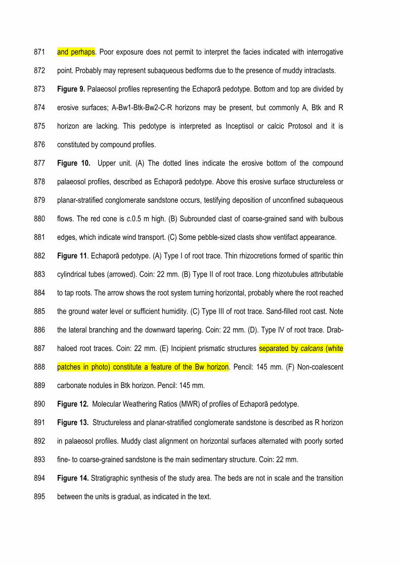
and perhaps. Poor exposure does not permit to interpret the facies indicated with interrogative 871
point. Probably may represent subaqueous bedforms due to the presence of muddy intraclasts. 872
Figure 9. Palaeosol profiles representing the Echaporã pedotype. Bottom and top are divided by 873
erosive surfaces; A-Bw1-Btk-Bw2-C-R horizons may be present, but commonly A, Btk and R 874
horizon are lacking. This pedotype is interpreted as Inceptisol or calcic Protosol and it is 875
constituted by compound profiles. 876
Figure 10. Upper unit. (A) The dotted lines indicate the erosive bottom of the compound 877
palaeosol profiles, described as Echaporã pedotype. Above this erosive surface structureless or 878
planar-stratified conglomerate sandstone occurs, testifying deposition of unconfined subaqueous 879
flows. The red cone is c.0.5 m high. (B) Subrounded clast of coarse-grained sand with bulbous 880
edges, which indicate wind transport. (C) Some pebble-sized clasts show ventifact appearance. 881
Figure 11. Echaporã pedotype. (A) Type I of root trace. Thin rhizocretions formed of sparitic thin 882
cylindrical tubes (arrowed). Coin: 22 mm. (B) Type II of root trace. Long rhizotubules attributable 883
to tap roots. The arrow shows the root system turning horizontal, probably where the root reached 884
the ground water level or sufficient humidity. (C) Type III of root trace. Sand-filled root cast. Note 885
the lateral branching and the downward tapering. Coin: 22 mm. (D). Type IV of root trace. Drab-886
haloed root traces. Coin: 22 mm. (E) Incipient prismatic structures separated by calcans (white 887
patches in photo) constitute a feature of the Bw horizon. Pencil: 145 mm. (F) Non-coalescent 888
carbonate nodules in Btk horizon. Pencil: 145 mm. 889
Figure 12. Molecular Weathering Ratios (MWR) of profiles of Echaporã pedotype. 890
Figure 13. Structureless and planar-stratified conglomerate sandstone is described as R horizon 891
in palaeosol profiles. Muddy clast alignment on horizontal surfaces alternated with poorly sorted 892
fine- to coarse-grained sandstone is the main sedimentary structure. Coin: 22 mm. 893
Figure 14. Stratigraphic synthesis of the study area. The beds are not in scale and the transition 894
between the units is gradual, as indicated in the text. 895

Figure 15. Inceptisol palaeosol profiles of upper unit of south-eastern portion of the Bauru Basin 896
are organised in cyclic sequences of compound palaeosols. Legend in Figs. 3, 7 and 12. 897
Figure 16. (A) The lower unit was deposited in a salt flat or playa-lake. The interbedding of 898
sandstone and mudstone, deformed by efflorescent salt crust growth, constitute most of the 899
depositional unit. During the floods, at the margin of the salt flat, unconfined flows formed sheet 900
delta. (B) The intermediate unit deposited in medial or distal zone of a fluvial distributary system. 901
Small and fixed ribbon-channel deposits cut prevalent interbedding of sandstone sheet and 902
muddy sandstone beds, formed by unconfined flows. Rarely, aeolian cross-stratifications can be 903
observed . 904
Figure 17. (A) The upper unit deposited by unconfined subaqueous deposits, which probably 905
partially reworked wind-transported material. (B) A relatively long period of stasis of 906
sedimentation of the order of 104 y favoured pedogenesis of the previous deposits and the 907
formation of Inceptisols. 908
Figure 18. Cartoon showing the depositional and stratigraphic evolution of the south-eastern 909
portion of the Bauru Basin. (A) Lower unit, (B) intermediate unit and (C) upper unit. See text for 910
details. 911
912
Table 1. Summary of lithofacies and pedotype observed in south-eastern portion of the Bauru 913
Group. 914
Table 2. Major and trace element data. 915
Table 3. Molecular Weathering Ratios used as palaeoenvironmental proxies in Echaporã 916
pedotype. 917
918
919

Monte Alto
Quirinópolis
SÃO PAULO
Para
ná ri
ver
Paranaiba river
Rio Grande river
Tieté river
Rio Paranapanema
Cassilândia
Marília
23º S
47º W
FIGURE 1
100 km
São Paulo
Central - SouthernBrazil
Brasília
Present study area Previous study area
Patrick
Realce
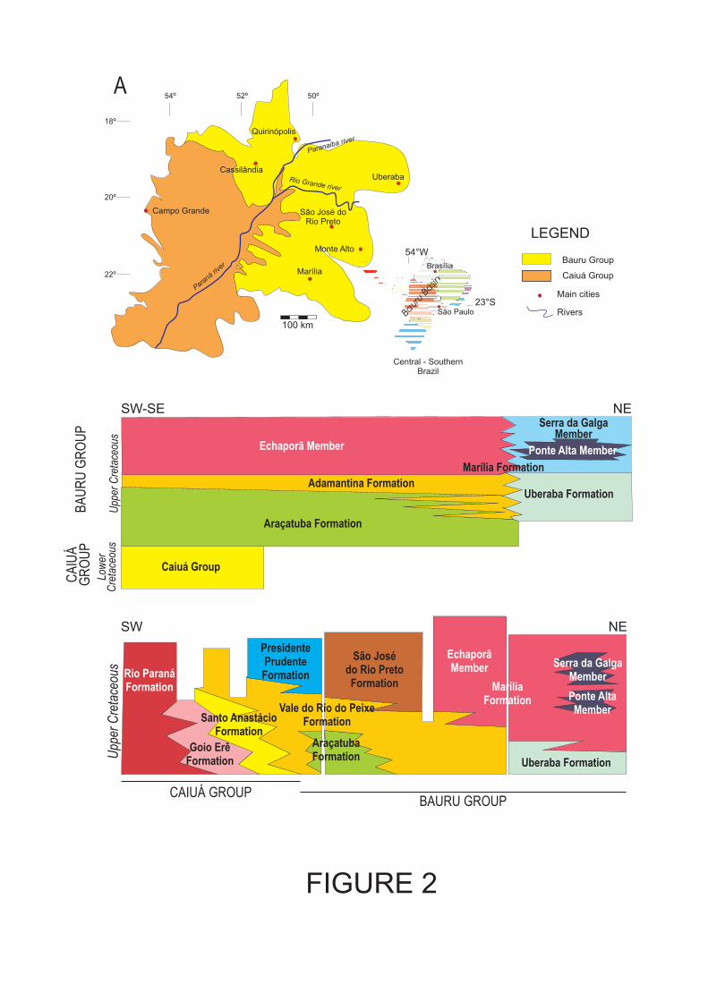
A
Main cities
Bauru Group
Rivers
LEGEND
FIGURE 2
100 km
52º 50º54º
Uberaba
Quirinópolis
São José do
Rio Preto
Campo Grande
Marília
Para
ná riv
er
Paranaiba river
Rio Grande river
Monte Alto
São Paulo
23°S
54°W
Bauru
Basin
Central - Southern
Brazil
Brasília
Caiuá Group
18º
20º
22º
Cassilândia
SW-SE NE
BA
UR
U G
RO
UP
CA
IUÁ
GR
OU
P
Araçatuba Formation
Adamantina Formation
Echaporã Member
Marília Formation
Serra da GalgaMember
Ponte Alta Member
AraçatubaFormation
Vale do Rio do PeixeFormation
Uberaba Formation
EchaporãMember Serra da Galga
MemberMarília
Formation
São Josédo Rio PretoFormation
PresidentePrudenteFormation
Santo AnastácioFormation
Rio ParanáFormation
Goio ErêFormation
Ponte AltaMember
SW NE
Uberaba Formation
Upp
er C
reta
ceou
sU
pper
Cre
tace
ous
Low
erC
reta
ceou
s
Caiuá Group
CAIUÁ GROUPBAURU GROUP
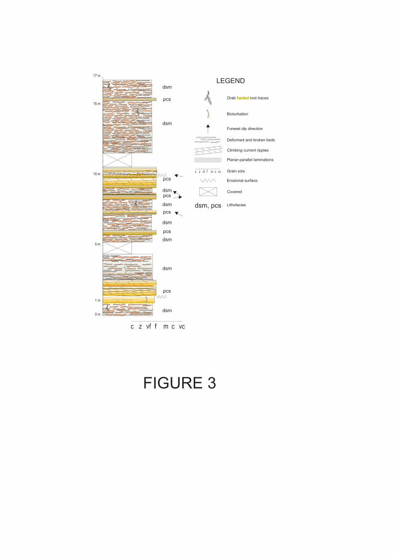
m c vc
Erosional surface
Grain sizec z vf f m c vc
Climbing current ripples
Bioturbation
Covered
Drab haoled root traces
Planar-parallel laminations
Foreset dip direction
dsm, pcs Lithofacies
dsm
pcs
FIGURE 3
10 m
15 m
17 m
0 m
1 m
5 m
LEGEND
Deformed and broken beds
dsm
dsm
dsm
dsm
dsm
dsm
dsm
pcs
pcs
pcs
pcs
pcs
Patrick
Realce

D
A
iii
C
ii
i
FIGURE 4
B
i
ii
ii
i

A
FIGURE 5
B
B
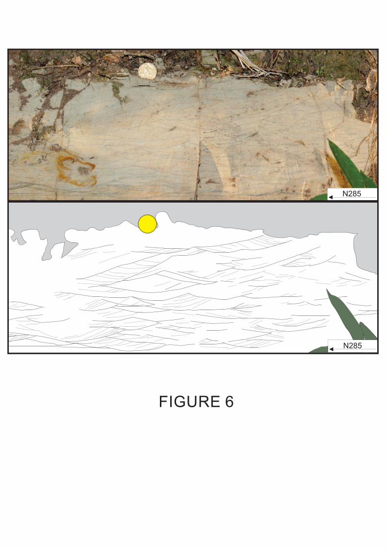
FIGURE 6
N285
N285

FIGURE 7
1 m
chs
ms
1 m
ms
ms
ms
ms
ms
msms
chs
ms
msms
ss
covered
covered
covered
covered
ss
ss
ss
ss
ssss ss
ss
ss
ss
ssss
ss
ss
ss

FIGURE 8
A
B
C
1 m
1 m
1 m
C
ss
?
css
covered
covered
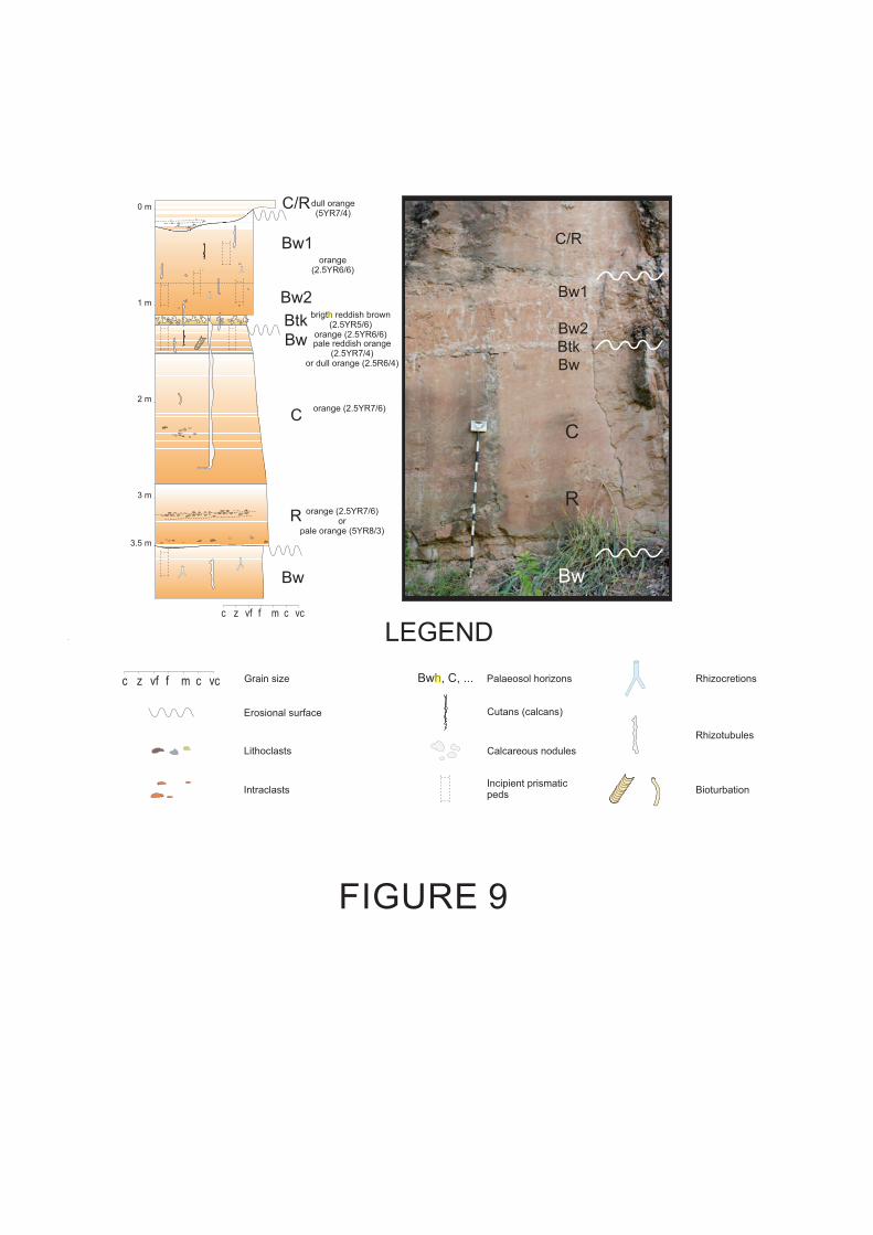
orange
( . )2 5YR6/6
1 m
0 mdull orange
( )5YR7/4
2 m
3 m
brigth reddish brown
( . )2 5YR5/6
( . )orange 2 5YR6/6
pale reddish orange
( . )2 5YR7/4
r (2.5R )o dull orange 6/4
( . )orange 2 5YR7/6
or
( )pale orange 5YR8/3
( . 7 )orange 2 5YR /6
3.5 m
R
Btk
C
Bw2
Bw1
Bw
C/R
Btk
Bw
C
Bw
Bw2
C/R
Rhizocretions
Calcareous nodules
Bioturbation
LEGEND
Erosional surface
Grain size Bwh, C, ... Palaeosol horizons
Cutans (calcans)
Rhizotubules
Intraclasts
Lithoclasts
c z vf f m c vc
Incipient prismatic
peds
FIGURE 9
c z vf f m c vc
R
Bw
Bw1
Patrick
Realce
Patrick
Realce

A
FIGURE 10
sand grain
B
100 mm
C

FIGURE 11
C D
F
A B
E
1 m

FIGURE 12
orange
( . )2 5YR6/6
1 m
c z vf f m c vc
0 m
dull orange
( )5YR7/4
2 m
3 m
brigth reddish brown
( . )2 5YR5/6
( . )orange 2 5YR6/6
pale reddish orange
( . )2 5YR7/4
r (2.5R )o dull orange 6/4
( . )orange 2 5YR7/6
or
( )pale orange 5YR8/3
( . 7 )orange 2 5YR /6
R
Btk
C
Bw2
Bw1
Bw
C
( )pale orange 5YR8/3
BA64
BA69
BA68
BA70
BA74
BA75
BA76
BA77
BA81
BA78
BA79
BA80
4 m
5 m
6 m
7 m
pale orange (5YR8/3)
or
dull orange (5YR7/3)
orange
( 6 6)5YR /Ck
R
Bw
Btk
Bw
8 m
9 m
Btk
A/Bw
BA98
BA97
BA96
BA95
BA94
BA93
BA92
BA88
BA87
BA86
BA85
BA84
reddish orange
(10R6/6)
orange
(2.5YR6/6)
orange
(2.5YR6/6)
pale orange (5YR8/3)
CBA99
BA100
bright reddish brown
(2.5YR5/8)
C
2 40 6 1
Leaching
Rb/Sr
0 0.5 400 20 0.10.05
Hydrolysis
(CaO+Na O+MgO+K O)/Al O2 2 2 3
0 10 20 30 40
C.I.A.
100xAl O /(Al O +CaO+Na O+K O)2 3 2 3 2 2
0 10050
Provenience
TiO /Al O2 2 3
0 0.20.10
Bw
Clayeyness
Al O /SiO2 3 2
Calcification
(CaO+MgO)/Al O2 3
Leaching
Ba/Sr

FIGURE 13
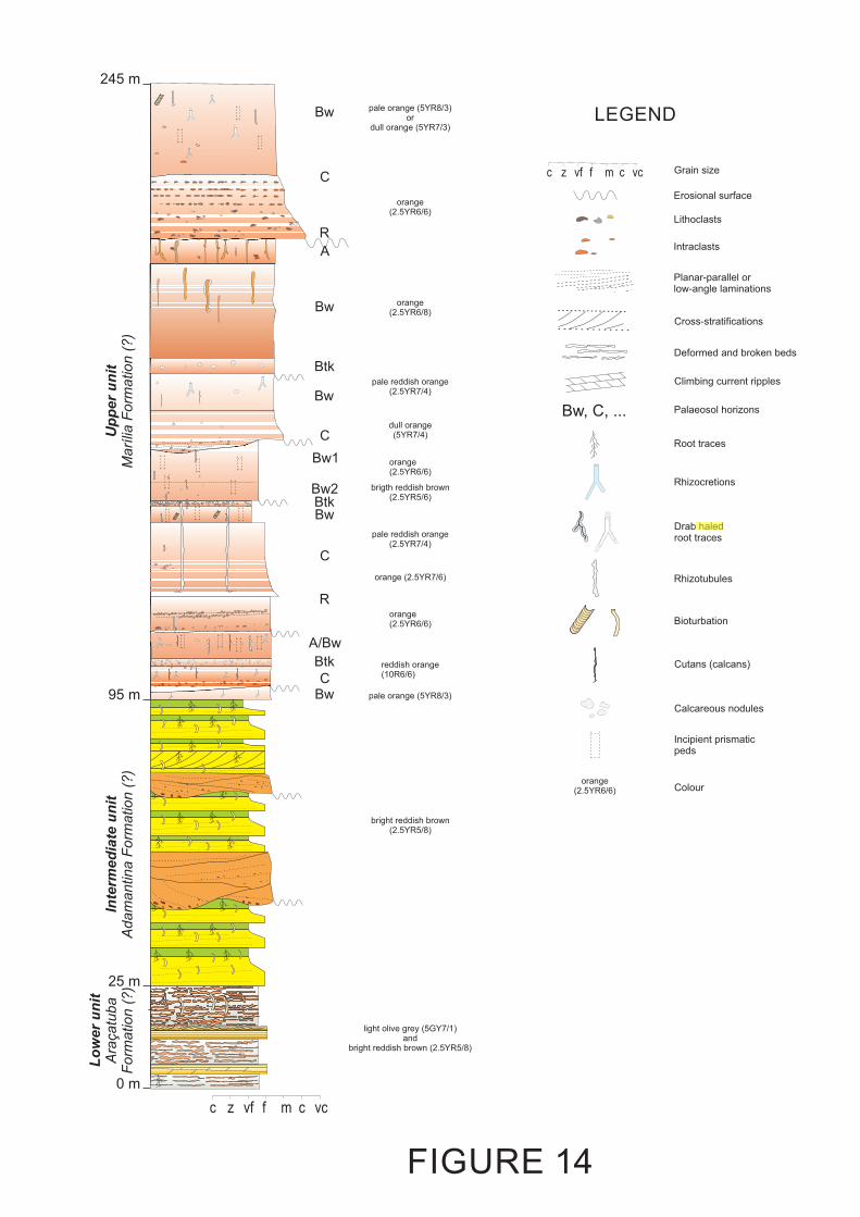
FIGURE 14
25 m
0 m
m c vc
95 m
245 m
orange
( . )2 5YR6/6
dull orange
( )5YR7/4
brigth reddish brown
( . )2 5YR5/6
pale reddish orange
( . )2 5YR7/4
( . 7 )orange 2 5YR /6
Btk
C
Bw2
Bw1
Bw
C
pale orange (5YR8/3)
or
dull orange (5YR7/3)
R
Bw
Btk
A/Bw
reddish orange
(10R6/6)
orange
(2.5YR6/6)
pale orange (5YR8/3)
C
orange
(2.5YR6/6)
orange
(2.5YR6/8)
C
R
A
Bw
Btk
Bw
pale reddish orange
( . )2 5YR7/4
Bw
Lo
wer
un
itA
raçatu
ba
Form
ation (
?)
Inte
rmed
iate
un
itA
dam
antina F
orm
ation (
?)
Up
per
un
itM
arí
lia F
orm
ation (
?)
LEGEND
Rhizocretions
Calcareous nodules
Bioturbation
Erosional surface
Grain size
Bw, C, ... Palaeosol horizons
Cutans (calcans)
Rhizotubules
Intraclasts
Lithoclasts
c z vf f m c vc
Drab haled
root traces
Incipient prismatic
peds
Root traces
Climbing current ripples
Planar-parallel or
low-angle laminations
Deformed and broken beds
Cross-stratifications
orange
(2.5YR6/6) Colour
bright reddish brown
(2.5YR5/8)
light olive grey (5GY7/1)
and
bright reddish brown (2.5YR5/8)
Patrick
Realce
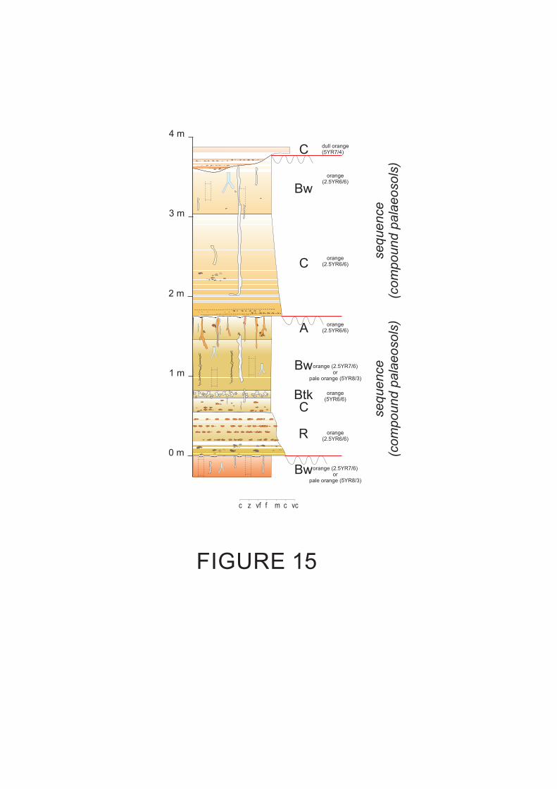
orange
( . )2 5YR6/6
dull orange
( )5YR7/4
C
Bw
C
orange
( 6 6)5YR /
C
Bw
c z vf f m c vc
orange
(2.5YR6/6)A
Btk
R
Bw
( . )orange 2 5YR7/6
or
( )pale orange 5YR8/3
( . )orange 2 5YR7/6
or
( )pale orange 5YR8/3
orange
(2.5YR6/6)
FIGURE 15
0 m
2 m
4 m
sequence
(com
pound p
ala
eosols
)
sequence
(com
pound p
ala
eosols
)
3 m
1 m
orange
(2.5YR6/6)
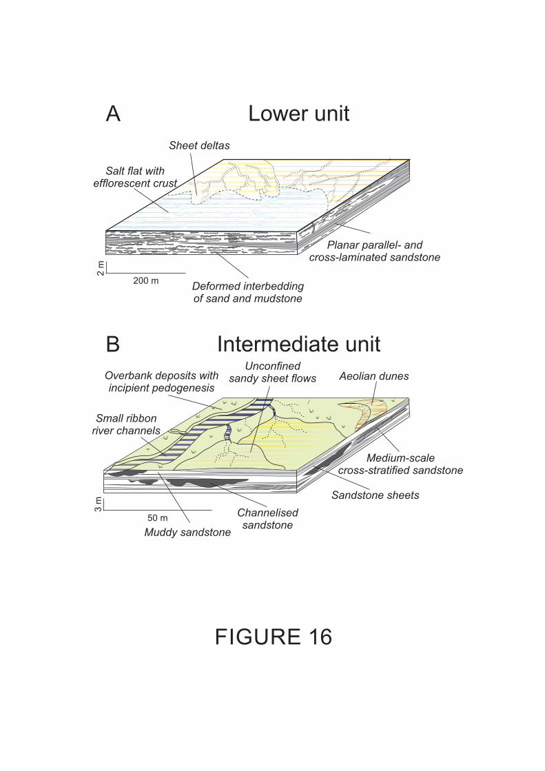
FIGURE 16
50 m
3 m
200 m
2 m
Lower unit
Intermediate unit
A
B
Sheet deltas
Planar parallel- and
cross- stonelaminated sand
Deformed interbedding
stoneof sand and mud
Salt flat with
efflorescent crust
Unconfined
sandy s flowsheet Aeolian dunes
Small ribbon
river channels
Channelised
sandstone
Sandstone sheets
Medium-scale
cross-stratified sandstone
Overbank deposits with
incipient pedogenesis
Muddy sandstone
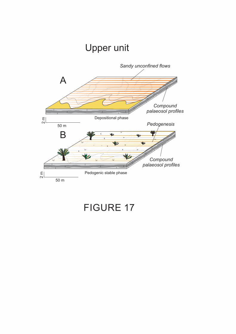
50 m
2 m
Upper unit
50 m
2 m
A
B
FIGURE 17
Pedogenic stable phase
Sandy unconfined flows
Compound
palaeosol profiles
Depositional phase
Pedogenesis
Compound
palaeosol profiles

FIGURE 18
Lower unit?
?
Intermediate unit
?
?
0 m
m c vc
95 m
245 m
Lower unit
Araçatuba Formation
Upper unit
Marília Formation
25 m
Intermediate unit
Adamantina Formation
Btk
C
Bw
C
R
Bw
Btk
C
C
R
A
Bw
Btk
Bk
Bw
Bw
Upper unit
Retrogradation
Progradation
A
B
C ?
?
0 m
m c vc
25 m
95 m
245 m
Up
per
un
itM
arí
lia F
orm
ati
on
(?
)
Btk
C
Bw
C
R
Bw
Btk
C
C
R
A
Bw
Btk
Bk
Bw
Bw
Lower unit
Araçatuba Formation
Upper unit
Marília Formation
Intermediate unit
Adamantina Formation
Btk
C
Bw
C
R
Bw
Btk
C
C
R
A
Bw
Btk
Bk
Bw
Bw
0 m
95 m
245 m
25 m
m c vc
Lower unit
Araçatuba Formation
Upper unit
Marília Formation
Intermediate unit
Adamantina Formation

Facies and palaeosols
name
Stratigraphic occurrence
Description Interpretation Figures
Deformed interbedding of sandstone and mudstone
Lower unit Irregular, broken, undulated and micro-folded interbedding of laminae or patches of well-sorted, fine- to very fine-grained weakly-cemented sandstone (olive grey - 5GY7/1) and mudstone (bright reddish brown - 2.5YR5/8) Drab-haloed root traces and bioturbation are present.
Sedimentary structures formed by growing of thin salt efflorescent crusts on a salt flat or playa-lake. Root traces and reddish colour indicate subaerial conditions.
Fig. 4
Planar parallel and cross-laminated sandstone
Lower unit Tabular beds of well-sorted, fine- and very fine-grained weakly cemented sandstone. Planar parallel laminations, climbing cross-laminations and this mudstone beds constituted small sequences in this order. Trough cross-laminations with opposite dip of the foresets are present.
Deposition by unidirectional subaqueous waning flows passing from upper to lower flow regime. These deposits formed sheet deltas at the margin of the flooded salt flat. Trough cross-laminations with opposite dip of the foresets indicate wave reworking.
Figs. 5 and 6
Muddy sandstone
Intermediate unit
Tabular muddy very fine-grained sandstone. Bioturbation and small rhizocretions are present.
Deposition by low-energy and unconfined flows in floodplain area. Root traces indicate incipient pedogenesis.
Figs. 7 and 8A
Sheet sandstone
Intermediate unit
Sheet shape beds of fine-grained sandstone, structureless or with local planar laminations.
Deposition by unconfined depositional subaqueous flows characterised by rapid deceleration of the flow and consequent deposition of sediment from suspension. Planar laminations may be related to subaqueous upper flow regime.
Figs. 7
Channelised sandstone
Intermediate unit
Ribbon shape sandstone bodies with concave-up bottom and flat top. Internally, constituted by various lenticular beds divided by concave-up erosive surfaces.
Deposition in multistorey ribbon-shape fixed channel.
Figs. 7 and 8B
Medium-scale cross-stratified sandstone
Intermediate unit
Tangential cross-stratifications of fine- and very fine-grained sandstone.
Small aeolian dunes. Fig. 8C
Echaporã pedotype
Upper unit A-Bw-(Btk)-C-R, horizons in most complete profiles. A, Btk and R horizon are in general absent. Parent material is fine- to medium-grained, moderately to well-sorted sandstone. Incipient prismatic structures and poorly developed calcium carbonate concentration are present.
Poorly developed palaeosols. Inceptisol or calcic Protosol.
Figs. 9, 10, 11 and 12
Structureless and planar-stratified conglomeratic sandstone
Upper unit Sheet beds of conglomeratic sandstone. Structureless or organised in alternating beds of sandstone and conglomerate, with pebble-sized showing a bed parallel orientation.
Unconfined subaqueous flows. Fig.13
TABLE 1

Sample
Depth m
Leaching Ba/Sr
Leaching Rb/Sr
Calcification Clay formation
Hydrolysis C.I.A. Provenience TiO2/Al2O3
BA64 0 4.42 0.74 1.31 0.03 1.68 55.6 0.13
BA68 35 3.87 0.71 1.23 0.04 1.61 58.9 0.14
BA69 80 3.87 0.67 1.26 0.04 1.61 58.6 0.15
BA70 105 2.57 0.4 1.66 0.04 2.02 46.5 0.14
BA74 125 1.07 0.01 37.3 0.06 37.5 2.71 0.12
BA75 150 3.92 0.8 1.16 0.04 1.5 67.8 0.13
BA76 180 4.28 0.63 1.12 0.03 1.51 59.1 0.08
BA77 195 4.33 0.64 0.77 0.03 1.18 64.3 0.13
BA78 235 4.64 0.64 0.71 0.03 1.12 63.7 0.11
BA79 280 4.6 0.6 0.8 0.02 1.19 62.8 0.1
BA80 310 4.11 0.59 0.6 0.02 1.02 62.9 0.11
BA81 345 4.14 0.61 0.6 0.02 1.03 62.8 0.13
BA84 380 5.12 0.89 0.99 0.03 1.41 65.9 0.13
BA86 415 4.55 0.91 0.96 0.03 1.37 65.6 0.14
BA85 425 4.89 0.89 1.01 0.03 1.42 66.7 0.13
BA87 460 1.18 0.08 6.64 0.06 6.92 14.3 0.13
BA88 495 4.67 0.87 1.02 0.03 1.42 64.8 0.14
BA92 570 5.04 0.83 1 0.03 1.42 62.7 0.13
BA93 635 4.43 0.68 1.16 0.03 1.58 57.4 0.14
BA94 650 0.9 0.1 5.5 0.05 5.82 16.8 0.13
BA95 695 4.15 0.75 1.29 0.04 1.65 54.2 0.13
BA96 735 2.5 0.35 2 0.04 2.35 39.6 0.13
BA97 815 4.87 0.67 1.16 0.03 1.55 58.3 0.12
BA98 845 0.49 0.03 16.2 0.05 16.5 6.06 0.14
BA99 870 3.65 0.66 1.23 0.04 1.55 58 0.16
BA100 905 4.07 0.59 1.19 0.03 1.56 54.7 0.12
TABLE 3

Major oxides (weight percentage)
Sample Depth m
SiO2 TiO2 Al2O3 Fe2O3 MnO MgO CaO Na2O K2O P2O5 LOI Total
BA64 0 86.65 0.427 4.35 1.63 0.016 1.51 1.03 0.19 1.19 0.042 2.9 99.9 BA68 35 83.8 0.562 5.31 1.8 0.022 1.91 0.93 0.29 1.42 0.05 3.25 99.3 BA69 80 82.45 0.697 5.75 2.28 0.02 2.06 1.12 0.28 1.45 0.058 3.49 99.6 BA70 105 80.46 0.639 5.66 2.21 0.025 1.94 2.46 0.28 1.45 0.062 4.29 99.5 BA74 125 19.55 0.205 2.1 1.1 0.14 1.32 41.25 0 0.35 0.004 33.8 99.8 BA75 150 82.97 0.596 5.97 2.28 0.021 2.43 0.44 0.3 1.42 0.055 3.44 99.9 BA76 180 87.79 0.248 4.13 1.32 0.014 1.33 0.69 0.2 1.18 0.048 2.49 99.4 BA77 195 89.44 0.387 3.87 1.57 0.021 0.96 0.31 0.18 1.19 0.041 1.74 99.7 BA78 235 90.38 0.323 3.84 1.41 0.018 0.84 0.33 0.18 1.19 0.042 1.55 100.1 BA79 280 89.87 0.29 3.68 1.29 0.02 0.87 0.41 0.16 1.08 0.036 1.71 99.4 BA80 310 91.96 0.262 3.06 1.13 0.015 0.52 0.28 0.13 1 0.033 1.27 99.6 BA81 345 91.67 0.336 3.2 1.23 0.018 0.55 0.29 0.14 1.05 0.037 1.16 99.7 BA84 380 86.93 0.457 4.38 1.51 0.015 1.54 0.24 0.2 1.39 0.037 3.14 99.8 BA86 415 86.13 0.508 4.67 1.63 0.013 1.57 0.28 0.2 1.49 0.04 3.27 99.8 BA85 425 87.15 0.443 4.36 1.52 0.015 1.59 0.22 0.15 1.41 0.04 3.14 100 BA87 460 54.86 0.521 5.26 2.34 0.125 1.93 16.54 0.11 1.19 0.044 16.8 99.7 BA88 495 86.57 0.494 4.59 1.7 0.014 1.6 0.34 0.18 1.46 0.041 3.33 100.3 BA92 570 87.37 0.442 4.21 1.4 0.017 1.38 0.39 0.17 1.4 0.039 2.93 99.7 BA93 635 86.03 0.495 4.53 1.65 0.021 1.5 0.8 0.21 1.44 0.042 3.47 100.2 BA94 650 62.18 0.534 5.12 2.13 0.044 1.73 13.07 0.17 1.29 0.055 13.6 99.9 BA95 695 80.92 0.598 6.04 2.38 0.019 1.92 1.6 0.29 1.58 0.058 5 100.4 BA96 735 80.91 0.585 5.67 2.32 0.038 1.84 3.67 0.24 1.47 0.052 2.8 99.6 BA97 815 86.18 0.435 4.58 1.61 0.015 1.51 0.82 0.22 1.31 0.045 3.52 100.3 BA98 845 38.79 0.376 3.37 1.51 0.068 1.34 28.18 0.14 0.69 0.06 24.9 99.4 BA99 870 82.01 0.663 5.3 2.51 0.023 1.73 1.17 0.22 1.25 0.06 4.34 99.3
BA100 905 85.53 0.412 4.54 1.76 0.014 1.31 1.16 0.17 1.27 0.049 3.75 100
Trace elements (ppm) Sample Depth
m Ba Ce Cr Cu Ga La Nb Nd Ni Pb Rb Sc Sr Th V Y
Zn
Zr BA64 0 319 24 42 3.4 3.7 14 10 10 8.1 8 33 5 46 2.6 51 6.6 14.4 172
BA68 35 340 27 61 4.5 5.9 15 15 16 12.7 10.9 39 6 56 5.1 56 7.5 19.7 188
BA69 80 370 36 87 5.4 5 <13 18.4 15 13.5 9.4 40 9 61 5 61 8.6 22.2 222
BA70 105 390 35 206 4.2 4.4 18 17.5 22 12.4 11.2 38 7 97 4.3 65 9.2 22.4 208
BA74 125 704 17 12.9 <1.5 4.4 31 6.6 <8 9.9 17.5 4.2 16 418 <2 33 19.9 10.8 54
BA75 150 307 36 46 4.9 6 18 13.3 21 12.9 9.1 39 10 50 5.8 71 8.7 20.5 205
BA76 180 349 16 19.7 4.1 4.9 13 8 <8 8.3 7.3 32 5 52 4.3 41 5.9 14.2 100
BA77 195 346 20 39 3.6 2.7 14 8.8 16 8.2 9.1 32 4 51 5.9 49 5.7 13.8 125
BA78 235 371 24 90 2.3 3 16 7.8 <8 7.8 8.9 32 4 51 3.6 53 5 15.9 104
BA79 280 368 20 155 2 2.6 19 7.9 10 8.5 9.4 30 5 51 2.9 64 5.6 14.4 99
BA80 310 309 11 62 3.1 <2 <13 7 <8 5 7.4 27.7 <3 48 <2 36 6.3 10 107
BA81 345 318 14 51 3 3.3 <13 8.1 8 6.3 8.8 29.4 <3 49 2.3 48 6.2 11.8 110
BA84 380 353 16 57 3.4 6.2 15 14.5 17 9.7 10.4 38 4.5 44 3.5 43 7.4 15.2 190
BA86 415 328 24 45 4.8 6.3 16 15.7 21 10.1 10 41 3.3 46 5.4 46 8.5 14.6 210
BA85 425 345 23 32 4.7 6.1 17 13.6 13 9.9 10.3 39 4.7 45 6 43 8.4 14 183
BA87 460 798 50 41 4.5 7 38 19.8 31 17 24.7 33 9 430 5.6 56 18.5 23.8 153
BA88 495 344 30 39 5.3 6.4 16 14.9 12 9.8 10.8 40 3.3 47 4.2 50 7.7 14.8 201
BA92 570 371 18 34 3.5 4.6 21 14 14 8.1 10.6 38 5.3 47 4.9 48 6.1 14.4 194
BA93 635 410 22 35 4.5 5.9 16 15.5 15 9.1 12.4 39 4.3 59 4.6 52 7.7 15.1 195
BA94 650 487 41 41 4.6 6.3 39 21.6 23 14.8 15.4 35 9.9 345 5.2 61 13.5 24.5 182
BA95 695 410 25 42 8.2 8.8 19 18.7 26 14.6 10.1 46 5.7 63 4.5 73 10.9 24 224
BA96 735 475 36 44 7.7 7.5 26 18.4 33 13.4 13 41 5.1 121 5.9 73 12 23.1 203
BA97 815 420 18 36 4.6 5.9 16 13.1 <11 9.3 10.1 36 3.3 55 4.4 55 7.2 16 171
BA98 845 472 38 21 <1 5.2 32 12.7 21 10.3 13.8 15.8 10.9 611 3.4 30 13.5 17 143
BA99 870 320 31 60 5.7 7 19 14.6 26 13.6 11.3 36 5.1 56 5 79 10.4 21 285
BA100 905 364 17 36 3.9 6.1 10 10.9 11 10.5 9.1 33 4.6 57 2.7 57 6.9 16.7 159
TABLE 2