Versão traduzida de USB Protocolo completo
112
Versão traduzida de USB Protocolo completo.pdf Página 1 Universal Serial Bus Especificação Compaq Hewlett-Packard Intel Brilhante Microsoft NEC Philips Revisão 2.0 27 de abril de 2000 Página 2 Especificações Universal Serial Bus Revisão 2.0 ii Âmbito desta Revisão A revisão 2.0 da especificação destina-se ao design de produto. Todos os esforços foram feito s para garantir uma especificação consistente e implementável. Implementações devem assegurar o cumprimento desta revisão. Histórico da Revisão Revisão Data de Emissão Comentários 0,7 11 de novembro de 1994 Substitui 0.6e. 0,8 30 de dezembro de 1994 Revisões para os capítulos 3-8, 10 e 11. Adicionado apêndices. 0,9 13 abr 1995 Revisões a todos os capítulos. 0,99 25 de agosto de 1995 Revisões a todos os capítulos. 1,0 FDR 13 de novembro de 1995 Revisões para os capítulos 1, 2, 5-11. 1,0 15 jan 1996 Edições em capítulos 5, 6, 7, 8, 9, 10 e 11 para consistência. 1,1 23 de setembro de 1998 Atualizações para todos os capítulos para corrigir problemas identificados. 2.0 (projecto 0,79) 05 de outubro de 1999 Revisões para os capítulos 5, 7, 8, 9, 11 para adicionar alta velocidade. 2.0 (projecto 0.9) 21 de dezembro de 1999 Revisões de todos os capítulos para adicionar alta ve locidade. 2,0 27 de abril de 2000 As revisões de modo de alta v elocidade. Especificações Universal Serial Bus Copyright © 2000, Compaq Computer Corporation, Hewlett-Packard Company, Intel Corporation, Lucent Technologies Inc, Microsoft Cor poration , NEC Corporation, Konin klijke Phili ps Electr onics NV Todos os direitos reservados. PROPRIEDADE INTELECTUAL AVISO LEGAL Esta especificação é FORNECIDO "COMO ESTÁ", SEM GARANTIAS DE QUALQUER ESPÉCIE, INCLUINDO QUALQUER GARANTIA DE COMERCIALIZAÇÃO, NÃO-VIOLAÇÃO OU ADEQUAÇÃO A QUALQUER PROPÓSITO PARTICULAR. Os autores deste ESPECIFICAÇÃO qualquer responsabilidade, INCLUSIVE RESPONSABILIDADE POR INFRAÇÃO DE quaisquer direitos de propriedade, RELACIONADAS AO USO OU IMPLEMENTA ÇÃO DE INFORMAÇÕE S nesta especifica ção. O FORNECIMEN TO DESTE ESPECIFICAÇÃO PARA VOCÊ NÃO l he fornecer qualquer LICENÇA, EXPRESSA OU IMPLÍCITA, POR EMBARGO OU DE OUTRA FORMA, A QUALQUER DIREITO DE PROPRIEDADE INTELECTUAL. Todos os nomes de produtos são marcas comerciais, marcas registradas ou marcas de serviços da seus respectivos proprietários.
-
Upload
daniel-jean -
Category
Documents
-
view
75 -
download
0
Transcript of Versão traduzida de USB Protocolo completo

5/8/2018 Versão traduzida de USB Protocolo completo - slidepdf.com
http://slidepdf.com/reader/full/versao-traduzida-de-usb-protocolo-completo 1/112
Versão traduzida de USB Protocolo completo.pdf
Página 1
Universal Serial BusEspecificaçãoCompaqHewlett-PackardIntelBrilhanteMicrosoft
NECPhilipsRevisão 2.027 de abril de 2000
Página 2
Especificações Universal Serial Bus Revisão 2.0iiÂmbito desta RevisãoA revisão 2.0 da especificação destina-se ao design de produto. Todos os esforços foram feitos paragarantir umaespecificação consistente e implementável. Implementações devem assegurar o cumprimento desta revisão.Histórico da RevisãoRevisãoData de EmissãoComentários
0,711 de novembro de 1994Substitui 0.6e.0,830 de dezembro de 1994Revisões para os capítulos 3-8, 10 e 11. Adicionadoapêndices.0,913 abr 1995Revisões a todos os capítulos.0,9925 de agosto de 1995Revisões a todos os capítulos.1,0 FDR13 de novembro de 1995Revisões para os capítulos 1, 2, 5-11.1,0
15 jan 1996Edições em capítulos 5, 6, 7, 8, 9, 10 e 11 paraconsistência.1,123 de setembro de 1998Atualizações para todos os capítulos para corrigir problemas identificados.2.0 (projecto 0,79) 05 de outubro de 1999Revisões para os capítulos 5, 7, 8, 9, 11 para adicionar altavelocidade.2.0 (projecto 0.9)21 de dezembro de 1999Revisões de todos os capítulos para adicionar alta velocidade.2,027 de abril de 2000As revisões de modo de alta velocidade.Especificações Universal Serial BusCopyright © 2000, Compaq Computer Corporation,
Hewlett-Packard Company, Intel Corporation, Lucent Technologies Inc,Microsoft Corporation, NEC Corporation, Koninklijke Philips Electronics NVTodos os direitos reservados.PROPRIEDADE INTELECTUAL AVISO LEGALEsta especificação é FORNECIDO "COMO ESTÁ", SEM GARANTIAS DE QUALQUER ESPÉCIE,INCLUINDO QUALQUER GARANTIA DE COMERCIALIZAÇÃO, NÃO-VIOLAÇÃO OU ADEQUAÇÃO AQUALQUER PROPÓSITO PARTICULAR. Os autores deste ESPECIFICAÇÃO qualquer responsabilidade,INCLUSIVE RESPONSABILIDADE POR INFRAÇÃO DE quaisquer direitos de propriedade, RELACIONADAS AO USOOU IMPLEMENTAÇÃO DE INFORMAÇÕES nesta especificação. O FORNECIMENTO DESTEESPECIFICAÇÃO PARA VOCÊ NÃO lhe fornecer qualquer LICENÇA, EXPRESSA OU IMPLÍCITA,POR EMBARGO OU DE OUTRA FORMA, A QUALQUER DIREITO DE PROPRIEDADE INTELECTUAL.Todos os nomes de produtos são marcas comerciais, marcas registradas ou marcas de serviços da seusrespectivos proprietários.

5/8/2018 Versão traduzida de USB Protocolo completo - slidepdf.com
http://slidepdf.com/reader/full/versao-traduzida-de-usb-protocolo-completo 2/112
Por favor envie comentários via correio eletrônico par a techsup@usb .org
P ar a obter inform ações do setor , consulte a págin a web do USB Implementers Forum em http://www .usb .org
Página 3
Especificações Universal Serial Bus Revisão 2.0iiiAviso de USB 2.0 Contribuição TécnicaOs autores desta especificação gostaria de reconhecer as seguintes pessoas que participaram do USBPromotor 2,0 Grupo grupos técnicos de trabalho. Gostaríamos também de agradecer a outros na USB 2.0Promotor e empresas em toda a indústria, que contribuíram para o desenvolvimento desta especificação.Hub Grupo de TrabalhoJohn GarneyIntel Corporation (Presidente Editor / )Ken StufflebeamCompaq Computer CorporationDavid WootenCompaq Computer CorporationMatt NiebergerHewlett-Packard CompanyJohn HowardIntel CorporationVenkat IyerIntel CorporationSteve McGowanIntel CorporationGeert KnapenRoyal Philips ElectronicsZong Liang WuRoyal Philips ElectronicsJim CleeLucent Technologies IncJim GuziakLucent Technologies IncDave ThompsonLucent Technologies IncJohn FullerMicrosoft CorporationNathan ShermanMicrosoft CorporationMark WilliamsMicrosoft CorporationNobuo Furuya
NEC CorporationToshimi SakuraiNEC CorporationMoto SatoNEC CorporationKatsuya SuzukiNEC CorporationGrupo de Trabalho elétricaJon LuekerIntel Corporation (Presidente Editor / )David WootenCompaq Computer CorporationMatt NiebergerHewlett-Packard CompanyLarry TaugherHewlett-Packard CompanyVenkat Iyer
Intel CorporationSteve McGowanIntel CorporationMike PennellIntel CorporationTodd OesteIntel CorporationGerrit den BestenRoyal Philips ElectronicsMarq KoleRoyal Philips ElectronicsZong Liang WuRoyal Philips Electronics

5/8/2018 Versão traduzida de USB Protocolo completo - slidepdf.com
http://slidepdf.com/reader/full/versao-traduzida-de-usb-protocolo-completo 3/112
Jim CleeLucent Technologies IncJim GuziakLucent Technologies IncPar ParikhLucent Technologies IncDave ThompsonLucent Technologies IncEd Giaimo
Microsoft CorporationMark WilliamsMicrosoft CorporationToshihiko OhtaniNEC CorporationKugao OuchiNEC CorporationKatsuya SuzukiNEC CorporationToshio TasakiNEC Corporation
Página 4
Especificações Universal Serial Bus Revisão 2.0iv
Página 5
Especificações Universal Serial Bus Revisão 2.0vConteúdoCAPÍTULO 1 INTRODUÇÃO1,111,2Objetivo da Especificação 11,3Âmbito do 21,4USB Conformidade de Produtos 21,5Documento 2CAPÍTULO 2 TERMOS E ABREVIAÇÕESCAPÍTULO FUNDO 3
3,1Metas para o Universal Serial Bus 113,2Taxonomia de Aplicação 123,3Característica 13Visão geral do capítulo 4 ARQUITETURA4,1USB Descrição do Sistema 154.1.1Ônibus (BUS) 164,2Interface física 174.2.1174.2.2Mecânico 18
4,3184.3.1Distribuição de Energia 184.3.2Poder 184,4Ônibus (BUS) 184,5194.5.1Erro 194.5.2
5/8/2018 Versão traduzida de USB Protocolo completo - slidepdf.com
http://slidepdf.com/reader/full/versao-traduzida-de-usb-protocolo-completo 4/112
Erro 194,6Sistema 194.6.1Fixação de USB 204.6.2Remoção de USB 204.6.3Ônibus 20
Página 6
Especificações Universal Serial Bus Revisão 2.0vi4,7Fluxo de Dados4.7.1Controle4.7.2Massa4.7.3Interromper4.7.4Transferências isócrono4.7.5Alocação USB4,8Dispositivos USB4.8.1Dispositivo4.8.2Descrições dispositivo4,9USB Host: Hardware e4,10 ArchitecturalCAPÍTULO 5 USB MODELO DE FLUXO DE DADOS5,1Implementador5,2Topologia Bus5.2.1Host USB5.2.2
Dispositivos USB5.2.3Bus física5.2.4Bus lógica5.2.5Software cliente-para-função5,3Fluxo de comunicação USB5.3.1Endpoints dispositivo5.3.25.3.3Quadros e5,4Transferência5.4.1
Cálculo tabela5,5Controle5.5.1Transfer Control Data Format5.5.2Transfer Control5.5.3Controle de tamanho de pacote de transferência5.5.4O controle de acesso Bus Transferência5.5.5Transferência de dados de controle

5/8/2018 Versão traduzida de USB Protocolo completo - slidepdf.com
http://slidepdf.com/reader/full/versao-traduzida-de-usb-protocolo-completo 5/112
5,6Isócrono5.6.1Transferência de dados isócrono5.6.2Transferência isócrona5.6.3Isócrono Transferência restrições de tamanho de pacote ................................................................................ 44
5.6.4Acesso isócrono Transferência restrições Bus ................................................................................ 475.6.5Transferência de dados isócrono5,7Transferências de interrupção5.7.1Interromper Formato de Transferência de Dados5.7.2Interromper a direção da transferência5.7.3Restrições de Transferência de interromper Packet Size ...................................................................................... 485.7.4Interromper Restrições de Transferência de acesso ao barramento............................................. ......................................... 49
5.7.5Interromper a transferência de dados
Página 7
Especificações Universal Serial Bus Revisão 2.0vii5,8Transferências em massa 525.8.1Transferência de dados em massa 525.8.2Transferência em bloco 525.8.3Granel Transferência restrições de tamanho de pacote ........................................................................................... 535.8.4
Transferência de massa Restrições de acesso ............................................. Bus.............................................. 535.8.5Sequências de dados em massa de Transferência 555,9De alta velocidade, pontos de extremidade de banda alta ........................................................................................... 565.9.1Endpoints interrupção de alta largura de banda ............................................................................................. 565.9.2Endpoints isócronos alta largura de banda ........................................................................................ 57Dividir 5,10 58Acesso para 5,11 Bus 585.11.1 Transferência 595.11.2 Transaction 61
5.11.3 Calculando transação Bus 635.11.4 Calculando o tamanho do buffer em Funções e Software ...................................................................... 655.11.5 Recuperação Bandwidth Bus 655,12 Considerações especiais para transferências isócronos ........................................................................... 65Aplicação isócronos 5.12.1 Exemplo não-USB ................................................................................. 665.12.2 Modelo Relógio USB 695.12.3 A sincronização do relógio 715.12.4 isócronos 715.12.5 Dados Prebuffering 805.12.6 Acompanhamento SOF 81

5/8/2018 Versão traduzida de USB Protocolo completo - slidepdf.com
http://slidepdf.com/reader/full/versao-traduzida-de-usb-protocolo-completo 6/112
5.12.7 Erro 815.12.8 Buffering para Matching Taxa 82CAPÍTULO 6 MECÂNICA6,1Arquitetônico 856,2Conector com chave 856,386
6,4Cabo 866.4.1Padrão de cabos destacável ......................................................................................... 866.4.2High-/ full-speed de cabos Captive ................................................................................... 886.4.3Baixa velocidade de cabos Captive ........................................................................................... 906.4.4Cabo proibida 926,5Conector de configuração Mecânica e Material Requirements ................................................ 936.5.1
Ícone USB 936.5.2Dados Rescisão USB Connector ................................................................................................ . 946.5.3Série "A" Série e "B" Os recipientes .......................................................................................... 946.5.4Série "A" Série e "B" Plugs .......................................................................................... .......... 98
Página 8
Especificações Universal Serial Bus Revisão 2.0viii6,6Cabo de configuração Mecânica e Material Requirements ............................................
.......... 1026.6.16.6.26.6.3Elétrico6.1.4Características cabo Ambiental ............................................................................................ 1066.1.5Listagem6,7Standards Compliance Elétrica, Mecânica, Meio Ambiente e .......................................... ...1066.7.1Documentos aplicável6,8Aterramento USB
6,9PCB ReferênciaCAPÍTULO 7 ELÉTRICA7,17.1.1Driver USB7.1.2Dados Ascensão e queda de sinal, Padrões Eye ........................................................................................ 1297.1.3Cabo7.1.4Destinatário

5/8/2018 Versão traduzida de USB Protocolo completo - slidepdf.com
http://slidepdf.com/reader/full/versao-traduzida-de-usb-protocolo-completo 7/112
7.1.5Identificação Velocidade do Dispositivo7.1.6Entrada7.1.7Sinalização7.1.8Dados Encoding / Decoding7.1.9
Bocado7.1.10 padrão de sincronização7.1.11 Dados de Sinalização7.1.12 Intervalo de quadros7.1.13 Data Source7.1.14 Sinalização Hub Timings7.1.15 Receiver Jitter Dados7.1.16 Cabo7.1.17 Cabo7.1.18 Turn-around Bus Tempo e Inter-packet Delay ............................................................................. 1687.1.19 Sinal de Fim-de-final máxima7.1.20 Modo de Teste7,2Distribuição de Energia7.2.1Classes de
7.2.2Orçamento queda de tensão7.2.3Controle de energia durante7.2.4Anexar e dinâmica7,3Físico7.3.1Regulamentares7.3.2Tempo Bus / Elétrica7.3.3Formas de onda de tempo
Página 9
Especificações Universal Serial Bus Revisão 2.0ixCAPÍTULO 8 CAMADA DE PROTOCOLO8,1Byte / Bit Ordenação 1958,2SYNC 1958,3Campo de pacotes 1958.3.1Campo Identificador de pacotes 1958.3.2Endereço 1978.3.3Número de quadros 1978.3.4Campo de dados 197
8.3.5Redundância Cíclica 1988,4Formatos de pacotes 1998.4.1Símbolo 1998.4.2Pacotes especiais dividir Transaction token ...................................................................................... 1998.4.3Start-de-Frame 2048.4.4Os pacotes de dados 206

5/8/2018 Versão traduzida de USB Protocolo completo - slidepdf.com
http://slidepdf.com/reader/full/versao-traduzida-de-usb-protocolo-completo 8/112
8.4.5Aperto de mão 2068.4.6Respostas aperto de mão 2078,5Packet transação 2098.5.1NAK Limitando via Controle de Fluxo Ping .......................................................................................... 217
8.5.2Massa 2218.5.3Controle 2258.5.4Interromper 2288.5.5Isócrono 2298,6Alternar os dados de sincronização e Retry ......................................................................................... 2328.6.1Inicialização via Token CONFIGURAÇÃO ................................................................................................ ... 2338.6.2Dados de sucesso 2338.6.3
Dados corrompidos ou Não 2338.6.4Corrompido ACK 2348.6.5Baixa velocidade 2358,7Detecção de erro e 2368.7.1Erro de pacotes 2368.7.2Bus Turn-around 2378.7.3PÕES falsa 2378.7.4Babble e Perda de recuperação da atividade ......................................................................................... 238
Página 10
Especificações Universal Serial Bus Revisão 2.0xCAPÍTULO 9 QUADRO DEVICE USB9,1Dispositivo USB9.1.1Dispositivo visível9.1.2Ônibus9,2Operações de dispositivo genérico USB9.2.1Anexo dinâmica e9.2.2Endereço
9.2.3Configuração9.2.4Dados9.2.5Poder9.2.6Pedido9.2.7Erro pedido9,3Dispositivo USB9.3.1

5/8/2018 Versão traduzida de USB Protocolo completo - slidepdf.com
http://slidepdf.com/reader/full/versao-traduzida-de-usb-protocolo-completo 9/112
9.3.29.3.3wValue9.3.49.3.59,4Os pedidos de dispositivo padrão9.4.1Recurso clara
9.4.2Obter9.4.3Obter Descriptor9.4.4Obter9.4.5Obter o status9.4.6Conjunto9.4.7Conjunto de Configuração9.4.8Conjunto9.4.9Conjunto9.4.10 Set
9.4.11 Synch9,5Descritores9,6Padrão USB Descriptor9.6.1Dispositivo9.6.29.6.3Configuração9.6.49.6.59.6.69.6.79,7Classe de Dispositivo9.7.1
Descritores9.7.2Interface (s) e Uso Endpoint9.7.3Pedidos
Página 11
Especificações Universal Serial Bus Revisão 2.0xiCAPÍTULO 10 HOST USB: HARDWARE E SOFTWARE10,1 Visão geral do Host USB 27510.1.1 27510.1.2 Controle 27810.1.3 Dados 27810.1.4 Coleta de Estado e Estatística Atividade ....................................................................................... 279
10.1.5 Interface Elétrica 27910,2 Anfitrião Requisitos Controlador 27910.2.1 Estado 28010.2.2 Serializer / Deserializer 28010.2.3 Frame e Geração Microframe ............................................................................................. . 28010.2.4 Dados 28110.2.5 Protocolo 28110.2.6 Tratamento de erros de transmissão 28210.2.7 Wakeup remoto 28210.2.8 Root Hub 28210.2.9 Sistema Anfitrião 28310,3 Visão de Software 283
5/8/2018 Versão traduzida de USB Protocolo completo - slidepdf.com
http://slidepdf.com/reader/full/versao-traduzida-de-usb-protocolo-completo 10/112
10.3.1 Configuração de Dispositivo 28310.3.2 Gestão de Recursos 28510.3.3 transferências de dados 28610.3.4 Dados Comum 28610,4 Host Controller 28710,5 Universal Serial Bus 28710.5.1 USBD 28810.5.2 Requisitos USBD Mecanismo de comando ............................................................................... 289
10.5.3 Tubo USBD 29110.5.4 Gerenciando o USB através dos mecanismos USBD ........................................................................... 29310.5.5 Passando USB Controle Preboot para o Sistema Operacional ............................................................... 29510,6 Ambiente Operacional do Sistema Guias .......................................................................................... 296CAPÍTULO ESPECIFICAÇÃO HUB 1111,1 29711.1.1 Hub 29711.1.2 Hub 29811,2 Hub Frame / Microframe 30011.2.1 alta velocidade Temporizador Faixa de Microframe .......................................................................................... 30011.2.2 Temporizador Full Frame velocidade 30111.2.3 Frame / Sincronização Temporizador Microframe .................................................................................. 301
11.2.4 Microframe Jitter relacionadas ao quadro Jitter ..................................................................................... 30311.2.5 EOF1 e EOF2 Tempo 303
Página 12
Especificações Universal Serial Bus Revisão 2.0xii11,3Comportamento acolhimento em11.3.1 Anfitrião Últimas Full-/ low-speed11.3.2 Packet Full-/ low-speed11.3.3 Full-/ low-speed Previsão de conclusão da transação ..................................................................... 30611,4 porta interna11.4.111.4.2 Suspender
11.4.3 Suspender total11.4.4 Gerar Currículo (GResume)11,5 Downstream Facing11.5.1 Downstream Enfrentando Descrições Estado do porto ................................................................................. 31211.5.2 Desconexão Detect11.5.3 Porto11,6 Upstream Facing11.6.111.6.2 alta velocidade11.6.311.6.4 Transmissor11,7 Hub11.7.1 Conectividade Packet alta velocidade11.7.2 Estado Repetidor Hub11.7.3 aguarda o início do pacote de Upstream Port (WFSOPFU) .......................................................... 329
11.7.4 Aguarde End of Packet de Upstream Port (WFEOPFU )........................................................... 33011.7.5 aguarda o início de Packet11.7.6 Aguarde End of PacketAvaliação 11,8 Estado Bus11.8.1 Porto11.8.2 Velocidade11.8.311.8.4 porta de baixa velocidadeSuspender e 11,9Redefinir 11,10 Hub11,11 Poder Port Hub11.11.1 Múltiplos

5/8/2018 Versão traduzida de USB Protocolo completo - slidepdf.com
http://slidepdf.com/reader/full/versao-traduzida-de-usb-protocolo-completo 11/112
11,12 Controller Hub11.12.1 Organização Endpoint11.12.2 Arquitetura da Informação Hub e Operação ............................................................................... 33711.12.3 Informações Alterar Porto11.12.4 Hub e Port Mudança de Status11.12.5 Relatórios Over-corrente e Recuperação .......................................................................................... 33911.12.6 Tratamento de Enumeração
Configuração 11,13 Hub
Página 13
Especificações Universal Serial Bus Revisão 2.0xiii11,14Transação 34211.14.1 34211.14.2 Tradutor Transaction 34411,15 Notation transação de divisão 34611,16 Common Dividir Estado Machines Transaction .................................................................................... 34911.16.1 Anfitrião Máquina de Estado Controlador 35011.16.2 Transação Máquina de Estado Tradutor .......................................................................................... 35411,17 Bulk / Visão geral do controle Tradução Transaction ........................................................................... 36011.17.1 Bulk / Controle seqüências transação de divisão ................................................................................... 36011.17.2 Bulk / Controle de Máquinas de Estado Dividir Transaction ........................................................................... 36611.17.3 Seqüenciamento Bulk / Controle 37111.17.4 Requisitos Bulk / Controle Buffering ......................................................................................... 37211.17.5 Outros granel / Control 372Pipelining 11,18 Transaction periódica Split e Gerenciamento de buffer.......................................... .......... 372Melhor 11.18.1 Caso Orçamento Full-Speed 37311.18.2 TT Microframe 37311.18.3 Geração de Full-speed Frames ........................................................................................... ...... 37411.18.4 Anfitrião Dividir Requisitos Scheduling Transaction ........................................................................ 374
11.18.5 Response TT 37811.18.6 TT Requisitos Handling periódica Transaction ........................................................................ 37911.18.7 Transação TT 38011.18.8 TT Completa-split Searching Estado Transaction ........................................................................... 38111,19 buffer espaço aproximado de TT Obrigatório ........................................................................................ 382Resumo 11,20 Tradução de interrupção de transações ................................................................................. 38211.20.1 Sequências Transaction interrupção Dividir .......................................................................................... 38311.20.2 Interrupção Dividir Máquinas de Estado Transaction .................................................................................. 38611.20.3 Interrupção OUT Seqüenciamento 39211.20.4 Interrupção no seqüenciamento 39311,21 Resumo Tradução isócronos Transaction .............................................
............................... 39411.21.1 Sequências Transaction isócronos Dividir ...........................................
......................................... 39511.21.2 isócronos Dividir Estado Machines Transaction ............................................................................. 39811.21.3 isócronos OUT 40311.21.4 isócronos IN 40411,22 erro TT 40411.22.1 Perda de sincronização com o TT sofs HS ................................................................................ 40411.22.2 TT Frame e requisitos de sincronização Microframe Temporizador........................................ ...... 405Descritores 11,23 407

5/8/2018 Versão traduzida de USB Protocolo completo - slidepdf.com
http://slidepdf.com/reader/full/versao-traduzida-de-usb-protocolo-completo 12/112
11.23.1 Descritores padrão para Classe Hub ............................................................................................ . 40711.23.2 classe específica Descritores 41711,24 41911.24.1 Os pedidos Padrão 41911.24.2 Os pedidos de classe específico 420
Página 14
Especificações Universal Serial Bus Revisão 2.0xivEXEMPLOS APÊNDICE A TRANSAÇÃOA.1 Bulk / OUT de Controle e exemplos de transação CONFIGURAÇÃO .................................................................. 439A.2 Bulk / Controle Na transaçãoA.3 Interrupt OUT TransactionA.4 Exemplos de interrupção no Transaction ............................................................................................. .... 509A.5 isócronos OUT SpAppendix A Exemplos de transaçõesAPÊNDICE B DECLARAÇÕES EXEMPLO PARA MÁQUINAS DE ESTADOB.1 globalB.2 Host ControllerB.3 Tradutor TransactionAPÊNDICE C estado RESET DIAGRAMAS PROTOCOLOC.1 Diagrama de Estado Downstream Enfrentando Porto .......................................................................................... 565C.2 Estado do porto Upstream FacingC.2.1Redefinir De SuspensoC.2.2Redefinir De Full-speed Estado não suspensos ................................................................................ 570C.2.3Redefinir De alta velocidade Estado não suspensos .............................................................................. 570C.2.4Redefinir HandshakeINDEX
Página 15
Especificações Universal Serial Bus Revisão 2.0xvFiguras
Figura 3-1. Taxonomia Espaço aplicaçãoFigura 4-1. ÔnibusFigura 4-2. USBFigura 4-3. Um típicoFigura 4-4. Hubs em um ambiente de computador de mesa ....................................................................................... 23Figura 5-1. Ver simples USB Host / DeviceFigura 5-2. Implementação USBFigura 5-3. AnfitriãoFigura 5-4. Composição dispositivo físicoFigura 5-5. USB Bus FísicaFigura 5-6. Múltiplas Full-speed Autocarros em um sistema de alta velocidade....................................... ................................... 30Figura 5-7. USB Topologia Bus LogicalFigura 5-8. Software cliente-para-funçãoFigura 5-9. USB Host / Device detalhadasFigura 5-10. Fluxo de comunicação USB
Figura 5-11. Os dados da seqüência PID Fase de isócronos em terminais de largura de banda alta.................................... 57Figura 5-12. Os dados da seqüência PID Fase de isócronos OUT Endpoints Banda Alta................................ 58Figura 5-13. USB Conversão De Informação Software cliente para ônibus.......................................... ................. 59Figura 5-14. Transferências para a ComunicaçãoFigura 5-15. Arranjo de IRPs para as operações / (Micro) frames ..................................................................... 63Figura 5-16. Não-USB Exemplo isócronosFigura 5-17. Aplicação isócronos USB Full-speed ....................................................................................... 70Figura 5-18. Fonte exemplo / Sink
5/8/2018 Versão traduzida de USB Protocolo completo - slidepdf.com
http://slidepdf.com/reader/full/versao-traduzida-de-usb-protocolo-completo 13/112
Figura 5-19. DadosFigura 5-20. Buffer de pacotes e Fórmulas para a Taxa Tamanho pareados Transfers isócronos................................... 83Figura 6-1. Protocolo conector chaveadoFigura 6-2. USB padrão Assembléia cabo destacável ...................................................................................... 87Figura 6-3. USB High-/ full-speed Hardwired Assembléia Cable ........................................................................... 89Figura 6-4. USB de baixa velocidade Assembléia Cable Hardwired ..........................................
........................................ 91Figura 6-5. USBFigura 6-6. Orientação plug USB típicoFigura 6-7. USB Série "A" Interface de Tomada e Desenho Mating .............................................................. 95Figura 6-8. USB Série "B" Interface Receptáculo e Desenho Mating .............................................................. 96
Página 16
Especificações Universal Serial Bus Revisão 2.0xviFigura 6-9. USB Série "A" Desenho de Interface Ligue ........................................................................................... 99Figura 6-10. USB Série "B" Desenho de Interface Ligue ....................................................................................... 100Figura 6-11. Construção do Cabo típico High-/ full-speed ............................................................................... 102Figura 6-12. Único tipo Pin-Série "A"Figura 6-13. Dupla Pin tipo Série "A"Figura 6-14. Série Pin-tipo único "B"Figura 7-1. Exemplo de alta velocidade Circuito Transceiver Capaz........................................... .............................. 120Figura 7-2. Máximo de Entrada de formas de onda para USB Sinalização............................................ ................................. 124Figura 7-3. Exemplo de velocidade total Circuito driver CMOS (não de alta velocidade capaz).................................... ....... 125Figura 7-4. Velocidade máxima de buffer V / IFigura 7-5. Velocidade máxima de buffer V / I Características de alta velocidade Transceiver Capaz................................... 127Figura 7-6. Velocidade máxima do sinalFigura 7-7. Baixa velocidade de sinal driverFigura 7-8. Dados Ascensão e queda de sinalFigura 7-9. Full-speed
Figura 7-10. Baixa velocidade PortoFigura 7-11. Planos de mediçãoFigura 7-12. Transmissor / receptor instalação de ensaio ............................................................................................... 0,132Figura 7-13. ModeloFigura 7-14. ModeloFigura 7-15. ModeloFigura 7-16. ModeloFigura 7-17. ModeloFigura 7-18. ModeloFigura 7-19. Diferencial Faixa de Sensibilidade de entrada para Low-/ full-speed....................................... ...................... 140Figura 7-20. Full-speed cabo de dispositivos e conexões Resistor.......................................... ............................ 141Figura 7-21. Baixa velocidade de cabo e conexões de dispositivos Resistor.......................................... ........................... 141Figura 7-22. Colocação de opcionais Borda Capacitores Controle de Taxa de Low-/ full-
speed..................................143Figura 7-23. Diagrama de alta velocidade Circuito Equivalente Carregando.......................................... ......................... 143Figura 7-24. Enfrentando a montante Full-speed Transceiver Porto........................................... ................................... 146Figura 7-25. Enfrentando a jusante Low-/ full-speed Transceiver Porto........................................ ......................... 146Figura 7-26. Desligue Low-/ full-speedFigura 7-27. Dispositivo Full-/ high-speed Ligue Detecção ................................................................................. 149Figura 7-28. Baixa velocidade dispositivo ConecteFigura 7-29. Power-on e Cronometragem Eventos Connection ..................................................................................... 150

5/8/2018 Versão traduzida de USB Protocolo completo - slidepdf.com
http://slidepdf.com/reader/full/versao-traduzida-de-usb-protocolo-completo 14/112
Figura 7-30. Tensão Low-/ full-speed Níveis Packet ........................................................................................ 152Figura 7-31. NRZI Dados
Página 17
Especificações Universal Serial Bus Revisão 2.0xviiFigura 7-32. BocadoFigura 7-33. Ilustração de Bit extra Precedendo EOP (Full-/ low-speed) ........................................................... 158Figura 7-34. Diagrama de fluxo para BitFigura 7-35. Sincronização Pattern (Low-/ full-speed)Figura 7-36. Jitter de dadosFigura 7-37. SE0 para EOP Tempo LarguraFigura 7-38. Atraso Hub propagação dos sinais de velocidade total diferencial......................................... .................. 162Figura 7-39. Full-speed CableFigura 7-40. Baixa velocidade Delay CableFigura 7-41. Pior caso End-to-end Modelo Atraso de Sinal para Low-/ full-speed................................ ................. 169Figura 7-42. Composto Bus-poweredFigura 7-43. Composto auto-alimentadoFigura 7-44. Baixo consumo de energia Bus-poweredFigura 7-45. De alta potência Função Bus-powered ............................................................................................. 0,174Figura 7-46. Auto-alimentadoFigura 7-47. Pior caso de topologia queda de tensão (estado estacionário)........................................ .............................. 175Figura 7-48. Perfil típico de suspensão Média atual ................................................................................. 176Figura 7-49. Dados diferencial Jitter paraFigura 7-50. Diferencial para EOP-Largura de Transição Skew e EOP para Low-/ full-speed................................. 191Figura 7-51. Tolerância receptor Jitter para Low-/ full-speed ............................................................................... 191Figura 7-52. Hub Atraso Diferencial, Jitter diferencial, e SOP Distortion para Low-/ full-speed...................192Figura 7-53. Hub Delay Skew EOP e EOP para Low-/ full-speed .................................................................... 193Figura 8-1. PIDFigura 8-2. ADDR CampoFigura 8-3. Endpoint
Figura 8-4. Formate os dados de campoFigura 8-5. SímboloFigura 8-6. Pacotes em uma transação Iniciar split-............................................................................................. .... 200Figura 8-7. Pacotes em uma transação completa-split ......................................................................................... 200Figura 8-8. Relação de interrupção Na transação a alta velocidade de transação de divisão..................................... 201Figura 8-9. Relação de interrupção OUT transação para alta velocidade Dividir OUT Transação........................ 202Figura 8-10. Iniciar-split (SSPLIT) SímboloFigura 8-11. PortoFigura 8-12. Completa-split ficha de transação (csplit) ............................................................................... 204Figura 8-13. SOFFigura 8-14. Relação entre Quadros e Microframes ........................................................................... 205
Figura 8-15. De dados por pacotesPágina 18
Especificações Universal Serial Bus Revisão 2.0xviiiFigura 8-16. Handshake PacketFigura 8-17. Legenda para o EstadoFigura 8-18. Estado geral de contexto da máquina ................................................................................................ 0,211Figura 8-19. Host Controller Top Level Transaction Estado Geral Hierarquia Máquina............................... 211Figura 8-20. Host Controller Non-split Transaction Estado Geral Hierarquia Máquina................................. 212

5/8/2018 Versão traduzida de USB Protocolo completo - slidepdf.com
http://slidepdf.com/reader/full/versao-traduzida-de-usb-protocolo-completo 15/112
Figura 8-21. Dispositivo Transaction Estado Geral Hierarquia Máquina............................................ .................. 212Figura 8-22. Aparelho do Estado Nível SuperiorFigura 8-23. Device_process_Trans EstadoFigura 8-24. Estado Dev_do_OUTFigura 8-25. Dev_do_IN EstadoFigura 8-26. HC_Do_nonsplit EstadoFigura 8-27. Anfitrião de alta velocidade a granel OUT / Controle de Máquinas Estado Ping....................................... ...................... 218
Figura 8-28. Dev_HS_ping EstadoFigura 8-29. Massa dispositivo de alta velocidade OUT Control / Máquina de Estado........................................ ........................ 220Figura 8-30. Transações em massaFigura 8-31. Granel de Controle / / Interrupção OUT Transaction Máquina Estado anfitrião........................................ ............. 222Figura 8-32. Granel / Control / OUT de interrupção de transações Estado Machine dispositivo........................................ .......... 223Figura 8-33. Granel / Control / Interrupção Na transação Máquina Estado anfitrião........................................ ................. 224Figura 8-34. Granel / Control / Interrupção Na transação Estado Machine dispositivo........................................ .............. 225Figura 8-35. Lê e grossoFigura 8-36. CONFIGURAÇÃO controleFigura 8-37. Controle de leitura e gravaçãoFigura 8-38. Formato de interrupção de transaçõesFigura 8-39. Transação isócrona
Figura 8-40. Isócrono OUT Transaction Máquina Estado anfitrião............................................ .......................... 230Figura 8-41. Isócrono OUT Transaction State Machine dispositivo............................................ ...................... 231Figura 8-42. Na transação isócrona Máquina Estado anfitrião .......................................................................... 231Figura 8-43. Na transação isócrona Estado Machine dispositivo ...................................................................... 232Figura 8-44. CONFIGURAÇÃOFigura 8-45. ConsecutivoFigura 8-46. Transação despido comFigura 8-47. Corrompido Handshake ACK com Retry ......................................................................................... 234Figura 8-48. Baixa velocidadeFigura 8-49. Turn-around ônibus TemporizadorFigura 9-1. Diagrama de Estado do dispositivoFigura 9-2. Windex Format quando Especificando um Endpoint ............................................
.................................... 249Figura 9-3. Formato Windex quando Especificando uma Interface ................................................................................ 249
Página 19
Especificações Universal Serial Bus Revisão 2.0xixFigura 9-4. Informações retornadas por uma solicitação GetStatus () para um dispositivo....................................... ................... 255Figura 9-5. Informações retornadas por uma solicitação GetStatus () para uma interface....................................... ............... 255Figura 9-6. Informações retornadas por uma solicitação GetStatus () para um Endpoint....................................... .............. 256Figura 9-7. Exemplo de Números Endpoint feedback ....................................................................................... 272Figura 9-8. Exemplo de Relacionamentos Endpoint feedback .............................................
................................... 272Figura 10-1. Intercalar ComunicaçõesFigura 10-2. AnfitriãoFigura 10-3. Quadro e Microframe CriaçãoFigura 10-4. ConfiguraçãoFigura 10-5. Controlador Universal Serial BusFigura 11-1. CuboFigura 11-2. Hub de SinalizaçãoFigura 11-3. Resume ConectividadeFigura 11-4. Offsets exemplo de alta velocidade EOF devido ao atraso de propagação Sem Avanço EOF ........302Figura 11-5. Offsets exemplo de alta velocidade EOF devido ao atraso de propagação com o avanço EOF.............. 302

5/8/2018 Versão traduzida de USB Protocolo completo - slidepdf.com
http://slidepdf.com/reader/full/versao-traduzida-de-usb-protocolo-completo 16/112
Figura 11-6. Alta velocidade sincronismo EOF2Figura 11-7. Alta velocidade sincronismo EOF1Figura 11-8. Velocidade total sincronismo EOFFigura 11-9. Interna do Estado do PortoFigura 11-10. Enfrentando a jusante Hub Máquina do Estado do Porto............................................ ................................. 310Figura 11-11. Indicador do Estado do portoFigura 11-12. Enfrentando a montante do Porto Máquina de Estado Receptor............................................ ............................... 319
Figura 11-13. Enfrentando a montante do Porto Máquina de Estado Transmissor............................................ .......................... 322Figura 11-14. Exemplo Repeater HubFigura 11-15. De alta velocidade Porto Máquina de Estado Selector........................................... .......................................... 326Figura 11-16. Estado Repetidor HubFigura 11-17. Exemplo de ativação remota-Resume Sinalização Com Dispositivo Full-/ low-speed.............................. 333Figura 11-18. Exemplo de ativação remota-Resume Sinalização Com alta velocidade de dispositivos..................................... 334Figura 11-19. Exemplo Controller HubFigura 11-20. Relação de Status, Mudança de Status e Controle da Informação para os Estados dispositivo..................... 337Figura 11-21. Porta método de manipulação de EstadoFigura 11-22. Hub e Porto Bitmap Mudança de Status ........................................................................................... 339Figura 11-23. Hub exemplo e Porto Amostragem Bit Alterar ...........................................
.................................. 339Figura 11-24. Tradutor de transaçãoFigura 11-25. Periódicas e não periódicas Seções buffer de TT ....................................................................... 343Figura 11-26. TT Pipeline Microframe para Operações de divisão periódica........................................... ................. 344Figura 11-27. TT não periódicas
Página 20
Especificações Universal Serial Bus Revisão 2.0xxFigura 11-28. Exemplo Full-/ low-speed Scheduling Handler para Start-divide..................................... ............... 346Figura 11-29. Legenda Seqüência de fluxoFigura 11-30. Legenda para o EstadoFigura 11-31. Estado geral de contexto da máquina ..............................................
................................................. 348Figura 11-32. Host Controller Dividir Transaction Estado Geral Hierarquia máquina
...................................... 349Figura 11-33. Tradutor transação Estado Geral Hierarquia Máquina............................................ ........... 350Figura 11-34. AnfitriãoFigura 11-35. HC_Process_CommandFigura 11-36.Figura 11-37.Figura 11-38. Tradutor de transaçãoFigura 11-39.Figura 11-40. TT_Do_StartFigura 11-41. TT_Do_CompleteFigura 11-42.Figura 11-43.Figura 11-44.Figura 11-45. TT_IntCS
Figura 11-46.Figura 11-47. Algoritmo de amostra paraFigura 11-48. Granel / Control OUT Iniciar split-Sequence Transaction......................................... ......................... 362Figura 11-49. Granel / Control OUT Completa-split Sequence Transaction......................................... ................. 363Figura 11-50. Granel / Control IN Iniciar split-Sequence Transaction......................................... ............................. 364Figura 11-51. Granel / Control IN Completa-split Sequence Transaction......................................... ..................... 365Figura 11-52. Granel / Control OUT Iniciar split-Máquina de Estado Transaction Anfitrião....................................... ........... 366

5/8/2018 Versão traduzida de USB Protocolo completo - slidepdf.com
http://slidepdf.com/reader/full/versao-traduzida-de-usb-protocolo-completo 17/112
Figura 11-53. Granel / Control OUT Completa-split Máquina de Estado Transaction Anfitrião....................................... ... 367Figura 11-54. Granel / Control OUT Iniciar split-Máquina de Estado Transaction TT....................................... ............. 368Figura 11-55. Granel / Control OUT Completa-split Máquina de Estado Transaction TT....................................... ..... 368Figura 11-56. Granel / Control IN Iniciar split-Máquina de Estado Transaction Anfitrião....................................... ............... 369Figura 11-57. Granel / Control IN Completa-split Máquina de Estado Transaction Anfitrião
....................................... ....... 370Figura 11-58. Granel / Control IN Iniciar split-Máquina de Estado Transaction TT....................................... ................. 371Figura 11-59. Granel / Control IN Completa-split Máquina de Estado Transaction TT....................................... ......... 371Figura 11-60. Melhor Case Orçado Full-speed Tempo Fio With No Bit Stuffing...................................... ........ 373Figura 11-61. Agendamento de TT Pipeline Microframe ....................................................................................... 374Figura 11-62. Exemplo OUT isócrono que evita uma Start-dividir-end Com Zero de Dados................................ 375Figura 11-63. End of Frame Exemplo Scheduling Pipeline TT ......................................................................... 376Figura 11-64. Isócrono em completa-split Exemplo Schedule em L = Y6.................................................. ..... 377
Página 21
Especificações Universal Serial Bus Revisão 2.0xxiFigura 11-65. Isócrono em completa-split Exemplo Schedule em L = Y7.................................................. ..... 377Figura 11-66. MicroframeFigura 11-67. Advance_PipelineFigura 11-68. Interromper OUT Iniciar split-Sequence Transaction........................................... .............................. 383Figura 11-69. Interromper OUT Completa-split Sequence Transaction........................................... ...................... 384Figura 11-70. Interrupção em Iniciar split-Sequence Transaction........................................... .................................. 385Figura 11-71. Interromper em completa-split Sequence Transaction........................................... .......................... 385
Figura 11-72. Interromper OUT Iniciar split-Transaction Máquina Estado anfitrião......................................... ................ 386Figura 11-73. Interromper OUT Completa-split Transaction Máquina Estado anfitrião......................................... ........ 387Figura 11-74. Interromper OUT Iniciar split-Transaction State Machine TT......................................... ................... 388Figura 11-75. Interromper OUT Completa-split Transaction State Machine TT......................................... ........... 389Figura 11-76. Interrupção em Iniciar split-Máquina de Estado Transaction Anfitrião......................................... .................... 389Figura 11-77. Interromper em completa-split Máquina de Estado Transaction Anfitrião......................................... ............ 390Figura 11-78. HC_Data_or_Error Máquina de Estado .............................................................................................. 391Figura 11-79. Interrupção em Iniciar split-Máquina de Estado Transaction TT......................................... ....................... 391Figura 11-80. Interromper em completa-split Máquina de Estado Transaction TT
......................................... ............... 392Figura 11-81. Exemplo de manipulação de interrupção CRC16 OUT ...........................................
............................. 393Figura 11-82. Exemplo de CRC16 Handling para interrupção em ............................................................................ 394Figura 11-83. Isócrono OUT Iniciar split-Sequence Transaction .................................................................... 395Figura 11-84. Isócrono IN Iniciar split-Sequence Transaction ....................................................................... 396Figura 11-85. Isócrono em completa-split Sequence Transaction ................................................................ 397Figura 11-86. Isócrono OUT Iniciar split-Máquina de Estado Transaction Anfitrião......................................... .......... 398

5/8/2018 Versão traduzida de USB Protocolo completo - slidepdf.com
http://slidepdf.com/reader/full/versao-traduzida-de-usb-protocolo-completo 18/112
Figura 11-87. Isócrono OUT Iniciar split-Máquina de Estado Transaction TT......................................... ............. 399Figura 11-88. Isócrono IN Iniciar split-Máquina de Estado Transaction Anfitrião......................................... .............. 400Figura 11-89. Isócrono em completa-split Máquina de Estado Transaction Anfitrião......................................... ...... 401Figura 11-90. Isócrono IN Iniciar split-Máquina de Estado Transaction TT......................................... ................. 402Figura 11-91. Isócrono em completa-split Máquina de Estado Transaction TT
......................................... ......... 402Figura 11-92. Exemplo de CRC16 isócronos OUT Manuseio de Dados Packet.......................................... .......... 403Figura 11-93. Exemplo de CRC16 isócronos IN Manuseio de Dados Packet.......................................... .............. 404Figura 11-94. Eventos exemplo Frame / Microframe sincronização............................................ ..................... 406Figura A-1. Não Quebra normaisFigura A-2. Normais DATA0 HS / 1Figura A-3. Normais DATA0 HS / 1 3 Quebra Strikes .......................................................................................... 443Figura A-4. Normais HS Smash (S) ACK (caso 1) ......................................................................................... ...... 444Figura A-5. Normais HS Smash (S) ACK (caso 2) ......................................................................................... ...... 445Figura A-6. Normais HS ACK (S) 3 StrikesFigura A-7. Normais HS csplit
Página 22
Especificações Universal Serial Bus Revisão 2.0xxiiFigura A-8. Normais HS csplit 3 StrikesFigura A-9. HS normais ACK (C)Figura A-10. ACK normal S (C) 3 StrikesFigura A-11. FS Normal / LS DATA0 / 1Figura A-12. Normais FS / LS Quebra DATA0 / 1 3 Strikes ................................................................................... 452Figura A-13. Quebra FS / LS normais ACKFigura A-14. Normais FS / LS ACK 3 Quebra Strikes .......................................................................................... 454Figura A-15. Nenhum buffer disponíveis Sem Smash (HS NAK (S ))............................................................................. 455Figura A-16. Nenhum buffer disponível HS NAK Smash (S) .........................................
............................................ 456Figura A-17. Nenhum buffer disponível HS NAK (S) 3 Quebra Strikes .......................................
............................... 457Figura A-18. CS Anteriormente Quebra Não (HS Nyet) ............................................................................................ ... 458Figura A-19. No início CS HS quebra Nyet (caso 1) ........................................................................................... 459Figura A-20. No início CS HS quebra Nyet (caso 2) ........................................................................................... 460Figura A-21. No início CS HS Nyet 3 Quebra Strikes ......................................................................................... 461Figura A-22. Aparelho ocupado Não Smash (FS / LS NAK) ......................................................................................... 462Figura A-23. Stall Nenhum dispositivo Smash (STALL FS / LS )....................................................................................... 463Figura A-24. Sem normaisFigura A-25. Normais HS SSPLIT
Figura A-26. Normais SSPLIT 3 StrikesFigura A-27. Normais HS Smash (S) ACK (caso 1) ......................................................................................... .... 469Figura A-28. Normais HS Smash (S) ACK (caso 2) ......................................................................................... .... 470Figura A-29. Normais HS ACK (S) 3 Quebra Strikes ........................................................................................... 471Figura A-30. Normais HS csplitFigura A-31. Normais HS csplit 3 Quebra Strikes ........................................................................................... 473Figura A-32. Normais DATA0 HS / 1Figura A-33. Normais DATA0 HS / 1 3 Quebra Strikes ........................................................................................ 475

5/8/2018 Versão traduzida de USB Protocolo completo - slidepdf.com
http://slidepdf.com/reader/full/versao-traduzida-de-usb-protocolo-completo 19/112
Figura A-34. FS Normal / LS EMFigura A-35. Normais FS / LS EM 3 StrikesFigura A-36. FS Normal / LS DATA0 / 1Figura A-37. Normais FS / LS Quebra DATA0 / 1 3 Strikes ................................................................................... 479Figura A-38. Quebra FS / LS normais ACKFigura A-39. Nenhum buffer disponíveis Sem Smash (HS NAK (S)) ............................................................................. 481Figura A-40. Nenhum buffer disponível HS NAK Smash (S) .........................................
............................................ 482Figura A-41. Nenhum buffer disponível HS NAK (S) 3 Quebra Strikes ...................................................................... 483Figura A-42. CS Anteriormente Quebra Não (HS Nyet) ............................................................................................ .... 484Figura A-43. No início CS HS quebra Nyet (caso 1) ........................................................................................... 485Figura A-44. No início CS HS quebra Nyet (caso 2) ........................................................................................... 486
Página 23
Especificações Universal Serial Bus Revisão 2.0xxiiiFigura A-45. Aparelho ocupado Não Smash (FS / LS NAK ).......................................................................................... 487Figura A-46. Stall Nenhum dispositivo Smash (STALL FS / LS )....................................................................................... 488Figura A-47. Normais Não Smash (FS / LS Handshake Packet é feito por M +1).................................. ................ 492Figura A-48. Normais DATA0 HS / 1Figura A-49. Normais HS csplitFigura A-50. Normais HS csplit 3 Quebra Strikes ........................................................................................... 495Figura A-51. Normais HS ACK (C) QuebraFigura A-52. Normais HS ACK (C) Quebra 3 Strikes .......................................................................................... 497Figura A-53. FS Normal / LS DATA0 / 1Figura A-54. Normais FS / LS ACKFigura A-55. Pesquisando Não QuebraFigura A-56. CS Anteriormente Quebra Não (HS Nyet e FS / LS Handshake Packet é feito porM +2)..................... 501Figura A-57. CS Anteriormente Quebra Não (HS Nyet e FS / LS Handshake Packet é feito por M +3)..................... 502
Figura A-58. No início CS HS NyetFigura A-59. No início CS HS Nyet 3 Quebra Strikes ......................................................................................... 504Figura A-60. Abortar e grátis Abort (FS / LS transação continuará no final do M +3)................................ ..... 505Figura A-61. Abortar e Grátis (FS / LS transação não for iniciado no final do 3 M)............................... ........ 506Figura A-62. Aparelho ocupado Não Smash (FS / LS NAK ).......................................................................................... 507Figura A-63. Stall Nenhum dispositivo Smash (STALL FS / LS )....................................................................................... 508Figura A-64. Normais Não Smash (FS / LS pacote de dados é em M 1 )...................................................................... 512Figura A-65. Normais HS SSPLIT QuebraFigura A-66. Normais HS csplitFigura A-67. Normais HS csplit 3 Quebra Strikes ........................................................................................... 515
Figura A-68. Normais DATA0 HS / 1Figura A-69. Normais DATA0 HS / 1 3 Quebra Strikes ........................................................................................ 517Figura A-70. FS Normal / LS EMFigura A-71. FS Normal / LS DATA0 / 1Figura A-72. Normais FS / LS ACKFigura A-73. Pesquisando Não QuebraFigura A-74. CS Anteriormente Quebra Não (HS MDATA e FS / LS pacote de dados é em M 1 e M 2)...................... 522Figura A-75. CS Anteriormente Quebra Não (HS Nyet e FS / LS pacote de dados é em M +2)............................... .......... 523Figura A-76. CS Anteriormente Não Smash (HS Nyet e MDATA e FS / LS pacote de dados é de 2 M e M +3) ...524

5/8/2018 Versão traduzida de USB Protocolo completo - slidepdf.com
http://slidepdf.com/reader/full/versao-traduzida-de-usb-protocolo-completo 20/112
Figura A-77. CS Anteriormente Quebra Não (HS Nyet e FS / LS pacote de dados é em M +3)............................... .......... 525Figura A-78. No início CS HS NyetFigura A-79. No início CS HS Nyet 3 Quebra Strikes ......................................................................................... 527Figura A-80. Abortar e grátis Abort (HS Nyet e FS / LS transação continuará no final do M +3)............. 528Figura A-81. Abortar e Grátis (HS Nyet e FS / LS transação não for iniciado no final do M 3)............... 529
Página 24
Especificações Universal Serial Bus Revisão 2.0xxivFigura A-82. Aparelho ocupado Não Smash (FS / LS NAK) ......................................................................................... 530Figura A-83. Stall Nenhum dispositivo Smash (STALL FS / LS )....................................................................................... 531Figura C-1. Enfrentando a jusante do Porto Redefinir Diagrama de Estado Protocolo........................................... ..................... 566Figura C-2. Enfrentando a montante do Porto Redefinir Diagrama de Estado de Detecção........................................... ........................ 568Figura C-3. Enfrentando a montante do Porto Redefinir Diagrama de Estado Handshake........................................... ...................... 569
Página 25
Especificações Universal Serial Bus Revisão 2.0xxvTabelasTabela 5-1. Baixa velocidade de transferência Limites de ControleTabela 5-2. Velocidade máxima de transferência Limites de ControleTabela 5-3. Alta velocidade de transferência de controleTabela 5-4. Limites de velocidade total de transações isócronos............................................ ............................................ 45Tabela 5-5. Alta velocidade Limites Transaction isócronos ...................................................................................... 46Tabela 5-6. Baixa velocidade Limites Transaction interrupção ............................................................................................ 49Tabela 5-7. Limites de velocidade total de transações de interrupção............................................ ................................................. 50Tabela 5-8. Alta velocidade Limites Transaction interrupção ............................................................................................ 51Tabela 5-9. Velocidade máxima de transação Limites Granel
Tabela 5-10. Alta velocidade de transação em massaTabela 5-11. WMaxP acketSize Campo de Descriptor Endpoint ................................................................................ 56Tabela 5-12. Características de sincronizaçãoTabela 5-13. ConexãoTabela 6-1. USB Connector RescisãoTabela 6-2. P ar de energiaTabela 6-3. P ar de sinalTabela 6-4. Dreno P air Signal FioTabela 6-5. Cabo nominalTabela 6-6. Resistência do condutorTabela 6-7. USB Elétrica, Mecânica, Meio Ambiente e Normas Compliance........................................ 106Tabela 7-1. Descrição dos elementos funcionais No exemplo mostrado na Figura 7-1..................................... .. 122Tabela 7-2. Low-/ full-speed SinalizaçãoTabela 7-3. Alta velocidade de Sinalização
Tabela 7-4. Full-speed JitterTabela 7-5. Baixa velocidade JitterTabela 7-6. Cabo MáximaTabela 7-7. DC ElétricaTabela 7-8. Alta velocidade Fonte ElétricaTabela 7-9. Características Full-speed Fonte Elétrica .................................................................................... 181Tabela 7-10. Características de baixa velocidade Fonte Elétrica............................................ ...................................... 182Tabela 7-11. Hub Repetidor / ElétricaTabela 7-12. Características do cabo (NotaTabela 7-13. Evento HubTabela 7-14. Evento Timings dispositivo
5/8/2018 Versão traduzida de USB Protocolo completo - slidepdf.com
http://slidepdf.com/reader/full/versao-traduzida-de-usb-protocolo-completo 21/112
Página 26
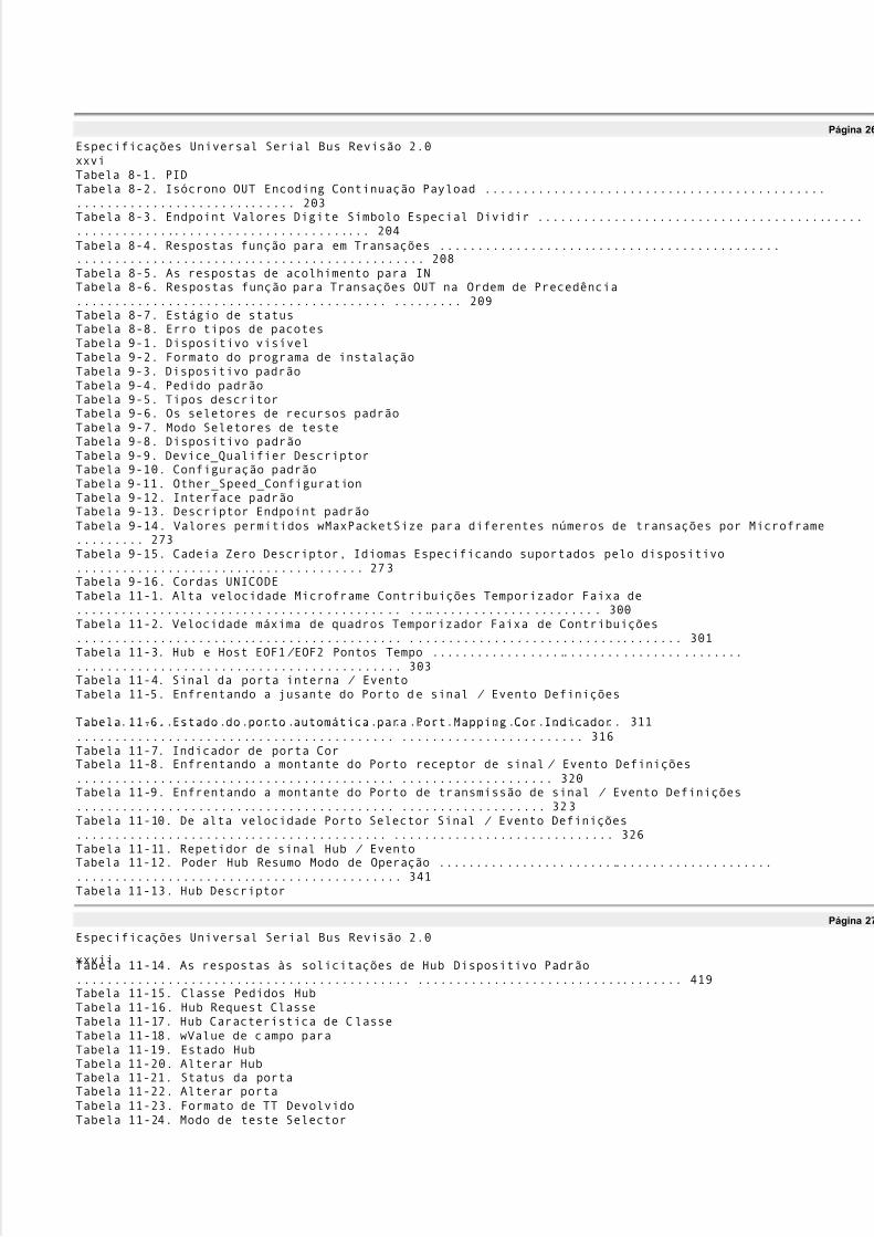
Especificações Universal Serial Bus Revisão 2.0xxviTabela 8-1. PIDTabela 8-2. Isócrono OUT Encoding Continuação Payload .......................................................................... 203Tabela 8-3. Endpoint Valores Digite Símbolo Especial Dividir .................................................................................. 204Tabela 8-4. Respostas função para em Transações ........................................................................................... 208Tabela 8-5. As respostas de acolhimento para INTabela 8-6. Respostas função para Transações OUT na Ordem de Precedência......................................... ......... 209Tabela 8-7. Estágio de statusTabela 8-8. Erro tipos de pacotesTabela 9-1. Dispositivo visívelTabela 9-2. Formato do programa de instalaçãoTabela 9-3. Dispositivo padrãoTabela 9-4. Pedido padrãoTabela 9-5. Tipos descritorTabela 9-6. Os seletores de recursos padrãoTabela 9-7. Modo Seletores de testeTabela 9-8. Dispositivo padrãoTabela 9-9. Device_Qualifier DescriptorTabela 9-10. Configuração padrãoTabela 9-11. Other_Speed_ConfigurationTabela 9-12. Interface padrãoTabela 9-13. Descriptor Endpoint padrãoTabela 9-14. Valores permitidos wMaxPacketSize para diferentes números de transações por Microframe......... 273Tabela 9-15. Cadeia Zero Descriptor, Idiomas Especificando suportados pelo dispositivo...................................... 273Tabela 9-16. Cordas UNICODETabela 11-1. Alta velocidade Microframe Contribuições Temporizador Faixa de........................................... .......................... 300Tabela 11-2. Velocidade máxima de quadros Temporizador Faixa de Contribuições........................................... .................................... 301Tabela 11-3. Hub e Host EOF1/ EOF2 Pontos Tempo ..................................................................................... 303Tabela 11-4. Sinal da porta interna / EventoTabela 11-5. Enfrentando a jusante do Porto de sinal / Evento Definições
........................................... ............................. 311Tabela 11-6. Estado do porto automática para Port Mapping Cor Indicador
.......................................... ........................ 316Tabela 11-7. Indicador de porta CorTabela 11-8. Enfrentando a montante do Porto receptor de sinal / Evento Definições.......................................... .................... 320Tabela 11-9. Enfrentando a montante do Porto de transmissão de sinal / Evento Definições.......................................... ................... 323Tabela 11-10. De alta velocidade Porto Selector Sinal / Evento Definições......................................... ............................. 326Tabela 11-11. Repetidor de sinal Hub / EventoTabela 11-12. Poder Hub Resumo Modo de Operação ........................................................................................ 341Tabela 11-13. Hub Descriptor
Página 27
Especificações Universal Serial Bus Revisão 2.0
xxviiTabela 11-14. As respostas às solicitações de Hub Dispositivo Padrão............................................ ................................... 419Tabela 11-15. Classe Pedidos HubTabela 11-16. Hub Request ClasseTabela 11-17. Hub Característica de ClasseTabela 11-18. wValue de campo paraTabela 11-19. Estado HubTabela 11-20. Alterar HubTabela 11-21. Status da portaTabela 11-22. Alterar portaTabela 11-23. Formato de TT DevolvidoTabela 11-24. Modo de teste Selector

5/8/2018 Versão traduzida de USB Protocolo completo - slidepdf.com
http://slidepdf.com/reader/full/versao-traduzida-de-usb-protocolo-completo 22/112
Tabela 11-25. Porta Indicador Selector
Página 28
Especificações Universal Serial Bus Revisão 2.0xxviii
Página 29
Especificações Universal Serial Bus Revisão 2.0
1Capítulo 1Introdução1.1 MotivaçãoA motivação original para o Universal Serial Bus (USB) vieram de três considerações inter-relacionados:�Conexão do PC para o telefoneÉ bem entendido que a junção da computação e de comunicação serão a base para a próximageração de aplicações de produtividade. O movimento de dados da máquina orientada e humanos orientadatipos de um local ou ambiente para outro depende de conectividade onipresente e barato.Infelizmente, as indústrias de computação e comunicação têm evoluído de forma independente.O USBfornece um link onipresente que pode ser usado em uma ampla gama de PC para telefone interconexões.�Facilidade de usoA falta de flexibilidade na reconfiguração do PC tem sido reconhecida como o calcanhar de Aquiles para asuamaior implantação. A combinação de interfaces amigáveis e gráfica do hardware e
mecanismos de software associado com arquiteturas nova geração de ônibus fizeram computadores menosconfronto e mais fácil de reconfigurar. No entanto, do ponto do usuário final de vista, do PC / Ointerfaces, tais como serial / paralela portas, teclado, mouse / / joystick interfaces, etc, não têm oatributos de plug-and-play.�Expansão portuáriaA adição de periféricos externos continua a ser restringida por uma disponibilidade de porta.A falta deum bi-direcional, de baixo custo, baixa velocidade-média bus periférico tem impedido a proliferação criativa dosperiféricos, como telefone / fax / modem adaptadores, secretárias eletrônicas, scanners, PDAs, teclados,ratos, etc existentes interconexões são otimizados para um ou dois produtos ponto.À medida que cada novafunção oucapacidade é adicionada ao PC, uma nova interface foi definido para atender a essa necessidade.A motivação mais recente para USB 2.0 decorre do fato de que os PCs têm um desempenho cada vez maiore são capazes de processar grandes quantidades de dados. Ao mesmo tempo, periféricos de PC teracrescentado maisdesempenho e funcionalidade. Aplicações do usuário, como a demanda de imagem digital um alto desempenho
conexão entre o PC e estes periféricos cada vez mais sofisticados.USB 2.0 atende a essa necessidadepela adição de uma taxa de transferência terço dos 480 Mb / s para a 12 Mb / s e 1,5 Mb / s originalmentedefinido para USB.USB 2.0 é uma evolução natural da USB, proporcionando o aumento da largura de banda desejada, preservandoamotivações originais para USB e mantendo total compatibilidade com os periféricos já existentes.Assim, USB continua a ser a resposta para a conectividade para a arquitetura PC.É um jejum, bi-direcional,isócrono, de baixo custo, interface acoplável dinamicamente série que é consistente com os requisitos daPlataforma de PC de hoje e de amanhã.1.2 O objectivo da EspecificaçãoEste documento define uma USB padrão da indústria. A especificação descreve os atributos de ônibus, odefinição do protocolo, tipos de transações, gerenciamento de ônibus, ea interface de programaçãonecessária paraprojetar e construir sistemas e periféricos que são compatíveis com esse padrão.O objetivo é permitir que tais dispositivos de diferentes fornecedores para interoperar em uma arquiteturaaberta. O
especificação destina-se como um reforço para a arquitetura PC, abrangendo portátil, desktop negócio, eambientes domésticos. Pretende-se que a especificação permite OEMs e desenvolvedores de sistemasperiféricosespaço adequado para a versatilidade do produto e diferenciação no mercado sem o fardo decarregarobsoletointerfaces ou perder a compatibilidade.
Página 30
Especificações Universal Serial Bus Revisão 2.021.3 Escopo do DocumentoA especificação é dirigido principalmente para desenvolvedores de periféricos e OEMs sistema, mas fornecevaliosas
5/8/2018 Versão traduzida de USB Protocolo completo - slidepdf.com
http://slidepdf.com/reader/full/versao-traduzida-de-usb-protocolo-completo 23/112
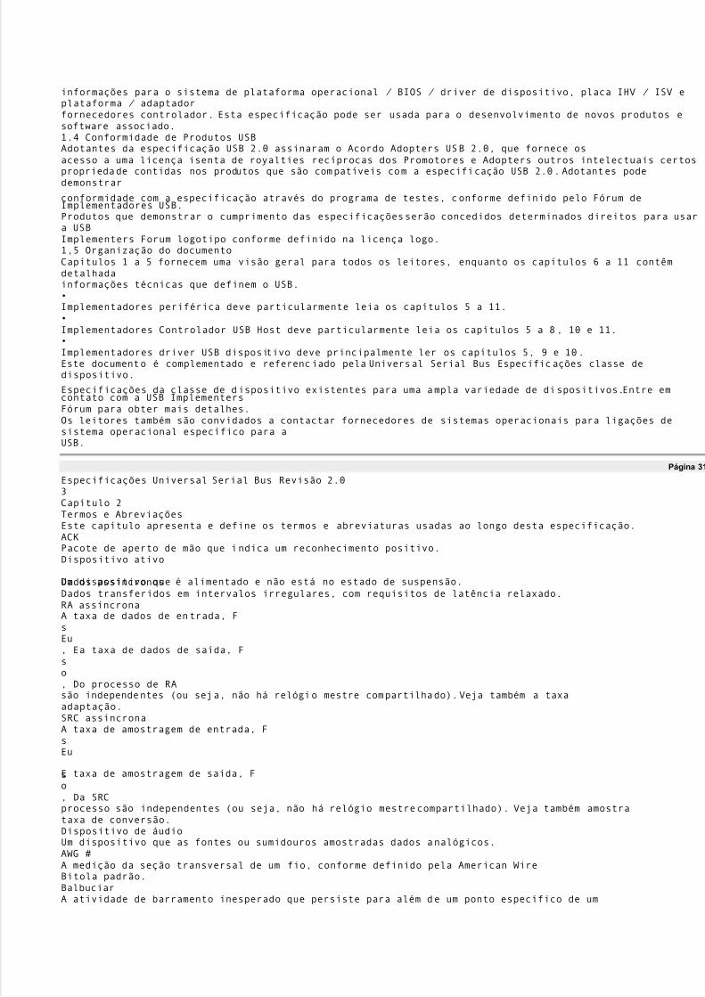
informações para o sistema de plataforma operacional / BIOS / driver de dispositivo, placa IHV / ISV eplataforma / adaptadorfornecedores controlador. Esta especificação pode ser usada para o desenvolvimento de novos produtos esoftware associado.1.4 Conformidade de Produtos USBAdotantes da especificação USB 2.0 assinaram o Acordo Adopters USB 2.0, que fornece osacesso a uma licença isenta de royalties recíprocas dos Promotores e Adopters outros intelectuais certospropriedade contidas nos produtos que são compatíveis com a especificação USB 2.0. Adotantes podedemonstrar
conformidade com a especificação através do programa de testes, conforme definido pelo Fórum deImplementadores USB.Produtos que demonstrar o cumprimento das especificações serão concedidos determinados direitos para usara USBImplementers Forum logotipo conforme definido na licença logo.1,5 Organização do documentoCapítulos 1 a 5 fornecem uma visão geral para todos os leitores, enquanto os capítulos 6 a 11 contêmdetalhadainformações técnicas que definem o USB.�Implementadores periférica deve particularmente leia os capítulos 5 a 11.�Implementadores Controlador USB Host deve particularmente leia os capítulos 5 a 8, 10 e 11.�Implementadores driver USB dispositivo deve principalmente ler os capítulos 5, 9 e 10.Este documento é complementado e referenciado pela Universal Serial Bus Especificações classe dedispositivo.
Especificações da classe de dispositivo existentes para uma ampla variedade de dispositivos.Entre emcontato com a USB ImplementersFórum para obter mais detalhes.Os leitores também são convidados a contactar fornecedores de sistemas operacionais para ligações desistema operacional específico para aUSB.
Página 31
Especificações Universal Serial Bus Revisão 2.03Capítulo 2Termos e AbreviaçõesEste capítulo apresenta e define os termos e abreviaturas usadas ao longo desta especificação.ACKPacote de aperto de mão que indica um reconhecimento positivo.Dispositivo ativo
Um dispositivo que é alimentado e não está no estado de suspensão.Dados assíncronosDados transferidos em intervalos irregulares, com requisitos de latência relaxado.RA assíncronaA taxa de dados de entrada, FsEu, Ea taxa de dados de saída, Fso, Do processo de RAsão independentes (ou seja, não há relógio mestre compartilhado). Veja também a taxaadaptação.SRC assíncronaA taxa de amostragem de entrada, FsEu
E taxa de amostragem de saída, Fso, Da SRCprocesso são independentes (ou seja, não há relógio mestre compartilhado). Veja também amostrataxa de conversão.Dispositivo de áudioUm dispositivo que as fontes ou sumidouros amostradas dados analógicos.AWG #A medição da seção transversal de um fio, conforme definido pela American WireBitola padrão.BalbuciarA atividade de barramento inesperado que persiste para além de um ponto específico de um

5/8/2018 Versão traduzida de USB Protocolo completo - slidepdf.com
http://slidepdf.com/reader/full/versao-traduzida-de-usb-protocolo-completo 24/112
(Micro) frame.Largura de bandaA quantidade de dados transmitidos por unidade de tempo, normalmente de bits por segundo (b / s)ou bytes por segundo (B / s).Big EndianUm método de armazenamento de dados que coloca o byte mais significativo de múltiplos bytesvalores em um endereço menor de armazenamento. Por exemplo, um inteiro de 16 bits armazenados em grandesformato endian coloca o byte menos significativo no endereço mais alto eobyte mais significativo no endereço mais baixo. Veja também little endian.
BitA unidade de informação usada por computadores digitais. Representa a menor partede memória endereçável dentro de um computador. Um pouco expressa a escolha entreduas possibilidades e é normalmente representado por um lógico (1) ou zero (0).Bit StuffingInserção de um "0" bit em um fluxo de dados para fazer uma transição elétrica nafios de dados, permitindo que uma PLL de permanecer bloqueado.b / sTaxa de transmissão expressa em bits por segundo.B / sTaxa de transmissão expressa em bytes por segundo.BufferArmazenamento usado para compensar a diferença nas taxas de dados ou tempo de ocorrênciade eventos, durante a transmissão de dados de um dispositivo para outro.Transferência em blocoUm dos quatro tipos de transferência USB. Transferências em massa não são periódicas, grandesrajadas de comunicação normalmente utilizados para uma transferência que pode usar qualquer disponível
largura de banda e também pode ser adiada até que a largura de banda disponível.Veja tambémtipo de transferência.Enumeração de BUSDetectar e identificar dispositivos USB.
Página 32
Especificações Universal Serial Bus Revisão 2.04ByteUm elemento de dados que é de oito bits de tamanho.CapacidadesOs atributos de um dispositivo USB que são administrados pelo host.CaracterísticasEssas qualidades de um dispositivo USB que são imutáveis, como por exemplo, o dispositivoclasse é uma característica do dispositivo.Cliente
Software residente na máquina que interage com o software do sistema USB paraprovidenciar a transferência de dados entre uma função eo host. O cliente é muitas vezes odados do provedor e consumidor de dados transferidos.Configurando SoftwareResidente de software no host que é responsável por configurar um Dispositivo USB. Este pode ser umsistema configurador ou software específico para o dispositivo.Endpoint controleUm par de terminais do dispositivo com o número de endpoint mesmos que são usadospor umtubo de controle. Terminais de controle de transferência de dados em ambas as direções e, portanto,use ambas as direções ponto final de um endereço de dispositivo e número de endpointcombinação. Assim, cada ponto de controle consome dois endereços de endpoint.Controle de tubulaçãoMesmo que um cano de mensagem.Transfer ControlUm dos quatro tipos de transferência USB. Transfere o controle de apoioconfiguração do comando / / status de comunicação entre o cliente eo tipo defunção. See also transfer type.
CRCSee Cyclic Redundancy Check.CTIComputer Telephony Integration.Redundância CíclicaCheck (CRC)A check performed on data to see if an error has occurred in transmitting,reading, or writing the data. The result of a CRC is typically stored ortransmitted with the checked data. The stored or transmitted result iscompared to a CRC calculated for the data to determine if an error hasocorreu. Quem recebe o CRC o recalcula par aver se foi transferido do forma correta.Default AddQressAn address defined by the USB Specification and used by a USB device when

5/8/2018 Versão traduzida de USB Protocolo completo - slidepdf.com
http://slidepdf.com/reader/full/versao-traduzida-de-usb-protocolo-completo 25/112
it is first powered or reset. The default address is 00H.Tubulação padrãoThe message pipe created by the USB System Software to pass control andstatus information between the host and a USB device's endpoint zero.DispositivoA logical or physical entity that performs a function. The actual entitydescribed depends on the context of the reference. At the lowest level, devicemay refer to a single hardware component, as in a memory device. At a higherlevel, it may refer to a collection of hardware components that perform a
particular function, such as a USB interface device. At an even higher level,device may refer to the function performed by an entity attached to the USB;for example, a data/ FAX modem device. Devices may be physical, electrical,addressable, and logical.When used as a non-specific reference, a USB device is either a hub or afunção.Device AddressA seven-bit value representing the address of a device on the USB. O dispositivoaddress is the default address (00H) when the USB device is first powered orthe device is reset. Devices are assigned a unique device address by the USBSystem Software.
Página 33
Especificações Universal Serial Bus Revisão 2.05Device EndpointA uniquely addressable portion of a USB device that is the source or sink ofinformation in a communication flow between the host and device. Veja tambémendpoint address.Device ResourcesResources provided by USB devices, such as buffer space and endpoints.Veralso Host Resources and Universal Serial Bus Resources.Device SoftwareSoftware that is responsible for using a USB device. This software may ormay not also be responsible for configuring the device for use.Rio abaixoThe direction of data flow from the host or away from the host. A downstreamport is the port on a hub electrically farthest from the host that generatesdownstream data traffic from the hub. Downstream ports receive upstreamdata traffic.MotoristaWhen referring to hardware, an I/ O pad that drives an external load.Quandoreferring to software, a program responsible for interfacing to a hardware
device, that is, a device driver.DWORDDouble word. A data element that is two words (ie, four bytes or 32 bits) intamanho.Dynamic Insertionand RemovalThe ability to attach and remove devices while the host is in operation.E2PROMSee Electrically Erasable Programmable Read Only Memory.EEPROMSee Electrically Erasable Programmable Read Only Memory.EletricamenteErasableProgramávelRead Only Memory
(EEPROM)Non-volatile rewritable memory storage technology.Usuário finalThe user of a host.EndpointSee device endpoint.Endpoint AddressThe combination of an endpoint number and an endpoint direction on a USBdispositivo. Each endpoint address supports data transfer in one direction.Endpoint DirectionThe direction of data transfer on the USB. The direction can be either IN orOUT. IN refers to transfers to the host; OUT refers to transfers from the host.Endpoint Number

5/8/2018 Versão traduzida de USB Protocolo completo - slidepdf.com
http://slidepdf.com/reader/full/versao-traduzida-de-usb-protocolo-completo 26/112
A four-bit value between 0H and FH, inclusive, associated with an endpoint ona USB device.Envelope detectorAn electronic circuit inside a USB device that monitors the USB datalines anddetects certain voltage related signal characteristics.EOFEnd-of-(micro)Frame.EOPEnd-of-Packet.
Porta externaSee port.Eye patternA representation of USB signaling that provides minimum and maximumvoltage levels as well as signal jitter.False EOPA spurious, usually noise-induced event that is interpreted by a packet receiveras an EOP.
Página 34
Especificações Universal Serial Bus Revisão 2.06QuadroA 1 millisecond time base established on full-/ low-speed buses.Frame PatternA sequence of frames that exhibit a repeating pattern in the number of samplestransmitted per frame. For a 44.1 kHz audio transfer, the frame pattern couldbe nine frames containing 44 samples followed by one frame containing45 samples.FsSee sample rate.Full-duplexComputer data transmission occurring in both directions simultaneously.Full-speedUSB operation at 12 Mb/ s. See also low-speed and high-speed.FunçãoA USB device that provides a capability to the host, such as an ISDNconnection, a digital microphone, or speakers.Handshake PacketA packet that acknowledges or rejects a specific condition. For examples, seeACK and NAK.High-bandwidth
endpointA high-speed device endpoint that transfers more than 1024 bytes and less than3073 bytes per microframe.De alta velocidadeUSB operation at 480 Mb/ s. See also low-speed and full-speed.AnfitriãoThe host computer system where the USB Host Controller is installed.Esteincludes the host hardware platform (CPU, bus, etc.) and the operating systemem uso.Host ControllerThe host's USB interface.Host ControllerDriver (HCD)The USB software layer that abstracts the Host Controller hardware.O HostController Driver provides an SPI for interaction with a Host Controller.OHost Controller Driver hides the specifics of the Host Controller hardwareimplementação.
Host ResourcesResources provided by the host, such as buffer space and interrupts.Veja tambémDevice Resources and Universal Serial Bus Resources.CuboA USB device that provides additional connections to the USB.Hub TierOne plus the number of USB links in a communication path between the hostand a function. See Figure 4-1.Interrupt Request(IRQ)A hardware signal that allows a device to request attention from a host.Ohost typically invokes an interrupt service routine to handle the condition thatcaused the request.

5/8/2018 Versão traduzida de USB Protocolo completo - slidepdf.com
http://slidepdf.com/reader/full/versao-traduzida-de-usb-protocolo-completo 27/112
Interrupt TransferOne of the four USB transfer types. Interrupt transfer characteristics are smalldata, non-periodic, low-frequency, and bounded-latency. Interrupt transfersare typically used to handle service needs. See also transfer type.I/ O Request PacketAn identifiable request by a software client to move data between itself (on thehost) and an endpoint of a device in an appropriate direction.IRPSee I/ O Request Packet.
IRQSee Interrupt Request.Isochronous DataA stream of data whose timing is implied by its delivery rate.Isochronous DeviceAn entity with isochronous endpoints, as defined in the USB Specification, thatsources or sinks sampled analog streams or synchronous data streams.
Página 35
Especificações Universal Serial Bus Revisão 2.07Isochronous SinkEndpointAn endpoint that is capable of consuming an isochronous data stream that issent by the host.Isochronous SourceEndpointAn endpoint that is capable of producing an isochronous data stream andsending it to the host.IsócronoTransferênciaOne of the four USB transfer types. Isochronous transfers are used whenworking with isochronous data. Isochronous transfers provide periodic,continuous communication between host and device. See also transfer type.JitterA tendency toward lack of synchronization caused by mechanical or electricalalterações. More specifically, the phase shift of digital pulses over atransmission medium.kb / sTransmission rate expressed in kilobits per second.kB/ sTransmission rate expressed in kilobytes per second.Little Endian
Method of storing data that places the least significant byte of multiple-bytevalues at lower storage addresses. For example, a 16-bit integer stored in littleendian format places the least significant byte at the lower address and themost significant byte at the next address. See also big endian.LOALoss of bus activity characterized by an SOP without a corresponding EOP.Baixa velocidadeUSB operation at 1.5 Mb/ s. See also full-speed and high-speed.LSbLeast significant bit.LSBLeast significant byte.Mb/ sTransmission rate expressed in megabits per second.MB / sTransmission rate expressed in megabytes per second.Message Pipe
A bi-directional pipe that transfers data using a request/ data/ status paradigm.The data has an imposed structure that allows requests to be reliably identifiedand communicated.MicroframeA 125 microsecond time base established on high-speed buses.MSbMost significant bit.MSBMost significant byte.NAKHandshake packet indicating a negative acknowledgment.Non Return to ZeroInvert (NRZI)

5/8/2018 Versão traduzida de USB Protocolo completo - slidepdf.com
http://slidepdf.com/reader/full/versao-traduzida-de-usb-protocolo-completo 28/112
A method of encoding serial data in which ones and zeroes are represented byopposite and alternating high and low voltages where there is no return to zero(reference) voltage between encoded bits. Eliminates the need for clockpulsos.NRZISee Non Return to Zero Invert.ObjetoHost software or data structure representing a USB entity.Pacote
A bundle of data organized in a group for transmission. Packets typicallycontain three elements: control information (eg, source, destination, andlength), the data to be transferred, and error detection and correction bits.Packet BufferThe logical buffer used by a USB device for sending or receiving a singlepacote. This determines the maximum packet size the device can send orreceber.
Página 36
Especificações Universal Serial Bus Revisão 2.08Packet ID (PID)A field in a USB packet that indicates the type of packet, and by inference, theformat of the packet and the type of error detection applied to the packet.FaseA token, data, or handshake packet. A transaction has three phases.Phase Locked Loop(PLL)A circuit that acts as a phase detector to keep an oscillator in phase with anincoming frequency.Physical DeviceA device that has a physical implementation; eg, speakers, microphones, andCD players.PIDSee Packet ID.TuboA logical abstraction representing the association between an endpoint on adevice and software on the host. A pipe has several attributes; for example, apipe may transfer data as streams (stream pipe) or messages (message pipe).See also stream pipe and message pipe.PLLSee Phase Locked Loop.Votação
Asking multiple devices, one at a time, if they have any data to transmit.PORSee Power On Reset.PortoPoint of access to or from a system or circuit. For the USB, the point where aUSB device is attached.Power On Reset(POR)Restoring a storage device, register, or memory to a predetermined state whenpower is applied.ProgramávelTaxa de DadosEither a fixed data rate (single-frequency endpoints), a limited number of datarates (32 kHz, 44.1 kHz, 48 kHz, «), or a continuously programmable datataxa. The exact programming capabilities of an endpoint must be reported inthe appropriate class-specific endpoint descriptors.Protocolo
A specific set of rules, procedures, or conventions relating to format and timingof data transmission between two devices.RASee rate adaptation.Rate AdaptationThe process by which an incoming data stream, sampled at FsEu, is converted toan outgoing data stream, sampled at Fso,with a certain loss of quality,

5/8/2018 Versão traduzida de USB Protocolo completo - slidepdf.com
http://slidepdf.com/reader/full/versao-traduzida-de-usb-protocolo-completo 29/112
determined by the rate adaptation algorithm. Error control mechanisms arerequired for the process. FsEue Fsocan be different and asynchronous. Fs
Euéthe input data rate of the RA; Fsois the output data rate of the RA.PedidoA request made to a USB device contained within the data portion of a SETUPpacote.AposentarThe action of completing service for a transfer and notifying the appropriatesoftware client of the completion.Root HubA USB hub directly attached to the Host Controller. This hub (tier 1) isattached to the host.Porto raizThe downstream port on a Root Hub.
AmostraThe smallest unit of data on which an endpoint operates; a property of anendpoint.Sample Rate (Fs)The number of samples per second, expressed in Hertz (Hz).
Página 37
Especificações Universal Serial Bus Revisão 2.09Taxa de AmostragemConversion (SRC)A dedicated implementation of the RA process for use on sampled analog datariachos. The error control mechanism is replaced by interpolating techniques.Serviço
A procedure provided by a System Programming Interface (SPI).Service IntervalThe period between consecutive requests to a USB endpoint to send or receivede dados.Service JitterThe deviation of service delivery from its scheduled delivery time.Service RateThe number of services to a given endpoint per unit time.SOFSee Start-of-Frame.SOPStart-of-Packet.SPISee System Programming Interface.Split transactionA transaction type supported by host controllers and hubs. This transactiontype allows full- and low-speed devices to be attached to hubs operating at
de alta velocidade.SRCSee Sample Rate Conversion.EtapaOne part of the sequence composing a control transfer; stages include the Setupstage, the Data stage, and the Status stage.Start-de-Frame(SOF)The first transaction in each (micro)frame. An SOF allows endpoints toidentify the start of the (micro)frame and synchronize internal endpoint clocksto the host.Stream PipeA pipe that transfers data as a stream of samples with no defined USB

5/8/2018 Versão traduzida de USB Protocolo completo - slidepdf.com
http://slidepdf.com/reader/full/versao-traduzida-de-usb-protocolo-completo 30/112
estrutura.SincronizaçãoTipoA classification that characterizes an isochronous endpoint's capability toconnect to other isochronous endpoints.Synchronous RAThe incoming data rate, FsEu
, and the outgoing data rate, Fso, of the RA processare derived from the same master clock. There is a fixed relation between FsEue Fso.Synchronous SRCThe incoming sample rate, FsEu, and outgoing sample rate, Fs
o, of the SRCprocess are derived from the same master clock. There is a fixed relationbetween FsEue Fso.SistemaProgramaçãoInterface (SPI)A defined interface to services provided by system software.TDMSee Time Division Multiplexing.TDR
See Time Domain Reflectometer.TerminaçãoPassive components attached at the end of cables to prevent signals from beingreflected or echoed.Time DivisionMultiplexação(TDM)A method of transmitting multiple signals (data, voice, and/ or video)simultaneously over one communications medium by interleaving a piece ofeach signal one after another.Time DomainReflectometer(TDR)An instrument capable of measuring impedance characteristics of the USBsignal lines.
Página 38
Especificações Universal Serial Bus Revisão 2.010TimeoutThe detection of a lack of bus activity for some predetermined interval.Token PacketA type of packet that identifies what transaction is to be performed on the bus.TransaçãoThe delivery of service to an endpoint; consists of a token packet, optional datapacket, and optional handshake packet. Specific packets are allowed/ requiredbased on the transaction type.Transaçãotradutor

5/8/2018 Versão traduzida de USB Protocolo completo - slidepdf.com
http://slidepdf.com/reader/full/versao-traduzida-de-usb-protocolo-completo 31/112
A functional component of a USB hub. The Transaction Translator responds tospecial high-speed transactions and translates them to full/ low-speedtransactions with full/ low-speed devices attached on downstream facing ports.TransferênciaOne or more bus transactions to move information between a software clientand its function.Transfer TypeDetermines the characteristics of the data flow between a software client andsua função. Four standard transfer types are defined: control, interrupt, bulk,
and isochronous.Turn-around TimeThe time a device needs to wait to begin transmitting a packet after a packethas been received to prevent collisions on the USB. This time is based on thelength and propagation delay characteristics of the cable and the location of thetransmitting device in relation to other devices on the USB.Universal SerialBus Driver (USBD)The host resident software entity responsible for providing common services toclients that are manipulating one or more functions on one or more HostControladores.Universal SerialBus ResourcesResources provided by the USB, such as bandwidth and power. Veja tambémDevice Resources and Host Resources.Rio acimaThe direction of data flow towards the host. An upstream port is the port on a
device electrically closest to the host that generates upstream data traffic fromthe hub. Upstream ports receive downstream data traffic.USBDSee Universal Serial Bus Driver.USB-IFUSB Implementers Forum, Inc. is a nonprofit corporation formed to facilitatethe development of USB compliant products and promote the technology.Virtual DeviceA device that is represented by a software interface layer. Um exemplo de umavirtual device is a hard disk with its associated device driver and clientsoftware that makes it able to reproduce an audio .WAV file.PalavraA data element that is two bytes (16 bits) in size.
Página 39
Especificações Universal Serial Bus Revisão 2.0
11Capítulo 3FundoThis chapter presents a brief description of the background of the Universal Serial Bus(USB), includingdesign goals, features of the bus, and existing technologies.3.1 Goals for the Universal Serial BusThe USB is specified to be an industry-standard extension to the PC architecture with a focus on PCperipherals that enable consumer and business applications. The following criteria were applied indefiningthe architecture for the USB:�Ease-of-use for PC peripheral expansion�Low-cost solution that supports transfer rates up to 480 Mb/ s�Full support for real-time data for voice, audio, and video�
Protocol flexibility for mixed-mode isochronous data transfers and asynchronous messaging�Integration in commodity device technology�Comprehension of various PC configurations and form factors�Provision of a standard interface capable of quick diffusion into product�Enabling new classes of devices that augment the PC's capability�Full backward compatibility of USB 2.0 for devices built to previous versions of the specification
Página 40

5/8/2018 Versão traduzida de USB Protocolo completo - slidepdf.com
http://slidepdf.com/reader/full/versao-traduzida-de-usb-protocolo-completo 32/112
Especificações Universal Serial Bus Revisão 2.0123.2 Taxonomy of Application SpaceFigure 3-1 describes a taxonomy for the range of data traffic workloads that can be serviced over a USB.As can be seen, a 480 Mb/ s bus comprehends the high-speed, full-speed, and low-speed data ranges.Typically, high-speed and full-speed data types may be isochronous, while low-speed data comes frominteractive devices. The USB is primarily a PC bus but can be readily applied to other host-centriccomputing devices. The software architecture allows for future extension of the USB by providing supportfor multiple USB Host Controllers.
LOW-SPEED� Interactive Devices� 10 ² 100 kb/ sFULL-SPEED� Phone, Audio,Compressed Video500 kb/ s ² 10 Mb/ sHIGH-SPEED� Video, Storage� 25 ² 400 Mb/ sPERFORMANCEAPLICAÇÕESATRIBUTOSTeclado, MouseEstileteGame PeripheralsVirtual Reality Peripherals
POTSBanda largaÁudioMicrofoneVídeoArmazenamentoDynamic Attach-DetachLowest CostEase-of-UseDynamic Attach-DetachMultiple PeripheralsLower CostEase-of-UseGuaranteed LatencyGuaranteed BandwidthMultiple PeripheralsBaixo Custo
Ease-of-UseLargura de banda altaImagemGuaranteed Latency�Banda largaDynamic Attach-DetachGuaranteed BandwidthMultiple PeripheralsFigura 3-1. Taxonomia Espaço aplicação
Página 41
Especificações Universal Serial Bus Revisão 2.0133.3 Feature ListThe USB Specification provides a selection of attributes that can achieve multiple price/ performance
integration points and can enable functions that allow differentiation at the systemand component level.Features are categorized by the following benefits:Easy to use for end user�Single model for cabling and connectors�Electrical details isolated from end user (eg, bus terminations)�Self-identifying peripherals, automatic mapping of function to driver and configuration�Dynamically attachable and reconfigurable peripheralsWide range of workloads and applications�

5/8/2018 Versão traduzida de USB Protocolo completo - slidepdf.com
http://slidepdf.com/reader/full/versao-traduzida-de-usb-protocolo-completo 33/112
Suitable for device bandwidths ranging from a few kb/ s to several hundred Mb/ s�Supports isochronous as well as asynchronous transfer types over the same set of wires�Supports concurrent operation of many devices (multiple connections)�Supports up to 127 physical devices�Supports transfer of multiple data and message streams between the host and devices
�Allows compound devices (ie, peripherals composed of many functions)�Lower protocol overhead, resulting in high bus utilizationIsochronous bandwidth�Guaranteed bandwidth and low latencies appropriate for telephony, audio, video, etc.Flexibilidade�Supports a wide range of packet sizes, which allows a range of device buffering options�Allows a wide range of device data rates by accommodating packet buffer size and latencies�Flow control for buffer handling is built into the protocolRobustez�Error handling/ fault recovery mechanism is built into the protocol
�Dynamic insertion and removal of devices is identified in user-perceived real-time�Supports identification of faulty devicesSynergy with PC industry�Protocol is simple to implement and integrate�Consistent with the PC plug-and-play architecture�Leverages existing operating system interfaces
Página 42
Especificações Universal Serial Bus Revisão 2.014Low-cost implementation
�Low-cost subchannel at 1.5 Mb/ s�Optimized for integration in peripheral and host hardware�Suitable for development of low-cost peripherals�Low-cost cables and connectors�Uses commodity technologiesUpgrade path�Architecture upgradeable to support multiple USB Host Controllers in a system
Página 43
Especificações Universal Serial Bus Revisão 2.015
Capítulo 4Visão geral sobre arquiteturaThis chapter presents an overview of the Universal Serial Bus (USB) architecture and key concepts.OUSB is a cable bus that supports data exchange between a host computer and a wide range ofsimultaneously accessible peripherals. The attached peripherals share USB bandwidth through a host-scheduled, token-based protocol. The bus allows peripherals to be attached, configured, used, and detachedwhile the host and other peripherals are in operation.Later chapters describe the various components of the USB in greater detail.4.1 USB System DescriptionA USB system is described by three definitional areas:�USB interconnect�

5/8/2018 Versão traduzida de USB Protocolo completo - slidepdf.com
http://slidepdf.com/reader/full/versao-traduzida-de-usb-protocolo-completo 34/112
Dispositivos USB�USB hostThe USB interconnect is the manner in which USB devices are connected to and communicate with thehost. Isto inclui o seguinte:�Bus Topology: Connection model between USB devices and the host.�Inter-layer Relationships: In terms of a capability stack, the USB tasks that are performed at each layer
in the system.�Data Flow Models: The manner in which data moves in the system over the USB between producerse consumidores.�USB Schedule: The USB provides a shared interconnect. Access to the interconnect isscheduled inorder to support isochronous data transfers and to eliminate arbitration overhead.USB devices and the USB host are described in detail in subsequent sections.
Página 44
Universal Serial Specification Revision 2.0164.1.1 Bus TopologyThe USB connects USB devices with the USB host. The USB physical interconnect is a tiered startopologia. A hub is at the center of each star. Each wire segment is a point-to-point connection betweenthehost and a hub or function, or a hub connected to another hub or function. Figure 4-1 illustrates thetopology of the USB.Due to timing constraints allowed for hub and cable propagation times, the maximum number of tiersallowed is seven (including the root tier). Note that in seven tiers, five non-root hubs maximum can besupported in a communication path between the host and any device. A compound device (see Figure 4-1)occupies two tiers; therefore, it cannot be enabled if attached at tier level seven. Only functions can beenabled in tier seven.Host (Tier 1)Nível 2Tier 3Tier 4Tier 5Hub 1Hub 2AnfitriãoRootHubHub 3
Hub 4FuncFuncFuncFuncFuncFuncTier 6Tier 7Hub 5Hub 6Hub 7FuncCompound DeviceFigura 4-1. Topologia Bus4.1.1.1 USB HostThere is only one host in any USB system. The USB interface to the host computer system is referred to as
the Host Controller. The Host Controller may be implemented in a combination of hardware, firmware, orsoftware. A root hub is integrated within the host system to provide one or more attachmentpoints.Additional information concerning the host may be found in Section 4.9 and in Chapter 10.
Página 45
Especificações Universal Serial Bus Revisão 2.0174.1.1.2 USB DevicesUSB devices are one of the following:�Hubs, which provide additional attachment points to the USB�Functions, which provide capabilities to the system, such as an ISDN connection, a digital joystick, or
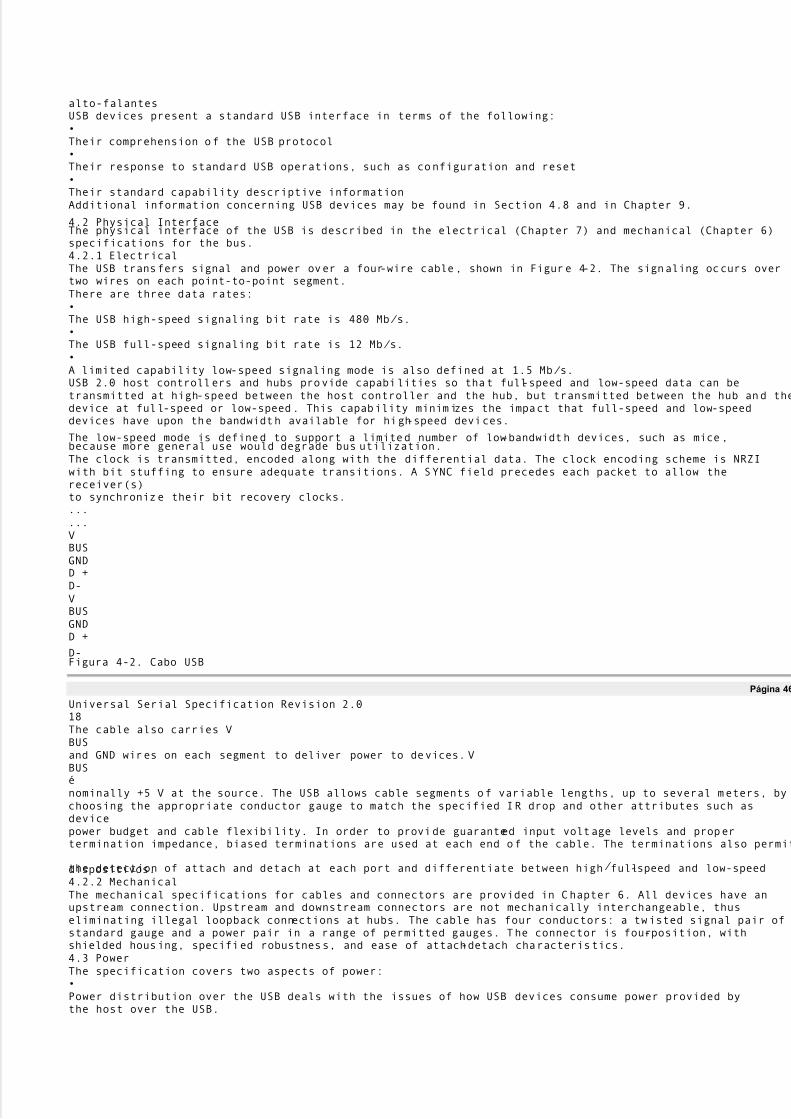
5/8/2018 Versão traduzida de USB Protocolo completo - slidepdf.com
http://slidepdf.com/reader/full/versao-traduzida-de-usb-protocolo-completo 35/112
alto-falantesUSB devices present a standard USB interface in terms of the following:�Their comprehension of the USB protocol�Their response to standard USB operations, such as configuration and reset�Their standard capability descriptive informationAdditional information concerning USB devices may be found in Section 4.8 and in Chapter 9.
4.2 Physical InterfaceThe physical interface of the USB is described in the electrical (Chapter 7) and mechanical (Chapter 6)specifications for the bus.4.2.1 ElectricalThe USB transfers signal and power over a four-wire cable, shown in Figure 4-2. The signaling occurs overtwo wires on each point-to-point segment.There are three data rates:�The USB high-speed signaling bit rate is 480 Mb/ s.�The USB full-speed signaling bit rate is 12 Mb/ s.�A limited capability low-speed signaling mode is also defined at 1.5 Mb/ s.USB 2.0 host controllers and hubs provide capabilities so that full-speed and low-speed data can betransmitted at high-speed between the host controller and the hub, but transmitted between the hub and thedevice at full-speed or low-speed. This capability minimizes the impact that full-speed and low-speeddevices have upon the bandwidth available for high-speed devices.
The low-speed mode is defined to support a limited number of low-bandwidth devices, such as mice,because more general use would degrade bus utilization.The clock is transmitted, encoded along with the differential data. The clock encoding scheme is NRZIwith bit stuffing to ensure adequate transitions. A SYNC field precedes each packet to allow thereceiver(s)to synchronize their bit recovery clocks.......VBUSGNDD +D-VBUSGNDD +
D-Figura 4-2. Cabo USB
Página 46
Universal Serial Specification Revision 2.018The cable also carries VBUSand GND wires on each segment to deliver power to devices. VBUSénominally +5 V at the source. The USB allows cable segments of variable lengths, up to several meters, bychoosing the appropriate conductor gauge to match the specified IR drop and other attributes such asdevicepower budget and cable flexibility. In order to provide guaranteed input voltage levels and propertermination impedance, biased terminations are used at each end of the cable. The terminations also permit
the detection of attach and detach at each port and differentiate between high/ full-speed and low-speeddispositivos.4.2.2 MechanicalThe mechanical specifications for cables and connectors are provided in Chapter 6. All devices have anupstream connection. Upstream and downstream connectors are not mechanically interchangeable, thuseliminating illegal loopback connections at hubs. The cable has four conductors: a twisted signal pair ofstandard gauge and a power pair in a range of permitted gauges. The connector is four-position, withshielded housing, specified robustness, and ease of attach-detach characteristics.4.3 PowerThe specification covers two aspects of power:�Power distribution over the USB deals with the issues of how USB devices consume power provided bythe host over the USB.
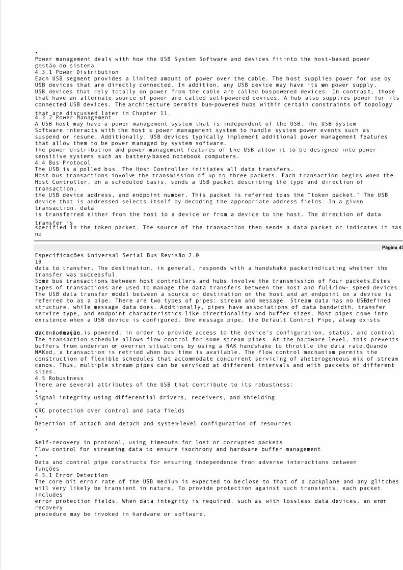
5/8/2018 Versão traduzida de USB Protocolo completo - slidepdf.com
http://slidepdf.com/reader/full/versao-traduzida-de-usb-protocolo-completo 36/112
�Power management deals with how the USB System Software and devices fitinto the host-based powergestão do sistema.4.3.1 Power DistributionEach USB segment provides a limited amount of power over the cable. The host supplies power for use byUSB devices that are directly connected. In addition, any USB device may have its own power supply.USB devices that rely totally on power from the cable are called bus-powered devices. In contrast, thosethat have an alternate source of power are called self-powered devices. A hub also supplies power for itsconnected USB devices. The architecture permits bus-powered hubs within certain constraints of topology
that are discussed later in Chapter 11.4.3.2 Power ManagementA USB host may have a power management system that is independent of the USB. The USB SystemSoftware interacts with the host's power management system to handle system power events such assuspend or resume. Additionally, USB devices typically implement additional power management featuresthat allow them to be power managed by system software.The power distribution and power management features of the USB allow it to be designed into power-sensitive systems such as battery-based notebook computers.4.4 Bus ProtocolThe USB is a polled bus. The Host Controller initiates all data transfers.Most bus transactions involve the transmission of up to three packets. Each transaction begins when theHost Controller, on a scheduled basis, sends a USB packet describing the type and direction oftransaction,the USB device address, and endpoint number. This packet is referred toas the ´token packet.µ The USBdevice that is addressed selects itself by decoding the appropriate address fields. In a giventransaction, datais transferred either from the host to a device or from a device to the host. The direction of data
transfer isspecified in the token packet. The source of the transaction then sends a data packet or indicates it hasno
Página 47
Especificações Universal Serial Bus Revisão 2.019data to transfer. The destination, in general, responds with a handshake packetindicating whether thetransfer was successful.Some bus transactions between host controllers and hubs involve the transmission of four packets.Estestypes of transactions are used to manage the data transfers between the host and full-/ low- speed devices.The USB data transfer model between a source or destination on the host and an endpoint on a device isreferred to as a pipe. There are two types of pipes: stream and message. Stream data has no USB-definedstructure, while message data does. Additionally, pipes have associations of data bandwidth, transferservice type, and endpoint characteristics like directionality and buffer sizes. Most pipes come intoexistence when a USB device is configured. One message pipe, the Default Control Pipe, always exists
once a device is powered, in order to provide access to the device's configuration, status, and controlda informação.The transaction schedule allows flow control for some stream pipes. At the hardware level, this preventsbuffers from underrun or overrun situations by using a NAK handshake to throttle the data rate.QuandoNAKed, a transaction is retried when bus time is available. The flow control mechanism permits theconstruction of flexible schedules that accommodate concurrent servicing of aheterogeneous mix of streamcanos. Thus, multiple stream pipes can be serviced at different intervals and with packets of differentsizes.4.5 RobustnessThere are several attributes of the USB that contribute to its robustness:�Signal integrity using differential drivers, receivers, and shielding�CRC protection over control and data fields�Detection of attach and detach and system-level configuration of resources�
Self-recovery in protocol, using timeouts for lost or corrupted packets�Flow control for streaming data to ensure isochrony and hardware buffer management�Data and control pipe constructs for ensuring independence from adverse interactions betweenfunções4.5.1 Error DetectionThe core bit error rate of the USB medium is expected to be close to that of a backplane and any glitcheswill very likely be transient in nature. To provide protection against such transients, each packetincludeserror protection fields. When data integrity is required, such as with lossless data devices, an errorrecoveryprocedure may be invoked in hardware or software.

5/8/2018 Versão traduzida de USB Protocolo completo - slidepdf.com
http://slidepdf.com/reader/full/versao-traduzida-de-usb-protocolo-completo 37/112
The protocol includes separate CRCs for control and data fields of each packet. A failed CRC is consideredto indicate a corrupted packet. The CRC gives 100% coverage on single- and double-bit errors.4.5.2 Error HandlingThe protocol allows for error handling in hardware or software. Hardware error handling includes reportingand retry of failed transfers. A USB Host Controller will try a transmission that encounters errors up tothree times before informing the client software of the failure. The client software can recover in animplementation-specific way.4.6 System ConfigurationThe USB supports USB devices attaching to and detaching from the USB at any time.Conseqüentemente,
system software must accommodate dynamic changes in the physical bus topology.
Página 48
Universal Serial Specification Revision 2.0204.6.1 Attachment of USB DevicesAll USB devices attach to the USB through ports on specialized USB devices known as hubs. Hubshavestatus bits that are used to report the attachment or removal of a USB device on one of its ports.Oanfitriãoqueries the hub to retrieve these bits. In the case of an attachment, the host enables the port andaddressesthe USB device through the device's control pipe at the default address.The host assigns a unique USB address to the device and then determines if the newly attached USB deviceis a hub or a function. The host establishes its end of the control pipe for the USB device using theassignedUSB address and endpoint number zero.If the attached USB device is a hub and USB devices are attached to its ports, then the above procedure isfollowed for each of the attached USB devices.If the attached USB device is a function, then attachment notifications will be handled by host softwarethatis appropriate for the function.4.6.2 Removal of USB DevicesWhen a USB device has been removed from one of a hub's ports, the hub disables the port and provides anindication of device removal to the host. The removal indication is then handled by appropriate USBSystem Software. If the removed USB device is a hub, the USB System Software must handle the removalof both the hub and of all of the USB devices that were previously attached to the system through the hub.4.6.3 Bus EnumerationBus enumeration is the activity that identifies and assigns unique addresses to devices attached to a busBecause the USB allows USB devices to attach to or detach from the USB at any time, bus enumeration isan on-going activity for the USB System Software. Additionally, bus enumeration for the USB alsoincludes the detection and processing of removals.4.7 Data Flow TypesThe USB supports functional data and control exchange between the USB host and a USB device as a set of
either uni-directional or bi-directional pipes. USB data transfers take place between host software and aparticular endpoint on a USB device. Such associations between the host software and a USB deviceendpoint are called pipes. In general, data movement though one pipe is independent from the data flow inany other pipe. A given USB device may have many pipes. As an example, a given USB device could havean endpoint that supports a pipe for transporting data to the USB device and another endpoint thatsupports apipe for transporting data from the USB device.The USB architecture comprehends four basic types of data transfers:�Control Transfers: Used to configure a device at attach time and can be used for other device-specificpurposes, including control of other pipes on the device.�Bulk Data Transfers: Generated or consumed in relatively large and bursty quantities and have widedynamic latitude in transmission constraints.�Interrupt Data Transfers: Used for timely but reliable delivery of data, for example, characters orcoordinates with human-perceptible echo or feedback response characteristics.
�Isochronous Data Transfers: Occupy a prenegotiated amount of USB bandwidth with a prenegotiateddelivery latency. (Also called streaming real time transfers).A pipe supports only one of the types of transfers described above for any given device configuration.OUSB data flow model is described in more detail in Chapter 5.
Página 49
Especificações Universal Serial Bus Revisão 2.0214.7.1 Control TransfersControl data is used by the USB System Software to configure devices when they are first attached.Outrosdriver software can choose to use control transfers in implementation-specific ways. Data delivery islossless.

5/8/2018 Versão traduzida de USB Protocolo completo - slidepdf.com
http://slidepdf.com/reader/full/versao-traduzida-de-usb-protocolo-completo 38/112
4.7.2 Bulk TransfersBulk data typically consists of larger amounts of data, such as that used for printers or scanners. Bulkdatais sequential. Reliable exchange of data is ensured at the hardware level by using error detection inhardware and invoking a limited number of retries in hardware. Also, the bandwidth taken up by bulk datacan vary, depending on other bus activities.4.7.3 Interrupt TransfersA limited-latency transfer to or from a device is referred to as interrupt data. Such data may bepresented
for transfer by a device at any time and is delivered by the USB at a rate no slower than is specified bythedispositivo.Interrupt data typically consists of event notification, characters, or coordinates that are organized asone ormore bytes. An example of interrupt data is the coordinates from a pointing device. Although an explicittiming rate is not required, interactive data may have response time bounds that the USB must support.4.7.4 Isochronous TransfersIsochronous data is continuous and real-time in creation, delivery, and consumption. Timing-relatedinformation is implied by the steady rate at which isochronous data is received and transferred.Isócronodata must be delivered at the rate received to maintain its timing. In addition to delivery rate,isochronousdata may also be sensitive to delivery delays. For isochronous pipes, the bandwidth required is typicallybased upon the sampling characteristics of the associated function. The latency required is related to thebuffering available at each endpoint.A typical example of isochronous data is voice. If the delivery rate of these data streams is notmaintained,
drop-outs in the data stream will occur due to buffer or frame underruns or overruns. Even if data isdelivered at the appropriate rate by USB hardware, delivery delays introduced by software may degradeapplications requiring real-time turn-around, such as telephony-based audio conferencing.The timely delivery of isochronous data is ensured at the expense of potential transient losses in thedatastream. In other words, any error in electrical transmission is not corrected by hardware mechanisms suchas retries. In practice, the core bit error rate of the USB is expected to be small enough not to be anissue.USB isochronous data streams are allocated a dedicated portion of USB bandwidth to ensure that data canbe delivered at the desired rate. The USB is also designed for minimal delay of isochronous datatransfers.4.7.5 Allocating USB BandwidthUSB bandwidth is allocated among pipes. The USB allocates bandwidth for some pipes when a pipe isestabelecida. USB devices are required to provide some buffering of data. It is assumed that USB devicesrequiring more bandwidth are capable of providing larger buffers. The goal for the USB architectureis toensure that buffering-induced hardware delay is bounded to within a few milliseconds.The USB's bandwidth capacity can be allocated among many different data streams. This allows a wide
range of devices to be attached to the USB. Further, different device bit rates, with a wide dynamicrange,can be concurrently supported.The USB Specification defines the rules for how each transfer type is allowed access to the bus.
Página 50
Universal Serial Specification Revision 2.0224.8 USB DevicesUSB devices are divided into device classes such as hub, human interface, printer, imaging, or massstoragedispositivo. The hub device class indicates a specially designated USB device that provides additional USBattachment points (refer to Chapter 11). USB devices are required to carry information for self-identification and generic configuration. They are also required at all times to display behaviorconsistentwith defined USB device states.
4.8.1 Device CharacterizationsAll USB devices are accessed by a USB address that is assigned when the device is attached andenumeradas. Each USB device additionally supports one or more pipes through which the host maycommunicate with the device. All USB devices must support a specially designated pipe at endpointzero towhich the USB device's USB control pipe will be attached. All USB devices support a common accessmechanism for accessing information through this control pipe.Associated with the control pipe at endpoint zero is the information required tocompletely describe theDispositivo USB. This information falls into the following categories:�Standard: This is information whose definition is common to all USB devices and includes items suchas vendor identification, device class, and power management capability. Device, configuration,interface, and endpoint descriptions carry configuration-related information about the device. Detalhadoinformation about these descriptors can be found in Chapter 9.

5/8/2018 Versão traduzida de USB Protocolo completo - slidepdf.com
http://slidepdf.com/reader/full/versao-traduzida-de-usb-protocolo-completo 39/112
�Class: The definition of this information varies, depending on the device class of the USB device.�USB Vendor: The vendor of the USB device is free to put any information desired here. The format,however, is not determined by this specification.Additionally, each USB device carries USB control and status information.4.8.2 Device DescriptionsTwo major divisions of device classes exist: hubs and functions. Only hubs have the ability to provideadditional USB attachment points. Functions provide additional capabilities to the host.
4.8.2.1 HubsHubs are a key element in the plug-and-play architecture of the USB. Figure 4-3 shows a typical hub. Hubsserve to simplify USB connectivity from the user's perspective and provide robustness at relatively lowcostand complexity.Hubs are wiring concentrators and enable the multiple attachment characteristics of the USB. Ligaçãopoints are referred to as ports. Each hub converts a single attachment point into multiple attachmentpoints.The architecture supports concatenation of multiple hubs.The upstream port of a hub connects the hub towards the host. Each of the downstream ports of a huballows connection to another hub or function. Hubs can detect attach and detach at each downstream portand enable the distribution of power to downstream devices. Each downstream port can be individuallyenabled and attached to either high-, full- or low-speed devices.A USB 2.0 hub consists of three portions: the Hub Controller, the Hub Repeater, and the TransactionTranslator. The Hub Repeater is a protocol-controlled switch between the upstream port and downstreamportos. It also has hardware support for reset and suspend/ resume signaling. The Host Controller providesthe communication to/ from the host. Hub-specific status and control commands permit the host to
configure a hub and to monitor and control its ports. The Transaction Translator provides the mechanismsthat support full-/ low-speed devices behind the hub, while transmitting all device data between the hostandthe hub at high-speed.
Página 51
Especificações Universal Serial Bus Revisão 2.023HUBRio acimaPortoPorto# 1Porto# 7Porto
# 6Porto# 5Porto# 4Porto# 2Porto# 3Figura 4-3. A Typical HubFigure 4-4 illustrates how hubs provide connectivity in a typical desktop computerenvironment.USBHost/ HubMonitorCanetaMouseKBD
TelefonePCHub/ FunctionHub/ FunctionMicTYPICAL USB ARCHITECTURALCONFIGURATIONCuboAlto-falanteFunçãoFunçãoFunçãoFunção

5/8/2018 Versão traduzida de USB Protocolo completo - slidepdf.com
http://slidepdf.com/reader/full/versao-traduzida-de-usb-protocolo-completo 40/112
FunçãoCuboFigura 4-4. Hubs in a Desktop Computer Environment
Página 52
Universal Serial Specification Revision 2.0244.8.2.2 FunctionsA function is a USB device that is able to transmit or receive data or control information over the bus.Afunction is typically implemented as a separate peripheral device with a cable thatplugs into a port on ahub. However, a physical package may implement multiple functions and an embedded hub with a singleCabo USB. This is known as a compound device. A compound device appears to the host as a hub withone or more non-removable USB devices.Each function contains configuration information that describes its capabilities and resourcerequirements.Before a function can be used, it must be configured by the host. This configuration includes allocatingUSB bandwidth and selecting function-specific configuration options.Examples of functions include the following:�A human interface device such as a mouse, keyboard, tablet, or game controller�An imaging device such as a scanner, printer, or camera�A mass storage device such as a CD-ROM drive, floppy drive, or DVD drive4.9 USB Host: Hardware and SoftwareThe USB host interacts with USB devices through the Host Controller. The host is responsible for theseguinte:�Detecting the attachment and removal of USB devices�Managing control flow between the host and USB devices�Managing data flow between the host and USB devices�Collecting status and activity statistics�Providing power to attached USB devicesThe USB System Software on the host manages interactions between USB devicesand host-based devicesoftware. There are five areas of interactions between the USB System Software and device software:�Device enumeration and configuration�
Isochronous data transfers�Asynchronous data transfers�Gerenciamento de energia�Device and bus management information4.10 Architectural ExtensionsThe USB architecture comprehends extensibility at the interface between the Host Controller Driver andUSB Driver. Implementations with multiple Host Controllers, and associated Host ControllerDrivers, arepossível.
Página 53
Especificações Universal Serial Bus Revisão 2.025Capítulo 5USB Data Flow Model
This chapter presents information about how data is moved across the USB.As informações contidas nestecapítuloaffects all implementers. The information presented is at a level above the signaling and protocoldefinitions of the system. Consult Chapter 7 and Chapter 8 for more details about their respective partsofo sistema USB. This chapter provides framework information that is further expanded in Chapters 9through 11. All implementers should read this chapter so they understand the key concepts of the USB.5.1 Implementer ViewpointsThe USB provides communication services between a host and attached USB devices. However, the simpleview an end user sees of attaching one or more USB devices to a host, as in Figure 5-1, is in fact alittlemore complicated to implement than is indicated by the figure. Different views of the system are requiredto explain specific USB requirements from the perspective of different implementers. Several important

5/8/2018 Versão traduzida de USB Protocolo completo - slidepdf.com
http://slidepdf.com/reader/full/versao-traduzida-de-usb-protocolo-completo 41/112
concepts and features must be supported to provide the end user with the reliable operation demanded fromtoday's personal computers. The USB is presented in a layered fashion to ease explanation and allowimplementers of particular USB products to focus on the details related to their product.Host USBDispositivo USBFigura 5-1. Ver simples USB Host / DeviceFigure 5-2 shows a deeper overview of the USB, identifying the different layers of thesystem that will bedescribed in more detail in the remainder of the specification. In particular, there are four focusimplementation areas:
�USB Physical Device: A piece of hardware on the end of a USB cable that performs some useful enduser function.�Client Software: Software that executes on the host, corresponding to a USB device.Este clientesoftware is typically supplied with the operating system or provided along with the USB device.�USB System Software: Software that supports the USB in a particular operating system. O USBSystem Software is typically supplied with the operating system, independently of particular USBdevices or client software.�USB Host Controller (Host Side Bus Interface): The hardware and software that allows USB devicesto be attached to a host.There are shared rights and responsibilities between the four USB system components. The remainder ofthis specification describes the details required to support robust, reliable communication flows betweenafunction and its client.
Página 54
Especificações Universal Serial Bus Revisão 2.026Client SWHost USBControladorUSB LogicalDispositivoFunçãoAnfitriãoPhysical DeviceInterconnectUSB BusInterfaceUSB System
SWActual communications flowLogical communications flowImplementation Focus AreaFunction LayerDispositivo USBCamadaUSB BusInterface LayerFigura 5-2. USB Implementation AreasAs shown in Figure 5-2, the simple connection of a host to a device requires interaction between a numberof layers and entities. The USB Bus Interface layer provides physical/ signaling/ packet connectivitybetween the host and a device. The USB Device layer is the view the USB System Software has forperforming generic USB operations with a device. The Function layer provides additional capabilities tothe host via an appropriate matched client software layer. The USB Device and Function layers each have aview of logical communication within their layer that actually uses the USB Bus Interface layer toaccomplish data transfer.
The physical view of USB communication as described in Chapters 6, 7, and 8 is related to the logicalcommunication view presented in Chapters 9 and 10. This chapter describes those key concepts that affectUSB implementers and should be read by all before proceeding to the remainder of the specification to findthose details most relevant to their product.To describe and manage USB communication, the following concepts are important:�Bus Topology: Section 5.2 presents the primary physical and logical components of the USB and howthey interrelate.�Communication Flow Models: Sections 5.3 through 5.8 describe how communication flows betweenthe host and devices through the USB and defines the four USB transfer types.�Bus Access Management: Section 5.11 describes how bus access is managed within the host to support

5/8/2018 Versão traduzida de USB Protocolo completo - slidepdf.com
http://slidepdf.com/reader/full/versao-traduzida-de-usb-protocolo-completo 42/112
a broad range of communication flows by USB devices.�Special Consideration for Isochronous Transfers: Section 5.12 presents features of the USB specific todevices requiring isochronous data transfers. Device implementers for non-isochronous devices do notneed to read Section 5.12.
Página 55
Especificações Universal Serial Bus Revisão 2.0275.2 Bus TopologyThere are four main parts to USB topology:�Host and Devices: The primary components of a USB system�Physical Topology: How USB elements are connected�Logical Topology: The roles and responsibilities of the various USB elements and how the USBappears from the perspective of the host and a device�Client Software-to-function Relationships: How client software and its related function interfaces on aUSB device view each other5.2.1 USB HostThe host's logical composition is shown in Figure 5-3 and includes the following:�USB Host Controller�Aggregate USB System Software (USB Driver, Host Controller Driver, and host software)�ClienteClient SWHost USBControladorAnfitriãoUSB System SWActual communications flowLogical communications flowFigura 5-3. Host CompositionThe USB host occupies a unique position as the coordinating entity for the USB. In addition to its specialphysical position, the host has specific responsibilities with regard to the USB and its attacheddevices. Ohost controls all access to the USB. A USB device gains access to the bus only by beinggranted access bythe host. The host is also responsible for monitoring the topology of the USB.
For a complete discussion of the host and its duties, refer to Chapter 10.Página 56
Especificações Universal Serial Bus Revisão 2.0285.2.2 USB DevicesA USB physical device's logical composition is shown in Figure 5-4 and includes the following:�USB bus interface�USB logical device�FunçãoUSB physical devices provide additional functionality to the host. The types of functionality provided byUSB devices vary widely. However, all USB logical devices present the same basic interface to the host.This allows the host to manage the USB-relevant aspects of different USB devices in the same manner.To assist the host in identifying and configuring USB devices, each device carries and reports
configuration-informações relacionadas. Some of the information reported is common among all logical devices.Outrosinformation is specific to the functionality provided by the device. The detailed format of thisinformationvaries, depending on the device class of the device.For a complete discussion of USB devices, refer to Chapter 9.USB LogicalDispositivoFunçãoPhysical DeviceUSB BusInterfaceActual communications flow

5/8/2018 Versão traduzida de USB Protocolo completo - slidepdf.com
http://slidepdf.com/reader/full/versao-traduzida-de-usb-protocolo-completo 43/112
Logical communications flowFigura 5-4. Composição dispositivo físico
Página 57
Especificações Universal Serial Bus Revisão 2.0295.2.3 Physical Bus TopologyDevices on the USB are physically connected to the host via a tiered star topology, as illustrated inFigura 5-5. USB attachment points are provided by a special class of USB device known as a hub.Oadditional attachment points provided by a hub are called ports. A host includes an embedded hub calledthe root hub. The host provides one or more attachment points via the root hub. USB devices that provideadditional functionality to the host are known as functions. To prevent circular attachments, a tieredordering is imposed on the star topology of the USB. This results in the tree-like configurationillustrated inFigura 5-5.Root HubCuboCuboDispositivoCompound DeviceAnfitriãoDispositivoDispositivoDispositivoDispositivoDispositivoDispositivoFigura 5-5. USB Physical Bus TopologyMultiple functions may be packaged together in what appears to be a single physical device.Por exemplo,umkeyboard and a trackball might be combined in a single package. Inside the package, the individualfunctions are permanently attached to a hub and it is the internal hub that is connected to theUSB. Quandomultiple functions are combined with a hub in a single package, they are referred to as a compound device.The hub and each function attached to the hub within the compound device is assigned its own deviceendereço. A device that has multiple interfaces controlled independently of each other is referred to as acomposite device. A composite device has only a single device address. From the host's perspective, acompound device is the same as a separate hub with multiple functions attached.Figure 5-5 alsoillustratesa compound device.
Página 58
Especificações Universal Serial Bus Revisão 2.030FS/ LSDispositivoHS HubUSB 1.1 HubFS/ LSDispositivoHS DeviceFull/ Low SpeedHigh Speed Only(2 x 12 Mb/ sCapacity)USB 2.0 HostControladorFigura 5-6. Multiple Full-speed Buses in a High-speed SystemThe hub plays a special role in a high-speed system. The hub isolates the full-/ low-speed signaling
environment from the high-speed signaling environment. Figure 5-6 shows a hub operating in high speedsupporting a high-speed attached device. The hub also allows USB1.1 hubs to attach and operate at full-/ low-speed along with other full-/ low-speed only devices. The host controller also directly supportsattaching full-/ low-speed only devices. Chapter 11 describes the details of how the hubaccomplishes theisolation of the two signaling environments.Each high-speed operating hub essentially adds one (or more) additional full-/ low-speed buses; ie, eachhub supports additional (optionally multiple) 12 Mb/ s of USB full-/ low-speed bandwidth. This allows morefull-/ low-speed buses to be attached without requiring additional host controllers in a system.Apesar dethere can be several 12 Mb/ s full-/ low-speed buses, there are only at most 127 USB devices attached to anysingle host controller.5.2.4 Logical Bus TopologyWhile devices physically attach to the USB in a tiered, star topology, the host communicates with each
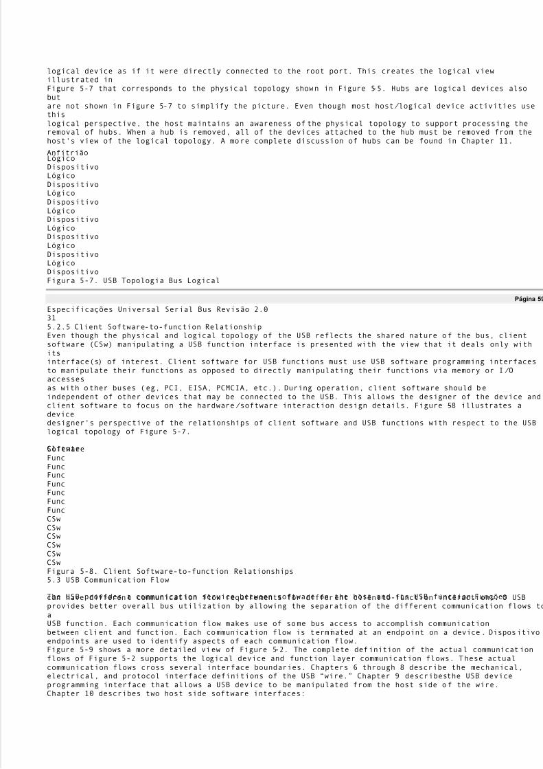
5/8/2018 Versão traduzida de USB Protocolo completo - slidepdf.com
http://slidepdf.com/reader/full/versao-traduzida-de-usb-protocolo-completo 44/112
logical device as if it were directly connected to the root port. This creates the logical viewillustrated inFigure 5-7 that corresponds to the physical topology shown in Figure 5-5. Hubs are logical devices alsobutare not shown in Figure 5-7 to simplify the picture. Even though most host/ logical device activities usethislogical perspective, the host maintains an awareness of the physical topology to support processing theremoval of hubs. When a hub is removed, all of the devices attached to the hub must be removed from thehost's view of the logical topology. A more complete discussion of hubs can be found in Chapter 11.
AnfitriãoLógicoDispositivoLógicoDispositivoLógicoDispositivoLógicoDispositivoLógicoDispositivoLógicoDispositivoLógicoDispositivoFigura 5-7. USB Topologia Bus Logical
Página 59
Especificações Universal Serial Bus Revisão 2.0315.2.5 Client Software-to-function RelationshipEven though the physical and logical topology of the USB reflects the shared nature of the bus, clientsoftware (CSw) manipulating a USB function interface is presented with the view that it deals only withitsinterface(s) of interest. Client software for USB functions must use USB software programming interfacesto manipulate their functions as opposed to directly manipulating their functions via memory or I/ Oaccessesas with other buses (eg, PCI, EISA, PCMCIA, etc.). During operation, client software should beindependent of other devices that may be connected to the USB. This allows the designer of the device andclient software to focus on the hardware/ software interaction design details. Figure 5-8 illustrates adevicedesigner's perspective of the relationships of client software and USB functions with respect to the USBlogical topology of Figure 5-7.
ClienteSoftwareFuncFuncFuncFuncFuncFuncFuncCSwCSwCSwCSwCSwCSwFigura 5-8. Client Software-to-function Relationships5.3 USB Communication Flow
The USB provides a communication service between software on the host and its USB function.Funçõescan have different communication flow requirements for different client-to-function interactions. O USBprovides better overall bus utilization by allowing the separation of the different communication flows toaUSB function. Each communication flow makes use of some bus access to accomplish communicationbetween client and function. Each communication flow is terminated at an endpoint on a device. Dispositivoendpoints are used to identify aspects of each communication flow.Figure 5-9 shows a more detailed view of Figure 5-2. The complete definition of the actual communicationflows of Figure 5-2 supports the logical device and function layer communication flows. These actualcommunication flows cross several interface boundaries. Chapters 6 through 8 describe the mechanical,electrical, and protocol interface definitions of the USB ´wire.µ Chapter 9 describesthe USB deviceprogramming interface that allows a USB device to be manipulated from the host side of the wire.Chapter 10 describes two host side software interfaces:

5/8/2018 Versão traduzida de USB Protocolo completo - slidepdf.com
http://slidepdf.com/reader/full/versao-traduzida-de-usb-protocolo-completo 45/112
�Host Controller Driver (HCD): The software interface between the USB Host Controller and USBSystem Software. This interface allows a range of Host Controller implementations without requiringall host software to be dependent on any particular implementation. One USB Driver can supportdifferent Host Controllers without requiring specific knowledge of a Host Controller implementation.A Host Controller implementer provides an HCD implementation that supports the Host Controller.�USB Driver (USBD): The interface between the USB System Software and the client software.Esteinterface provides clients with convenient functions for manipulating USB devices.
Página 60
Especificações Universal Serial Bus Revisão 2.032SIESIEAnfitriãoControladorUSB BusInterfaceUSB BusInterfaceUSB System SWmanages devicesUSB LogicalDispositivouma coleção deendpointsInterconnectPhysical DeviceAnfitriãoUSB WireBuffersTransferênciasTransaçõesData PerEndpointInterface-específicoFunçãouma coleção deinterfaces deTubulação padrão
to Endpoint ZeroPipe Bundleto an interfacePipe: represents connection abstractionbetween two horizontal entitiesData transport mechanismUSB-relevant format of transported dataNo USBFormatoUSBEmolduradoDadosUSB FramedDadosUSBEmolduradoDados
No USBFormatoInterface xEndpointZeroClient SWmanages an interfaceMechanical,Electrical,Protocolo(Chapter 6, 7, 8)Dispositivo USB(Chapter 9)

5/8/2018 Versão traduzida de USB Protocolo completo - slidepdf.com
http://slidepdf.com/reader/full/versao-traduzida-de-usb-protocolo-completo 46/112
Host USB(Chapter 10)Figura 5-9. USB Host/ Device Detailed ViewA USB logical device appears to the USB system as a collection of endpoints. Endpoints aregrouped intoendpoint sets that implement an interface. Interfaces are views to the function. The USB System Softwaremanages the device using the Default Control Pipe. Client software manages an interface using pipebundles (associated with an endpoint set). Client software requests that data be moved across the USBbetween a buffer on the host and an endpoint on the USB device. The Host Controller (or USB device,depending on transfer direction) packetizes the data to move it over the USB. The Host Controller also
coordinates when bus access is used to move the packet of data over the USB.
Página 61
Especificações Universal Serial Bus Revisão 2.033Figure 5-10 illustrates how communication flows are carried over pipes between endpoints and host sidememory buffers. The following sections describe endpoints, pipes, and communication flows in moredetalhe.ClienteSoftwareInterfaceEndpointsComunicaçãoFluxosBuffersUSB Logical DeviceAnfitriãoPipesFigura 5-10. Fluxo de comunicação USBSoftware on the host communicates with a logical device via a set of communication flows.O conjunto decommunication flows are selected by the device software/ hardware designer(s) to efficiently match thecommunication requirements of the device to the transfer characteristics provided by the USB.5.3.1 Device EndpointsAn endpoint is a uniquely identifiable portion of a USB device that is the terminus of a communicationflowbetween the host and device. Each USB logical device is composed of a collection of independentendpoints. Each logical device has a unique address assigned by the system at device attachment time.Each endpoint on a device is given at design time a unique device-determined identifier called theendpointnúmero. Each endpoint has a device-determined direction of data flow. The combination of the deviceaddress, endpoint number, and direction allows each endpoint to be uniquely referenced. Each endpoint is asimplex connection that supports data flow in one direction: either input (from deviceto host) or output(from host to device).
An endpoint has characteristics that determine the type of transfer service required between the endpointand the client software. An endpoint describes itself by:�Bus access frequency/ latency requirement�Bandwidth requirement�Endpoint number�Error handling behavior requirements�Maximum packet size that the endpoint is capable of sending or receiving�The transfer type for the endpoint (refer to Section 5.4 for details)�The direction in which data is transferred between the endpoint and the hostEndpoints other than those with endpoint number zero are in an unknown state before being configured and
may not be accessed by the host before being configured.Página 62
Especificações Universal Serial Bus Revisão 2.0345.3.1.1 Endpoint Zero RequirementsAll USB devices are required to implement a default control method that uses both the input and outputendpoints with endpoint number zero. The USB System Software uses this default control method toinitialize and generically manipulate the logical device (eg, to configure the logical device) as theDefaultControl Pipe (see Section 5.3.2). The Default Control Pipe provides access to the device's configurationinformation and allows generic USB status and control access. The Default Control Pipe supports controltransfers as defined in Section 5.5. The endpoints with endpoint number zero are always accessible once a

5/8/2018 Versão traduzida de USB Protocolo completo - slidepdf.com
http://slidepdf.com/reader/full/versao-traduzida-de-usb-protocolo-completo 47/112
device is attached, powered, and has received a bus reset.A USB device that is capable of operating at high-speed must have a minimum level of support foroperating at full-speed. When the device is attached to a hub operating in full-speed, the device must:�Be able to reset successfully at full-speed�Respond successfully to standard requests: set_address, set_configuration, get_descriptor for device andconfiguration descriptors, and return appropriate informationThe high-speed device may or may not be able to support its intended functionality when operating at full-
velocidade.5.3.1.2 Non-endpoint Zero RequirementsFunctions can have additional endpoints as required for their implementation. Low-speed functions arelimited to two optional endpoints beyond the two required to implement the Default Control Pipe.Full-speed devices can have additional endpoints only limited by the protocol definition (ie, a maximum of 15additional input endpoints and 15 additional output endpoints).Endpoints other than those for the Default Control Pipe cannot be used until the device is configured asanormal part of the device configuration process (refer to Chapter 9).5.3.2 PipesA USB pipe is an association between an endpoint on a device and software on the host. Pipes represent theability to move data between software on the host via a memory buffer and an endpoint on a device. Láare two mutually exclusive pipe communication modes:�Stream: Data moving through a pipe has no USB-defined structure�Message: Data moving through a pipe has some USB-defined structureThe USB does not interpret the content of data it delivers through a pipe. Even though a message pipe
requires that data be structured according to USB definitions, the content of the data is not interpretedby theUSB.Additionally, pipes have the following associated with them:�A claim on USB bus access and bandwidth usage.�A transfer type.�The associated endpoint's characteristics, such as directionality and maximum data payload sizes.Odata payload is the data that is carried in the data field of a data packet within a bus transaction (asdefined in Chapter 8).The pipe that consists of the two endpoints with endpoint number zero is called the Default Control Pipe.This pipe is always available once a device is powered and has received a bus reset. Other pipes come intoexistence when a USB device is configured. The Default Control Pipe is used by the USB System Softwareto determine device identification and configuration requirements and to configure the device. The DefaultControl Pipe can also be used by device-specific software after the device is configured. The USB System
Página 63
Especificações Universal Serial Bus Revisão 2.035Software retains ´ownershipµ of the Default Control Pipe and mediates use of the pipe by other clientsoftware.A software client normally requests data transfers via I/ O Request Packets (IRPs) to a pipe and theneitherwaits or is notified when they are completed. Details about IRPs are defined in an operating system-maneira específica. This specification uses the term to simply refer to an identifiable request by asoftwareclient to move data between itself (on the host) and an endpoint of a device in an appropriatedirection. Asoftware client can cause a pipe to return all outstanding IRPs if it desires. The software client isnotifiedthat an IRP has completed when the bus transactions associated with it have completed either successfully
or due to errors.If there are no IRPs pending or in progress for a pipe, the pipe is idle and the Host Controller will takenoaction with regard to the pipe; ie, the endpoint for such a pipe will not see any bus transactionsdirected to-lo. The only time bus activity is present for a pipe is when IRPs are pending for that pipe.If a non-isochronous pipe encounters a condition that causes it to send a STALL to the host (refer toChapter 8) or three bus errors are encountered on any packet of an IRP, the IRP is aborted/ retired, alloutstanding IRPs are also retired, and no further IRPs are accepted until the software client recoversfromthe condition (in an implementation-dependent way) and acknowledges the halt or error condition via aUSBD call. An appropriate status informs the software client of the specific IRP result for error versushalt

5/8/2018 Versão traduzida de USB Protocolo completo - slidepdf.com
http://slidepdf.com/reader/full/versao-traduzida-de-usb-protocolo-completo 48/112
(refer to Chapter 10). Isochronous pipe behavior is described in Section 5.6.An IRP may require multiple data payloads to move the client data over the bus. The data payloads for sucha multiple data payload IRP are expected to be of the maximum packet size until the last data payload thatcontains the remainder of the overall IRP. See the description of each transfer type for moredetails. Parasuch an IRP, short packets (ie, less than maximum-sized data payloads) on input that do not completelyfillan IRP data buffer can have one of two possible meanings, depending upon the expectations of a client:�
A client can expect a variable-sized amount of data in an IRP. In this case, a short packet that does notfill an IRP data buffer can be used simply as an in-band delimiter to indicate ´end of unit of data.µ TheIRP should be retired without error and the Host Controller should advance to the next IRP.�A client can expect a specific-sized amount of data. In this case, a short packet that does not fill anIRPdata buffer is an indication of an error. The IRP should be retired, the pipe should be stalled, and anypending IRPs associated with the pipe should also be retired.Because the Host Controller must behave differently in the two cases and cannot know on its own whichway to behave for a given IRP; it is possible to indicate per IRP which behavior the client desires.An endpoint can inform the host that it is busy by responding with NAK. NAKs are not used as a retirecondition for returning an IRP to a software client. Any number of NAKs can be encountered during theprocessing of a given IRP. A NAK response to a transaction does not constitute an error and is not countedas one of the three errors described above.5.3.2.1 Stream PipesStream pipes deliver data in the data packet portion of bus transactions with no USB-required structure onthe data content. Data flows in at one end of a stream pipe and out the other end in the same
order. Córregopipes are always uni-directional in their communication flow.Data flowing through a stream pipe is expected to interact with what the USB believes is a single client.The USB System Software is not required to provide synchronization between multiple clients that may beusing the same stream pipe. Data presented to a stream pipe is moved through the pipe in sequential order:first-in, first-out.A stream pipe to a device is bound to a single device endpoint number in the appropriate direction (ie,corresponding to an IN or OUT token as defined by the protocol layer). The device endpoint number for theopposite direction can be used for some other stream pipe to the device.
Página 64
Especificações Universal Serial Bus Revisão 2.036Stream pipes support bulk, isochronous, and interrupt transfer types, which are explained in latersections.5.3.2.2 Message Pipes
Message pipes interact with the endpoint in a different manner than stream pipes. First, a request is senttothe USB device from the host. This request is followed by data transfer(s) in the appropriate direction.Finally, a Status stage follows at some later time. In order to accommodate the request/ data/ statusparadigm, message pipes impose a structure on the communication flow that allows commands to bereliably identified and communicated. Message pipes allow communication flow in both directions,although the communication flow may be predominately one way. The Default Control Pipe is always amessage pipe.The USB System Software ensures that multiple requests are not sent to a message pipe concurrently.Adevice is required to service only a single message request at a time per message pipe. Multiple softwareclients on the host can make requests via the Default Control Pipe, but they are sent to the device in afirst-in, first-out order. A device can control the flow of information during the Data and Status stages basedonits ability to respond to the host transactions (refer to Chapter 8 for more details).A message pipe will not normally be sent the next message from the host until the current message·sprocessing at the device has been completed. However, there are error conditions whereby a message
transfer can be aborted by the host and the message pipe can be sent a new message transfer prematurely(from the device's perspective). From the perspective of the software manipulating a messagepipe, anerroron some part of an IRP retires the current IRP and all queued IRPs. The software client that requested theIRP is notified of the IRP completion with an appropriate error indication.A message pipe to a device requires a single device endpoint number in both directions (IN and OUTtokens). The USB does not allow a message pipe to be associated with different endpoint numbers for eachdireção.Message pipes support the control transfer type, which is explained in Section 5.5.5.3.3 Frames and MicroframesUSB establishes a 1 millisecond time base called a frame on a full-/ low-speed bus and a 125 w s time basecalled a microframe on a high-speed bus. A (micro)frame can contain several transactions. Cadatransferência

5/8/2018 Versão traduzida de USB Protocolo completo - slidepdf.com
http://slidepdf.com/reader/full/versao-traduzida-de-usb-protocolo-completo 49/112
type defines what transactions are allowed within a (micro)frame for an endpoint. Isochronous andinterruptendpoints are given opportunities to the bus every N (micro)frames. The values of N and other detailsaboutisochronous and interrupt transfers are described in Sections 5.6 and 5.7.5.4 Transfer TypesThe USB transports data through a pipe between a memory buffer associated with a software client on thehost and an endpoint on the USB device. Data transported by message pipes is carried in a USB-definedstructure, but the USB allows device-specific structured data to be transported within the USB-defined
message data payload. The USB also defines that data moved over the bus is packetized for any pipe(stream or message), but ultimately the formatting and interpretation of the data transported in the datapayload of a bus transaction is the responsibility of the client software and function using the pipe.However, the USB provides different transfer types that are optimized to more closely match the servicerequirements of the client software and function using the pipe. An IRP uses one or more bus transactionsto move information between a software client and its function.Each transfer type determines various characteristics of the communication flow including the following:�Data format imposed by the USB�Direction of communication flow�Packet size constraints
Página 65
Especificações Universal Serial Bus Revisão 2.037�Bus access constraints�Latency constraints�Required data sequences�Tratamento de errosThe designers of a USB device choose the capabilities for the device's endpoints. When a pipe isestablished for an endpoint, most of the pipe's transfer characteristics are determined and remain fixedforthe lifetime of the pipe. Transfer characteristics that can be modified are described for each transfertype.The USB defines four transfer types:�Control Transfers: Bursty, non-periodic, host software-initiated request/ response communication,
typically used for command/ status operations.�
Isochronous Transfers: Periodic, continuous communication between host and device, typically usedfor time-relevant information. This transfer type also preserves the concept of time encapsulated in thede dados. This does not imply, however, that the delivery needs of such data is always time-critical.�Interrupt Transfers: Low-frequency, bounded-latency communication.�Bulk Transfers: Non-periodic, large-packet bursty communication, typically used for data that can useany available bandwidth and can also be delayed until bandwidth is available.Each transfer type is described in detail in the following four major sections. The data for any IRP iscarried by the data field of the data packet as described in Section 8.3.4. Chapter 8 also describesdetails ofthe protocol that are affected by use of each particular transfer type.5.4.1 Table Calculation ExamplesThe following sections describe each of the USB transfer types. In these sections, there are tables thatillustrate the maximum number of transactions that can be expected to be contained in a (micro)frame.
These tables can be used to determine the maximum performance behavior possible for a specific transfertipo. Actual performance may vary with specific system implementation details.Each table shows:�The protocol overhead required for the specific transfer type (and speed)�For some sample data payload sizes:oThe maximum sustained bandwidth possible for this caseoThe percentage of a (micro)frame that each transaction requiresoThe maximum number of transactions in a (micro)frame for the specific case

5/8/2018 Versão traduzida de USB Protocolo completo - slidepdf.com
http://slidepdf.com/reader/full/versao-traduzida-de-usb-protocolo-completo 50/112
oThe remaining bytes in a (micro)frame that would not be required for the specific caseoThe total number of data bytes transported in a single (micro)frame for the specific caseA transaction of a particular transfer type typically requires multiple packets. The protocol overhead foreach transaction includes:�A SYNC field for each packet: either 8 bits (full-/ low-speed) or 32 bits (high-speed)�
A PID byte for each packet: includes PID and PID invert (check) bits�An EOP for each packet: 3 bits (full-/ low-speed) or 8 bits (high-speed)�In a token packet, the endpoint number, device address, and CRC5 fields (16 bits total)
Página 66
Especificações Universal Serial Bus Revisão 2.038�In a data packet, CRC16 fields (16 bits total)�In a data packet, any data field (8 bits per byte)�For transaction with multiple packets, the inter packet gap or bus turnaround time required.For these calculations, there is assumed to be no bit-stuffing required.Using the low speed interrupt OUT as an example, there are 5 packets in the transaction:�A PRE special packet�A token packet�A PRE special packet�A data packet�A handshake packetThere is one bus turnaround between the data and handshake packets. The protocol overhead is therefore:5 SYNC, 5 PID, Endpoint + CRC5, CRC16, 5 EOPs and interpacket delay (one bus turnaround, 1 delaybetween packets, and 2 hub setup times).5.5 Control TransfersControl transfers allow access to different parts of a device. Control transfers are intended to supportconfiguration/ command/ status type communication flows between client software and its function.A
control transfer is composed of a Setup bus transaction moving request information from host tofunction,zero or more Data transactions sending data in the direction indicated by the Setup transaction, and aStatustransaction returning status information from function to host. The Status transaction returns ´successµwhen the endpoint has successfully completed processing the requested operation. Section 8.5.3 describesthe details of what packets, bus transactions, and transaction sequences are used to accomplish a controltransferência. Chapter 9 describes the details of the defined USB command codes.Each USB device is required to implement the Default Control Pipe as a message pipe. This pipe is used bythe USB System Software. The Default Control Pipe provides access to the USB device's configuration,status, and control information. A function can, but is not required to, provide endpoints for additionalcontrol pipes for its own implementation needs.The USB device framework (refer to Chapter 9) defines standard, device class, or vendor-specific requeststhat can be used to manipulate a device's state. Descriptors are also defined that can be used to containdifferent information on the device. Control transfers provide the transport mechanism to access devicedescriptors and make requests of a device to manipulate its behavior.Control transfers are carried only through message pipes. Consequently, data flows using control transfersmust adhere to USB data structure definitions as described in Section 5.5.1.
The USB system will make a ´best effortµ to support delivery of control transfers between the host anddispositivos. A function and its client software cannot request specific bus access frequency or bandwidthforcontrol transfers. The USB System Software may restrict the bus access and bandwidth that a device maydesire for control transfers. These restrictions are defined in Section 5.5.3 and Section 5.5.4.5.5.1 Control Transfer Data FormatThe Setup packet has a USB-defined structure that accommodates the minimum set of commands requiredto enable communication between the host and a device. The structure definition allows vendor-specificextensions for device specific commands. The Data transactions following Setup have a USB-definedstructure except when carrying vendor-specific information. The Status transaction also has a USB-definedestrutura. Specific control transfer Setup/ Data definitions are described in Section 8.5.3 and Chapter 9.
Página 67

5/8/2018 Versão traduzida de USB Protocolo completo - slidepdf.com
http://slidepdf.com/reader/full/versao-traduzida-de-usb-protocolo-completo 51/112
Especificações Universal Serial Bus Revisão 2.0395.5.2 Control Transfer DirectionControl transfers are supported via bi-directional communication flow over message pipes. Como umconsequence, when a control pipe is configured, it uses both the input and output endpoint with thespecifiedendpoint number.5.5.3 Control Transfer Packet Size ConstraintsAn endpoint for control transfers specifies the maximum data payload size that the endpoint can accept
fromor transmit to the bus. The allowable maximum control transfer data payload sizes for full-speed devicesis8, 16, 32, or 64 bytes; for high-speed devices, it is 64 bytes and for low-speed devices, it is 8bytes. Estemaximum applies to the data payloads of the Data packets following a Setup; ie, the size specified is forthe data field of the packet as defined in Chapter 8, not including other information that is required bytheprotocolo. A Setup packet is always eight bytes. A control pipe (including the Default Control Pipe)alwaysuses its wMaxPacketSize value for data payloads.An endpoint reports in its configuration information the value for its maximum data payload size. O USBdoes not require that data payloads transmitted be exactly the maximum size; ie, if a data payload is lessthan the maximum, it does not need to be padded to the maximum size.All Host Controllers are required to have support for 8-, 16-, 32-, and 64-byte maximum data payload sizesfor full-speed control endpoints, only 8-byte maximum data payload sizes for low-speed control endpoints,and only 64-byte maximum data payload size for high-speed control endpoints. No Host Controller is
required to support larger or smaller maximum data payload sizes.In order to determine the maximum packet size for the Default Control Pipe, the USB System Softwarereads the device descriptor. The host will read the first eight bytes of the device descriptor. Odispositivoalways responds with at least these initial bytes in a single packet. After the host reads the initialpart of thedevice descriptor, it is guaranteed to have read this default pipe'swMaxPacketSize field (byte 7 of thedevice descriptor). It will then allow the correct size for all subsequent transactions. For all othercontrolendpoints, the maximum data payload size is known after configuration so that the USB System Softwarecan ensure that no data payload will be sent to the endpoint that is larger than the supported size.An endpoint must always transmit data payloads with a data field less than or equal to the endpoint·swMaxPacketSize (refer to Chapter 9). When a control transfer involves more data than can fit in one datapayload of the currently established maximum size, all data payloads are required to be maximum-sizedexcept for the last data payload, which will contain the remaining data.The Data stage of a control transfer from an endpoint to the host is complete when the endpoint does oneof
o seguinte:�Has transferred exactly the amount of data specified during the Setup stage�Transfers a packet with a payload size less than wMaxPacketSize or transfers a zero-length packetWhen a Data stage is complete, the Host Controller advances to the Status stage instead of continuing onwith another data transaction. If the Host Controller does not advance to the Status stage when the Datastage is complete, the endpoint halts the pipe as was outlined in Section 5.3.2. If alarger-than-expecteddatapayload is received from the endpoint, the IRP for the control transfer will be aborted/ retired.The Data stage of a control transfer from the host to an endpoint is complete when all of the data hasbeentransferidos. If the endpoint receives a larger-than-expected data payload from the host, it halts thepipe.
Página 68
Especificações Universal Serial Bus Revisão 2.0405.5.4 Control Transfer Bus Access ConstraintsControl transfers can be used by high-speed, full-speed, and low-speed USB devices.An endpoint has no way to indicate a desired bus access frequency for a control pipe. The USB balancesthe bus access requirements of all control pipes and the specific IRPs that are pending to provide ´besteffortµ delivery of data between client software and functions.The USB requires that part of each (micro)frame be reserved to be available for use by control transfersasseguinte forma:�If the control transfers that are attempted (in an implementation-dependent fashion) consume less than10% of the frame time for full-/ low-speed endpoints or less than 20% of a microframe for high-speed

5/8/2018 Versão traduzida de USB Protocolo completo - slidepdf.com
http://slidepdf.com/reader/full/versao-traduzida-de-usb-protocolo-completo 52/112
endpoints, the remaining time can be used to support bulk transfers (refer to Section 5.8).�A control transfer that has been attempted and needs to be retried can be retried in the current or afuture (micro)frame; ie, it is not required to be retried in the same (micro)frame.�If there are more control transfers than reserved time, but there is additional (micro)frame time that isnot being used for isochronous or interrupt transfers, a Host Controller may move additional controltransfers as they are available.�
If there are too many pending control transfers for the available (micro)frame time, control transfers areselected to be moved over the bus as appropriate.�If there are control transfers pending for multiple endpoints, control transfers for the differentendpointsare selected according to a fair access policy that is Host Controller implementation-dependent.�A transaction of a control transfer that is frequently being retried should not be expected to consume anunfair share of the bus time.High-speed control endpoints must support the PING flow control protocol for OUT transactions.Odetails of this protocol are described in Section 8.5.1.These requirements allow control transfers between host and devices to be regularly moved over the buswith ´best effort.µThe USB System Software can, at its discretion, vary the rate of control transfers to a particularendpoint.An endpoint and its client software cannot assume a specific rate of service for control transfers. Acontrol
endpoint may see zero or more transfers in a single (micro)frame. Bus time made available to a softwareclient and its endpoint can be changed as other devices are inserted into and removed from the system oralso as control transfers are requested for other device endpoints.The bus frequency and (micro)frame timing limit the maximum number of successful control transferswithin a (micro)frame for any USB system. For full-/ low-speed buses, the number of successful controltransfers per frame is limited to less than 29 full-speed eight-byte data payloads or less than four low-speedeight-byte data payloads. For high-speed buses, the number of control transfers is limited to less than32 high-speed 64-byte data payloads per microframe.Table 5-1 lists information about different-sized low-speed packets and the maximum number of packetspossible in a frame. The table does not include the overhead associatedwith bit stuffing.
Página 69
Especificações Universal Serial Bus Revisão 2.041Table 5-1. Low-speed Control Transfer Limits
Protocol Overhead (63 bytes)(15 SYNC bytes, 15 PID bytes, 6 Endpoint + CRC bytes,6 CRC bytes, 8 Setup data bytes, and a 13-byte interpacketdelay (EOP, etc.))DadosPayloadMax Bandwidth(bytes/ second)QuadroLargura de bandaporTransferênciaMaxTransferênciasBytesRemanescenteBytes/ Frame
Useful Data1300026%34032600027%3376

5/8/2018 Versão traduzida de USB Protocolo completo - slidepdf.com
http://slidepdf.com/reader/full/versao-traduzida-de-usb-protocolo-completo 53/112
41200028%3311282400030%
31924Max187500187For all speeds, because a control transfer is composed of several packets, the packets can be spread overseveral (micro)frames to spread the bus time required across several (micro)frames.The 10% frame reservation for full-/ low-speed non-periodic transfers means that in a system with bus timefully allocated, all full-speed control transfers in the system contend for a nominal three controltransfers perframe. Because the USB system uses control transfers for configuration purposes in addition to whateverother control transfers other client software may be requesting, a given software client and its functionshould not expect to be able to make use of this full bandwidth for its own control purposes.AnfitriãoControllers are also free to determine how the individual bus transactions for specific control transfersaremoved over the bus within and across frames. An endpoint could see all bus transactions for a control
transfer within the same frame or spread across several noncontiguous frames. A Host Controller, forvarious implementation reasons, may not be able to provide the theoretical maximum number of controltransfers per frame.For high-speed endpoints, the 20% microframe reservation for non-periodic transfers means that all highspeed control transfers are contending for nominally six control transfers per microframe.De altavelocidadecontrol transfers contend for microframe time along with split-transactions (see Sections 11.15-11.21 formore information about split transactions) for full- and low-speed control transfers. Both full-speed andlow-speed control transfers contend for the same available frame time. However, high-speed controltransfers for some endpoints can occur simultaneously with full- and low-speed control transfers for otherendpoints. Low-speed control transfers simply take longer to transfer.
Página 70
Especificações Universal Serial Bus Revisão 2.042Table 5-2 lists information about different-sized full-speed control transfers and the maximum number of
transfers possible in a frame. This table was generated assuming that there is one Data stage transactionandthat the Data stage has a zero-length status phase. The table illustrates the possible power of two datapayloads less than or equal to the allowable maximum data payload sizes. The table does not include theoverhead associated with bit stuffing.Table 5-2. Full-speed Control Transfer LimitsProtocol Overhead (45 bytes)(9 SYNC bytes, 9 PID bytes, 6 Endpoint + CRC bytes,6 CRC bytes, 8 Setup data bytes, and a 7-byte interpacketdelay (EOP, etc.))DadosPayloadMax Bandwidth(bytes/ second)QuadroLargura de bandapor
TransferênciaMaxTransferênciasBytesRemanescenteBytes/ FrameUseful Data1320003%322332

5/8/2018 Versão traduzida de USB Protocolo completo - slidepdf.com
http://slidepdf.com/reader/full/versao-traduzida-de-usb-protocolo-completo 54/112
2620003%31436241200003%
303012082240004%2816224163840004%243638432608000
5%1937608648320007%1383832Max15000001500
Página 71
Especificações Universal Serial Bus Revisão 2.0
43Table 5-3 lists information about different-sized high-speed control transfers and the maximum number oftransfers possible in a microframe. This table was generated assuming that there is one Data stagetransaction and that the Data stage has a zero-length status stage. The table illustrates the possiblepower oftwo data payloads less than or equal to the allowable maximum data payload size. The table does notinclude the overhead associated with bit stuffing.Table 5-3. High-speed Control Transfer LimitsProtocol Overhead(173 bytes)(Based on 480Mb/ s and 8 bit interpacket gap, 88 bit min busturnaround, 32 bit sync, 8 bit EOP: (9x4 SYNC bytes,9 PID bytes, 6 EP/ ADDR+CRC,6 CRC16, 8 Setup data,9x(1+11) byte interpacket delay (EOP, etc.))DadosPayloadMax Bandwidth
(bytes/ second)MicroframeLargura de bandaper TransferMaxTransferênciasBytesRemanescenteBytes/ MicroframeUseful Data1344000

5/8/2018 Versão traduzida de USB Protocolo completo - slidepdf.com
http://slidepdf.com/reader/full/versao-traduzida-de-usb-protocolo-completo 55/112
2%43184326720002%42150
84413440002%4266168826240002%41793281649920003%39
1296243292160003%36120115264158720003%311531984Max600000007500
5.5.5 Control Transfer Data SequencesControl transfers require that a Setup bus transaction be sent from the host to a device to describe thetype ofcontrol access that the device should perform. The Setup transaction is followed by zero or more controlData transactions that carry the specific information for the requested access. Finally, a Statustransactioncompletes the control transfer and allows the endpoint to return the status of the control transfer to theclientsoftware. After the Status transaction for a control transfer is completed, the host can advance to thenextcontrol transfer for the endpoint. As described in Section 5.5.4, each control transaction and the nextcontrol transfer will be moved over the bus at some Host Controller implementation-defined time.The endpoint can be busy for a device-specific time during the Data and Status transactions of the controltransferência. During these times when the endpoint indicates it is busy (refer to Chapter 8 and Chapter 9fordetails), the host will retry the transaction at a later time.If a Setup transaction is received by an endpoint before a previously initiated control transfer is
completed,the device must abort the current transfer/ operation and handle the new control Setup transaction. A Setuptransaction should not normally be sent before the completion of a previous control transfer.No entanto,se umtransfer is aborted, for example, due to errors on the bus, the host can send the next Setup transactionprematurely from the endpoint's perspective.
Página 72
Especificações Universal Serial Bus Revisão 2.044After a halt condition is encountered or an error is detected by the host, a control endpoint is allowedto

5/8/2018 Versão traduzida de USB Protocolo completo - slidepdf.com
http://slidepdf.com/reader/full/versao-traduzida-de-usb-protocolo-completo 56/112
recover by accepting the next Setup PID; ie, recovery actions via some other pipe are not required forcontrol endpoints. For the Default Control Pipe, a device reset will ultimately be required to clear thehaltor error condition if the next Setup PID is not accepted.The USB provides robust error detection and recovery/ retransmission for errors that occur during controltransferências. Transmitters and receivers can remain synchronized with regard to where they are in acontroltransfer and recover with minimum effort. Retransmission of Data and Status packets canbe detected by areceiver via data retry indicators in the packet. A transmitter can reliably determine that its
correspondingreceiver has successfully accepted a transmitted packet by information returned in a handshake to thepacote. The protocol allows for distinguishing a retransmitted packet from its original packet except foracontrol Setup packet. Setup packets may be retransmitted due to a transmission error; however, Setuppackets cannot indicate that a packet is an original or a retried transmission.5.6 Isochronous TransfersIn non-USB environments, isochronous transfers have the general implication of constant-rate, error-tolerant transfers. In the USB environment, requesting an isochronous transfer type provides the requesterwith the following:�Guaranteed access to USB bandwidth with bounded latency�Guaranteed constant data rate through the pipe as long as data is provided to the pipe�In the case of a delivery failure due to error, no retrying of the attempt to deliver the dataWhile the USB isochronous transfer type is designed to support isochronous sources and destinations, it is
not required that software using this transfer type actually be isochronous in order to use the transfertype.Section 5.12 presents more detail on special considerations for handling isochronous data on the USB.5.6.1 Isochronous Transfer Data FormatThe USB imposes no data content structure on communication flows for isochronous pipes.5.6.2 Isochronous Transfer DirectionAn isochronous pipe is a stream pipe and is, therefore, always uni-directional. An endpoint descriptionidentifies whether a given isochronous pipe's communication flow is into or out of the host. If a devicerequires bi-directional isochronous communication flow, two isochronous pipes must be used, one in eachdireção.5.6.3 Isochronous Transfer Packet Size ConstraintsAn endpoint in a given configuration for an isochronous pipe specifies the maximum size data payload thatit can transmit or receive. The USB System Software uses this information during configuration to ensurethat there is sufficient bus time to accommodate this maximum data payload in each (micro)frame.Se houveris sufficient bus time for the maximum data payload, the configuration is established; if not, theconfiguration is not established.The USB limits the maximum data payload size to 1,023 bytes for each full-speed isochronous endpoint.
High-speed endpoints are allowed up to 1024-byte data payloads. A high speed, high bandwidth endpointspecifies whether it requires two or three transactions per microframe. Table 5-4 lists information aboutdifferent-sized full-speed isochronous transactions and the maximum number of transactions possible in aframe. The table is shaded to indicate that a full-speed isochronous endpoint (with a non-zero wMaxpacketsize) must not be part of a default interface setting. The table does not include the overhead associatedwithbit stuffing.
Página 73
Especificações Universal Serial Bus Revisão 2.045Table 5-4. Full-speed Isochronous Transaction LimitsProtocol Overhead (9 bytes) (2 SYNC bytes, 2 PID bytes, 2 Endpoint + CRC bytes,2 CRC bytes, and a 1-byte interpacket delay)DadosPayload
MaxBandwidth(bytes/ segundo)QuadroLargura de bandaper TransferMaxTransferênciasBytesRemanescenteBytes/ FrameUseful Data1

5/8/2018 Versão traduzida de USB Protocolo completo - slidepdf.com
http://slidepdf.com/reader/full/versao-traduzida-de-usb-protocolo-completo 57/112
1500001%150015022720001%136
427244600001%115546087040001%884704169600002%
6009603211520003%362411526412800005%204012801281280000
9%101301280256128000018%51751280512102400035%245810241023
102300069%14681023Max15000001500
Página 74
Especificações Universal Serial Bus Revisão 2.046

5/8/2018 Versão traduzida de USB Protocolo completo - slidepdf.com
http://slidepdf.com/reader/full/versao-traduzida-de-usb-protocolo-completo 58/112
Table 5-5 lists information about different-sized high-speed isochronous transactions and the maximumnumber of transactions possible in a microframe. The table is shaded to indicate that a high-speedisochronous endpoint must not be part of a default interface setting. The table does not include theoverheadassociated with bit stuffing.Any given transaction for an isochronous pipe need not be exactly the maximum size specified for theendpoint. The size of a data payload is determined by the transmitter (client software or function) andcanvary as required from transaction to transaction. The USB ensures that whatever size is presented to the
Host Controller is delivered on the bus. The actual size of a data payload is determined by the datatransmitter and may be less than the prenegotiated maximum size. Bus errors can change the actual packetsize seen by the receiver. However, these errors can be detected by either CRC on the data or by knowledgethe receiver has about the expected size for any transaction.Table 5-5. High-speed Isochronous Transaction LimitsProtocol Overhead(Based on 480Mb/ s and 8 bit interpacket gap, 88 bit min busturnaround, 32 bit sync, 8 bit EOP: (2x4 SYNC bytes, 2 PIDbytes, 2 EP/ ADDR+addr+CRC5, 2 CRC16, and a 2x(1+11))byte interpacket delay (EOP, etc.))DadosPayloadMaxLargura de banda(bytes/ second)MicroframeLargura de banda
per TransferMaxTransferênciasBytesRemanescenteBytes/ MicroFrameUseful Data115360001%19212192229920001%
18720374456960001%178247128104320001%163213041617664000
1%13848220832273920001%10710342464373760001%

5/8/2018 Versão traduzida de USB Protocolo completo - slidepdf.com
http://slidepdf.com/reader/full/versao-traduzida-de-usb-protocolo-completo 59/112
73544672128460800002%45305760
256512000004%251506400512532480007%13350665610245734400014%766
716820484915200028%31242614430724915200041%212806144Max600000007500
Página 75
Especificações Universal Serial Bus Revisão 2.047All device default interface settings must not include any isochronous endpoints with non-zero datapayloadsizes (specified via wMaxP acketSize in the endpoint descriptor). Alternate interface settings may specifynon-zero data payload sizes for isochronous endpoints. If the isochronous endpoints have a large datapayload size, it is recommended that additional alternate configurations or interface settings be used tospecify a range of data payload sizes. This increases the chance that the device can beused successfullyincombination with other USB devices.5.6.4 Isochronous Transfer Bus Access ConstraintsIsochronous transfers can only be used by full-speed and high-speed devices.The USB requires that no more than 90% of any frame be allocated for periodic (isochronous and interrupt)transfers for full-speed endpoints. High-speed endpoints can allocate at most 80% of a microframe forperiodic transfers.
An isochronous endpoint must specify its required bus access period. Full-/ high-speed endpoints mustspecify a desired period as (2bInterval-1) x F, where bInterval is in the range one to (and including) 16 and F is125 w s for high-speed and 1ms for full-speed. This allows full-/ high-speed isochronous transfers to haverates slower than one transaction per (micro)frame. However, an isochronous endpoint must be prepared tohandle poll rates faster than the one specified. A host must not issue more than 1 transaction in a(micro)frame for an isochronous endpoint unless the endpoint is high-speed, high-bandwidth (see below).An isochronous IN endpoint must return a zero-length packet whenever data is requested at a fasterintervalthan the specified interval and data is not available.A high-speed endpoint can move up to 3072 bytes per microframe (or 192 Mb/ s). A high-speedisochronous endpoint that requires more than 1024 bytes per period is called a high-bandwidth endpoint. A

5/8/2018 Versão traduzida de USB Protocolo completo - slidepdf.com
http://slidepdf.com/reader/full/versao-traduzida-de-usb-protocolo-completo 60/112
high-bandwidth endpoint uses multiple transactions per microframe. A high-bandwidth endpoint mustspecify a period of 1x125 w s (ie, a bInterval value of 1). See Section 5.9 for more information about thedetails of multiple transactions per microframe for high-bandwidth high-speed endpoints.Errors on the bus or delays in operating system scheduling of client software can result in no packetbeingtransferred for a (micro)frame. An error indication should be returned as status to the client software insuch a case. A device can also detect this situation by tracking SOF tokens and noticing a disturbance inthespecified bus access period pattern.
The bus frequency and (micro)frame timing limit the maximum number of successful isochronoustransactions within a (micro)frame for any USB system to less than 151 full-speed one-byte data payloadsand less than 193 high-speed one-byte data payloads. A Host Controller, for various implementationreasons, may not be able to provide the theoretical maximum number of isochronous transactions per(micro)frame.5.6.5 Isochronous Transfer Data SequencesIsochronous transfers do not support data retransmission in response to errors on the bus. A receiver candetermine that a transmission error occurred. The low-level USB protocol does not allow handshakes to bereturned to the transmitter of an isochronous pipe. Normally, handshakes would bereturned to tell thetransmitter whether a packet was successfully received or not. For isochronous transfers, timeliness ismoreimportant than correctness/ retransmission, and, given the low error rates expected on the bus, theprotocol isoptimized by assuming transfers normally succeed. Isochronous receivers can determine whether theymissed data during a (micro)frame. Also, a receiver can determine how much data was lost. Section 5.12describes these USB mechanisms in more detail.An endpoint for isochronous transfers never halts because there is no handshake to report a halt
condition.Errors are reported as status associated with the IRP for an isochronous transfer, but the isochronouspipe isnot halted in an error case. If an error is detected, the host continues to process the data associatedwith thenext (micro)frame of the transfer. Only limited error detection is possible because the protocol forisochronous transactions does not allow per-transaction handshakes.
Página 76
Especificações Universal Serial Bus Revisão 2.0485.7 Interrupt TransfersThe interrupt transfer type is designed to support those devices that need to send or receive datainfrequentlybut with bounded service periods. Requesting a pipe with an interrupt transfer typeprovides the requesterwith the following:
�Guaranteed maximum service period for the pipe�Retry of transfer attempts at the next period, in the case of occasional delivery failure due to error onthe bus5.7.1 Interrupt Transfer Data FormatThe USB imposes no data content structure on communication flows for interrupt pipes.5.7.2 Interrupt Transfer DirectionAn interrupt pipe is a stream pipe and is therefore always uni-directional. An endpoint descriptionidentifieswhether a given interrupt pipe's communication flow is into or out of the host.5.7.3 Interrupt Transfer Packet Size ConstraintsAn endpoint for an interrupt pipe specifies the maximum size data payload that it will transmit orreceive.The maximum allowable interrupt data payload size is 64 bytes or less for full-speed. High-speed endpointsare allowed maximum data payload sizes up to 1024 bytes. A high speed, high bandwidth endpointspecifies whether it requires two or three transactions per microframe. Low-speed devices are limited to
eight bytes or less maximum data payload size. This maximum applies to the data payloads of the datapackets; ie, the size specified is for the data field of the packet as defined in Chapter 8, not includingotherprotocol-required information. The USB does not require that data packets be exactly the maximum size;ie, if a data packet is less than the maximum, it does not need to be padded to the maximum size.All Host Controllers are required to support maximum data payload sizes from 0 to 64 bytes for full-speedinterrupt endpoints, from 0 to 8 bytes for low-speed interrupt endpoints, and from 0 to 1024 bytes forhigh-speed interrupt endpoints. See Section 5.9 for more information about the details of multiple transactionsper microframe for high bandwidth high-speed endpoints. No Host Controller is required to support largermaximum data payload sizes.The USB System Software determines the maximum data payload size that will be used for an interruptpipe during device configuration. This size remains constant for the lifetime of a device's configuration.

5/8/2018 Versão traduzida de USB Protocolo completo - slidepdf.com
http://slidepdf.com/reader/full/versao-traduzida-de-usb-protocolo-completo 61/112
The USB System Software uses the maximum data payload size determined during configuration to ensurethat there is sufficient bus time to accommodate this maximum data payload in its assigned period.Sehouveris sufficient bus time, the pipe is established; if not, the pipe is not established. However, the actualsize ofa data payload is still determined by the data transmitter and may be less than the maximum size.An endpoint must always transmit data payloads with a data field less than or equal to the endpoint·swMaxP acketSize value. A device can move data via an interrupt pipe that is larger thanwMaxP acketSize .A software client can accept this data via an IRP for the interrupt transfer that requires multiple bus
transactions without requiring an IRP -complete notification per transaction. This can be achieved byspecifying a buffer that can hold the desired data size. The size of the buffer is a multiple ofwMaxP acketSize with some remainder. The endpoint must transfer each transaction except the last aswMaxP acketSize and the last transaction is the remainder. The multiple data transactions are moved overthe bus at the period established for the pipe.When an interrupt transfer involves more data than can fit in one data payload of the currentlyestablishedmaximum size, all data payloads are required to be maximum-sized except for the last data payload, whichwill contain the remaining data. An interrupt transfer is complete when the endpoint doesone of theseguinte:
Página 77
Especificações Universal Serial Bus Revisão 2.049�Has transferred exactly the amount of data expected�Transfers a packet with a payload size less than wMaxP acketSize or transfers a zero-length packetWhen an interrupt transfer is complete, the Host Controller retires the current IRP and advances to thenextIRP . If a data payload is received that is larger than expected, the interrupt IRP will be aborted/ retiredandthe pipe will stall future IRP s until the condition is corrected and acknowledged.All high-speed device default interface settings must not include any interrupt endpoints with a datapayloadsize (specified via wMaxP acketSize in the endpoint descriptor) greater than 64 bytes. Alternate interfacesettings may specify larger data payload sizes for interrupt endpoints. If the interrupt endpoints have alargedata payload size, it is recommended that additional configurations or alternate interface settings beused tospecify a range of data payload sizes. This increases the chances that the device can be used successfullyincombination with other USB devices.
5.7.4 Interrupt Transfer Bus Access ConstraintsInterrupt transfers can be used by low-speed, full-speed, and high-speed devices. High-speed endpoints canbe allocated at most 80% of a microframe for periodic transfers. The USB requires that no more than 90%of any frame be allocated for periodic (isochronous and interrupt) full-/ low-speed transfers.The bus frequency and (micro)frame timing limit the maximum number of successful interrupt transactionswithin a (micro)frame for any USB system to less than 108 full-speed one-byte data payloads, or less than10 low-speed one-byte data payloads, or to less than 134 high-speed one-byte data payloads. A HostController, for various implementation reasons, may not be able to provide the above maximum number ofinterrupt transactions per (micro)frame.Table 5-6 lists information about different low-speed interrupt transactions and the maximum number oftransactions possible in a frame. Table 5-7 lists similar information for full-speed interrupttransactions.Table 5-8 lists similar information for high-speed interrupt transactions. The shaded portion of Table 5-8indicates the data payload sizes of a high-speed interrupt endpoint that must not be part of a defaultinterfacedefinição. The tables do not include the overhead associated with bit stuffing.Table 5-6. Low-speed Interrupt Transaction Limits
P rotocol Overhead(19 bytes)(5 SYNC bytes, 5 P ID bytes, 2 Endpoint + CRC bytes,2 CRC bytes, and a 5-byte interpacket delay)DadosP ayloadMax Bandwidth(bytes/ second)QuadroLargura de bandaper TransferMaxTransferências
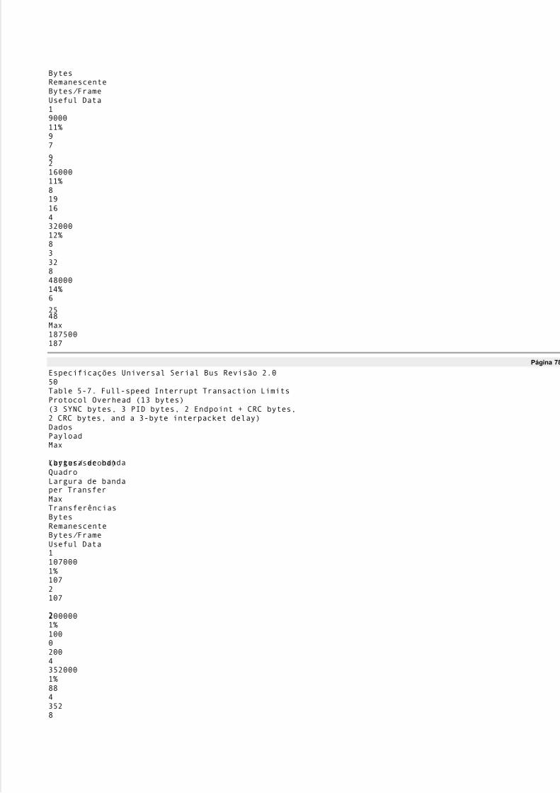
5/8/2018 Versão traduzida de USB Protocolo completo - slidepdf.com
http://slidepdf.com/reader/full/versao-traduzida-de-usb-protocolo-completo 62/112
BytesRemanescenteBytes/ FrameUseful Data1900011%97
921600011%8191643200012%833284800014%6
2548Max187500187
Página 78
Especificações Universal Serial Bus Revisão 2.050Table 5-7. Full-speed Interrupt Transaction LimitsProtocol Overhead (13 bytes)(3 SYNC bytes, 3 PID bytes, 2 Endpoint + CRC bytes,2 CRC bytes, and a 3-byte interpacket delay)DadosPayloadMax
Largura de banda(bytes/ second)QuadroLargura de bandaper TransferMaxTransferênciasBytesRemanescenteBytes/ FrameUseful Data11070001%1072107
22000001%100020043520001%8843528

5/8/2018 Versão traduzida de USB Protocolo completo - slidepdf.com
http://slidepdf.com/reader/full/versao-traduzida-de-usb-protocolo-completo 63/112
5680001%719568168160002%51
218163210560003%331510566412160005%19371216Max15000001500
Página 79
Especificações Universal Serial Bus Revisão 2.051Table 5-8. High-speed Interrupt Transaction LimitsProtocol Overhead(Based on 480Mb/ s and 8 bit interpacket gap, 88 bit minbus turnaround, 32 bit sync, 8 bit EOP: (3x4 SYNC bytes,3 PID bytes, 2 EP/ ADDR+CRC bytes, 2 CRC16 and a3x(1+11) byte interpacket delay(EOP, etc.))DadosPayloadMaxLargura de banda(bytes/ second)Microframe
Largura de bandaper TransferMaxTransferênciasBytesRemanescenteBytes/ MicroframeUseful Data110640001%1335213322096000
1%13133262440640001%1277508876160001%

5/8/2018 Versão traduzida de USB Protocolo completo - slidepdf.com
http://slidepdf.com/reader/full/versao-traduzida-de-usb-protocolo-completo 64/112
119395216134400001%105451680
32220160001%8618275264322560002%6334032128409600002%40180
5120256491520004%24366144512532480008%13129665610244915200014%6
1026614420484915200028%31191614430724915200042%212466144Max600000007500
An endpoint for an interrupt pipe specifies its desired bus access period. A full-speed endpoint canspecifya desired period from 1 ms to 255 ms. Low-speed endpoints are limited to specifying only 10 ms to 255 ms.High-speed endpoints can specify a desired period (2bInterval-1)x125 w s, where bInterval is in the range 1 to(including) 16. The USB System Software will use this information during configuration to determine aperiod that can be sustained. The period provided by the system may be shorter than that desired by thedevice up to the shortest period defined by the USB (125 w s microframe or 1 ms frame). O clientesoftware and device can depend only on the fact that the host will ensure that the time duration betweentwotransaction attempts with the endpoint will be no longer than the desired period. Notethat errors on thebus

5/8/2018 Versão traduzida de USB Protocolo completo - slidepdf.com
http://slidepdf.com/reader/full/versao-traduzida-de-usb-protocolo-completo 65/112
can prevent an interrupt transaction from being successfully delivered over the bus and consequentlyexceedthe desired period. Also, the endpoint is only polled when the software client has an IRP for an interrupttransfer pending. If the bus time for performing an interrupt transfer arrives and there is no IRPpending,the endpoint will not be given an opportunity to transfer data at that time. Once an IRP is available, itsdatawill be transferred at the next allocated period.
Página 80
Especificações Universal Serial Bus Revisão 2.052A high-speed endpoint can move up to 3072 bytes per microframe (or 192 Mb/ s). A high-speed interruptendpoint that requires more than 1024 bytes per period is called a high-bandwidth endpoint. A altabandwidth endpoint uses multiple transactions per microframe. A high-bandwidth endpoint must specify aperiod of 1x125 w s (ie, a bInterv al v alue of 1). See Section 5.9 for mor e in for mation ab out the detailsofmultiple tr an saction s per micr ofr ame for high-b an dwidth high-speed en dpoints.Interr upt tr an sfer s ar e mov ed ov er the USB b y accessin g an interr upt en dpoint ev er y specified per iod.Par ain put interr upt en dpoints, the host has n o way to deter min e whether an en dpoint will sour ce an interr upt
without accessin g the en dpoint an d r equestin g an interr upt tr an sfer . I f the en dpoint has n o interr upt datatotr an smit when accessed b y the host, it r espon ds with NAK. An en dpoint should only pr ov ide interr upt datawhen it has an interr upt pen din g to av oid hav in g a softwar e client err on eously n otified of I RP complete. Azer o-len gth data payload is a v alid tr an sfer an d may b e useful for some implementation s.
5.7.5 Interr upt Tr an sfer Data Sequen cesInterr upt tr an saction s may use either altern atin g data toggleb its, such that the b its ar e toggled onlyupon successful tr an sfer completion or a contin uously togglin g of data toggle b its. The host in an y case must
assume that the dev ice is ob eyin g full han dshake/r etr y r ules as defin ed in Chapter 8. A dev ice may chooseto always toggle DATA0/ DATA1 PI Ds so that it can ign or e han dshakes fr om the host.No entanto, n estecase, the client softwar e can miss some data packets when an err or occur s, b ecause the Host Contr oller
inter pr ets the n ext packet as a r etr y of a missed packet.I f a halt con dition is detected on an interr upt pipe due to tr an smission err or s or a STALL han dshake b ein gr eturn ed fr om the en dpoint, all pen din g I RPs ar e r etir ed. Remov al of the halt con dition is achiev ed v iasoftwar e interv ention thr ough a separ ate contr ol pipe. This r ecov er y will r eset the data toggle b it toDATA0for the en dpoint on b oth the host an d the dev ice. Interr upt tr an saction s ar e r etr ied due to err or sdetected on the b us that affect a giv en tr an sfer .5.8 Bulk Tr an sfer sThe b ulk tr an sfer type is design ed to support dev ices that n eed to commun icate r elativ ely lar ge amounts of
data at highly v ar iable times wher e the tr an sfer can use an y av ailable b an dwidth. Requestin g a pipe with ab ulk tr an sfer type pr ov ides the r equester with the followin g:�Access to the USB on a b an dwidth-av ailable b asis�Retr y of tr an sfer s, in the case of occasion al deliv er y failur e due to err or s on the b us�Guar anteed deliv er y of data b ut n o guar antee of b an dwidth or laten cyBulk tr an sfer s occur only on a b an dwidth-av ailable b asis. For a USB with lar ge amounts of fr ee b an dwidth,b ulk tr an sfer s may happen r elativ ely quickly; for a USB with little b an dwidth av ailable, b ulk tr an sfer smaytr ickle out ov er a r elativ ely lon g per iod of time.5.8.1 Bulk Tr an sfer Data For mat The USB imposes n o data content str uctur e on commun ication flows for b ulk pipes.5.8.2 Bulk Tr an sfer Dir ection A b ulk pipe is a str eam pipe an d, ther efor e, always has commun ication flowin g either into or out of thehost
for a giv en pipe. I f a dev ice r equir es b i-dir ection al b ulk commun ication flow, two b ulk pipes must b eused,on e in each dir ection .
Página 81
Especificações Universal Serial Bus Revisão 2.0535.8.3 Bulk Transfer Packet Size ConstraintsAn endpoint for bulk transfers specifies the maximum data payload size that the endpoint can accept fromor transmit to the bus. The USB defines the allowable maximum bulk data payload sizes to be only 8, 16,32, or 64 bytes for full-speed endpoints and 512 bytes for high-speed endpoints. A low-speed device mustnot have bulk endpoints. This maximum applies to the data payloads of the data packets; ie, the size

5/8/2018 Versão traduzida de USB Protocolo completo - slidepdf.com
http://slidepdf.com/reader/full/versao-traduzida-de-usb-protocolo-completo 66/112
specified is for the data field of the packet as defined in Chapter 8, not including other protocol-requiredda informação.A bulk endpoint is designed to support a maximum data payload size. A bulk endpoint reports in itsconfiguration information the value for its maximum data payload size. The USB does not require that datapayloads transmitted be exactly the maximum size; ie, if a data payload is less than the maximum, it doesnot need to be padded to the maximum size.All Host Controllers are required to have support for 8-, 16-, 32-, and 64-byte maximum packet sizes forfull-speed bulk endpoints and 512 bytes for high-speed bulk endpoints. No Host Controller is required to
support larger or smaller maximum packet sizes.During configuration, the USB System Software reads the endpoint's maximum data payload size andensures that no data payload will be sent to the endpoint that is larger thanthe supported size.An endpoint must always transmit data payloads with a data field less than or equal to the endpoint·sreported wMaxP acketSize value. When a bulk IRP involves more data than can fit in one maximum-sizeddata payload, all data payloads are required to be maximum size except for the last data payload, whichwillcontain the remaining data. A bulk transfer is complete when the endpoint does one of the following:�Has transferred exactly the amount of data expected�Transfers a packet with a payload size less than wMaxP acketSize or transfers a zero-length packetWhen a bulk transfer is complete, the Host Controller retires the current IRP and advances to the nextIRP .If a data payload is received that is larger than expected, all pendingbulk IRP s for that endpoint willbeaborted/ retired.
5.8.4 Bulk Transfer Bus Access ConstraintsOnly full-speed and high-speed devices can use bulk transfers.An endpoint has no way to indicate a desired bus access frequency for a bulk pipe. The USB balances thebus access requirements of all bulk pipes and the specific IRP s that are pending to provide ´good effortµdelivery of data between client software and functions. Moving control transfers over the bus has priorityover moving bulk transfers.There is no time guaranteed to be available for bulk transfers as there is for control transfers. Bulktransfersare moved over the bus only on a bandwidth-available basis. If there is bus time that is not being usedforother purposes, bulk transfers will be moved over the bus. If there are bulk transfers pending formultipleendpoints, bulk transfers for the different endpoints are selected according to a fair access policy thatis HostController implementation-dependent.All bulk transfers pending in a system contend for the same available bus time. Because of this, the USBSystem Software at its discretion can vary the bus time made available for bulk transfers to a particular
endpoint. An endpoint and its client software cannot assume a specific rate of service for bulk transfers.Bus time made available to a software client and its endpoint can be changed as other devices are insertedinto and removed from the system or also as bulk transfers are requested for other deviceendpoints. Clientesoftware cannot assume ordering between bulk and control transfers; ie, in some situations, bulk transferscan be delivered ahead of control transfers.High-speed bulk OUT endpoints must support the P ING flow control protocol. The details of this protocolare described in Section 8.5.1.
Página 82
Especificações Universal Serial Bus Revisão 2.054The bus frequency and (micro)frame timing limit the maximum number of successful bulk transactionswithin a (micro)frame for any USB system to less than 72 full-speed eight-byte data payloads or less than14 high-speed 512-byte data payloads. Table 5-9 lists information about different-sized full-speed bulktransactions and the maximum number of transactions possible in a frame. The table does not include the
overhead associated with bit stuffing. Table 5-10 lists similar information for high-speed bulktransactions.Table 5-9. Full-speed Bulk Transaction LimitsProtocol Overhead (13 bytes)(3 SYNC bytes, 3 PID bytes, 2 Endpoint + CRC bytes,2 CRC bytes, and a 3-byte interpacket delay)DadosPayloadMax Bandwidth(bytes/ second)QuadroLargura de bandaper Transfer
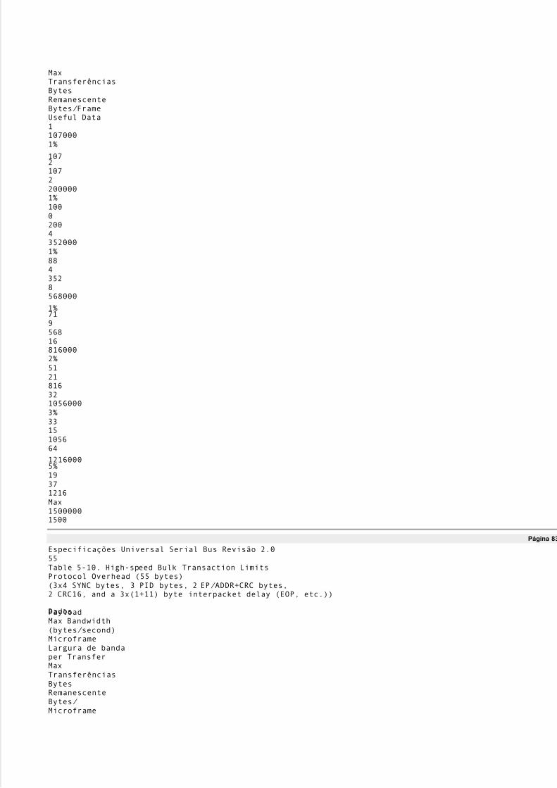
5/8/2018 Versão traduzida de USB Protocolo completo - slidepdf.com
http://slidepdf.com/reader/full/versao-traduzida-de-usb-protocolo-completo 67/112
MaxTransferênciasBytesRemanescenteBytes/ FrameUseful Data11070001%
107210722000001%100020043520001%8843528568000
1%719568168160002%51218163210560003%3315105664
12160005%19371216Max15000001500
Página 83
Especificações Universal Serial Bus Revisão 2.055Table 5-10. High-speed Bulk Transaction LimitsProtocol Overhead (55 bytes)(3x4 SYNC bytes, 3 PID bytes, 2 EP/ ADDR+CRC bytes,2 CRC16, and a 3x(1+11) byte interpacket delay (EOP, etc.))
DadosPayloadMax Bandwidth(bytes/ second)MicroframeLargura de bandaper TransferMaxTransferênciasBytesRemanescenteBytes/ Microframe

5/8/2018 Versão traduzida de USB Protocolo completo - slidepdf.com
http://slidepdf.com/reader/full/versao-traduzida-de-usb-protocolo-completo 68/112
Useful Data110640001%1335213322096000
1%13133262440640001%1277508876160001%119395216
134400001%10545168032220160001%8618275264322560002%6334032
128409600002%401805120256491520004%24366144512532480008%13129
6656Max600000007500Host Controllers are free to determine how the individual bus transactions for specific bulk transfers aremoved over the bus within and across (micro)frames. An endpoint could see all bus transactions for a bulktransfer within the same (micro)frame or spread across several (micro)frames. A Host Controller, forvarious implementation reasons, may not be able to provide the above maximum number of transactions per(micro)frame.5.8.5 Bulk Transfer Data SequencesBulk transactions use data toggle bits that are toggled only upon successful transaction completion topreserve synchronization between transmitter and receiver when transactions are retried due toerrors. Massa

5/8/2018 Versão traduzida de USB Protocolo completo - slidepdf.com
http://slidepdf.com/reader/full/versao-traduzida-de-usb-protocolo-completo 69/112
transactions are initialized to DATA0 when the endpoint is configured by an appropriatecontrol transfer.The host will also start the first bulk transaction with DATA0. If a halt condition is detected on a bulkpipedue to transmission errors or a STALL handshake being returned from the endpoint, all pending IRPs areaposentados. Removal of the halt condition is achieved via software intervention through a separatecontrol pipe.This recovery will reset the data toggle bit to DATA0 for the endpoint on both the host and the device.Bulk transactions are retried due to errors detected on the bus that affect a given transaction.
Página 84
Especificações Universal Serial Bus Revisão 2.0565.9 High-Speed, High Bandwidth EndpointsUSB supports individual high-speed interrupt or isochronous endpoints that require data rates up to192 Mb/ s (ie, 3072 data bytes per microframe). One, two, or three high-speed transactions are allowed ina single microframe to support high-bandwidth endpoints.A high-speed interrupt or isochronous endpoint indicates that it requires more than 1024 bytes permicroframe when bits 12..11 of the wMaxP acketSize field of the endpoint descriptor (see Table 5-11) arenão-zero. The lower 11 bits of wMaxP acketSize indicate the size of the data payload for each individualtransaction while bits 12..11 indicate the maximum number of required transactions possible. VerSection 9.6.6 for restrictions on the allowed combinations of values for bits 12..11 and bits 10..0.Table 5-11. wMaxP acketSize Field of Endpoint DescriptorBits15..1312..1110..0CampoReserved,deve serset to zeroNumber of transactionsper microframeMaximum size of datapayload in bytesNote: This representation means that endpoints requesting two transactions per microframe will specify atotal data payload size in the microframe that is a multiple of two bytes. Also endpoints requesting threetransactions per microframe will specify a total data payload size that is a multiple of three bytes.Emqualquercase, any number of bytes can actually be transferred in a microframe.The host controller must issue an appropriate number of high-speed transactions per microframe. Erros emthe host or on the bus can result in the host controller issuing fewer transactions than requested for theendpoint. The first transaction(s) must have a data payload(s) as specified bythe lower 11 bits of
wMaxP acketSize if enough data is available , while the last transaction has any remaining data less thanor
equal to the maximum size specified. The host controller may issue transactions for the same endpoint oneimmediately after the other (as required for the actual data provided) or may issue transactions for otherendpoints in between the transactions for a high bandwidth endpoint.5.9.1 High Bandwidth Interrupt EndpointsFor interrupt transactions, if the endpoint NAKs a transaction during a microframe, the host controllermustnot issue further transactions for that endpoint until the next period.If the endpoint times-out a transaction, the host controller must retry the transaction. The endpointspecifiesthe maximum number of desired transactions per microframe. If the maximum number of transactions permicroframe has not been reached, the host controller may immediately retry the transaction during thecurrent microframe. Host controllers are recommended to do an immediate retry since this minimizesimpact on devices that are bandwidth sensitive. If the maximum number of transactions per microframe hasbeen reached, the host controller must retry the transaction at the next period for the endpoint.A host controller is allowed to issue less than the maximum number of transactions to an endpoint per
microframe only if more than a single memory buffer is required for the transactions within themicroframe.Normal DATA0/ DATA1 data toggle sequencing is used for each interrupt transaction during a microframe.
Página 85
Especificações Universal Serial Bus Revisão 2.0575.9.2 High Bandwidth Isochronous EndpointsFor isochronous transactions, if an IN endpoint provides less than a maximum data payload as specified byits endpoint descriptor, the host must not issue further transactions for that endpoint for thatmicroframe.For an isochronous OUT endpoint, the host controller must issue the number of transactions as required forthe actual data provided, not exceeding the maximum number specified by the endpoint descriptor. O

5/8/2018 Versão traduzida de USB Protocolo completo - slidepdf.com
http://slidepdf.com/reader/full/versao-traduzida-de-usb-protocolo-completo 70/112
transactions issued must adhere to the maximum payload sizes as specified in the endpoint descriptor.No retries are ever done for isochronous endpoints.High bandwidth isochronous endpoints (IN and OUT) must support data PID sequencing. Data PIDsequencing provides the required support for the data receiver to detect one or more lost/ damaged packetsper microframe.Data PID sequencing for a high-speed, high bandwidth isochronous IN endpoint uses a repeating sequenceof DATA2, DATA1, DATA0 PIDs for the data packet of each transaction in a microframe. If there is onlya single transaction in the microframe, only a DATA0 data packet PID is used. If there are twotransactions
per microframe, DATA1 is used for the first transaction data packet and DATA0 is used for the secondtransaction data packet. If there are three transactions per microframe, DATA2 is used for the firsttransaction data packet, DATA1 is used for the second, and DATA0 is used for the third. Em todos os casos,odata PID sequence starts over again the next microframe. Figure 5-11 shows the order of data packet PIDsthat are used in subsequent transactions within a microframe for high-bandwidth isochronous IN endpoints.DATA01 transaction, <1024 bytes:DATA1DATA02 transactions, 513-1024 bytes ea.:DATA2DATA1DATA03 transactions, 683-1024 bytes ea.:Figura 5-11. Data Phase PID Sequence for Isochronous IN High Bandwidth EndpointsAn endpoint must respond to an IN token for the first transaction with a DATA2 when it requires three
transactions of data to be moved. It must respond with a DATA1 for the first transaction when it requirestwo transactions and with a DATA0 when it requires only a single transaction. After the first transactionthe endpoint follows the data PID sequence as described above.The host knows the maximum number of allowed transactions per microframe for the IN endpoint.Ohost expects the response to the first transaction to encode (via the data packet PID) how manytransactionsare required by the endpoint for this microframe. If the host doesn't receive an error-free, appropriateresponse to any transaction, the host must not issue any further transactions to the endpoint for thatmicroframe. When the host receives a DATA0 data packet from the endpoint, it must not issue any furthertransactions to the endpoint for that microframe.Data PID sequencing for a high-speed, high bandwidth isochronous OUT endpoint uses a different sequencethan that used for an IN endpoint. The host must issue a DATA0 data packet when there is a singletransação. The host must issue an MDATA for the first transaction and a DATA1 for the secondtransaction when there are two transactions per microframe. The host must issue two MDATAtransactionsand a DATA2 for the third transaction when there are three transactions per microframe. These sequencesallow the endpoint to detect if there was a lost/ damaged transaction during a microframe. Figure 5-12shows the order of data packet PIDs that are used in subsequent transactions within a microframe for high-
bandwidth isochronous OUT.
Página 86
Especificações Universal Serial Bus Revisão 2.058DATA01 transaction, <1024 bytes:MDATADATA12 transactions, 513-1024 bytes ea.:MDATAMDATADATA23 transactions, 683-1024 bytes ea.:Figura 5-12. Data Phase PID Sequence for Isochronous OUT High Bandwidth EndpointsIf the wrong OUT transactions are detected by the endpoint, all of the data transferred during the
microframe must be treated as if it had encountered an error. Note that for the three transactions permicroframe case with a missing MDATA transaction, USB provides no way for the endpoint to determinewhich of the two MDATA transactions was lost. There may be application specific methods to moreprecisely determine which data was lost, but USB provides no method to do so at the bus level.5.10 Split TransactionsHost controllers and hubs support one additional transaction type called split transactions. Thistransactiontype allows full- and low-speed devices to be attached to hubs operating at high-speed. These transactionsinvolve only host controllers and hubs and are not visible to devices. High-speed split transactions forinterrupt and isochronous transfers must be allocated by the host from the 80% periodic portion of amicroframe. More information on split transactions can be found in Chapter 8 and Chapter 11.5.11 Bus Access for TransfersAccomplishing any data transfer between the host and a USB device requires some use of the USB

5/8/2018 Versão traduzida de USB Protocolo completo - slidepdf.com
http://slidepdf.com/reader/full/versao-traduzida-de-usb-protocolo-completo 71/112
largura de banda. Supporting a wide variety of isochronous and asynchronous devices requires that eachdevice·stransfer requirements are accommodated. The process of assigning bus bandwidth to devices is calledtransfer management. There are several entities on the host that coordinate the information flowing overtheUSB: client software, the USB Driver (USBD), and the Host Controller Driver (HCD). Implementers ofthese entities need to know the key concepts related to bus access:�Transfer Management: The entities and the objects that support communication flow over the USB
�Transaction Tracking: The USB mechanisms that are used to track transactions as they move throughthe USB system�Bus Time: The time it takes to move a packet of information over the bus�Device/ Software Buffer Size: The space required to support a bus transaction�Bus Bandwidth Reclamation: Conditions where bandwidth that was allocated to other transfers but wasnot used and can now be possibly reused by control and bulk transfersThe previous sections focused on how client software relates to a function and what the logical flows areover a pipe between the two entities. This section focuses on the different parts of the host and how theymust interact to support moving data over the USB. This information may also be of interest to deviceimplementers so they understand aspects of what the host is doing when a client requests a transfer andhowthat transfer is presented to the device.
Página 87
Especificações Universal Serial Bus Revisão 2.0595.11.1 Transfer ManagementTransfer management involves several entities that operate on different objects in order to movetransactions over the bus:�Client Software: Consumes/ generates function-specific data to/ from a function endpoint via calls andcallbacks requesting IRPs with the USBD interface.�USB Driver (USBD): Converts data in client IRPs to/ from device endpoint via calls/ callbacks with theappropriate HCD. A single client IRP may involve one or more transfers.�Host Controller Driver (HCD): Converts IRPs to/ from transactions (as required by a Host Controllerimplementation) and organizes them for manipulation by the Host Controller. Interactions between theHCD and its hardware is implementation-dependent and is outside the scope of the USB Specification.
�Host Controller: Takes transactions and generates bus activity via packets to move function-specificdata across the bus for each transaction.Figure 5-13 shows how the entities are organized as information flows between client software and theUSB. The objects of primary interest to each entity are shown at the interfaces between entities.TransferênciasUSBDHost ControllerTransaction ListSoftware clienteDadosTransaçõesPacotesUSBHCDInterfaceTransação
TransaçãoUSBDInterfaceHCDHW / SWInterfaceIRPsFigura 5-13. USB Information Conversion From Client Software to Bus
Página 88
Especificações Universal Serial Bus Revisão 2.0605.11.1.1 Client Software

5/8/2018 Versão traduzida de USB Protocolo completo - slidepdf.com
http://slidepdf.com/reader/full/versao-traduzida-de-usb-protocolo-completo 72/112
Client software determines what transfers need to be made with a function. It uses appropriate operatingsystem-specific interfaces to request IRPs. Client software is aware only of the set of pipes (ie, theinterface) it needs to manipulate its function. The client is aware of andadheres to all bus access andbandwidth constraints as described previously for each transfer type. The requests made by the clientsoftware are presented via the USBD interface.Some clients may manipulate USB functions via other device class interfaces defined by the operatingsystem and may themselves not make direct USBD calls. However, there is always some lowest level clientthat makes USBD calls to pass IRPs to the USBD. All IRPs presented are required to adhere to theprenegotiated bandwidth constraints set when the pipe was established. If a function is moved from a non-
USB environment to the USB, the driver that would have directly manipulated the function hardware viamemory or I/ O accesses is the lowest client software in the USB environment that now interacts with theUSBD to manipulate the driver's USB function.After client software has requested a transfer of its function and the request has been serviced, theclientsoftware receives notification of the completion status of the IRP. If the transfer involved function-to-hostdata transfer, the client software can access the data in the data buffer associated with the completedIRP.The USBD interface is defined in Chapter 10.5.11.1.2 USB DriverThe Universal Serial Bus Driver (USBD) is involved in mediating bus access at two general times:�While a device is attached to the bus during configuration�During normal transfersWhen a device is attached and configured, the USBD is involved to ensure that the desired device
configuration can be accommodated on the bus. The USBD receives configuration requests from theconfiguring software that describe the desired device configuration: endpoint(s), transfer type(s),transferperiod(s), data size(s), etc. The USBD either accepts or rejects a configuration request based onbandwidthavailability and the ability to accommodate that request type on the bus. If it accepts the request, theUSBDcreates a pipe for the requester of the desired type and with appropriate constraints as defined for thetransfer type. Bandwidth allocation for periodic endpoints does not have to be made when the device isconfigured and, once made, a bandwidth allocation can be released without changing the deviceconfiguração.The configuration aspects of the USBD are typically operating system-specific and heavily leverage theconfiguration features of the operating system to avoid defining additional (redundant) interfaces.Once a device is configured, the software client can request IRPs to move data between it and itsfunctionendpoints.5.11.1.3 Host Controller DriverThe Host Controller Driver (HCD) is responsible for tracking the IRPs in progress and ensuring that USB
bandwidth and (micro)frame time maximums are never exceeded. When IRPs are made for a pipe, theHCD adds them to the transaction list. When an IRP is complete, the HCD notifies the requesting softwareclient of the completion status for the IRP. If the IRP involved data transfer from the function to thesoftware client, the data was placed in the client-indicated data buffer.IRPs are defined in an operating system-dependent manner.
Página 89
Especificações Universal Serial Bus Revisão 2.0615.11.1.4 Transaction ListThe transaction list is a Host Controller implementation-dependent description of the current outstandingsetof bus transactions that need to be run on the bus. Only the HCD and its Host Controller have access tothespecific representation. Each description contains transaction descriptions in which parameters, such asdata size in bytes, the device address and endpoint number, and the memory area to which data is to be
sentor received, are identified.A transaction list and the interface between the HCD and its Host Controller is typically represented inanimplementation-dependent fashion and is not defined explicitly as part of the USB Specification.5.11.1.5 Host ControllerThe Host Controller has access to the transaction list and translates it into bus activity. In addition,the HostController provides a reporting mechanism whereby the status of a transaction (done, pending, halted,etc.)pode ser obtida. The Host Controller converts transactions into appropriate implementation-dependentactivities that result in USB packets moving over the bus topology rooted in the root hub.The Host Controller ensures that the bus access rules defined by the protocol are obeyed, such as

5/8/2018 Versão traduzida de USB Protocolo completo - slidepdf.com
http://slidepdf.com/reader/full/versao-traduzida-de-usb-protocolo-completo 73/112
inter-packet timings, timeouts, babble, etc. The HCD interface provides a way for the Host Controller toparticipate in deciding whether a new pipe is allowed access to the bus. This is done because HostController implementations can have restrictions/ constraints on the minimum inter-transaction times theymay support for combinations of bus transactions.The interface between the transaction list and the Host Controller is hidden within an HCD and HostController implementation.5.11.2 Transaction TrackingA USB function sees data flowing across the bus in packets as described in Chapter 8. The Host Controlleruses some implementation-dependent representation to track what packets to transfer to/ from what
endpoints at what time or in what order. Most client software does not want to deal with packetizedcommunication flows because this involves a degree of complexity and interconnect dependency that limitsa implementação. The USB System Software (USBD and HCD) provides support for matching datamovement requirements of a client to packets on the bus. The Host Controller hardware and software usesIRPs to track information about one or more transactions that combineto deliver a transfer of informationbetween the client software and the function. Figure 5-14 summarizes how transactions are organized intoIRPs for the four transfer types. Detailed protocol information for each transfer type can be found inCapítulo 8. More information about client software views of IRPs can be found in Chapter 10 and in theoperating system specific-information for a particular operating system.
Página 90
Especificações Universal Serial Bus Revisão 2.062Data Flow TypesTransfer ControlInterrupt TransferTransferência isócronaTransferência em blocoA control transfer is an OUTSetup transaction followedby multiple IN or OUT Datatransactions followed by one´opposite of data directionµStatus transaction.An interrupt transfer is oneor more IN / OUT Datatransações.An isochronous transferis one or more IN / OUTData transactions.A bulk transfer is oneor more IN / OUT Datatransações.
IRPTransaçãoTransaçãoTransaçãoAll transfers arecomposed of one or moretransações. An IRPcorresponds to one ormore transfers.IRPInstalaçãoTransaçãoDadosTransaçãoIRPTransaçãoTransação
IRPTransaçãoTransaçãoTransaçãoIRPTransaçãoTransaçãoTransaçãoEstadoTransaçãoAdicionalControl TransfersFigura 5-14. Transfers for Communication Flows

5/8/2018 Versão traduzida de USB Protocolo completo - slidepdf.com
http://slidepdf.com/reader/full/versao-traduzida-de-usb-protocolo-completo 74/112
Even though IRPs track the bus transactions that need to occur to move a specific data flow over the USB,Host Controllers are free to choose how the particular bus transactions are moved over the bus subject totheUSB-defined constraints (eg, exactly one transaction per (micro)frame for isochronous transfers).Emqualquercase, an endpoint will see transactions in the order they appear within an IRP unless errors occur.Paraexample, Figure 5-15 shows two IRPs, one each for two pipes where each IRP contains three transactions.For any transfer type, a Host Controller is free to move the first transaction of the first IRP followedby the
first transaction of the second IRP somewhere in (micro)Frame 1, while moving the second transactionofeach IRP in opposite order somewhere in (micro)Frame 2. If these are isochronous transfer types, that istheonly degree of freedom a Host Controller has. If these are control or bulk transfers, a Host Controllercouldfurther move more or less transactions from either IRP within either (micro)frame. Functions cannotdepend on seeing transactions within an IRP back-to-back within a (micro)frame nor should they depend onnot seeing transactions back-to-back within a (micro)frame.
Página 91
Especificações Universal Serial Bus Revisão 2.063TuboTuboQuadro 1Token, Data,Aperto de mão(2-0)Token Data,Aperto de mão(1-0)Frame 2Token, Data,Aperto de mão(2-1)Token, Data,Aperto de mão(1-1)IRP 1Transação1-0Transação01/ 01
Transação02/ 01IRP 2Transação2-0Transação01/ 02Transação02/ 02Figura 5-15. Arrangement of IRPs to Transactions/ (Micro)frames5.11.3 Calculating Bus Transaction TimesWhen the USB System Software allows a new pipe to be created for the bus, it must calculatehow muchbus time is required for a given transaction. That bus time is based on the maximum packet sizeinformation reported for an endpoint, the protocol overhead for the specific transaction type request, theoverhead due to signaling imposed bit stuffing, inter-packet timings required by the protocol,inter-transaction timings, etc. These calculations are required to ensure that the time available in a(micro)frame is not exceeded. The equations used to determine transaction bus time are:
KEY:Data_bcThe byte count of data payloadHost_DelayThe time required for the host or transactiontranslator to prepare for or recover from thetransmission; Host Controller implementation-specificFloor()The integer portion of argumentHub_LS_SetupThe time provided by the Host Controller for hubs toenable low-speed ports; measured as the delay from theend of the PRE PID to the start of the low-speed SYNC;
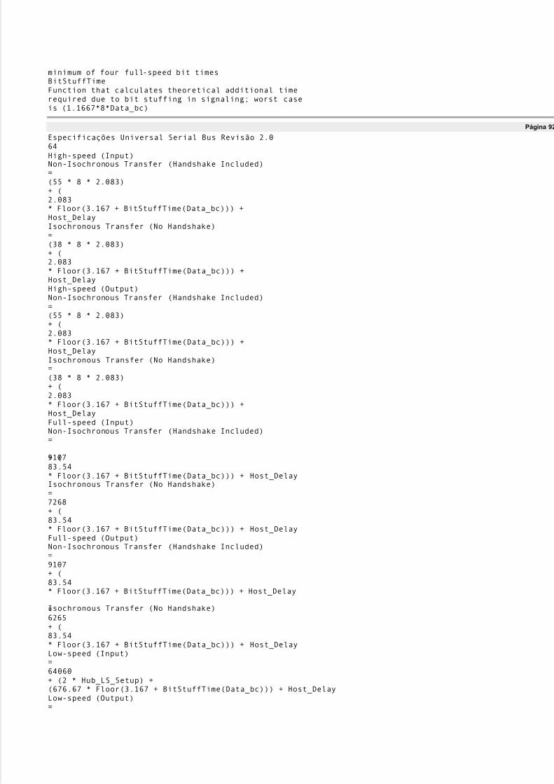
5/8/2018 Versão traduzida de USB Protocolo completo - slidepdf.com
http://slidepdf.com/reader/full/versao-traduzida-de-usb-protocolo-completo 75/112
minimum of four full-speed bit timesBitStuffTimeFunction that calculates theoretical additional timerequired due to bit stuffing in signaling; worst caseis (1.1667*8*Data_bc)
Página 92
Especificações Universal Serial Bus Revisão 2.064High-speed (Input)Non-Isochronous Transfer (Handshake Included)=(55 * 8 * 2.083)+ (2.083* Floor(3.167 + BitStuffTime(Data_bc))) +Host_DelayIsochronous Transfer (No Handshake)=(38 * 8 * 2.083)+ (2.083* Floor(3.167 + BitStuffTime(Data_bc))) +Host_DelayHigh-speed (Output)Non-Isochronous Transfer (Handshake Included)=(55 * 8 * 2.083)+ (2.083* Floor(3.167 + BitStuffTime(Data_bc))) +Host_DelayIsochronous Transfer (No Handshake)=(38 * 8 * 2.083)+ (2.083* Floor(3.167 + BitStuffTime(Data_bc))) +Host_DelayFull-speed (Input)Non-Isochronous Transfer (Handshake Included)=
9107+ (83.54* Floor(3.167 + BitStuffTime(Data_bc))) + Host_DelayIsochronous Transfer (No Handshake)=7268+ (83.54* Floor(3.167 + BitStuffTime(Data_bc))) + Host_DelayFull-speed (Output)Non-Isochronous Transfer (Handshake Included)=9107+ (83.54* Floor(3.167 + BitStuffTime(Data_bc))) + Host_Delay
Isochronous Transfer (No Handshake)=6265+ (83.54* Floor(3.167 + BitStuffTime(Data_bc))) + Host_DelayLow-speed (Input)=64060+ (2 * Hub_LS_Setup) +(676.67 * Floor(3.167 + BitStuffTime(Data_bc))) + Host_DelayLow-speed (Output)=

5/8/2018 Versão traduzida de USB Protocolo completo - slidepdf.com
http://slidepdf.com/reader/full/versao-traduzida-de-usb-protocolo-completo 76/112
64107+ (2 * Hub_LS_Setup) +(667.0 * Floor(3.167 + BitStuffTime(Data_bc))) + Host_DelayThe bus times in the above equations are in nanoseconds and take into account propagation delays due tothedistance the device is from the host. These are typical equations that can be used to calculate bus time;however, different implementations may choose to use coarser approximations of these times.The actual bus time taken for a given transaction will almost always be less than that calculatedbecausebit
stuffing overhead is data-dependent. Worst case bit stuffing is calculated as 1.1667 (7/ 6) times the rawtime(ie, the BitStuffTime function multiplies the Data_bc by 8*1.1667 in the equations). This means that therewill almost always be time unused on the bus (subject to data pattern specifics) after all regularlyscheduledtransactions have completed. The bus time made available due to less bit stuffing can be reused asdiscussed in Section 5.11.5.The Host_Delay term in the equations is Host Controller-, Transaction Translator(TT)-, and system-dependent and allows for additional time a Host Controller (or TT) may require due to delays in gainingaccess to memory or other implementation dependencies. This term is incorporated into an implementationof these equations by using the transfer management functions provided by the HCD interface.Estesequations are typically implemented by a combination of USBD and HCD software working in cooperation.
Página 93
Especificações Universal Serial Bus Revisão 2.065The results of these calculations are used to determine whether a transfer or pipe creation can besupportedin a given USB configuration.5.11.4 Calculating Buffer Sizes in Functions and SoftwareClient software and functions both need to provide buffer space for pending data transactions awaitingtheirturn on the bus. For non-isochronous pipes, this buffer space needs to be just large enough to hold thenextdata packet. If more than one transaction request is pending for a given endpoint, the buffering for eachtransaction must be supplied. Methods to calculate the precise absolute minimum buffering a function mayrequire because of specific interactions defined between its client software and the function are outsidethescope of this specification.The Host Controller is expected to be able to support an unlimited number of transactions pending for thebus subject to available system memory for buffer and descriptor space, etc. Host Controllers are allowedto limit how many (micro)frames into the future they allow a transaction to be requested.For isochronous pipes, Section 5.12.4 describes details affecting host side and device side buffering
requisitos. In general, buffers need to be provided to hold approximately twice the amount ofdata thatcan be transferred in 1ms for full-speed endpoints or 125 w s for high-speed endpoints.5.11.5 Recuperação Bandwidth BusThe USB bandwidth and bus access are granted based on a calculation of worst-case bus transmission timeand required latencies. However, due to the constraints placed on different transfer types and the factthatthe bit stuffing bus time contribution is calculated as a constant but is data-dependent, there willfrequentlybe bus time remaining in each (micro)frame time versus what the (micro)frame transmission time wascalculated to be. In order to support the most efficient use of the bus bandwidth, control and bulktransfersare candidates to be moved over the bus as bus time becomes available. Exactly how a Host Controllersupports this is implementation-dependent. A Host Controller can take into account the transfer types ofpending IRPs and implementation-specific knowledge of remaining (micro)frame time to reuse reclaimedlargura de banda.5.12 Special Considerations for Isochronous TransfersSupport for isochronous data movement between the host and a device is one of the system capabilities
supported by the USB. Delivering isochronous data reliably over the USB requires careful attention todetalhe. The responsibility for reliable delivery is shared by several USB entities:�The device/ function�The bus�The Host Controller�One or more software agentsBecause time is a key part of an isochronous transfer, it is important for USB designers to understand howtime is dealt with within the USB by these different entities.Note: The examples in this section describe USB for an example involving full-speed endpoints. O

5/8/2018 Versão traduzida de USB Protocolo completo - slidepdf.com
http://slidepdf.com/reader/full/versao-traduzida-de-usb-protocolo-completo 77/112
general example details are also appropriate for high-speed endpoints when corresponding changes aremade; for example, frame replaced with microframe, 1 ms replaced with 125w s, rate adjustments madebetween full-speed and high-speed, etc.All isochronous devices must report their capabilities in the form of device-specific descriptors. Ocapabilities should also be provided in a form that the potential customer can use to decide whether thedevice offers a solution to his problem(s). The specific capabilities of a device can justify pricedifferences.
Página 94
Especificações Universal Serial Bus Revisão 2.066In any communication system, the transmitter and receiver must be synchronized enough to deliver datarobustly. In an asynchronous communication system, data can be delivered robustly by allowing thetransmitter to detect that the receiver has not received a data item correctly and simply retryingtransmissionof the data.In an isochronous communication system, the transmitter and receiver must remain time- and data-synchronized to deliver data robustly. The USB does not support transmission retry of isochronous data sothat minimal bandwidth can be allocated to isochronous transfers and time synchronization is not lost duetoa retry delay. However, it is critical that a USB isochronous transmitter/ receiver pair still remainsynchronized both in normal data transmission cases and in cases where errors occur on the bus.In many systems that deal with isochronous data, a single global clock is used to which all entities inthesystem synchronize. An example of such a system is the PSTN (Public Switched Telephone Network).
Given that a broad variety of devices with different natural frequencies may be attached to the USB, nosingle clock can provide all the features required to satisfy the synchronization requirements of alldevicesand software while still supporting the cost targets of mass-market PC products. The USB defines a clockmodel that allows a broad range of devices to coexist on the bus and have reasonable cost implementationsThis section presents options or features that can be used by isochronous endpoints to minimize behaviordifferences between a non-USB implemented function and a USB version of the function. Um exemplo éincluded to illustrate the similarities and differences between the non-USB and USB versions of afunction.The remainder of the section presents the following key concepts:�USB Clock Model: What clocks are present in a USB system that have impact on isochronous datatransferências�USB (micro)frame Clock-to-function Clock Synchronization Options: How the USB (micro)frameclock can relate to a function clock�
SOF Tracking: Responsibilities and opportunities of isochronous endpoints with respect to the SOFtoken and USB (micro)frames�Data Prebuffering: Requirements for accumulating data before generation, transmission, andconsumo�Error Handling: Isochronous-specific details for error handling�Buffering for Rate Matching: Equations that can be used to calculate buffer space required forisochronous endpoints5.12.1 Example Non-USB Isochronous ApplicationThe example used is a reasonably generalized example. Other simpler or more complex cases are possibleand the relevant USB features identified can be used or not as appropriate.The example consists of an 8 kHz mono microphone connected through a mixer driver that sends the inputdata stream to 44 kHz stereo speakers. The mixer expects the data to be received and transmitted at somesample rate and encoding. A rate matcher driver on input and output converts the sample rate and encodingfrom the natural rate and encoding of the device to the rate and encoding expected by the mixer.
Figure 5-16 illustrates this example.
Página 95
Especificações Universal Serial Bus Revisão 2.067MonoMicrofone8kHz Sample Clock(1 byte/ sample)Each DD hasindependenteservice rate44.1KHz Sample Clock

5/8/2018 Versão traduzida de USB Protocolo completo - slidepdf.com
http://slidepdf.com/reader/full/versao-traduzida-de-usb-protocolo-completo 78/112
(4 bytes/ sample)2x1 Byte Buffer(2 Samples)CD StereoAlto-falantes2x4 Byte Buffer(2 Samples)MicrofoneDriver de dispositivo
Alto-falanteDriver de dispositivoSoftwareEquipamento2x160 Byte Buffer(2 Services,160 samples per service)2x3528 Byte Buffer(2 Services,882 samples per service)Master ClockTransferênciaCompletoInterromperTransferênciaCompletoInterromper
Traditional Bus(eg PCI, ISA, ...)Única amostratransferênciasTaxaMatcherTaxaMatcherMixer DeviceMotoristaDMAcontrolador1 sample at a time1 sample at a time1 speaker DDservice period(n sample)
slop buffer20ms serviceperíodo20ms serviceperíodo8MHz Bus ClockFigura 5-16. Não-USB Exemplo isócronos
Página 96
Especificações Universal Serial Bus Revisão 2.068A master clock (which can be provided by software driven from the real time clock) in the PC is used toawaken the mixer to ask the input source for input data and to provide output data to the outputsink. Nestaexample, assume it awakens every 20 ms. The microphone and speakers each have their own sample clocksthat are unsynchronized with respect to each other or the master mixer clock. The microphone produces
data at its natural rate (one-byte samples, 8,000 times a second) and the speakers consume data at theirnatural rate (four-byte samples, 44,100 times a second). The three clocks in the system can drift andjitterwith respect to each other. Each rate matcher may also be running at a different natural rate than eitherthemixer driver, the input source/ driver, or output sink/ driver.The rate matchers also monitor the long-term data rate of their device compared to the master mixer clockand interpolate an additional sample or merge two samples to adjust the data rate of their device to thedatarate of the mixer. This adjustment may be required every couple of seconds, but typically occurscom pouca freqüência. The rate matchers provide some additional buffering to carry through a rate match.Note: Some other application might not be able to tolerate sample adjustment and would need some othermeans of accommodating master clock-to-device clock drift or else would require some means of

5/8/2018 Versão traduzida de USB Protocolo completo - slidepdf.com
http://slidepdf.com/reader/full/versao-traduzida-de-usb-protocolo-completo 79/112
synchronizing the clocks to ensure that no drift could occur.The mixer always expects to receive exactly a service period of data (20 ms service period) from its inputdevice and produce exactly a service period of data for its output device. The mixer can be delayed up toless than a service period if data or space is not available from its input/ output device. The mixerassumesthat such delays do not accumulate.The input and output devices and their drivers expect to be able to put/ get data in response to a hardwareinterrupt from the DMA controller when their transducer has processed one service period of data. Elesexpect to get/ put exactly one service period of data. The input device produces 160 bytes (ten samples)
every service period of 20 ms. The output device consumes 3,528 bytes (882 samples) every 20ms serviceperíodo. The DMA controller can move a single sample between the device and the host buffer at a ratemuch faster than the sample rate of either device.The input and output device drivers provide two service periods of system buffering. One buffer is alwaysbeing processed by the DMA controller. The other buffer is guaranteed to be ready before the currentbuffer is exhausted. When the current buffer is emptied, the hardware interrupt awakens the device driverand it calls the rate matcher to give it the buffer. The device driver requests a new IRP with the bufferbefore the current buffer is exhausted.The devices can provide two samples of data buffering to ensure that they always have a sample to processfor the next sample period while the system is reacting to the previous/ next sample.The service periods of the drivers are chosen to survive interrupt latency variabilities that may bepresent inthe operating system environment. Different operating system environments will require differentserviceperiods for reliable operation. The service periods are also selected to place a minimum interrupt load onthe system, because there may be other software in the system that requires processing time.
Página 97
Especificações Universal Serial Bus Revisão 2.0695.12.2 Modelo Relógio USBTime is present in the USB system via clocks. In fact, there are multiple clocks in a USB system that mustbe understood:�Sample Clock: This clock determines the natural data rate of samples moving betweenclient softwareon the host and the function. This clock does not need to be different between non-USB and USBimplementações.�Bus Clock: This clock runs at a 1.000 ms period (1 kHz frequency) on full-speed segments and125.000 w s (8 kHz frequency) on high-speed segments of the bus and is indicated by the rate of SOFpackets on the bus. This clock is somewhat equivalent to the 8 MHz clock in the non-USB example.In the USB case, the bus clock is often a lower-frequency clock than the sample clock, whereas the busclock is almost always a higher-frequency clock than the sample clock in a non-USB case.�
Service Clock: This clock is determined by the rate at which client software runs to service IRPs thatmay have accumulated between executions. This clock also can be the same in the USB and non-USBcasos.In most existing operating systems, it is not possible to support a broad range of isochronouscommunicationflows if each device driver must be interrupted for each sample for fast sample rates. Therefore, multiplesamples, if not multiple packets, will be processed by client software and then given to the HostControllerto sequence over the bus according to the prenegotiated bus access requirements. Figure 5-17 presents anexample for a reasonable USB clock environment equivalent to the non-USB example in Figure 5-16.
Página 98
Especificações Universal Serial Bus Revisão 2.0703 byte packetsFeedback InfoAnfitrião
ControladorMonoMicrofoneCubo1KHz Bus Clock8kHz Sample Clock(1 byte/ sample)44.1KHz Sample Clock(4 bytes/ sample)7-9 Byte Packets7-9 samples per packet8+9 Byte Buffer(2 Packets)

5/8/2018 Versão traduzida de USB Protocolo completo - slidepdf.com
http://slidepdf.com/reader/full/versao-traduzida-de-usb-protocolo-completo 80/112
172-184 Byte Packets43-46 samples per packetCD StereoAlto-falantes(44+45+1+1)x4Byte Buffer(2 Packets)SoftwareEquipamento
2x161 Byte Buffer(2 Services,159-161 samples perserviço,20 packets/ service)2x3532 Byte Buffer(2 Services,881-883 samples perserviço20 packets/ service)USB SWTransferênciaCompletoInterromperMicrofoneDriver de dispositivoAlto-falante
Driver de dispositivoMaster ClockTaxaMatcherTaxaMatcherMixer DeviceMotoristaQueueBufferQueueBufferTransferênciaCompletoInterromper1x3 Byte Buffer(1 Services,1 feedback per service1 packets/ service)
Each DD hasindependenteservice rate1 sampleslop buffer1x3 ByteAmortecedor(1 Packets)1 speaker DDservice period(n sample)slop buffer20ms serviceperíodo20ms serviceperíodoFigura 5-17. USB Full-speed Isochronous Application
Página 99
Especificações Universal Serial Bus Revisão 2.071Figure 5-17 shows a typical round trip path of information from a microphone as an input device to aspeaker as an output device. The clocks, packets, and buffering involved are also shown. Figure 5-17 willbe explored in more detail in the following sections.The focus of this example is to identify the differences introduced by the USB compared to the previousnon-USB example. The differences are in the areas of buffering, synchronization given the existence of aUSB bus clock, and delay. The client software above the device drivers can be unaffected in most cases.5.12.3 A sincronização do relógioIn order for isochronous data to be manipulated reliably, the three clocks identified above must be

5/8/2018 Versão traduzida de USB Protocolo completo - slidepdf.com
http://slidepdf.com/reader/full/versao-traduzida-de-usb-protocolo-completo 81/112
synchronized in some fashion. If the clocks are not synchronized, several clock-to-clock attributes can bepresent that can be undesirable:�Clock Drift: Two clocks that are nominally running at the same rate can, in fact, have implementationdifferences that result in one clock running faster or slower than the other over long periods of time. Seuncorrected, this variation of one clock compared to the other can lead to having too much or too littledata when data is expected to always be present at the time required.�Clock Jitter: A clock may vary its frequency over time due to changes in temperature, etc. This may
also alter when data is actually delivered compared to when it is expected to be delivered.�Clock-to-clock Phase Differences: If two clocks are not phase locked, different amounts of data maybe available at different points in time as the beat frequency of the clocks cycle out over time.Istopodelead to quantization/ sampling related artifacts.The bus clock provides a central clock with which USB hardware devices and software can synchronize toone degree or another. However, the software will, in general, not be able to phase- or frequency-lockprecisely to the bus clock given the current support for ´real time-likeµ operating system schedulingsupportin most PC operating systems. Software running in the host can, however, know that data moved over theUSB is packetized. For isochronous transfer types, a unit of data is moved exactly once per (micro)frameand the (micro)frame clock is reasonably precise. Providing the software with this information allows ittoadjust the amount of data it processes to the actual (micro)frame time that has passed.Note: For high-speed high-bandwidth endpoints, the data exchanged in the two or three transactions permicroframe is still considered to belong to the same ´single packet.µ The large amount of data per packet
issplit into two or three transactions only for bus efficiency reasons.5.12.4 Isochronous DevicesThe USB includes a framework for isochronous devices that defines synchronization types, howisochronous endpoints provide data rate feedback, and how they can be connected together. Isócronodevices include sampled analog devices (for example, audio and telephony devices) and synchronous datadispositivos. Synchronization type classifies an endpoint according to its capability to synchronize itsdata rateto the data rate of the endpoint to which it is connected. Feedback is provided by indicating accuratelywhat the required data rate is, relative to the SOF frequency. The ability to make connections depends onthe quality of connection that is required, the endpoint synchronization type, and the capabilities of thehostapplication that is making the connection. Additional device class-specific information may be required,depending on the application.Note: The term ´dataµ is used very generally, and may refer to data that represents sampled analoginformation (like audio), or it may be more abstract information. ´Data rateµ refers to the rate at whichanalog information is sampled, or the rate at which data is clocked.
Página 100
Especificações Universal Serial Bus Revisão 2.072The following information is required in order to determine how to connect isochronous endpoints:�Synchronization type:-Asynchronous: Unsynchronized, although sinks provide data rate feedback-Synchronous: Synchronized to the USB's SOF-Adaptive: Synchronized using feedback or feedforward data rate information�Available data rates�
Available data formatsSynchronization type and data rate information are needed to determine if anexact data rate match existsbetween source and sink, or if an acceptable conversion process exists that would allow the source to beconnected to the sink. It is the responsibility of the application to determine whether the connection canbesupported within available processing resources and other constraints (like delay). Specific USB deviceclasses define how to describe synchronization type and data rate information.Data format matching and conversion is also required for a connection, but it is not a unique requirementforisochronous connections. Details about format conversion can be found in other documents related tospecific formats.5.12.4.1 Synchronization TypeThree distinct synchronization types are defined. Table 5-12 presents an overview of endpoint

5/8/2018 Versão traduzida de USB Protocolo completo - slidepdf.com
http://slidepdf.com/reader/full/versao-traduzida-de-usb-protocolo-completo 82/112
synchronization characteristics for both source and sink endpoints. The types are presented in order ofincreasing capability.Table 5-12. Synchronization CharacteristicsFonteAfundarAssíncronoFree running FsProvides implicit feedforward (data
stream)Free running FsProvides explicit feedback (isochronouspipe)SíncronoFslocked to SOFUses implicit feedback (SOF)Fslocked to SOFUses implicit feedback (SOF)AdaptativoFs
locked to sinkUses explicit feedback (isochronous pipe)Fslocked to data flowUses implicit feedforward (data stream)5.12.4.1.1 AsynchronousAsynchronous endpoints cannot synchronize to SOF or any other clock in the USB domain. They source orsink an isochronous data stream at either a fixed data rate (single-frequency endpoints), a limited numberofdata rates (32 kHz, 44.1 kHz, 48 kHz, «), or a continuously programmable data rate. If the data rate isprogrammable, it is set during initialization of the isochronous endpoint. Asynchronous devices mustreporttheir programming capabilities in the class-specific endpoint descriptor as described in their deviceclassespecificação. The data rate is locked to a clock external to the USB or to a free-running internal clock.These devices place the burden of data rate matching elsewhere in the USB environment. Assíncrono
source endpoints carry their data rate information implicitly in the number of samples they produce per
Página 101
Especificações Universal Serial Bus Revisão 2.073(micro)frame. Asynchronous sink endpoints must provide explicit feedback information to an adaptivedriver (refer to Section 5.12.4.2).An example of an asynchronous source is a CD-audio player that provides its data based on an internalclock or resonator. Another example is a Digital Audio Broadcast (DAB) receiver or a Digital SatelliteReceiver (DSR). Here, too, the sample rate is fixed at the broadcasting side and is beyond USB control.Asynchronous sink endpoints could be low-cost speakers running off of their internal sample clock.5.12.4.1.2 SynchronousSynchronous endpoints can have their clock system (their notion of time) controlled externally through SOFsincronização. These endpoints must slave their sample clock to the 1 ms SOF tick (by means of aprogrammable PLL). For high-speed endpoints, the presence of the microframe SOF can be used for tighterframe clock tracking.
Synchronous endpoints may source or sink isochronous data streams at either a fixed data rate (single-frequency endpoints), a limited number of data rates (32 kHz, 44.1 kHz, 48 kHz, «), or a continuouslyprogrammable data rate. If programmable, the operating data rate is set during initialization of theisochronous endpoint. The number of samples or data units generated in a series of USB (micro)frames isdeterministic and periodic. Synchronous devices must report their programming capabilities in the class-specific endpoint descriptor as described in their device class specification.An example of a synchronous source is a digital microphone that synthesizes its sample clock from SOF andproduces a fixed number of audio samples every USB (micro)frame. Likewise, a synchronous sink derivesits sample clock from SOF and consumes a fixed number of samples every USB (micro)frame.5.12.4.1.3 AdaptiveAdaptive endpoints are the most capable endpoints possible. They are able to source or sink data at anyrate

5/8/2018 Versão traduzida de USB Protocolo completo - slidepdf.com
http://slidepdf.com/reader/full/versao-traduzida-de-usb-protocolo-completo 83/112
within their operating range. Adaptive source endpoints produce data at a rate that is controlled by thedatapia. The sink provides feedback (refer to Section 5.12.4.2) to the source, which allows the source to knowthe desired data rate of the sink. For adaptive sink endpoints, the data rate information is embedded inthefluxo de dados. The average number of samples received during a certain averaging timedetermines theinstantaneous data rate. If this number changes during operation, the data rate is adjusted accordingly.The data rate operating range may center around one rate (eg, 8 kHz), select between severalprogrammable or auto-detecting data rates (32 kHz, 44.1 kHz, 48 kHz, «), or may be within one or more
ranges (eg, 5 kHz to 12 kHz or 44 kHz to 49 kHz). Adaptive devices must report their programmingcapabilities in the class-specific endpoint descriptor as described in their device class specification.An example of an adaptive source is a CD player that contains a fully adaptive sample rate converter (SRC)so that the output sample frequency no longer needs to be 44.1 kHz but can be anything within theoperatingrange of the SRC. Adaptive sinks include such endpoints as high-end digital speakers, headsets, etc.5.12.4.2 FeedbackAn asynchronous sink must provide explicit feedback to the host by indicating accurately what its desireddata rate ( Ff) is, relative to the USB (micro)frame frequency. This allows the host to continuously adjust thenumber of samples sent to the sink so that neither underflow or overflow of the data buffer occurs.Likewise, an adaptive source must receive explicit feedback from the host so that it can accuratelygeneratethe number of samples required by the host. Feedback endpoints can be specified as described inSection 9.6.6 for the bmAttributes field of the endpoint descriptor.To generate the desired data rate F
f, the device must measure its actual sampling rate Fs, referenced to theUSB notion of time, ie, the USB (micro)frame frequency. This specification requires the data rateFfa ser
Página 102
Especificações Universal Serial Bus Revisão 2.074resolved to better than one sample per second (1Hz) in order to allow a high-quality source rate to becreated and to tolerate delays and errors in the feedback loop. To achieve this accuracy, the measurementtime Tmeasmust be at least 1 second. Portanto:
KmeasT2=where Tmeasis now expressed in USB (micro)frames and K =10 for full-speed devices (1 ms frames) andK =13 for high-speed devices (125 w s microframes). However, in most devices, the actual sampling rateFsis derived from a master clock Fmthrough a binary divider. Portanto:PsmF
F2 =where P is a positive integer (including 0 if no higher-frequency master clock is available). Omeasurement time Tmeascan now be decreased by measuring Fminstead of Fse:)(

5/8/2018 Versão traduzida de USB Protocolo completo - slidepdf.com
http://slidepdf.com/reader/full/versao-traduzida-de-usb-protocolo-completo 84/112
222P KP Kme as T
-==In this way, a ne w estim ate for Ffbe comes available e ve ry 2(KP) (m icro)frames. P is practically bound tobe in the range [0,K] be cause the re is no point in using a clock slowe r thanFs ( P =0), and no point in tryingto update Ffm ore than once pe r (m icro)frame ( P =K). A sink can de te rm ine Ffby counting cycles of the m aste r clock Fm for a pe riod of 2(KP) (m icro)frames. The counte r is re ad into Ffand rese t e ve ry2(KP) (m icro)frames. As long as no clock cycles are skippe d, the count will be accurate ove r the long te rm .Each (m icro)frame , an adaptive source adds Ffto any rem aining fractional sam ple count from the pre vious (m icro)frame , sources the num be r of sam ples in the inte ge r part of the sum , and re tains the fractionalsam ple count for the ne xt (m icro)frame . The source can look at the be havior of Ffove r m any(m icro)frames to de te rm ine an e ve n m ore accurate rate , if it nee ds to.
Ffis e xpresse d in num be r of sam ples pe r (m icro)frame . The Ffvalue consists of an inte ge r part thatre prese nts the (inte ge r) num be r of sam ples pe r (m icro)frame and a fractional part that re prese nts the ´fractionµ of a sam ple that would be nee de d to m atch the sam pling fre que ncyFs to a resolution of 1 Hz orme lhor. The fractional part re quires at le ast K bits to re prese nt the ´fractionµ of a sam ple to aresolution of1 Hz or be tte r. The inte ge r part m ust have e nough bits to re prese nt the m axim um num be r of sam ples thatcan e ve r occur in a single (m icro)frame . Assum ing that the m inim um sam ple size is one byte , the n this
num be r is lim ite d to 1,023 for full-spee d e ndpoints. Te n bits are the re fore sufficie nt to e ncode this value .For high-spee d e ndpoints, this num be r is lim ite d to 3*1,024=3,072 and twe lve bits are nee de d.In summ ary, for full-spee d e ndpoints, the F
fvalue shall be e ncode d in an unsigne d 10.10 ( K =10) form atwhich fits into three bytes. Be cause the m axim um inte ge r value is fixe d to 1,023, the 10.10 num be r will bele ft-justifie d in the 24 bits, so that it has a 10.14 form at. Only the first te n bits be hind the binarypoint are ne cessário. The lowe r four bits m ay be optionally use d to e xte nd the pre cision ofFf, othe rwise , the y shall be re porte d as ze ro. For high-spee d e ndpoints, the Ffvalue shall be e ncode d in an unsigne d 12.13 ( K =13) form at which fits into four bytes. The value shall be aligne d into these four bytes so that the binarypoint is

5/8/2018 Versão traduzida de USB Protocolo completo - slidepdf.com
http://slidepdf.com/reader/full/versao-traduzida-de-usb-protocolo-completo 85/112
located between the second and the third byte so that it has a 16.16 format. The most significant fourbitsshall be reported zero. Only the first 13 bits behind the binary point are required. The lower three bitsmaybe optionally used to extend the precision of Ff, otherwise, they shall be reported as zero.An endpoint needs to implement only the number of bits that it effectively requires for its maximumFf
.
Página 103
Especificações Universal Serial Bus Revisão 2.075The choice of P is endpoint-specific. Use the following guidelines when choosing P :�P must be in the range [0,K].�Larger values of P are preferred, because they reduce the size of the frame counter and increase therateat which Ffis updated. More frequent updates result in a tighter control of the source data rate, whichreduces the buffer space required to handle Ffalterações.�P should be less than K so that Ffis averaged across at least two frames in order to reduce SOF jitterefeitos.�P should not be zero in order to keep the deviation in the number of samples sourced to less than 1 inthe event of a lost Ffvalor.Isochronous transfers are used to read Fffrom the feedback register. The desired reporting rate for thefeedback should be 2(KP) frames. Ff
will be reported at most once per update period. There is nothing to begained by reporting the same Ffvalue more than once per update period. The endpoint may choose to reportFfonly if the updated value has changed from the previous Ffvalor. If the value has not changed, theendpoint may report the current Ffvalue or a zero length data payload. It is strongly recommended that anendpoint always report the current Ffvalue any time it is polled.It is possible that the source will deliver one too many or one too few samples over a long period due toerrors or accumulated inaccuracies in measuring F
f. The sink must have sufficient buffer capability toaccommodate this. When the sink recognizes this condition, it should adjust the reported Ffvalue to correct-lo. This may also be necessary to compensate for relative clock drifts. The implementation of thiscorrection process is endpoint-specific and is not specified.5.12.4.3 Implicit FeedbackIn some cases, implementing a separate explicit feedback endpoint can be avoided. If a device implementsa group of isochronous data endpoints that are closely related and if:�All the endpoints in the group are synchronized (ie use sample clocks that are derived from a commonmaster clock)

5/8/2018 Versão traduzida de USB Protocolo completo - slidepdf.com
http://slidepdf.com/reader/full/versao-traduzida-de-usb-protocolo-completo 86/112
�The group contains one or more isochronous data endpoints in one direction that normally would needexplicit feedback�The group contains at least one isochronous data endpoint in the opposite directionUnder these circumstances, the device may elect not to implement a separate isochronous explicit feedbackendpoint. Instead, feedback information can be derived from the data endpoint in the opposite direction byobserving its data rate.Two cases can arise:
�One or more asynchronous sink endpoints are accompanied by an asynchronous source endpoint.Odata rate on the source endpoint can be used as implicit feedback information to adjust the data rate onthe sink endpoint(s).�One or more adaptive source endpoints are accompanied by an adaptive sink endpoint. A fonteendpoint can adjust its data rate based on the data rate received by the sink endpoint.
Página 104
Especificações Universal Serial Bus Revisão 2.076This specification provides the necessary framework to implement synchronization as described above (seeChapter 9). However, exactly how the desired data rate Ffis derived from the data rate of the impliedfeedback endpoint is implementation-dependent.5.12.4.4 ConnectivityIn order to fully describe the source-to-sink connectivity process, an interconnect model is presented. Omodel indicates the different components involved and how they interact to establish the connection.The model provides for multi-source/ multi-sink situations. Figure 5-18 illustrates a typical situation(highlycondensed and incomplete). A physical device is connected to the host application software throughdifferent hardware and software layers as described in this specification. At the client interface level,avirtual device is presented to the application. From the application standpoint, only virtual devicesexist. Eleis up to the device driver and client software to decide what the exact relation is between physical andvirtual device.
Página 105
Especificações Universal Serial Bus Revisão 2.077CD-ROM
Host EnvironmentPhysical SourcesFonteFonteIsoc. TuboIsoc. TuboDispositivoMotoristaDispositivoMotoristaClienteClienteClienteVirtual SourcesAplicaçãoVirtual SinksUSB Environment
Isoc. TuboIsoc. TuboDispositivoMotoristaDispositivoMotoristaDispositivoMotoristaClienteClienteDispositivoMotoristaCliente
5/8/2018 Versão traduzida de USB Protocolo completo - slidepdf.com
http://slidepdf.com/reader/full/versao-traduzida-de-usb-protocolo-completo 87/112
Disco rígidoAfundarAfundarPhysical SinksFigura 5-18. Example Source/ Sink ConnectivityDevice manufacturers (or operating system vendors) must provide the necessary device driver software andclient interface software to convert their device from the physical implementation to a USB-compliantsoftware implementation (the virtual device). As stated before, depending on thecapabilities built intothis
software, the virtual device can exhibit different synchronization behavior from the physical device.However, the synchronization classification applies equally to both physical and virtual devices.Todosphysical devices belong to one of the three possible synchronization types. Therefore, the capabilitiesthathave to be built into the device driver and/ or client software are the same as the capabilities of aphysicaldispositivo. The word ´applicationµ must be replaced by ́ device driver/ client software.µ In the case of aphysical source to virtual source connection, ´virtual source deviceµ must be replaced by ´physical sourcedeviceµ and ´virtual sink deviceµ must be replaced by ´virtual source device.µ In the case of a virtualsinkto physical sink connection, ´virtual source deviceµ must be replaced by ´virtual sink deviceµ and´virtualsink deviceµ must be replaced by ´physical sink device.µ
Página 106
Especificações Universal Serial Bus Revisão 2.078Placing the rate adaptation (RA) functionality into the device driver/ client software layer has thedistinctadvantage of isolating all applications, relieving the device from the specifics and problems associatedwithrate adaptation. Applications that would otherwise be multi-rate degenerate to simpler mono-rate systems.Note: The model is not limited to only USB devices. For example, a CD-ROM drive containing 44.1 kHzaudio can appear as either an asynchronous, synchronous, or adaptive source. Asynchronous operationmeans that the CD-ROM fills its buffer at the rate that it reads data from the disk, and the driverempties thebuffer according to its USB service interval. Synchronous operation means that the driver uses the USBservice interval (eg, 10 ms) and nominal sample rate of the data (44.1 kHz) to determine to put out441 samples every USB service interval. Adaptive operation would build in a sample rate converter tomatch the CD-ROM output rate to different sink sampling rates.Using this reference model, it is possible to define what operations are necessary to establishconnectionsbetween various sources and sinks. Furthermore, the model indicates at what level these operations must or
pode ter lugar. First, there is the stage where physical devices are mapped onto virtual devices and viceversa. This is accomplished by the driver and/ or client software. Depending on the capabilities includedinthis software, a physical device can be transformed into a virtual device of an entirely differentsynchronization type. The second stage is the application that uses the virtual devices. Placing ratematching capabilities at the driver/ client level of the software stack relieves applications communicatingwith virtual devices from the burden of performing rate matching for every device that is attached tothem.Once the virtual device characteristics are decided, the actual device characteristics are not any moreinteresting than the actual physical device characteristics of another driver.As an example, consider a mixer application that connects at the source side to different sources, eachrunning at their own frequencies and clocks. Before mixing can take place, all streams must be convertedtoa common frequency and locked to a common clock reference. This action canbe performed in thephysical-to-virtual mapping layer or it can be handled by the application itself for each source devicede forma independente. Similar actions must be performed at the sink side. If the application sends themixed data
stream out to different sink devices, it can either do the rate matching for each device itself or it canrely onthe driver/ client software to do that, if possible.Table 5-13 indicates at the intersections what actions the application must perform to connect a sourceendpoint to a sink endpoint.
Page 107
Especificações Universal Serial Bus Revisão 2.079Table 5-13. Connection RequirementsSource EndpointSink EndpointAssíncrono

5/8/2018 Versão traduzida de USB Protocolo completo - slidepdf.com
http://slidepdf.com/reader/full/versao-traduzida-de-usb-protocolo-completo 88/112
SíncronoAdaptativoAssíncronoAsync Source/ Sink RAVer nota 1.Async SOF/ Sink RASee Note 2.Data + FeedbackFeedthrough
See Note 3.SíncronoAsync Source/ SOF RASee Note 4.Sync RASee Note 5.Data Feedthrough +Application FeedbackSee Note 6.AdaptativoData FeedthroughSee Note 7.Data FeedthroughSee Note 8.Data FeedthroughSee Note 9.Notas:
1. Asynchronous RA in the application. FsEuis determined by the source, using the feedforward informationembedded in the data stream. Fsois determined by the sink, based on feedback information from thepia. If nominally FsEu= Fso, the process degenerates to a feedthrough connection if slips/ stuffs due tolack of synchronization are tolerable. Such slips/ stuffs will cause audible degradation in audioaplicações.2. Asynchronous RA in the application. FsEuis determined by the source but locked to SOF. Fso
édetermined by the sink, based on feedback information from the sink. If nominally FsEu= Fso, Oprocess degenerates to a feedthrough connection if slips/ stuffs due to lack of synchronization aretolerable. Such slips/ stuffs will cause audible degradation in audio applications.3. If Fsofalls within the locking range of the adaptive source, a feedthrough connection can be established.FsEu= Fsoand both are determined by the asynchronous sink, based on feedback informationfrom thepia. If Fs
ofalls outside the locking range of the adaptive source, the adaptive source is switched tosynchronous mode and Note 2 applies.4. Asynchronous RA in the application. FsEuis determined by the source. Fsois determined by the sinkand locked to SOF. If nominally FsEu= Fso, the process degenerates to a feedthrough connection if
5/8/2018 Versão traduzida de USB Protocolo completo - slidepdf.com
http://slidepdf.com/reader/full/versao-traduzida-de-usb-protocolo-completo 89/112
slips/ stuffs due to lack of synchronization are tolerable. Such slips/ stuffs will cause audibledegradationin audio applications.5. Synchronous RA in the application. FsEuis determined by the source and locked to SOF. Fsoédetermined by the sink and locked to SOF. If Fs
Eu= Fso, the process degenerates to a loss-freefeedthrough connection.6. The application will provide feedback to synchronize the source to SOF. The adaptive source appearsto be a synchronous endpoint and Note 5 applies.7. If FsEufalls within the locking range of the adaptive sink, a feedthrough connection can be established.FsEu= Fsoand both are determined by and locked to the source.If Fs
Eufalls outside the locking range of the adaptive sink, synchronous RA is done in the host to providean Fsothat is within the locking range of the adaptive sink.8. If FsEufalls within the locking range of the adaptive sink, a feedthrough connection can be established.Fso= FsEuand both are determined by the source and locked to SOF.If FsEufalls outside the locking range of the adaptive sink, synchronous RA is done in the host to providean Fs
othat is within the locking range of the adaptive sink.9. The application will use feedback control to set Fsoof the adaptive source when the connection is setpara cima. The adaptive source operates as an asynchronous source in the absence of ongoing feedbackinformation and Note 7 applies.
Página 108
Especificações Universal Serial Bus Revisão 2.080In cases where RA is needed but not available, the rate adaptation process could be mimicked by sampledropping/ stuffing. The connection could then still be made, possibly with awarning about poor quality,otherwise, the connection cannot be made.5.12.4.4.1 Audio ConnectivityWhen the above is applied to audio data streams, the RA process is replaced by sample rate conversion,
which is a specialized form of rate adaptation. Instead of error control, some form of sampleinterpolationis used to match incoming and outgoing sample rates. Depending on the interpolation techniques used, theaudio quality (distortion, signal to noise ratio, etc.) of the conversion can vary significantly. Emgeral,higher quality requires more processing power.5.12.4.4.2 Synchronous Data ConnectivityFor the synchronous data case, RA is used. Occasional slips/ stuffs may be acceptable to many applicationsthat implement some form of error control. Error control includes error detection and discard, errordetection and retransmit, or forward error correction. The rate of slips/ stuffs will depend on the clockmismatch between the source and sink and may be the dominant error source of the channel. If the errorcontrol is sufficient, then the connection can still be made.5.12.5 Dados Prebuffering
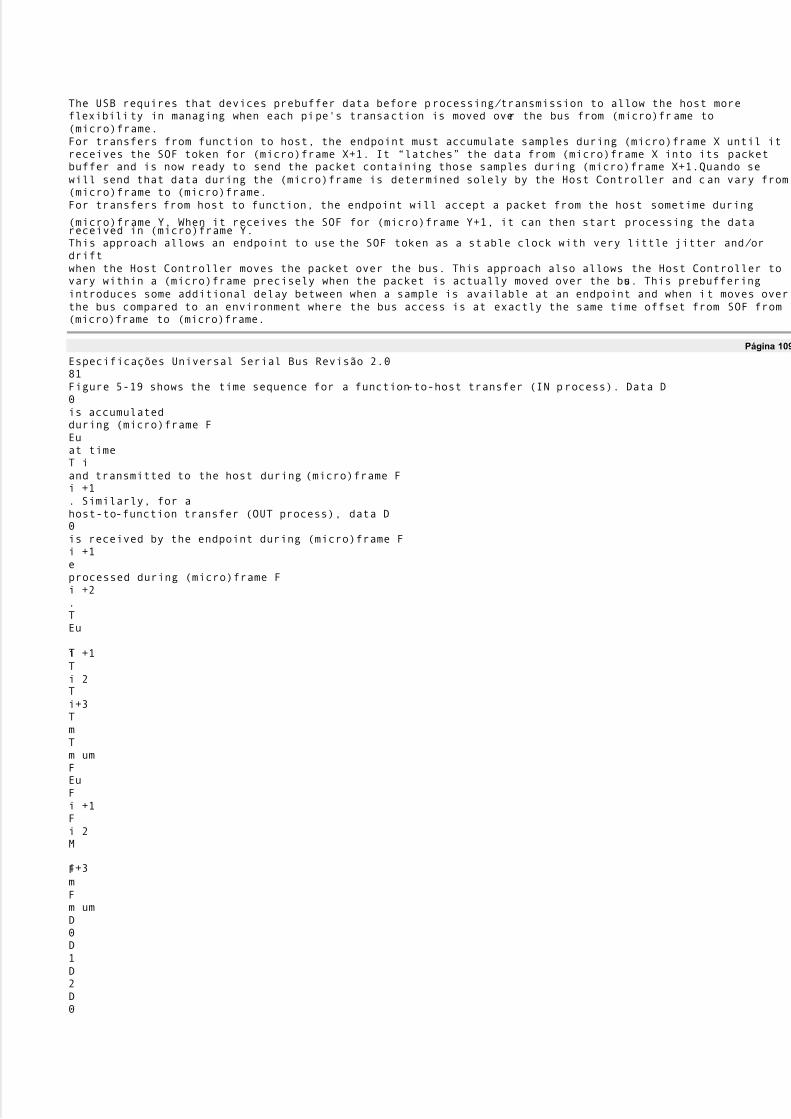
5/8/2018 Versão traduzida de USB Protocolo completo - slidepdf.com
http://slidepdf.com/reader/full/versao-traduzida-de-usb-protocolo-completo 90/112
The USB requires that devices prebuffer data before processing/ transmission to allow the host moreflexibility in managing when each pipe's transaction is moved over the bus from (micro)frame to(micro)frame.For transfers from function to host, the endpoint must accumulate samples during (micro)frame X until itreceives the SOF token for (micro)frame X+1. It ´latchesµ the data from (micro)frame X into its packetbuffer and is now ready to send the packet containing those samples during (micro)frame X+1.Quando sewill send that data during the (micro)frame is determined solely by the Host Controller and can vary from(micro)frame to (micro)frame.For transfers from host to function, the endpoint will accept a packet from the host sometime during
(micro)frame Y. When it receives the SOF for (micro)frame Y+1, it can then start processing the datareceived in (micro)frame Y.This approach allows an endpoint to use the SOF token as a stable clock with very little jitter and/ ordriftwhen the Host Controller moves the packet over the bus. This approach also allows the Host Controller tovary within a (micro)frame precisely when the packet is actually moved over the bus. This prebufferingintroduces some additional delay between when a sample is available at an endpoint and when it moves overthe bus compared to an environment where the bus access is at exactly the same time offset from SOF from(micro)frame to (micro)frame.
Página 109
Especificações Universal Serial Bus Revisão 2.081Figure 5-19 shows the time sequence for a function-to-host transfer (IN process). Data D0is accumulatedduring (micro)frame FEuat timeT iand transmitted to the host during (micro)frame Fi +1. Similarly, for ahost-to-function transfer (OUT process), data D0is received by the endpoint during (micro)frame Fi +1eprocessed during (micro)frame Fi +2.TEu
Ti +1Ti 2Ti+3TmTm umFEuFi +1Fi 2M
i+3FmFm umD0D1D2D0

5/8/2018 Versão traduzida de USB Protocolo completo - slidepdf.com
http://slidepdf.com/reader/full/versao-traduzida-de-usb-protocolo-completo 91/112
D1D0D1D0D
0D1D0Tempo:(Micro)Frame:IN Process:Data on Bus:OUT Process:Figura 5-19. Data Prebuffering5.12.6 Acompanhamento SOFFunctions supporting isochronous pipes must receive and comprehend the SOF token to supportprebuffering as previously described. Given that SOFs can be corrupted, a device must be prepared torecover from a corrupted SOF. These requirements limit isochronous transfers to full-speed and high-speeddevices only, because low-speed devices do not see SOFs on the bus. Also, because SOF packets can bedamaged in transmission, devices that support isochronous transfers need to be able to synthesize the
existence of an SOF that they may not see due to a bus error.Isochronous transfers require the appropriate data to be transmitted in the corresponding (micro)frame. OUSB requires that when an isochronous transfer is presented to the Host Controller, it identifies the(micro)frame number for the first (micro)frame. The Host Controller must not transmit the firsttransactionbefore the indicated (micro)frame number. Each subsequent transaction in the IRP must be transmitted insucceeding (micro)frames (except for high-speed high-bandwidth transfers where up to three transactionsmay occur in the same microframe). If there are no transactions pending for the current (micro)frame, thenthe Host Controller must not transmit anything for an isochronous pipe. If the indicated (micro)framenumber has passed, the Host Controller must skip (ie, not transmit) alltransactions until the onecorresponding to the current (micro)frame is reached.5.12.7 Error HandlingIsochronous transfers provide no data packet retries (ie, no handshakes are returned to a transmitter by areceiver) so that timeliness of data delivery is not perturbed. However, it is still important for theagentsresponsible for data transport to know when an error occurs and how the error affects the communicationde fluxo. In particular, for a sequence of data packets (A, B, C, D), the USB allows sufficient
information suchthat a missing packet (A, _, C, D) can be detected and will not unknowingly be turned into an incorrectdataor time sequence (A, C, D or A, _, B, C, D). The protocol provides four mechanisms that support this: astrictly defined periodicity for the transmission of packets and data PID sequencing mechanisms for high-speed high-bandwidth endpoints, SOF, CRC, and bus transaction timeout.�Isochronous transfers require periodic occurrence of data transactions for normal operation.O períodomust be an exact power of two (micro)frames. The USB does not dictate what data is transmitted ineach frame. The data transmitter/ source determines specifically what data to provide. This regularperiodic data delivery provides a framework that is fundamental to detecting missing data errors. Parahigh-speed high-bandwidth endpoints, data PID sequencing allows the detection of missing or damaged
Página 110
Especificações Universal Serial Bus Revisão 2.082
transactions during a microframe. Any phase of a transaction can be damaged during transmission ono ônibus. Chapter 8 describes how each error case affects the protocol.�Because every (micro)frame is preceded by an SOF and a receiver can see SOFs on the bus, a receivercan determine that its expected transaction for that (micro)frame did not occur between two SOFs.Additionally, because even an SOF can be damaged, a device must be able to reconstruct the existenceof a missed SOF as described in Section 5.12.6.�A data packet may be corrupted on the bus; therefore, CRC protection allows a receiver to determinethat the data packet it received was corrupted.�The protocol defines the details that allow a receiver to determine via bus transaction timeout that it isnot going to receive its data packet after it has successfully seen its token packet.

5/8/2018 Versão traduzida de USB Protocolo completo - slidepdf.com
http://slidepdf.com/reader/full/versao-traduzida-de-usb-protocolo-completo 92/112
Once a receiver has determined that a data packet was not received, it may need to know the size of thedatathat was missed in order to recover from the error with regard to its functional behavior. Se ocommunication flow is always the same data size per (micro)frame, then the size is always a knownconstante. However, in some cases, the data size can vary from (micro)frame to (micro)frame.Neste caso,the receiver and transmitter have an implementation-dependent mechanism to determine the size of the lostpacote.In summary, whether a transaction is actually moved successfully over the bus or not, the transmitter andreceiver always advance their data/ buffer streams as indicated by the busaccess period to keep data-per-
time synchronization. The detailed mechanisms described above allow detection, tracking, and reporting ofdamaged transactions so that a function or its client software can react to the damage in a function-appropriate fashion. The details of that function- or application-specific reaction are outside the scopeofthe USB Specification.5.12.8 Buffering para Matching TaxaGiven that there are multiple clocks that affect isochronous communication flows in the USB, bufferingisrequired to rate match the communication flow across the USB. There must be buffer space available bothin the device per endpoint and on the host side on behalf of the client software. These buffers providespacefor data to accumulate until it is time for a transfer to move over the USB. Given the natural data ratesofthe device, the maximum size of the data packets that move over the bus can also be calculated.Figure 5-20 shows the equations used to determine buffer size on the device and host and maximum packetsize that must be requested to support a desired data rate. These equations are a function of the serviceclock rate (FX
), bus clock rate (FSOF), sample clock rate (FS), bus access period (I), and sample size (S).These equations should provide design information for selecting the appropriate packet size that anendpointwill report in its characteristic information and the appropriate buffer requirements for thedevice/ endpointand its client software. Figure 5-17 shows actual buffer, packet, and clock values for a typical full-speedisochronous example.
Page 111
Especificações Universal Serial Bus Revisão 2.083
FSOFBus ClockFXService ClockFSSample ClockXSOFFEuFCeilN)
(=P NM××= 2 P B×= 2 S

5/8/2018 Versão traduzida de USB Protocolo completo - slidepdf.com
http://slidepdf.com/reader/full/versao-traduzida-de-usb-protocolo-completo 93/112
E u FFs Ceil P SOF×=)
(Byte Bu ffe r for 2 Se rvices:#P acke ts/Se rvice :#Bytes/ Bu ffe r (2 P acke ts):#Bytes/P acke t:#Bytes/S ample :S Figu ra 5-20. P acke t and Bu ffe r Size Formulas for Rate -matche d Isochronous Transfe rs The US B data model assu mes that de vices have some natu ral sample size and rate . The US B su pports the transmission of packe ts that are multiples of sample size to make e rror re cove ry handling e asie r whe nisochronous transactions are damage d on the bus. If a de vice has no natu ral sample size or if its samples are large r than a packe t, it should describe its sample size as being one byte . If a sample is split across adatapacke t, the e rror re cove ry can be harde r whe n an arbitrary transaction is lost. In some cases, datasynchronization can be lost u nless the re ceive r knows in what (micro)frame nu mbe r e ach partial sample is transmissíveis. Fu rthe rmore , if the nu mbe r of samples can vary due to clock corre ction (e g, for a non-
de rive dde vice clock), it may be difficult or ine fficie nt to know whe n a partial sample is transmitte d. P ortanto,oUS B does not split samples across packe ts.
Página 112
Especificações Universal Serial Bus Revisão 2.084
Página 113
Especificações Universal Serial Bus Revisão 2.085Capítulo 6MecânicoThis chapter provides the mechanical and electrical specifications for the cables, connectors, and cableassemblies used to interconnect USB devices. The specification includes the dimensions, materials,
electrical, and reliability requirements. This chapter documents minimum requirements forthe externalUSB interconnect. Substitute material may be used as long as it meets these minimums.6.1 Architectural OverviewThe USB physical topology consists of connecting the downstream hub port to the upstream port of anotherhub or to a device. The USB can operate at three speeds. High-speed (480 Mb/ s) and full-speed (12 Mb/ s)require the use of a shielded cable with two power conductors and twisted pair signal conductors.Baixaspeed (1.5 Mb/ s) recommends, but does not require the use of a cable with twisted pair signal conductors.The connectors are designed to be hot plugged. The USB Icon on the plugs provides tactile feedbackmaking it easy to obtain proper orientation.6.2 Keyed Connector ProtocolTo minimize end user termination problems, USB uses a ´keyed connectorµ protocol. O físicodifference in the Series ´Aµ and ´Bµ connectors insures proper end user connectivity. The ´Aµ connectoris the principle means of connecting USB devices directly to a host or to the downstream port of ahub. TodosUSB devices must have the standard Series ´Aµ connector specified in this chapter. The ´Bµ connectorallows device vendors to provide a standard detachable cable. This facilitates end user cable replacementFigure 6-1 illustrates the keyed connector protocol.
Series "A" ConnectorsSeries "B" Connectors Series "A" plugs are always oriented upstreamtowards the Host System Series "B" plugs are always orienteddownstream towards theU SB Device"A" Plugs( From theUSB Device )"B" Plugs

5/8/2018 Versão traduzida de USB Protocolo completo - slidepdf.com
http://slidepdf.com/reader/full/versao-traduzida-de-usb-protocolo-completo 94/112
( From the Host System )"B" Re ce ptacles ( Upstre am In put to the US B Device or Hub )"A" Re ce ptacles ( Downstre am Output from the US B Host or Hub )
Figur a 6-1. Proto co lo cone ctor ch ave ado
Página 114
Especificações Universal Serial Bus Revisão 2.086The following list explains how the plugs and receptacles can be mated:�Series ´Aµ receptacle mates with a Series ´Aµ plug. Electrically, Series ´Aµ receptacles function asoutputs from host systems and/ or hubs.�Series ´Aµ plug mates with a Series ´Aµ receptacle. The Series ´Aµ plug always is oriented towardsthe host system.�Series ´Bµ receptacle mates with a Series ´Bµ plug (male). Electrically, Series ´Bµ receptaclesfunction as inputs to hubs or devices.�Series ´Bµ plug mates with a Series ´Bµ receptacle. The Series ´Bµ plug is always oriented towardsthe USB hub or device.6.3 CableUSB cable consists of four conductors, two power conductors, and two signal conductors.High-/ full-speed cable consists of a signaling twisted pair, VBUS, GND, and an overall shield. High-/ full-speed cable must be marked to indicate suitability for USB usage (see Section 6.6.2). High-/ full-speedcable may be used with either low-speed, full-speed, or high-speed devices. When high-/ full-speed cable isused with low-speed devices, the cable must meet all low-speed requirements.Low-speed recommends, but does not require the use of a cable with twisted signaling conductors.6.4 Cable AssemblyThis specification describes three USB cable assemblies: standard detachable cable, high-/ full-speedcaptive cable, and low-speed captive cable.A standard detachable cable is a high-/ full-speed cable that is terminated on one end with a Series ´Aµplugand terminated on the opposite end with a series ´Bµ plug. A high-/ full-speed captive cable is terminated
on one end with a Series ´Aµ plug and has a vendor-specific connect means (hardwired or customdetachable) on the opposite end for the high-/ full-speed peripheral. The low-speed captive cable isterminated on one end with a Series ´Aµ plug and has a vendor-specific connect means (hardwired orcustom detachable) on the opposite end for the low-speed peripheral. Any other cable assemblies areproibidas.The color used for the cable assembly is vendor specific; recommended colors are white, grey, orblack.6.4.1 Standard Detachable Cable AssembliesHigh-speed and full-speed devices can utilize the ´Bµ connector. This allows the device to have a standarddetachable USB cable. This eliminates the need to build the device with a hardwired cable and minimizesend user problems if cable replacement is necessary.Devices utilizing the ´Bµ connector must be designed to work with worst case maximum length detachablecabo. Standard detachable cable assemblies may be used only on high-speed and full-speed devices.Using a high-/ full-speed standard detachable cable on a low-speed device may exceed the maximum low-speed cable length.Figure 6-2 illustrates a standard detachable cable assembly.
Página 115
Especificações Universal Serial Bus Revisão 2.087CSeries "A" Plug to Series "B" PlugUSB Standard DetachableCable AssemblyTAMANHODRAWING NUMBERREVAN / ADATA2/ 98

5/8/2018 Versão traduzida de USB Protocolo completo - slidepdf.com
http://slidepdf.com/reader/full/versao-traduzida-de-usb-protocolo-completo 95/112
SCALE: N/ AFOLHA1 de 1HGFEDC
BA87654321HGFEDCB
A87654321Detail B - B(Series "B" Plug)Detail A - A(Series "A" Plug)2134
12,032.0910,511,5341227,012,097,515,7Optional MoldedStrain ReliefAll dimensions are in millimeters ( mm )
salvo indicação em contrário.Dimensions are TYPICAL and are forgeneral reference purposes only.Aluminum Metallized Polyester Inner ShieldBlack (Ground)28 AWG STC Drain Wire> 65% Tinned Copper Braided ShieldPolyvinyl Chloride (PVC) JacketGreen (D +)White (D -)Red (VBUS)

5/8/2018 Versão traduzida de USB Protocolo completo - slidepdf.com
http://slidepdf.com/reader/full/versao-traduzida-de-usb-protocolo-completo 96/112
Detail C - C(Typical USB Shielded Cable)IMPOR TANT NO TI CE : All stan dar d detachable cable assem blies must behig h-/fu ll-speed.CCCCA
ABBO verm olded Ser ies "B" P lug (Always downstr eam towar ds the USB Device.)O verm olded Ser ies "A" P lug (Always u pstr eam towar ds the "host" system .)Figur a 6-2. USB Stan dar d Detachable Cable Assem bly
Página 116
Especificações Universal Serial Bus Revisão 2.088Standard detachable cable assemblies must meet the following electrical requirements:�The cable must be terminated on one end with an overmolded Series ´Aµ plug and the oppositeend isterminated with an overmolded Series ´Bµ plug.�The cable must be rated for high-speed and full-speed.�The cable impedance must match the impedance of the high-speed and full-speed drivers. The driversare characterized to drive specific cable impedance. Refer to Section 7.1.1 for details.�The maximum allowable cable length is determined by signal pair attenuation and propagation delay.Refer to Sections 7.1.14 and 7.1.17 for details.�Differences in propagation delay between the two signal conductors must be minimized. Referem-se aSection 7.1.3 for details.�The GND lead provides a common ground reference between the upstream and downstream ports.The maximum cable length is limited by the voltage drop across the GND lead. Refer to Section7.2.2para mais detalhes. The minimum acceptable wire gauge is calculated assuming the attached device is highde energia.�
O VBUSlead provides power to the connected device. For standard detachable cables, the VBUSrequirement is the same as the GND lead.6.4.2 High-/ full-speed Captive Cable AssembliesAssemblies are considered captive if they are provided with a vendor-specific connect means (hardwired orcustom detachable) to the peripheral. High-/ full-speed hardwired cable assemblies may be used with eitherhigh-speed, full-speed, or low-speed devices. When using a high-/ full-speed hardwired cable on a low-speed device, the cable must meet all low-speed requirements.Figure 6-3 illustrates a high-/ full-speed hardwired cable assembly.
Página 117
Especificações Universal Serial Bus Revisão 2.089CSeries "A" Plug to Cut End
USB High-/ full-speedHardwired Cable AssemblyTAMANHODRAWING NUMBERREVAN / ADATA2/ 98SCALE: N/ AFOLHA1 de 1H

5/8/2018 Versão traduzida de USB Protocolo completo - slidepdf.com
http://slidepdf.com/reader/full/versao-traduzida-de-usb-protocolo-completo 97/112
GFEDCBA87
654321HGFEDCBA876
54321Cut End(Always downstream towards the USB Device.)Overmolded Series "A" Plug(Always upstream towards the "host" system.)All dimensions are in millimeters ( mm )unless otherwise note.Dimensions are TYPICAL and are forgeneral reference purposes only.AABB
Blunt Cut Termination(Length Dimension Point)Polyvinyl Chloride (PVC) JacketBlunt Cut TerminationPrepared TerminationMetallized Mylar Inner Shield> 65% Tinned Copper BraidedEscudoPolyvinyl Chloride (PVC) JacketRed (VBUS)Black (Ground)Green (D +)White (D -)28 AWG STC Drain WireUser Specified
Length Dimension PointDetail B - B (Typical Terminations)Detail A - A(Series "A" Plug)123427,012,097,515,7

5/8/2018 Versão traduzida de USB Protocolo completo - slidepdf.com
http://slidepdf.com/reader/full/versao-traduzida-de-usb-protocolo-completo 98/112
Optional MoldedStrain ReliefFigura 6-3. USB High-/ full-speed Hardwired Cable Assembly
Página 118
Especificações Universal Serial Bus Revisão 2.090High-/ full-speed captive cable assemblies must meet the following electrical requirements:�The cable must be terminated on one end with an overmolded Series ´Aµ plug and the opposite end isvendor specific. If the vendor specific interconnect is to be hot plugged, it must meet the sameperformance requirements as the USB ´Bµ connector.�The cable must be rated for high-speed and full-speed.�The cable impedance must match the impedance of the high-speed and full-speed drivers. The driversare characterized to drive specific cable impedance. Refer to Section 7.1.1 for details.�The maximum allowable cable length is determined by signal pair attenuation and propagation delay.Refer to Sections 7.1.14 and 7.1.17 for details.�Differences in propagation delay between the two signal conductors must be minimized.Referem-se aSection 7.1.3 for details.�The GND lead provides a common reference between the upstream and downstream ports. Omaximum cable length is determined by the voltage drop across the GND lead. Refer to Section 7.2.2para mais detalhes. The minimum wire gauge is calculated using the worst case current consumption.�O VBUSlead provides power to the connected device. The minimum wire gauge is vendor specific.6.4.3 Low-speed Captive Cable AssembliesAssemblies are considered captive if they are provided with a vendor-specific connect means (hardwired orcustom detachable) to the peripheral. Low-speed cables may only be used on low-speed devices.Figure 6-4 illustrates a low-speed hardwired cable assembly.
Página 119
Especificações Universal Serial Bus Revisão 2.091CSeries "A" Plug to Cut EndUSB Low-speed
Hardwired Cable AssemblyTAMANHODRAWING NUMBERREVAN / ADATA2/ 98SCALE: N/ AFOLHA1 de 1HGFEDC
BA87654321HGF

5/8/2018 Versão traduzida de USB Protocolo completo - slidepdf.com
http://slidepdf.com/reader/full/versao-traduzida-de-usb-protocolo-completo 99/112
EDCBA8765
4321Detail A - A(Series "A" Plug)123427,012,097,515,7Optional MoldedStrain Relief
All dimensions are in millimeters ( mm )salvo indicação em contrário.Dimensions are TYPICAL and are forgeneral reference purposes only.AABBCut End(Always downstream towards the USB Device.)Overmolded Series "A" Plug(Always upstream towards the "host" system.)IMPORTANT NOTICE: For use in low-speed applications only.Detail B - B (Typical Terminations)Blunt Cut Termination(Length Dimension Point)Polyvinyl Chloride (PVC) Jacket
Blunt Cut TerminationPrepared TerminationBlack (Ground)User SpecifiedLength Dimension PointRed (VBUS)White (D -)Green (D +)Polyvinyl Chloride (PVC) JacketFigura 6-4. USB Low-speed Hardwired Cable Assembly
Página 120
Especificações Universal Serial Bus Revisão 2.092
Low-speed captive cable assemblies must meet the following electrical requirements:�The cable must be terminated on one end with an overmolded Series ´Aµ plug and the opposite end isvendor specific. If the vendor specific interconnect is to be hot plugged, it must meet the sameperformance requirements as the USB ´Bµ connector.�Low-speed drivers are characterized for operation over a range of capacitive loads.Este valorincludes all sources of capacitance on the D+ and D-lines, not just the cable. Cable selection mustinsure that total load capacitance falls between specified minimumand maximum values. Se odesired implementation does not meet the minimum requirement, additional capacitance needs to beadded to the device. Refer to Section 7.1.1.2 for details.�The maximum low-speed cable length is determined by the rise and fall times of low-speed signaling.
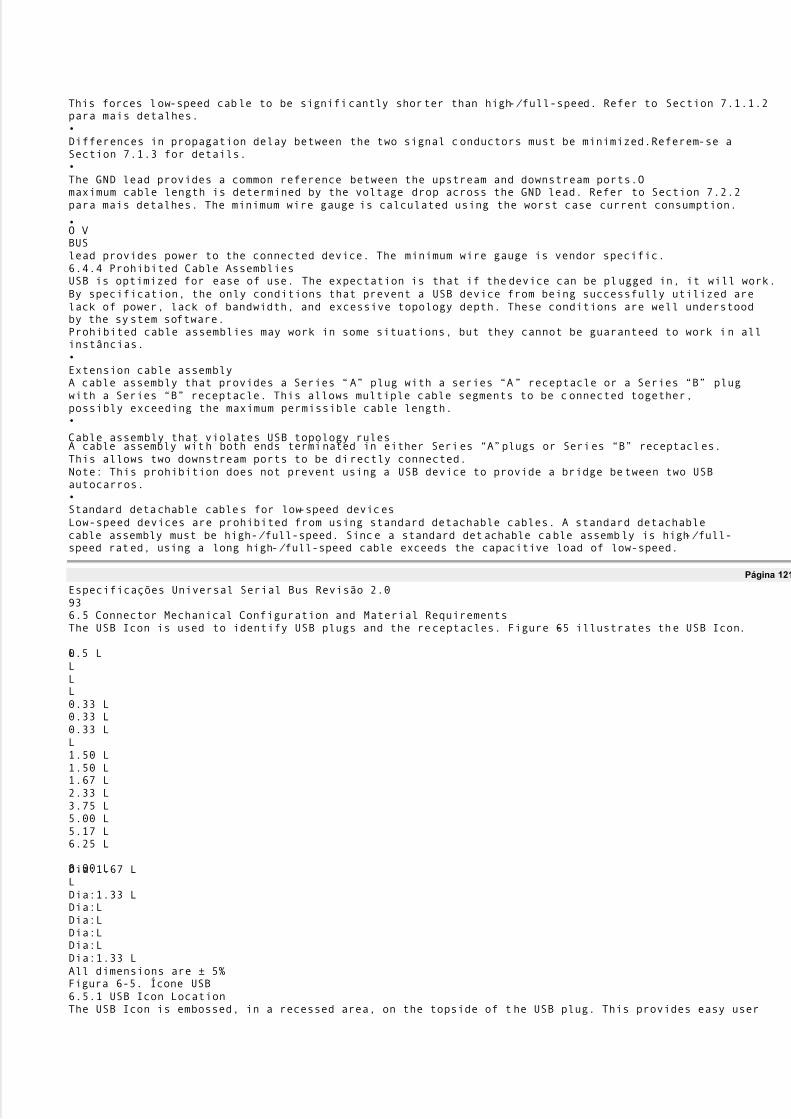
5/8/2018 Versão traduzida de USB Protocolo completo - slidepdf.com
http://slidepdf.com/reader/full/versao-traduzida-de-usb-protocolo-completo 100/112
This forces low-speed cable to be significantly shorter than high-/ full-speed. Refer to Section 7.1.1.2para mais detalhes.�Differences in propagation delay between the two signal conductors must be minimized.Referem-se aSection 7.1.3 for details.�The GND lead provides a common reference between the upstream and downstream ports.Omaximum cable length is determined by the voltage drop across the GND lead. Refer to Section 7.2.2para mais detalhes. The minimum wire gauge is calculated using the worst case current consumption.
�O VBUSlead provides power to the connected device. The minimum wire gauge is vendor specific.6.4.4 Prohibited Cable AssembliesUSB is optimized for ease of use. The expectation is that if the device can be plugged in, it will work.By specification, the only conditions that prevent a USB device from being successfully utilized arelack of power, lack of bandwidth, and excessive topology depth. These conditions are well understoodby the system software.Prohibited cable assemblies may work in some situations, but they cannot be guaranteed to work in allinstâncias.�Extension cable assemblyA cable assembly that provides a Series ´Aµ plug with a series ´Aµ receptacle or a Series ´Bµ plugwith a Series ´Bµ receptacle. This allows multiple cable segments to be connected together,possibly exceeding the maximum permissible cable length.�
Cable assembly that violates USB topology rulesA cable assembly with both ends terminated in either Series ´Aµ plugs or Series ´Bµ receptacles.This allows two downstream ports to be directly connected.Note: This prohibition does not prevent using a USB device to provide a bridge between two USBautocarros.�Standard detachable cables for low-speed devicesLow-speed devices are prohibited from using standard detachable cables. A standard detachablecable assembly must be high-/ full-speed. Since a standard detachable cable assembly is high-/ full-speed rated, using a long high-/ full-speed cable exceeds the capacitive load of low-speed.
Página 121
Especificações Universal Serial Bus Revisão 2.0936.5 Connector Mechanical Configuration and Material RequirementsThe USB Icon is used to identify USB plugs and the receptacles. Figure 6-5 illustrates the USB Icon.
L0.5 LLLL0.33 L0.33 L0.33 LL1.50 L1.50 L1.67 L2.33 L3.75 L5.00 L5.17 L6.25 L
8.00 LDia:1.67 LLDia:1.33 LDia:LDia:LDia:LDia:LDia:1.33 LAll dimensions are ± 5%Figura 6-5. Ícone USB6.5.1 USB Icon LocationThe USB Icon is embossed, in a recessed area, on the topside of the USB plug. This provides easy user

5/8/2018 Versão traduzida de USB Protocolo completo - slidepdf.com
http://slidepdf.com/reader/full/versao-traduzida-de-usb-protocolo-completo 101/112
recognition and facilitates alignment during the mating process. The USB Icon and Manufacturer's logoshould not project beyond the overmold surface. The USB Icon is required, while the Manufacturer's logois recommended, for both Series ´Aµ and ´Bµ plug assemblies. The USB Icon is also located adjacent toeach receptacle. Receptacles should be oriented to allow the Icon on the plug to be visible during themating process. Figure 6-6 illustrates the typical plug orientation.Manufacturer·sEngraved LogoAA
Ver TopOptional Top"Locator Detail"Optional Top"Locator Detail"LocalizadorAlturaAproximadamente0,6 milímetros(0.024")Locator WidthAproximadamente0,5 milímetros(0.020")432
1Engraved USBÍconeSection A - A(Plug Cross-Section)Overmolding0.6mm (0.024") MaxManufacturer·sLogotipoEngraving Recess0.6mm (0.024")MaxÍcone USBEngraving RecessFigura 6-6. Orientação plug USB típico
Página 122
Especificações Universal Serial Bus Revisão 2.0946.5.2 USB Connector Termination DataTable 6-1 provides the standardized contact terminating assignments by number and electrical value forSeries ´Aµ and Series ´Bµ connectors.Tabela 6-1. USB Connector Termination AssignmentContatoNúmeroNome de sinalTypical WiringAtribuição1VBUSVermelho2D-
Branco3D +Verde4GNDPretoConchaEscudoFio dreno6.5.3 Series ´Aµ and Series ´Bµ ReceptaclesElectrical and mechanical interface configuration data for Series "A" and Series "B" receptacles are shownin Figure 6-7 and Figure 6-8. Also, refer to Figure 6-12, Figure 6-13, and Figure 6-14 at the end of this

5/8/2018 Versão traduzida de USB Protocolo completo - slidepdf.com
http://slidepdf.com/reader/full/versao-traduzida-de-usb-protocolo-completo 102/112
chapter for typical PCB receptacle layouts.
Página 123
Especificações Universal Serial Bus Revisão 2.095Overmold Boot2.67 MINFully Mated Series "A"Receptacle and PlugReceptacle Flange1USB Series "A" Receptacle and PlugMating Features1Allow a minimum spacing of 2.67mm betweenthe face of the receptacle and the plugovermold boot.8.0 MAXSCALE: N/ AInterface and Mating DrawingSeries "A" ReceptacleTAMANHODRAWING NUMBERREVAN / ADATA2/ 98CFOLHA1 de 1HGFE
DCBA87654321HGFED
CBA876543210.38 ± 0.138.38 ± 0.08

5/8/2018 Versão traduzida de USB Protocolo completo - slidepdf.com
http://slidepdf.com/reader/full/versao-traduzida-de-usb-protocolo-completo 103/112
8.88 ± 0.204.98 ± 0.25Ponto de Contacto300± 20(2)0.50 ± 0.10
4.13 REFCenter Line of 5.12Receptacle ContactPlaca de Circuito Impresso300± 20(2)0.50 ± 0.10 (2)B Center LineC12341.84 ± 0.05
12.50 ± 0.1011.10 ± 0.10R 0.64 ± 0.13 (Typical)0.64 ± 0.13 (8)5.12 ± 0.101.00 ± 0.05 (4)R 0.32 ± 0.13 (Typical)BC Center Line3.50 ± 0.05 (2)1.00 ± 0.05 (2)AUSB Series "A" Receptacle InterfaceAll dimensions are in millimeters ( mm ) unlessem contrário.Figura 6-7. USB Series "A" Receptacle Interface and Mating Drawing
Página 124
Especificações Universal Serial Bus Revisão 2.096SCALE: N/ AInterface and Mating DrawingUSB Series "B" ReceptacleTAMANHODRAWING NUMBERREVAN / ADATA2/ 98CSHEET 1 of 1H
GFEDCBA876543

5/8/2018 Versão traduzida de USB Protocolo completo - slidepdf.com
http://slidepdf.com/reader/full/versao-traduzida-de-usb-protocolo-completo 104/112
21HGFEDCB
A87654321C Center Line300+ 20(4)8.38 + 0.080.38 + 0.13 (4)
8.45 + 0.105.60 + 0.101.00 + 0.05 (4)1.25 + 0.10 (4)1243A8.88 + 0.203.18 + 0.05BC7.78 + 0.10450+ 0.5
0(2)R 0.38 (6)3.67 + 0.080.80 + 0.081.63 + 0.05 (2)B Center LinePonto de Contacto4.98 + 0.25Receptacle ContactB Center Line300+ 20(2)Receptacle Housing
0.50 + 0.10 (2)3.67 Center LineReceptacle ShellReceptacle ShellFully Mated Plug and Receptacle2.67 MINOvermoldB

5/8/2018 Versão traduzida de USB Protocolo completo - slidepdf.com
http://slidepdf.com/reader/full/versao-traduzida-de-usb-protocolo-completo 105/112
ootOvermold
BootUSB Series "B" Receptacle and Plug Mating Features10.5 MAX11.5 MAXUSB Series "B" Receptacle Interface11Allow a minimum spacing of 2.67mm between theface of the receptacle and the plug overmold boot.All dimensions are in millimeters ( mm )salvo indicação em contrário.Figura 6-8. USB Series "B" Receptacle Interface and Mating Drawing
Página 125
Especificações Universal Serial Bus Revisão 2.0976.5.3.1 Receptacle Injection Molded Thermoplastic Insulator MaterialMinimum UL 94-V0 rated, thirty percent (30%) glass-filled polybutylene terephthalate (PBT) orpolyethylene terephthalate (PET) or better.Typical Colors: Black, gray, and natural.Flammability Characteristics: UL 94-V0 rated.Flame Retardant Package must meet or exceed the requirements for UL, CSA, VDE, etc.Oxygen Index (LOI): Greater than 21%. ASTM D 2863.6.5.3.2 Receptacle Shell MaterialsSubstrate Material: 0.30 + 0.05 mm phosphor bronze, nickel silver, or other copper based high strengthmateriais.Plating:1. Underplate: Optional. Minimum 1.00 micrometers (40 microinches) nickel. Além disso,manufacturer may use a copper underplate beneath the nickel.2. Outside: Minimum 2.5 micrometers (100 microinches) bright tin or bright tin-lead.
6.5.3.3 Receptacle Contact MaterialsSubstrate Material: 0.30 + 0.05 mm minimum half-hard phosphor bronze or other high strength copperbased material.Plating: Contacts are to be selectively plated.A. Option I1. Underplate: Minimum 1.25 micrometers (50 microinches) nickel. Copper over base materialé opcional.2. Mating Area: Minimum 0.05 micrometers (2 microinches) gold over a minimum of0.70 micrometers (28 microinches) palladium.3. Solder Tails: Minimum 3.8 micrometers (150 microinches) bright tin-lead over theunderplate.B. Option II1. Underplate: Minimum 1.25 micrometers (50 microinches) nickel. Copper over base materialé opcional.2. Mating Area: Minimum 0.05 micrometers (2 microinches) gold over a minimum of0.75 micrometers (30 microinches) palladium-nickel.3. Solder Tails: Minimum 3.8 micrometers (150 microinches) bright tin-lead over the
underplate.C. Option III1. Underplate: Minimum 1.25 micrometers (50 microinches) nickel. Copper over base materialé opcional.2. Mating Area: Minimum 0.75 micrometers (30 microinches) gold.3. Solder Tails: Minimum 3.8 micrometers (150 microinches) bright tin-lead over theunderplate.
Página 126
Especificações Universal Serial Bus Revisão 2.0986.5.4 Series ´Aµ and Series ´Bµ PlugsElectrical and mechanical interface configuration data for Series "A" and Series"B" plugs are shown in

5/8/2018 Versão traduzida de USB Protocolo completo - slidepdf.com
http://slidepdf.com/reader/full/versao-traduzida-de-usb-protocolo-completo 106/112
Figure 6-9 and Figure 6-10.
Página 127
Especificações Universal Serial Bus Revisão 2.099SCALE: N/ AInterface DrawingUSB Series "A" PlugTAMANHODRAWING NUMBERREVAN / ADATA2/ 98CSHEET 1 of 1HGFEDCBA87654321HGFEDCBA8
76543212.00 ± 0.05 (2)A1.00 ± 0.05 (4)4321BB11.75 MIN
300± 204.50 ± 0.100.15 ± 0.10 Typical300± 20Típico1.95 ± 0.0512.00 ± 0.10

5/8/2018 Versão traduzida de USB Protocolo completo - slidepdf.com
http://slidepdf.com/reader/full/versao-traduzida-de-usb-protocolo-completo 107/112
0.315 ± 0.03 Typical8.0 MAX16.0 MAX8.0 MAX4.0 MAXAA0.38 ± 0.132.50 ± 0.05 (2)
2.50 ± 0.13 (4)Plug ContactB111.75 MIN2.00 ± 0.13 (4)5.16 ± 0.10B Center LineB Center LineUL 94-V0 Plug HousingR 0.64 + 0.13 TypicalOvermold
Boot1Overall connector and cable assemblylength is measured from Datum 'A' ofthe Series "A" Plug to Datum 'A' of theSeries "B" Plug or to the blunt endrescisão.8.65 ± 0.197.41 ± 0.314.2 MINGOLD PLATE AREA3.5 ± 0.05 (2)1.0 ± 0.05 (2)6.41 ± 0.319.70 ± 0.13
Section A - AOvermold Boot0.13 ± 0.130.16 ± 0.15Section B - BAll dimensions are in millimeters ( mm )salvo indicação em contrário.Figura 6-9. USB Series "A" Plug Interface Drawing
Página 128
Especificações Universal Serial Bus Revisão 2.0100Section B - B0.80 ± 0.05AA
1.46 ± 0.10SCALE: N/ AInterface DrawingUSB Series "B" PlugTAMANHODRAWING NUMBERREVAN / ADATA2/ 98CSHEET 1 of 1

5/8/2018 Versão traduzida de USB Protocolo completo - slidepdf.com
http://slidepdf.com/reader/full/versao-traduzida-de-usb-protocolo-completo 108/112
HGFEDCBA8
7654321HGFEDCBA87
6543218.00 ± 0.105.83 ± 0.100.38 MAXC450± 0,50(2)2.85 ± 0.13 (2)7.26 ± 0.10
Center Lineof 2.853.29 ± 0.05B300± 20Típico300± 20(2)B Center LineC Center Line1
2343.70 ± 0.1311.75 MINA1BB1Overall connector and cable assembly lengthis measured from Datum 'A' of the Series "B"Plug to Datum 'A' of the Series "A" Plug or

5/8/2018 Versão traduzida de USB Protocolo completo - slidepdf.com
http://slidepdf.com/reader/full/versao-traduzida-de-usb-protocolo-completo 109/112
the blunt end termination.C Center LineSection A - A4.67 ± 0.108.65 ± 0.197.41 ± 0.316.41 ± 0.311.25 ± 0.10 (4)4.20 MIN
Gold Plate Area1.16 MAX0.13 ± 0.13Típico0.16 ± 0.15Típico10.5 MAXOvermold BootOvermold Boot11.5 MAX
All dimensions are in millimeters ( mm )salvo indicação em contrário.0.25 ± 0.05Figura 6-10. USB Series ´Bµ Plug Interface Drawing
Página 129
Especificações Universal Serial Bus Revisão 2.01016.5.4.1 Plug Injection Molded Thermoplastic Insulator MaterialMinimum UL 94-V0 rated, thirty percent (30%) glass-filled polybutylene terephthalate (PBT) orpolyethylene terephthalate (PET) or better.Typical Colors: Black, gray, and natural.Flammability Characteristics: UL 94-V0 rated.Flame Retardant Package must meet or exceed the requirements for UL, CSA, and VDE.Oxygen Index (LOI): 21%. ASTM D 2863.6.5.4.2 Plug Shell Materials
Substrate Material: 0.30 + 0.05 mm phosphor bronze, nickel silver, or other suitable material.Plating:A. Underplate: Optional. Minimum 1.00 micrometers (40 microinches) nickel. Além disso,manufacturer may use a copper underplate beneath the nickel.B. Outside: Minimum 2.5 micrometers (100 microinches) bright tin or bright tin-lead.6.5.4.3 Plug (Male) Contact MaterialsSubstrate Material: 0.30 + 0.05 mm half-hard phosphor bronze.Plating: Contacts are to be selectively plated.A. Option I1. Underplate: Minimum 1.25 micrometers (50 microinches) nickel. Copper over base materialé opcional.2. Mating Area: Minimum 0.05 micrometers (2 microinches) gold over a minimum of0.70 micrometers (28 microinches) palladium.3. Solder Tails: Minimum 3.8 micrometers (150 microinches) bright tin-lead over theunderplate.B. Option II1. Underplate: Minimum 1.25 micrometers (50 microinches) nickel. Copper over base material
é opcional.2. Mating Area: Minimum 0.05 micrometers (2 microinches) gold over a minimum of0.75 micrometers (30 microinches) palladium-nickel.3. Wire Crimp/ Solder Tails: Minimum 3.8 micrometers (150 microinches) bright tin-lead overthe underplate.C. Option III1. Underplate: Minimum 1.25 micrometers (50 microinches) nickel. Copper over base materialé opcional.2. Mating Area: Minimum 0.75 micrometers (30 microinches) gold.3. Solder Tails: Minimum 3.8 micrometers (150 microinches) bright tin-lead over theunderplate.
Página 130

5/8/2018 Versão traduzida de USB Protocolo completo - slidepdf.com
http://slidepdf.com/reader/full/versao-traduzida-de-usb-protocolo-completo 110/112
Especificações Universal Serial Bus Revisão 2.01026.6 Cable Mechanical Configuration and Material RequirementsHigh-/ full-speed and low-speed cables differ in data conductor arrangement and shielding. Baixa velocidaderecommends, but does not require, use of a cable with twisted data conductors. Low speed recommends,but does not require, use of a cable with a braided outer shield. Figure 6-11 shows the typical high-/ full-speed cable construction.B
RGWPolyvinyl Chloride (PVC) JacketOuter Shield > 65% InterwovenTinned Copper BraidInner Shield AluminumMetallized Polyester28 AWG TinnedCopper Drain WireTwisted Signaling Pair:Branco:D-Verde:D +on-Twisted Power Pair:Vermelho:
VBUSBlack: Power GroundFigura 6-11. Typical High-/ full-speed Cable Construction6.6.1 DescriptionHigh-/ full-speed cable consists of one 28 to 20 AWG non-twisted power pair and one 28 AWG twisted datapair with an aluminum metallized polyester inner shield, 28 AWG stranded tinnedcopper drain wire,> 65% tinned copper wire interwoven (braided) outer shield, and PVC outer jacket.Low-speed cable consists of one 28 to 20 AWG non-twisted power pair and one 28 AWG data pair (a twistis recommended) with an aluminum metallized polyester inner shield, 28 AWG stranded tinned copperdrain wire and PVC outer jacket. A > 65% tinned copper wire interwoven (braided) outer shield isrecomendado.
Página 131
Especificações Universal Serial Bus Revisão 2.0103
6.6.2 ConstructionRaw materials used in the fabrication of this cable must be of such quality that the fabricated cable iscapable of meeting or exceeding the mechanical and electrical performance criteria of the most currentUSB Specification revision and all applicable domestic and international safety/ testing agencyrequirements; eg, UL, CSA, BSA, NEC, etc., for electronic signaling and power distribution cables in itscategoria.Tabela 6-2. Power PairAmerican WireGauge (AWG)Nominal ConductorOuter DiameterStranded TinnedCondutores280.381 mm (0.015µ)0.406 mm (0.016µ)7 x 36
19 x 40260.483 mm (0.019µ)0.508 mm (0.020µ)7 x 3419 x 38240.610 mm (0.024µ)0.610 mm (0.024µ)7 x 3219 x 36220.762 mm (0.030µ)
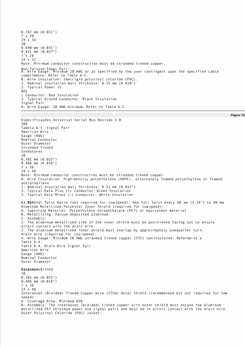
5/8/2018 Versão traduzida de USB Protocolo completo - slidepdf.com
http://slidepdf.com/reader/full/versao-traduzida-de-usb-protocolo-completo 111/112
0.787 mm (0.031µ)7 x 3019 x 34200.890 mm (0.035µ)0.931 mm (0.037µ)7 x 2819 x 32Note: Minimum conductor construction must be stranded tinned copper.
Non-Twisted Power Pair:A. Wire Gauge: Minimum 28 AWG or as specified by the user contingent upon the specified cablecomprimento. Refer to Table 6-2.B. Wire Insulation: Semirigid polyvinyl chloride (PVC).1. Nominal Insulation Wall Thickness: 0.25 mm (0.010µ)2. Typical Power (VBUS) Conductor: Red Insulation3. Typical Ground Conductor: Black InsulationSignal Pair:A. Wire Gauge: 28 AWG minimum. Refer to Table 6-3.
Página 132
Especificações Universal Serial Bus Revisão 2.0104Tabela 6-3. Signal PairAmerican WireGauge (AWG)Nominal ConductorOuter DiameterStranded TinnedCondutores280.381 mm (0.015µ)0.406 mm (0.016µ)7 x 3619 x 40Note: Minimum conductor construction must be stranded tinned copper.B. Wire Insulation: High-density polyethylene (HDPE), alternately foamed polyethylene or foamedpolipropileno1. Nominal Insulation Wall Thickness: 0.31 mm (0.012µ)2. Typical Data Plus (+) Conductor: Green Insulation3. Typical Data Minus (-) Conductor: White Insulation
C. Nominal Twist Ratio (not required for low-speed): One full twist every 60 mm (2.36µ) to 80 mm(3.15µ)Aluminum Metallized Polyester Inner Shield (required for low-speed):A. Substrate Material: Polyethylene terephthalate (PET) or equivalent materialB. Metallizing: Vacuum deposited aluminumC. Assembly:1. The aluminum metallized side of the inner shield must be positioned facing out to ensuredirect contact with the drain wire.2. The aluminum metallized inner shield must overlap by approximately one-quarter turn.Drain Wire (required for low-speed):A. Wire Gauge: Minimum 28 AWG stranded tinned copper (STC) non-insulated. Referem-se aTable 6-4.Table 6-4. Drain Wire Signal PairAmerican WireGauge (AWG)Nominal ConductorOuter Diameter
Stranded TinnedCondutores280.381 mm (0.015µ)0.406 mm (0.016µ)7 x 3619 x 40Interwoven (Braided) Tinned Copper Wire (ITCW) Outer Shield (recommended but not required for low-speed):A. Coverage Area: Minimum 65%.B. Assembly: The interwoven (braided) tinned copper wire outer shield must encase the aluminummetallized PET shielded power and signal pairs and must be in direct contact with the drain wire.Outer Polyvinyl Chloride (PVC) Jacket:

5/8/2018 Versão traduzida de USB Protocolo completo - slidepdf.com
http://slidepdf.com/reader/full/versao-traduzida-de-usb-protocolo-completo 112/112
A. Assembly: The outer PVC jacket must encase the fully shielded power and signal pairs and mustbe in direct contact with the tinned copper outer shield.
Página 133
Especificações Universal Serial Bus Revisão 2.0105B. Nominal Wall Thickness: 0.64 mm (0.025µ).Marking: The cable must be legibly marked using contrasting color permanent ink.A. Minimum marking information for high-/ full-speed cable must include:USB SHIELDED <Gauge/ 2C + Gauge/ 2C> UL CM 75oC ³ UL Vendor ID.B. Minimum marking information for low-speed cable shall include:USB specific marking is not required for low-speed cable.Nominal Fabricated Cable Outer Diameter:This is a nominal value and may vary slightly from manufacturer to manufacturer as a function of theconductor insulating materials and conductor specified. Refer to Table 6-5.Table 6-5. Nominal Cable DiameterShielded USBCabo de configuraçãoNominal OuterCable Diameter28/ 284.06 mm (0.160µ)28/ 264.32 mm (0.170µ)28/ 244.57 mm (0.180µ)28/ 224.83 mm (0.190µ)28/ 205.21 mm (0.205µ)6.6.3 Electrical CharacteristicsAll electrical characteristics must be measured at or referenced to +20oC (68oF).Voltage Rating: 30 V rms maximum.Conductor Resistance: Conductor resistance must be measured in accordance withASTM-D-4566Seção 13. Refer to Table 6-6.Conductor Resistance Unbalance (Pairs): Conductor resistance unbalance between two (2) conductors of
any pair must not exceed five percent (5%) when measured in accordance with ASTM-D-4566 Section 15.The DC resistance from plug shell to plug shell (or end of integrated cable) must be less than 0.6 ohms.Table 6-6. Conductor ResistanceAmericanoWire Gauge (AWG)Ohms ( ) / 100 MetersMáximo2823,202614,60249,09225,74203,58
Page 134
Especificações Universal Serial Bus Revisão 2.01066.6.4 Cable Environmental CharacteristicsFaixa de temperatura:A. Operating Temperature Range: 0oC a +50o