


Línguas
Páginas
Legal

ControlNet™ Adapter Module(Catalog Numbers 1747-ACN15, 1747-ACNR15)
User Manual
Important User Information Because of the variety of uses for the products described in this publication, those responsible for the application and use of this control equipment must satisfy themselves that all necessary steps have been taken to assure that each application and use meets all performance and safety requirements, including any applicable laws, regulations, codes and standards.
The illustrations, charts, sample programs and layout examples shown in this guide are intended solely for purposes of example. Since there are many variables and requirements associated with any particular installation, Allen-Bradley does not assume responsibility or liability (to include intellectual property liability) for actual use based upon the examples shown in this publication.
Allen-Bradley publication SGI-1.1, Safety Guidelines for the Application, Installation and Maintenance of Solid-State Control (available from your local Allen-Bradley office), describes some important differences between solid-state equipment and electromechanical devices that should be taken into consideration when applying products such as those described in this publication.
Reproduction of the contents of this copyrighted publication, in whole or part, without written permission of Rockwell Automation, is prohibited.
Throughout this manual we use notes to make you aware of safety considerations:
Attention statements help you to:
• identify a hazard
• avoid a hazard
• recognize the consequences
ControlNet and SLC 500 are trademarks of Rockwell Automation.
PLC-5 is a registered trademark of Rockwell Automation.
ATTENTION
!!!!Identifies information about practices or circumstances that can lead to personal injury or death, property damage or economic loss
IMPORTANT Identifies information that is critical for successful application and understanding of the product.
Table of Contents
Preface Who Should Use this Manual . . . . . . . . . . . . . . . . . . . . . . . . . . . . . P-1Purpose of this Manual . . . . . . . . . . . . . . . . . . . . . . . . . . . . . . . . . . P-1
Related Documentation . . . . . . . . . . . . . . . . . . . . . . . . . . . . . . P-1Common Techniques Used in this Manual. . . . . . . . . . . . . . . . . . . P-1Rockwell Automation Support . . . . . . . . . . . . . . . . . . . . . . . . . . . . P-2
Local Product Support . . . . . . . . . . . . . . . . . . . . . . . . . . . . . . . P-2Technical Product Assistance. . . . . . . . . . . . . . . . . . . . . . . . . . . P-2Your Questions or Comments on this Manual . . . . . . . . . . . . . P-2
Chapter 1Introducing the ControlNet Adapter Module
Chapter Objectives . . . . . . . . . . . . . . . . . . . . . . . . . . . . . . . . . . . . . 1-1Module Description and Features . . . . . . . . . . . . . . . . . . . . . . . . . . 1-1Hardware Components . . . . . . . . . . . . . . . . . . . . . . . . . . . . . . . . . . 1-1
Diagnostic Indicators . . . . . . . . . . . . . . . . . . . . . . . . . . . . . . . . 1-2Network Access Port (NAP) . . . . . . . . . . . . . . . . . . . . . . . . . . . 1-2ControlNet Connectors . . . . . . . . . . . . . . . . . . . . . . . . . . . . . . 1-3Network Address Switch Assemblies . . . . . . . . . . . . . . . . . . . . . 1-3
Chapter 2Installing Your ControlNet Adapter Module
Chapter Objectives . . . . . . . . . . . . . . . . . . . . . . . . . . . . . . . . . . . . . 2-1Compliance to European Union Directives . . . . . . . . . . . . . . . . . . . 2-1
EMC Directive . . . . . . . . . . . . . . . . . . . . . . . . . . . . . . . . . . . . . 2-1Low Voltage Directive. . . . . . . . . . . . . . . . . . . . . . . . . . . . . . . . 2-2
Determining Power Requirements . . . . . . . . . . . . . . . . . . . . . . . . . 2-2Setting the Network Address Switches. . . . . . . . . . . . . . . . . . . . . . . 2-2Installing the Adapter Module in the Chassis . . . . . . . . . . . . . . . . . 2-3
Connecting Your Adapter to the ControlNet Network . . . . . . . 2-4Connecting Programming Terminals to the Network via the NAP . 2-6Powerup Sequence . . . . . . . . . . . . . . . . . . . . . . . . . . . . . . . . . . . . . 2-7
Chapter 3Planning to Use Your ControlNet Adapter Module
Chapter Objectives . . . . . . . . . . . . . . . . . . . . . . . . . . . . . . . . . . . . . 3-1Compatible 1746 and 1747 I/O Modules . . . . . . . . . . . . . . . . . . . . 3-1Overview of Adapter Operation . . . . . . . . . . . . . . . . . . . . . . . . . . . 3-2
Software Requirements . . . . . . . . . . . . . . . . . . . . . . . . . . . . . . . 3-2Rack and Module Connections . . . . . . . . . . . . . . . . . . . . . . . . . 3-3Optimizing SLC ControlNet Adapter Rack Connections . . . . . 3-4Module Keying . . . . . . . . . . . . . . . . . . . . . . . . . . . . . . . . . . . . . 3-5Output Operation During Fault and Idle Modes . . . . . . . . . . . 3-6
Understanding ControlNet I/O . . . . . . . . . . . . . . . . . . . . . . . . . . . 3-6Scheduled Data-Transfer Connections on a ControlNet Network. . . . . . . . . . . . . . . . . . . . . . . . . . . . . . . . . 3-6
i Publication 1747-UM003A-EN-P
Table of Contents ii
Chapter 4Application Examples Example 1 . . . . . . . . . . . . . . . . . . . . . . . . . . . . . . . . . . . . . . . . . . . . 4-2
Hardware Setup . . . . . . . . . . . . . . . . . . . . . . . . . . . . . . . . . . . . 4-2Configuring The ControlNet Network with RSNetWorx™ for ControlNet . . . . . . . . . . . . . . . . . . . . . . . . . 4-3Create a Ladder Logic Program . . . . . . . . . . . . . . . . . . . . . . . . 4-10
Example 2 . . . . . . . . . . . . . . . . . . . . . . . . . . . . . . . . . . . . . . . . . . . 4-11Hardware Setup . . . . . . . . . . . . . . . . . . . . . . . . . . . . . . . . . . . 4-11Configuring The ControlNet Network with RSNetWorx™ for ControlNet . . . . . . . . . . . . . . . . . . . . . . . . 4-12Create a Ladder Program. . . . . . . . . . . . . . . . . . . . . . . . . . . . . 4-20
Example 3 . . . . . . . . . . . . . . . . . . . . . . . . . . . . . . . . . . . . . . . . . . . 4-21Hardware Setup . . . . . . . . . . . . . . . . . . . . . . . . . . . . . . . . . . . 4-21Configuring The ControlNet Network with RSNetWorx™ for ControlNet . . . . . . . . . . . . . . . . . . . . . . . . 4-22Create a Ladder Logic Program . . . . . . . . . . . . . . . . . . . . . . . . 4-30
Example 4 . . . . . . . . . . . . . . . . . . . . . . . . . . . . . . . . . . . . . . . . . . . 4-31Hardware Setup . . . . . . . . . . . . . . . . . . . . . . . . . . . . . . . . . . . 4-31Configuring The ControlNet Network with RSNetWorx™ for ControlNet . . . . . . . . . . . . . . . . . . . . . . . . 4-32Create Ladder Logic and Basic Module Programs . . . . . . . . . . 4-43
Example 5 . . . . . . . . . . . . . . . . . . . . . . . . . . . . . . . . . . . . . . . . . . . 4-46Hardware Setup . . . . . . . . . . . . . . . . . . . . . . . . . . . . . . . . . . . 4-46Configuring The ControlNet Network with RSNetWorx for ControlNet . . . . . . . . . . . . . . . . . . . . . . . . . . 4-47Create a Ladder Logic Program . . . . . . . . . . . . . . . . . . . . . . . . 4-57
Chapter 5Troubleshooting Chapter Objectives . . . . . . . . . . . . . . . . . . . . . . . . . . . . . . . . . . . . . 5-1
Troubleshooting With the Status Indicators and Status Display . . . 5-1Health Indicators and Display Mnemonics . . . . . . . . . . . . . . . . 5-2
ControlNet Status Indicators . . . . . . . . . . . . . . . . . . . . . . . . . . . . . 5-3
Appendix ASpecifications
Appendix BUnderstanding Your SLC 500/1746 Control System
Selecting Your SLC 500/1746 Control Power Supply . . . . . . . . . . . B-1Power Supply Specifications . . . . . . . . . . . . . . . . . . . . . . . . . . . B-2
SLC 500 System Installation Recommendations . . . . . . . . . . . . . . . B-6Typical Installation . . . . . . . . . . . . . . . . . . . . . . . . . . . . . . . . . . B-6Selecting an Enclosure. . . . . . . . . . . . . . . . . . . . . . . . . . . . . . . . B-6Spacing Considerations . . . . . . . . . . . . . . . . . . . . . . . . . . . . . . . B-7Preventing Excessive Heat . . . . . . . . . . . . . . . . . . . . . . . . . . . . . B-8Wiring Layout. . . . . . . . . . . . . . . . . . . . . . . . . . . . . . . . . . . . . . B-8
Publication 1747-UM003A-EN-P
Table of Contents iii
Grounding Guidelines. . . . . . . . . . . . . . . . . . . . . . . . . . . . . . . . B-9Master Control Relay . . . . . . . . . . . . . . . . . . . . . . . . . . . . . . . B-11Emergency-Stop Switches . . . . . . . . . . . . . . . . . . . . . . . . . . . . B-13Common Power Source . . . . . . . . . . . . . . . . . . . . . . . . . . . . . B-15Loss of Power Source. . . . . . . . . . . . . . . . . . . . . . . . . . . . . . . . B-16Input States on Power Down . . . . . . . . . . . . . . . . . . . . . . . . . B-16Other Types of Line Conditions . . . . . . . . . . . . . . . . . . . . . . . B-16Power Conditioning Considerations . . . . . . . . . . . . . . . . . . . . B-16Special Considerations. . . . . . . . . . . . . . . . . . . . . . . . . . . . . . . B-18Output Contact Protection . . . . . . . . . . . . . . . . . . . . . . . . . . . B-20
Mounting Your Control System . . . . . . . . . . . . . . . . . . . . . . . . . . B-21Mounting Modular Hardware Style Units. . . . . . . . . . . . . . . . B-21
Installing Your I/O Module . . . . . . . . . . . . . . . . . . . . . . . . . . . . . B-25Features of an SLC 500 I/O Module . . . . . . . . . . . . . . . . . . . . B-25Definition of Sinking and Sourcing. . . . . . . . . . . . . . . . . . . . . B-26Inserting I/O Modules . . . . . . . . . . . . . . . . . . . . . . . . . . . . . . B-28Removing I/O Modules . . . . . . . . . . . . . . . . . . . . . . . . . . . . . B-30
Wiring the I/O Modules . . . . . . . . . . . . . . . . . . . . . . . . . . . . . . . . B-31Using Removable Terminal Blocks . . . . . . . . . . . . . . . . . . . . . B-32
Calculating Heat Dissipation for Your Control System. . . . . . . . . B-34Module Heat Dissipation: Calculated Watts vs. Maximum Watts . . . . . . . . . . . . . . . . . . . . . . . . . . . . . . . . B-34Calculating the Power Supply Loading . . . . . . . . . . . . . . . . . . B-35Determining the Power Supply Dissipation. . . . . . . . . . . . . . . B-38
Glossary
Index
Publication 1747-UM003A-EN-P

Table of Contents iv
Publication 1747-UM003A-EN-P

Preface
Read this preface to familiarize yourself with the rest of the manual. It provides information concerning:
• who should use this manual
• the purpose of this manual
• related documentation
• conventions used in this manual
• Allen-Bradley support
Who Should Use this Manual
Use this manual if you are responsible for designing, installing, programming, or troubleshooting control systems that use the ControlNet Adapter Module.
You should have a basic understanding of electrical circuitry and familiarity with relay logic. If you do not, obtain the proper training before using this product.
Purpose of this Manual This manual is a reference guide for the ControlNet Adapter Module. It describes the procedures you use to install, program and troubleshoot your module. This manual also includes several application examples.
Related Documentation
The following documents contain additional information concerning Allen-Bradley products. To obtain a copy, contact your local Allen-Bradley office or distributor.
Common Techniques Used in this Manual
The following conventions are used throughout this manual:
• Bulleted lists such as this one provide information, not procedural steps.
• Numbered lists provide sequential steps or hierarchical information.
• Italic type is used for emphasis.
Publication Publication Number
ControlNet PLC-5 Programmable Controllers User Manual Phase 1.5 1785-6.5.22ControlNet Cable System Component List AG-2.2ControlNet Cable System Planning and Installation Manual 1786-6.2.1ControlNet Coax Tap Installation Instructions 1786-2.3 ControlNet Network Access Cable Installation Instructions 1786-2.6ControlNet Repeater Installation Instructions 1786-2.7 Industrial Automation Wiring and Grounding Guidelines 1770-4.1SLC 500™ Modular Hardware Style User Manual 1747-6.2ControlNet Scanner Module Reference Manual 1747-6.23
1 Publication 1747-UM003A-EN-P
Preface 2
Rockwell Automation Support
Rockwell Automation offers support services worldwide, with over 75 Sales/Support Offices, 512 authorized Distributors and 260 authorized Systems Integrators located throughout the United States alone, plus Rockwell Automation representatives in every major country in the world.
Local Product Support
Contact your local Rockwell Automation representative for:
• sales and order support
• product technical training
• warranty support
• support service agreements
Technical Product Assistance
If you need to contact Rockwell Automation for technical assistance, please review the Troubleshooting appendix in your controller’s User Manual first. Then call your local Rockwell Automation representative.
Your Questions or Comments on this Manual
If you find a problem with this manual, or you have any suggestions for how this manual could be made more useful to you, please contact us at the address below:
Rockwell AutomationControl and Information GroupTechnical Communication, Dept. A602VP.O. Box 2086Milwaukee, WI 53201-2086
or visit our internet page at:
http://www.rockwellautomation.com
Publication 1747-UM003A-EN-P
Chapter 1
Introducing the ControlNet Adapter Module
Chapter Objectives This chapter describes the ControlNet adapter modules (cat. no. 1747-ACN15 and 1747-ACNR15):
• features
• hardware components, including
– diagnostic indicators
– network access port (NAP)
– ControlNet connectors
– network address switch assemblies
Module Description and Features
The 1747-ACN15 and 1747-ACNR15 adapters control remote 1746 I/O on the ControlNet network. The ControlNet network is a communication architecture that allows the exchange of messages between ControlNet products compliant with the CI specification.
The 1747-ACN15 and 1747-ACNR15 adapters features include:
• high-speed data transfer
• diagnostic messages
• local communication network access through the network access port (NAP)
• redundant media (1747-ACNR15 only)
Hardware Components The adapter module consists of the following major components:
• ControlNet status indicators
• status display
• network access port (NAP)
• ControlNet connectors (one on 1747-ACN15; two on 1747-ACNR15)
• module net address switch assemblies (on top of module)
1 Publication 1747-UM003A-EN-P
1-2 Introducing the ControlNet Adapter Module
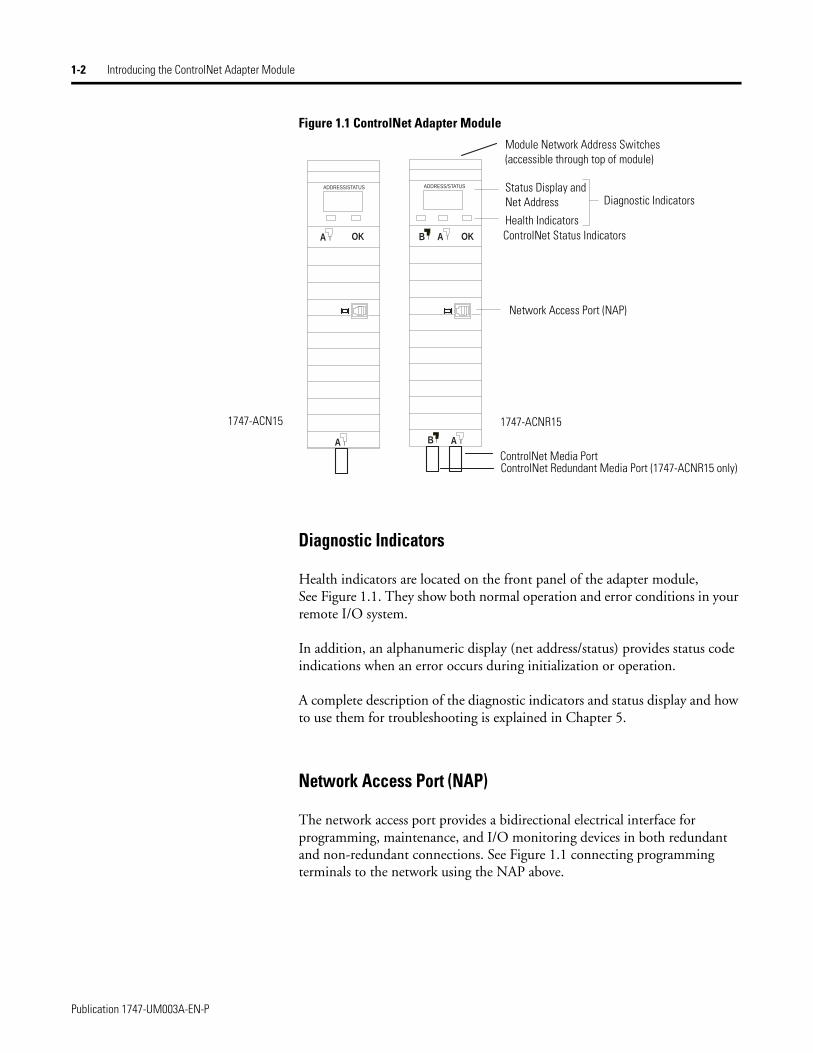
Figure 1.1 ControlNet Adapter Module
Diagnostic Indicators
Health indicators are located on the front panel of the adapter module, See Figure 1.1. They show both normal operation and error conditions in your remote I/O system.
In addition, an alphanumeric display (net address/status) provides status code indications when an error occurs during initialization or operation.
A complete description of the diagnostic indicators and status display and how to use them for troubleshooting is explained in Chapter 5.
Network Access Port (NAP)
The network access port provides a bidirectional electrical interface for programming, maintenance, and I/O monitoring devices in both redundant and non-redundant connections. See Figure 1.1 connecting programming terminals to the network using the NAP above.
ADDRESS/STATUS ADDRESS/STATUS
BA A
A AB
OK OK
Module Network Address Switches (accessible through top of module)
Status Display and Net Address
Health IndicatorsControlNet Status Indicators
Diagnostic Indicators
Network Access Port (NAP)
1747-ACNR15
ControlNet Media PortControlNet Redundant Media Port (1747-ACNR15 only)
1747-ACN15
Publication 1747-UM003A-EN-P
Introducing the ControlNet Adapter Module 1-3
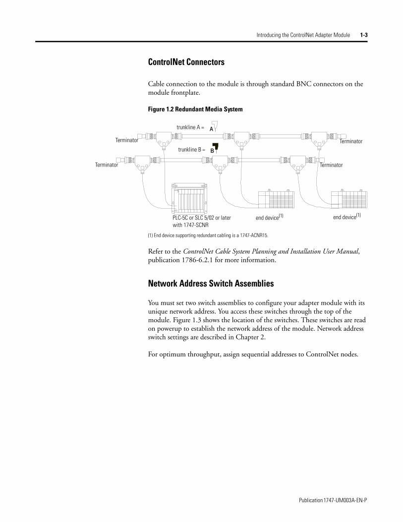
ControlNet Connectors
Cable connection to the module is through standard BNC connectors on the module frontplate.
Figure 1.2 Redundant Media System
(1) End device supporting redundant cabling is a 1747-ACNR15.
Refer to the ControlNet Cable System Planning and Installation User Manual, publication 1786-6.2.1 for more information.
Network Address Switch Assemblies
You must set two switch assemblies to configure your adapter module with its unique network address. You access these switches through the top of the module. Figure 1.3 shows the location of the switches. These switches are read on powerup to establish the network address of the module. Network address switch settings are described in Chapter 2.
For optimum throughput, assign sequential addresses to ControlNet nodes.
B
Atrunkline A =
trunkline B =
Terminator
Terminator
PLC-5C or SLC 5/02 or later with 1747-SCNR
end device(1) end device(1)
Terminator
Terminator
Publication 1747-UM003A-EN-P

1-4 Introducing the ControlNet Adapter Module
Publication 1747-UM003A-EN-P
Chapter 2
Installing Your ControlNet Adapter Module
Chapter Objectives This chapter describes the procedures for installing your ControlNet adapter module. These include:
• European Directive compliance
• determining power requirements
• setting the network address switches
• setting the I/O chassis switches
• installing the adapter module in the chassis
• connecting programming terminals to the network via the network access port (NAP)
• powerup sequence
Compliance to European Union Directives
For general installation guidelines, see SLC 500 System Installation Recommendations on page B-6. If this product has the CE mark it is approved for installation within the European Union and EEA regions. It has been designed and tested to meet the following directives.
EMC Directive
This product is tested to meet Council Directive 89/336/EEC Electromagnetic Compatibility (EMC) and the following standards, in whole or in part, documented in a technical construction file:
• EN 50081-2 EMC - Generic Emission Standard, Part 2 - Industrial Environment
• EN 50082-2 EMC - Generic Immunity Standard, Part 2 - Industrial Environment
This product is intended for use in an industrial environment.
1 Publication 1747-UM003A-EN-P
2-2 Installing Your ControlNet Adapter Module
Low Voltage Directive
This product is tested to meet Council Directive 73/23/EEC Low Voltage, by applying the safety requirements of EN 61131-2 Programmable Controllers, Part 2 - Equipment Requirements and Tests.
For specific information required by EN 61131-2, see the appropriate sections in this publication, as well as the following Allen-Bradley publications:
• Industrial Automation Wiring and Grounding Guidelines For Noise Immunity, publication 1770-4.1
• Automation Systems Catalog, publication B111
Determining Power Requirements
The ControlNet adapter module requires a maximum backplane current of 900 mA at 5V dc. Remember to add this amount to other current requirements for your I/O chassis.
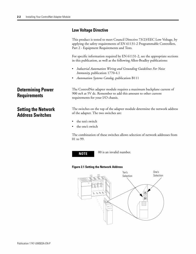
Setting the Network Address Switches
The switches on the top of the adapter module determine the network address of the adapter. The two switches are:
• the ten’s switch
• the one’s switch
The combination of these switches allows selection of network addresses from 01 to 99.
Figure 2.1 Setting the Network Address
NOTE 00 is an invalid number.
Ten’s Selection
One’s Selection
Publication 1747-UM003A-EN-P
Installing Your ControlNet Adapter Module 2-3
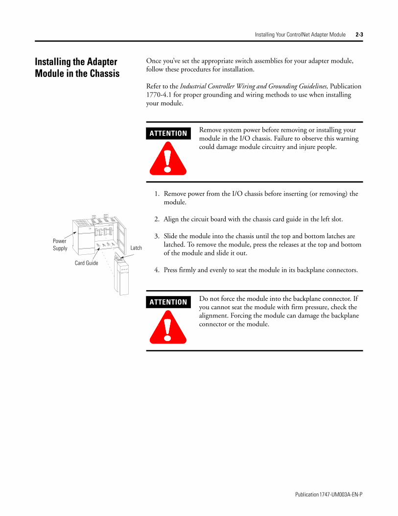
Installing the Adapter Module in the Chassis
Once you’ve set the appropriate switch assemblies for your adapter module, follow these procedures for installation.
Refer to the Industrial Controller Wiring and Grounding Guidelines, Publication 1770-4.1 for proper grounding and wiring methods to use when installing your module.
1. Remove power from the I/O chassis before inserting (or removing) the module.
2. Align the circuit board with the chassis card guide in the left slot.
3. Slide the module into the chassis until the top and bottom latches are latched. To remove the module, press the releases at the top and bottom of the module and slide it out.
4. Press firmly and evenly to seat the module in its backplane connectors.
ATTENTION
!!!!Remove system power before removing or installing your module in the I/O chassis. Failure to observe this warning could damage module circuitry and injure people.
ATTENTION
!!!!Do not force the module into the backplane connector. If you cannot seat the module with firm pressure, check the alignment. Forcing the module can damage the backplane connector or the module.
Card Guide
Power Supply Latch
Publication 1747-UM003A-EN-P

2-4 Installing Your ControlNet Adapter Module
Connecting Your Adapter to the ControlNet Network
You connect your 1747-ACN15 or -ACNR15 adapter module to a ControlNet network via taps. These taps are available:
1. Remove the tap’s dust cap (located on the straight or right angle connector).
Straight T-tap Straight Y-tap Right-angle T-tap Right-angle Y-tap
1786-TPS 1786-TPYS 1786-TPR 1786-TPYR
IMPORTANT Taps contain passive electronics and must be purchased from Allen-Bradley for the network to function properly.
If your node supports:
Connect the tap’s straight or right angle connector:
Non-redundant media to the channel A connector on the 1747-ACN15 or 1747-ACNR15 (channel B on the 1747-ACNR is not used)(1)
(1) While both channels are active, Allen-Bradley recommends using channel A for non-redundant media.
Redundant media • from trunkline A to channel A on the 1747-ACNR15• from trunkline B to channel B on the 1747-ACNR15
ATTENTION
!!!!Do not allow any metal portions of the tap to contact any conductive material. If you disconnect the tap from the adapter, place the dust cap back on the straight or right angle connector to prevent the connector from accidentally contacting a metallic grounded surface.
Publication 1747-UM003A-EN-P
Installing Your ControlNet Adapter Module 2-5
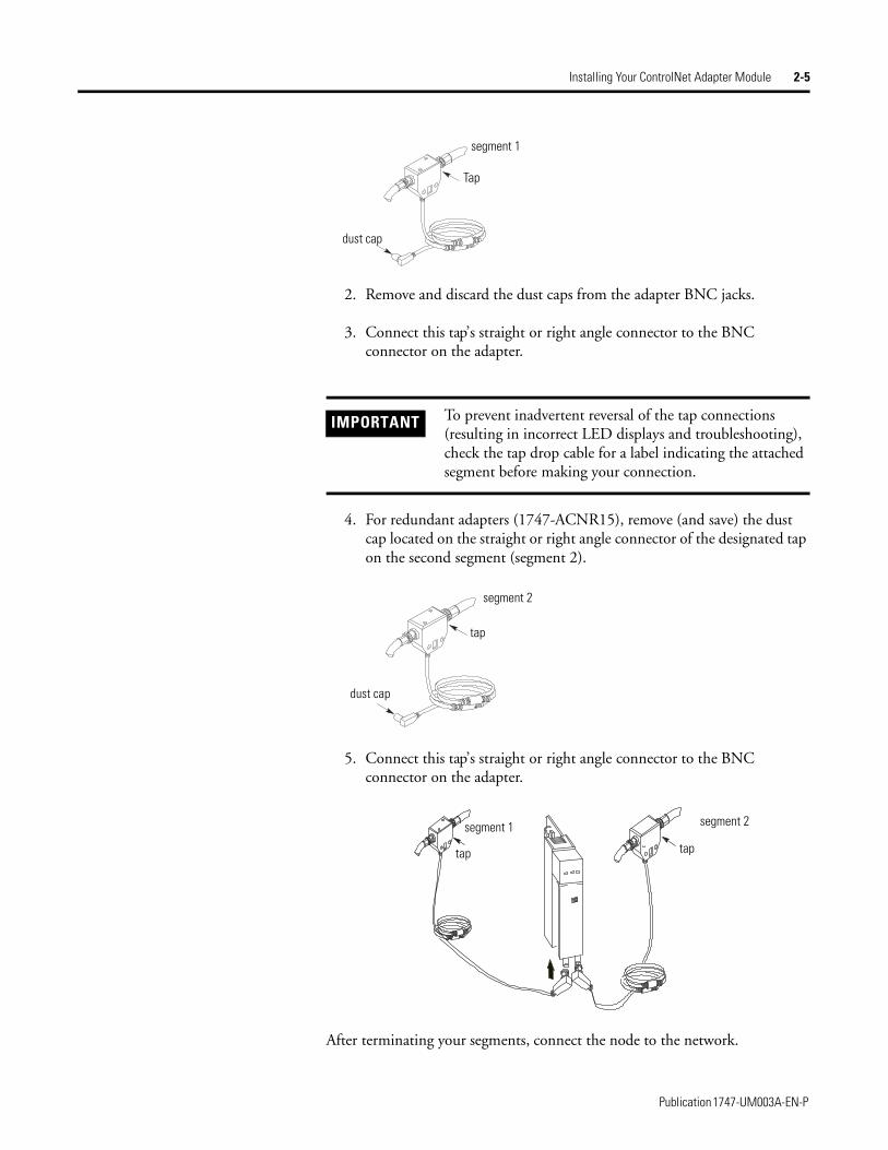
2. Remove and discard the dust caps from the adapter BNC jacks.
3. Connect this tap’s straight or right angle connector to the BNC connector on the adapter.
4. For redundant adapters (1747-ACNR15), remove (and save) the dust cap located on the straight or right angle connector of the designated tap on the second segment (segment 2).
5. Connect this tap’s straight or right angle connector to the BNC connector on the adapter.
After terminating your segments, connect the node to the network.
IMPORTANT To prevent inadvertent reversal of the tap connections (resulting in incorrect LED displays and troubleshooting), check the tap drop cable for a label indicating the attached segment before making your connection.
segment 1
Tap
dust cap
segment 2
tap
dust cap
segment 1
tap
segment 2
tap
Publication 1747-UM003A-EN-P
2-6 Installing Your ControlNet Adapter Module
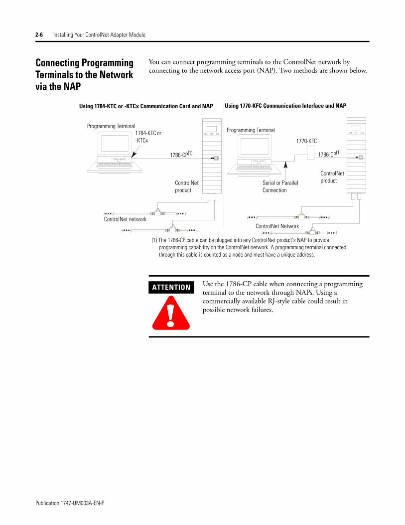
Connecting Programming Terminals to the Network via the NAP
You can connect programming terminals to the ControlNet network by connecting to the network access port (NAP). Two methods are shown below.
Using 1784-KTC or -KTCx Communication Card and NAP
Programming Terminal1784-KTC or -KTCx
1786-CP(1)
ControlNet product
ControlNet network
Using 1770-KFC Communication Interface and NAP
Programming Terminal
1770-KFC
1786-CP(1)
Serial or Parallel Connection
ControlNet product
ControlNet Network
(1) The 1786-CP cable can be plugged into any ControlNet product’s NAP to provide programming capability on the ControlNet network. A programming terminal connected through this cable is counted as a node and must have a unique address.
ATTENTION
!!!!Use the 1786-CP cable when connecting a programming terminal to the network through NAPs. Using a commercially available RJ-style cable could result in possible network failures.
Publication 1747-UM003A-EN-P
Installing Your ControlNet Adapter Module 2-7
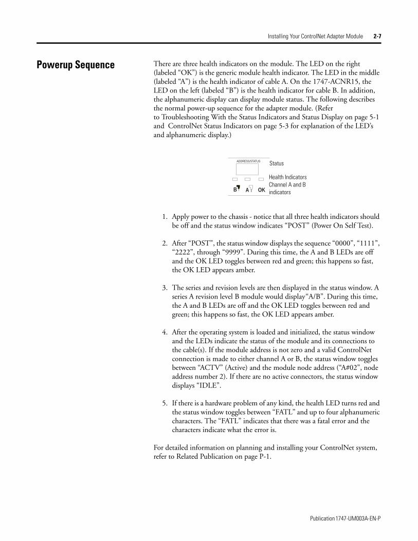
Powerup Sequence There are three health indicators on the module. The LED on the right (labeled “OK”) is the generic module health indicator. The LED in the middle (labeled “A”) is the health indicator of cable A. On the 1747-ACNR15, the LED on the left (labeled “B”) is the health indicator for cable B. In addition, the alphanumeric display can display module status. The following describes the normal power-up sequence for the adapter module. (Refer to Troubleshooting With the Status Indicators and Status Display on page 5-1 and ControlNet Status Indicators on page 5-3 for explanation of the LED’s and alphanumeric display.)
1. Apply power to the chassis - notice that all three health indicators should be off and the status window indicates “POST” (Power On Self Test).
2. After “POST”, the status window displays the sequence “0000”, “1111”, “2222”, through “9999”. During this time, the A and B LEDs are off and the OK LED toggles between red and green; this happens so fast, the OK LED appears amber.
3. The series and revision levels are then displayed in the status window. A series A revision level B module would display “A/B”. During this time, the A and B LEDs are off and the OK LED toggles between red and green; this happens so fast, the OK LED appears amber.
4. After the operating system is loaded and initialized, the status window and the LEDs indicate the status of the module and its connections to the cable(s). If the module address is not zero and a valid ControlNet connection is made to either channel A or B, the status window toggles between “ACTV” (Active) and the module node address (“A#02”, node address number 2). If there are no active connectors, the status window displays “IDLE”.
5. If there is a hardware problem of any kind, the health LED turns red and the status window toggles between “FATL” and up to four alphanumeric characters. The “FATL” indicates that there was a fatal error and the characters indicate what the error is.
For detailed information on planning and installing your ControlNet system, refer to Related Publication on page P-1.
ADDRESS/STATUS
B A OK
Status
Health Indicators Channel A and B indicators
Publication 1747-UM003A-EN-P

2-8 Installing Your ControlNet Adapter Module
Publication 1747-UM003A-EN-P
Chapter 3
Planning to Use Your ControlNet Adapter Module
Chapter Objectives This chapter explains how the adapter operates on ControlNet and provides information to assist in configuring your system. This includes:
• compatible 1746 and 1747 I/O modules
• overview of adapter operation
• software requirements
• rack and module connections
• optimizing SLC ControlNet Adapter connections
• module keying
• output operation during Fault and Idle modes
• understanding ControlNet I/O
• scheduled Data-Transfer connections on a ControlNet network
Compatible 1746 and 1747 I/O Modules
The majority of 1746 and 1747 discrete, analog and specialty modules are compatible with the 1747-ACN15 and 1747-ACNR15 adapters. Exceptions include any modules that require G file configuration. These include:
• 1747-SN Remote I/O Scanner module
• 1747-BSN Back-Up Remote I/O Scanner module
• 1746-QV Open Loop Velocity Control module
• 1203-SM1 Scanport module (Class 4 operation) (This module is compatible when configured for class 1 operation.)
• 1747-SCNR ControlNet Scanner module (G files not required, however, this module is not supported by the 1747-ACN15/ACNR15)
A small number of 1746 modules are currently not supported by the adapter due to lack of an EDS (electronic data sheet) file. These modules will be supported once EDS development is completed. A complete list of compatible 1746 and 1747 modules can be found on the Allen-Bradley Technical Support Knowledge Base at: http://www.ab.com/support/kbhome.html.
3-2 Planning to Use Your ControlNet Adapter Module
Overview of Adapter Operation
Connections are established between a scanner and an adapter to exchange input and output data on the network. Status information is transferred along with the I/O data and status.
1747-ACN15/ACNR15 adapters support connections to individual modules and rack connections to a group of modules. The adapters support multiple rack and group connections to the same modules, as long as only one scanner controls any module’s outputs. Up to 64 connections per adapter are possible with 240 words (max) supported per connection. An adapter can control up to 30 slots of 1746 I/O (3 chassis max). The input data attributes correspond directly to the read area of the I/O module’s data table image. The output attributes correspond directly to the write area of the I/O module’s data table image.
RSNetWorx is the software tool that is used to schedule network bandwidth for all scheduled traffic originators that reside on a ControlNet network segment. RSLinx is the communication software tool used by RSNetWorx to access the ControlNet network. A 1784-KTCX15 PC card or 1784-PCC ControlNet card can be used as the hardware interface to the network.
Software Requirements
RSNetWorx for ControlNet version 2.23.00 or greater is required to configure the 1747-ACN15/ACNR15 adapters. If you only have RSNetWorx for ControlNet version 2.22.18, it is necessary to add the Service Pack in order to configure connections with the 1747-ACNR15 adapter. To add the Service Pack, follow the steps below.
1. Access the Rockwell Software support page at: http://www.software.rockwell.com/support
2. Click Downloads form the list of choices in the left column.
3. Locate section 2, “Choose a Product”.
4. Click the down arrow and select RSNetWorx from the drop down list.
5. In section 4, click Search.
6. Click Service Pack 1, or click a later version for the Service Pack if it is not the only Service Pack available.
7. After the download is completed, close all programs and run the installation of the software. Follow the screen prompts to guide you through the installation process. If you experience problems performing the install, contact Rockwell Software Technical Support.
When Service Pack 1 is installed, the version of RSNetWorx for ControlNet is 2.23.00 or greater.
Publication 1747-UM003A-EN-P

Planning to Use Your ControlNet Adapter Module 3-3
Rack and Module Connections
There are two types of scheduled connections supported by the 1747-ACN15, -ACNR15: the rack connection and the individual module connection.
Rack Connections
For each rack connection, RSNetWorx maps 8, 16, or 32 input and output bits per slot.
The rack connection is used to define a single connection for the discrete I/O in the SLC backplane. Multiple rack connections, with limitations, are supported in the SLC adapter. For example, a connection originator might specify an 8-bit, 16-bit, or 32-bit data size.
Operation Description
8-bit Rack Connections
Performed in a deterministic and repeatable manner. This connection allows a memory and ControlNet bandwidth efficient way to connect to a rack of 8-bit modules
16-bit Rack Connections
Performed in a deterministic and repeatable manner. This connection allows a memory and ControlNet bandwidth efficient way to connect to a rack of 16-bit modules.
32-bit Rack Connections
Performed in a deterministic and repeatable manner. This connection allows a memory and ControlNet bandwidth efficient way to connect to a rack of 32-bit modules.
IMPORTANT RSNetWorx allows more than one exclusive owner rack connection type to be configured to a 1747 adapter (e.g. 8-bit exclusive owner, 16-bit exclusive owner, and 32-bit exclusive owner), however only one exclusive owner rack connection can be operational at one time. It is recommended that only one exclusive owner rack connection type be configured to the adapter to avoid contention between multiple connections.
IMPORTANT If a rack connection type is changed to a smaller bit configuration e.g. 32-bit to 16-bit, or 16-bit to 8-bit, the unused bits for the new connection are reset to zero.
Publication 1747-UM003A-EN-P
3-4 Planning to Use Your ControlNet Adapter Module
Module Connections
Module connections are performed in a deterministic and repeatable manner. This connection allows a memory and ControlNet bandwidth efficient way to connect to an individual module with more I/O data than could be attempted in the above rack connections, or to transfer M0/M1 file data.
Each rack and module connection can be configured with the following connection types:
1. Exclusive Owner - specifies an independent connection where a single device controls the output states in the target device. If you have an existing Exclusive Owner connection to a target device, you cannot specify another Exclusive Owner or Redundant connection to that same target device.
2. Input Only - specifies an independent connection where a device receives inputs from the target device and sends configuration data to the target device. An Input Only connection does not send outputs; it only receives inputs. You can specify multiple Input Only connections to the target device from different originators.
3. Listen Only - specifies a dependent connection where a device receives inputs from the target device, but does not send configuration data with the target device. A Listen Only connection only functions properly when another non-Listen Only connection exists to the same target device. A Listen Only connection does not send outputs; it only receives inputs. You can specify multiple Listen Only connections to the target device from different originators.
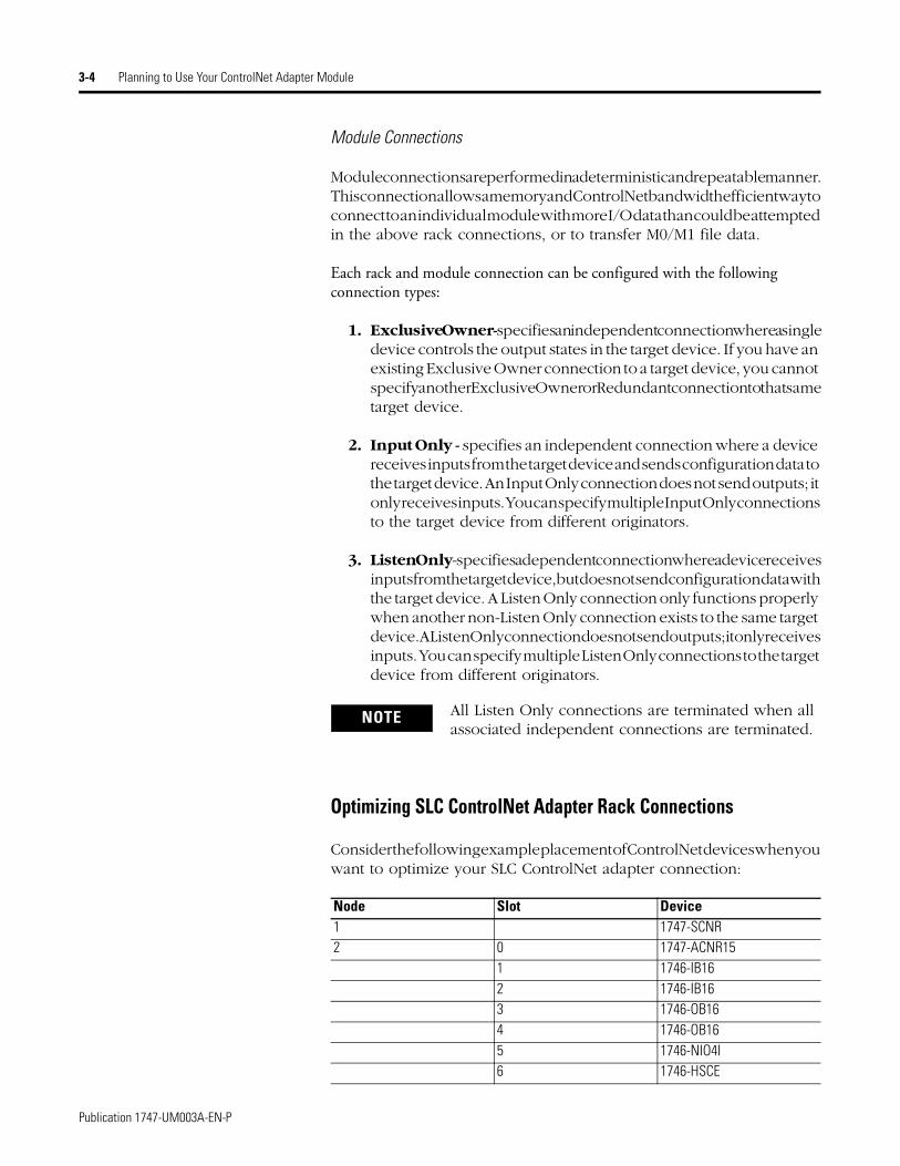
Optimizing SLC ControlNet Adapter Rack Connections
Consider the following example placement of ControlNet devices when you want to optimize your SLC ControlNet adapter connection:
NOTE All Listen Only connections are terminated when all associated independent connections are terminated.
Node Slot Device1 1747-SCNR2 0 1747-ACNR15
1 1746-IB162 1746-IB163 1746-OB164 1746-OB165 1746-NIO4I6 1746-HSCE
Publication 1747-UM003A-EN-P
Planning to Use Your ControlNet Adapter Module 3-5
If we change the default number of words for the input and output values (to 4 and 4) when inserting the connection to the 1747-ACNR15 adapter, Node 2 will produce 4 input words over ControlNet and Node 1 will consume and place those words at addresses I:e.1-4, where the slot 1 inputs correspond to I:e.3 and the slot 2 inputs correspond to I:e.4. In addition, Node 1 will produce 4 output words over ControlNet originating from addresses O:e.1-4 and Node 2 will consume them. A total of 8 words (4 input and 4 output) are transmitted on ControlNet.
Consider the following:
• The 1747-SCNR has 31 input words and 31 output words available for rack connections to 1747-ACNR15 adapters.
• Each 1747-ACNR15 adapter requires 2 input words for status in addition to the input words assigned to the slots.
• Adjust the rack connection size to match the maximum density I/O module:
– Discrete 8-bit Exclusive Owner for 4 and 8-point modules
– Discrete 16-bit Exclusive Owner for 16-point modules
– Discrete 32-bit Exclusive Owner for 32-point modules.
Module Keying
Missing or misplaced modules are detected if the module in question is configured with RSNetWorx as an individual module connection and “compatible module” is selected for electronic keying. If a module connection is attempted to a module which is a missing or misplaced module, the connection will fail. The green OK LED on the initiating scanner will flash and the module will display “I/O” with a partially filled bar indicating all connections are not established, as shown below.
NOTE To optimize ControlNet network bandwidth, place the devices in the following order (left to right on the chassis):
• 1747-ACNR15 adapter
• Discrete input modules
• Discrete output modules
• Any intelligent and/or analog I/O modules that you want to establish individual module connections to
I/O
Publication 1747-UM003A-EN-P
3-6 Planning to Use Your ControlNet Adapter Module
Output Operation During Fault and Idle Modes
RSNetworx allows configuration to characterize each module connection activity during certain operational states.
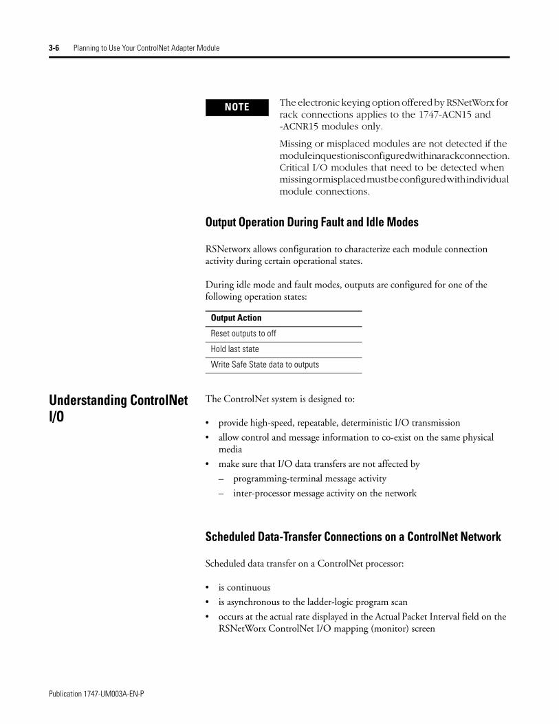
During idle mode and fault modes, outputs are configured for one of the following operation states:
Understanding ControlNet I/O
The ControlNet system is designed to:
• provide high-speed, repeatable, deterministic I/O transmission
• allow control and message information to co-exist on the same physical media
• make sure that I/O data transfers are not affected by
– programming-terminal message activity
– inter-processor message activity on the network
Scheduled Data-Transfer Connections on a ControlNet Network
Scheduled data transfer on a ControlNet processor:
• is continuous
• is asynchronous to the ladder-logic program scan
• occurs at the actual rate displayed in the Actual Packet Interval field on the RSNetWorx ControlNet I/O mapping (monitor) screen
NOTE The electronic keying option offered by RSNetWorx for rack connections applies to the 1747-ACN15 and -ACNR15 modules only.
Missing or misplaced modules are not detected if the module in question is configured within a rack connection. Critical I/O modules that need to be detected when missing or misplaced must be configured with individual module connections.
Output Action
Reset outputs to off
Hold last state
Write Safe State data to outputs
Publication 1747-UM003A-EN-P

Planning to Use Your ControlNet Adapter Module 3-7
The ControlNet system places your scheduled transfers in the first part of each Network Update Interval. Time is automatically reserved for network maintenance. Unscheduled transfers are performed during the time remaining in the interval.
Your application and your configuration-number of nodes, application program, NUT (Network Update Time), amount of scheduled bandwidth used, etc. determine how much time there is for unscheduled messaging.
Sche
dule
d Da
ta Tr
ansf
ers
Logi
c Sc
an
Data Update
Hous
ekee
ping
Data- Table Files
Private- Memory Buffers
Scheduled Data Transfer Program Scan
. . .. . .
You reserve a specific amount of time for all scheduled operations.
The system reserves time for network maintenance
Any time remaining is used for unscheduled operations
IMPORTANT The ControlNet network reserves time for at least one maximum-sized unscheduled transfer per update interval. Depending on how much time there is for unscheduled messaging, every node may not have a chance to send unscheduled data every update interval.
Publication 1747-UM003A-EN-P

3-8 Planning to Use Your ControlNet Adapter Module
Publication 1747-UM003A-EN-P
Chapter 4
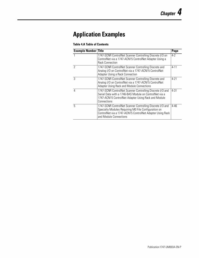
Application ExamplesTable 4.A Table of Contents
Example Number Title Page1 1747-SCNR ControlNet Scanner Controlling Discrete I/O on
ControlNet via a 1747-ACN15 ControlNet Adapter Using a Rack Connection
4-2
2 1747-SCNR ControlNet Scanner Controlling Discrete and Analog I/O on ControlNet via a 1747-ACN15 ControlNet Adapter Using a Rack Connection
4-11
3 1747-SCNR ControlNet Scanner Controlling Discrete and Analog I/O on ControlNet via a 1747-ACN15 ControlNet Adapter Using Rack and Module Connections
4-21
4 1747-SCNR ControlNet Scanner Controlling Discrete I/O and Serial Data with a 1746-BAS Module on ControlNet via a 1747-ACN15 ControlNet Adapter Using Rack and Module Connections
4-31
5 1747-SCNR ControlNet Scanner Controlling Discrete I/O and Specialty Modules Requiring M0 File Configuration on ControlNet via a 1747-ACN15 ControlNet Adapter Using Rack and Module Connections
4-46
1 Publication 1747-UM003A-EN-P
4-2 Application Examples
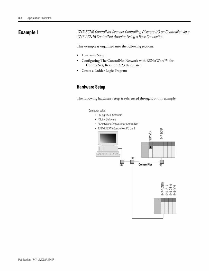
Example 1 1747-SCNR ControlNet Scanner Controlling Discrete I/O on ControlNet via a 1747-ACN15 ControlNet Adapter Using a Rack Connection
This example is organized into the following sections:
• Hardware Setup
• Configuring The ControlNet Network with RSNetWorx™ for ControlNet, Revision 2.23.02 or later
• Create a Ladder Logic Program
Hardware Setup
The following hardware setup is referenced throughout this example.
ControlNet
Computer with:• RSLogix 500 Software• RSLinx Software• RSNetWorx Software for ControlNet• 1784-KTCX15 ControlNet PC Card
tap
tap
SLC
5/04
1747
-SCN
R17
47-A
CN15
1746
-IA16
1746
-OB1
617
46-IV
16
tap
Publication 1747-UM003A-EN-P
Application Examples 4-3
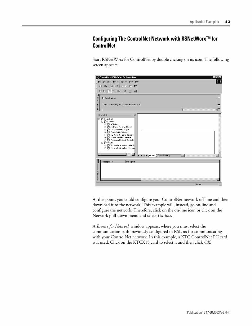
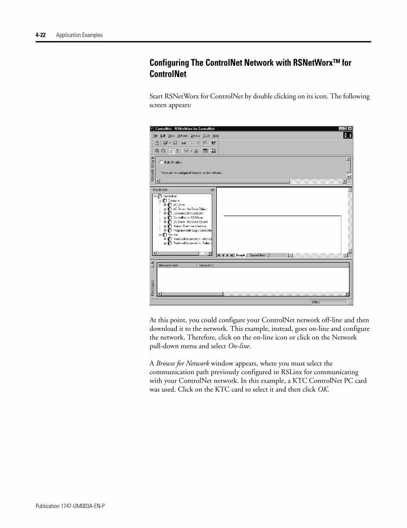
Configuring The ControlNet Network with RSNetWorx™ for ControlNet
Start RSNetWorx for ControlNet by double clicking on its icon. The following screen appears:
At this point, you could configure your ControlNet network off-line and then download it to the network. This example will, instead, go on-line and configure the network. Therefore, click on the on-line icon or click on the Network pull-down menu and select On-line.
A Browse for Network window appears, where you must select the communication path previously configured in RSLinx for communicating with your ControlNet network. In this example, a KTC ControlNet PC card was used. Click on the KTCX15 card to select it and then click OK.
Publication 1747-UM003A-EN-P

4-4 Application Examples
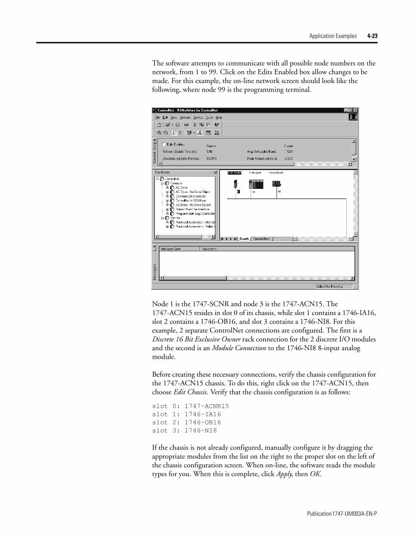
The software attempts to communicate with all possible node numbers on the network, from 1 to 99. Click on the Edits Enabled box to allow changes to be made. For this example, the on-line network screen should look like the following, where node 99 is the programming terminal.
Node 1 is the 1747-SCNR and node 3 is the 1747-ACN15. The 1747-ACN15 resides in slot 0 of its chassis, while slot 1 contains a 1746-IA16, slot 2 contains a 1746-OB16, and slot 3 contains a 1746-IV16. For this example, a single 16-bit rack connection will be configured to read/write the three discrete I/O modules.
Before creating the connection, verify the chassis configuration for the 1747-ACN15 chassis. To do this, right click on the 1747-ACN15, then choose Edit Chassis. Verify that the chassis configuration is as follows:
slot 0: 1747-ACNR15slot 1: 1746-IA16slot 2: 1746-OB16slot 3: 1746-IV16
If the chassis is not already configured, manually configure it by dragging the appropriate modules from the list on the right to the proper slot on the left of the chassis configuration screen. When on-line, the software reads the module types for you. When this is complete, click Apply, then OK.
Publication 1747-UM003A-EN-P
Application Examples 4-5
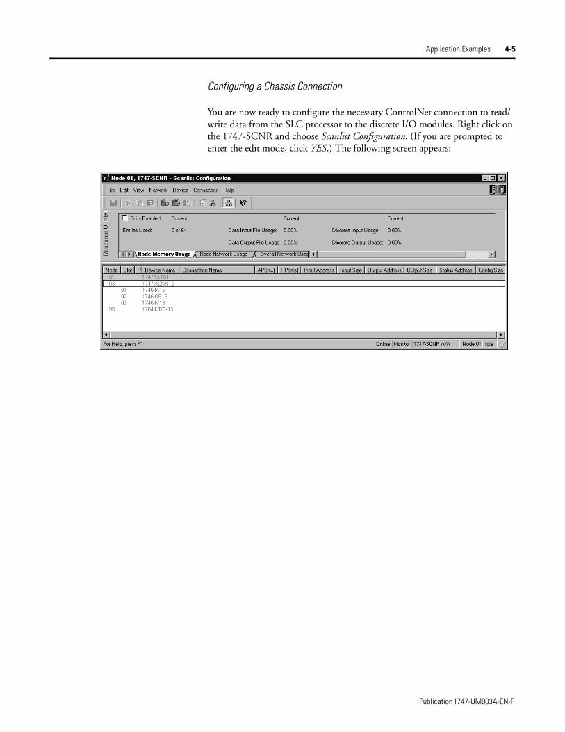
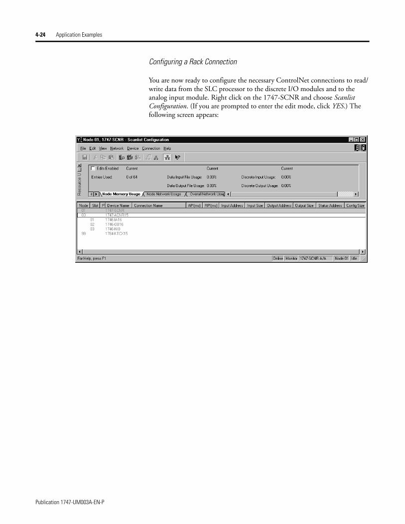
Configuring a Chassis Connection
You are now ready to configure the necessary ControlNet connection to read/write data from the SLC processor to the discrete I/O modules. Right click on the 1747-SCNR and choose Scanlist Configuration. (If you are prompted to enter the edit mode, click YES.) The following screen appears:
Publication 1747-UM003A-EN-P
4-6 Application Examples
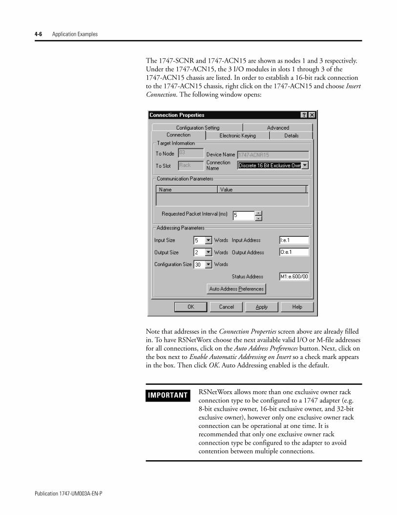
The 1747-SCNR and 1747-ACN15 are shown as nodes 1 and 3 respectively. Under the 1747-ACN15, the 3 I/O modules in slots 1 through 3 of the 1747-ACN15 chassis are listed. In order to establish a 16-bit rack connection to the 1747-ACN15 chassis, right click on the 1747-ACN15 and choose Insert Connection. The following window opens:
Note that addresses in the Connection Properties screen above are already filled in. To have RSNetWorx choose the next available valid I/O or M-file addresses for all connections, click on the Auto Address Preferences button. Next, click on the box next to Enable Automatic Addressing on Insert so a check mark appears in the box. Then click OK. Auto Addressing enabled is the default.
IMPORTANT RSNetWorx allows more than one exclusive owner rack connection type to be configured to a 1747 adapter (e.g. 8-bit exclusive owner, 16-bit exclusive owner, and 32-bit exclusive owner), however only one exclusive owner rack connection can be operational at one time. It is recommended that only one exclusive owner rack connection type be configured to the adapter to avoid contention between multiple connections.
Publication 1747-UM003A-EN-P
Application Examples 4-7
The Connection Name, by default, is Discrete 16-Bit Exclusive Owner and this is the 16-bit rack connection you want. The first available I/O addresses are I:3.1 and O:3.1, where the 1747-SCNR is in slot 3 of the processor chassis. The first available starting I/O addresses have been placed into the Input Address and Output Address fields, because automatic addressing was previously selected in the Auto Address Preference screen. Words I:3.0 and O:3.0 contain status and control data and are not used for I/O data.
Note that the input data from the 1746-IA16 is found in the processor’s input image word I:3.3 and the output data written to the 1746-OB16 module is from the processor’s output image word O:3.2. The input data from the 1746-IV16 is in the processor’s input image word I:3.5.
The Status Address field must also be filled in. This field supplies Connection Status information to the processor for each unique connection. The starting bit address for this field must be an even number because two consecutive bits are used as status for each connection. The even numbered bit indicates whether the connection is open or closed. The odd numbered bit indicates whether the connection is in normal operation or Idle mode. In this example, the starting address chosen is the first available bit pair, M1:3.600/00.
IMPORTANT If a rack connection type is changed to a smaller bit configuration e.g. 32-bit to 16-bit, or 16-bit to 8-bit, the unused bits for the new connection remains in their previously programmed states for program mode or lost communications e.g. last state, safe state, reset off.
NOTE There is a 2-word offset for input data for rack connections. Therefore, for this example, the input data for the input module in slot 1 of the remote 1747-ACN15 chassis is written to I:3.3 in the SLC processor’s input image. The input module in slot 3 is written to I:3.5.
The starting input address configured in RSNetWorx for this rack connection was I:3.1, but I:3.1 and I:3.2 are used for rack slot status information. Note the resulting input size of 5 shown in the Connection Properties screen. Therefore, the actual input data begins after the 2 words of status information. I:3.4 is not used in this example because an output module resides in slot 2.
Also, note that there is no offset for the outputs in a rack connection. O:3.2 is the output image word written to the output module located in slot 2 of the 1747-ACN15 chassis. O:3.1 is also not used in this example because an input card is in slot 1.
Publication 1747-UM003A-EN-P
4-8 Application Examples
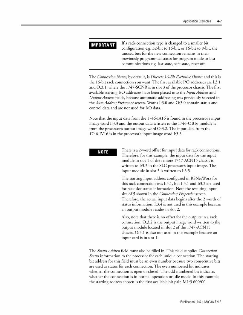
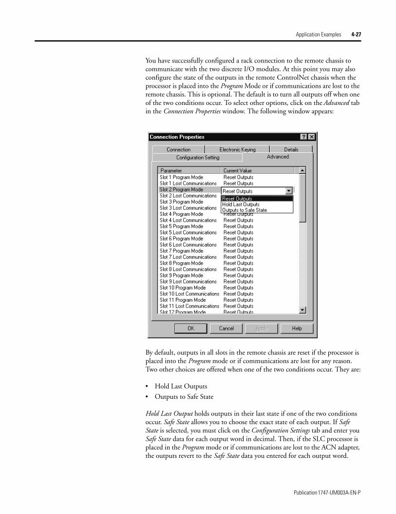
You have successfully configured a rack connection to the remote chassis to communicate with the discrete I/O modules. At this point, you may also configure the state of the outputs in the remote ControlNet chassis when the controlling processor is placed into the Program mode or if communications are lost to the remote chassis. This is optional. The default is to turn all outputs off when one of the two conditions occur. To select other options, click on the Advanced tab in the Connection Properties window. The following window appears:
By default, outputs in all slots in the remote chassis are reset if the processor is placed into the Program mode or if communications are lost for any reason. Two other choices are offered when one of the two conditions occur. They are:
• Hold Last Outputs
• Outputs to Safe State
Hold Last Outputs holds outputs in their last state if one of the two conditions occur. Safe State allows you to choose the exact state of each output. If Safe State is selected, you must click on the Configuration Settings tab and enter your Safe State data for each output word in decimal. Then, if the SLC processor is
Publication 1747-UM003A-EN-P
Application Examples 4-9
placed in the Program mode or if communications are lost to the ACN15 adapter, the outputs revert to the Safe State data you entered for each output word.
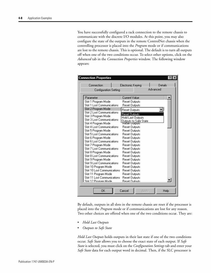
Click Apply, then OK to return to the ScanList Configuration window which should look like the following:
You have now successfully configured your rack connection to read/write data between the SLC processor and the remote ControlNet chassis. All that remains is to Save this configuration to the network keeper which, in this case, is the 1747-SCNR.
Click on the Save icon or choose the File pull-down menu and select Save. You are prompted to Optimize and re-write schedule for all connections. Click OK, then click YES to the subsequent warning message. Your network configuration information is then written to the network keeper and scanner devices.
The display on the front of your 1747-SCNR should show a Full Glass next to I/O. This indicates that all configured connections have been successfully downloaded to the scanner. In addition, the A and OK LEDs should be solid green and the B LED should be off, unless you are using the redundant media option, which is not being used in this example. The 1747-ACN15 should be displaying that it is active (ACTV) and its LEDs should be solid green for A and OK.
Publication 1747-UM003A-EN-P

4-10 Application Examples
Create a Ladder Logic Program
The final step is to write a ladder program for the SLC processor, including configuring the 1747-SCNR for slot 3 of the processor’s chassis. After downloading the program to your processor, place it into the RUN mode. Your program should now be able to read data from the 1746-IA16 in word I:3.3, write to the 1746-OB16 in word O:3.2 and read data from the 1746-IV16 in word I:3.5.
Note that your ladder program should also contain an unconditional rung with an OTE instruction addressed to the SCNR scanner’s RUN/IDLE bit, O:3.0/10 for this example. When the SLC processor is placed into the RUN mode, this rung sets the SCNR scanner’s RUN/IDLE bit and places the scanner into the RUN mode as well. The scanner begins executing the configured connections when the RUN/IDLE bit is set.
Publication 1747-UM003A-EN-P
Application Examples 4-11
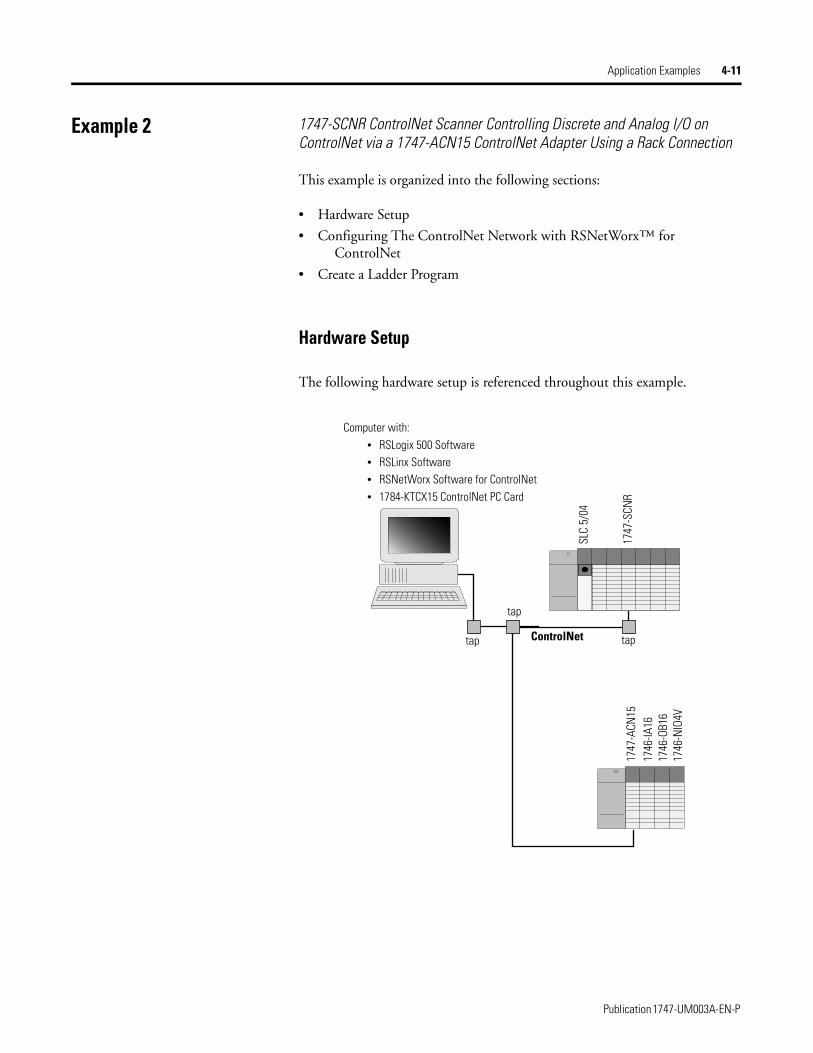
Example 2 1747-SCNR ControlNet Scanner Controlling Discrete and Analog I/O on ControlNet via a 1747-ACN15 ControlNet Adapter Using a Rack Connection
This example is organized into the following sections:
• Hardware Setup
• Configuring The ControlNet Network with RSNetWorx™ for ControlNet
• Create a Ladder Program
Hardware Setup
The following hardware setup is referenced throughout this example.
ControlNet
Computer with:• RSLogix 500 Software• RSLinx Software• RSNetWorx Software for ControlNet• 1784-KTCX15 ControlNet PC Card
tap
tap
SLC
5/04
1747
-SCN
R17
47-A
CN15
1746
-IA16
1746
-OB1
617
46-N
IO4V
tap
Publication 1747-UM003A-EN-P

4-12 Application Examples
Configuring The ControlNet Network with RSNetWorx™ for ControlNet
Start RSNetWorx for ControlNet by double clicking on its icon. The following screen appears:
At this point, you could configure your ControlNet network off-line and then download it to the network. This example, instead, goes on-line and configure the network. Therefore, click on the on-line icon or click on the Network pull-down menu and select On-line.
A Browse for Network window appears, where you must select the communication path previously configured in RSLinx for communicating with your ControlNet network. In this example, a 1784-KTCX15 ControlNet PC card was used. Click on the KTC card to select it and then click OK.
Publication 1747-UM003A-EN-P
Application Examples 4-13
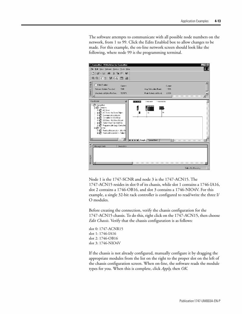
The software attempts to communicate with all possible node numbers on the network, from 1 to 99. Click the Edits Enabled box to allow changes to be made. For this example, the on-line network screen should look like the following, where node 99 is the programming terminal.
Node 1 is the 1747-SCNR and node 3 is the 1747-ACN15. The 1747-ACN15 resides in slot 0 of its chassis, while slot 1 contains a 1746-IA16, slot 2 contains a 1746-OB16, and slot 3 contains a 1746-NIO4V. For this example, a single 32-bit rack controller is configured to read/write the three I/O modules.
Before creating the connection, verify the chassis configuration for the 1747-ACN15 chassis. To do this, right click on the 1747-ACN15, then choose Edit Chassis. Verify that the chassis configuration is as follows:
slot 0: 1747-ACNR15slot 1: 1746-IA16slot 2: 1746-OB16slot 3: 1746-NIO4V
If the chassis is not already configured, manually configure it by dragging the appropriate modules from the list on the right to the proper slot on the left of the chassis configuration screen. When on-line, the software reads the module types for you. When this is complete, click Apply, then OK.
Publication 1747-UM003A-EN-P

4-14 Application Examples
Configuring a Rack Connection
You are now ready to configure the necessary ControlNet connection to read/write data from the SLC processor to the discrete I/O modules and to the 1746-NIO4V analog module. Right click on the 1747-SCNR and choose Scanlist Configuration. (If you are prompted to enter the edit mode, click YES.) The following screen appears:
Publication 1747-UM003A-EN-P

Application Examples 4-15
The 1747-SCNR and 1747-ACN15 are shown as nodes 1 and 3 respectively. Under the 1747-ACN15, the 3 I/O modules in slots 1 through 3 of the 1747-ACN15 chassis are listed. We specify a 32-bit rack connection so that the two words of analog input and two words of analog output data from the 1746-NIO4V module can be transferred via the rack connection. In order to establish a 32-bit rack connection to the 1747-ACN15 chassis, right click on the 1747-ACN15 and choose Insert Connection. The following window opens:
Note that addresses in the Connection Properties screen above are already filled in. To have RSNetWorx choose the next available valid I/O or M-file addresses for all connections, click on the Auto Address Preferences button. Next, click on the box next to Enable Automatic Addressing on Insert so a check mark appears in the box. Then click OK. Automatic Addressing enabled is the default.
Publication 1747-UM003A-EN-P
4-16 Application Examples
The Connection Name, by default, is Discrete 16-Bit Exclusive Owner. Change this to Discrete 32-bit Exclusive Owner. The first available I/O addresses are I:3.1 and O:3.1, where the 1747-SCNR is in slot 3 of the processor chassis. The first available starting I/O addresses have been placed into the Input Address and Output Address fields, because automatic addressing was previously selected in the Auto Address Preference screen. Words I:3.0 and O:3.0 are used for status and control data.
Note that the input data from the 1746-IA16 is found in the processor’s input image word I:3.3 and the output data written to the 1746-OB16 module is from the processor’s output image word O:3.3. The 1746-NIO4V input data is in I:3.7 and I:3.8, and the output data is in O:3.5 and O:3.6.
IMPORTANT RSNetWorx allows more than one exclusive owner rack connection type to be configured to a 1747 adapter (e.g. 8-bit exclusive owner, 16-bit exclusive owner, and 32-bit exclusive owner), however only one exclusive owner rack connection can be operational at one time. It is recommended that only one exclusive owner rack connection type be configured to the adapter to avoid contention between multiple connections.
IMPORTANT If a rack connection type is changed to a smaller bit configuration e.g. 32-bit to 16-bit, or 16-bit to 8-bit, the unused bits for the new connection remains in their previously programmed states for program mode or lost communications e.g. last state, safe state, reset off.
Publication 1747-UM003A-EN-P
Application Examples 4-17
The Status Address field must also be filled in. This field supplies Connection Status information to the processor for each unique connection. The starting bit address for this field must be an even number because two consecutive bits are used as status for each connection. The even numbered bit indicates whether the connection is open or closed. The odd numbered bit indicates whether the connection is in normal operation or Idle mode. In this example, the starting address chosen is the first available bit pair, M1:3.600/00.
NOTE There is a 2-word offset for input data for rack connections. Therefore, for this example, the input data for the input module in slot 1 of the remote 1747-ACN15 chassis is written to I:3.3 in the SLC processor’s input image.
The starting input address configured in RSNetWorx for this rack connection was I:3.1, but I:3.1 and I:3.2 are used for rack slot status information. Therefore, the actual input data begins after the 2 words of status information. I:3.4 is not used in this example because although 32 input bits are assigned to slot 1, the 1746-IA16 only uses the first 16 input bits.
I:3.5 and I:3.6 are not used in this example because an output module resides in slot 2. Also, note that there is no offset for the outputs in a rack connection. O:3.3 is the output image word written to the output module located in slot 2 of the 1747-ACN15 chassis.
Publication 1747-UM003A-EN-P
4-18 Application Examples
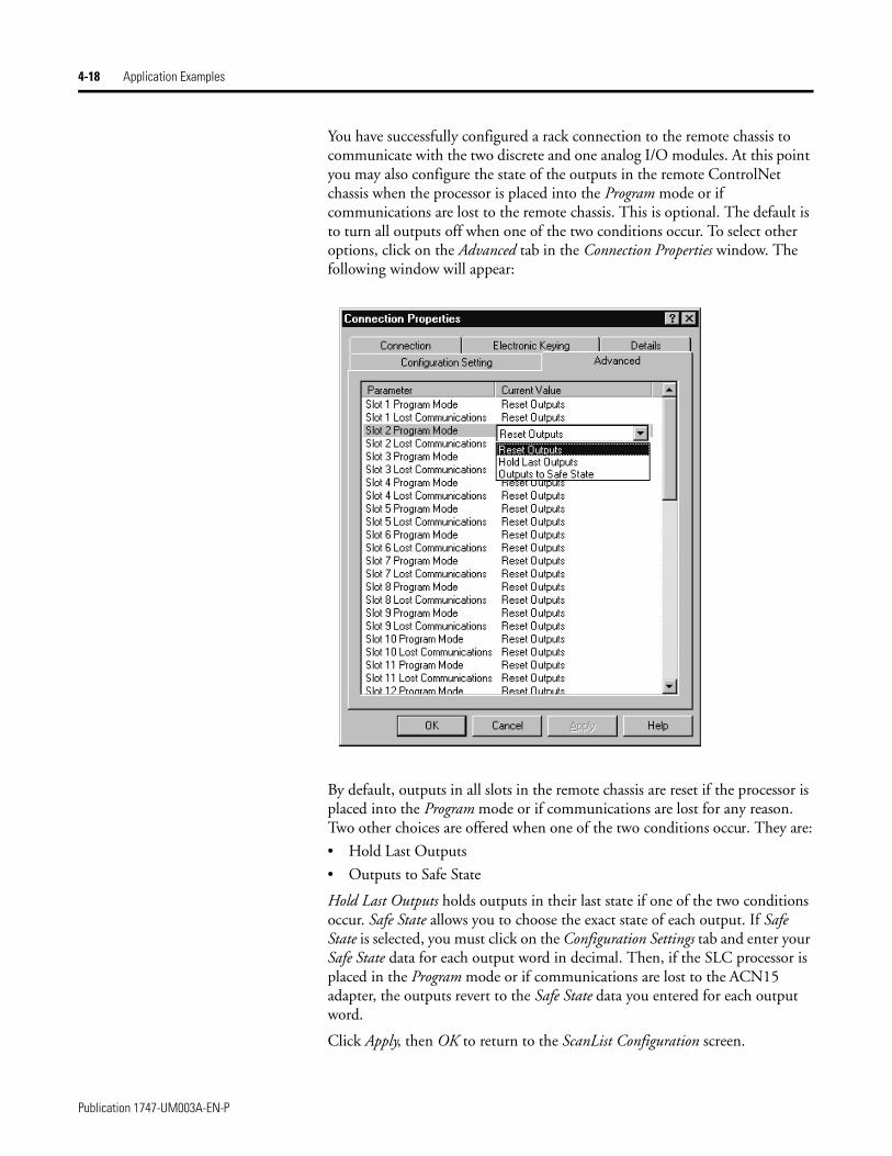
You have successfully configured a rack connection to the remote chassis to communicate with the two discrete and one analog I/O modules. At this point you may also configure the state of the outputs in the remote ControlNet chassis when the processor is placed into the Program mode or if communications are lost to the remote chassis. This is optional. The default is to turn all outputs off when one of the two conditions occur. To select other options, click on the Advanced tab in the Connection Properties window. The following window will appear:
By default, outputs in all slots in the remote chassis are reset if the processor is placed into the Program mode or if communications are lost for any reason. Two other choices are offered when one of the two conditions occur. They are:
• Hold Last Outputs
• Outputs to Safe State
Hold Last Outputs holds outputs in their last state if one of the two conditions occur. Safe State allows you to choose the exact state of each output. If Safe State is selected, you must click on the Configuration Settings tab and enter your Safe State data for each output word in decimal. Then, if the SLC processor is placed in the Program mode or if communications are lost to the ACN15 adapter, the outputs revert to the Safe State data you entered for each output word.
Click Apply, then OK to return to the ScanList Configuration screen.
Publication 1747-UM003A-EN-P
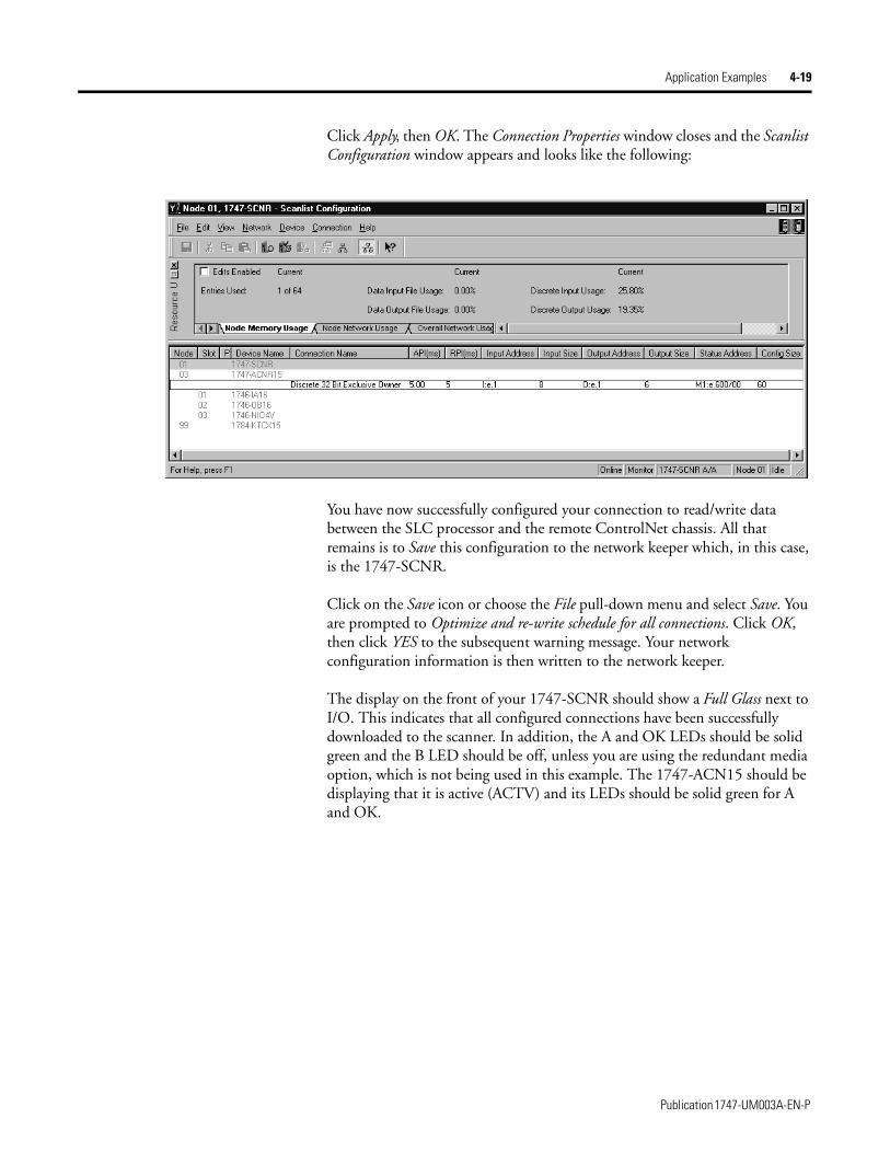
Application Examples 4-19
Click Apply, then OK. The Connection Properties window closes and the Scanlist Configuration window appears and looks like the following:
You have now successfully configured your connection to read/write data between the SLC processor and the remote ControlNet chassis. All that remains is to Save this configuration to the network keeper which, in this case, is the 1747-SCNR.
Click on the Save icon or choose the File pull-down menu and select Save. You are prompted to Optimize and re-write schedule for all connections. Click OK, then click YES to the subsequent warning message. Your network configuration information is then written to the network keeper.
The display on the front of your 1747-SCNR should show a Full Glass next to I/O. This indicates that all configured connections have been successfully downloaded to the scanner. In addition, the A and OK LEDs should be solid green and the B LED should be off, unless you are using the redundant media option, which is not being used in this example. The 1747-ACN15 should be displaying that it is active (ACTV) and its LEDs should be solid green for A and OK.
Publication 1747-UM003A-EN-P
4-20 Application Examples
Create a Ladder Program
The final step is to write a ladder program for the SLC processor, including configuring the 1747-SCNR for slot 3 of the processor’s chassis. After downloading the program to your processor, place it into the RUN mode. Your program should now be able to read data from the 1746-IA16 in word I:3.3 and write to the 1746-OB16 in word O:3.3. The analog input data resides in words I:3.7 and I:3.8, while the analog output data must be copied to words O:3.5 and O:3.6.
Note that your ladder program should also contain an unconditional rung with an OTE instruction addressed to the SCNR scanner’s RUN/IDLE bit, O:3.0/10 for this example. When the SLC processor is placed into the RUN mode, this rung sets the SCNR scanner’s RUN/IDLE bit and places the scanner into the RUN mode as well. The scanner begins executing the configured connections when the RUN/IDLE bit is set.
Publication 1747-UM003A-EN-P
Application Examples 4-21
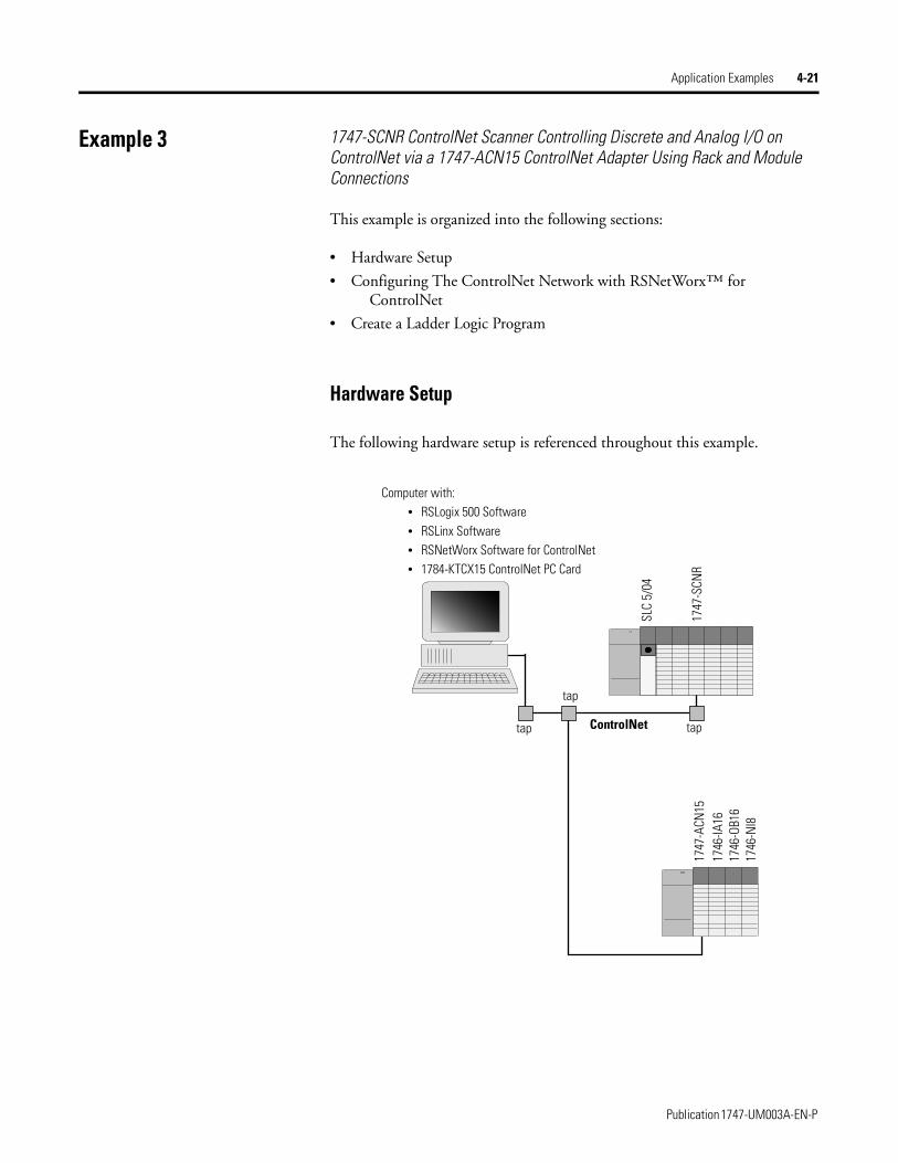
Example 3 1747-SCNR ControlNet Scanner Controlling Discrete and Analog I/O on ControlNet via a 1747-ACN15 ControlNet Adapter Using Rack and Module Connections
This example is organized into the following sections:
• Hardware Setup
• Configuring The ControlNet Network with RSNetWorx™ for ControlNet
• Create a Ladder Logic Program
Hardware Setup
The following hardware setup is referenced throughout this example.
ControlNet
Computer with:• RSLogix 500 Software• RSLinx Software• RSNetWorx Software for ControlNet• 1784-KTCX15 ControlNet PC Card
tap
tap
SLC
5/04
1747
-SCN
R17
47-A
CN15
1746
-IA16
1746
-OB1
617
46-N
I8
tap
Publication 1747-UM003A-EN-P
4-22 Application Examples
Configuring The ControlNet Network with RSNetWorx™ for ControlNet
Start RSNetWorx for ControlNet by double clicking on its icon. The following screen appears:
At this point, you could configure your ControlNet network off-line and then download it to the network. This example, instead, goes on-line and configure the network. Therefore, click on the on-line icon or click on the Network pull-down menu and select On-line.
A Browse for Network window appears, where you must select the communication path previously configured in RSLinx for communicating with your ControlNet network. In this example, a KTC ControlNet PC card was used. Click on the KTC card to select it and then click OK.
Publication 1747-UM003A-EN-P
Application Examples 4-23
The software attempts to communicate with all possible node numbers on the network, from 1 to 99. Click on the Edits Enabled box allow changes to be made. For this example, the on-line network screen should look like the following, where node 99 is the programming terminal.
Node 1 is the 1747-SCNR and node 3 is the 1747-ACN15. The 1747-ACN15 resides in slot 0 of its chassis, while slot 1 contains a 1746-IA16, slot 2 contains a 1746-OB16, and slot 3 contains a 1746-NI8. For this example, 2 separate ControlNet connections are configured. The first is a Discrete 16 Bit Exclusive Owner rack connection for the 2 discrete I/O modules and the second is an Module Connection to the 1746-NI8 8-input analog module.
Before creating these necessary connections, verify the chassis configuration for the 1747-ACN15 chassis. To do this, right click on the 1747-ACN15, then choose Edit Chassis. Verify that the chassis configuration is as follows:
slot 0: 1747-ACNR15slot 1: 1746-IA16slot 2: 1746-OB16slot 3: 1746-NI8
If the chassis is not already configured, manually configure it by dragging the appropriate modules from the list on the right to the proper slot on the left of the chassis configuration screen. When on-line, the software reads the module types for you. When this is complete, click Apply, then OK.
Publication 1747-UM003A-EN-P
4-24 Application Examples
Configuring a Rack Connection
You are now ready to configure the necessary ControlNet connections to read/write data from the SLC processor to the discrete I/O modules and to the analog input module. Right click on the 1747-SCNR and choose Scanlist Configuration. (If you are prompted to enter the edit mode, click YES.) The following screen appears:
Publication 1747-UM003A-EN-P
Application Examples 4-25
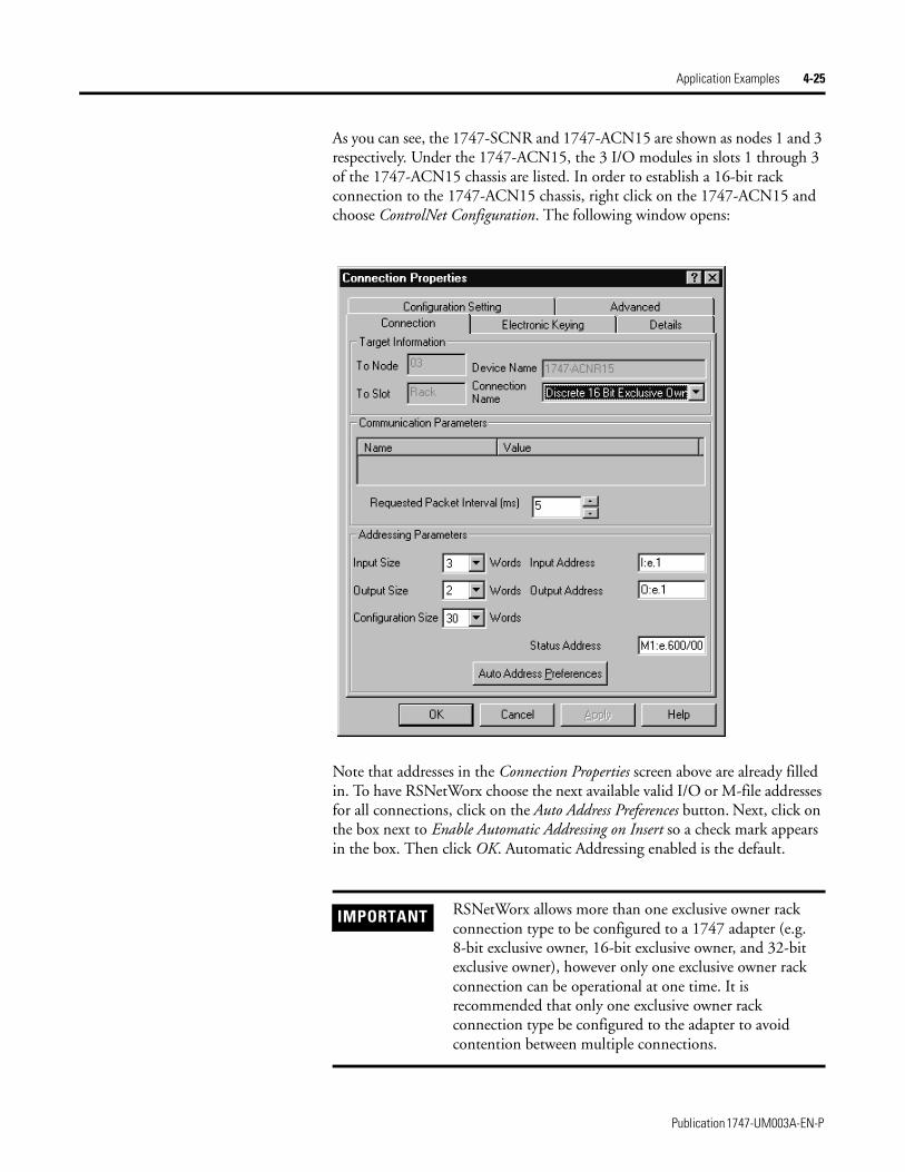
As you can see, the 1747-SCNR and 1747-ACN15 are shown as nodes 1 and 3 respectively. Under the 1747-ACN15, the 3 I/O modules in slots 1 through 3 of the 1747-ACN15 chassis are listed. In order to establish a 16-bit rack connection to the 1747-ACN15 chassis, right click on the 1747-ACN15 and choose ControlNet Configuration. The following window opens:
Note that addresses in the Connection Properties screen above are already filled in. To have RSNetWorx choose the next available valid I/O or M-file addresses for all connections, click on the Auto Address Preferences button. Next, click on the box next to Enable Automatic Addressing on Insert so a check mark appears in the box. Then click OK. Automatic Addressing enabled is the default.
IMPORTANT RSNetWorx allows more than one exclusive owner rack connection type to be configured to a 1747 adapter (e.g. 8-bit exclusive owner, 16-bit exclusive owner, and 32-bit exclusive owner), however only one exclusive owner rack connection can be operational at one time. It is recommended that only one exclusive owner rack connection type be configured to the adapter to avoid contention between multiple connections.
Publication 1747-UM003A-EN-P

4-26 Application Examples
The Connection Name by default is Discrete 16-Bit Exclusive Owner and this is the 16-bit rack connection you want. The first available I/O addresses are I:3.1 and O:3.1, where the 1747-SCNR is in slot 3 of the processor chassis. The first available starting I/O addresses have been placed into the Input Address and Output Address fields, because automatic addressing was previously selected in the Auto Address Preference screen. Words I:3.0 and O:3.0 are used for status and control data.
Note that the input data from the 1746-IA16 is found in the processor’s input image word I:3.3 and the output data written to the 1746-OB16 module is from the processor’s output image word O:3.2.
The Status Address field must also be filled in. This field supplies Connection Status information to the processor for each unique connection. The starting bit address for this field must be an even number because two consecutive bits are used as status for each connection. The even numbered bit indicates whether the connection is open or closed. The odd numbered bit indicates whether the connection is in normal operation or Idle mode. In this example, the starting address chosen is the first available bit pair, M1:3.600/00.
IMPORTANT If a rack connection type is changed to a smaller bit configuration e.g. 32-bit to 16-bit, or 16-bit to 8-bit, the unused bits for the new connection remains in their previously programmed states for program mode or lost communications e.g. last state, safe state, reset off.
NOTE There is a 2-word offset for input data for rack connections. Therefore, for this example, the input data for the input module in slot 1 of the remote 1747-ACN15 chassis is written to I:3.3 in the SLC processor’s input image.
The starting input address configured in RSNetWorx for this rack connection was I:3.1, but I:3.1 and I:3.2 are used for rack slot status information. Therefore, the actual input data begins after the 2 words of status information. I:3.4 and I:3.5 are not used in this example because an output module resides in slot 2 and an analog module resides in slot 3.
Also, note that there is no offset for the outputs in a rack connection. O:3.2 is the output image word written to the output module located in slot 2 of the 1747-ACN15 chassis. O:3.1 is not used because an input module resides in slot 1. In addition, no offset applies to module connections at all.
Publication 1747-UM003A-EN-P
Application Examples 4-27
You have successfully configured a rack connection to the remote chassis to communicate with the two discrete I/O modules. At this point you may also configure the state of the outputs in the remote ControlNet chassis when the processor is placed into the Program Mode or if communications are lost to the remote chassis. This is optional. The default is to turn all outputs off when one of the two conditions occur. To select other options, click on the Advanced tab in the Connection Properties window. The following window appears:
By default, outputs in all slots in the remote chassis are reset if the processor is placed into the Program mode or if communications are lost for any reason. Two other choices are offered when one of the two conditions occur. They are:
• Hold Last Outputs
• Outputs to Safe State
Hold Last Output holds outputs in their last state if one of the two conditions occur. Safe State allows you to choose the exact state of each output. If Safe State is selected, you must click on the Configuration Settings tab and enter you Safe State data for each output word in decimal. Then, if the SLC processor is placed in the Program mode or if communications are lost to the ACN adapter, the outputs revert to the Safe State data you entered for each output word.
Publication 1747-UM003A-EN-P
4-28 Application Examples
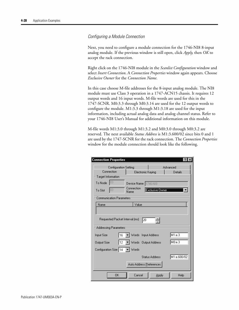
Configuring a Module Connection
Next, you need to configure a module connection for the 1746-NI8 8-input analog module. If the previous window is still open, click Apply, then OK to accept the rack connection.
Right click on the 1746-NI8 module in the Scanlist Configuration window and select Insert Connection. A Connection Properties window again appears. Choose Exclusive Owner for the Connection Name.
In this case choose M-file addresses for the 8-input analog module. The NI8 module must use Class 3 operation in a 1747-ACN15 chassis. It requires 12 output words and 16 input words. M-file words are used for this in the 1747-SCNR. M0:3.3 through M0:3.14 are used for the 12 output words to configure the module. M1:3.3 through M1:3.18 are used for the input information, including actual analog data and analog channel status. Refer to your 1746-NI8 User’s Manual for additional information on this module.
M-file words M1:3.0 through M1:3.2 and M0:3.0 through M0:3.2 are reserved. The next available Status Address is M1:3.600/02 since bits 0 and 1 are used by the 1747-SCNR for the rack connection. The Connection Properties window for the module connection should look like the following.
Publication 1747-UM003A-EN-P
4-29
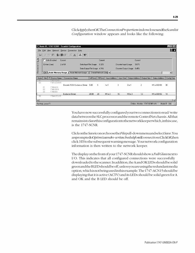
Click Apply, then OK. The Connection Properties window closes and the Scanlist Configuration window appears and looks like the following:
You have now successfully configured your two connections to read/write data between the SLC processor and the remote ControlNet chassis. All that remains is to Save this configuration to the network keeper which, in this case, is the 1747-SCNR.
Click on the Save icon or choose the File pull-down menu and select Save. You are prompted to Optimize and re-write schedule for all connections. Click OK, then click YES to the subsequent warning message. Your network configuration information is then written to the network keeper.
The display on the front of your 1747-SCNR should show a Full Glass next to I/O. This indicates that all configured connections were successfully downloaded to the scanner. In addition, the A and OK LEDs should be solid green and the B LED should be off, unless you are using the redundant media option, which is not being used in this example. The 1747-ACN15 should be displaying that it is active (ACTV) and its LEDs should be solid green for A and OK and the B LED should be off.
Publication 1747-UM003A-EN-P
4-30
Create a Ladder Logic Program
The final step is to write a ladder program for the SLC processor, including configuring the 1747-SCNR for slot 3 of the processor’s chassis. After downloading the program to your processor, place it into the RUN mode. Your program should now be able to read data from the 1746-IA16 in word I:3.3 and write to the 1746-OB16 in word O:3.2. The analog input data and channel status will reside in words M1:3.3 through M1:3.18, while the analog module configuration data must be copied to words M0:3.3 through M0:3.14.
Note that your ladder program should also contain an unconditional rung with an OTE instruction addressed to the SCNR scanner’s RUN/IDLE bit, O:3.0/10 for this example. When the SLC processor is placed into the RUN mode, this rung sets the SCNR scanner’s RUN/IDLE bit and places the scanner into the RUN mode as well. The scanner begins executing the configured connections when the RUN/IDLE bit is set.
Publication 1747-UM003A-EN-P
4-31
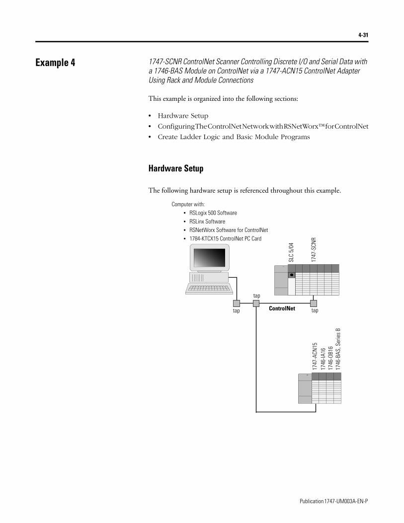
Example 4 1747-SCNR ControlNet Scanner Controlling Discrete I/O and Serial Data with a 1746-BAS Module on ControlNet via a 1747-ACN15 ControlNet Adapter Using Rack and Module Connections
This example is organized into the following sections:
• Hardware Setup
• Configuring The ControlNet Network with RSNetWorx™ for ControlNet
• Create Ladder Logic and Basic Module Programs
Hardware Setup
The following hardware setup is referenced throughout this example.
ControlNet
Computer with:• RSLogix 500 Software• RSLinx Software• RSNetWorx Software for ControlNet• 1784-KTCX15 ControlNet PC Card
tap
tap
SLC
5/04
1747
-SCN
R17
47-A
CN15
1746
-IA16
1746
-OB1
617
46-B
AS, S
erie
s B
tap
Publication 1747-UM003A-EN-P

4-32
Configuring The ControlNet Network with RSNetWorx™ for ControlNet
Start RSNetWorx for ControlNet by double clicking on its icon. The following screen appears:
At this point, you could configure your ControlNet network off-line and then download it to the network. This example, instead, goes on-line and configure the network. Therefore, click on the on-line icon or click on the Network pull-down menu and select On-line.
A Browse for Network window appears, where you must select the communication path previously configured in RSLinx for communicating with your ControlNet network. In this example, a KTCX ControlNet PC card was used. Click on the KTCX15 card to select it and then click OK.
Publication 1747-UM003A-EN-P
4-33
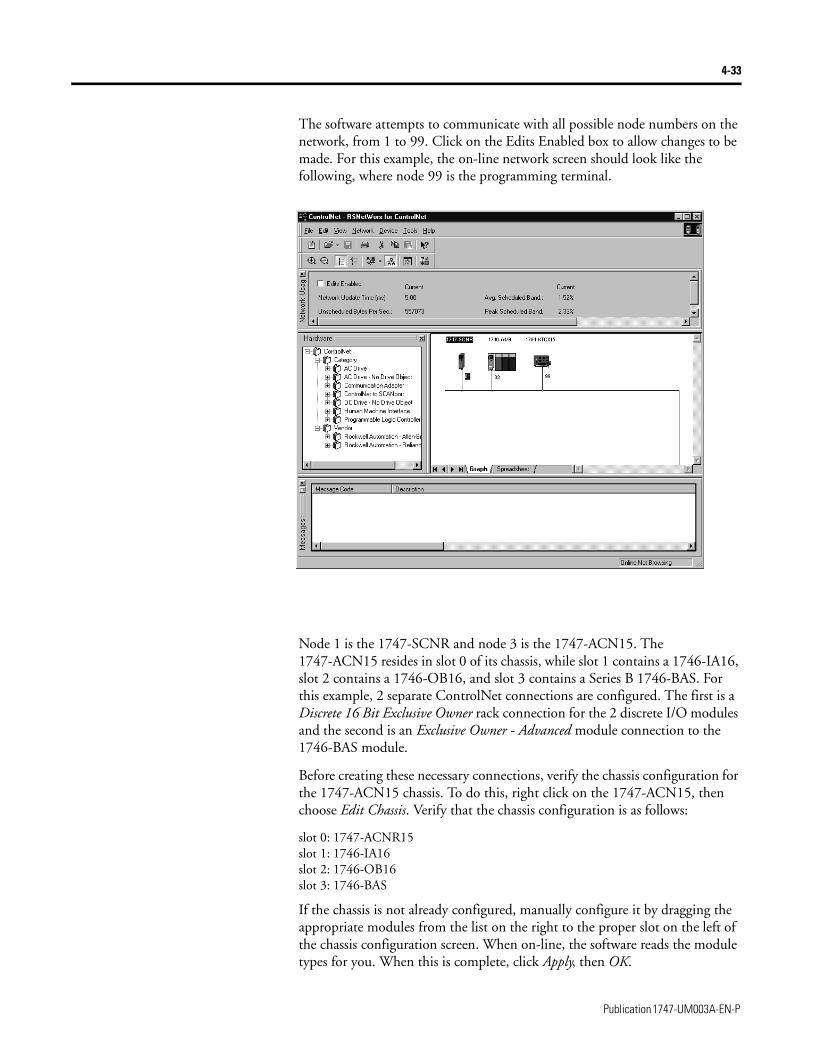
The software attempts to communicate with all possible node numbers on the network, from 1 to 99. Click on the Edits Enabled box to allow changes to be made. For this example, the on-line network screen should look like the following, where node 99 is the programming terminal.
Node 1 is the 1747-SCNR and node 3 is the 1747-ACN15. The 1747-ACN15 resides in slot 0 of its chassis, while slot 1 contains a 1746-IA16, slot 2 contains a 1746-OB16, and slot 3 contains a Series B 1746-BAS. For this example, 2 separate ControlNet connections are configured. The first is a Discrete 16 Bit Exclusive Owner rack connection for the 2 discrete I/O modules and the second is an Exclusive Owner - Advanced module connection to the 1746-BAS module.
Before creating these necessary connections, verify the chassis configuration for the 1747-ACN15 chassis. To do this, right click on the 1747-ACN15, then choose Edit Chassis. Verify that the chassis configuration is as follows:
slot 0: 1747-ACNR15slot 1: 1746-IA16slot 2: 1746-OB16slot 3: 1746-BAS
If the chassis is not already configured, manually configure it by dragging the appropriate modules from the list on the right to the proper slot on the left of the chassis configuration screen. When on-line, the software reads the module types for you. When this is complete, click Apply, then OK.
Publication 1747-UM003A-EN-P
4-34
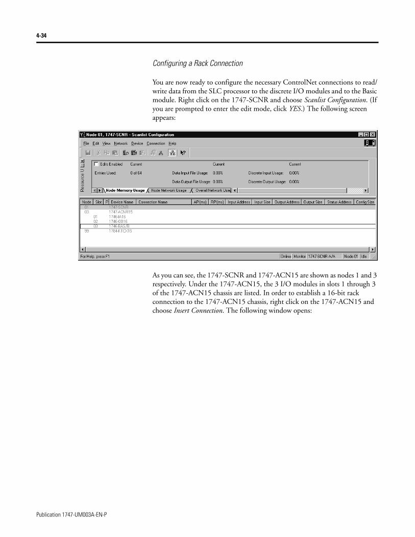
Configuring a Rack Connection
You are now ready to configure the necessary ControlNet connections to read/write data from the SLC processor to the discrete I/O modules and to the Basic module. Right click on the 1747-SCNR and choose Scanlist Configuration. (If you are prompted to enter the edit mode, click YES.) The following screen appears:
As you can see, the 1747-SCNR and 1747-ACN15 are shown as nodes 1 and 3 respectively. Under the 1747-ACN15, the 3 I/O modules in slots 1 through 3 of the 1747-ACN15 chassis are listed. In order to establish a 16-bit rack connection to the 1747-ACN15 chassis, right click on the 1747-ACN15 and choose Insert Connection. The following window opens:
Publication 1747-UM003A-EN-P
4-35
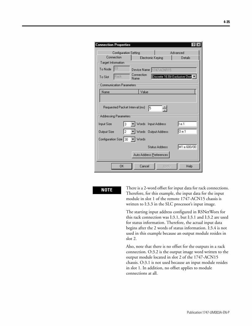
NOTE There is a 2-word offset for input data for rack connections. Therefore, for this example, the input data for the input module in slot 1 of the remote 1747-ACN15 chassis is written to I:3.3 in the SLC processor’s input image.
The starting input address configured in RSNetWorx for this rack connection was I:3.1, but I:3.1 and I:3.2 are used for status information. Therefore, the actual input data begins after the 2 words of status information. I:3.4 is not used in this example because an output module resides in slot 2.
Also, note that there is no offset for the outputs in a rack connection. O:3.2 is the output image word written to the output module located in slot 2 of the 1747-ACN15 chassis. O:3.1 is not used because an input module resides in slot 1. In addition, no offset applies to module connections at all.
Publication 1747-UM003A-EN-P
4-36
You have successfully configured a rack connection to the remote chassis to communicate with the two discrete I/O modules. At this point you may also configure the state of the outputs in the remote ControlNet chassis when the processor is placed into the Program Mode or if communications are lost to the remote chassis. This is optional. The default is to turn all outputs off when one of the two conditions occur. To select other options, click on the Advanced tab in the Connection Properties window. The following window appears:
IMPORTANT RSNetWorx allows more than one exclusive owner rack connection type to be configured to a 1747 adapter (e.g. 8-bit exclusive owner, 16-bit exclusive owner, and 32-bit exclusive owner), however only one exclusive owner rack connection can be operational at one time. It is recommended that only one exclusive owner rack connection type be configured to the adapter to avoid contention between multiple connections.
IMPORTANT If a rack connection type is changed to a smaller bit configuration e.g. 32-bit to 16-bit, or 16-bit to 8-bit, the unused bits for the new connection remains in their previously programmed states for program mode or lost communications e.g. last state, safe state, reset off.
Publication 1747-UM003A-EN-P
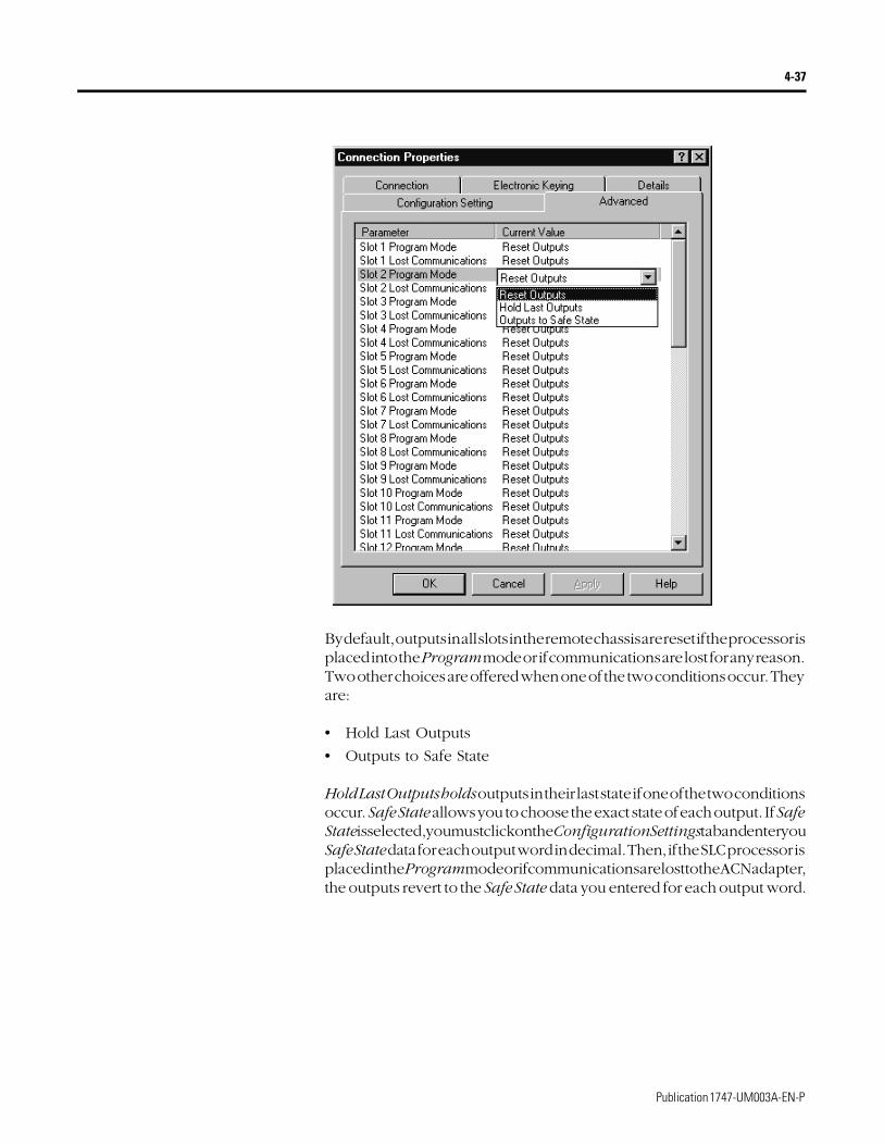
4-37
By default, outputs in all slots in the remote chassis are reset if the processor is placed into the Program mode or if communications are lost for any reason. Two other choices are offered when one of the two conditions occur. They are:
• Hold Last Outputs
• Outputs to Safe State
Hold Last Outputs holds outputs in their last state if one of the two conditions occur. Safe State allows you to choose the exact state of each output. If Safe State is selected, you must click on the Configuration Settings tab and enter you Safe State data for each output word in decimal. Then, if the SLC processor is placed in the Program mode or if communications are lost to the ACN adapter, the outputs revert to the Safe State data you entered for each output word.
Publication 1747-UM003A-EN-P
4-38
Configuring a Module Connection
Next, you need to configure a module connection for the 1746-BAS module. If the previous window is still open, click Apply, then OK to accept the rack connection.
Right click on the 1746-BAS module in the Scanlist Configuration window and select Insert Connection. A Connection Properties window again appears. Choose Exclusive Owner-Advanced for the Connection Name.
In this case, you must choose M-file addresses for this type of connection. The series B Basic module communicates via 8 I/O words and 64 M1 and 64 M0 file words. These Basic module M-file words are independent of the M-file words used to transfer up to 72 words to and from the Basic module. Those 72 M0 and 72 M1 file words reside in the 1747-SCNR and are used to store the data sent to the 1747-ACN15 from the SLC-5/04 processor and to store the data received from the 1747-ACN15 for the SLC-5/04 processor.
The M0 file words in the 1747-SCNR, which are assigned in the Connection Properties screen, are M0:3.3 through M0:3.74. These are the 72 words sent from the SLC-5/04 processor to the 1747-SCNR. Words M1:3.3 through M1:3.74 are the 72 words received from the 1747-ACN15. M-file words M1:3.0 through M1:3.2 and M0:3.0 through M0:3.2 are reserved (refer to the 1747-SCNR User Manual for details). The next available Status Address is M1:3.600/02, since bits 0 and 1 are used for the rack connection. The Connection Properties window for the module connection should look like the following.
Publication 1747-UM003A-EN-P
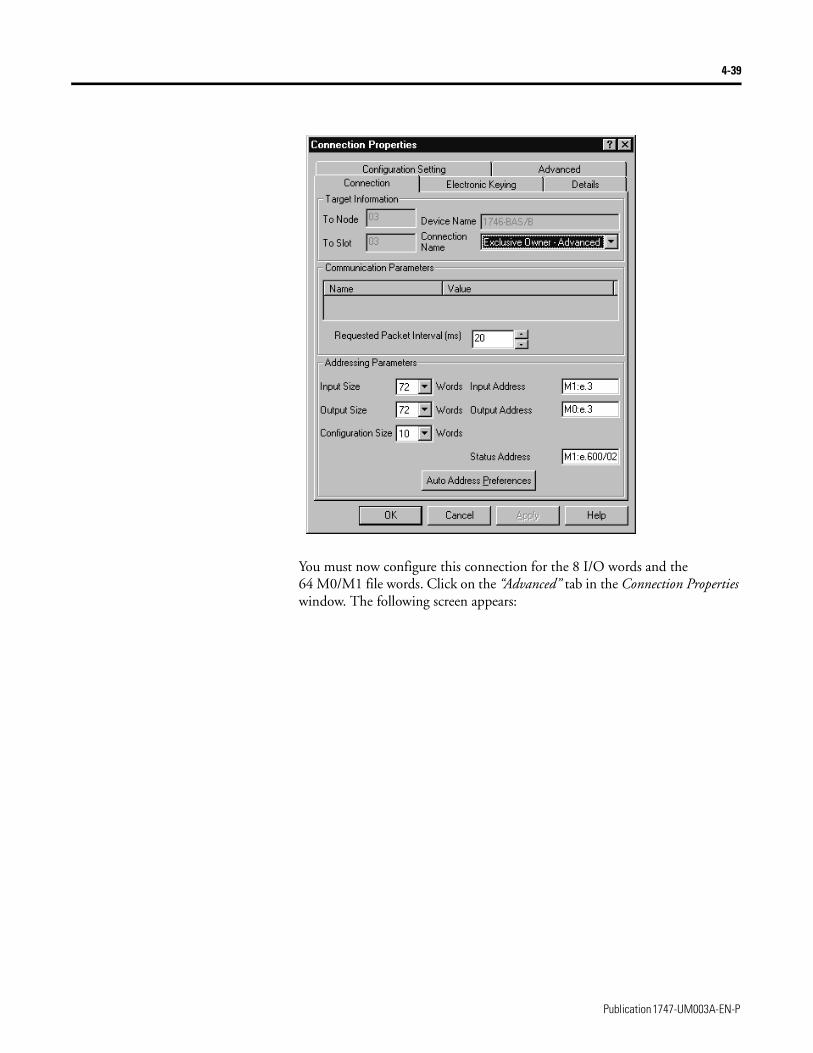
4-39
You must now configure this connection for the 8 I/O words and the 64 M0/M1 file words. Click on the “Advanced” tab in the Connection Properties window. The following screen appears:
Publication 1747-UM003A-EN-P
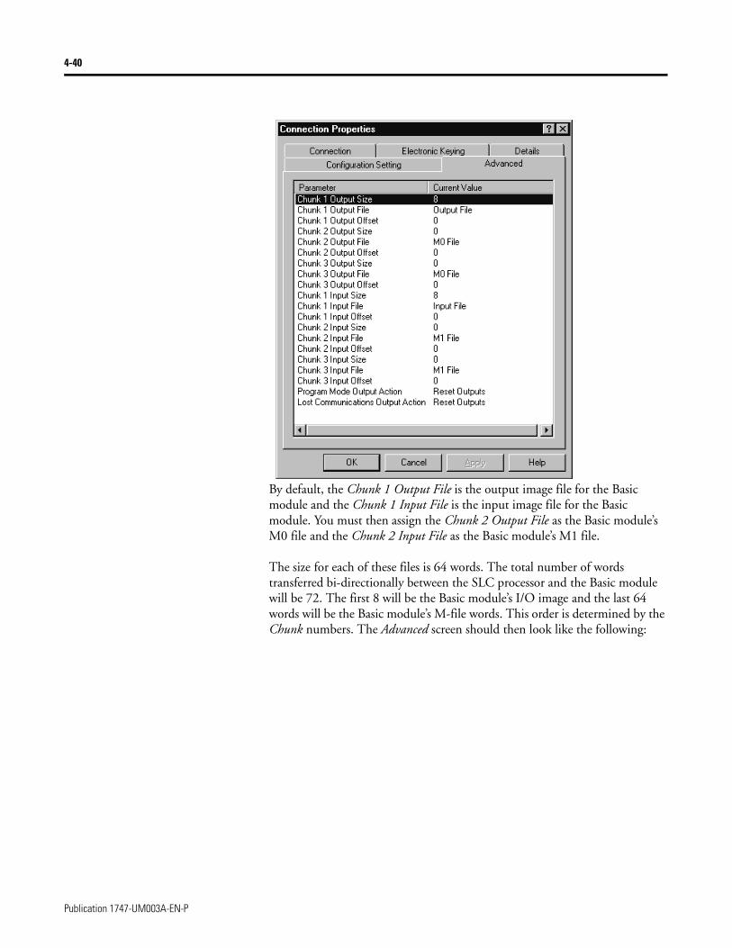
4-40
By default, the Chunk 1 Output File is the output image file for the Basic module and the Chunk 1 Input File is the input image file for the Basic module. You must then assign the Chunk 2 Output File as the Basic module’s M0 file and the Chunk 2 Input File as the Basic module’s M1 file.
The size for each of these files is 64 words. The total number of words transferred bi-directionally between the SLC processor and the Basic module will be 72. The first 8 will be the Basic module’s I/O image and the last 64 words will be the Basic module’s M-file words. This order is determined by the Chunk numbers. The Advanced screen should then look like the following:
Publication 1747-UM003A-EN-P
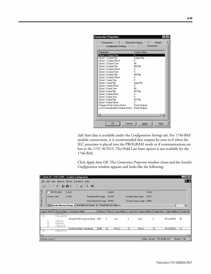
4-41
Safe State data is available under the Configuration Settings tab. For 1746-BAS module connections, it is recommended that outputs be reset to 0 when the SLC processor is placed into the PROGRAM mode or if communications are lost to the 1747-ACN15. The Hold Last State option is not available for the 1746-BAS.
Click Apply, then OK. The Connection Properties window closes and the Scanlist Configuration window appears and looks like the following:
Publication 1747-UM003A-EN-P
4-42
You have now successfully configured your two connections to read/write data between the SLC processor and the remote ControlNet chassis. All that remains is to Save this configuration to the network keeper which, in this case, is the 1747-SCNR.
Click on the Save icon or choose the File pull-down menu and select Save. You are prompted to Optimize and re-write schedule for all connections. Click OK, then click YES to the subsequent warning message. Your network configuration information is then written to the network keeper.
The display on the front of your 1747-SCNR should show a Full Glass next to I/O. This indicates that all configured connections were successfully downloaded to the scanner. In addition, the A and OK LEDs should be solid green and the B LED should be off, unless you are using the redundant media option, which is not being used in this example. The 1747-ACN15 should be displaying that it is active (ACTV) and its LEDs should be solid green for A and OK.
Publication 1747-UM003A-EN-P
4-43
Create Ladder Logic and Basic Module Programs
The final step is to write a ladder program for the SLC processor and a BASIC program for the Basic module. After downloading the program to your processor and to your basic module, place the processor into the RUN mode and run your BASIC program as well. Your programs should now be able to read data from the 1746-IA16 in word I:3.3 and write to the 1746-OB16 in word O:3.2.
The attached BASIC program contains a CALL 23 interrupt CALL for PRT1 and a CALL 22 interrupt CALL for PRT2. The CALL 23 sends data out PRT1 when data is received from the SLC processor and CALL 22 transfers data sent in PRT2 to the SLC. Remember, the first 8 words beginning with M1:3.3 and M0:3.3 are from the Basic module’s Input and Output image. The following 64 words are from the Basic module’s M1 and M0 files. The handshaking required between the SLC processor and the Basic module to transfer data, is shown in the ladder logic program to follow.
Please refer to the 1746-BAS User Manual for a complete description of CALL 22 and 23, as well as the required handshaking. The only difference in the handshake logic when using these Basic module CALLs is that the I/O image words used for the handshaking are stored in the SCNR’s M-files, so they appear as M-file addresses in the ladder logic instead of I/O addresses.
Connect an RS-232 cable between PRT1 and PRT2 on the Basic module. A 1747-CP3 cable works for this purpose. When up to 64 words of data are placed into the SLC processor’s data table beginning at N12:0, it is sent to the 1747-SCNR, then to the Basic module via ControlNet and the 1747-ACN15 and is ultimately sent out PRT1 of the BAS module. If you used a cable to loop the data back in PRT2, this data is sent to the 1747-SCNR via ControlNet and ultimately appears in the SLC processor’s data table beginning with address N13:0.
Note that your ladder program should also contain an unconditional rung with an OTE instruction addressed to the 1747-SCNR scanner’s RUN/IDLE bit, O:3.0/10 for this example. When the SLC processor is placed into the RUN mode, this rung sets the 1747-SCNR scanner’s RUN/IDLE bit and places the scanner into the RUN mode as well. The scanner begins executing the configured connections when the RUN/IDLE bit is set.
Publication 1747-UM003A-EN-P
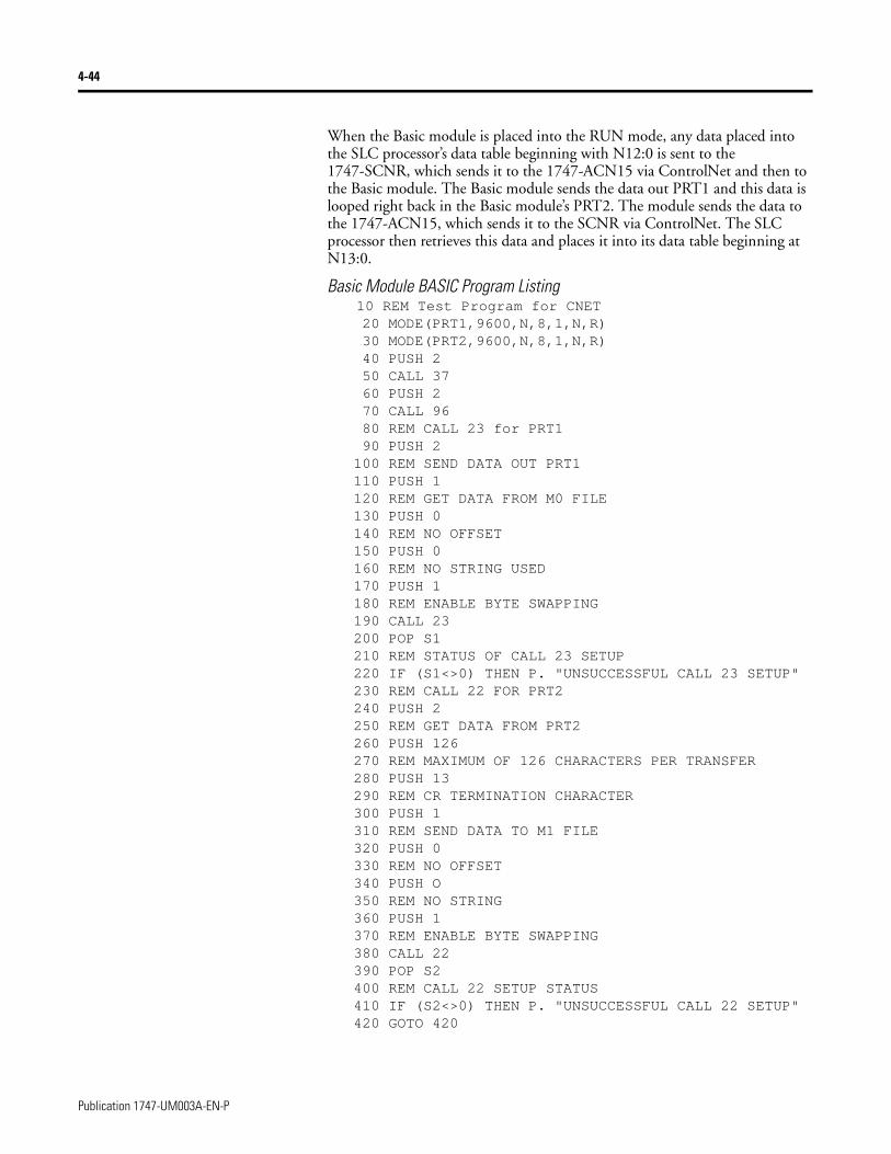
4-44
When the Basic module is placed into the RUN mode, any data placed into the SLC processor’s data table beginning with N12:0 is sent to the 1747-SCNR, which sends it to the 1747-ACN15 via ControlNet and then to the Basic module. The Basic module sends the data out PRT1 and this data is looped right back in the Basic module’s PRT2. The module sends the data to the 1747-ACN15, which sends it to the SCNR via ControlNet. The SLC processor then retrieves this data and places it into its data table beginning at N13:0.
Basic Module BASIC Program Listing10 REM Test Program for CNET20 MODE(PRT1,9600,N,8,1,N,R)30 MODE(PRT2,9600,N,8,1,N,R)40 PUSH 250 CALL 3760 PUSH 270 CALL 9680 REM CALL 23 for PRT190 PUSH 2
100 REM SEND DATA OUT PRT1110 PUSH 1120 REM GET DATA FROM M0 FILE130 PUSH 0140 REM NO OFFSET150 PUSH 0160 REM NO STRING USED170 PUSH 1180 REM ENABLE BYTE SWAPPING190 CALL 23200 POP S1210 REM STATUS OF CALL 23 SETUP220 IF (S1<>0) THEN P. "UNSUCCESSFUL CALL 23 SETUP"230 REM CALL 22 FOR PRT2240 PUSH 2250 REM GET DATA FROM PRT2260 PUSH 126270 REM MAXIMUM OF 126 CHARACTERS PER TRANSFER280 PUSH 13290 REM CR TERMINATION CHARACTER300 PUSH 1310 REM SEND DATA TO M1 FILE320 PUSH 0330 REM NO OFFSET340 PUSH O350 REM NO STRING360 PUSH 1370 REM ENABLE BYTE SWAPPING380 CALL 22390 POP S2400 REM CALL 22 SETUP STATUS410 IF (S2<>0) THEN P. "UNSUCCESSFUL CALL 22 SETUP"420 GOTO 420
Publication 1747-UM003A-EN-P
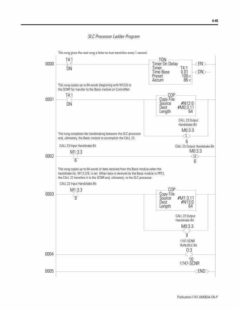
4-45
SLC Processor Ladder Program
0000T4:1
DNEN
DN
TONTimer On DelayTimer T4:1Time Base 0.01Preset 100 <Accum 86 <
0001T4:1
DN
COPCopy FileSource #N12:0Dest #M0:3.11Length 64
L6
0002M1:3.3
6U
M0:3.3
M0:3.3
6
0003M1:3.3
9Copy FileSource #M1:3.11Dest #N13:0Length 64
COP
M0:3.3
9
0004 O:3
101747-SCNR
0005 END
This rung gives the next rung a false-to-true transition every 1 second.
This rung copies up to 64 words (beginning with N12:0) to the SCNR for transfer to the Basic module on ControlNet.
This rung completes the handshaking between the SLC processor and, ultimately, the Basic module to accomplish the CALL 23.
This rung copies up to 64 words of data received from the Basic module when the handshake bit, M1:3.3/9, is set. When data is received by the Basic module in PRT2, the CALL 22 transfers it to the SCNR and, ultimately, to the SLC processor.
CALL 23 Input Handshake Bit
CALL 22 Input Handshake Bit
CALL 23 Output Handshake Bit
CALL 22 Output Handshake Bit
1747-SCNR RUN/IDLE Bit
CALL 23 Output Handshake Bit
Publication 1747-UM003A-EN-P
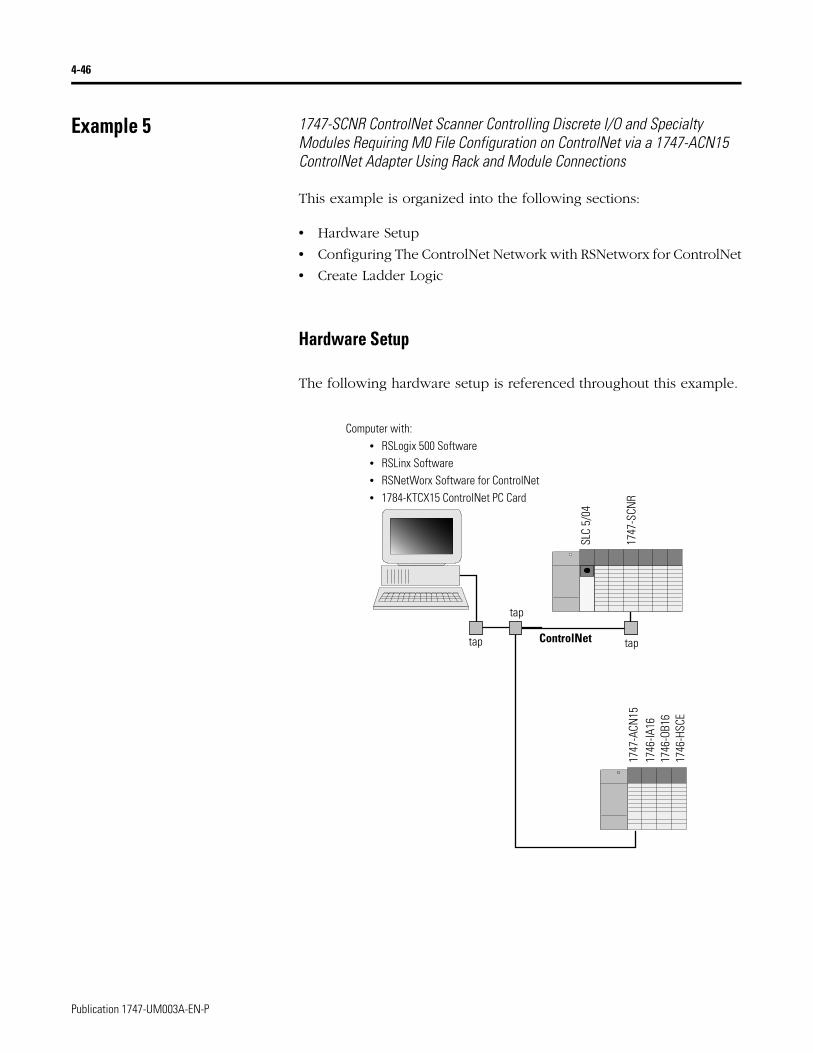
4-46
Example 5 1747-SCNR ControlNet Scanner Controlling Discrete I/O and Specialty Modules Requiring M0 File Configuration on ControlNet via a 1747-ACN15 ControlNet Adapter Using Rack and Module Connections
This example is organized into the following sections:
• Hardware Setup
• Configuring The ControlNet Network with RSNetworx for ControlNet
• Create Ladder Logic
Hardware Setup
The following hardware setup is referenced throughout this example.
ControlNet
Computer with:• RSLogix 500 Software• RSLinx Software• RSNetWorx Software for ControlNet• 1784-KTCX15 ControlNet PC Card
tap
tap
SLC
5/04
1747
-SCN
R17
47-A
CN15
1746
-IA16
1746
-OB1
617
46-H
SCE
tap
Publication 1747-UM003A-EN-P
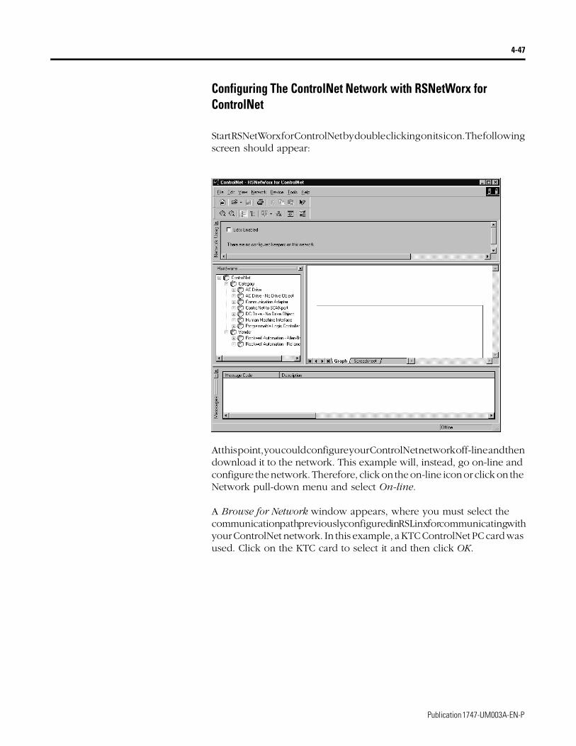
4-47
Configuring The ControlNet Network with RSNetWorx for ControlNet
Start RSNetWorx for ControlNet by double clicking on its icon. The following screen should appear:
At this point, you could configure your ControlNet network off-line and then download it to the network. This example will, instead, go on-line and configure the network. Therefore, click on the on-line icon or click on the Network pull-down menu and select On-line.
A Browse for Network window appears, where you must select the communication path previously configured in RSLinx for communicating with your ControlNet network. In this example, a KTC ControlNet PC card was used. Click on the KTC card to select it and then click OK.
Publication 1747-UM003A-EN-P

4-48
The software attempts to communicate with all possible node numbers on the network, from 1 to 99. Click on the Edits Enabled box allow changes to be made. For this example, the on-line network screen should look like the following, where node 99 is the programming terminal.
Node 1 is the 1747-SCNR and node 3 is the 1747-ACN15. The 1747-ACN15 resides in slot 0 of its chassis, while slot 1 contains a 1746-IA16, slot 2 contains a 1746-OB16, and slot 3 contains a 1746-HSCE. For this example, 2 separate ControlNet connections are configured. The first is a Discrete 16 Bit Exclusive Owner rack connection for the 2 discrete I/O modules and the second is an Exclusive Owner Advanced (module connection) to the 1746-HSCE high speed counter module.
Before creating these necessary connections, verify the chassis configuration for the 1747-ACN15 chassis. To do this, right click on the 1747-ACN15, then choose Edit Chassis. Verify that the chassis configuration is as follows:
slot 0: 1747-ACNR15slot 1: 1746-IA16slot 2: 1746-OB16slot 3: 1746-HSCE
If the chassis is not already configured, manually configure it by dragging the appropriate modules from the list on the right to the proper slot on the left of the chassis configuration screen. When on-line, the software reads the module types for you. When this is complete, click Apply, then OK.
Publication 1747-UM003A-EN-P
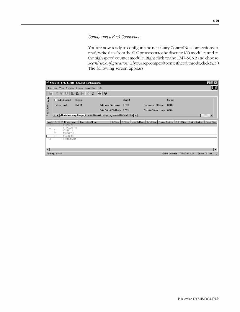
4-49
Configuring a Rack Connection
You are now ready to configure the necessary ControlNet connections to read/write data from the SLC processor to the discrete I/O modules and to the high speed counter module. Right click on the 1747-SCNR and choose Scanlist Configuration. (If you are prompted to enter the edit mode, click YES.) The following screen appears:
Publication 1747-UM003A-EN-P
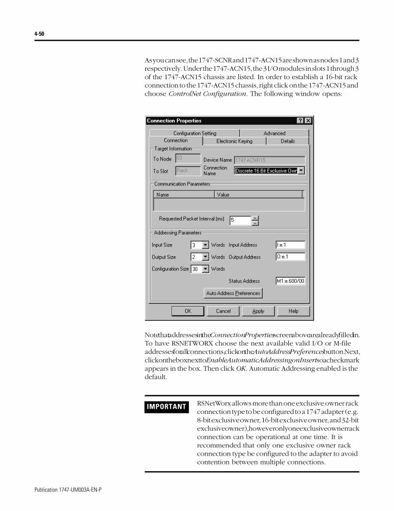
4-50
As you can see, the 1747-SCNR and 1747-ACN15 are shown as nodes 1 and 3 respectively. Under the 1747-ACN15, the 3 I/O modules in slots 1 through 3 of the 1747-ACN15 chassis are listed. In order to establish a 16-bit rack connection to the 1747-ACN15 chassis, right click on the 1747-ACN15 and choose ControlNet Configuration. The following window opens:
Note that addresses in the Connection Properties screen above are already filled in. To have RSNETWORX choose the next available valid I/O or M-file addresses for all connections, click on the Auto Address Preferences button. Next, click on the box next to Enable Automatic Addressing on Insert so a check mark appears in the box. Then click OK. Automatic Addressing enabled is the default.
IMPORTANT RSNetWorx allows more than one exclusive owner rack connection type to be configured to a 1747 adapter (e.g. 8-bit exclusive owner, 16-bit exclusive owner, and 32-bit exclusive owner), however only one exclusive owner rack connection can be operational at one time. It is recommended that only one exclusive owner rack connection type be configured to the adapter to avoid contention between multiple connections.
Publication 1747-UM003A-EN-P
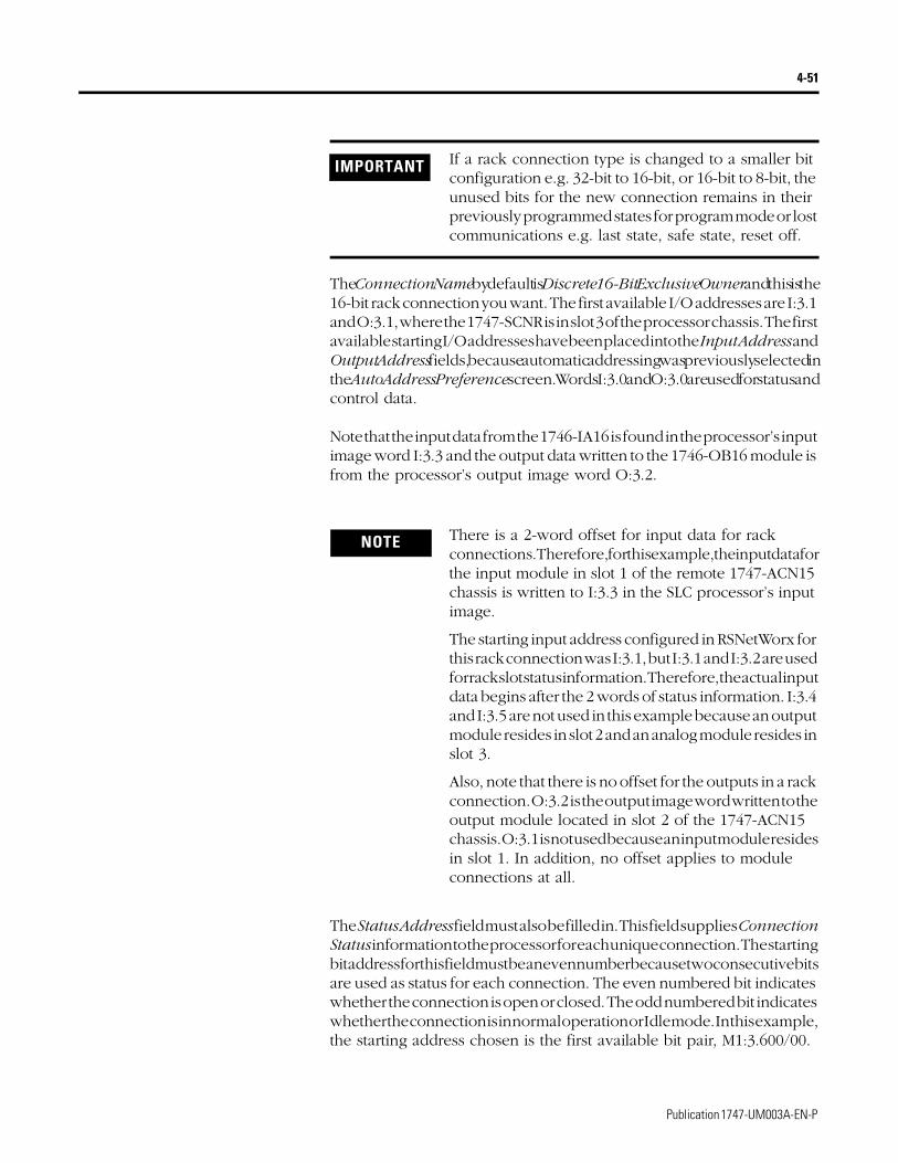
4-51
The Connection Name by default is Discrete 16-Bit Exclusive Owner and this is the 16-bit rack connection you want. The first available I/O addresses are I:3.1 and O:3.1, where the 1747-SCNR is in slot 3 of the processor chassis. The first available starting I/O addresses have been placed into the Input Address and Output Address fields, because automatic addressing was previously selected in the Auto Address Preference screen. Words I:3.0 and O:3.0 are used for status and control data.
Note that the input data from the 1746-IA16 is found in the processor’s input image word I:3.3 and the output data written to the 1746-OB16 module is from the processor’s output image word O:3.2.
The Status Address field must also be filled in. This field supplies Connection Status information to the processor for each unique connection. The starting bit address for this field must be an even number because two consecutive bits are used as status for each connection. The even numbered bit indicates whether the connection is open or closed. The odd numbered bit indicates whether the connection is in normal operation or Idle mode. In this example, the starting address chosen is the first available bit pair, M1:3.600/00.
IMPORTANT If a rack connection type is changed to a smaller bit configuration e.g. 32-bit to 16-bit, or 16-bit to 8-bit, the unused bits for the new connection remains in their previously programmed states for program mode or lost communications e.g. last state, safe state, reset off.
NOTE There is a 2-word offset for input data for rack connections. Therefore, for this example, the input data for the input module in slot 1 of the remote 1747-ACN15 chassis is written to I:3.3 in the SLC processor’s input image.
The starting input address configured in RSNetWorx for this rack connection was I:3.1, but I:3.1 and I:3.2 are used for rack slot status information. Therefore, the actual input data begins after the 2 words of status information. I:3.4 and I:3.5 are not used in this example because an output module resides in slot 2 and an analog module resides in slot 3.
Also, note that there is no offset for the outputs in a rack connection. O:3.2 is the output image word written to the output module located in slot 2 of the 1747-ACN15 chassis. O:3.1 is not used because an input module resides in slot 1. In addition, no offset applies to module connections at all.
Publication 1747-UM003A-EN-P
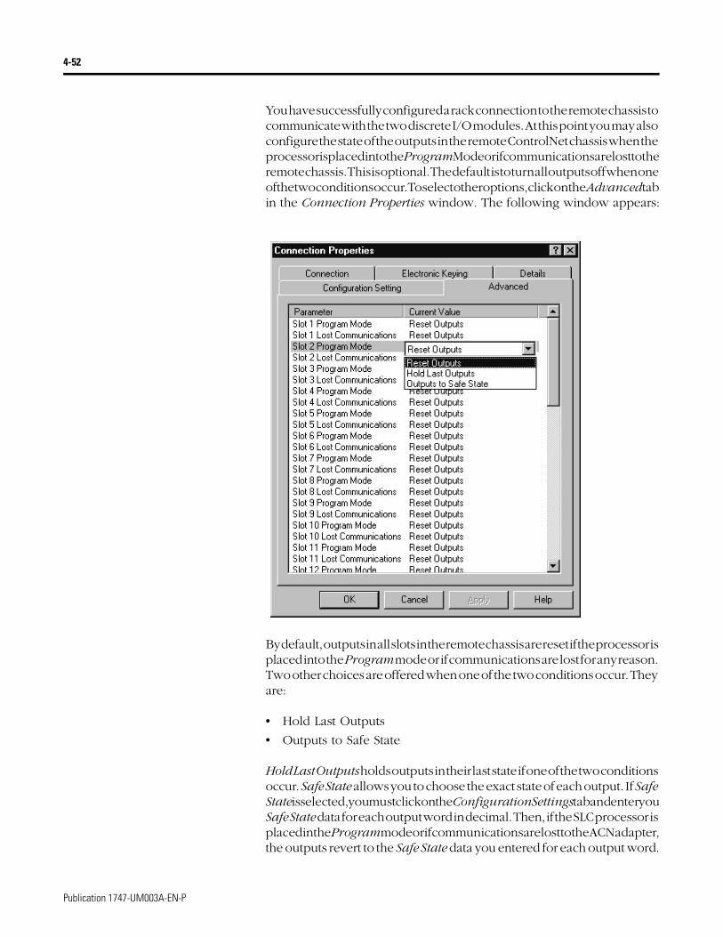
4-52
You have successfully configured a rack connection to the remote chassis to communicate with the two discrete I/O modules. At this point you may also configure the state of the outputs in the remote ControlNet chassis when the processor is placed into the Program Mode or if communications are lost to the remote chassis. This is optional. The default is to turn all outputs off when one of the two conditions occur. To select other options, click on the Advanced tab in the Connection Properties window. The following window appears:
By default, outputs in all slots in the remote chassis are reset if the processor is placed into the Program mode or if communications are lost for any reason. Two other choices are offered when one of the two conditions occur. They are:
• Hold Last Outputs
• Outputs to Safe State
Hold Last Outputs holds outputs in their last state if one of the two conditions occur. Safe State allows you to choose the exact state of each output. If Safe State is selected, you must click on the Configuration Settings tab and enter you Safe State data for each output word in decimal. Then, if the SLC processor is placed in the Program mode or if communications are lost to the ACN adapter, the outputs revert to the Safe State data you entered for each output word.
Publication 1747-UM003A-EN-P

4-53
Configuring a Module Connection
Next, you need to configure a module connection for the 1746-HSCE high speed counter module. If the previous window is still open, click Apply, then OK to accept the rack connection.
Right click on the 1746-HSCE module in the Scanlist Configuration window and select Insert Connection. A Connection Properties window again appears. Choose Exclusive Owner Advanced for the Connection Name.
In this case choose M-file addresses for the high speed counter module. It requires 1 output word and 8 input words. M-file words are used for this in the 1747-SCNR. M0:3.3 is used for the output word. M1:3.3 through M1:3.10 are used for the input information. Refer to your 1746-HSCE User’s Manual for additional information on this module.
M-file words M1:3.0 through M1:3.2 and M0:3.0 through M0:3.2 are reserved (refer to the 1747-SCNR User Manual for details). The next available Status Address is M1:3.600/02 since bits 0 and 1 are used for the rack connection. The Connection Properties window for the module connection should look like the following.
Publication 1747-UM003A-EN-P
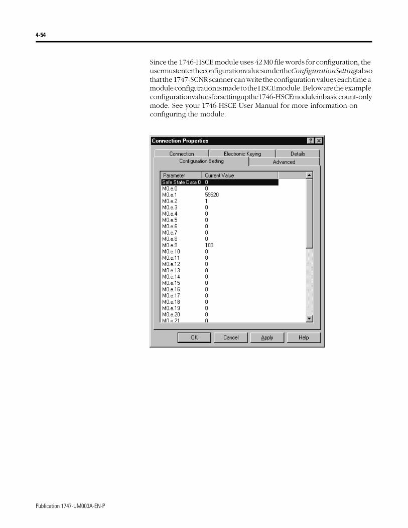
4-54
Since the 1746-HSCE module uses 42 M0 file words for configuration, the user must enter the configuration values under the Configuration Setting tab so that the 1747-SCNR scanner can write the configuration values each time a module configuration is made to the HSCE module. Below are the example configuration values for setting up the 1746-HSCE module in basic count-only mode. See your 1746-HSCE User Manual for more information on configuring the module.
Publication 1747-UM003A-EN-P
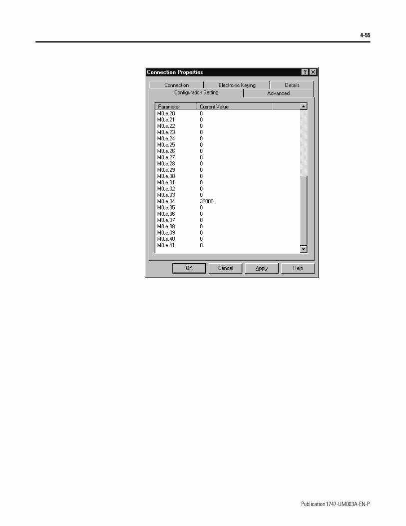
4-55
Publication 1747-UM003A-EN-P
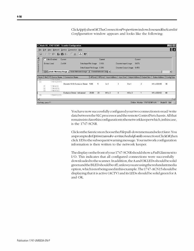
4-56
Click Apply, then OK. The Connection Properties window closes and the Scanlist Configuration window appears and looks like the following:
You have now successfully configured your two connections to read/write data between the SLC processor and the remote ControlNet chassis. All that remains is to Save this configuration to the network keeper which, in this case, is the 1747-SCNR.
Click on the Save icon or choose the File pull-down menu and select Save. You are prompted to Optimize and re-write schedule for all connections. Click OK, then click YES to the subsequent warning message. Your network configuration information is then written to the network keeper.
The display on the front of your 1747-SCNR should show a Full Glass next to I/O. This indicates that all configured connections were successfully downloaded to the scanner. In addition, the A and OK LEDs should be solid green and the B LED should be off, unless you are using the redundant media option, which is not being used in this example. The 1747-ACN15 should be displaying that it is active (ACTV) and its LEDs should be solid green for A and OK.
Publication 1747-UM003A-EN-P
4-57
Create a Ladder Logic Program
The final step is to write a ladder program for the SLC processor, including configuring the 1747-SCNR for slot 3 of the processor’s chassis. After downloading the program to your processor, place it into the RUN mode. Your program should now be able to read data from the 1746-IA16 in word I:3.3 and write to the 1746-OB16 in word O:3.2. The HSCE input data will reside in words M1:3.3 through M1:3.18, while the HSCE module output data must be copied to word M0:3.3.
Note that your ladder program should also contain an unconditional rung with an OTE instruction addressed to the SCNR scanner’s RUN/IDLE bit, O:3.0/10 for this example. When the SLC processor is placed into the RUN mode, this rung sets the SCNR scanner’s RUN/IDLE bit and places the scanner into the RUN mode as well. The scanner begins executing the configured connections when the RUN/IDLE bit is set.
Publication 1747-UM003A-EN-P

4-58
Publication 1747-UM003A-EN-P
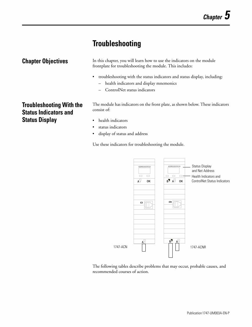
Chapter 5
Troubleshooting
Chapter Objectives In this chapter, you will learn how to use the indicators on the module frontplate for troubleshooting the module. This includes:
• troubleshooting with the status indicators and status display, including:
– health indicators and display mnemonics
– ControlNet status indicators
Troubleshooting With the Status Indicators and Status Display
The module has indicators on the front plate, as shown below. These indicators consist of:
• health indicators
• status indicators
• display of status and address
Use these indicators for troubleshooting the module.
The following tables describe problems that may occur, probable causes, and recommended courses of action.
ADDRESS/STATUS ADDRESS/STATUS
BA A
A AB
OK OK
Status Display and Net Address
Health Indicators andControlNet Status Indicators
1747-ACN 1747-ACNR
1 Publication 1747-UM003A-EN-P
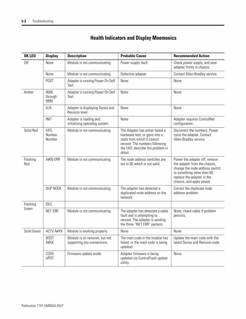
5-2 Troubleshooting
Health Indicators and Display Mnemonics
OK LED Display Description Probable Cause Recommended Action
Off None Module is not communicating. Power supply fault. Check power supply, and seat adapter firmly in chassis.
None Module is not communicating. Defective adapter. Contact Allen-Bradley service.
POST Adapter is running Power On Self Test.
None None
Amber 0000 through 9999
Adapter is running Power On Self Test.
None None
A/A Adapter is displaying Series and Revision level.
None None
INIT Adapter is loading and initializing operating system.
None Adapter requires ControlNet configuration.
Solid Red FATL Number Number
Module is not communicating. The Adapter has either failed a hardware test, or gone into a state from which it cannot recover. The numbers following the FATL describe the problem in detail.
Document the numbers. Power cycle the adapter. Contact Allen-Bradley service.
Flashing Red
A#00 ERR Module is not communicating. The node address switches are set to 00 which is not valid.
Power the adapter off, remove the adapter from the chassis, change the node address switch to something other than 00, replace the adapter in the chassis, and apply power.
DUP NODE Module is not communicating. The adapter has detected a duplicated node address on the network.
Correct the duplicate node address problem.
Flashing Green
IDLE
NET ERR Module is not communicating. The adapter has detected a cable fault and is attempting to recover. The adapter is sending the three “NET ERR” packets.
None, check cable if problem persists.
Solid Green ACTV A#XX Module is working properly. None None
BOOT A#XX
Module is on network, but not supporting any connections.
The main code in the module has failed, or the main code is being updated.
Update the main code with the latest Series and Revision code.
CODE UPDT
Firmware update mode. Adapter firmware is being updated via ControlFlash update utility.
None
Publication 1747-UM003A-EN-P
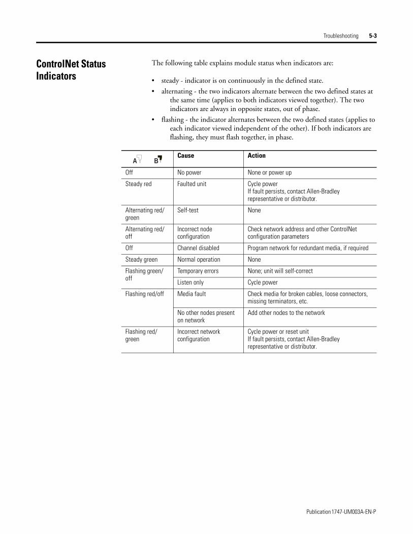
Troubleshooting 5-3
ControlNet Status Indicators
The following table explains module status when indicators are:
• steady - indicator is on continuously in the defined state.
• alternating - the two indicators alternate between the two defined states at the same time (applies to both indicators viewed together). The two indicators are always in opposite states, out of phase.
• flashing - the indicator alternates between the two defined states (applies to each indicator viewed independent of the other). If both indicators are flashing, they must flash together, in phase.
Cause Action
Off No power None or power up
Steady red Faulted unit Cycle powerIf fault persists, contact Allen-Bradley representative or distributor.
Alternating red/green
Self-test None
Alternating red/off
Incorrect node configuration
Check network address and other ControlNet configuration parameters
Off Channel disabled Program network for redundant media, if required
Steady green Normal operation None
Flashing green/off
Temporary errors None; unit will self-correct
Listen only Cycle power
Flashing red/off Media fault Check media for broken cables, loose connectors, missing terminators, etc.
No other nodes present on network
Add other nodes to the network
Flashing red/green
Incorrect network configuration
Cycle power or reset unitIf fault persists, contact Allen-Bradley representative or distributor.
BA
Publication 1747-UM003A-EN-P

5-4 Troubleshooting
Publication 1747-UM003A-EN-P
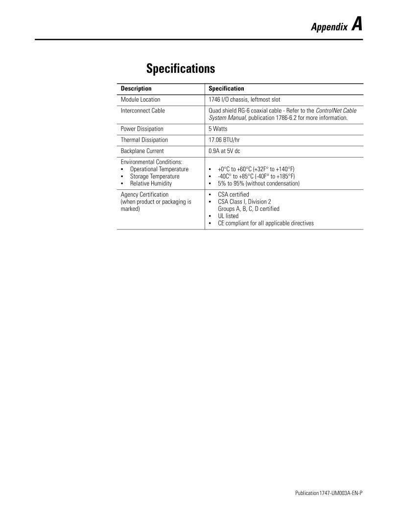
Appendix A
SpecificationsDescription Specification
Module Location 1746 I/O chassis, leftmost slot
Interconnect Cable Quad shield RG-6 coaxial cable - Refer to the ControlNet Cable System Manual, publication 1786-6.2 for more information.
Power Dissipation 5 Watts
Thermal Dissipation 17.06 BTU/hr
Backplane Current 0.9A at 5V dc
Environmental Conditions:• Operational Temperature• Storage Temperature• Relative Humidity
• +0°C to +60°C (+32F° to +140°F)• -40C° to +85°C (-40F° to +185°F)• 5% to 95% (without condensation)
Agency Certification(when product or packaging is marked)
• CSA certified• CSA Class I, Division 2
Groups A, B, C, D certified• UL listed• CE compliant for all applicable directives
1 Publication 1747-UM003A-EN-P

A-2 Specifications
Publication 1747-UM003A-EN-P
1747-UM003A-US-P
Appendix B
Understanding Your SLC 500/1746 Control SystemThis appendix provides information on using SLC 500/1746 control systems. Topics include:
• selecting your SLC 500/1746 control power supply
• system installation recommendations
• mounting your control system
• installing your I/O modules
• wiring the I/O modules
• calculating heat dissipation for your control system
When configuring a modular system, you must have an individual power supply for each chassis. Careful system configuration results in the best performance. Excessive loading of the power supply outputs can cause a power supply shutdown or premature failure.
Selecting Your SLC 500/1746 Control Power Supply
There are three different ac power supplies and four dc power supplies. For ac power supplies, the 120/240V selection is made by a jumper. Place the jumper to match the input voltage. The power supply has an LED that illuminates when the power supply is functioning properly. On the following page are the general specifications for the power supplies.
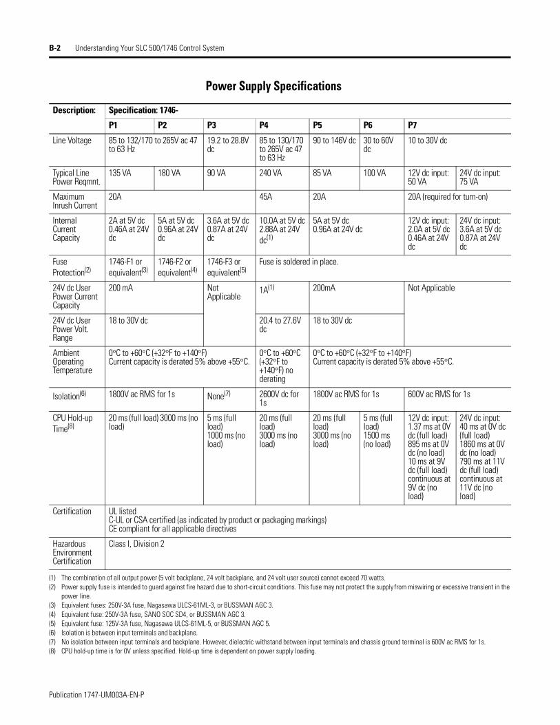
B-2 Understanding Your SLC 500/1746 Control System
Power Supply Specifications
Description: Specification: 1746-
P1 P2 P3 P4 P5 P6 P7
Line Voltage 85 to 132/170 to 265V ac 47 to 63 Hz
19.2 to 28.8V dc
85 to 130/170 to 265V ac 47 to 63 Hz
90 to 146V dc 30 to 60V dc
10 to 30V dc
Typical Line Power Reqmnt.
135 VA 180 VA 90 VA 240 VA 85 VA 100 VA 12V dc input: 50 VA
24V dc input: 75 VA
Maximum Inrush Current
20A 45A 20A 20A (required for turn-on)
Internal Current Capacity
2A at 5V dc0.46A at 24V dc
5A at 5V dc0.96A at 24V dc
3.6A at 5V dc0.87A at 24V dc
10.0A at 5V dc2.88A at 24V dc(1)
5A at 5V dc0.96A at 24V dc
12V dc input:2.0A at 5V dc 0.46A at 24V dc
24V dc input: 3.6A at 5V dc 0.87A at 24V dc
Fuse Protection(2)
1746-F1 or equivalent(3)
1746-F2 or equivalent(4)
1746-F3 or equivalent(5)
Fuse is soldered in place.
24V dc User Power Current Capacity
200 mA Not Applicable
1A(1) 200mA Not Applicable
24V dc User Power Volt. Range
18 to 30V dc 20.4 to 27.6V dc
18 to 30V dc
Ambient Operating Temperature
0°C to +60°C (+32°F to +140°F)Current capacity is derated 5% above +55°C.
0°C to +60°C (+32°F to +140°F) no derating
0°C to +60°C (+32°F to +140°F)Current capacity is derated 5% above +55°C.
Isolation(6) 1800V ac RMS for 1s None(7) 2600V dc for 1s
1800V ac RMS for 1s 600V ac RMS for 1s
CPU Hold-up Time(8)
20 ms (full load) 3000 ms (no load)
5 ms (full load) 1000 ms (no load)
20 ms (full load) 3000 ms (no load)
20 ms (full load)3000 ms (no load)
5 ms (full load)1500 ms (no load)
12V dc input: 1.37 ms at 0V dc (full load)895 ms at 0V dc (no load)10 ms at 9V dc (full load)continuous at 9V dc (no load)
24V dc input: 40 ms at 0V dc (full load)1860 ms at 0V dc (no load)790 ms at 11V dc (full load)continuous at 11V dc (no load)
Certification UL listedC-UL or CSA certified (as indicated by product or packaging markings)CE compliant for all applicable directives
Hazardous Environment Certification
Class I, Division 2
(1) The combination of all output power (5 volt backplane, 24 volt backplane, and 24 volt user source) cannot exceed 70 watts.(2) Power supply fuse is intended to guard against fire hazard due to short-circuit conditions. This fuse may not protect the supply from miswiring or excessive transient in the
power line.(3) Equivalent fuses: 250V-3A fuse, Nagasawa ULCS-61ML-3, or BUSSMAN AGC 3.(4) Equivalent fuse: 250V-3A fuse, SANO SOC SD4, or BUSSMAN AGC 3.(5) Equivalent fuse: 125V-3A fuse, Nagasawa ULCS-61ML-5, or BUSSMAN AGC 5.(6) Isolation is between input terminals and backplane.(7) No isolation between input terminals and backplane. However, dielectric withstand between input terminals and chassis ground terminal is 600V ac RMS for 1s.(8) CPU hold-up time is for 0V unless specified. Hold-up time is dependent on power supply loading.
Publication 1747-UM003A-EN-P
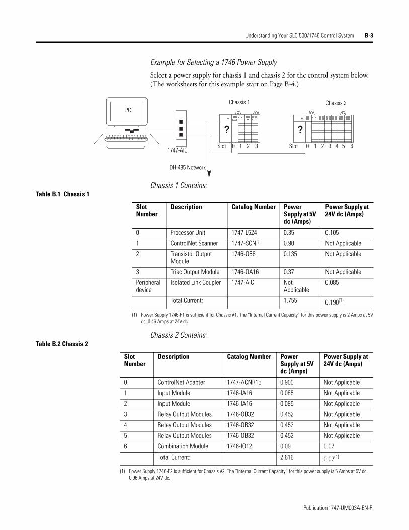
Understanding Your SLC 500/1746 Control System B-3
Example for Selecting a 1746 Power SupplySelect a power supply for chassis 1 and chassis 2 for the control system below. (The worksheets for this example start on Page B-4.)
Chassis 1 Contains:
Chassis 2 Contains:
? ?
PC
1747-AIC
DH-485 Network
Chassis 1 Chassis 2
Slot Slot 0 1 2 3 0 1 2 3 4 5 6
Table B.1 Chassis 1
Slot Number
Description Catalog Number Power Supply at 5V dc (Amps)
Power Supply at 24V dc (Amps)
0 Processor Unit 1747-L524 0.35 0.105
1 ControlNet Scanner 1747-SCNR 0.90 Not Applicable
2 Transistor Output Module
1746-OB8 0.135 Not Applicable
3 Triac Output Module 1746-OA16 0.37 Not Applicable
Peripheral device
Isolated Link Coupler 1747-AIC Not Applicable
0.085
Total Current: 1.755 0.190(1)
(1) Power Supply 1746-P1 is sufficient for Chassis #1. The “Internal Current Capacity” for this power supply is 2 Amps at 5V dc, 0.46 Amps at 24V dc.
Table B.2 Chassis 2
Slot Number
Description Catalog Number Power Supply at 5V dc (Amps)
Power Supply at 24V dc (Amps)
0 ControlNet Adapter 1747-ACNR15 0.900 Not Applicable
1 Input Module 1746-IA16 0.085 Not Applicable
2 Input Module 1746-IA16 0.085 Not Applicable
3 Relay Output Modules 1746-OB32 0.452 Not Applicable
4 Relay Output Modules 1746-OB32 0.452 Not Applicable
5 Relay Output Modules 1746-OB32 0.452 Not Applicable
6 Combination Module 1746-IO12 0.09 0.07
Total Current: 2.616 0.07(1)
(1) Power Supply 1746-P2 is sufficient for Chassis #2. The “Internal Current Capacity” for this power supply is 5 Amps at 5V dc, 0.96 Amps at 24V dc.
Publication 1747-UM003A-EN-P
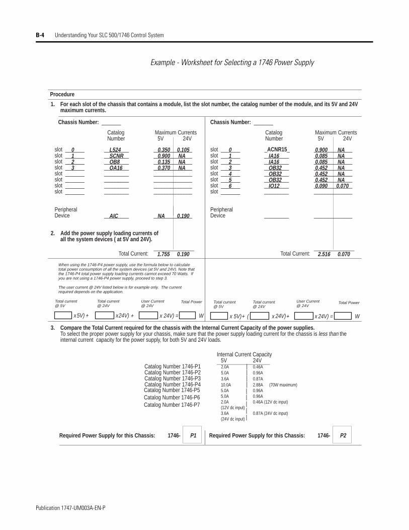
B-4 Understanding Your SLC 500/1746 Control System
Example - Worksheet for Selecting a 1746 Power Supply
0.1901.755
________________________________________________________________________________________________________________
______________
slot _______slot _______slot _______slot _______slot _______slot _______slot _______slot _______
PeripheralDevice
________________________________________________________________________
_________
________________________________________________________________________________________________________________
______________
0123456
IA16IA16OB32OB32OB32IO12
0.9000.0850.0850.4520.4520.4520.090
L524SCNROB8OA16
AIC
0.105 NA NA NA
0.190
0.3500.9000.1350.370
NA
Procedure
Required Power Supply for this Chassis: 1746- P1
1. For each slot of the chassis that contains a module, list the slot number, the catalog number of the module, and its 5V and 2 4V maximum currents.
Chassis Number: _______ Chassis Number: _______
CatalogNumber
Maximum Currents 5V 24V
2. Add the power supply loading currents of all the system devices ( at 5V and 24V).
___________
3. Compare the Total Current required for the chassis with the Internal Current Capacity of the power supplies.To select the proper power supply for your chassis, make sure that the power supply loading current for the chassis is less than the internal current capacity for the power supply, for both 5V and 24V loads.
Internal Current Capacity 5V 24V
Catalog Number 1746-P1 2.0A | 0.46ACatalog Number 1746-P2 5.0A | 0.96ACatalog Number 1746-P3 3.6A | 0.87ACatalog Number 1746-P4 10.0A
5.0A5.0A2.0A (12V dc input)3.6A(24V dc input)
| 2.88A0.96A0.96A0.46A (12V dc input)
0.87A (24V dc input)
(70W maximum)
Required Power Supply for this Chassis: 1746- P2
slot _______slot _______slot _______slot _______slot _______slot _______slot _______slot _______
PeripheralDevice
CatalogNumber
Maximum Currents 5V 24V
_______________________________________________________________
_________
0123
Total Power
Total Current:
When using the 1746-P4 power supply, use the formula below to calculatetotal power consumption of all the system devices (at 5V and 24V). Note thatthe 1746-P4 total power supply loading currents cannot exceed 70 Watts. Ifyou are not using a 1746-P4 power supply, proceed to step 3.
Total Current:
Total current@ 5V
Total current@ 24V
Total PowerTotal current@ 5V
Total current@ 24V
User Current@ 24V
The user current @ 24V listed below is for example only. The currentrequired depends on the application.
User Current@ 24V
24V) = W +24V)x5V)xx5V) + x24V) + (+ x x 24V) = W
NA NA NA NA NA NA0.070
0.0702.516___________
_ACNR15_
Catalog Number 1746-P5Catalog Number 1746-P6Catalog Number 1746-P7
|
||||
Publication 1747-UM003A-EN-P
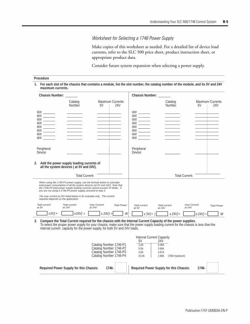
Understanding Your SLC 500/1746 Control System B-5
Worksheet for Selecting a 1746 Power Supply
Make copies of this worksheet as needed. For a detailed list of device load currents, refer to the SLC 500 price sheet, product instruction sheet, or appropriate product data.
Consider future system expansion when selecting a power supply.
________________________________________________________________________
_________
slot _______slot _______slot _______slot _______slot _______slot _______slot _______slot _______
PeripheralDevice
________________________________________________________________________________________________________________
______________
slot _______slot _______slot _______slot _______slot _______slot _______slot _______slot _______
PeripheralDevice
________________________________________________________________________
_________
________________________________________________________________________________________________________________
______________
Procedure
Required Power Supply for this Chassis: 1746-
1. For each slot of the chassis that contains a module, list the slot number, the catalog number of the module, and its 5V and 2 4V maximum currents.
Chassis Number: _______ Chassis Number: _______
CatalogNumber
Maximum Currents 5V 24V
2. Add the power supply loading currents of all the system devices ( at 5V and 24V).
___________
3. Compare the Total Current required for the chassis with the Internal Current Capacity of the power supplies.To select the proper power supply for your chassis, make sure that the power supply loading current for the chassis is less than the internal current capacity for the power supply, for both 5V and 24V loads.
Internal Current Capacity 5V 24V
Catalog Number 1746-P1 2.0A | 0.46ACatalog Number 1746-P2 5.0A | 0.96ACatalog Number 1746-P3 3.6A | 0.87ACatalog Number 1746-P4 10.0A | 2.88A (70W maximum)
Required Power Supply for this Chassis: 1746-
CatalogNumber
Maximum Currents 5V 24V
Total Power
Total Current:
When using the 1746-P4 power supply, use the formula below to calculatetotal power consumption of all the system devices (at 5V and 24V). Note thatthe 1746-P4 total power supply loading currents cannot exceed 70 Watts. Ifyou are not using a 1746-P4 power supply, proceed to step 3.
Total Current:
Total currentat 5V
Total currentat 24V
Total PowerTotal currentat 5V
Total currentat 24V
User Currentat 24V
The user current at 24V listed below is for example only . The currentrequired depends on the application.
User Currentat 24V
24V) = W +24V)x5V)xx5V) + x24V) + (+ x x 24V) = W
___________
Publication 1747-UM003A-EN-P
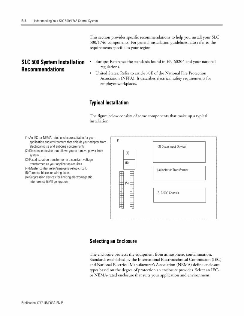
B-6 Understanding Your SLC 500/1746 Control System
This section provides specific recommendations to help you install your SLC 500/1746 components. For general installation guidelines, also refer to the requirements specific to your region.
SLC 500 System Installation Recommendations
• Europe: Reference the standards found in EN 60204 and your national regulations.
• United States: Refer to article 70E of the National Fire Protection Association (NFPA). It describes electrical safety requirements for employee workplaces.
Typical Installation
The figure below consists of some components that make up a typical installation.
Selecting an Enclosure
The enclosure protects the equipment from atmospheric contamination. Standards established by the International Electrotechnical Commission (IEC) and National Electrical Manufacturer’s Association (NEMA) define enclosure types based on the degree of protection an enclosure provides. Select an IEC- or NEMA-rated enclosure that suits your application and environment.
(2) Disconnect Device
(3) Isolation Transformer
SLC 500 Chassis
(1) An IEC- or NEMA-rated enclosure suitable for your application and environment that shields your adapter from electrical noise and airborne contaminants.
(2) Disconnect device that allows you to remove power from system.
(3) Fused isolation transformer or a constant voltage transformer, as your application requires.
(4) Master control relay/emergency-stop circuit.(5) Terminal blocks or wiring ducts.(6) Suppression devices for limiting electromagnetic
interference (EMI) generation.
(1)
(4)
(6)
(5)
Publication 1747-UM003A-EN-P
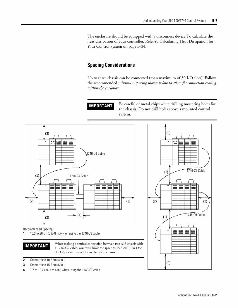
Understanding Your SLC 500/1746 Control System B-7
The enclosure should be equipped with a disconnect device. To calculate the heat dissipation of your controller, Refer to Calculating Heat Dissipation for Your Control System on page B-34.
Spacing Considerations
Up to three chassis can be connected (for a maximum of 30 I/O slots). Follow the recommended minimum spacing shown below to allow for convection cooling within the enclosure.
IMPORTANT Be careful of metal chips when drilling mounting holes for the chassis. Do not drill holes above a mounted control system.
(1)
(2)
(3)(4)
(3)
(2)
(1)
(1)
(2)(2)
(3)
(3)
Recommended Spacing:1. 15.3 to 20 cm (6 to 8 in.) when using the 1746-C9 cable.
2. Greater than 10.2 cm (4 in.).3. Greater than 15.3 cm (6 in.).4. 7.7 to 10.2 cm (3 to 4 in.) when using the 1746-C7 cable.
IMPORTANTWhen making a vertical connection between two A13 chassis with a 1746-C9 cable, you must limit the space to 15.3 cm (6 in.) for the C-9 cable to reach from chassis to chassis.
1746-C9 Cable
1746-C7 Cable
1746-C9 Cable
1746-C9 Cable
Publication 1747-UM003A-EN-P
B-8 Understanding Your SLC 500/1746 Control System
Preventing Excessive Heat
For most applications, normal convection cooling keeps the adapter components within the specified operating range of 0° to +60° C (+32° to +140° F). Proper spacing of components within the enclosure is usually sufficient for heat dissipation.
In some applications, a substantial amount of heat is produced by other equipment inside or outside the enclosure. In this case, place blower fans inside the enclosure to assist in air circulation and to reduce “hot spots” near the adapter.
Additional cooling provisions might be necessary when high ambient temperatures are encountered.
Wiring Layout
Careful wire routing within the enclosure helps to cut down electrical noise between I/O lines. Follow these rules for routing your wires:
• Route incoming power to the power supply by a separate path from wiring to I/O devices. Where paths must cross, their intersection should be perpendicular.
• If wiring ducts are used, allow for at least 5 cm (2 in.) between I/O wiring ducts and the adapter. If the terminal strips are used for I/O wiring, allow for at least 5 cm (2 in.) between the terminal strips and the adapter.
• Limit the cable length for the TTL input module to 15 m (50 ft.) per point and 3 m (10 ft.) per point for the TTL output module. Use low power dc I/O wiring even though it is less tolerant to electrical noise.
IMPORTANT Do not bring in unfiltered outside air. It may introduce harmful contaminants of dirt that could cause improper operation or damage to components. In extreme cases, you may need to use air conditioning to protect against heat build-up within the enclosure.
IMPORTANT Do not run signal or communications wiring and power wiring in the same conduit.
Publication 1747-UM003A-EN-P
Understanding Your SLC 500/1746 Control System B-9
• Segregate I/O wiring by signal type. Bundle wiring with similar electrical characteristics together.
Wires with different signal characteristics should be routed into the enclosure by separate paths. Refer to Allen-Bradley Programmable Controller Grounding and Wiring Guidelines, publication number 1770-4.1.
Grounding Guidelines
In solid-state control systems, grounding helps limit the effects of electrical noise due to electromagnetic interference (EMI). The ground path for the adapter and its enclosure is provided by the equipment grounding conductor.
ATTENTION
!!!!Handle the TTL module by its ends, not metallic surfaces. Electrostatic discharges can damage the module. Do not expose the TTL module to electrostatic charges.
ATTENTION
!!!!United States Only: If the adapter is being installed within a potentially hazardous environment (i.e., Class I, Division 2), all wiring must comply with the requirements stated in the National Electrical Code 501-4 (b).
Publication 1747-UM003A-EN-P
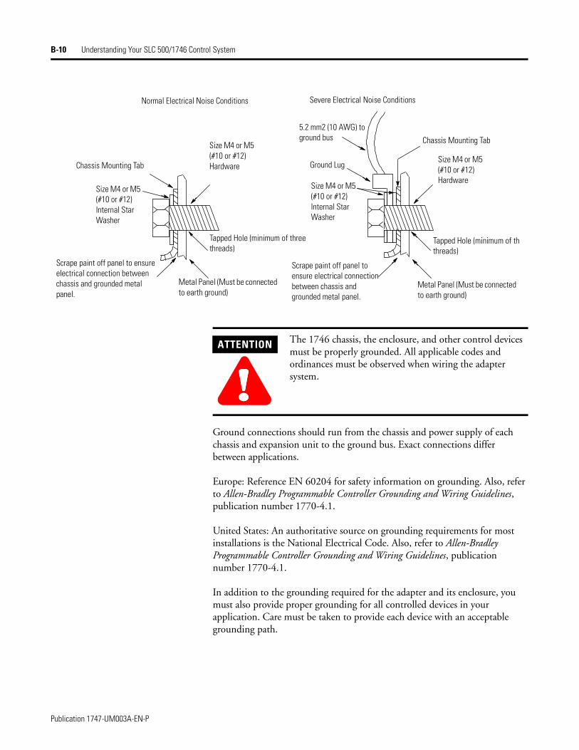
B-10 Understanding Your SLC 500/1746 Control System
Ground connections should run from the chassis and power supply of each chassis and expansion unit to the ground bus. Exact connections differ between applications.
Europe: Reference EN 60204 for safety information on grounding. Also, refer to Allen-Bradley Programmable Controller Grounding and Wiring Guidelines, publication number 1770-4.1.
United States: An authoritative source on grounding requirements for most installations is the National Electrical Code. Also, refer to Allen-Bradley Programmable Controller Grounding and Wiring Guidelines, publication number 1770-4.1.
In addition to the grounding required for the adapter and its enclosure, you must also provide proper grounding for all controlled devices in your application. Care must be taken to provide each device with an acceptable grounding path.
Normal Electrical Noise Conditions
Chassis Mounting Tab
Size M4 or M5 (#10 or #12) Internal Star Washer
Scrape paint off panel to ensure electrical connection between chassis and grounded metal panel.
Metal Panel (Must be connected to earth ground)
Tapped Hole (minimum of three threads)
Size M4 or M5 (#10 or #12) Hardware
Size M4 or M5 (#10 or #12) Hardware
Tapped Hole (minimum of thrthreads)
Metal Panel (Must be connected to earth ground)
Scrape paint off panel to ensure electrical connection between chassis and grounded metal panel.
Size M4 or M5 (#10 or #12) Internal Star Washer
5.2 mm2 (10 AWG) to ground bus Chassis Mounting Tab
Ground Lug
Severe Electrical Noise Conditions
ATTENTION
!!!!The 1746 chassis, the enclosure, and other control devices must be properly grounded. All applicable codes and ordinances must be observed when wiring the adapter system.
Publication 1747-UM003A-EN-P
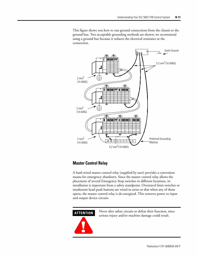
Understanding Your SLC 500/1746 Control System B-11
This figure shows you how to run ground connections from the chassis to the ground bus. Two acceptable grounding methods are shown; we recommend using a ground bus because it reduces the electrical resistance at the connection.
Master Control Relay
A hard-wired master control relay (supplied by user) provides a convenient means for emergency shutdown. Since the master control relay allows the placement of several Emergency-Stop switches in different locations, its installation is important from a safety standpoint. Overtravel limit switches or mushroom head push buttons are wired in series so that when any of them opens, the master control relay is de-energized. This removes power to input and output device circuits.
ATTENTION
!!!!Never alter safety circuits to defeat their function, since serious injury and/or machine damage could result.
2 mm2
(14 AWG)
2 mm2
(14 AWG)
2 mm2
(14 AWG)5.2 mm2 (10 AWG)
Preferred Grounding Method
5.2 mm2 (10 AWG)
Earth Ground
Publication 1747-UM003A-EN-P
B-12 Understanding Your SLC 500/1746 Control System
Place the main power disconnect switch where operators and maintenance personnel have quick and easy access to it. If you mount a disconnect switch inside the system enclosure, place the switch operating handle on the outside of the enclosure, so that you can disconnect power without opening the enclosure.
Whenever any of the emergency-stop switches are opened, power to input and output devices is stopped.
When you use the master control relay to remove power from the external I/O circuits, power continues to be provided to the system’s power supply so that diagnostic indicators on the processor can still be observed.
The master control relay is not a substitute for a disconnect to the controller. It is intended for any situation where the operator must quickly de-energize I/O devices only. When inspecting or installing terminal connections, replacing output fuses, or working on equipment within the enclosure, use the disconnect to shut off power to the rest of the system.
IMPORTANT If you are using a dc power supply, interrupt the dc side rather than the ac side to avoid the additional delay of power supply turn-on and turn-off. The dc power supply should receive its power directly from the fused secondary of the transformer. Connect the power to the dc input and output circuits through a set of master control relay contacts.
IMPORTANT The operator must not control the master control relay with the processor. Provide the operator with the safety of a direct connection between an emergency stop switch and the master control relay.
Publication 1747-UM003A-EN-P
Understanding Your SLC 500/1746 Control System B-13
Emergency-Stop Switches
Adhere to the following points concerning Emergency-Stop switches:
• Do not program Emergency-Stop switches in the program. Any Emergency Stop switch should turn off all machine power by turning off the master control relay.
• Observe all applicable local codes concerning the placement and labeling of Emergency-Stop switches.
• Install Emergency-Stop switches and the master control relay in your system. Make certain that relay contacts have a sufficient rating for your application. Emergency-Stop switches must be easy to reach. See the following schematics.
IMPORTANT The illustrations only show output circuits with Master Control Relay (MCR) protection. In most applications input circuits do not require MCR protection; however, if you need to remove power from all field devices, you must include MCR contacts in series with input power wiring.
Publication 1747-UM003A-EN-P
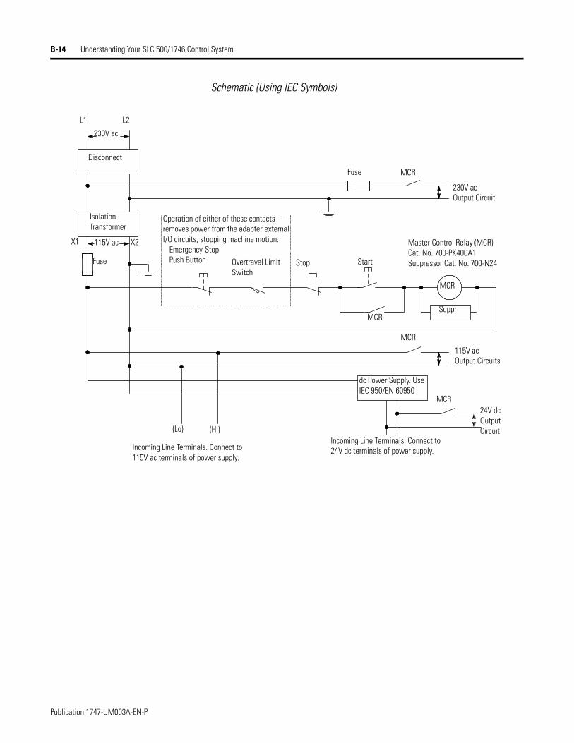
B-14 Understanding Your SLC 500/1746 Control System
Schematic (Using IEC Symbols)
230V ac
L1 L2
Disconnect
Isolation Transformer
115V acX1 X2
Fuse
Fuse
230V acOutput Circuit
115V acOutput Circuits
24V dcOutput Circuit
Operation of either of these contacts removes power from the adapter external I/O circuits, stopping machine motion.
Emergency-Stop Push Button Overtravel Limit
SwitchStop Start
Master Control Relay (MCR) Cat. No. 700-PK400A1Suppressor Cat. No. 700-N24
MCR
Suppr
MCR
(Lo) (Hi)
Incoming Line Terminals. Connect to 115V ac terminals of power supply.
dc Power Supply. Use IEC 950/EN 60950
Incoming Line Terminals. Connect to24V dc terminals of power supply.
MCR
MCR
MCR
Publication 1747-UM003A-EN-P
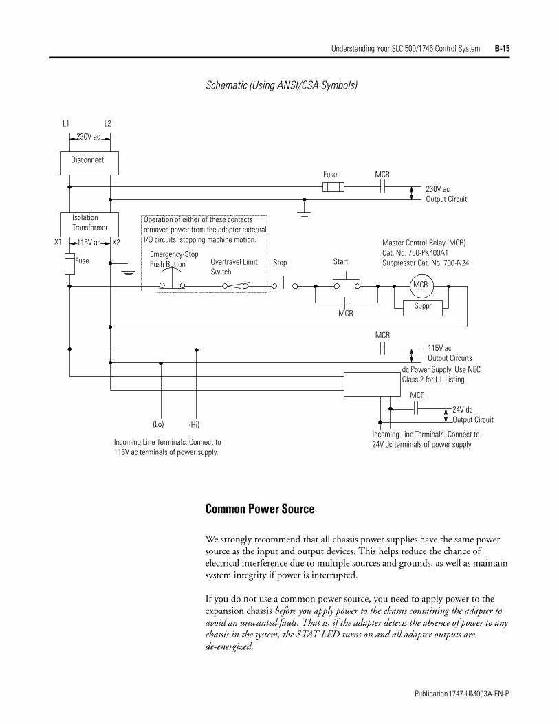
Understanding Your SLC 500/1746 Control System B-15
Schematic (Using ANSI/CSA Symbols)
Common Power Source
We strongly recommend that all chassis power supplies have the same power source as the input and output devices. This helps reduce the chance of electrical interference due to multiple sources and grounds, as well as maintain system integrity if power is interrupted.
If you do not use a common power source, you need to apply power to the expansion chassis before you apply power to the chassis containing the adapter to avoid an unwanted fault. That is, if the adapter detects the absence of power to any chassis in the system, the STAT LED turns on and all adapter outputs are de-energized.
230V ac
L1 L2
Disconnect
Isolation Transformer
115V acX1 X2
Fuse
Fuse
230V acOutput Circuit
115V acOutput Circuits
24V dcOutput Circuit
Operation of either of these contacts removes power from the adapter external I/O circuits, stopping machine motion.
Emergency-Stop Push Button Overtravel Limit
SwitchStop Start
Master Control Relay (MCR) Cat. No. 700-PK400A1Suppressor Cat. No. 700-N24
MCR
Suppr
MCR
(Lo) (Hi)
Incoming Line Terminals. Connect to115V ac terminals of power supply.
dc Power Supply. Use NEC Class 2 for UL Listing
Incoming Line Terminals. Connect to 24V dc terminals of power supply.
MCR
MCR
MCR
Publication 1747-UM003A-EN-P
B-16 Understanding Your SLC 500/1746 Control System
Loss of Power Source
The chassis power supplies are designed to withstand brief power losses without affecting the operation of the system. The time the system is operational during power loss is called “Scan Hold-up time after Loss of Power.” The duration of the power supply hold-up time depends on the number, type and state of the I/O modules, but is typically between 20 ms and 3 s. When the duration of power loss reaches this limit, the power supply signals can no longer provide adequate dc power to the system. This is referred to as a power supply shutdown. The power supply LED is turned off.
In multi-chassis systems, power outages of 20 to 300 ms in duration can cause a power fail error to occur. You can clear this error by cycling power to your system.
Input States on Power Down
The power supply hold-up time as described above is generally longer than the turn-on and turn-off times of the input modules. Because of this, the input state change from “On” to “Off” that occurs when power is removed may be recorded by the 1747-ACN15/-ACNR15 and sent to the processor before the power supply shuts down the system. Understanding this concept is important. The user program should be written to take this effect into account. For example, hard wire power to one spare input. In the user program, check to be sure that one input is On; otherwise, jump to the end of the program and avoid scanning the logic. Use of a common power source as recommended in the previous section is assumed.
Other Types of Line Conditions
Occasionally the power source to the system can be temporarily interrupted. It is also possible that the voltage level drops substantially below the normal line voltage range for a period of time. Both of these conditions are considered to be a loss of power for the system.
Power Conditioning Considerations
There are two types of power conditioning considerations: isolation and suppression.
Publication 1747-UM003A-EN-P
Understanding Your SLC 500/1746 Control System B-17
Isolation
If there is high frequency conducted noise in or around your distribution equipment, we recommend the use of an isolation transformer in the ac line to the power supply. This type of transformer provides isolation from your power distribution system and is often used as a “step down” transformer to reduce line voltage. Any transformer used with the adapter must have a sufficient power rating for its load. This power rating is generally expressed in volt-amperes (VA).
To select an appropriate isolation transformer, you must calculate the power required by the chassis power supply (or supplies if the system has expansion chassis) and any input circuits and output loads that are connected through this transformer.
The power requirement for the input circuits is determined by the number of inputs, the operating voltage, and the nominal input current. The power requirement for output loads is determined by the number of outputs, the load voltage, and load current.
For example, if you have a 1746-P1 power supply, 1746-IV16 16-point dc input module (0.012A at 24V dc) and a 1746-OV16 16-point dc transistor sink output module (0.5A at 24V dc), the power consumed would be:
230 VA + (16)(24V)(0.012A) + (16)(24V)(0.5A) = 426.6 VA
In general, we recommend that the transformer is oversized to provide some margin for line voltage variations and other factors. Typically a transformer that is 25% larger than the calculated VA is sufficient.
Suppression
Most industrial environments are susceptible to power transients or spikes. To help insure fault-free operation and protection of equipment, we recommend suppression devices on power to the equipment in addition to the isolation equipment.
IMPORTANT In this case, 0.5A is the maximum rating of the transistor sink output (at 30° C). If your load draws less than 0.5A, this figure may be reduced accordingly. The output portion of the VA calculation should reflect the current requirements of your loads.
Publication 1747-UM003A-EN-P
B-18 Understanding Your SLC 500/1746 Control System
Special Considerations
The recommendations given previously provide favorable operating conditions for most adapter installations. Your application may involve one or more of the following adverse conditions. Additional measures can be taken to minimize the effect of these conditions.
Excessive Line Voltage Variations
The best solution for excessive line voltage variation is to correct any feeder problems in your distribution system. Where this does not solve the line variation problem, or in certain critical applications, use a constant voltage transformer. If you require a constant voltage transformer, connect it to the power supply and all input devices connected to the 1747-ACN15/-ACNR15 chassis.
Connect output devices on the same power line, but their connection along the power line is normally made before the constant voltage transformer. A constant voltage transformer must have a sufficient power rating for its load.
Excessive Noise
When you operate the 1747-ACN15/-ACNR15 module in a “noise polluted” industrial environment, special consideration should be given to possible electrical interference.
The following reduces the effect of electrical interference:
• 1747-ACN15/-ACNR15 design features
• proper mounting of adapter within an enclosure
• proper equipment grounding
• proper routing of wiring
• proper suppression added to noise generating devices
Inductive loads, such as relays, solenoids, and motor starters, when operated by “hard contacts” like push buttons or selector switches, generate surges on the ac line. Suppression may be necessary when such loads are connected as output devices or when connected to the same supply line that powers the adapter.
Lack of surge suppression on inductive loads may contribute to faults and sporadic operation, RAM can be corrupted (lost), and I/O modules may appear to be faulty or reset themselves.
Publication 1747-UM003A-EN-P
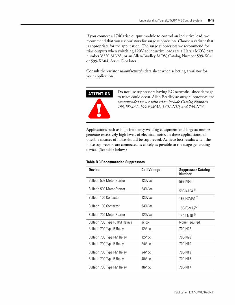
Understanding Your SLC 500/1746 Control System B-19
If you connect a 1746 triac output module to control an inductive load, we recommend that you use varistors for surge suppression. Choose a varistor that is appropriate for the application. The surge suppressors we recommend for triac outputs when switching 120V ac inductive loads are a Harris MOV, part number V220 MA2A, or an Allen-Bradley MOV, Catalog Number 599-K04 or 599-KA04, Series C or later.
Consult the varistor manufacturer’s data sheet when selecting a varistor for your application.
Applications such as high-frequency welding equipment and large ac motors generate excessively high levels of electrical noise. In these applications, all possible sources of noise should be suppressed. Achieve best results when the noise suppressors are connected as closely as possible to the surge generating device. (See table below.)
ATTENTION
!!!!Do not use suppressors having RC networks, since damage to triacs could occur. Allen-Bradley ac surge suppressors not recommended for use with triacs include Catalog Numbers 199-FSMA1, 199-FSMA2, 1401-N10, and 700-N24.
Table B.3 Recommended Suppressors
Device Coil Voltage Suppressor Catalog Number
Bulletin 509 Motor Starter
Bulletin 509 Motor Starter
120V ac
240V ac
599-K04(1)
599-KA04(1)
Bulletin 100 Contactor
Bulletin 100 Contactor
120V ac
240V ac
199-FSMA1(2)
199-F5MA2(2)
Bulletin 709 Motor Starter 120V ac 1401-N10(2)
Bulletin 700 Type R, RM Relays ac coil None Required
Bulletin 700 Type R Relay
Bulletin 700 Type RM Relay
12V dc
12V dc
700-N22
700-N28
Bulletin 700 Type R Relay
Bulletin 700 Type RM Relay
24V dc
24V dc
700-N10
700-N13
Bulletin 700 Type R Relay
Bulletin 700 Type RM Relay
48V dc
48V dc
700-N16
700-N17
Publication 1747-UM003A-EN-P
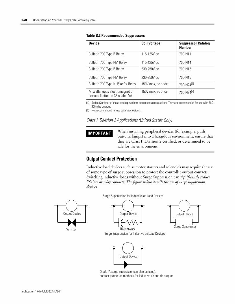
B-20 Understanding Your SLC 500/1746 Control System
Class I, Division 2 Applications (United States Only)
Output Contact ProtectionInductive load devices such as motor starters and solenoids may require the use of some type of surge suppression to protect the controller output contacts. Switching inductive loads without Surge Suppression can significantly reduce lifetime or relay contacts. The figure below details the use of surge suppression devices.
Bulletin 700 Type R Relay
Bulletin 700 Type RM Relay
115-125V dc
115-125V dc
700-N11
700-N14
Bulletin 700 Type R Relay
Bulletin 700 Type RM Relay
230-250V dc
230-250V dc
700-N12
700-N15
Bulletin 700 Type N, P, or PK Relay 150V max, ac or dc 700-N24(2)
Miscellaneous electromagnetic devices limited to 35 sealed VA
150V max, ac or dc 700-N24(2)
(1) Series C or later of these catalog numbers do not contain capacitors. They are recommended for use with SLC 500 triac outputs.
(2) Not recommended for use with triac outputs.
IMPORTANT When installing peripheral devices (for example, push buttons, lamps) into a hazardous environment, ensure that they are Class I, Division 2 certified, or determined to be safe for the environment.
Table B.3 Recommended Suppressors
Device Coil Voltage Suppressor Catalog Number
- +
Surge Suppression for Inductive ac Load Devices
Output Device Output Device Output Device
Output Device
Surge Suppression for Inductive dc Load Devices
Diode (A surge suppressor can also be used).contact protection methods for inductive ac and dc outputs
Varistor RC NetworkSurge Suppressor
Publication 1747-UM003A-EN-P
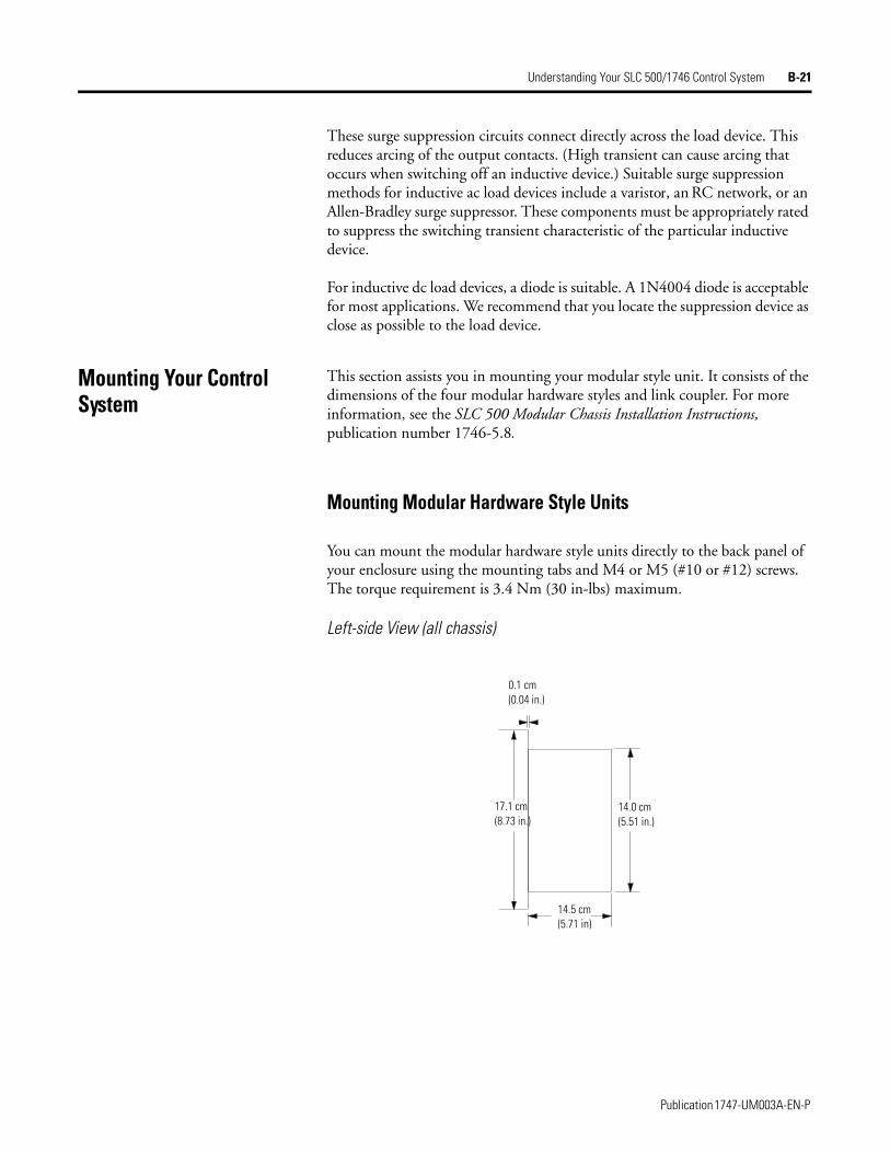
Understanding Your SLC 500/1746 Control System B-21
These surge suppression circuits connect directly across the load device. This reduces arcing of the output contacts. (High transient can cause arcing that occurs when switching off an inductive device.) Suitable surge suppression methods for inductive ac load devices include a varistor, an RC network, or an Allen-Bradley surge suppressor. These components must be appropriately rated to suppress the switching transient characteristic of the particular inductive device.
For inductive dc load devices, a diode is suitable. A 1N4004 diode is acceptable for most applications. We recommend that you locate the suppression device as close as possible to the load device.
Mounting Your Control System
This section assists you in mounting your modular style unit. It consists of the dimensions of the four modular hardware styles and link coupler. For more information, see the SLC 500 Modular Chassis Installation Instructions, publication number 1746-5.8.
Mounting Modular Hardware Style Units
You can mount the modular hardware style units directly to the back panel of your enclosure using the mounting tabs and M4 or M5 (#10 or #12) screws. The torque requirement is 3.4 Nm (30 in-lbs) maximum.
Left-side View (all chassis)
0.1 cm(0.04 in.)
14.0 cm (5.51 in.)
14.5 cm (5.71 in)
17.1 cm (8.73 in.)
Publication 1747-UM003A-EN-P
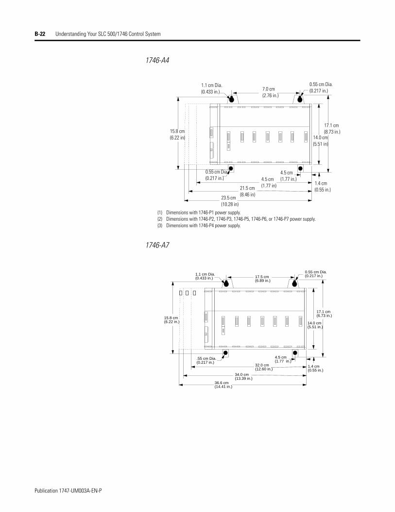
B-22 Understanding Your SLC 500/1746 Control System
1746-A4
1746-A7
(1) Dimensions with 1746-P1 power supply.(2) Dimensions with 1746-P2, 1746-P3, 1746-P5, 1746-P6, or 1746-P7 power supply.(3) Dimensions with 1746-P4 power supply.
1.1 cm Dia. (0.433 in.) 7.0 cm
(2.76 in.)
0.55 cm Dia. (0.217 in.)
17.1 cm (8.73 in.)
14.0 cm (5.51 in)
1.4 cm (0.55 in.)
4.5 cm(1.77 in.)
0.55 cm Dia. (0.217 in.) 4.5 cm
(1.77 in)21.5 cm (8.46 in)
23.5 cm (10.28 in)
15.8 cm (6.22 in)
➊➋➌
17.5 cm(6.89 in.)
17.1 cm(6.73 in.)
15.8 cm(6.22 in.)
.55 cm Dia.(0.217 in.)
32.0 cm(12.60 in.)
34.0 cm(13.39 in.)
1.4 cm(0.55 in.)
4.5 cm(1.77 in.)
14.0 cm(5.51 in.)
0.55 cm Dia.(0.217 in.)1.1 cm Dia.
(0.433 in.)
36.6 cm(14.41 in.)
Publication 1747-UM003A-EN-P
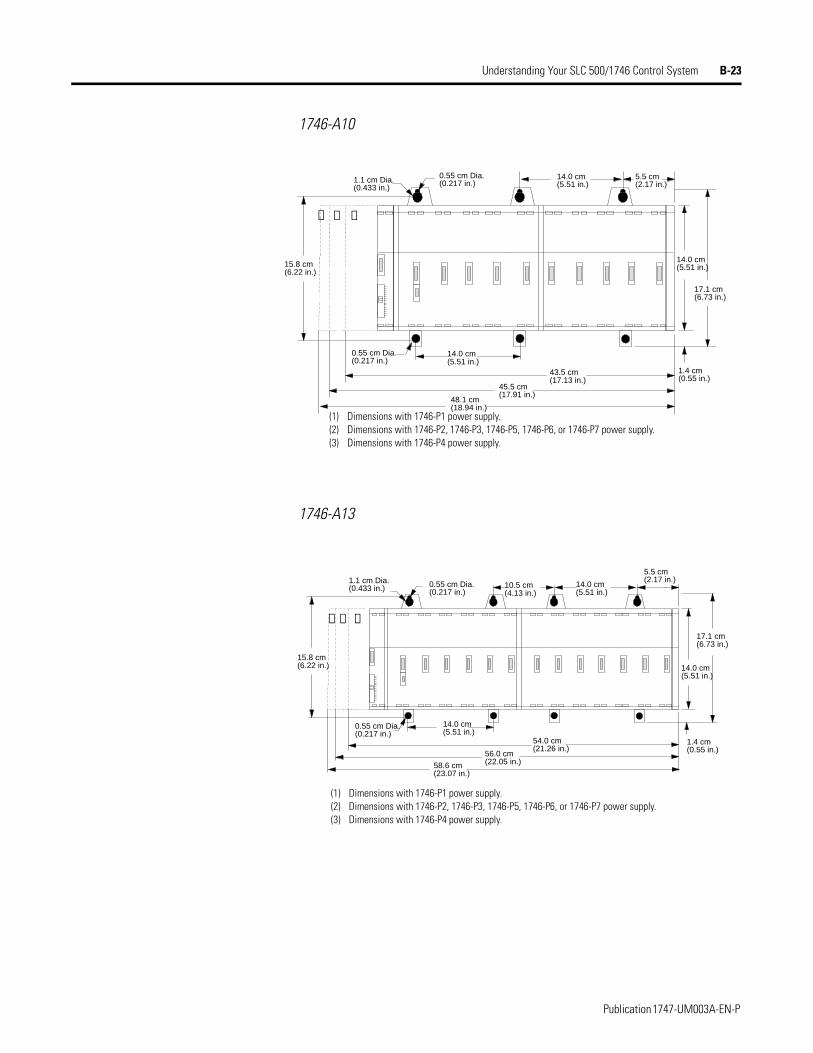
Understanding Your SLC 500/1746 Control System B-23
1746-A10
1746-A13
➊➋➌
5.5 cm(2.17 in.)
0.55 cm Dia.(0.217 in.)1.1 cm Dia.
(0.433 in.)
14.0 cm(5.51 in.)
43.5 cm(17.13 in.)
45.5 cm(17.91 in.)
0.55 cm Dia.(0.217 in.)
15.8 cm(6.22 in.)
17.1 cm(6.73 in.)
14.0 cm(5.51 in.)
14.0 cm(5.51 in.)
1.4 cm(0.55 in.)
48.1 cm(18.94 in.)
(1) Dimensions with 1746-P1 power supply.(2) Dimensions with 1746-P2, 1746-P3, 1746-P5, 1746-P6, or 1746-P7 power supply.(3) Dimensions with 1746-P4 power supply.
➊➋➌
0.55 cm Dia.(0.217 in.)
5.5 cm(2.17 in.)1.1 cm Dia.
(0.433 in.) 0.55 cm Dia.(0.217 in.)
10.5 cm(4.13 in.)
14.0 cm(5.51 in.)
54.0 cm(21.26 in.)
56.0 cm(22.05 in.)
15.8 cm(6.22 in.) 14.0 cm
(5.51 in.)
1.4 cm(0.55 in.)
14.0 cm(5.51 in.)
17.1 cm(6.73 in.)
58.6 cm(23.07 in.)
(1) Dimensions with 1746-P1 power supply.(2) Dimensions with 1746-P2, 1746-P3, 1746-P5, 1746-P6, or 1746-P7 power supply.(3) Dimensions with 1746-P4 power supply.
Publication 1747-UM003A-EN-P
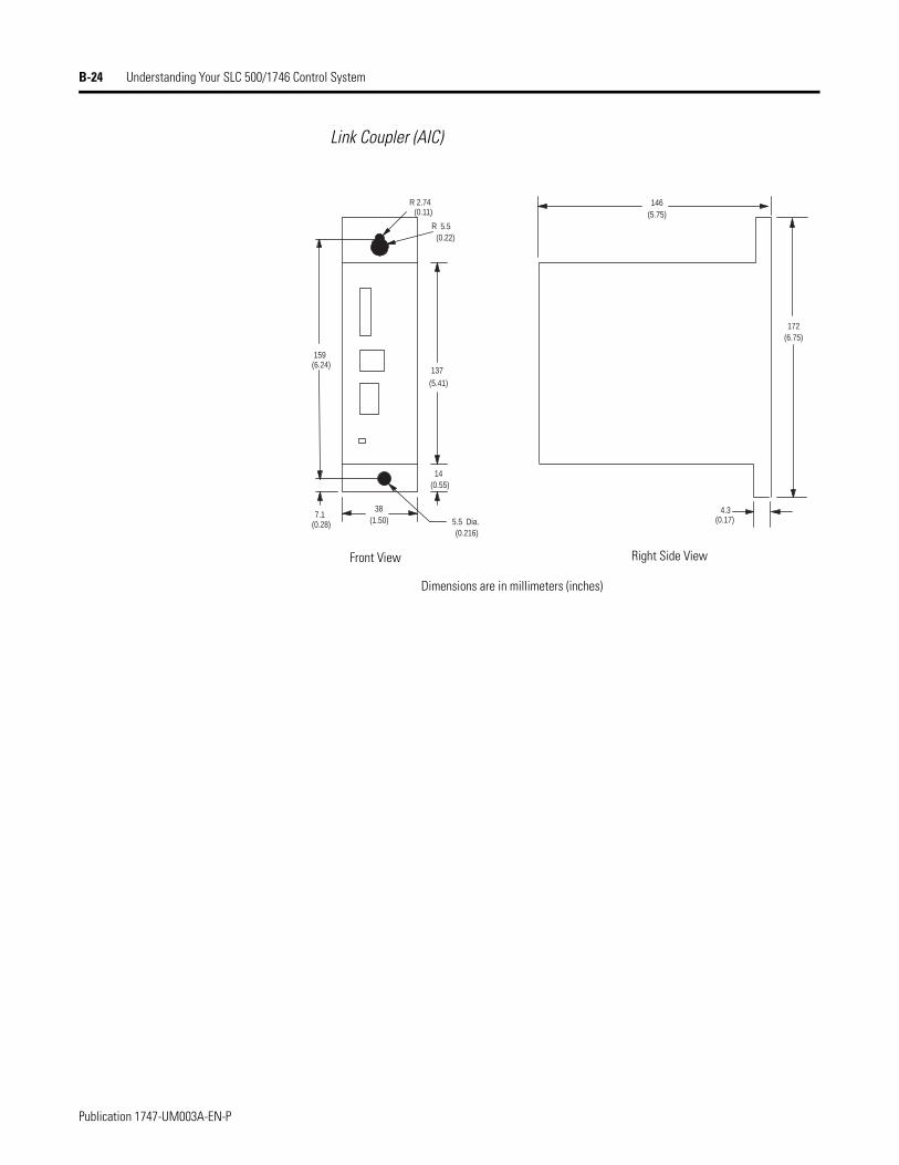
B-24 Understanding Your SLC 500/1746 Control System
Link Coupler (AIC)
159(6.24)
137
(5.41)
14(0.55)
38(1.50)
R 2.74(0.11)
5.5 Dia.(0.216)
5.5(0.22)
146(5.75)
4.3(0.17)
R
172(6.75)
7.1(0.28)
Front View
Dimensions are in millimeters (inches)
Right Side View
Publication 1747-UM003A-EN-P
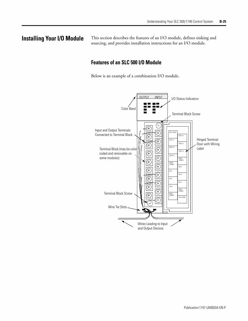
Understanding Your SLC 500/1746 Control System B-25
Installing Your I/O Module This section describes the features of an I/O module, defines sinking and sourcing, and provides installation instructions for an I/O module.
Features of an SLC 500 I/O Module
Below is an example of a combination I/O module.
OUT 1
OUT 3
OUT 0
OUT 2
OUTPUT INPUT
OUT 5
NOTUSED
IN 5
OUT 4
IN 0
AC COM
NOTUSED
NOTUSED
NOTUSED
IN 4
IN 3
IN 2
IN 1
VAC-VDC
Color Band
Input and Output Terminals Connected to Terminal Block
Terminal Block (may be color coded and removable on some modules)
Terminal Block Screw
Wire Tie Slots
I/O Status Indicators
Terminal Block Screw
Hinged Terminal Door with Wiring Label
Wires Leading to Input and Output Devices
Publication 1747-UM003A-EN-P
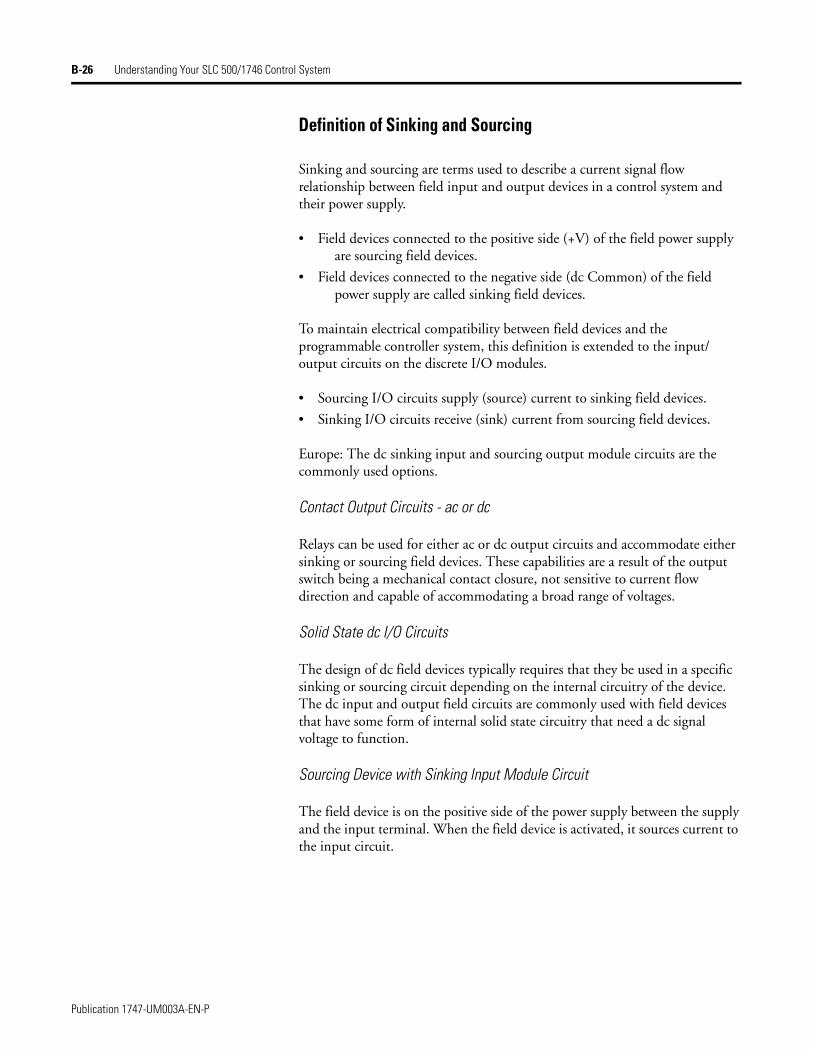
B-26 Understanding Your SLC 500/1746 Control System
Definition of Sinking and Sourcing
Sinking and sourcing are terms used to describe a current signal flow relationship between field input and output devices in a control system and their power supply.
• Field devices connected to the positive side (+V) of the field power supply are sourcing field devices.
• Field devices connected to the negative side (dc Common) of the field power supply are called sinking field devices.
To maintain electrical compatibility between field devices and the programmable controller system, this definition is extended to the input/output circuits on the discrete I/O modules.
• Sourcing I/O circuits supply (source) current to sinking field devices.
• Sinking I/O circuits receive (sink) current from sourcing field devices.
Europe: The dc sinking input and sourcing output module circuits are the commonly used options.
Contact Output Circuits - ac or dc
Relays can be used for either ac or dc output circuits and accommodate either sinking or sourcing field devices. These capabilities are a result of the output switch being a mechanical contact closure, not sensitive to current flow direction and capable of accommodating a broad range of voltages.
Solid State dc I/O Circuits
The design of dc field devices typically requires that they be used in a specific sinking or sourcing circuit depending on the internal circuitry of the device. The dc input and output field circuits are commonly used with field devices that have some form of internal solid state circuitry that need a dc signal voltage to function.
Sourcing Device with Sinking Input Module Circuit
The field device is on the positive side of the power supply between the supply and the input terminal. When the field device is activated, it sources current to the input circuit.
Publication 1747-UM003A-EN-P
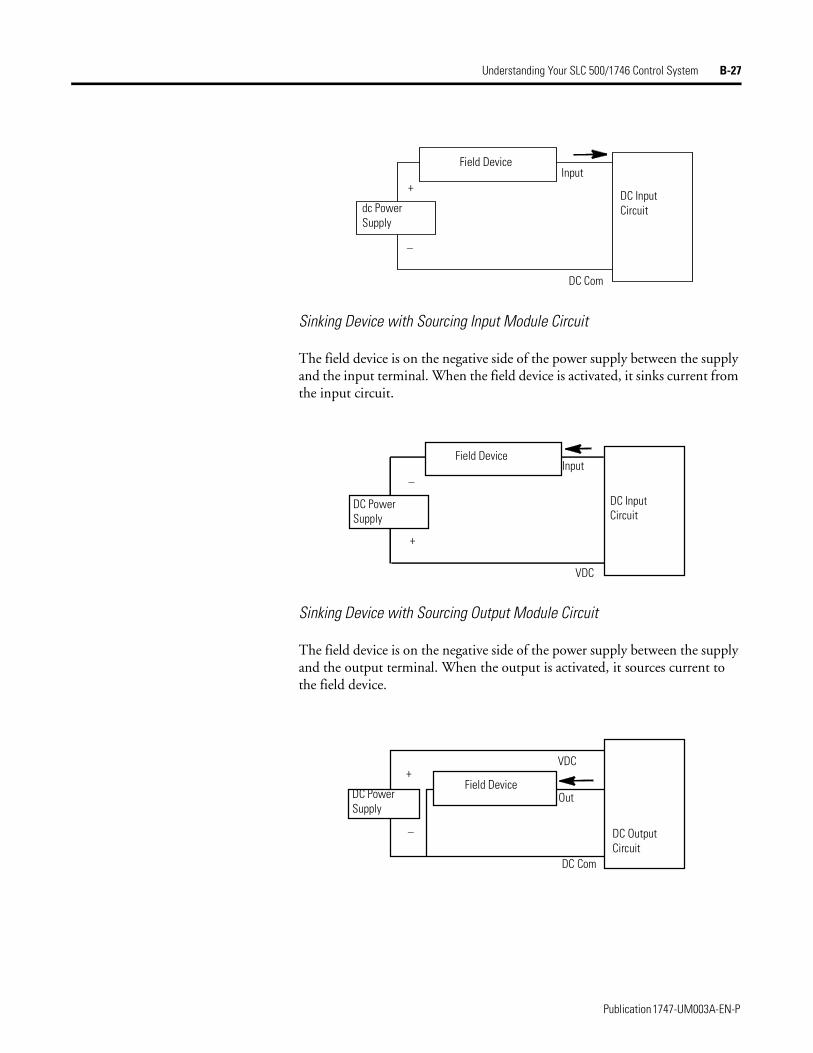
Understanding Your SLC 500/1746 Control System B-27
Sinking Device with Sourcing Input Module Circuit
The field device is on the negative side of the power supply between the supply and the input terminal. When the field device is activated, it sinks current from the input circuit.
Sinking Device with Sourcing Output Module Circuit
The field device is on the negative side of the power supply between the supply and the output terminal. When the output is activated, it sources current to the field device.
DC Input Circuit
DC Com
Field Device
dc Power Supply
+
–
Input
DC Input Circuit
VDC
Field Device
DC Power Supply
+
–Input
DC Output Circuit
VDC
Out
DC Com
Field DeviceDC Power Supply
+
–
Publication 1747-UM003A-EN-P
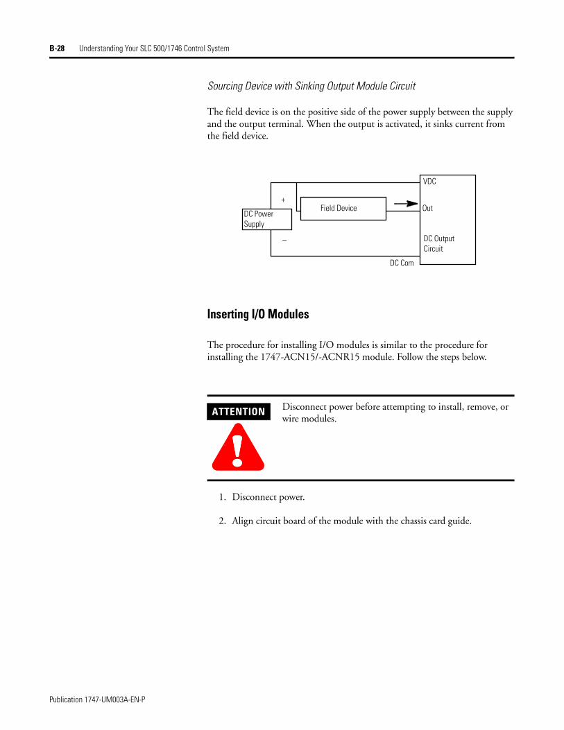
B-28 Understanding Your SLC 500/1746 Control System
Sourcing Device with Sinking Output Module Circuit
The field device is on the positive side of the power supply between the supply and the output terminal. When the output is activated, it sinks current from the field device.
Inserting I/O Modules
The procedure for installing I/O modules is similar to the procedure for installing the 1747-ACN15/-ACNR15 module. Follow the steps below.
1. Disconnect power.
2. Align circuit board of the module with the chassis card guide.
ATTENTION
!!!!Disconnect power before attempting to install, remove, or wire modules.
DC Power Supply
Field Device
VDC
Out
DC Output Circuit
DC Com
+
–
Publication 1747-UM003A-EN-P

Understanding Your SLC 500/1746 Control System B-29
3. Slide the module into the chassis until the top and bottom tabs lock into place.
4. Insert the wire tie in the slots.
5. Route the wires down and away from the module, securing them with the wire tie.
Publication 1747-UM003A-EN-P
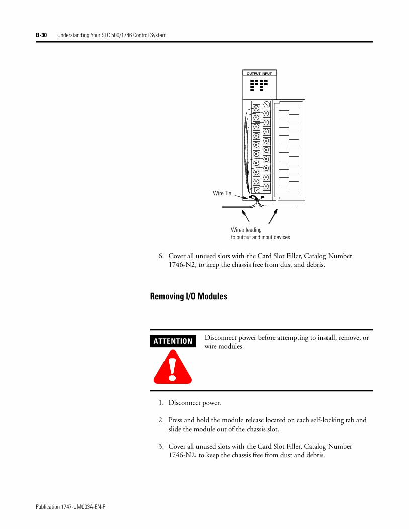
B-30 Understanding Your SLC 500/1746 Control System
6. Cover all unused slots with the Card Slot Filler, Catalog Number 1746-N2, to keep the chassis free from dust and debris.
Removing I/O Modules
1. Disconnect power.
2. Press and hold the module release located on each self-locking tab and slide the module out of the chassis slot.
3. Cover all unused slots with the Card Slot Filler, Catalog Number 1746-N2, to keep the chassis free from dust and debris.
ATTENTION
!!!!Disconnect power before attempting to install, remove, or wire modules.
OUTPUT INPUT
Wires leading to output and input devices
Wire Tie
Publication 1747-UM003A-EN-P
Understanding Your SLC 500/1746 Control System B-31
Wiring the I/O Modules The following are general recommendations for wiring I/O devices.
Use acceptable wire gauge - The I/O wiring terminals are designed to accept two wires per terminal (maximum) of the following size wire:
• Europe: 2mm2 cross section or smaller
• United States: 14 AWG or smaller stranded wires
Label wires - Label wiring to I/O devices, power sources, and ground. Use tape, shrink-tubing, or other dependable means for labeling purposes. In addition to labeling, use colored insulation to identify wiring based on signal characteristics. For example, you may use blue for dc I/O wiring and red for ac I/O wiring.
Secure wires - Route the wires down and away from the module, securing them with the cable tie.
Bundle wires - Bundle wiring for each similar I/O device together. If you use ducts, allow at least 5 cm (2 in.) between the ducts and the controller so there is sufficient room to wire the devices.
Identify terminals - Terminal cover plates have a write-on area for each terminal. Use this area to identify your I/O devices. Label the removable terminal block if you have not already.
ATTENTION
!!!!Before you install and wire I/O devices, disconnect power from the controller and any other source to the I/O devices.
ATTENTION
!!!!Calculate the maximum possible current in each power and common wire. Observe all local electrical codes dictating the maximum current allowable for each wire size. Current above the maximum ratings may cause wiring to overheat, which can cause damage.Capacitors on input modules have a stored charge that can cause a non-lethal shock. Avoid mounting the controller in a position where installation or service personnel would be in danger from startle reaction.
Publication 1747-UM003A-EN-P
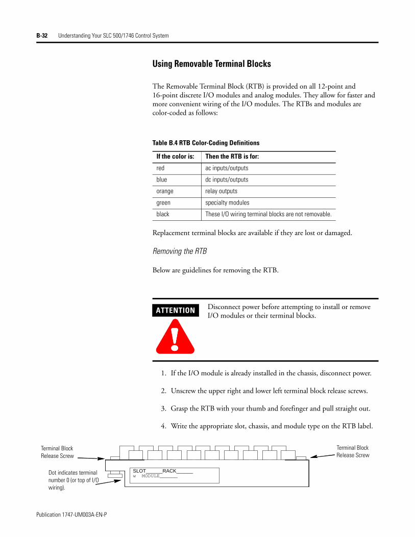
B-32 Understanding Your SLC 500/1746 Control System
Using Removable Terminal Blocks
The Removable Terminal Block (RTB) is provided on all 12-point and 16-point discrete I/O modules and analog modules. They allow for faster and more convenient wiring of the I/O modules. The RTBs and modules are color-coded as follows:
Replacement terminal blocks are available if they are lost or damaged.
Removing the RTB
Below are guidelines for removing the RTB.
1. If the I/O module is already installed in the chassis, disconnect power.
2. Unscrew the upper right and lower left terminal block release screws.
3. Grasp the RTB with your thumb and forefinger and pull straight out.
4. Write the appropriate slot, chassis, and module type on the RTB label.
Table B.4 RTB Color-Coding Definitions
If the color is: Then the RTB is for:
red ac inputs/outputs
blue dc inputs/outputs
orange relay outputs
green specialty modules
black These I/O wiring terminal blocks are not removable.
ATTENTION
!!!!Disconnect power before attempting to install or remove I/O modules or their terminal blocks.
SLOT______RACK______w MODULE______
Terminal Block Release Screw
Terminal Block Release Screw
Dot indicates terminal number 0 (or top of I/O wiring).
Publication 1747-UM003A-EN-P
Understanding Your SLC 500/1746 Control System B-33
Installing the RTB
Below are guidelines for installing the RTB.
1. Be sure the color of the RTB matches the color band on the module.
2. Write the appropriate slot, chassis, and module type on the RTB label.
3. Disconnect power.
4. Align the terminal block release screws with the mating connector in the module.
5. Press the RTB firmly onto the connector contacts.
6. Tighten the terminal block release screws. To avoid cracking the terminal block, alternate the tightening of the screws.
ATTENTION
!!!!Inserting a wired RTB on an incorrect module can damage the module circuitry when power is applied.
ATTENTION
!!!!Disconnect power before attempting to install or remove I/O modules or their terminal blocks.
Publication 1747-UM003A-EN-P
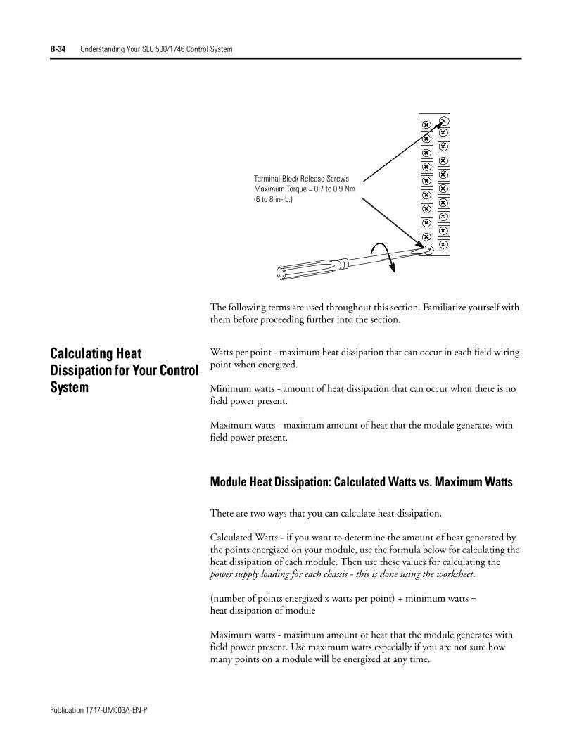
B-34 Understanding Your SLC 500/1746 Control System
The following terms are used throughout this section. Familiarize yourself with them before proceeding further into the section.
Calculating Heat Dissipation for Your Control System
Watts per point - maximum heat dissipation that can occur in each field wiring point when energized.
Minimum watts - amount of heat dissipation that can occur when there is no field power present.
Maximum watts - maximum amount of heat that the module generates with field power present.
Module Heat Dissipation: Calculated Watts vs. Maximum Watts
There are two ways that you can calculate heat dissipation.
Calculated Watts - if you want to determine the amount of heat generated by the points energized on your module, use the formula below for calculating the heat dissipation of each module. Then use these values for calculating the power supply loading for each chassis - this is done using the worksheet.
(number of points energized x watts per point) + minimum watts = heat dissipation of module
Maximum watts - maximum amount of heat that the module generates with field power present. Use maximum watts especially if you are not sure how many points on a module will be energized at any time.
Terminal Block Release ScrewsMaximum Torque = 0.7 to 0.9 Nm(6 to 8 in-lb.)
Publication 1747-UM003A-EN-P
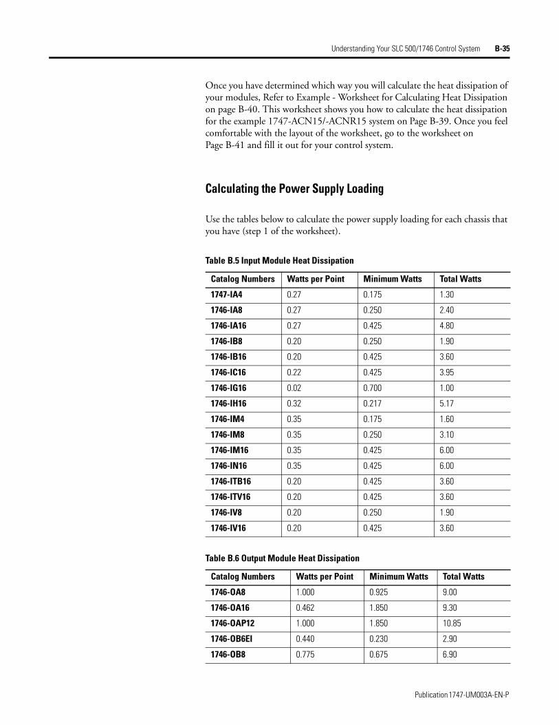
Understanding Your SLC 500/1746 Control System B-35
Once you have determined which way you will calculate the heat dissipation of your modules, Refer to Example - Worksheet for Calculating Heat Dissipation on page B-40. This worksheet shows you how to calculate the heat dissipation for the example 1747-ACN15/-ACNR15 system on Page B-39. Once you feel comfortable with the layout of the worksheet, go to the worksheet on Page B-41 and fill it out for your control system.
Calculating the Power Supply Loading
Use the tables below to calculate the power supply loading for each chassis that you have (step 1 of the worksheet).
Table B.5 Input Module Heat Dissipation
Catalog Numbers Watts per Point Minimum Watts Total Watts
1747-IA4 0.27 0.175 1.30
1746-IA8 0.27 0.250 2.40
1746-IA16 0.27 0.425 4.80
1746-IB8 0.20 0.250 1.90
1746-IB16 0.20 0.425 3.60
1746-IC16 0.22 0.425 3.95
1746-IG16 0.02 0.700 1.00
1746-IH16 0.32 0.217 5.17
1746-IM4 0.35 0.175 1.60
1746-IM8 0.35 0.250 3.10
1746-IM16 0.35 0.425 6.00
1746-IN16 0.35 0.425 6.00
1746-ITB16 0.20 0.425 3.60
1746-ITV16 0.20 0.425 3.60
1746-IV8 0.20 0.250 1.90
1746-IV16 0.20 0.425 3.60
Table B.6 Output Module Heat Dissipation
Catalog Numbers Watts per Point Minimum Watts Total Watts
1746-OA8 1.000 0.925 9.00
1746-OA16 0.462 1.850 9.30
1746-OAP12 1.000 1.850 10.85
1746-OB6EI 0.440 0.230 2.90
1746-OB8 0.775 0.675 6.90
Publication 1747-UM003A-EN-P
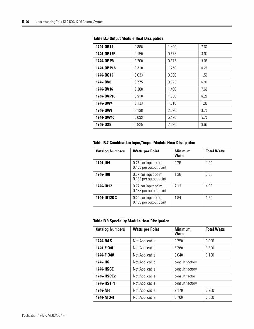
B-36 Understanding Your SLC 500/1746 Control System
1746-OB16 0.388 1.400 7.60
1746-OB16E 0.150 0.675 3.07
1746-OBP8 0.300 0.675 3.08
1746-OBP16 0.310 1.250 6.26
1746-OG16 0.033 0.900 1.50
1746-OV8 0.775 0.675 6.90
1746-OV16 0.388 1.400 7.60
1746-OVP16 0.310 1.250 6.26
1746-OW4 0.133 1.310 1.90
1746-OW8 0.138 2.590 3.70
1746-OW16 0.033 5.170 5.70
1746-OX8 0.825 2.590 8.60
Table B.7 Combination Input/Output Module Heat Dissipation
Catalog Numbers Watts per Point Minimum Watts
Total Watts
1746-IO4 0.27 per input point0.133 per output point
0.75 1.60
1746-IO8 0.27 per input point0.133 per output point
1.38 3.00
1746-IO12 0.27 per input point0.133 per output point
2.13 4.60
1746-IO12DC 0.20 per input point0.133 per output point
1.84 3.90
Table B.8 Speciality Module Heat Dissipation
Catalog Numbers Watts per Point Minimum Watts
Total Watts
1746-BAS Not Applicable 3.750 3.800
1746-FIO4I Not Applicable 3.760 3.800
1746-FIO4V Not Applicable 3.040 3.100
1746-HS Not Applicable consult factory
1746-HSCE Not Applicable consult factory
1746-HSCE2 Not Applicable consult factor
1746-HSTP1 Not Applicable consult factory
1746-NI4 Not Applicable 2.170 2.200
1746-NIO4I Not Applicable 3.760 3.800
Table B.6 Output Module Heat Dissipation
Publication 1747-UM003A-EN-P
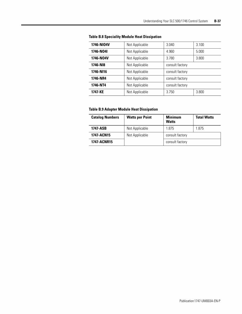
Understanding Your SLC 500/1746 Control System B-37
1746-NIO4V Not Applicable 3.040 3.100
1746-NO4I Not Applicable 4.960 5.000
1746-NO4V Not Applicable 3.780 3.800
1746-NI8 Not Applicable consult factory
1746-NI16 Not Applicable consult factory
1746-NR4 Not Applicable consult factory
1746-NT4 Not Applicable consult factory
1747-KE Not Applicable 3.750 3.800
Table B.9 Adapter Module Heat Dissipation
Catalog Numbers Watts per Point Minimum Watts
Total Watts
1747-ASB Not Applicable 1.875 1.875
1747-ACN15 Not Applicable consult factory
1747-ACNR15 consult factory
Table B.8 Speciality Module Heat Dissipation
Publication 1747-UM003A-EN-P
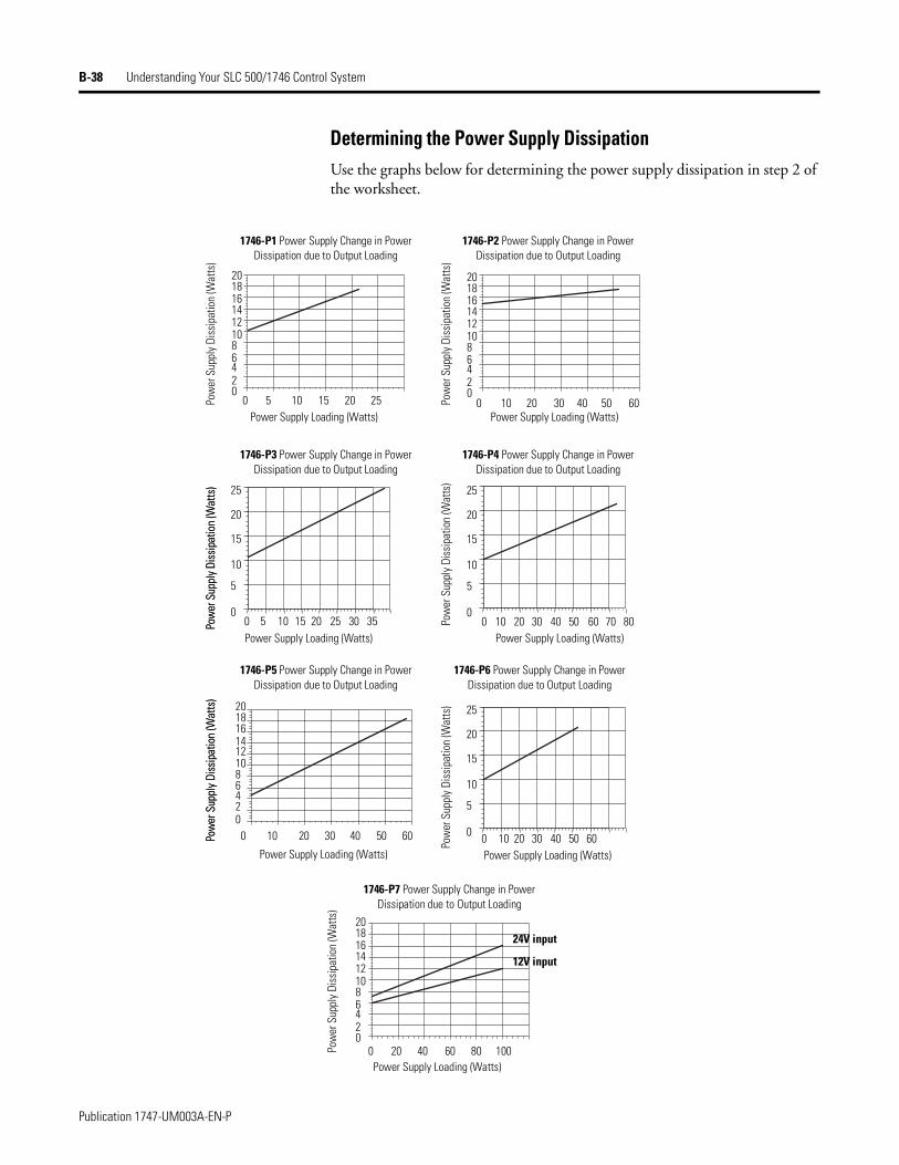
B-38 Understanding Your SLC 500/1746 Control System
Determining the Power Supply DissipationUse the graphs below for determining the power supply dissipation in step 2 of the worksheet.
1746-P2 Power Supply Change in Power Dissipation due to Output Loading
1746-P1 Power Supply Change in Power Dissipation due to Output Loading
1746-P3 Power Supply Change in Power Dissipation due to Output Loading
1746-P4 Power Supply Change in Power Dissipation due to Output Loading
Power Supply Loading (Watts)
Power Supply Loading (Watts) Power Supply Loading (Watts)
Power Supply Loading (Watts)
1746-P5 Power Supply Change in Power Dissipation due to Output Loading
Pow
er S
uppl
y Dis
sipa
tion
(Wat
ts)
Pow
er S
uppl
y Di
ssip
atio
n (W
atts
)
Pow
er S
uppl
y Dis
sipa
tion
(Wat
ts)
Pow
er S
uppl
y Dis
sipa
tion
(Wat
ts)
Pow
er S
uppl
y Dis
sipa
tion
(Wat
ts)
Pow
er S
uppl
y Di
ssip
atio
n (W
atts
)
Power Supply Loading (Watts) Power Supply Loading (Watts)
1746-P6 Power Supply Change in Power Dissipation due to Output Loading
1746-P7 Power Supply Change in Power Dissipation due to Output Loading
Power Supply Loading (Watts)
201816
0
1412108642
0 5 10 15 20 25
30
0 10 20 30 40 50 60
0 5 10 15 20 25 35
0 10 20 30 40 50 60
0 10 20 30 40 50 60
0 10 20 30 40 50 60
0 20 40 60 80 100
70 80
201816
0
1412108642
201816
0
1412108642
201816
0
1412108642
25
20
15
10
5
0
25
20
15
10
5
0
25
20
15
10
5
0Pow
er S
uppl
y Di
ssip
atio
n (W
atts
)
Pow
er S
uppl
y Di
ssip
atio
n (W
atts
)Po
wer
Sup
ply
Diss
ipat
ion
(Wat
ts)
24V input
12V input
Publication 1747-UM003A-EN-P
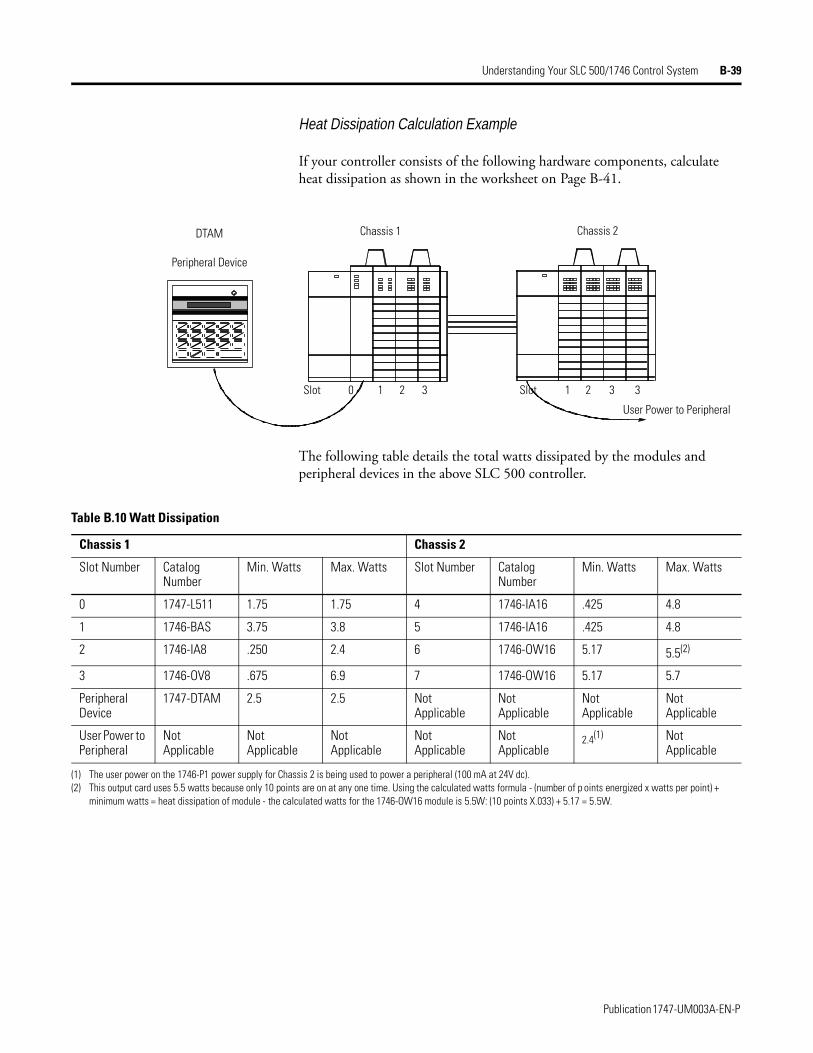
Understanding Your SLC 500/1746 Control System B-39
Heat Dissipation Calculation Example
If your controller consists of the following hardware components, calculate heat dissipation as shown in the worksheet on Page B-41.
The following table details the total watts dissipated by the modules and peripheral devices in the above SLC 500 controller.
DTAM Chassis 1 Chassis 2
Peripheral Device
Slot 0 1 2 3 Slot 1 2 3 3
User Power to Peripheral
Table B.10 Watt Dissipation
Chassis 1 Chassis 2
Slot Number Catalog Number
Min. Watts Max. Watts Slot Number Catalog Number
Min. Watts Max. Watts
0 1747-L511 1.75 1.75 4 1746-IA16 .425 4.8
1 1746-BAS 3.75 3.8 5 1746-IA16 .425 4.8
2 1746-IA8 .250 2.4 6 1746-OW16 5.17 5.5(2)
3 1746-OV8 .675 6.9 7 1746-OW16 5.17 5.7
Peripheral Device
1747-DTAM 2.5 2.5 Not Applicable
Not Applicable
Not Applicable
Not Applicable
User Power to Peripheral
Not Applicable
Not Applicable
Not Applicable
Not Applicable
Not Applicable
2.4(1) Not Applicable
(1) The user power on the 1746-P1 power supply for Chassis 2 is being used to power a peripheral (100 mA at 24V dc).(2) This output card uses 5.5 watts because only 10 points are on at any one time. Using the calculated watts formula - (number of p oints energized x watts per point) +
minimum watts = heat dissipation of module - the calculated watts for the 1746-OW16 module is 5.5W: (10 points X.033) + 5.17 = 5.5W.
Publication 1747-UM003A-EN-P
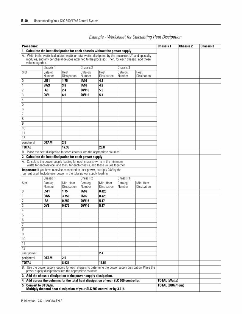
B-40 Understanding Your SLC 500/1746 Control System
Example - Worksheet for Calculating Heat Dissipation
Procedure: Chassis 1 Chassis 2 Chassis 31. Calculate the heat dissipation for each chassis without the power supplyA. Write in the watts (calculated watts or total watts) dissipated by the processor, I/O and specialty
modules, and any peripheral devices attached to the processor. Then, for each chassis, add these values together.
Chassis 1 Chassis 2 Chassis 3Slot Catalog
NumberHeat Dissipation
Catalog Number
Heat Dissipation
Catalog Number
Heat Dissipation
0 L511 1.75 IA16 4.81 BAS 3.8 IA16 4.82 IA8 2.4 OW16 5.53 OV8 6.9 OW16 5.7456789101112peripheral DTAM 2.5TOTAL 17.35 20.8B. Place the heat dissipation for each chassis into the appropriate columns.2. Calculate the heat dissipation for each power supplyA. Calculate the power supply loading for each chassis (write in the minimum
watts for each device, and then, for each chassis, add these values together.Important: If you have a device connected to user power, multiply 24V by the current used. Include user power in the total power supply loading
Chassis 1 Chassis 2 Chassis 3Slot Catalog
NumberMin. Heat Dissipation
Catalog Number
Min. Heat Dissipation
Catalog Number
Min. Heat Dissipation
0 L511 1.75 IA16 0.4251 BAS 3.750 IA16 0.4252 IA8 0.250 OW16 5.173 OV8 0.675 OW16 5.17456789101112user power 2.4peripheral DTAM 2.5TOTAL 8.925 13.59B. Use the power supply loading for each chassis to determine the power supply dissipation. Place the
power supply dissipations into the appropriate columns.3. Add the chassis dissipation to the power supply dissipation.4. Add across the columns for the total heat dissipation of your SLC 500 controller. TOTAL (Watts)5. Convert to BTUs/hr.
Multiply the total heat dissipation of your SLC 500 controller by 3.414.TOTAL (BtUs/hour)
Publication 1747-UM003A-EN-P
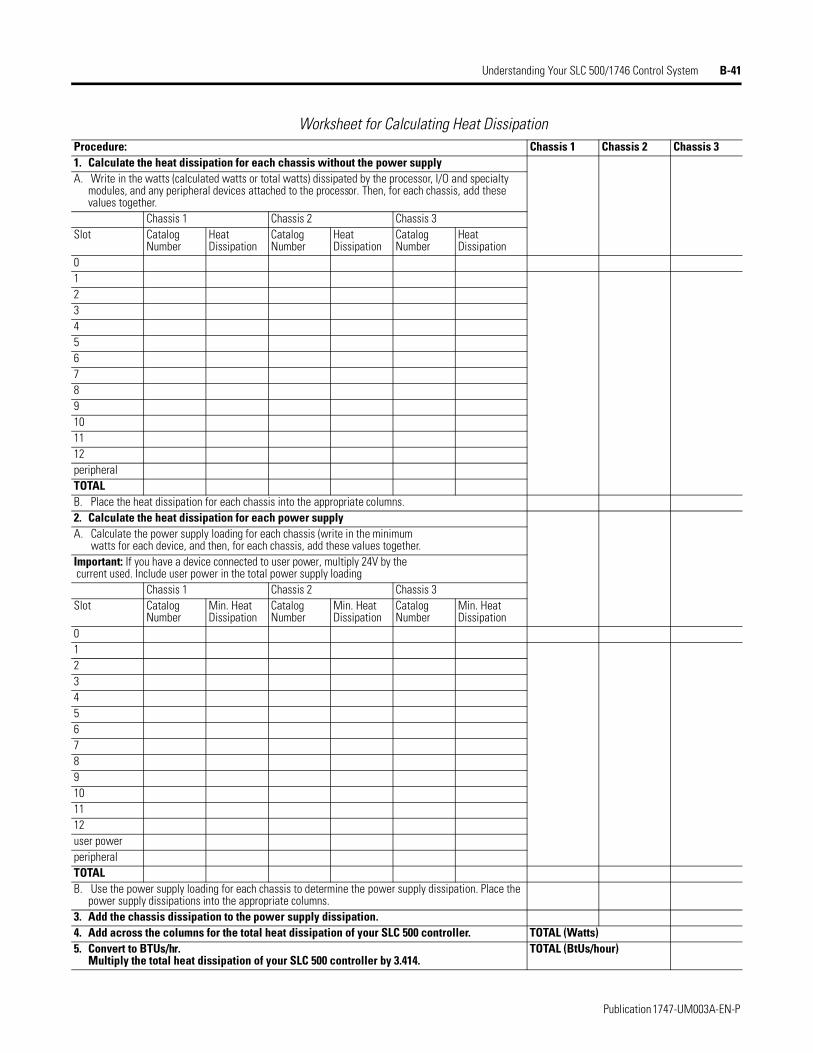
Understanding Your SLC 500/1746 Control System B-41
Worksheet for Calculating Heat DissipationProcedure: Chassis 1 Chassis 2 Chassis 31. Calculate the heat dissipation for each chassis without the power supplyA. Write in the watts (calculated watts or total watts) dissipated by the processor, I/O and specialty
modules, and any peripheral devices attached to the processor. Then, for each chassis, add these values together.
Chassis 1 Chassis 2 Chassis 3Slot Catalog
NumberHeat Dissipation
Catalog Number
Heat Dissipation
Catalog Number
Heat Dissipation
0123456789101112peripheralTOTALB. Place the heat dissipation for each chassis into the appropriate columns.2. Calculate the heat dissipation for each power supplyA. Calculate the power supply loading for each chassis (write in the minimum
watts for each device, and then, for each chassis, add these values together.Important: If you have a device connected to user power, multiply 24V by the current used. Include user power in the total power supply loading
Chassis 1 Chassis 2 Chassis 3Slot Catalog
NumberMin. Heat Dissipation
Catalog Number
Min. Heat Dissipation
Catalog Number
Min. Heat Dissipation
0123456789101112user powerperipheralTOTALB. Use the power supply loading for each chassis to determine the power supply dissipation. Place the
power supply dissipations into the appropriate columns.3. Add the chassis dissipation to the power supply dissipation.4. Add across the columns for the total heat dissipation of your SLC 500 controller. TOTAL (Watts)5. Convert to BTUs/hr.
Multiply the total heat dissipation of your SLC 500 controller by 3.414.TOTAL (BtUs/hour)
Publication 1747-UM003A-EN-P

B-42 Understanding Your SLC 500/1746 Control System
Publication 1747-UM003A-EN-P
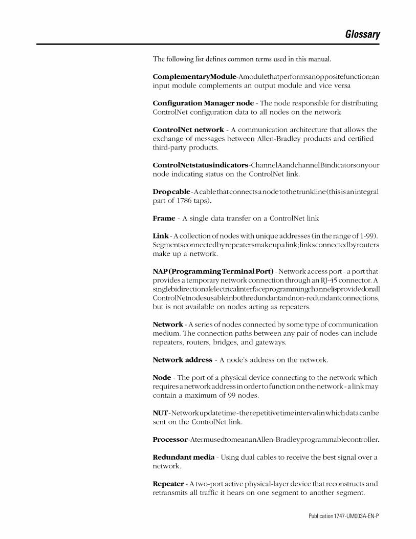
Glossary
The following list defines common terms used in this manual.
Complementary Module - A module that performs an opposite function; an input module complements an output module and vice versa
Configuration Manager node - The node responsible for distributing ControlNet configuration data to all nodes on the network
ControlNet network - A communication architecture that allows the exchange of messages between Allen-Bradley products and certified third-party products.
ControlNet status indicators - Channel A and channel B indicators on your node indicating status on the ControlNet link.
Drop cable - A cable that connects a node to the trunkline (this is an integral part of 1786 taps).
Frame - A single data transfer on a ControlNet link
Link - A collection of nodes with unique addresses (in the range of 1-99). Segments connected by repeaters make up a link; links connected by routers make up a network.
NAP (Programming Terminal Port) - Network access port - a port that provides a temporary network connection through an RJ-45 connector. A single bidirectional electrical interface programming channel is provided on all ControlNet nodes usable in both redundant and non-redundant connections, but is not available on nodes acting as repeaters.
Network - A series of nodes connected by some type of communication medium. The connection paths between any pair of nodes can include repeaters, routers, bridges, and gateways.
Network address - A node’s address on the network.
Node - The port of a physical device connecting to the network which requires a network address in order to function on the network - a link may contain a maximum of 99 nodes.
NUT - Network update time - the repetitive time interval in which data can be sent on the ControlNet link.
Processor - A term used to mean an Allen-Bradley programmable controller.
Redundant media - Using dual cables to receive the best signal over a network.
Repeater - A two-port active physical-layer device that reconstructs and retransmits all traffic it hears on one segment to another segment.
1 Publication 1747-UM003A-EN-P
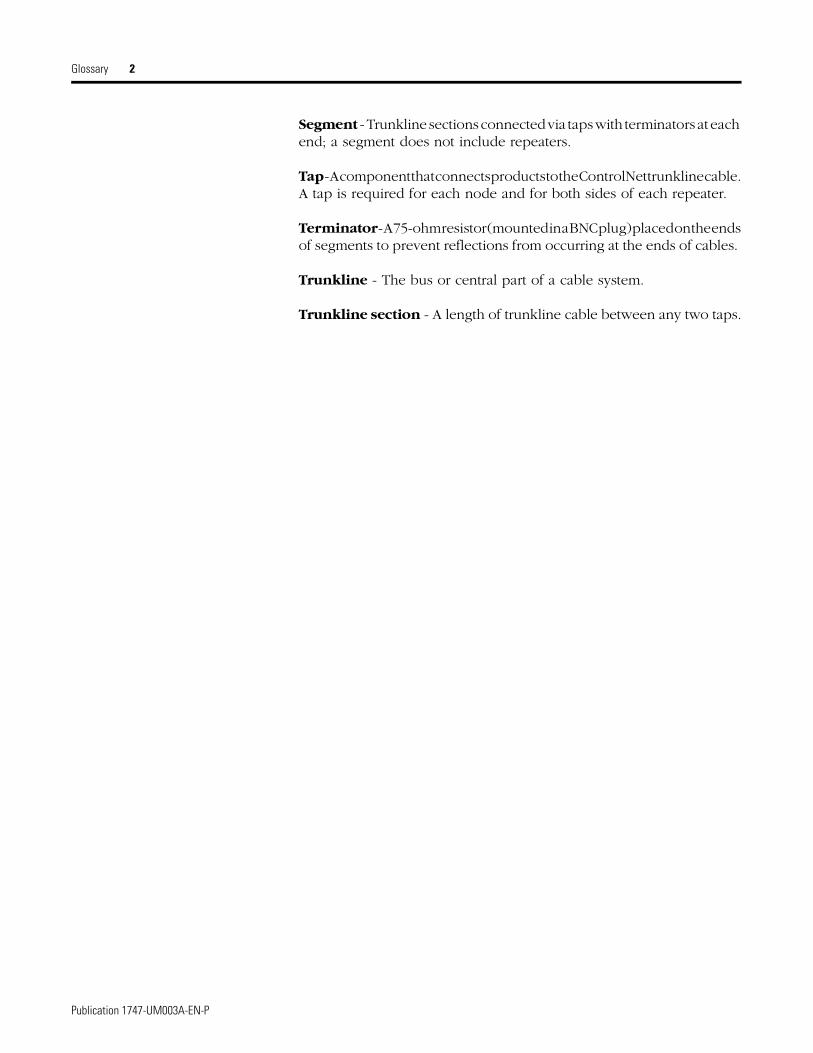
Glossary 2
Segment - Trunkline sections connected via taps with terminators at each end; a segment does not include repeaters.
Tap - A component that connects products to the ControlNet trunkline cable. A tap is required for each node and for both sides of each repeater.
Terminator - A 75-ohm resistor (mounted in a BNC plug) placed on the ends of segments to prevent reflections from occurring at the ends of cables.
Trunkline - The bus or central part of a cable system.
Trunkline section - A length of trunkline cable between any two taps.
Publication 1747-UM003A-EN-P
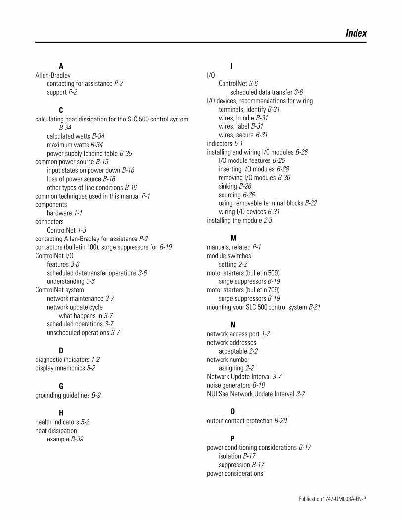
Index
AAllen-Bradley
contacting for assistance P-2support P-2
Ccalculating heat dissipation for the SLC 500 control system
B-34calculated watts B-34maximum watts B-34power supply loading table B-35
common power source B-15input states on power down B-16loss of power source B-16other types of line conditions B-16
common techniques used in this manual P-1components
hardware 1-1connectors
ControlNet 1-3contacting Allen-Bradley for assistance P-2contactors (bulletin 100), surge suppressors for B-19ControlNet I/O
features 3-6scheduled datatransfer operations 3-6understanding 3-6
ControlNet systemnetwork maintenance 3-7network update cycle
what happens in 3-7scheduled operations 3-7unscheduled operations 3-7
Ddiagnostic indicators 1-2display mnemonics 5-2
Ggrounding guidelines B-9
Hhealth indicators 5-2heat dissipation
example B-39
II/O
ControlNet 3-6scheduled data transfer 3-6
I/O devices, recommendations for wiringterminals, identify B-31wires, bundle B-31wires, label B-31wires, secure B-31
indicators 5-1installing and wiring I/O modules B-26
I/O module features B-25inserting I/O modules B-28removing I/O modules B-30sinking B-26sourcing B-26using removable terminal blocks B-32wiring I/O devices B-31
installing the module 2-3
Mmanuals, related P-1module switches
setting 2-2motor starters (bulletin 509)
surge suppressors B-19motor starters (bulletin 709)
surge suppressors B-19mounting your SLC 500 control system B-21
Nnetwork access port 1-2network addresses
acceptable 2-2network number
assigning 2-2Network Update Interval 3-7noise generators B-18NUI See Network Update Interval 3-7
Ooutput contact protection B-20
Ppower conditioning considerations B-17
isolation B-17suppression B-17
power considerations
Publication 1747-UM003A-EN-P

Index 2
common power source B-15power requirements 2-2power supplies
calculating power supply loading B-35power supply specifications B-1programming terminal
connecting to network 2-6publications, related P-1Purpose of this Manual P-1
Rrelated publications P-1relays, surge suppressors for B-19removable terminal blocks (RTB)
installing B-33removing B-32
Sscheduled datatransfer operations 3-6selecting a 1746 power supply
worksheet B-5SLC 500 system installation B-6
emergency-stop switches B-13grounding guidelines B-9master control relay B-11output contact protection B-20power conditioning considerations B-16preventing excessive heat B-8
selecting an enclosure B-6spacing your enclosures B-7special considerations B-18wiring layout B-8
special considerations B-18SLC 500 system installation
excessive line voltage variations B-18excessive noise B-18
status indicators 5-3surge suppressors
for contactor B-19for motor starters B-19for relays B-19
switch assemblies 1-3
Ttaps
connecting to network 2-4terminology G-1troubleshooting
contacting Allen-Bradley for assistance P-2troubleshooting indicators 5-1
Wwiring
I/O modules B-31wiring and grounding guidelines B-9
Publication 1747-UM003A-EN-P


Back Cover
Publication 1747-UM003A-EN-P - July 2000 2Supersedes Publication 1764-6.1 - February 1999 and 1764-6.1-DU1 - September 1999 © 2000 Rockwell International Corporation. Printed in the U.S.A.
Top Related