


Línguas
Páginas
Legal


Julho de 2012
Raquel Alexandra Abrantes Melo
Licenciada em Ciências de Engenharia Electrotécnica e de Computadores
P2P Service Exposer Architecture
Dissertação para obtenção do Grau de Mestre em Engenharia Electrotécnica e de Computadores
Orientador: Adolfo Sanchez Steiger Garção, Professor Catedrático, FCT-UNL
Co-Orientador: Pedro Miguel Negrão Maló,
Professor Assistente, FCT-UNL
Júri:
Presidente: Professor Doutor Rui Tavares Arguente: Professor Doutor Tiago Cardoso

ii
P2P Service Exposer
Copyright © Raquel Alexandra Abrantes Melo, Faculdade de Ciências e Tecnologia, Universidade
Nova de Lisboa
A Faculdade de Ciências e Tecnologia e a Universidade Nova de Lisboa têm o direito, perpétuo e
sem limites geográficos, de arquivar e publicar esta dissertação através de exemplares impressos
reproduzidos em papel ou de forma digital, ou por qualquer outro meio conhecido ou que venha a
ser inventado, e de a divulgar através de repositórios científicos e de admitir a sua cópia e
distribuição com objectivos educacionais ou de investigação, não comerciais, desde que seja dado
crédito ao autor e editor.

iii
Aos meus pais, irmã e sobrinha

iv

v
Agradecimentos
Em primeiro lugar gostaria de agradecer à pessoa mais importante da minha vida, que me fez ser
quem sou hoje, nunca desistiu de mim, fez sempre tudo o que pôde para me ajudar, mesmo que
isso a prejudicasse, e me deu a felicidade de ser tia, a minha irmã, Mariana.
Aos meus pais, pelo enorme esforço realizado, para que eu nunca tivesse de me preocupar com
outra coisa sem ser estudar, por todos os momentos de preocupação e apoio, por me terem
deixado ser eu própria mesmo quando não concordaram comigo.
Às minhas queridas amigas Raquel e Maria João, por tudo o que são, pelos risos, pelos choros,
por estarmos juntas desde sempre e para sempre.
Ao Bruno Caixinha por tudo o que vivemos juntos no decorrer deste curso, por ter sido o meu
colega mais fiel, o meu melhor amigo e por todo o seu amor e carinho.
Ao Pedro Maló por me ter possibilitado realizar este trabalho neste grupo, pela ajuda e pela
orientação dada na realização desta tese. Ao Bruno Almeida, pela sua dedicação, esforço e
empenho para que eu me tornasse uma pessoa melhor.
Ao Pedro Gomes de Oliveira pelas confidências, ao Gonçalo Azevedo por ter sido a pessoa que
me apresentou ao mundo FCT, ao Bruno Duarte pelas risadas, ao Pedro Almeida por tantos
momentos, ao David Aleixo pela lealdade, ao Hugo Pereira pelas conversas demoradas, à
Vanessa Chamorrinha por ter sido a minha rapariga. Ao Pedro Bueno e Diogo Pinto, pela diversão
e amizade. Aos meus colegas do GRIS, Márcio Mateus e Tiago Teixeira por nunca se terem
negado a ajudar.
A todos os que me acompanharam e que não são referidos, mas que não serão esquecidos.
O meu sincero, Obrigado

vi

vii
Abstract
Smart homes were developed to improve inhabitants comfort by integrating electronic devices that
perform the control of domestic activities, such as home entertainment systems, yard watering,
house cleaning, etc. They are equipped with sensors and actuators that rely on P2P networking to
share services and resources amongst them. To perform home management, inhabitants want to
access their homes, from anywhere in the world using everyday devices, like smartphones. These
devices aren’t peers of the network. They are outsiders that use a technology different, accessing
the in-house P2P networks through Service Exposers, a special set of peers that expose the
services available in the P2P network. Expose the services is challenging, because services in the
network are always changing, new services can appear and the existing can change their locations
and methods. These peers use a different technology; non-standard and inaccessible by devices
like smartphones. For this, a P2P Service Exposer architecture is proposed, that indexes all the
services available in the network, expose them to clients in a standardized platform, such as Web
Services, and perform translations between the two different technological environments.
Keywords: Services, P2P Network, Indexation, Invocation, Translation and Exposition

viii

ix
Resumo
Casas inteligentes foram desenvolvidas para melhorar o conforto dos seus habitantes, integrando
dispositivos electrónicos que realizam o controlo de atividades domésticas, tais como, sistemas
de entretenimento, irrigação de quintais, limpeza de casas, etc. Estas estão equipadas com
sensores e actuadores que dependem de redes P2P para compartilhar serviços e recursos entre
si. Para executar a gestão da casa, os habitantes desejam aceder às mesmas, de qualquer parte
do mundo usando aparelhos do dia-a-dia, tais como smartphones. Estes dispositivos não são nós
da rede. Estes estão do lado de fora e usam uma tecnologia diferente, acedendo às redes P2P
caseiras através de expositores de serviços, um conjunto especial de nós, que expõem os
serviços disponíveis na rede P2P. Expor os serviços é desafiante, porque os serviços da rede
estão sempre a mudar, novos serviços podem aparecer e os existentes podem mudar as suas
localizações e métodos. Estes nós usam uma tecnologia diferente, não-standard e inacessível
através de dispositivos como smartphones. Para isso, uma arquitetura de Exposição de Serviços
P2P é proposta, que indexa todos os serviços disponíveis na rede, os expõe a clientes através de
uma plataforma standardizada, como Web Services, e executam traduções entre os dois
diferentes ambientes tecnológicos.
Palavras-Chave: Serviços, Rede P2P, Indexação, Invocação, Tradução e Exposição

x
xi
Index
Chapter 1 - Introduction ............................................................................................................................................ 1
1.1. Motivation Scenario: Domotics ................................................................................................................. 1
1.2. Problematic ............................................................................................................................................... 3
1.3. Work Methodology .................................................................................................................................... 5
1.4. Dissertation Outline ................................................................................................................................... 7
Chapter 2 - State-of-the-Art ...................................................................................................................................... 9
2.1. Review ...................................................................................................................................................... 9
2.2. Individual Review .................................................................................................................................... 10
2.3. Synthesis ................................................................................................................................................ 15
2.4. Advancement .......................................................................................................................................... 16
Chapter 3 - P2P Service Exposer Architecture ....................................................................................................... 19
3.1. Concept ................................................................................................................................................... 19
3.2. Architecture Overview ............................................................................................................................. 20
3.3. Architecture Logical Modules .................................................................................................................. 21
3.3.1. Service Exposition ............................................................................................................................... 23
3.3.2. Service Invocation Orchestration ........................................................................................................ 25
3.3.3. Translation of Services ........................................................................................................................ 26
3.3.4. Indexation of Available Services ......................................................................................................... 27
3.3.5. P2P Connection .................................................................................................................................. 28
3.4. Architecture Composition ........................................................................................................................ 29
3.5. Architecture Module Sequence ............................................................................................................... 30
3.5.1. Indexation of Services ......................................................................................................................... 30
3.5.2. Invoke Service ..................................................................................................................................... 31
Chapter 4 - Testing and Validation ......................................................................................................................... 33
4.1. Testing Methodology ............................................................................................................................... 33
4.2. Proof of Concept Implementation ........................................................................................................... 35
4.3. Test Definition and Execution ................................................................................................................. 36
4.3.1. Invocation of Services ......................................................................................................................... 37
4.3.2. Indexation of Services ......................................................................................................................... 38
4.4. Verdict ..................................................................................................................................................... 41
Chapter 5 - Conclusions and Future Work .............................................................................................................. 43
5.1. Conclusions ............................................................................................................................................ 43
5.2. Future Work ............................................................................................................................................ 46
Chapter 6 - Bibliography ......................................................................................................................................... 47

xii

xiii
Index of Figures
Figure 1.1 - Home Network System .......................................................................................................................... 2
Figure 1.2 - Work methodology ................................................................................................................................. 5
Figure 2.1 - Proposed architecture for DLNA Multimedia Sharing System (Lai, Huang et al. 2010) ...................... 10
Figure 2.2 - FileStore Peers across VO (Sobolewski, Soorianarayanan et al. 2003) ............................................. 12
Figure 2.3 - Inter-OSGI interaction via Web Services bundle (Wu, Liao et al. 2007) .............................................. 13
Figure 2.4 - BOSS Architecture (Song, Kim et al. 2005) ......................................................................................... 14
Figure 3.1 - Concept ............................................................................................................................................... 19
Figure 3.2 - P2P Service Exposer Architecture ...................................................................................................... 21
Figure 3.3 - Entry Interface Representation ............................................................................................................ 22
Figure 3.4 - Exit Interface Representation .............................................................................................................. 22
Figure 3.5 - Service Exposition logical module ....................................................................................................... 24
Figure 3.6 - Service Invocation Orchestration module ............................................................................................ 25
Figure 3.7 - Translation of Services module ........................................................................................................... 26
Figure 3.8 - Indexation of Available Services module ............................................................................................. 27
Figure 3.9 - P2P Connection module ...................................................................................................................... 28
Figure 3.10 - Architecture Composition .................................................................................................................. 29
Figure 3.11 - Sequence Diagram - Indexation of Services ..................................................................................... 31
Figure 3.12 - Sequence Diagram - Invoke Service ................................................................................................. 32
Figure 4.1 - Testing Process ................................................................................................................................... 33
Figure 4.2 - Invocation of Services: Test Initial Conditions ..................................................................................... 38
Figure 4.3 - Create Service Test ............................................................................................................................. 39

xiv
Figure 4.4 - Disable Service Test ........................................................................................................................... 40
Figure 4.5 - Maintain Service .................................................................................................................................. 40
Figure 4.6 - Change Service Location Test ............................................................................................................ 40
xv
Index of Tables
Table 2.1 - Overview of the State of the Art Research ........................................................................................... 16
Table 4.1 – Example of a TTCN based test table ................................................................................................... 34
Table 4.2 - Test Case Example .............................................................................................................................. 35
Table 4.3 - Invocation of Services: Test Definition .................................................................................................. 37
Table 4.4 - Invocation of Services: Text Execution ................................................................................................. 38
Table 4.5 - Indexation of Services: Test Definition ................................................................................................. 39
Table 4.6 - Indexation of Services: Test Execution ................................................................................................. 41

xvi
xvii
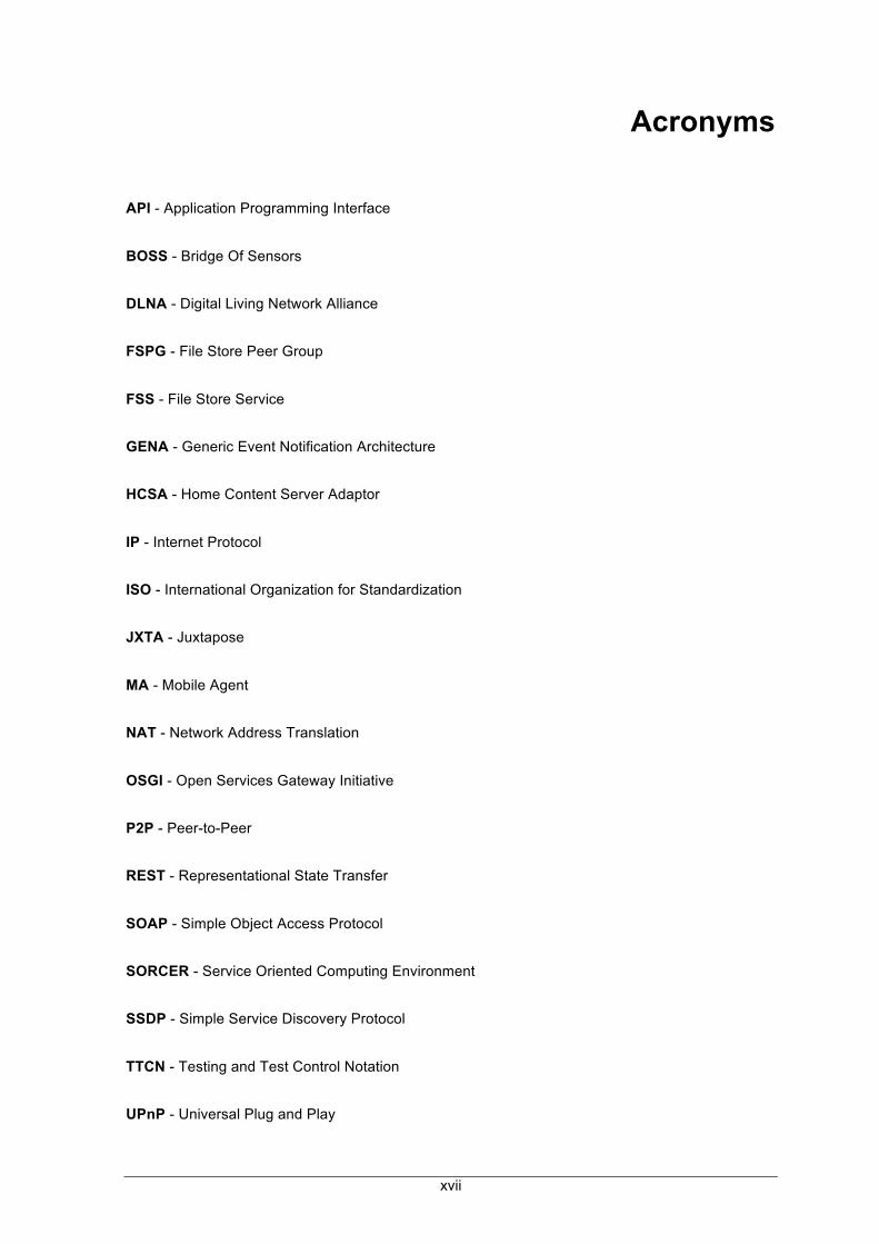
Acronyms
API - Application Programming Interface
BOSS - Bridge Of Sensors
DLNA - Digital Living Network Alliance
FSPG - File Store Peer Group
FSS - File Store Service
GENA - Generic Event Notification Architecture
HCSA - Home Content Server Adaptor
IP - Internet Protocol
ISO - International Organization for Standardization
JXTA - Juxtapose
MA - Mobile Agent
NAT - Network Address Translation
OSGI - Open Services Gateway Initiative
P2P - Peer-to-Peer
REST - Representational State Transfer
SOAP - Simple Object Access Protocol
SORCER - Service Oriented Computing Environment
SSDP - Simple Service Discovery Protocol
TTCN - Testing and Test Control Notation
UPnP - Universal Plug and Play

xviii
VDM - Vienna Development Method
VO - Virtual Organisation
WAN - Wide Area Network
XML - Extensible Markup Language

Chapter 1 - Introduction 1.1 Motivation Scenario: Domotics
1
Chapter 1 - Introduction
1.1. Motivation Scenario: Domotics
Evolution has occurred faster than the ability of people to keep up with it. The technology has
reached everything, everywhere. Smaller devices able to support higher functionalities became
faster, easier, cheaper, and most reachable to everyone that wants take advantage of the
technology. Our homes started to be a distributed system of potentially collaborating hosts (Aiello
and Dustdar 2008), with the technology being no longer used for only the repetitive tasks that
humans don’t want to do.
A smart home or a home automation system integrates electronic devices in a house among
themselves. The techniques employed in home automation include those in building automation as
well as the control of domestic activities, such as home entertainment systems, houseplant, yard
watering, house cleaning and domestic robots, among others. The devices inside the home
systems have become networked and are enabled with the possibility of accessing the Internet to
facilitate and enrich our daily activities (Bottaro and Gérodolle 2008).
Sensors and actuators, which are small devices, easily damaged with poor autonomy, compose
the network responsible for managing our homes. Due to their inherent characteristics they lead to
some reliability issues. If the network were implemented in a centralized model, putting all the
workload in the “server sensor”, in case of its failure, the entire network will be doomed. Working in
a distributed way, allowing the devices to share resources, services and information with each
other will permit that if one of the elements fails, the whole network will not be compromised
(Parameswaran, Susarla et al. 2001).
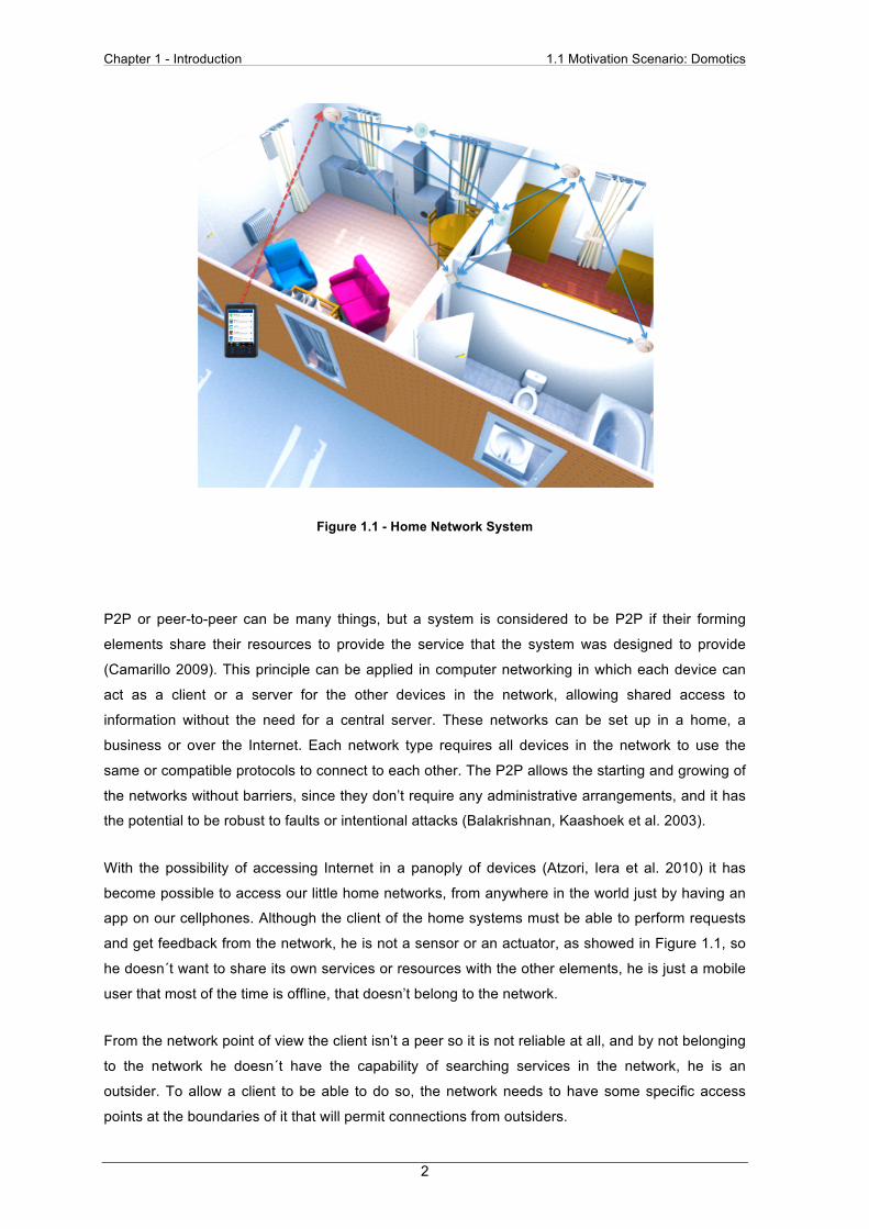
An example of a home network system is showed in Figure 1.1, where sensors share information
with each other inside the decentralized network, allowing the outside users to get information from
the network using his smartphone, accessing the network through an app.
Chapter 1 - Introduction 1.1 Motivation Scenario: Domotics
2
Figure 1.1 - Home Network System
P2P or peer-to-peer can be many things, but a system is considered to be P2P if their forming
elements share their resources to provide the service that the system was designed to provide
(Camarillo 2009). This principle can be applied in computer networking in which each device can
act as a client or a server for the other devices in the network, allowing shared access to
information without the need for a central server. These networks can be set up in a home, a
business or over the Internet. Each network type requires all devices in the network to use the
same or compatible protocols to connect to each other. The P2P allows the starting and growing of
the networks without barriers, since they don’t require any administrative arrangements, and it has
the potential to be robust to faults or intentional attacks (Balakrishnan, Kaashoek et al. 2003).
With the possibility of accessing Internet in a panoply of devices (Atzori, Iera et al. 2010) it has
become possible to access our little home networks, from anywhere in the world just by having an
app on our cellphones. Although the client of the home systems must be able to perform requests
and get feedback from the network, he is not a sensor or an actuator, as showed in Figure 1.1, so
he doesn´t want to share its own services or resources with the other elements, he is just a mobile
user that most of the time is offline, that doesn’t belong to the network.
From the network point of view the client isn’t a peer so it is not reliable at all, and by not belonging
to the network he doesn´t have the capability of searching services in the network, he is an
outsider. To allow a client to be able to do so, the network needs to have some specific access
points at the boundaries of it that will permit connections from outsiders.
Chapter 1 - Introduction 1.2 Problematic
3
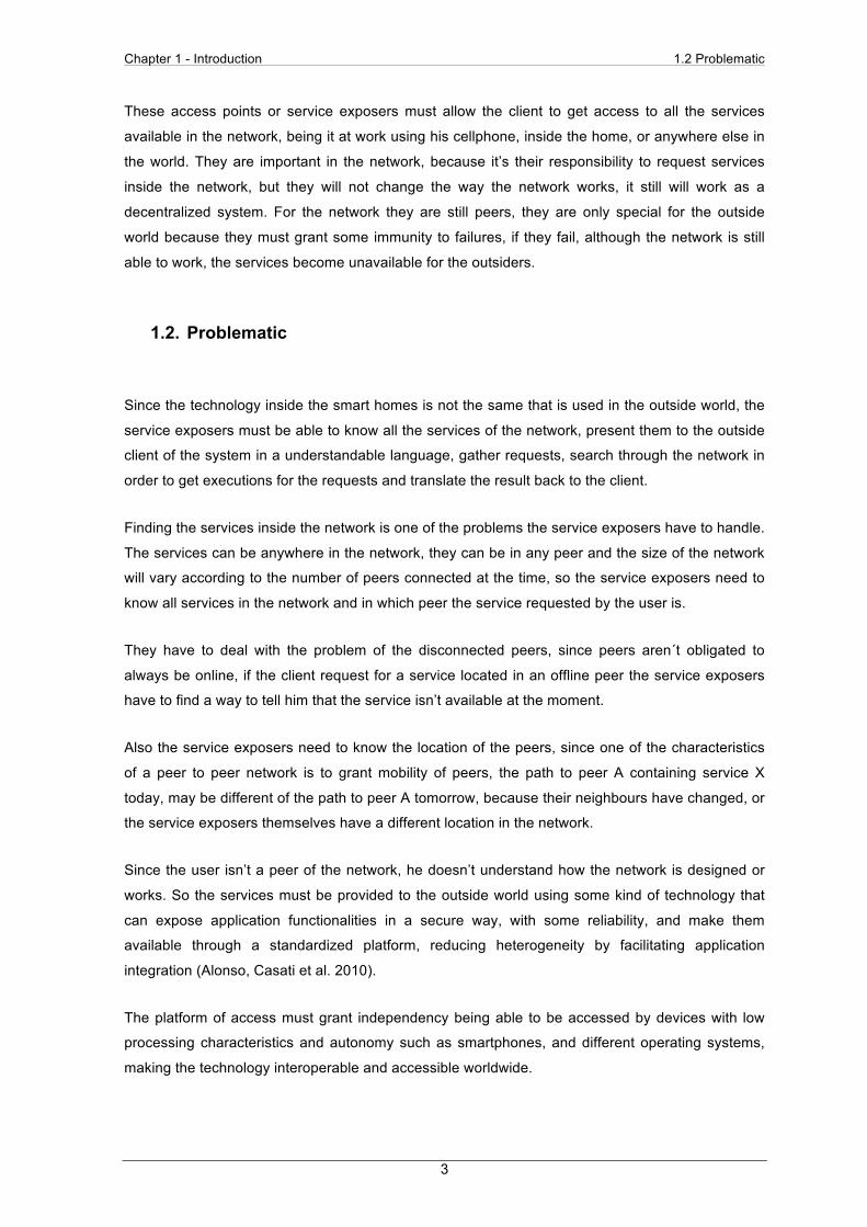
These access points or service exposers must allow the client to get access to all the services
available in the network, being it at work using his cellphone, inside the home, or anywhere else in
the world. They are important in the network, because it’s their responsibility to request services
inside the network, but they will not change the way the network works, it still will work as a
decentralized system. For the network they are still peers, they are only special for the outside
world because they must grant some immunity to failures, if they fail, although the network is still
able to work, the services become unavailable for the outsiders.
1.2. Problematic
Since the technology inside the smart homes is not the same that is used in the outside world, the
service exposers must be able to know all the services of the network, present them to the outside
client of the system in a understandable language, gather requests, search through the network in
order to get executions for the requests and translate the result back to the client.
Finding the services inside the network is one of the problems the service exposers have to handle.
The services can be anywhere in the network, they can be in any peer and the size of the network
will vary according to the number of peers connected at the time, so the service exposers need to
know all services in the network and in which peer the service requested by the user is.
They have to deal with the problem of the disconnected peers, since peers aren´t obligated to
always be online, if the client request for a service located in an offline peer the service exposers
have to find a way to tell him that the service isn’t available at the moment.
Also the service exposers need to know the location of the peers, since one of the characteristics
of a peer to peer network is to grant mobility of peers, the path to peer A containing service X
today, may be different of the path to peer A tomorrow, because their neighbours have changed, or
the service exposers themselves have a different location in the network.
Since the user isn’t a peer of the network, he doesn’t understand how the network is designed or
works. So the services must be provided to the outside world using some kind of technology that
can expose application functionalities in a secure way, with some reliability, and make them
available through a standardized platform, reducing heterogeneity by facilitating application
integration (Alonso, Casati et al. 2010).
The platform of access must grant independency being able to be accessed by devices with low
processing characteristics and autonomy such as smartphones, and different operating systems,
making the technology interoperable and accessible worldwide.
Chapter 1 - Introduction 1.2 Problematic
4
The service exposers have to know all the information about the services available, so that if one of
them is offline, the services can still be exposed. Also the client must not be obligated to access the
network using always the same exposer. If these issues are considered, no centralization is
introduced in the system. This is the second problem that the service exposers have to handle, the
services from the inside network must be deployed to the outside user in a standardized way, using
another technology different from P2P, that still will keep the system decentralized.
In the context of the previous problem another one will arise. Since there are different technologies
between the inside network and the outside world, the service exposers must grant translation from
P2P to the other technology used. They have to decode the requests done by the client, transform
them into P2P language in order to query the requests in the network, handling the wait time of
searching the network for the service and receive a response. Finally they have to code the
response back to the language that the user understands.
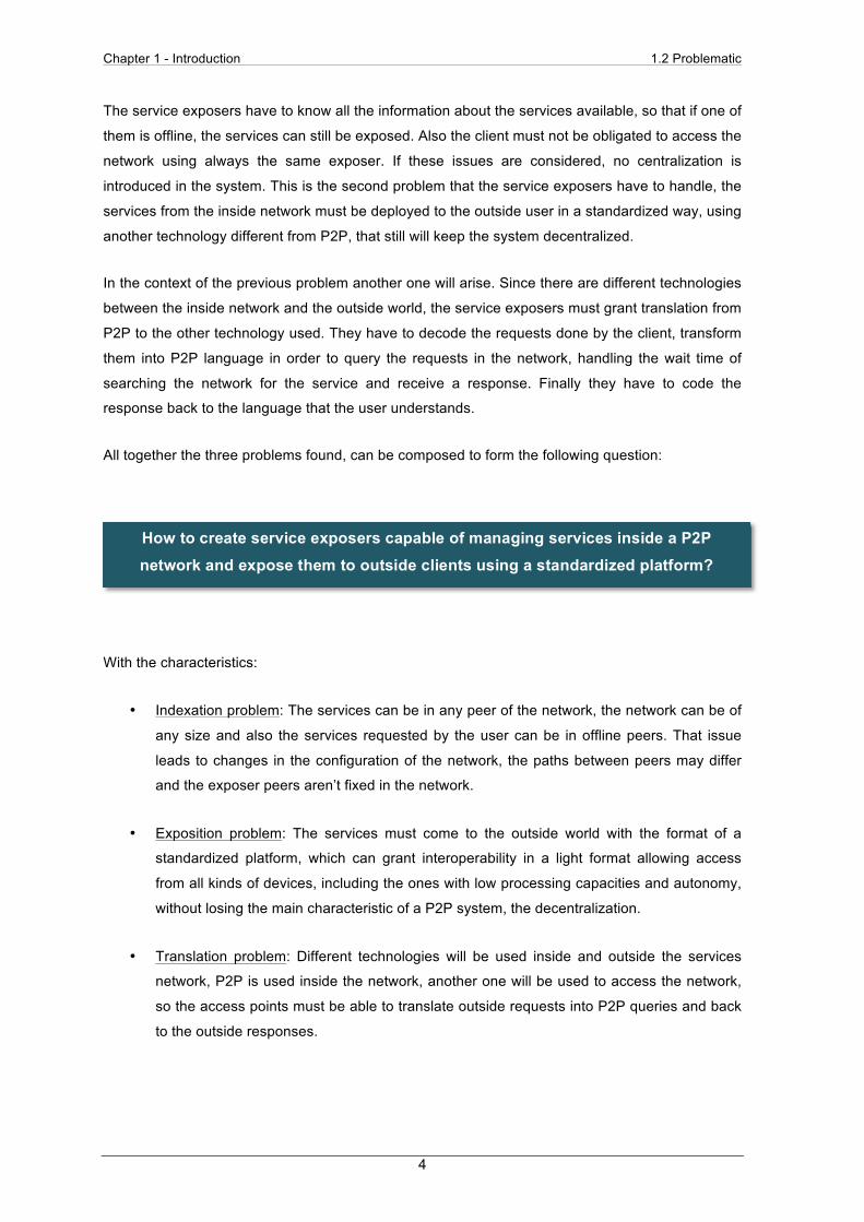
All together the three problems found, can be composed to form the following question:
With the characteristics:
• Indexation problem: The services can be in any peer of the network, the network can be of
any size and also the services requested by the user can be in offline peers. That issue
leads to changes in the configuration of the network, the paths between peers may differ
and the exposer peers aren’t fixed in the network.
• Exposition problem: The services must come to the outside world with the format of a
standardized platform, which can grant interoperability in a light format allowing access
from all kinds of devices, including the ones with low processing capacities and autonomy,
without losing the main characteristic of a P2P system, the decentralization.
• Translation problem: Different technologies will be used inside and outside the services
network, P2P is used inside the network, another one will be used to access the network,
so the access points must be able to translate outside requests into P2P queries and back
to the outside responses.
How to create service exposers capable of managing services inside a P2P network and expose them to outside clients using a standardized platform?
Chapter 1 - Introduction 1.3 Work Methodology
5
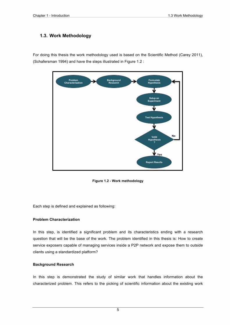
1.3. Work Methodology
For doing this thesis the work methodology used is based on the Scientific Method (Carey 2011),
(Schafersman 1994) and have the steps illustrated in Figure 1.2 :
Figure 1.2 - Work methodology
Each step is defined and explained as following:
Problem Characterization
In this step, is identified a significant problem and its characteristics ending with a research
question that will be the base of the work. The problem identified in this thesis is: How to create
service exposers capable of managing services inside a P2P network and expose them to outside
clients using a standardized platform?
Background Research
In this step is demonstrated the study of similar work that handles information about the
characterized problem. This refers to the picking of scientific information about the existing work
Setup an Experiment
Formulate Hypothesis
Test Hypothesis
Valid Hypothesis
?
Report Results
Yes
No
Background Research
Problem Characterization
Chapter 1 - Introduction 1.3 Work Methodology
6
that handles the management of services inside a network and exposes them through a
standardized platform.
Formulate Hypothesis
Based on the background research the hypothesis must bring clarity, specificity and explain a
solution that answers the problem characteristics so that it can be solved. In this thesis, it is
required that the hypothesis focuses on the problem of searching and exposing P2P services
through a standardized platform.
Setup an Experiment
In the case of this thesis the setting up of experiments refers to the creation of a technological
architecture for searching and exposing P2P services through a standardized platform. Since the
hypothesis must be validated, it is necessary to set up an implementation of a proof of concept.
Test Hypothesis
At first a test set must be defined according to the characteristics of the problem and the formulated
hypothesis. It is necessary to evaluate the outcomes of the architecture designed in order to
evaluate the hypothesis proposed, so it have to be tested using the designed experimentation. For
each test, data outputs should be collected for further analysis and hypothesis validation. After the
application of all tests and data outputs collected, the results are interpreted and if applicable,
qualitative and quantitative data analysis should be applied to the result.
Validate Hypothesis
After observing the results of the testing process, it is necessary to verify the validity of the
hypothesis proposed. Validation needs to take into account the characteristics of the problem. The
results can empower the hypothesis created or tear down all the work done so far, leading to the
making of a new hypothesis and therefore the remake of work since step 3.
Report Results
After the positive results, is possible to consider work valid and define the recommendations for
further research. The outcome should result in a contribution to the scientific community, scientific
papers should be written to present the consolidate results and should be finalised with a
dissertation about the hypothesis, such as this document.
Chapter 1 - Introduction 1.4 Dissertation Outline
7
1.4. Dissertation Outline
Besides this chapter, that have already been presented, the remainder of this dissertation is
divided in another four, with each one having the following characteristics:
State-of-the-Art: The second chapter presents the related work elements studied, which are
systems capable of managing services and expose them to outside clients. Also all the systems
are analysed taking in concern the characteristics of the problem previously defined. At the end of
the chapter in the advancement section the characteristics exploited in the creation of the system
architecture.
P2P Service Exposer Architecture: The third chapter presents the architecture created to support
the P2P service exposer. At first, the concept behind the architecture created is presented, then
are presented and defined the three logical layers of the architecture with its five logical modules
and their interfaces explained. It’s showed a detailed architecture with the layers, logical modules
and interfaces exposed, and the chapter ends with the chaining of the different logical modules.
Testing and Validation: The fourth chapter presents the tests used to validate the formulated
hypothesis. At first is done the description of the methodology adopted to test the hypothesis. Also
a description of the implemented proof of concept and the tests definition and execution is made.
The results of the tests are then presented and through its analysis is verified if the initial objectives
were achieved.
Conclusions and Future Work: The fifth and final chapter presents a summary of this
dissertation, highlighting the most important aspects of the work developed. It also takes in concern
the results obtained with the realization of the testing process, and is pointed a direction for future
research.

Chapter 1 - Introduction 1.4 Dissertation Outline
8

Chapter 2 - State-of-the-Art 2.1 Review
9
Chapter 2 - State-of-the-Art
2.1. Review
One way to help us solve our problems is to see how others solved problems related with ours. So
a research was made, in the development of this thesis in order to discover similar systems,
technologies and approaches that can handle the problem of managing services in a network and
exposing them through a standardized platform.
The research was made keeping in focus the P2P networks since the system needs to be a
decentralized system, the ease of access, in order to allow the system to be accessed from
different kinds of users, and see if with this relation translation are performed between the
technology of search and the technology of exposure.
The systems studied, presented in alphabetic order are:
• DLNA-Based Multimedia Sharing System for OSGI Framework With Extension to P2P
Network (Lai, Huang et al. 2010): This system mixes between DLNA and P2P for sharing
multimedia inside the home network and OSGI and P2P for sharing multimedia in the
outside world. Its architecture is one of the reasons why this system and the possibility of
OSGI as a standardized platform for the exposition.
• Service-Oriented File Sharing (Sobolewski, Soorianarayanan et al. 2003): It uses P2P
technology to deploy and search documents. Proprietary application is the interface for to
client interactions. The way this system distribute the information for the services inside the
P2P network, is the reason why it was studied.
• Service-Oriented Smart-Home Architecture Based on OSGI and Mobile-Agent Technology
(Wu, Liao et al. 2007): It uses a P2P based approach to manage their mobile agents and
SOAP to deliver the mobile agents between the platforms. This approach was the reason
of studying the system.
• UPnP-Based Sensor Network Management Architecture (Song, Kim et al. 2005): Although
P2P is not used in this system, protocols like SOAP are used to expose the services of the
sensor network, granting standardization. The main reason of studying this system is the
way that it performs translation between technologies.

Chapter 2 - State-of-the-Art 2.2 Individual Review
10
After giving a resume of each technology characteristics a full detailed explanation is showed in the
next section. In the section 2.3 a synthesis of all the analysed technologies is presented. By last,
their contributions for this work are presented in section 2.4.
2.2. Individual Review
DLNA-Based Multimedia Sharing System for OSGI Framework With Extension to P2P
Network
In this project a Digital Living Network Alliance (Alliance,D.L.N. 2012)-based multimedia sharing
system for OSGI framework with extension to P2P network is proposed, so that users can access
multimedia resources in a P2P network via DLNA and P2P users can apply network mechanisms
in OSGI bundles to access shared DLNA multimedia resource in home networks. The composition
of the architecture is:
• A Service Provider Server, which is responsible for managing the network framework,
keeping database content updated in real time and provide the latest information to users.
• A Home Content Server Adapter, that is responsible for the communication between the
home network and the WAN.
• A P2P Server that can be any node in the network and can share multimedia to all users
in the P2P network automatically.
• A P2P Client that provides the file to the end users.
• A DLNA Server that works like the P2P Server but inside the home network.
• A DLNA Client that is the consumer of the multimedia file inside the home network.
An example of the architecture is showed in Figure 2.1.
Figure 2.1 - Proposed architecture for DLNA Multimedia Sharing System (Lai, Huang et al. 2010)
Wide Area Network
P2P Server
P2P Server P2P Client
P2P Client
DLNA Server
DLNA Player DLNA Server
DLNA Player
Home Network
Service Provider Server Home Content Server Adapter
Chapter 2 - State-of-the-Art 2.2 Individual Review
11
Analysis
In this project it seems that the goal was to create a hybrid P2P network, since it exist centralization
in all the sets of the network. In the WAN it happens with the use of a Service Provider Server
responsible for the management and maintenance of a database with the multimedia data that the
P2P servers and HCSA have to share. Inside the home network the same process occur between
DLNA players and servers, and also from this network to the outside world, since all the multimedia
information have to pass by the HCSA. Also, the communication isn’t done directly among peers.
No translation of information is required in this kind of system, since it is used a previously defined
protocol, but the HCSA have the responsibility of acting as a NAT(Systems 2011), changing the IP
of the inside DLNA Servers to the outside clients and act as a DLNA Server inside the home
network, for the inside DLNA Clients.
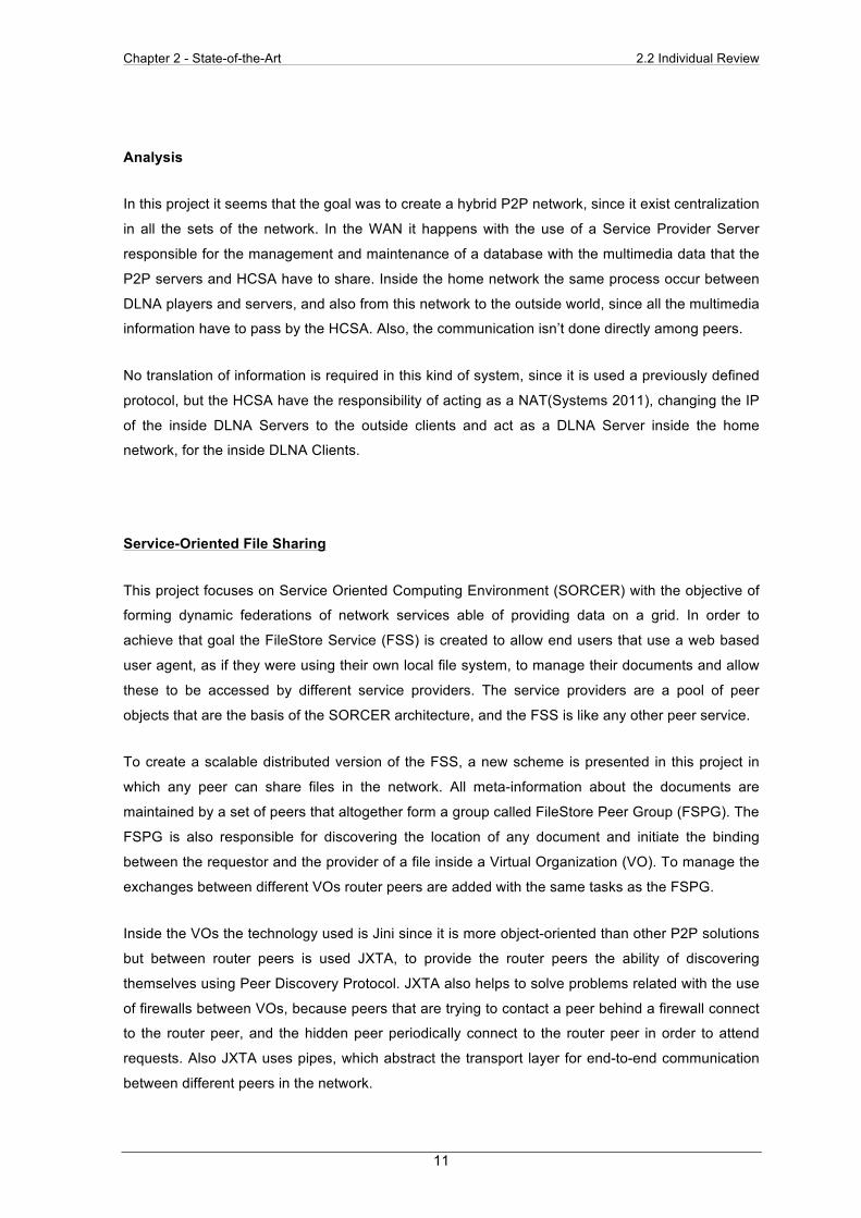
Service-Oriented File Sharing
This project focuses on Service Oriented Computing Environment (SORCER) with the objective of
forming dynamic federations of network services able of providing data on a grid. In order to
achieve that goal the FileStore Service (FSS) is created to allow end users that use a web based
user agent, as if they were using their own local file system, to manage their documents and allow
these to be accessed by different service providers. The service providers are a pool of peer
objects that are the basis of the SORCER architecture, and the FSS is like any other peer service.
To create a scalable distributed version of the FSS, a new scheme is presented in this project in
which any peer can share files in the network. All meta-information about the documents are
maintained by a set of peers that altogether form a group called FileStore Peer Group (FSPG). The
FSPG is also responsible for discovering the location of any document and initiate the binding
between the requestor and the provider of a file inside a Virtual Organization (VO). To manage the
exchanges between different VOs router peers are added with the same tasks as the FSPG.
Inside the VOs the technology used is Jini since it is more object-oriented than other P2P solutions
but between router peers is used JXTA, to provide the router peers the ability of discovering
themselves using Peer Discovery Protocol. JXTA also helps to solve problems related with the use
of firewalls between VOs, because peers that are trying to contact a peer behind a firewall connect
to the router peer, and the hidden peer periodically connect to the router peer in order to attend
requests. Also JXTA uses pipes, which abstract the transport layer for end-to-end communication
between different peers in the network.

Chapter 2 - State-of-the-Art 2.2 Individual Review
12
An example of the framework is showed in Figure 2.2.
Figure 2.2 - FileStore Peers across VO (Sobolewski, Soorianarayanan et al. 2003)
Analysis
With the creation of the FSPG, finding the services inside the network isn´t a problem, this special
set of peers are responsible of knowing all the documents available in the network and perform the
binding between requester and provider inside the VOs, as if the user was using its local file
system, and they can leave or join the FSPG without restrictions, since the information will be
replicated to other peers in the group.
Assuming that the FSPG is a fixed group of peers set at one of the boundaries of the network,
although inside the group the peers are mobile, the path to the group of peers will always be the
same, that characteristic will allow the connection between router peers both inside and outside of
the VO but doesn´t grant mobility of the peers, the FSS peers are obligated to join the group when
they are online, so they have to know the location of the group.
Service-Oriented Smart-Home Architecture Based on OSGI and Mobile-Agent Technology
In this project a Service Oriented Architecture is proposed for smart-homes, based on Open
Services Gateway Initiative (Alliance,O. 2012) (OSGI) and Mobile Agent (MA) technologies in order
to provide appropriate services and deal with the dynamic environment problem, which is a
consequence of the access done by mobile devices to smart-homes. It is a P2P architecture model
based on multiple OSGI platforms, in which service-oriented mechanisms are used for interaction
between system components and MA is used to improve this interaction.
Provider Peers
Router Peers
FileStore Peers
Virtual FS Peer Group Subnet
1 2
3 4
5
6 1. Request for a file based on DocumentDescriptor 2,3. FS Peers resolves the location of the requested file 4. Binding Initiated 5. Reference of the location peer returned 6. File Downloaded via stream
Chapter 2 - State-of-the-Art 2.2 Individual Review
13
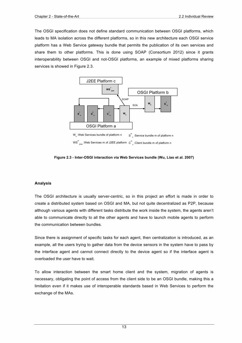
The OSGI specification does not define standard communication between OSGI platforms, which
leads to MA isolation across the different platforms, so in this new architecture each OSGI service
platform has a Web Service gateway bundle that permits the publication of its own services and
share them to other platforms. This is done using SOAP (Consortium 2012) since it grants
interoperability between OSGI and not-OSGI platforms, an example of mixed platforms sharing
services is showed in Figure 2.3.
Figure 2.3 - Inter-OSGI interaction via Web Services bundle (Wu, Liao et al. 2007)
Analysis
The OSGI architecture is usually server-centric, so in this project an effort is made in order to
create a distributed system based on OSGI and MA, but not quite decentralized as P2P, because
although various agents with different tasks distribute the work inside the system, the agents aren’t
able to communicate directly to all the other agents and have to launch mobile agents to perform
the communication between bundles.
Since there is assignment of specific tasks for each agent, then centralization is introduced, as an
example, all the users trying to gather data from the device sensors in the system have to pass by
the interface agent and cannot connect directly to the device agent so if the interface agent is
overloaded the user have to wait.
To allow interaction between the smart home client and the system, migration of agents is
necessary, obligating the point of access from the client side to be an OSGI bundle, making this a
limitation even if it makes use of interoperable standards based in Web Services to perform the
exchange of the MAs.
J2EE Platform c
WS1
j2ee OSGI Platform b
Wb S1
b
Wa C1
a S2
a S1
a
OSGI Platform a
SOAP
SOAP
Wn :Web Services bundle of platform n
WSm
j2ee :Web Services m of J2EE platform
Sm
n :Service bundle m of platform n
Cm
n :Client bundle m of platform n
Chapter 2 - State-of-the-Art 2.2 Individual Review
14
UPnP-Based Sensor Network Management Architecture
In this project a management framework for sensor networks is proposed, it uses UPnP(Play 2012)
architecture since its main functionalities are automatic device and service discovery, device
control and event processing by using XML-based messages such as Simple Service Discovery
Protocol (SSDP) for the service management, Simple Object Access Protocol (SOAP) for the
control management and Generic Event Notification Architecture (GENA) for the event
management.
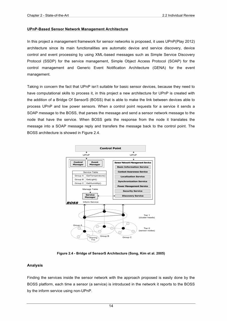
Taking in concern the fact that UPnP isn’t suitable for basic sensor devices, because they need to
have computational skills to process it, in this project a new architecture for UPnP is created with
the addition of a Bridge Of SensorS (BOSS) that is able to make the link between devices able to
process UPnP and low power sensors. When a control point requests for a service it sends a
SOAP message to the BOSS, that parses the message and send a sensor network message to the
node that have the service. When BOSS gets the response from the node it translates the
message into a SOAP message reply and transfers the message back to the control point. The
BOSS architecture is showed in Figure 2.4.
Figure 2.4 - Bridge of SensorS Architecture (Song, Kim et al. 2005)
Analysis
Finding the services inside the sensor network with the approach proposed is easily done by the
BOSS platform, each time a sensor (a service) is introduced in the network it reports to the BOSS
by the inform service using non-UPnP.
!"#$%&'((!)*&%+,",%-.&/!01)$2%-1&/).(*.!"%3"-%()1&1"*3*.!"2%45./5% "11-% 6'/5% #1&&% /!6('*3*.!"3#% 177!)*% *53"% +,",%/!"*)!#% 3"-% 101"*."89% :"% *51% ;."-).!"% &$&*162% *51% <303%3((#1*% .&% ."/#'-1-% ."% *51% ()1&1"*3*.!"% (381% -!4"#!3-1-%7)!6% *51% ;."-).!"% =)3"&/1.01)% 7!)% *51% *1)6."3#% *!% ()!/1&&%+,",%/!"*)!#%3"-%101"*%>?@9%:"%*5.&%3)/5.*1/*')12%13/5%&1"&!)%"!-1%53&% *!%!(1)3*1%A3&1-%!"% *51%=B,C:,%*!%&'((!)*%+,",%3--)1&&."8%3"-%-.&/!01)$9%D!4101)2%&1"&!)%"!-1&%5301%*!!%#.6.*1-% )1&!')/1&% *!% ()!/1&&% *51% +,",% ()!*!/!#9% :*% .&%."713&.A#1% *!% 3((#$% ;."-).!"% 3)/5.*1/*')1% *!% 3% )1&!')/1%#.6.*1-% &1"&!)9% E&% &'/52% 41% '*.#.F1% *51% A3&1% "!-1% 3&% *51%A).-81%*!%/!""1/*%*51%&1"&!)%"1*4!)G%3"-%*51%+,",%"1*4!)G9%
!! "#$"%&'$#()%&*'+,$,-#+#$(',&./0(#.(1&#'
H.89%I%)1()1&1"*&%&1"&!)%"1*4!)G%63"38161"*%3)/5.*1/*')1%A3&1-%!"%*51%+,",9%=5.&%3)/5.*1/*')1%.&%/!6(!&1-%!7%*5)11%(3)*&J% +,",% /!"*)!#% (!."*2% KL;;2% 3"-% "!"M+,",% &1"&!)%"!-1&9%%:"%+,",%*1/5"!#!8$2%*51%/!"*)!#%(!."*%.&%*51%1"*.*$%."%*51%"1*4!)G% *53*% 4!)G&% 4.*5% *51% &1)0./1&% ()!0.-1-% A$% +,",%-10./1&9%:"%!')%3)/5.*1/*')12%*51%/!"*)!#%(!."*%.&%3%-10./1%*!%/!"*)!#% 3"-% 63"381% 3% &1"&!)% "1*4!)G% '&."8% *51% &1)0./1&%()!0.-1-%A$%KL;;2%45./5%.&%3#&!%3"%+,",%-10./1%*53*%53&%1"!'85%(!41)7'#%)1&!')/1&%*!%/!6('*1%+,",%()!*!/!#9%=5.&%A3&1% "!-1% '&1&% A).-81% 3)/5.*1/*')1% 7!)% /!66'"./3*.!"%A1*411"%*51%&1"&!)%"1*4!)G%3"-%/!"*)!#%(!."*9%H."3##$2%13/5%&1"&!)% "!-1% .&% 3% "!"M+,",% -10./1% 45./5% 53&% &1"&."8%/3(3A.#.*.1&9% K'*% *51% /'))1"*% &1"&!)% -10./1% -!1&% "!*% 5301%&'77./.1"*%)1&!')/1&%*!%A1%3A#1%*!%()!/1&&%*51%+,",%()!*!/!#9%:"% !')% 3)/5.*1/*')12% *51% /!"*)!#% (!."*% 3"-% KL;;%/!66'"./3*1%4.*5%13/5%!*51)%'&."8%+,",%()!*!/!#9%L"%*51%!*51)%53"-2%"!"M+,",%&1"&!)%-10./1&%3"-%KL;;%'&1%&1"&!)%"1*4!)G%&(1/.7./%()!*!/!#%7!)%/!66'"./3*.!"9%
2! 3%""'4''356789'%:'"9;<=5"'
2>?! ,5@A6B9@BC59'
H.89% N% &5!4&% KL;;% 3)/5.*1/*')19% KL;;% 53&% 7.01%/!6(!"1"*&J% &1)0./1% 63"381)2% /!"*)!#% 63"381)2% 101"*%63"381)2% &1)0./1% *3A#12% 3"-% &1"&!)% "1*4!)G% 63"38161"*%&1)0./19%%=51% 63."% 7'"/*.!"3#.*.1&% !7% +,",% 3)1% 3'*!63*./% -10./1%3"-% .*&% &1)0./1% -.&/!01)$2% -10./1% /!"*)!#2% 3"-% 101"*%()!/1&&."89%+,",%'&1&%OPQMA3&1-%61&&381&%&'/5%3&%;;R,%S;.6(#1% ;1)0./1% R.&/!01)$% ,)!*!/!#T2% ;LE,% S;.6(#1%LAU1/*% E//1&&% ,)!*!/!#T2% 3"-% VWXE% SV1"1)./% W01"*%X!*.7./3*.!"% E)/5.*1/*')1T% *!% &'((!)*% *5169% :7% 3% -10./1%43"*&% *!%&'((!)*%+,",2% .*%"11-&% *!% .6(#161"*% *51&1%+,",%()!*!/!#&9% D!4101)2% 3&% ()10.!'&#$% 61"*.!"1-2% +,",%()!*!/!#&%/3"%"!*%A1%!(1)3*1-%!"%*."$%&1"&!)&9%=5'&2%KL;;%3((#.1&% *!% *51% 63"381)% *!% ."*1)()1*% 3"-% *)3"&71)% +,",%61&&381&2%."&*13-%!7%"!"M+,",%&1"&!)%-10./1&9%=51%&1)0./1%*3A#1%.&%*51%-3*3%&*)'/*')1%*!%&*!)1%*51%&1)0./1&%!7%*51%&1"&!)%"!-1&% '"-1)% KL;;9% :"% 3--.*.!"2% KL;;% ()!0.-1&% &1"&!)%"1*4!)G% 63"38161"*% &1)0./1&% 45./5% 3)1% )1Y'.)1-% *!%63"381%*51%&1"&!)%"1*4!)G9%
2>D! "95E6@9'+F;F895'
Z51"% 3"% +,",% -10./1% .&% 3--1-% *!% *51% "1*4!)G2% .*%3-01)*.&1&% .*&% &1)0./1% *!% *51% /!"*)!#% (!."*9% D!4101)2% "!"M+,",%&1"&!)%-10./1&%-!%"!*%5301%*5.&%/3(3A.#.*$%&!%*53*%*51$%
%H.89%I9%+,",MA3&1-%&1"&!)%"1*4!)G%63"38161"*%3)/5.*1/*')1%
!"#$%&"'()*)+"#
,$"*-'()*)+"#
./*-#/0'()*)+"#
./*-#/0'1/%*-
!"#"!"#"
$%&'()%*+,-.%
/&012*3
/&012*4
/&012*5
/%6+%72%&,61&%89
/%6:(;<689
/%6=17(>(6?89
@#A0&7*$%&'()%
B,#,;%*+,-.%
./*-"2-'34)#"*"55'!"#$%&"
6/&)0%7)-%/*'!"#$%&"
!8*&9#/*%7)-%/*'!"#$%&"
1/4"#'()*)+":"*-'!"#$%&"
!"&;#%-8'!"#$%&"
!"*5/#'<"-4/#='()*)+":"*-'!"#$%&"
>%5&/$"#8'!"#$%&"
?)5%&'@*A/#:)-%/*'!"#$%&"
/&012*3
/&012*4 /&012*5C,&#(#;D(&%
+(%&*E8).1F6%&*<%,>F9
+(%&*G*8F%#F0&*#0>%F9
!"##
%H.89%N9%KL;;%E)/5.*1/*')1%
Chapter 2 - State-of-the-Art 2.3 Synthesis
15
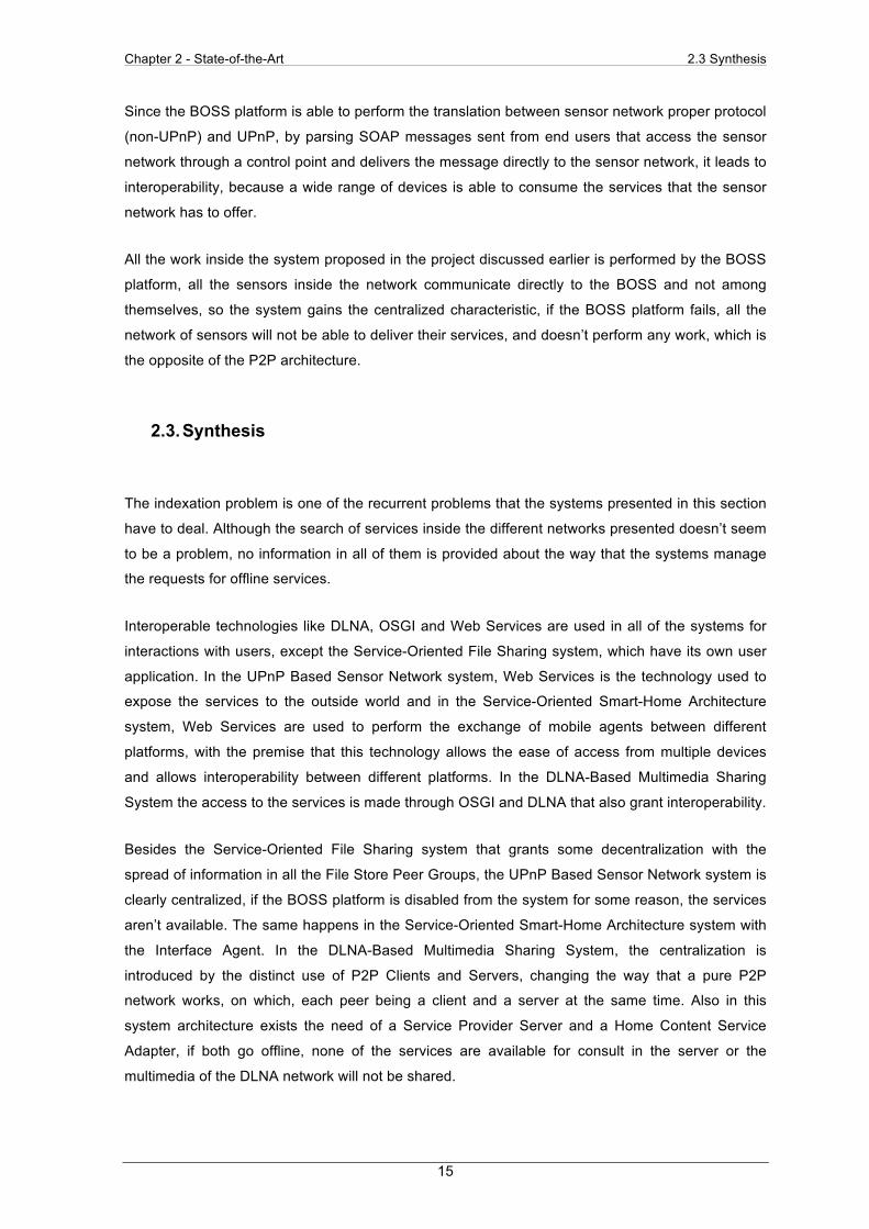
Since the BOSS platform is able to perform the translation between sensor network proper protocol
(non-UPnP) and UPnP, by parsing SOAP messages sent from end users that access the sensor
network through a control point and delivers the message directly to the sensor network, it leads to
interoperability, because a wide range of devices is able to consume the services that the sensor
network has to offer.
All the work inside the system proposed in the project discussed earlier is performed by the BOSS
platform, all the sensors inside the network communicate directly to the BOSS and not among
themselves, so the system gains the centralized characteristic, if the BOSS platform fails, all the
network of sensors will not be able to deliver their services, and doesn’t perform any work, which is
the opposite of the P2P architecture.
2.3. Synthesis
The indexation problem is one of the recurrent problems that the systems presented in this section
have to deal. Although the search of services inside the different networks presented doesn’t seem
to be a problem, no information in all of them is provided about the way that the systems manage
the requests for offline services.
Interoperable technologies like DLNA, OSGI and Web Services are used in all of the systems for
interactions with users, except the Service-Oriented File Sharing system, which have its own user
application. In the UPnP Based Sensor Network system, Web Services is the technology used to
expose the services to the outside world and in the Service-Oriented Smart-Home Architecture
system, Web Services are used to perform the exchange of mobile agents between different
platforms, with the premise that this technology allows the ease of access from multiple devices
and allows interoperability between different platforms. In the DLNA-Based Multimedia Sharing
System the access to the services is made through OSGI and DLNA that also grant interoperability.
Besides the Service-Oriented File Sharing system that grants some decentralization with the
spread of information in all the File Store Peer Groups, the UPnP Based Sensor Network system is
clearly centralized, if the BOSS platform is disabled from the system for some reason, the services
aren’t available. The same happens in the Service-Oriented Smart-Home Architecture system with
the Interface Agent. In the DLNA-Based Multimedia Sharing System, the centralization is
introduced by the distinct use of P2P Clients and Servers, changing the way that a pure P2P
network works, on which, each peer being a client and a server at the same time. Also in this
system architecture exists the need of a Service Provider Server and a Home Content Service
Adapter, if both go offline, none of the services are available for consult in the server or the
multimedia of the DLNA network will not be shared.

Chapter 2 - State-of-the-Art 2.4 Advancement
16
Translation is only addressed in the UPnP Based Sensor Network system, where it is mentioned
that the BOSS platform translates the requests between UPnP and non-UPnP devices. In the
Service-Oriented File Sharing system, there aren’t different technologies working together, since it
is provided with its own user application interface. In the case of the Service-Oriented Smart-Home
Architecture each OSGI platform has a Web Service bundle that automatically deploys the agents
to the other Web Services bundles. In the DLNA-Based Multimedia Sharing System since the client
trying to ask for a multimedia file, grabs it directly at the DLNA server inside the DLNA network, no
translation is executed except at the IP level.
In the Table 2.1, an overview that matches the systems studied with the characteristics of the
problem that is trying to be solved is presented.
Table 2.1 - Overview of the State of the Art Research
Indexation Exposition Translation
Service-Oriented File Sharing
Made by the FSPG, mobilization isn't granted for
the router peers
The system has its own user application Not required
UPnP-Based Sensor Network Management
Architecture
Made by the BOSS platform, problem with offline node
Boss exposes the services to the Control Point trough
SOAP Performed by the BOSS
Service-Oriented Smart-Home Architecture Based
on OSGI and Mobile-Agent Technology
Made by the Interface Agent, problem with the offline node
Each platform uses SOAP to export agents to other
platforms
Not required each platform has a Web
Services bundle
DLNA-Based Multimedia Sharing System for OSGI
Framework With Extension to P2P Network
Made by the access to the Service Provider Server
DLNA inside the home network and OSGI in the
outside P2P network Not required
2.4. Advancement
All the systems referred earlier aren’t able to solve all the characteristics of the problem discussed per
se. Different functionalities of each system were extracted from all of them, in order to create a unique
solution capable of fulfilling all the requirements already exposed.
From the systems studied the only one that grants decentralization, in which the information for the
files is kept by groups of peers with special abilities, is the Service-Oriented File Sharing system. So
this kind of approach is the one used on the P2P Service Exposers, since they are a group of peers
that still belong to the network, with the ability of knowing all the available services in the network.
The exposition of services in all the systems studied, except the case of the Service-Oriented File
Sharing system is done by using standard interoperable technologies based in Service Oriented

Chapter 2 - State-of-the-Art 2.4 Advancement
17
Architecture such as Web Services or OSGI. That characteristic grants that all kinds of users can
access the network, by different operating systems and using different devices. So the P2P Service
Exposer also uses this approach by introducing Web Services as the technology to gather the
client requests.
The only system that performs translation between technologies is the UPnP Based Sensor
Network system using the BOSS platform, so that capability was created to allow that the P2P
Service Exposer system performs the translation between P2P and Web Services.
In short, the decentralization functionality of the P2P Service Exposer was based in the Service-
Oriented File Sharing system, to expose the services it uses Web Services, because of its
interoperability features, and the translation between technologies is based on the way that the
UPnP Based Sensor Network built the BOSS platform.

Chapter 2 - State-of-the-Art 2.4 Advancement
18
Chapter 3 - P2P Service Exposer Architecture 3.1 Concept
19
Chapter 3 - P2P Service Exposer Architecture
3.1. Concept
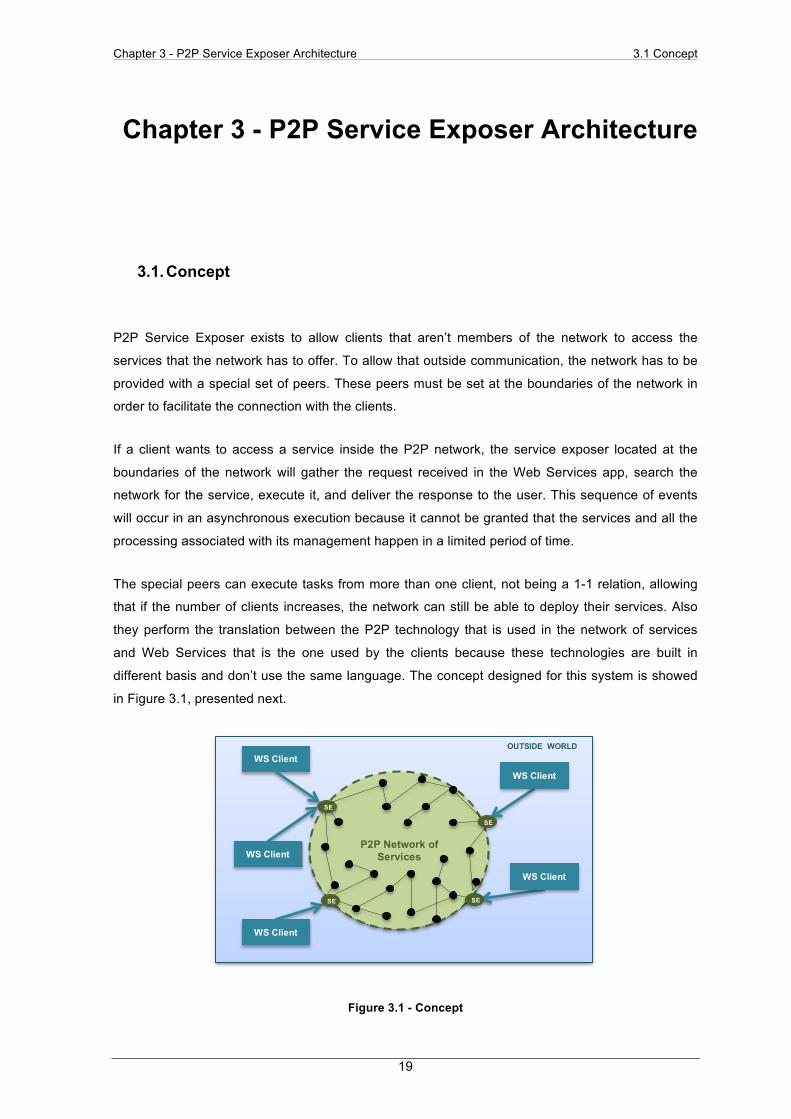
P2P Service Exposer exists to allow clients that aren’t members of the network to access the
services that the network has to offer. To allow that outside communication, the network has to be
provided with a special set of peers. These peers must be set at the boundaries of the network in
order to facilitate the connection with the clients.
If a client wants to access a service inside the P2P network, the service exposer located at the
boundaries of the network will gather the request received in the Web Services app, search the
network for the service, execute it, and deliver the response to the user. This sequence of events
will occur in an asynchronous execution because it cannot be granted that the services and all the
processing associated with its management happen in a limited period of time.
The special peers can execute tasks from more than one client, not being a 1-1 relation, allowing
that if the number of clients increases, the network can still be able to deploy their services. Also
they perform the translation between the P2P technology that is used in the network of services
and Web Services that is the one used by the clients because these technologies are built in
different basis and don’t use the same language. The concept designed for this system is showed
in Figure 3.1, presented next.
Figure 3.1 - Concept
OUTSIDE WORLD
P2P Network of Services
SE
WS Client
WS Client
WS Client
WS Client
WS Client
SE
SE
SE

Chapter 3 - P2P Service Exposer Architecture 3.2 Architecture Overview
20
3.2. Architecture Overview
The architecture for the P2P Service Exposer has the following characteristics:
• Indexation: The P2P Service Exposer has to know, at the moment, which services are
available in the network for being exposed, handling the mobility and disconnection of
peers.
• Exposition: The P2P Service Exposer has to publish the services to the outside world using
a technology such as Web Services.
• Translation: The P2P Service Exposer has to perform the translation between requests
from the outside and inside technologies, by doing a match between the different
languages used.
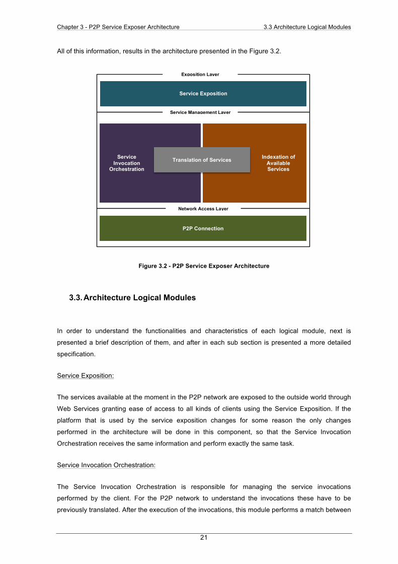
To meet these requirements the architecture designed, uses three different layers with five different
logical modules. A brief description of the functionality of each layer is presented next.
Exposition Layer
This is the top layer of the architecture that handles the client interactions. The Web Service
technology is the one used at this point and at this layer no information about how the network is
implemented is known. In its composition only the Service Exposition logical module exists.
Service Management Layer
This is the middle layer of the architecture that is responsible for managing the services and
services requests and performs the necessary translations. The Indexation of Available Services,
Service Invocation Orchestration and Translation of Services logical modules compose it.
Network Access Layer
This is the bottom layer of the architecture that actually connects the system to the P2P network. It
is only aware of the use of P2P technology and no information about the way the services are
exposed to the client is known. It is only composed by one logical module the P2P Connection.
Chapter 3 - P2P Service Exposer Architecture 3.3 Architecture Logical Modules
21
All of this information, results in the architecture presented in the Figure 3.2.
Figure 3.2 - P2P Service Exposer Architecture
3.3. Architecture Logical Modules
In order to understand the functionalities and characteristics of each logical module, next is
presented a brief description of them, and after in each sub section is presented a more detailed
specification.
Service Exposition:
The services available at the moment in the P2P network are exposed to the outside world through
Web Services granting ease of access to all kinds of clients using the Service Exposition. If the
platform that is used by the service exposition changes for some reason the only changes
performed in the architecture will be done in this component, so that the Service Invocation
Orchestration receives the same information and perform exactly the same task.
Service Invocation Orchestration:
The Service Invocation Orchestration is responsible for managing the service invocations
performed by the client. For the P2P network to understand the invocations these have to be
previously translated. After the execution of the invocations, this module performs a match between
Service Invocation
Orchestration
Indexation of Available Services
Service Exposition
P2P Connection
Translation of Services
Exposition Layer
Service Management Layer
Network Access Layer
Chapter 3 - P2P Service Exposer Architecture 3.3 Architecture Logical Modules
22
invocation-response so that the client obtains the correct response and translation of the response
to client language is performed.
Translation of Services:
According to the language that the Service Exposition uses to communicate with the outside, the
Translation of Services is responsible for performing the translation between it and the language
that is used inside the network of services. It is able to perform different translations since the
services can be exposed in different platforms, and the network of services can be implemented
using different technologies.
Indexation of Available Services:
The Indexation of Available Services is responsible for knowing all the services available in the
network, know if they are available at the moment, since they can be offline, and where they are
located inside the P2P network. When the information about the services and respective locations
are gathered, a translation of it has to be done so that the information can be passed to the Service
Exposer and therefore to the outside world.
P2P Connection:
The P2P Connection is responsible for performing the bounding to the P2P network of services. If
the network changes, or the services provided by it changes, the only changes performed in the
architecture will be done in this block.
To represent the interfaces of each logical module, the following notation will be used in the next
subsections:
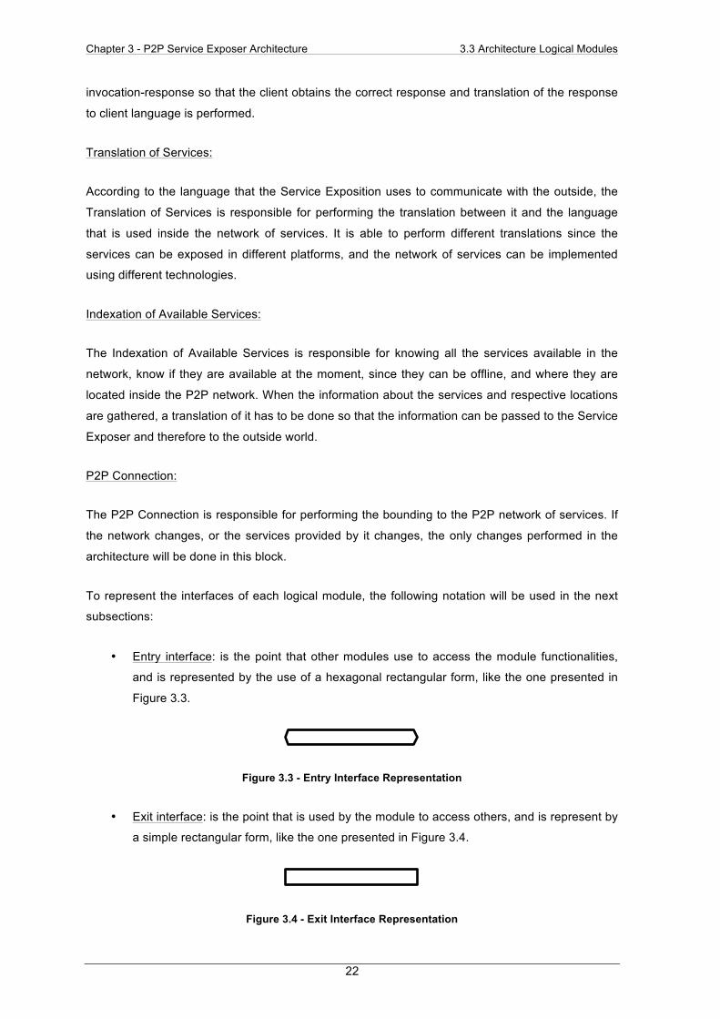
• Entry interface: is the point that other modules use to access the module functionalities,
and is represented by the use of a hexagonal rectangular form, like the one presented in
Figure 3.3.
Figure 3.3 - Entry Interface Representation
• Exit interface: is the point that is used by the module to access others, and is represent by
a simple rectangular form, like the one presented in Figure 3.4.
Figure 3.4 - Exit Interface Representation

Chapter 3 - P2P Service Exposer Architecture 3.3 Architecture Logical Modules
23
Each logical module entry interface, have associated methods that are presented using the formal
specification language VDM++ (Durr and van Katwijk 1992). The following definitions are common
to multiple methods, so are presented next:
• The Service interface is used to define the service type and is composed by the description
of the service, in which the service details are specified and the methods exposed by the
service:
public interface Service
public serviceDescription: Object;
public serviceMethods: Object;
end Service
• The ResponseHandler interface is used to perform callbacks to the methods that need
asynchronous responses to perform all their tasks. It implements one method that handles
the Response object.
public interface ResponseHandler public responseReceived(Response: Object);
end ResponseHandler
• The InvokedMethod interface is used to invoke the services methods. It is composed by
the service methods, arguments, the invoked service and a callback to the invocation.
public interface InvokedMethod
public method: Object;
public args: Object;
public service: Object;
public responseCallback: ResponseHandler;
end InvokedMethod
3.3.1. Service Exposition
The Service Exposition logical module is responsible for providing the connection of the system
with the outside client, exposing the available services in the P2P network through a Web Service
platform. If this platform changes for some reason the only changes performed in the architecture
will be done in this component.

Chapter 3 - P2P Service Exposer Architecture 3.3 Architecture Logical Modules
24
The Figure 3.5 shows this module composition.
Figure 3.5 - Service Exposition logical module
Each entry interface performs the following tasks:
The Exposition API is built as the client interface of the system, since it gathers the client requests
and retrieves their responses. This interface implements Web Service methods dependant of the
technology used, so none are presented.
The Publish API is used to receive the available services in the network so that after they can be
published to the client. This interface implements the methods:
• public publishService(newService:Service) - method that receives the service to
publish in the Exposition interface, if the service suffer alterations this method is also
called, to update the service definition;
• public removeService(serviceToRemove:Service) - method that receive the service that
is no longer available, to remove it from the Exposition interface;
The exit interface performs the following tasks:
The Invocation API is used to pass the requests for services that the client makes, to the module
that prepares them to reach the P2P network
The workload of this logical module starts at the Deploy API because if no services are available
then nothing is exposed to the client. When a new service or the information that a service is offline
arrives at this module, the Exposition API takes action and provides the client the changes
occurred.
If the client has a request to a service, the module passes it from the Exposition to the Invocation
API, so that the service can reach the network and be executed. The service response takes the
opposite direction since it arrives to the module by the Invocation API and leaves the block by the
Exposition API and provides the result back to the client.
Service Exposition Invocation API
Exposition API
Publish API

Chapter 3 - P2P Service Exposer Architecture 3.3 Architecture Logical Modules
25
3.3.2. Service Invocation Orchestration
The Service Invocation Orchestration logical module is responsible for managing the service
invocations performed by the client. Before the P2P network can execute these invocations they
have to be passed for translations to the module that performs it, that is also one of the tasks of this
module. After the execution of the invocations in the network, this module performs a match
between invocation-response so that the client obtains the correct response and the translation of
the response to client language is performed.
The module and all its interfaces are showed in Figure 3.6.
Figure 3.6 - Service Invocation Orchestration module
The entry interface performs the following tasks:
The Invocation API is used by other modules in the architecture to pass invocations for the services
available to the network of services. This interface implements the following method:
• public invokedService(invokeWS: InvokedMethod) - method that receives the
invocation for a service method in Web Services language.
Each exit interface performs the following tasks:
The Translation API is used by this module to translate the requests between the technologies
used at both ends of the system.
The Service API is used by this module to pass the translated requests for services, to the module
that will connect to the network.
This module starts its work through the Invocation API, because if there aren’t any requests for
services, then it is permanently at an idle state. When an invocation arrives, it comes with the
outside technology language. So in order to be understood by the network, this module pass the
service to another one able to translate it through the Translation API and uses this same interface
to grab the translated service.
Service Invocation Orchestration Invocation API
Service API Translation API
Chapter 3 - P2P Service Exposer Architecture 3.3 Architecture Logical Modules
26
After being translated the service is passed to another module that will perform the arrangements
for the service to be executed through the Service API. When a response is generated happens, it
has to be passed to the client, since it is waiting for it. So the Translation API is used again to
perform the translation to the language that the client understands. At last the Invocation API takes
action to deliver the service feedback already translated to the client.
If the client performs multiple invocations, this module can’t afford to be in an idle state and perform
no other action until the first gets executed, so to enhance its performance this module keeps
knowledge about the invocations that pass through it, so that when a result of a translation or a
result of an invocation arrives, it matches them with the invocation, and the client receives the
correct response, working asynchronously.
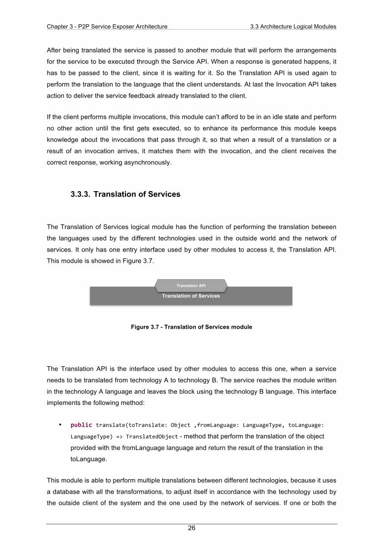
3.3.3. Translation of Services
The Translation of Services logical module has the function of performing the translation between
the languages used by the different technologies used in the outside world and the network of
services. It only has one entry interface used by other modules to access it, the Translation API.
This module is showed in Figure 3.7.
Figure 3.7 - Translation of Services module
The Translation API is the interface used by other modules to access this one, when a service
needs to be translated from technology A to technology B. The service reaches the module written
in the technology A language and leaves the block using the technology B language. This interface
implements the following method:
• public translate(toTranslate: Object ,fromLanguage: LanguageType, toLanguage:
LanguageType) => TranslatedObject - method that perform the translation of the object
provided with the fromLanguage language and return the result of the translation in the
toLanguage.
This module is able to perform multiple translations between different technologies, because it uses
a database with all the transformations, to adjust itself in accordance with the technology used by
the outside client of the system and the one used by the network of services. If one or both the
Translation of Services Translation API

Chapter 3 - P2P Service Exposer Architecture 3.3 Architecture Logical Modules
27
technologies changes at any moment, no modifications have to be performed in the system, this
module still performs the translations, just by expanding its capacity, including the new
transformations in the database.
3.3.4. Indexation of Available Services
The Indexation of Available Services is the control point of the architecture being responsible of
knowing all the services available in the network, manage their status, and their location inside the
P2P network of services. After that, it builds a list of services and respective locations perform the
translation of it to the outside language so that the services could reach the client. The module
composition is showed in Figure 3.8.
Figure 3.8 - Indexation of Available Services module
Each interface performs the following tasks:
The Publish API is used to expose the available services of the network to the module that handles
the communication with the client.
The Discovery API is the interface used by this module to know all the available services on the
P2P network.
The Translation API is used to translate the services between outside technology language and
network technology language.
This module uses the Discovery API to find the list of available services and their locations inside
the network. When this list arrives at this interface, it comes in the form of the network language, so
the Translation API takes action to perform the translation from network technology language to
outside client technology language. After waiting for the result of the translation of the list of
services, the Deploy API interface is used by this module to pass the list to the one that binds to
the client.
Indexation of Available Services
Publish API
Discovery API Translation API

Chapter 3 - P2P Service Exposer Architecture 3.3 Architecture Logical Modules
28
The major importance of this module focuses on the fact that it has to be always available to
perform its tasks, this is the control point of the architecture because it has to be aware of the state
of the services all the time, monitoring continuously the network, to discover the availability of new
services, the unavailability of old services and if a service change its location and therefore
manage this information to the client. If any of these tasks fail, then the client won’t receive the
actual information of the network, and the system is failing to expose their services.
3.3.5. P2P Connection
The P2P Connection is responsible for performing the connection to the P2P network of services. If
the network or the services that it provides change, the architecture will suffer alterations in this
module. The module composition showed in Figure 3.9.
Figure 3.9 - P2P Connection module
Each entry interface performs the following tasks:
The Service API is used by other modules to pass the request for a service to the network of
services and is used by the P2P Connection to provide the result of this execution back. The
interface implements the following methods
• public invokeP2PService(invokeP2P: InvokedMethod) - method that receives the
service invoked in P2P language.
The Discovery API permits the search for services and provides the information of the available
services at the moment in the network.
• public getallServices() => result listofServices - method used to retrieve the list of
the available services in the P2P network
P2P Connection Connection API
Service API Discovery API

Chapter 3 - P2P Service Exposer Architecture 3.4 Architecture Composition
29
The exit interface performs the following tasks:
The Connection API is responsible for making the bound between this module and the network of
Services, allowing various network configurations and technologies, and its dependent of the P2P
technology.
The first interaction with this module comes from the Discovery API, since it uses it to reach the
network of services. The Connection API is used in to perform the connection to the network, to
search the services and return the result of the available ones to the Discovery API, in order to
pass the other modules and reach the client.
After knowing the available services the client can perform a request that reaches this module
through the Service API, and is passed to the Connection API to be executed in the network. When
the response of the service is generated, it reaches this module through the Connection API and is
passed back to the Service API to be exported to other modules in order to reach the client.
3.4. Architecture Composition
All together the logical modules described in the previous section with their interfaces provide a
new approach of representing the P2P Service Exposer Architecture, as showed in Figure 3.10.
Figure 3.10 - Architecture Composition
Service Invocation
Orchestration
Translation of Services
Service Management Layer
Network Access Layer
Service Exposition Invocation API
Exposition API
Publish API
P2P Connection
Connection API
Service API Discovery API
Service API
Translation API
Translation API
Invocation API
Indexation of Available
Services
Translation API
Discovery API
Publish API
Exposition Layer

Chapter 3 - P2P Service Exposer Architecture 3.5 Architecture Module Sequence
30
3.5. Architecture Module Sequence
Although each logical module performs its own tasks, if they work solo the P2P Service Exposer
wouldn’t meet the requirements proposed in the beginning of this section. Two sequence diagrams
representing the connections that occur inside the architecture between logical modules are
presented next. They are defined according to the UML format (IBM 2004), in which, each module
is represented by a lifeline block. Each action is represented by a closed end arrow, if it is
synchronous, and by an open-end arrow in the asynchronous case. These diagrams explain the
following two actions.
• Indexation of Services: Showing the actions that occur in order to provide the available
services to the client.
• Invoke Service: Showing all the actions resultant of an invocation for a service performed
by a client.
3.5.1. Indexation of Services
Using the architecture with the layers, logical modules and interfaces proposed earlier, the flow of
work starts at the Indexation of Available Services. To know the available services it asks the P2P
Connection module to get all the services in the network. To do so the P2P Connection has to
perform a real connection to the P2P network to gather them.
When the list of services is provided to the Indexation of Available Services, then some processing
of this list has to be performed in order of finding which services are new in the list, and which
services are not available anymore.
• For each new service, a new translation is performed, since they arrive at the Indexation of
Available Services module using the P2P network language format, so the service is
passed to the Translation of Services. After translated it can be exposed to the outside
world, so the Indexation of Available Services passes each new service to the Service
Exposer.
• For each offline service, the Indexation of Available Services only has to remove it from the
Service Exposer, so that the client can’t perform requests for it.
• For each service that changed its location inside the network, a new translation is also
performed, since they arrive at the Indexation of Available Services in the P2P network
language format, so the service is passed to the Translation of Services module. After
translated it can be exposed to the outside world, they’re passed to the Service Exposer.
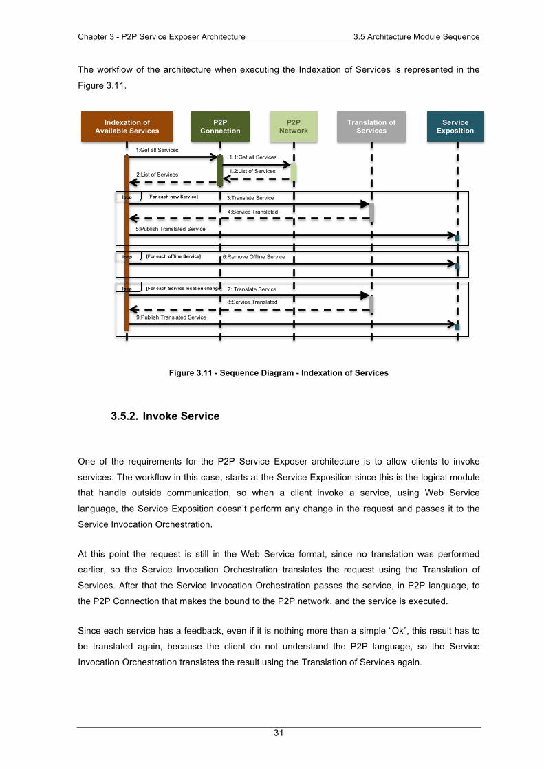
Chapter 3 - P2P Service Exposer Architecture 3.5 Architecture Module Sequence
31
The workflow of the architecture when executing the Indexation of Services is represented in the
Figure 3.11.
Figure 3.11 - Sequence Diagram - Indexation of Services
3.5.2. Invoke Service
One of the requirements for the P2P Service Exposer architecture is to allow clients to invoke
services. The workflow in this case, starts at the Service Exposition since this is the logical module
that handle outside communication, so when a client invoke a service, using Web Service
language, the Service Exposition doesn’t perform any change in the request and passes it to the
Service Invocation Orchestration.
At this point the request is still in the Web Service format, since no translation was performed
earlier, so the Service Invocation Orchestration translates the request using the Translation of
Services. After that the Service Invocation Orchestration passes the service, in P2P language, to
the P2P Connection that makes the bound to the P2P network, and the service is executed.
Since each service has a feedback, even if it is nothing more than a simple “Ok”, this result has to
be translated again, because the client do not understand the P2P language, so the Service
Invocation Orchestration translates the result using the Translation of Services again.
Indexation of Available Services
P2P Connection
P2P Network
Translation of Services
Service Exposition
1:Get all Services 1.1:Get all Services 1.2:List of Services
3:Translate Service 4:Service Translated
5:Publish Translated Service
6:Remove Offline Service
7: Translate Service 8:Service Translated
9:Publish Translated Service
[For each new Service]
[For each offline Service]
[For each Service location change]
loop
loop
loop
2:List of Services
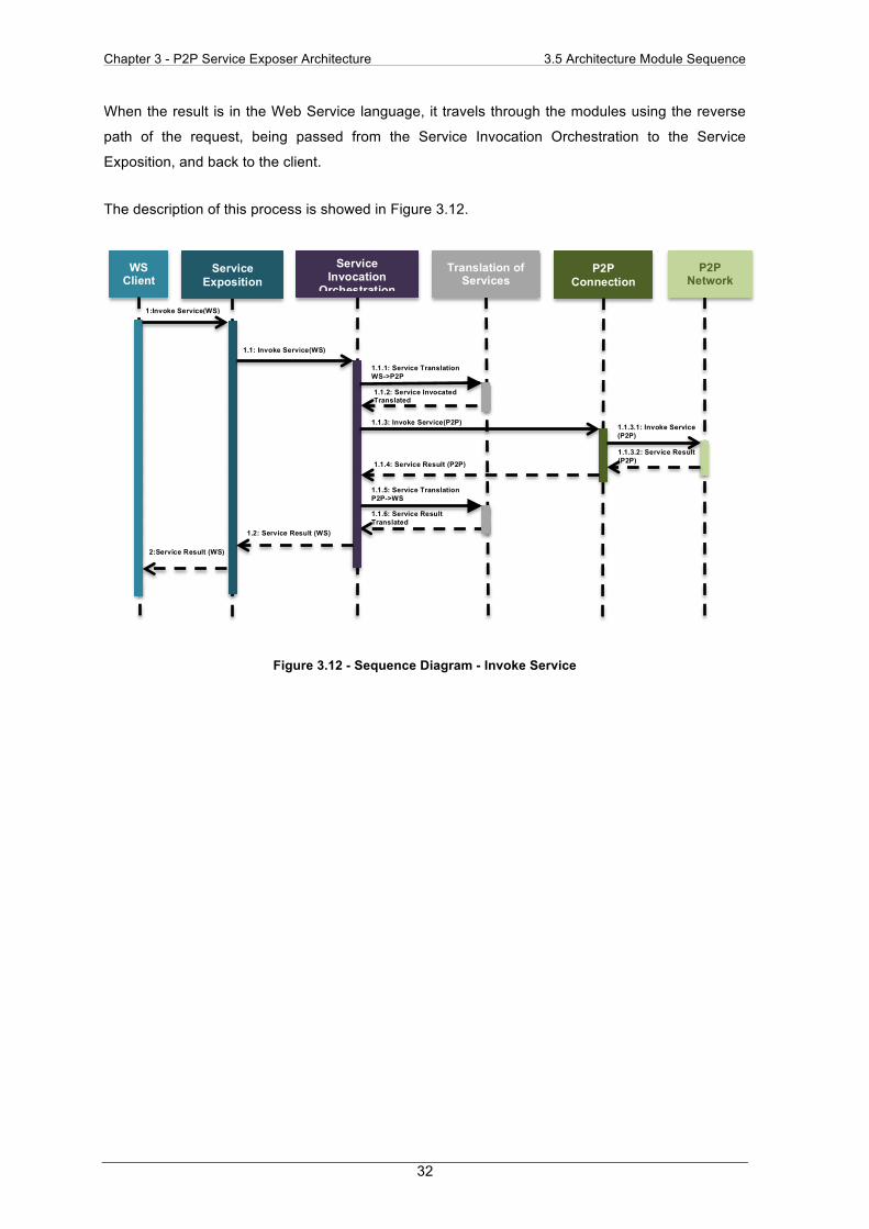
Chapter 3 - P2P Service Exposer Architecture 3.5 Architecture Module Sequence
32
When the result is in the Web Service language, it travels through the modules using the reverse
path of the request, being passed from the Service Invocation Orchestration to the Service
Exposition, and back to the client.
The description of this process is showed in Figure 3.12.
Figure 3.12 - Sequence Diagram - Invoke Service
WS Client
P2P Connection
P2P Network
Translation of Services
Service Exposition
1.1: Invoke Service(WS)
Service Invocation
Orchestration
1:Invoke Service(WS)
1.1.1: Service Translation WS->P2P 1.1.2: Service Invocated Translated
1.1.3: Invoke Service(P2P) 1.1.3.1: Invoke Service (P2P) 1.1.3.2: Service Result (P2P) 1.1.4: Service Result (P2P)
1.1.5: Service Translation P2P->WS 1.1.6: Service Result Translated
1.2: Service Result (WS) 2:Service Result (WS)
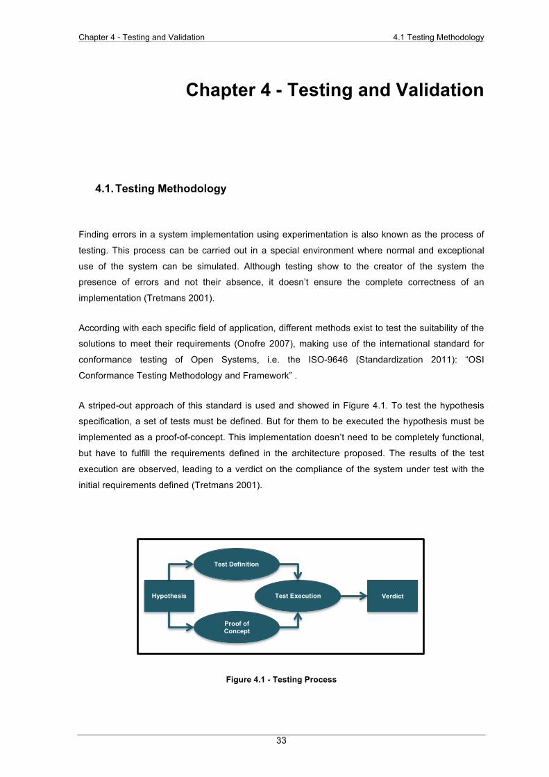
Chapter 4 - Testing and Validation 4.1 Testing Methodology
33
Chapter 4 - Testing and Validation
4.1. Testing Methodology
Finding errors in a system implementation using experimentation is also known as the process of
testing. This process can be carried out in a special environment where normal and exceptional
use of the system can be simulated. Although testing show to the creator of the system the
presence of errors and not their absence, it doesn’t ensure the complete correctness of an
implementation (Tretmans 2001).
According with each specific field of application, different methods exist to test the suitability of the
solutions to meet their requirements (Onofre 2007), making use of the international standard for
conformance testing of Open Systems, i.e. the ISO-9646 (Standardization 2011): “OSI
Conformance Testing Methodology and Framework” .
A striped-out approach of this standard is used and showed in Figure 4.1. To test the hypothesis
specification, a set of tests must be defined. But for them to be executed the hypothesis must be
implemented as a proof-of-concept. This implementation doesn’t need to be completely functional,
but have to fulfill the requirements defined in the architecture proposed. The results of the test
execution are observed, leading to a verdict on the compliance of the system under test with the
initial requirements defined (Tretmans 2001).
Figure 4.1 - Testing Process
Hypothesis
Test Definition
Proof of Concept
Implementatio
Test Execution Verdict
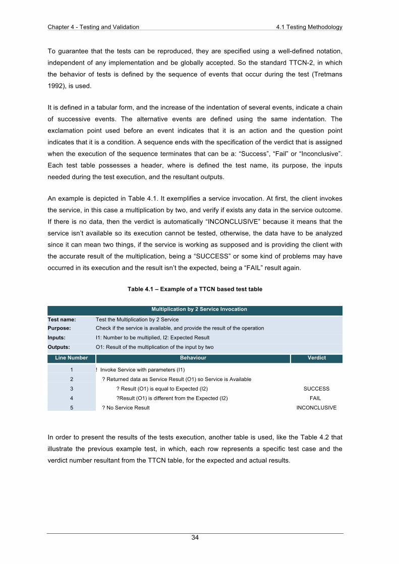
Chapter 4 - Testing and Validation 4.1 Testing Methodology
34
To guarantee that the tests can be reproduced, they are specified using a well-defined notation,
independent of any implementation and be globally accepted. So the standard TTCN-2, in which
the behavior of tests is defined by the sequence of events that occur during the test (Tretmans
1992), is used.
It is defined in a tabular form, and the increase of the indentation of several events, indicate a chain
of successive events. The alternative events are defined using the same indentation. The
exclamation point used before an event indicates that it is an action and the question point
indicates that it is a condition. A sequence ends with the specification of the verdict that is assigned
when the execution of the sequence terminates that can be a: “Success”, “Fail” or “Inconclusive”.
Each test table possesses a header, where is defined the test name, its purpose, the inputs
needed during the test execution, and the resultant outputs.
An example is depicted in Table 4.1. It exemplifies a service invocation. At first, the client invokes
the service, in this case a multiplication by two, and verify if exists any data in the service outcome.
If there is no data, then the verdict is automatically “INCONCLUSIVE” because it means that the
service isn’t available so its execution cannot be tested, otherwise, the data have to be analyzed
since it can mean two things, if the service is working as supposed and is providing the client with
the accurate result of the multiplication, being a “SUCCESS” or some kind of problems may have
occurred in its execution and the result isn’t the expected, being a “FAIL” result again.
Table 4.1 – Example of a TTCN based test table
Multiplication by 2 Service Invocation
Test name: Test the Multiplication by 2 Service Purpose: Check if the service is available, and provide the result of the operation
Inputs: I1: Number to be multiplied, I2: Expected Result
Outputs: O1: Result of the multiplication of the input by two
Line Number Behaviour Verdict
1 ! Invoke Service with parameters (I1) 2 ? Returned data as Service Result (O1) so Service is Available 3 ? Result (O1) is equal to Expected (I2) SUCCESS
4 ?Result (O1) is different from the Expected (I2) FAIL
5 ? No Service Result INCONCLUSIVE
In order to present the results of the tests execution, another table is used, like the Table 4.2 that
illustrate the previous example test, in which, each row represents a specific test case and the
verdict number resultant from the TTCN table, for the expected and actual results.

Chapter 4 - Testing and Validation 4.2 Proof of Concept Implementation
35
Table 4.2 - Test Case Example
Test
Input Output Result (Line number)
I1: Number I2:Expected Result O1: Result Expected Actual
1 60 120 120 (3) (3)
2 8 16 120 (3) (4)
3 0 0 No Data (3) (5)
4.2. Proof of Concept Implementation
The P2P Service Exposer architecture is the middle point between two different technologies, P2P
and Web Services. But since this is a generic approach that can be applied to multiple
implementations, two of them are chosen. So, for each one of the technologies, the following
implementations will be used:
• P2P Network: The network used to test this architecture is based on a JXTA P2P protocol
specification, which implementation was developed in the European research project
CuteLoop FP7-ICT-216420
• Web Services: For handling the implementation of the SOAP protocol is the chosen among
all the others, since this is a widely used standard and the web server platform used is
Apache Axis2/Java.
The P2P network used in this proof of concept is the one implemented in the European research
project CuteLoop FP7-ICT-216420 based in the JXTA specification. The Juxtapose (JXTA) is an
open source P2P protocol specification, in which the protocols are defined as a set of XML
messages that allow for any device connected to a network, to exchange messages and
collaborate independently of the underlying network topology. JXTA also helps to solve problems
related with the use of firewalls, because it creates a virtual overlay network. Also JXTA uses
pipes, which abstract the transport layer for end-to-end communication between different peers in
the network.
The enhancements implemented in the project referred, at the JXTA implementation, are the
following:

Chapter 4 - Testing and Validation 4.3 Test Definition and Execution
36
• Mobility of Users: The way that the advertisements are done inside the network was
changed to allow mobile devices, like the ones used inside home networks.
• Complexity Reduction: The Usage APIs were redesigned to reduce the complexity of the
solution, so that the number of users could increase.
• Services Exposition: An architecture was created to permit that Java classes could be
exposed like services, without being needed the JXTA configuration overhead.
For the Web Services, the Apache Axis2/Java is the chosen platform along with the SOAP
protocol. The Simple Object Access Protocol (SOAP) is also a protocol specification, used for
exchanging structured information. It also relies on XML for its message format and in Application
Layer protocols, such as Hyper Transfer Protocol (HTTP) or Simple Mail Transfer Protocol (SMTP).
The Apache Axis2 is a core engine for Web Services, since it not only provide the capability to add
Web Services interfaces to Web applications but also can function as a standalone server
application. It can work with multiple implementations for Web Services, such as SOAP or REST
and also either synchronous or asynchronous implementations can be used.
The asynchronous implementation is the chosen one, in which it is used a client programing model
based in one-way transport, so that the outgoing and incoming messages use two engines and the
outgoing transport don’t wait for a response. Instead the incoming message is processed by a
different transport that is created by a call object while it is sending the request.
Since this two chosen technologies use the JAVA language because this is a general purposed,
concurrent and class-based, object oriented language that is designed to permit the fewest
dependencies as possible, being the generated code runnable in multiple platforms, without
recompilation, this is also the choice used in the P2P Service Exposer.
4.3. Test Definition and Execution
Following the method described earlier, the test cases will be divided in two groups, with each one
corresponding to a different requirement:
• Invocation of Services: In this case it is tested if the system can handle the client requests
for a service that is available. Primarily it is checked if the service is available, and after, if
the service provide a result equal to the expected.
• Indexation of Services: In this case it is tested if the system can handle the service
management, reacting as expected according to different actions provided in the service. It
is also primarily checked if the service is available, before performing any action.

Chapter 4 - Testing and Validation 4.3 Test Definition and Execution
37
A more detailed definition of each test is presented in the next sections.
4.3.1. Invocation of Services
Test Definition
This test is performed to grant that the system can actually deploy services to outside clients, which
is a main characteristic of the system. It is checked the service availability and if the result of the
service execution is a valid. It is implicit in this test that the translation of the service is a success,
or else the service execution wouldn’t be valid.
To perform the test, the service, the according service method and the expected result, are the
inputs, and the action taken is the invocation of the service with the provided method. If the
invocation returns any output, it proves that the service is available as it was expected. So after it is
necessary to verify if the output is accurate according to the service requested, comparing the
output with the expected result.
The system can fail in two conditions, if the service doesn’t provide any result with its execution or
if it does, the result isn’t the expected value. As referred earlier a TTCN based table is presented in
Table 4.3 to demonstrate the test definition.
Table 4.3 - Invocation of Services: Test Definition
Invocation of Services
Test name: Invoke Service Purpose: Check Service Availability and Service Result
Inputs: I1: Service; I2: Method; I3: Expected Result
Outputs: O1: Service Result
Line Number Behaviour Verdict
1 ! Invoke Service (I1) using Method (I2) 2 ? Returned Service Result (O1) so Service is Available 3 ! Compare Service Result (O1) with Expected Result (I2) 4 ? Same Result SUCCESS
5 ? Different Results FAIL
6 ? No Results Returned FAIL
Text Execution
More than one test with different inputs is executed using the previous definitions to verify the
consistency of the results. To perform all the tests registered in Table 4.4, the system has been
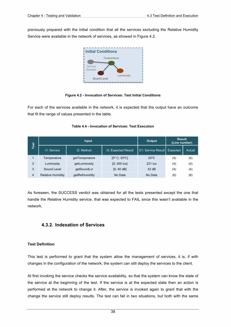
Chapter 4 - Testing and Validation 4.3 Test Definition and Execution
38
previously prepared with the initial condition that all the services excluding the Relative Humidity
Service were available in the network of services, as showed in Figure 4.2.
Figure 4.2 - Invocation of Services: Test Initial Conditions
For each of the services available in the network, it is expected that the output have an outcome
that fit the range of values presented in the table.
Table 4.4 - Invocation of Services: Test Execution
Test
Input Output Result (Line number)
I1: Service I2: Method I3: Expected Result O1: Service Result Expected Actual
1 Temperature getTemperature [0º C; 30ºC] 22ºC (4) (4)
2 Luminosity getLuminosity [0; 300 lux] 221 lux (4) (4)
3 Sound Level getSoundLvl [0; 40 dB] 33 dB (4) (4)
4 Relative Humidity getRelHumidity No Data No Data (6) (6)
As foreseen, the SUCCESS verdict was obtained for all the tests presented except the one that
handle the Relative Humidity service, that was expected to FAIL since this wasn’t available in the
network.
4.3.2. Indexation of Services
Test Definition
This test is performed to grant that the system allow the management of services, it is, if with
changes in the configuration of the network, the system can still deploy the services to the client.
At first invoking the service checks the service availability, so that the system can know the state of
the service at the beginning of the test. If the service is at the expected state then an action is
performed at the network to change it. After, the service is invoked again to grant that with the
change the service still deploy results. The test can fail in two situations, but both with the same
Initial Conditions
Temperature
Luminosity Sound Level
Service Exposer

Chapter 4 - Testing and Validation 4.3 Test Definition and Execution
39
condition, that is the service isn’t at the state that is expected, before or after the changes applied
to it. Again a TTCN based table, Table 4.5, showing the test definition is showed next.
Table 4.5 - Indexation of Services: Test Definition
Indexation of Services Test name: Indexation of Services Purpose: Check the Indexation of Services according to events Inputs: I1: Service; I2: Event; I3: Expected Result before Event; I4: Expected Result after Event; Outputs: O1: Service Result before Event; O2: Service Result after Event;
Line Number Behaviour Verdict 1 ! Invoke Service (I1)
2 ? Service Result (O1) equal to Expected Result1 (I3) 3 ! Do Event (I2) 4 ! Invoke Service (I1) 5 ? Service Result (O2) equal to Expected Result2 (I4) SUCCESS
6 ? Service Result (O2) different from Expected Result2 (I4) FAIL 7 ? Result different form Expected Result1 (I3) FAIL
Test Execution
Once again, more than one test with different inputs is executed using the previous definitions to
verify the consistency of the results. To perform the tests registered in Table 4.6, the system has
been previously prepared with several initial conditions for each test id. Inputs and expected results
as showed next.
• Test 1: In this case the Temperature service doesn’t exist in the P2P network, so the event
is to expose the service. It is expected that the output for the invocation of the Temperature
service, O1, return no data, and after the execution of the event it returns a value at the
range of the expected result I3. For the network, it’s expected that the changes presented
in Figure 4.3 occur.
Figure 4.3 - Create Service Test
• Test 2: In this case the Sound Level service is available in the P2P network, so the event is
to disable the service. It is expected that the output for the invocation of the Sound Level
Initial Conditions After Event Execution
Temperature Service
Service Exposer
Service Exposer

Chapter 4 - Testing and Validation 4.3 Test Definition and Execution
40
service return a value in the acceptable range and after the event no data to be returned.
As for the network the changes presented in Figure 4.4 are expected.
Figure 4.4 - Disable Service Test
• Test 3: In this case the Luminosity service isn’t available in the network, but still it’s tried to
disable the service. In the two previous tests it is tested the change of state, so this test is
done to prove that the system really react to the command of the event even if it doesn’t
change the state of the service. It is expected that both outputs for the invocation of the
Luminosity don’t provide any data. Since that in this case no changes are performed in the
network, the figure before and after event will be the same, as showed in Figure 4.5.
Figure 4.5 - Maintain Service
• Test 4: In this case all the services are available in the network, and the event tested is the
change of the location of services. It is analysed that after changing its location inside the
network, the service still provide results. The changes in the network are displayed in
Figure 4.6, in which the peers have an associated logical location, represented by a letter.
Figure 4.6 - Change Service Location Test
Initial Conditions After Event Execution
Sound Level Service
Service Exposer
Service Exposer
Initial Conditions After Event Execution
Service Exposer
Service Exposer
A
Initial Conditions After Event Execution
Relative Humidity
C D
E B
B C
E
D
Relative Humidity
A A Z Z Service Exposer
Service Exposer
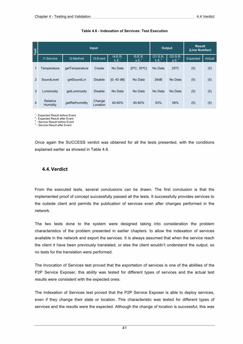
Chapter 4 - Testing and Validation 4.4 Verdict
41
Table 4.6 - Indexation of Services: Test Execution Te
st Input Output Result
(Line Number)
I1:Service I2:Method I3:Event I4:E.R. b.E.1
I5:E.R. a.E.2
O1:S.R.b.E.3
O2:S.R.a.E.4 Expected Actual
1 Temperature getTemperature Create No Data [0ºC; 30ºC] No Data 25ºC (5) (5)
2 SoundLevel getSoundLvl Disable [0; 40 dB] No Data 26dB No Data (5) (5)
3 Luminosity getLuminosity Disable No Data No Data No Data No Data (5) (5)
4 Relative Humidity getRelHumidity Change
Location 40-60% 40-60% 53% 58% (5) (5)
1 - Expected Result before Event 2 - Expected Result after Event 3 - Service Result before Event 4 - Service Result after Event
Once again the SUCCESS verdict was obtained for all the tests presented, with the conditions
explained earlier as showed in Table 4.6.
4.4. Verdict
From the executed tests, several conclusions can be drawn. The first conclusion is that the
implemented proof of concept successfully passed all the tests. It successfully provides services to
the outside client and permits the publication of services even after changes performed in the
network.
The two tests done to the system were designed taking into consideration the problem
characteristics of the problem presented in earlier chapters: to allow the indexation of services
available in the network and export the services. It is always assumed that when the service reach
the client it have been previously translated, or else the client wouldn’t understand the output, so
no tests for the translation were performed.
The Invocation of Services test proved that the exportation of services is one of the abilities of the
P2P Service Exposer, this ability was tested for different types of services and the actual test
results were consistent with the expected ones.
The Indexation of Services test proved that the P2P Service Exposer is able to deploy services,
even if they change their state or location. This characteristic was tested for different types of
services and the results were the expected. Although the change of location is successful, this was

Chapter 4 - Testing and Validation 4.4 Verdict
42
only possible taking in concern the way that the P2P network used to do the test was designed,
because it isn’t important for the network the real path to the service, but for other network
topologies this could be a flaw point.
So with the set of tests defined and executed, it can be concluded that the hypothesis formulated in
earlier chapters is a valid hypothesis, and that the created architecture is capable of handling all
the problem characteristics.
Chapter 5 - Conclusions and Future Work 5.1 Conclusions
43
Chapter 5 - Conclusions and Future Work
5.1. Conclusions
Smart homes are no longer predictions of the future presented in sci-fi movies. They started to be
built to provide us with comfort, and with the accelerated growth of technology we’ve become fully
dependent of their resources in our daily life. When all our devices started to communicate among
themselves, and with our houses, the home networks have become empowered. One of the
possible technologies to be used inside the home is P2P networks, since devices with poor
processing capabilities can share resources inside the network with other small devices or with
most capable computers. Also decentralization is granted with this architecture because there’s no
need for a central server.
The clients of the services that the home networks have to offer, are typically smartphones devices
who don’t want to belong to the network, they want to join other networks, be offline when they
want and surely they don’t want to share their resources with the P2P network, they want to use a
lite technology to access them. So the networks have to expose the services to their clients, using
peers that can be accessed from the outside and that perform translation between both
technologies, but how to create exposer peers?
These exposer peers have to provide the services available in the network at each moment, set at
the boundaries of the network. They can’t compromise the decentralization of the network, one of
the important qualities of a P2P network. They must allow multiple requests from the clients and by
different clients at the same time. Finally they have to perform translations between the languages
used between the P2P and the client technology.
A state-of-the-art research was performed to discover similar work done related with the problem
presented. It were selected different systems to be studied that handle the problem characteristics
as follow:
• In the Service-Oriented File Sharing system, the information of services is maintained by a
special set of peers called File Store Peer Groups, and fixed router peers do the routing of
requests between different VOs. In the other three systems exists centralization, since all
of them make use of a single platform to reach the information for the services.
Chapter 5 - Conclusions and Future Work 5.1 Conclusions
44
• To handle the different kinds of information trades, both UPnP-Based Sensor Network
Management Architecture and Service-Oriented Smart Home Architecture Based on OSGI
and Mobile-Agent Technology use the Web Service standard SOAP. The DLNA-Based
Multimedia Sharing System for OSGI Framework with Extension to P2P Network uses
DLNA inside the home network and OSGI in the outside P2P network. To access the
services and the Service-Oriented File Sharing use its own app.
• No translation is performed in any of the systems except the UPnP, in this one the BOSS
perform the translation between control point SOAP requests and sensor network specific
protocol.
None of the studied systems fits the parameters required for the exposer peers, but parts of them
were exploited. The approach performed by the Service Oriented File Sharing with the FSPG
sharing the information between themselves is similar to the one used in the exposer peers. Also
the way that the BOSS platform translates between the two technologies used in this system was
taken in concern to develop this feature of the exposers. By last the chosen technology for
exposing the services was decided to be Web Services.
Gathering all the features that other systems provide, a concept for the exposer peers is
established to set them at the boundaries of the P2P network, catch the request received in a Web
Services format, search the network for the service, execute it and deliver a feedback to the user.
The exposer peers architecture is composed by the following three different layers, with five logical
modules:
• The Exposition Layer is made only by the Service Exposition module and handles all the
requests done by the client. It uses Web Service language and doesn’t know any
information about the P2P network technology.
• The Service Management Layer is composed by The Indexation of Available Services,
Service Invocation Orchestration and Translation of Services modules. It is responsible for
all the services issues. In this central point of the architecture all the modules deal with
both Web Services and P2P languages.
• The Network Access Layer holds the P2P Connection module, and it is responsible for the
connection to the network. It only know the P2P language and doesn’t know which is the
technology used by the client.
The architecture logical modules have different interfaces to communicate with the other modules,
independently of the layers in which they are established. Each interface has the following
functionalities:

Chapter 5 - Conclusions and Future Work 5.1 Conclusions
45
• Exposition API, used by the Service Exposition as the client interface.
• Invocation API, used by Service Invocation Orchestration to exchange invocations and
responses with the Service Exposition.
• Deploy API, used by the Indexation of Available Services, to pass the available services to
the Service Exposition.
• Translation API, used by both Indexation of Available Services and Service Invocation
Orchestration to perform the necessary translations among the Translation of Services.
• Service API, used by the Service Invocation Orchestration to pass requests for services to
the P2P Connection.
• Discovery API, used by Indexation of Available Services to request the available services
to the P2P Connection
• Connection API, used by the P2P Connection to connect to the P2P network.
The Indexation of Available Services, start the work by deploying the services available to the
client. At first it checks the P2P network to get all the services available in the network, using the
P2P Connection that connects to it and gathers all the services. When the Indexation of Available
Services receives the list of services it compares between the arriving list and an older one,
knowing which services are new and those that became unavailable.
For each new service, or new service location, the Indexation of Available Services has to pass it to
the Translation of Services, so that they get translated between the languages used, and expose
that information to the client using the Service Exposition. For each offline service, the Indexation
of Available Services passes a request for removal of the service so that the client can no longer
request it.
When a client invokes a service in the Service Exposition, it has to be passed through multiple
layers of the architecture before reaching the P2P network. At first, it is passed to the Service
Invocation Orchestration to be processed. The request suffers a translation to P2P network
language, using the Translation of Services. After, it is passed to the P2P Connection that bound
with the network to provide the service execution. The response of the execution travels in the
opposite direction, suffering backward translation in order to reach the client.
With the objective of testing the P2P Service Exposer architecture, a standard methodology was
used, in which two tests were defined and applied to a proof of concept, to prove that it can meet
the requirements of the architecture.
• In the Invocation of Services Test, the actions performed by the architecture when a client
invokes a service are tested.
• In the Indexation of Services Test, different actions are performed to change the state and
the location of the services, and it is tested if the services still deploy results after the
changes.

Chapter 5 - Conclusions and Future Work 5.2 Future Work
46
The system passed all the tests with the success verdict, but it could have failed in the second test,
with the change location event. Since that in the network used to do the test, it isn’t important to
know the real path to the service, but for other network topologies this could be a problem.
At last it can be concluded that the work developed in the elapse of this thesis resulted in a very
satisfactory result. The initial problem with all its characteristics was solved successfully, and it was
proved that the proposed hypothesis is correct.
5.2. Future Work
One of the possible enhancements that could be applied to the architecture developed is the
possibility of the exposer peers to synchronize themselves to exchange services, minimizing the
request performed to the P2P network. For example, when an exposer peer takes awareness that
he discovered a new service it passes that information to the other exposers, taking the load of
processing simultaneous repeated requests off the P2P network.
With the ability of performing exchanges of information among the exposers, another feature could
also be added to the architecture, the possibility of the mobility of clients. It was showed that a
client could connect himself to more than one peer, but when the client performs a request for a
service, he receives the response of his invocation through the exposer that he is connected to. If
the client changes its location being more close to exposers that are at the opposite side of network
it would be useful for him to receive the response for his request through this closer peer. So if the
information about each client location would be added to the requests, the peers could perform the
handoff of requests to the exposers that are closer to the client.

Chapter 6 - Bibliography
47
Chapter 6 - Bibliography
Aiello, M. and S. Dustdar (2008). "Are our homes ready for services? a domotic infrastructure
based on the web service stack." Pervasive and Mobile Computing 4(4): 506-525.
Alliance, D. L. N. (2012). "DLNA Org." Retrieved 22/04/2012, from http://www.dlna.org/consumer-
home/The-Possibilities.
Alliance, O. (2012). "Open Services Gateway Initiative." Retrieved 22/04/2012, from
http://www.osgi.org/Main/HomePage.
Alonso, G., F. Casati, et al. (2010). Web Services: Concepts, Architectures and Applications,
Springer Publishing Company, Incorporated.
Atzori, L., A. Iera, et al. (2010). "The internet of things: A survey." Computer Networks 54(15):
2787-2805.
Balakrishnan, H., M. F. Kaashoek, et al. (2003). "Looking up data in P2P systems."
Communications of the ACM 46(2): 43-48.
Bottaro, A. and A. Gérodolle (2008). Home soa-: facing protocol heterogeneity in pervasive
applications, ACM.
Camarillo, G. (2009). "Peer-to-Peer (P2P) Architecture: Definition, Taxonomies, Examples, and
Applicability."
Carey, S. S. (2011). A beginner's guide to scientific method, Wadsworth Pub Co.
Consortium, W. W. W. (2012). "SOAP Tutorial." Retrieved 01/04/2012, from
http://www.w3schools.com/soap/default.asp.
Durr, E. and J. van Katwijk (1992). VDM++, a formal specification language for object-oriented
designs, IEEE.
IBM (2004). "UML basics: The sequence diagram." Retrieved 26/04/2012, from
http://www.ibm.com/developerworks/rational/library/3101.html.
Chapter 6 - Bibliography
48
Lai, C. F., Y. M. Huang, et al. (2010). "DLNA-based multimedia sharing system for OSGI
framework with extension to P2P network." Systems Journal, IEEE 4(2): 262-270.
Onofre, S. M. (2007). Plataforma para testes de conformidade de sistemas baseados em módulos
conceptuais step., Universidade Nova de Lisboa - Faculdade de Ciências e Tecnologia.
Parameswaran, M., A. Susarla, et al. (2001). "P2P networking: an information sharing alternative."
Computer 34(7): 31-38.
Play, U. P. a. (2012). "What is UPnP." Retrieved 15/04/2012, from http://upnp.org/about/what-is-
upnp/.
Schafersman, S. (1994). "An introduction to science: Scientific thinking and the scientific method."
online whitepaper, January.
Sobolewski, M., S. Soorianarayanan, et al. (2003). Service-oriented file sharing, Citeseer.
Song, H., D. Kim, et al. (2005). UPnP-based sensor network management architecture.
Standardization, I. O. f. (2011). "ISO/IEC 9646-1:1994." Retrieved 15/05/2012, from
http://www.iso.org/iso/iso_catalogue/catalogue_tc/catalogue_detail.htm?csnumber=17473.
Systems, C. (2011). "How Nat Works." Retrieved 27/04/2012, from
http://www.cisco.com/image/gif/paws/6450/nat-cisco.pdf.
Tretmans, G. J. (1992). "A formal approach to conformance testing."
Tretmans, J. (2001). "An overview of osi conformance testing." Samson, editor, Conformance
Testen, in Handboek Telematica 2: 4400.
Wu, C. L., C. F. Liao, et al. (2007). "Service-oriented smart-home architecture based on OSGi and
mobile-agent technology." Systems, Man, and Cybernetics, Part C: Applications and Reviews,
IEEE Transactions on 37(2): 193-205.
Top Related