


Línguas
Páginas
Legal

Monorail Solution for Metro
São Paulo’s Linha 2 Extension
Carlos Banchik
Marcos Beier
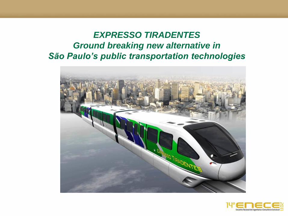
EXPRESSO TIRADENTES
Ground breaking new alternative in
São Paulo’s public transportation technologies

Presentation Structure
Background
•Metropolitan São Paulo Statistics
•Comparison to other Metropolitan Areas
•Metropolitan São Paulo Transportation
•Implementation of Monorail Technology
Structure Characteristics
•Codes on Design
•Loads
•Load Combinations
•Construction Sequence
•Tolerances
•Closure Pours
•Emergency Walkway
•Expansion Joints and Pintel
Structural Components
•Structural Models
•Ride Comfort
•Beams
•Columns
•Foundations
Beam Fabrication
•Precast Yard
•Forms
Summary
•Highlights
•Recognitions
•Questions

Background
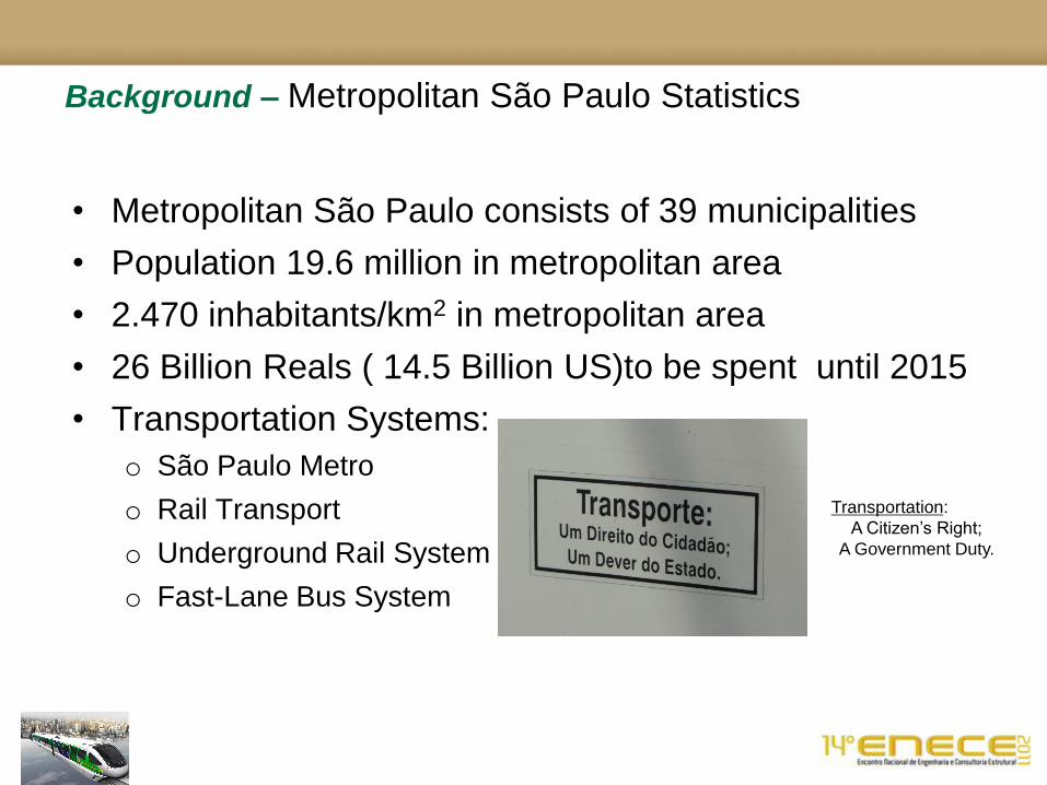
• Metropolitan São Paulo consists of 39 municipalities
• Population 19.6 million in metropolitan area
• 2.470 inhabitants/km2 in metropolitan area
• 26 Billion Reals ( 14.5 Billion US)to be spent until 2015
• Transportation Systems:
o São Paulo Metro
o Rail Transport
o Underground Rail System
o Fast-Lane Bus System
Background – Metropolitan São Paulo Statistics
Transportation:
A Citizen’s Right;
A Government Duty.
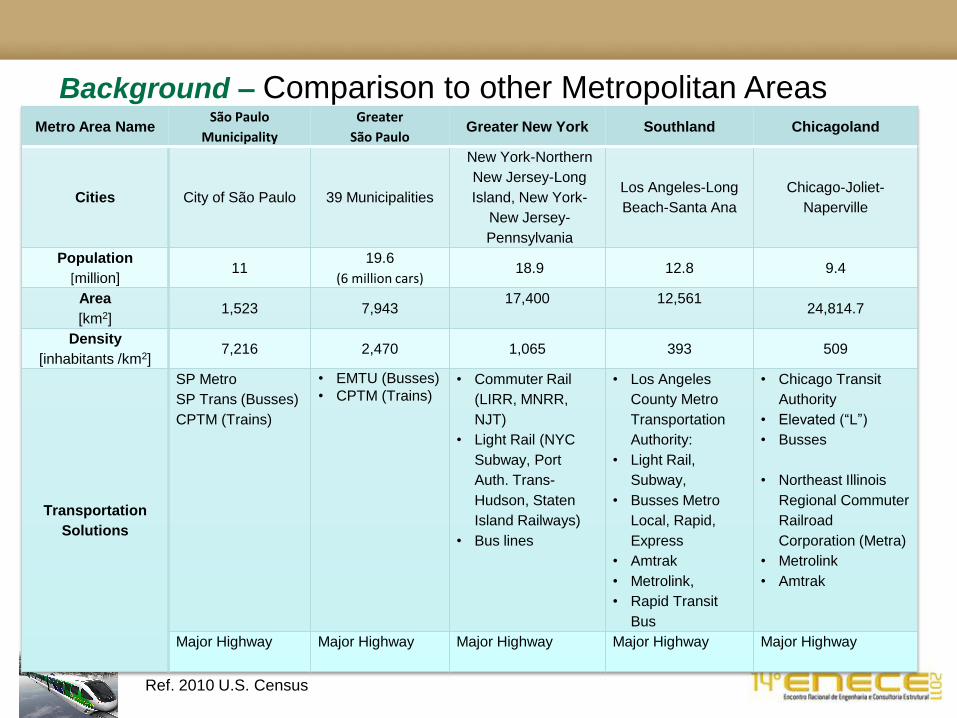
Background – Comparison to other Metropolitan Areas
Ref. 2010 U.S. Census
Metro Area Name São Paulo
Municipality
Greater
São Paulo Greater New York Southland Chicagoland
Cities City of São Paulo 39 Municipalities
New York-Northern
New Jersey-Long
Island, New York-
New Jersey-
Pennsylvania
Los Angeles-Long
Beach-Santa Ana
Chicago-Joliet-
Naperville
Population
[million] 11
19.6
(6 million cars) 18.9 12.8 9.4
Area
[km2] 1,523 7,943
17,400
12,561
24,814.7
Density
[inhabitants /km2] 7,216 2,470 1,065 393 509
Transportation
Solutions
SP Metro
SP Trans (Busses)
CPTM (Trains)
• EMTU (Busses)
• CPTM (Trains)
• Commuter Rail
(LIRR, MNRR,
NJT)
• Light Rail (NYC
Subway, Port
Auth. Trans-
Hudson, Staten
Island Railways)
• Bus lines
• Los Angeles
County Metro
Transportation
Authority:
• Light Rail,
Subway,
• Busses Metro
Local, Rapid,
Express
• Amtrak
• Metrolink,
• Rapid Transit
Bus
• Chicago Transit
Authority
• Elevated (“L”)
• Busses
• Northeast Illinois
Regional Commuter
Railroad
Corporation (Metra)
• Metrolink
• Amtrak
Major Highway
Major Highway
Major Highway
Major Highway
Major Highway

The decision to use monorail technology in the extension of Line 2 was taken in
2009, when the Government of the State of São Paulo and the Prefecture of the
municipality of São Paulo signed an agreement of Technical and Financial
cooperation to substitute the original project for a monorail one that would duplicate
the capacity of the dedicated bus line previously considered.
Current Cost Comparison:
• Highway cost 19.3 million / mile (T-Rex Project)
• HRT Underground: 250 -300 millions / km (www.lrt.daxack.ca)
• LRT Underground: 130 – 225 millions /km (www.lrt.daxack.ca)
• LRT Surface: 20 millions / mile (E. L. Tennyson, P.E)
• LRT Elevated: 78 million / km (PRT Strategies)
• Monorail systems $ 60 million /km (Monorails.org)
Background – Implementation of Monorail Technology

Background –Implementation of Monorail Technology–SP Lines
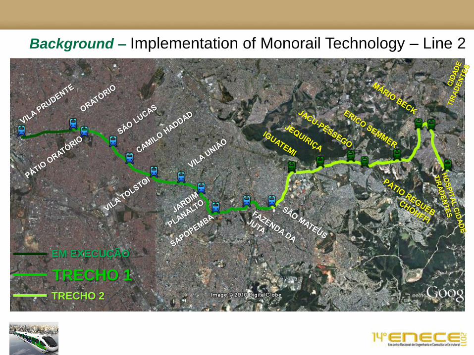
Background – Implementation of Monorail Technology – Line 2
EM EXECUÇÃO
TRECHO 1
TRECHO 2

Background – Implementation of Monorail Technology Line 17

Structure
Characteristics

INTERNATIONAL BID No. 41889213
EXTENSION OF LINE 2 – GREEN VILA PRUDENTE – CIDADE TIRADENTES
Metro SP
ACI 358 Analysis and Design of Reinforced and Prestressed
Concrete Guidebeam Structures.
American Concrete Institute, ACI 358.1R-92
ANSI / ASCE / T&DI 21 Automated People Mover Standards
Part 1 – Operating Environment 21-05
Part 2 – Vehicle and Propulsion 21.2-08
Part 3 – Electrical Systems, Stations, and Guideway 21.3-08
Part 4 - Security, Emergency preparedness
AASHTO LRFD Bridge Design Specifications – US, 4th Edition,
and interims including 2007.
American Association of State Highway and Transportation
Officials.
ACI 318 Building Code and Commentary.
American Concrete Institute, ACI 318-08.
Bombardier Design and Construction Interface Manual
Part 2. Geometric Design BTS Document No. 453-SWD-ICD-010002 R0
Bombardier Design and Construction Interface Manual
Part 2. Part 3 Guideway; BTS Document No. 453-SWD-ICD-010003 R0
ABNT NBR 6118-Projeto de estruturas de concreto
Associação Brasileira de Normas Técnicas. Marzo de
2004
ABNT NBR 6123-Forças devido ao vento em edificações
Associação Brasileira de Normas Técnicas. Junho de
1988
Structure Characteristics – Codes on Design
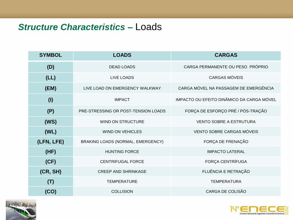
Structure Characteristics – Loads
SYMBOL LOADS CARGAS
(D) DEAD LOADS CARGA PERMANENTE OU PESO PRÓPRIO
(LL) LIVE LOADS CARGAS MÓVEIS
(EM) LIVE LOAD ON EMERGENCY WALKWAY CARGA MÓVEL NA PASSAGEM DE EMERGÊNCIA
(I) IMPACT IMPACTO OU EFEITO DINÂMICO DA CARGA MÓVEL
(P) PRE-STRESSING OR POST-TENSION LOADS FORÇA DE ESFORÇO PRÉ / PÓS-TRAÇÃO
(WS) WIND ON STRUCTURE VENTO SOBRE A ESTRUTURA
(WL) WIND ON VEHICLES VENTO SOBRE CARGAS MÓVEIS
(LFN, LFE) BRAKING LOADS (NORMAL, EMERGENCY) FORÇA DE FRENAÇÃO
(HF) HUNTING FORCE IMPACTO LATERAL
(CF) CENTRIFUGAL FORCE FORÇA CENTRÍFUGA
(CR, SH) CREEP AND SHRINKAGE FLUÊNCIA E RETRAÇÃO
(T) TEMPERATURE TEMPERATURA
(CO) COLLISION CARGA DE COLISÃO

Structure Characteristics – Loads
Condição de carga no de passageiros / trem Carga / Carro
AW0 Vazio 0 15 Tons
AW1 Passageiros sentados 122 pasageiros 16 Tons
AW2 Passageiros sentados + em pé (6 pass/m² a 70 kg) 122 sentados + 880 em pé = 1022 passageiros 25 Tons
AW3 Passageiros sentados + em pé (8 pass/m² a 70 kg) 122 sentados + 1172 em pé= 1294 passageiros 28 Tons
AW4 Passageiros sentados + em pé (10 pass/m² a 70 kg) 122 sentados +1467 em pé= 1589 passageiros 31 Tons

Structure Characteristics – Load Combinations
CARGAS DE SERVIÇO
As cargas de serviço são utilizadas para verificação dos esforços nas vigas e colunas.
O veículo AW2 é utilizado para essa verificação.
COMBINAÇÕES ACI 358
S0= D + 0.9/1.0(PS + CR + SH)
S1= D + 0.9/1.0 (PS + CR + SH) +max of (L+I) or (L + I + LFn) + (CF or HF)
S2= S1 + (0.3(WL + WS)) hor. & vert.
S3= S2 + T
S4 = D + 0.9/1.0 (PS + CR + SH) + max of (WS or EQ) + T
COMBINAÇÕES QUASE PERMANENTE - (CQP)
COMBINAÇÕES FREQUENTE - (CF)
COMBINAÇÕES RARA - (CR)
Todas as cargas permanentes também são combinadas utilizando-se um fator de 0,9 se isto criar uma
combinação pior.
CARGAS DE FADIGA (com base no trabalho de Planservi e Metro)

Structure Characteristics – Load Combinations
ESTADO LIMITE ULTIMO - (ELU)
As cargas de cálculo são utilizadas para verificação das cargas finais na viga guia e nos demais elementos
estruturais.
As cargas do AW4 (ou veículos de controle) são utilizadas para essas combinações.
COMBINAÇÕES ACI 358
U0 = 1.3 D + 0.9/1.2 (PS + CR + SH) + 1.7 (LL+I + CF or HF)
U1 = 1.3 D + 0.9/1.2 (PS + CR + SH) + 1.4 (LL+I + CF or HF) + 1.5(WL + WS)
U2 = 1.3 D + 0.9/1.2 (PS + CR + SH) + 1.4 (LL+I + CF or HF) + WS
U3 = 1.3 D + 0.9/1.2 (PS + CR + SH) + 1.4 (LL+I + CF or HF + LFe) + 1.5T
U6 = 1.3 D + 0.9/1.2 (PS + CR + SH) + CO
U7 = 1.3 D + 0.9/1.2 (PS + CR + SH) + EM
COMBINAÇÕES ÚLTIMAS NORMAIS
COMBINAÇÕES ÚLTIMAS EXCEPCIONAIS
Todas as cargas permanentes também são combinadas utilizando-se um fator de 0,9 se isto criar uma
combinação pior.
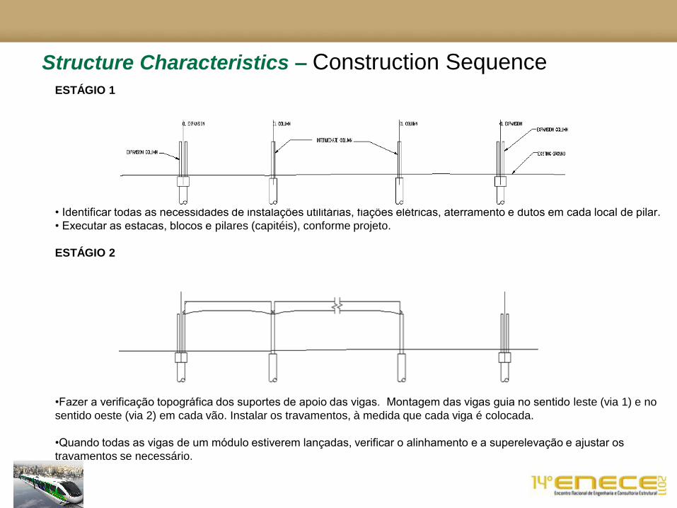
Structure Characteristics – Construction Sequence ESTÁGIO 1
• Identificar todas as necessidades de instalações utilitárias, fiações elétricas, aterramento e dutos em cada local de pilar.
• Executar as estacas, blocos e pilares (capitéis), conforme projeto.
ESTÁGIO 2
•Fazer a verificação topográfica dos suportes de apoio das vigas. Montagem das vigas guia no sentido leste (via 1) e no
sentido oeste (via 2) em cada vão. Instalar os travamentos, à medida que cada viga é colocada.
•Quando todas as vigas de um módulo estiverem lançadas, verificar o alinhamento e a superelevação e ajustar os
travamentos se necessário.
Structure Characteristics – Construction Sequence
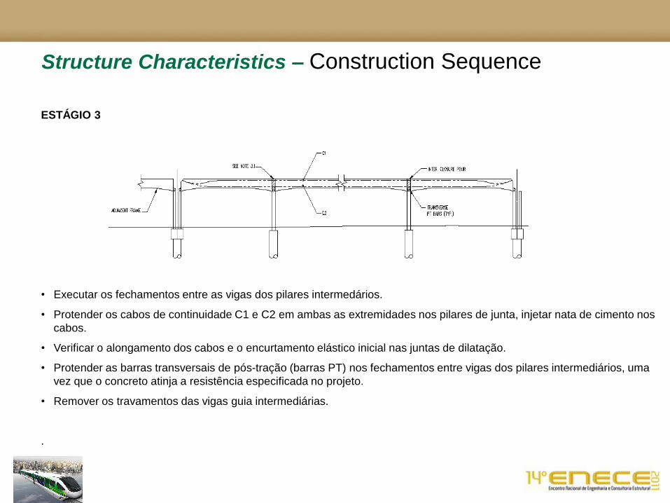
ESTÁGIO 3
• Executar os fechamentos entre as vigas dos pilares intermedários.
• Protender os cabos de continuidade C1 e C2 em ambas as extremidades nos pilares de junta, injetar nata de cimento nos
cabos.
• Verificar o alongamento dos cabos e o encurtamento elástico inicial nas juntas de dilatação.
• Protender as barras transversais de pós-tração (barras PT) nos fechamentos entre vigas dos pilares intermediários, uma
vez que o concreto atinja a resistência especificada no projeto.
• Remover os travamentos das vigas guia intermediárias.
.

Structure Characteristics – Construction Sequence
ESTÁGIO 4
• Executar o fechamento entre vigas dos pilares externos (típicos nos locais de juntas de dilatação), mantendo a junta
entre os módulos. Incluem as placas de expansão e pivô de travamento no fechamento.
• Protender as barras transversais de pós-tração (barras PT) dos fechamentos entre vigas dos pilares externos, uma vez
que o concreto atinja a resistência total.
• Executar a concretagem da segunda fase do fechamento dos pilares intermediários e externos.
• Remover os travamentos das vigas guia, nos pilares externos.
• Instalar passagem de emergência, bandejas de cabos, trilhos de alimentação elétrica e equipamentos relativos.
Lançamento de concreto
fechamento junta
Módulo
adjacente
Barras PT transversais (Típ.)
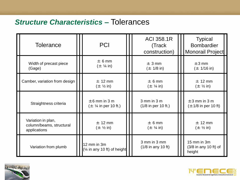
Structure Characteristics – Tolerances
Tolerance
PCI
ACI 358.1R
(Track
construction)
Typical
Bombardier
Monorail Project
Width of precast piece
(Gage)
± 6 mm
(± ¼ in)
± 3 mm
(± 1/8 in)
±3 mm
(± 1/16 in)
Camber, variation from design
± 12 mm
(± ½ in)
± 6 mm
(± ¼ in)
± 12 mm
(± ½ in)
Straightness criteria
±6 mm in 3 m
(± ¼ in per 10 ft.)
3 mm in 3 m
(1/8 in per 10 ft.)
±3 mm in 3 m
(±1/8 in per 10 ft)
Variation in plan,
column/beams, structural
applications
± 12 mm
(± ½ in)
± 6 mm
(± ¼ in)
± 12 mm
(± ½ in)
Variation from plumb
12 mm in 3m
(¼ in any 10 ft) of height
3 mm in 3 mm
(1/8 in any 10 ft)
15 mm in 3m
(3/8 in any 10 ft) of
height

Structure Characteristics – Closure Pours

Structure Characteristics – Emergency Walkway
Bid Time
Early Concept
Current Concept
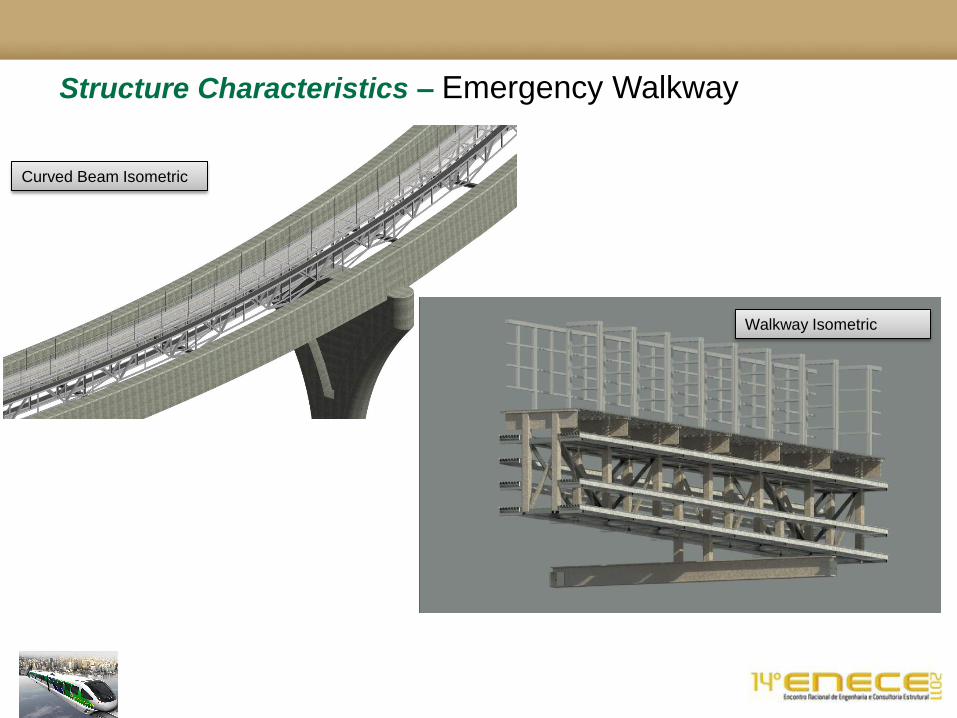
Structure Characteristics – Emergency Walkway
Curved Beam Isometric
Walkway Isometric
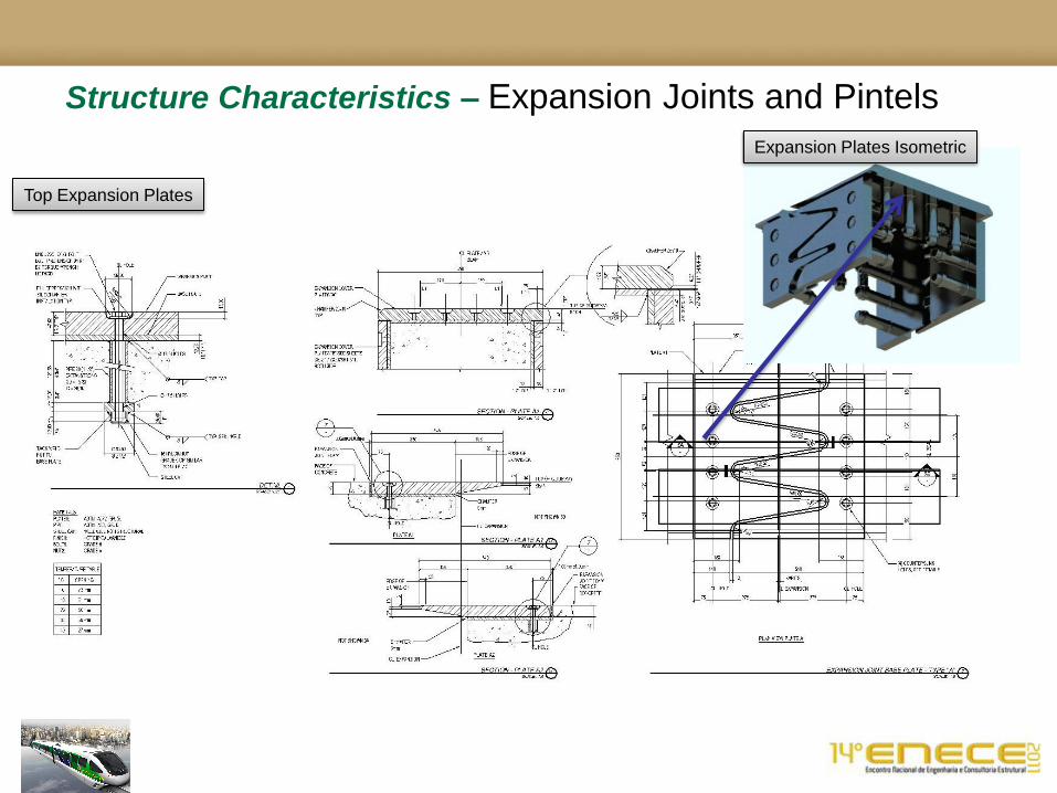
Structure Characteristics – Expansion Joints and Pintels
Top Expansion Plates
Expansion Plates Isometric
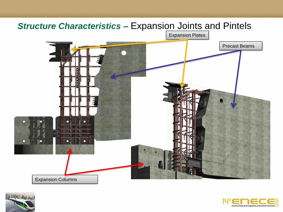
Structure Characteristics – Expansion Joints and Pintels
Expansion Plates
Precast Beams
Expansion Columns
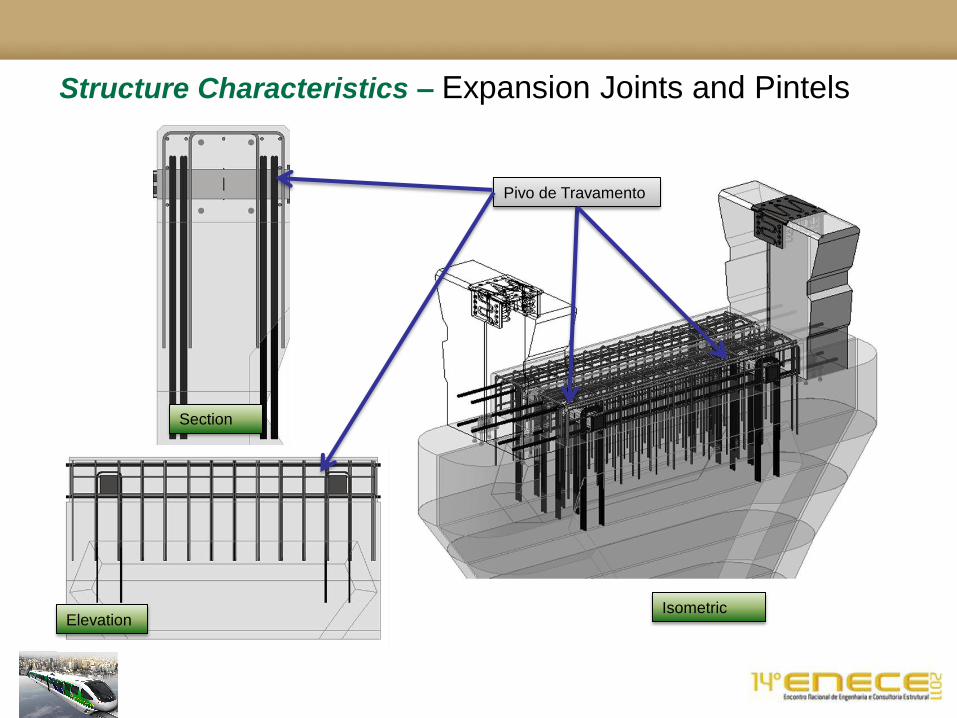
Structure Characteristics – Expansion Joints and Pintels
Pivo de Travamento
Isometric Elevation
Section
Structural
Components
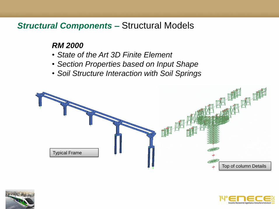
Structural Components – Structural Models
RM 2000
• State of the Art 3D Finite Element
• Section Properties based on Input Shape
• Soil Structure Interaction with Soil Springs
Typical Frame
Top of column Details
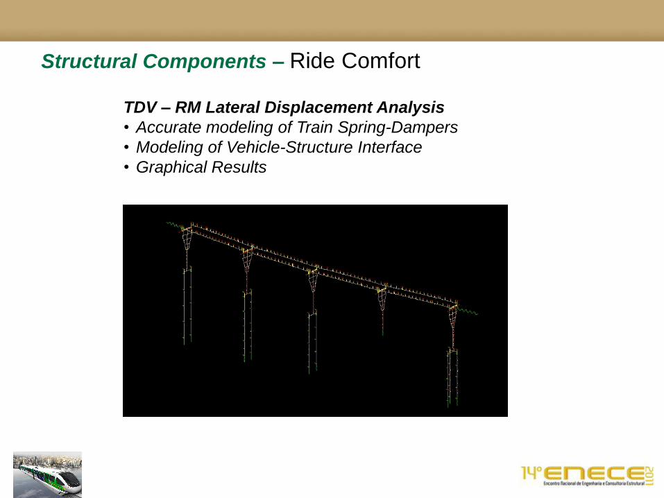
Structural Components – Ride Comfort
TDV – RM Lateral Displacement Analysis
• Accurate modeling of Train Spring-Dampers
• Modeling of Vehicle-Structure Interface
• Graphical Results

Structural Components – Beams
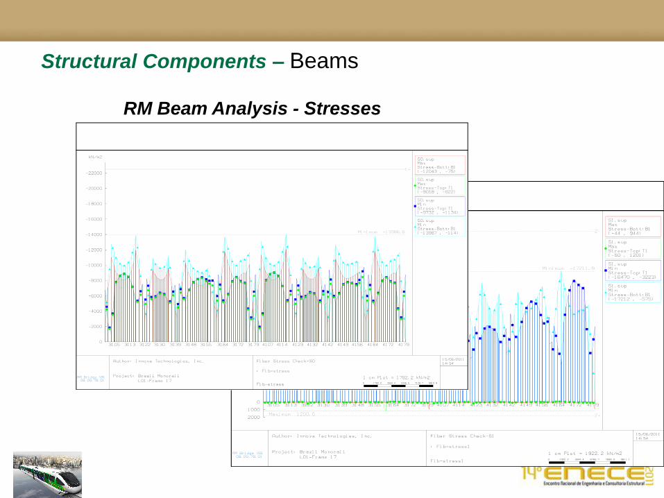
Structural Components – Beams
RM Beam Analysis - Stresses

Structural Components – Beams
RM Beam Analysis – Demand Displays
Exemplo de Carga de Cálculo Caso U4 – Gráfico dos momentos Mz
Monotrilho Brasil U4 Carga fatorada
max Mz – momento de flexao
min Mz - momento de flexao

Structural Components – Beams
RM Beam Analysis – Factored Loads
Factored Load Checks: My (weak axis)
Demand and Capacity Checks
Factored Load Checks: Mz (strong axis)
Demand and Capacity Check
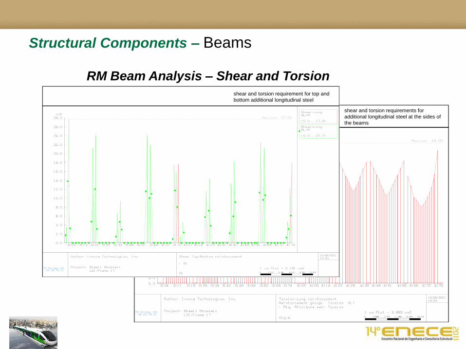
Structural Components – Beams
RM Beam Analysis – Shear and Torsion
shear and torsion requirements for
additional longitudinal steel at the sides of
the beams
shear and torsion requirement for top and
bottom additional longitudinal steel

Structural Components – Beams
RM Beam Analysis – Shear and Torsion
The following diagram shows the shear and torsion steel required-stirrups:
• Blue Lines AVQT are Torsion Requirements
• Red Lines AVQ are Shear Requirements
Both of these quantities are provided for in the design drawings provided with these calculations.

Structural Components – Columns

Structural Components – Foundations

Beam Fabrication
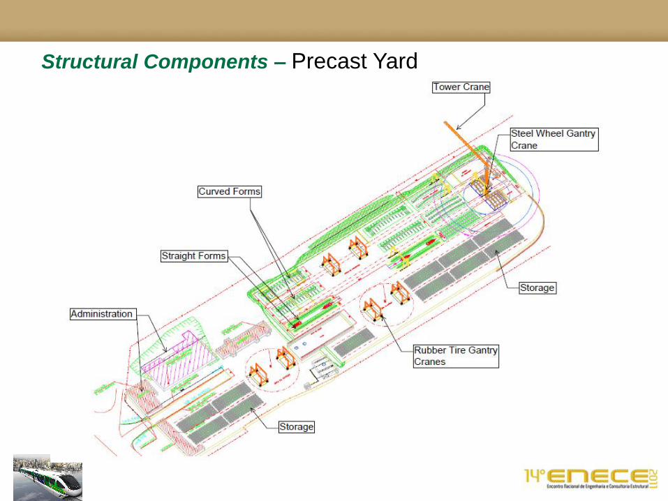
Structural Components – Precast Yard
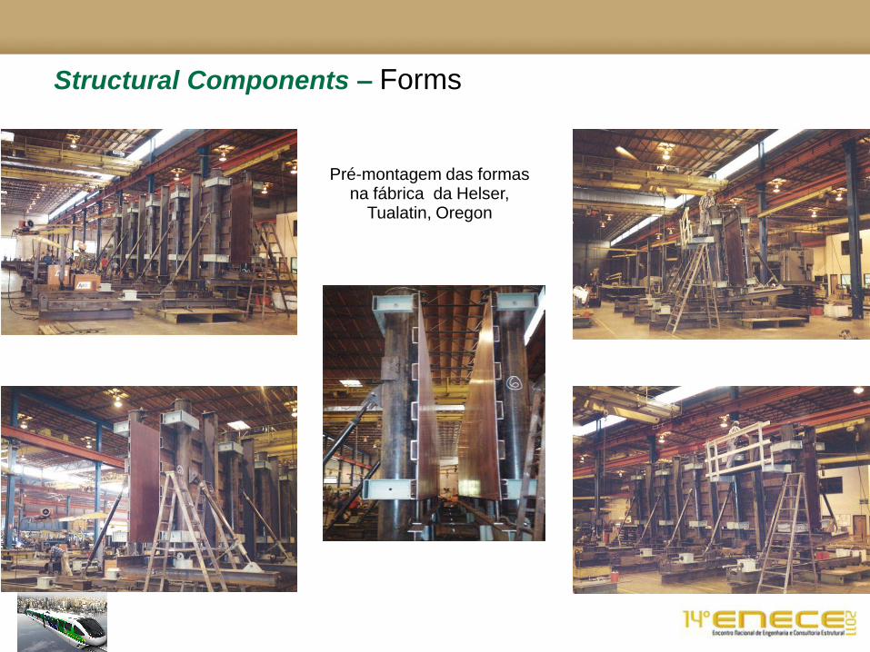
Structural Components – Forms
Pré-montagem das formas na fábrica da Helser,
Tualatin, Oregon

Structural Components – Forms

Structural Components – Forms
Vista da forma em perfil
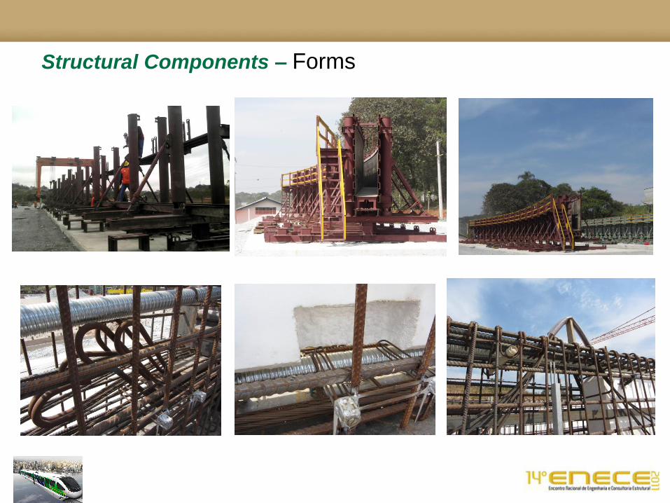
Structural Components – Forms

Summary
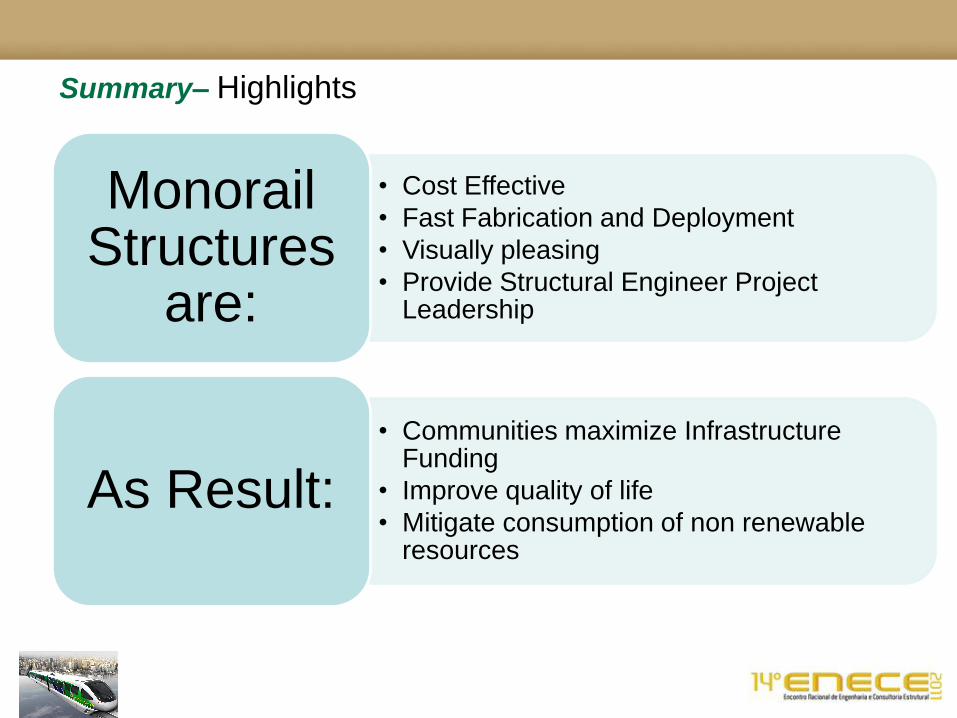
• Cost Effective
• Fast Fabrication and Deployment
• Visually pleasing
• Provide Structural Engineer Project Leadership
Monorail Structures
are:
• Communities maximize Infrastructure Funding
• Improve quality of life
• Mitigate consumption of non renewable resources
As Result:
Summary– Highlights
Summary– Recognition
Bentley – RM / Innova:
•Marcos Beier
•Adriana Gonorazky
•Steve Moore
•Laura Thompson
•Huijun Dong
•Robert Naples
•Ben Hicks
•Stephen Cupp
•Michael Shipler
•Alan Saastad
Metro SP:
•Paulo Meca
•Orlando Ferreira
•Deborah XXXX
•Ary Toledo
• Ivan Piccoli
Construtora Queiroz Galvao:
•Jose Henrique de Avila
•Adriano Cunha
•Francisco de Asis Serafim
•Henrique Ferraz
•Marcos Viena Pecly
CEML, Consortio Monotrilho Leste:
•Fernando de Oliviera Gomes
•Antonio Carlos do Nascimento
•Arthur Venuto
•Nadia Moura de Souza
•Jose Evandro Santos
Bombardier Transportation
•Chris Fifield
• Ivan Vrabac
•Sarah Byers
•Bob Needermeyer
•Nelson Aidar
•Pat McGinley
•Bruce MacDonald
•Doug Heitzenrater
•Halil Oznan
•Jayson Nestor
Planservi
•Carlos Akira Murakami
•Silvia Silmão
•Eder Toshio Iguti
•Roberta Leopoldo e Silva
•Jean Le Guevellou
•Marcos Silva
Setepla / Tecnifer
•Yanagi Yoshiaki
•Marcio Cecci
PROENGE
•Valter Braga
•Marc André Chamouton
•Alberto Vitale
Zamarion Millen / Nucleo
•Eduardo Barros Millen
•Rogerio Martinati
•Murilo Martins
And the many
more not named,
but who made this
project possible
with their daily
interfaces with the
principal author
T H A N K Y O U - O B R I G A D O

Summary– Questions?
Top Related