12 Ligações Semi-Rígidas - Placa de Base · of pinned column bases. 2 2. ... . Title: Microsoft...
13
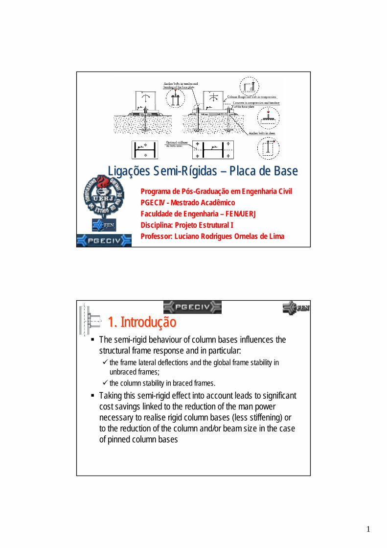
1 Programa de Pós-Graduação em Engenharia Civil PGECIV - Mestrado Acadêmico Faculdade de Engenharia – FEN/UERJ Disciplina: Projeto Estrutural I Professor: Luciano Rodrigues Ornelas de Lima Liga Ligaç ões ões Semi Semi-Rí gidas gidas – Placa de Base Placa de Base 1. Introdu 1. Introduç ão ão The semi-rigid behaviour of column bases influences the structural frame response and in particular: the frame lateral deflections and the global frame stability in unbraced frames; the column stability in braced frames. Taking this semi-rigid effect into account leads to significant cost savings linked to the reduction of the man power necessary to realise rigid column bases (less stiffening) or to the reduction of the column and/or beam size in the case of pinned column bases
Transcript of 12 Ligações Semi-Rígidas - Placa de Base · of pinned column bases. 2 2. ... . Title: Microsoft...
1
Programa de Pós-Graduação em Engenharia CivilPGECIV - Mestrado AcadêmicoFaculdade de Engenharia – FEN/UERJDisciplina: Projeto Estrutural IProfessor: Luciano Rodrigues Ornelas de Lima
LigaLigaçções ões SemiSemi--RRíígidasgidas –– Placa de BasePlaca de Base
1. Introdu1. IntroduççãoãoThe semi-rigid behaviour of column bases influences the structural frame response and in particular:
the frame lateral deflections and the global frame stability in unbraced frames;the column stability in braced frames.
Taking this semi-rigid effect into account leads to significant cost savings linked to the reduction of the man power necessary to realise rigid column bases (less stiffening) or to the reduction of the column and/or beam size in the case of pinned column bases
2
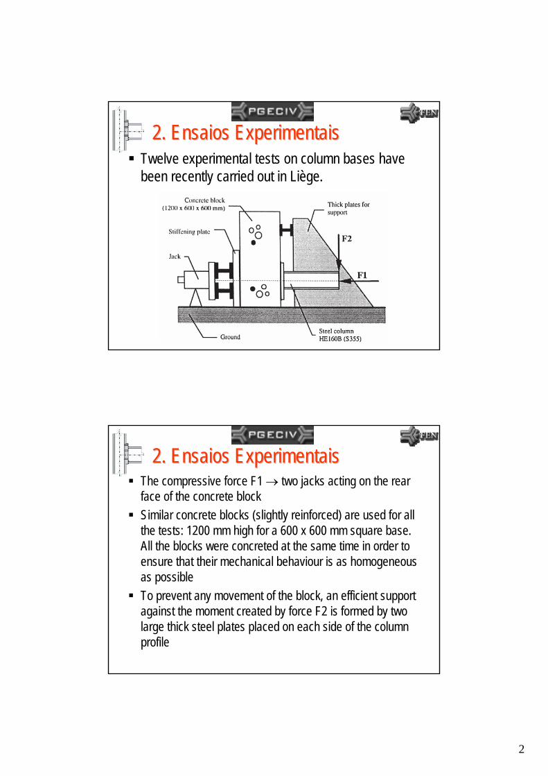
2. Ensaios Experimentais2. Ensaios ExperimentaisTwelve experimental tests on column bases have been recently carried out in Liège.
2. Ensaios Experimentais2. Ensaios ExperimentaisThe compressive force F1 → two jacks acting on the rear face of the concrete block Similar concrete blocks (slightly reinforced) are used for all the tests: 1200 mm high for a 600 x 600 mm square base. All the blocks were concreted at the same time in order to ensure that their mechanical behaviour is as homogeneous as possibleTo prevent any movement of the block, an efficient support against the moment created by force F2 is formed by two large thick steel plates placed on each side of the column profile
3
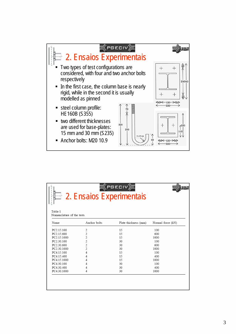
2. Ensaios Experimentais2. Ensaios ExperimentaisTwo types of test configurations are considered, with four and two anchor bolts respectivelyIn the first case, the column base is nearly rigid, while in the second it is usually modelled as pinnedsteel column profile: HE160B (S355)two different thicknesses are used for base-plates: 15 mm and 30 mm (S235)Anchor bolts: M20 10.9
2. Ensaios Experimentais2. Ensaios Experimentais
4
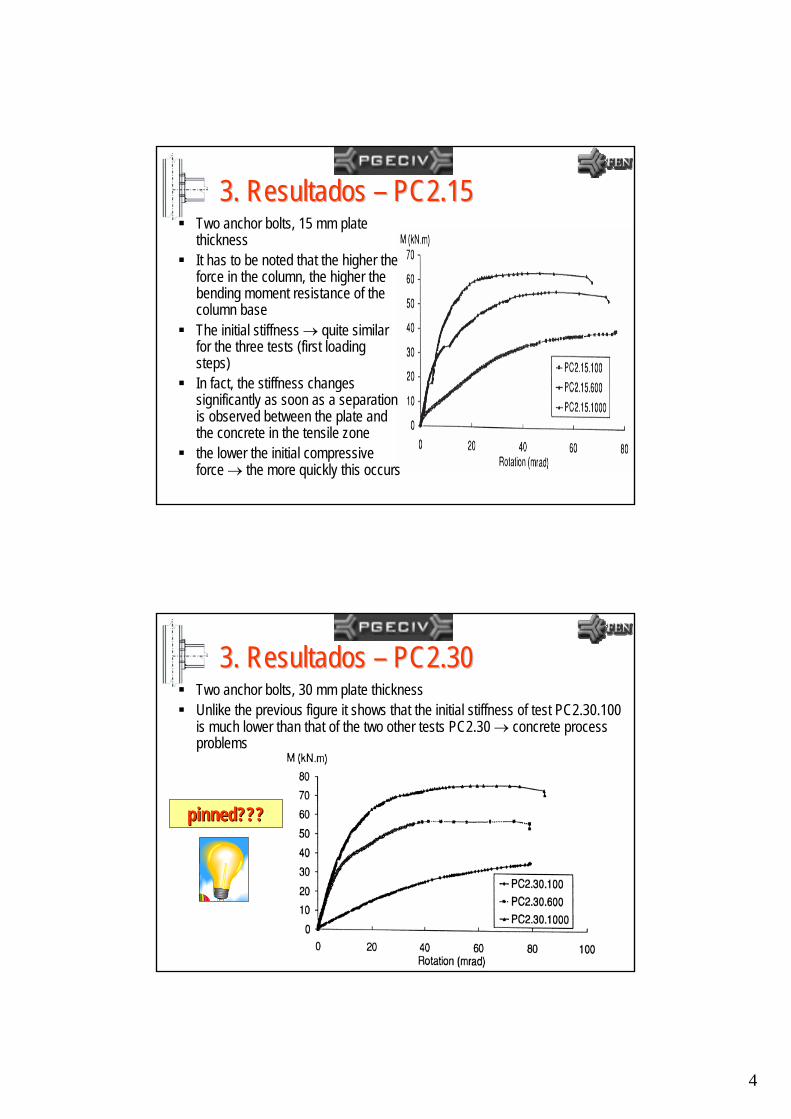
3. Resultados 3. Resultados –– PC2.15PC2.15Two anchor bolts, 15 mm plate thicknessIt has to be noted that the higher the force in the column, the higher the bending moment resistance of the column baseThe initial stiffness → quite similar for the three tests (first loading steps)In fact, the stiffness changes significantly as soon as a separation is observed between the plate and the concrete in the tensile zonethe lower the initial compressive force → the more quickly this occurs
3. Resultados 3. Resultados –– PC2.30PC2.30Two anchor bolts, 30 mm plate thicknessUnlike the previous figure it shows that the initial stiffness of test PC2.30.100 is much lower than that of the two other tests PC2.30 → concrete process problems
pinned???pinned???

5
3. Resultados 3. Resultados –– PC4.15PC4.15Four anchor bolts, 15 mm plate thicknessThe significant difference in strength between test PC4.15.1000 and the two other tests PC4.15 has to be pointed out. This may be explained by the fact that the anchor bolts in tension are activated much later when the compressive force in the column is high
3. Resultados 3. Resultados –– PC4.30PC4.30Four anchor bolts, 30 mm plate thicknessUnlike the three previous figures, it has to be noted that test PC4.30.1000 does not exhibit a higher strength than test PC4.30.400. In fact, this is due to the yielding, at the end of the test, of the end section of the steel HE160B profile. In addition, local plate buckling is also observed in the column flange subjected to the higher compressive stresses.
6
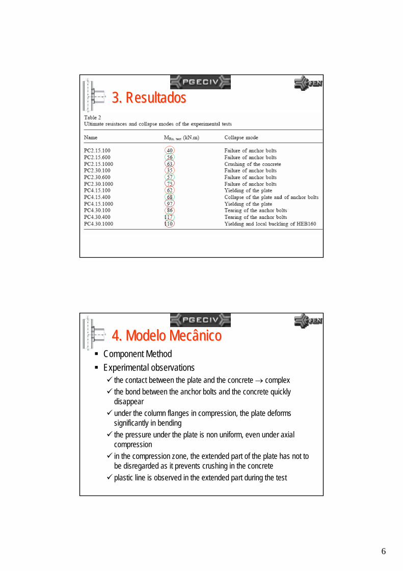
3. Resultados3. Resultados
4. Modelo Mecânico4. Modelo MecânicoComponent MethodExperimental observations
the contact between the plate and the concrete → complexthe bond between the anchor bolts and the concrete quickly disappearunder the column flanges in compression, the plate deforms significantly in bendingthe pressure under the plate is non uniform, even under axial compressionin the compression zone, the extended part of the plate has not to be disregarded as it prevents crushing in the concreteplastic line is observed in the extended part during the test
7
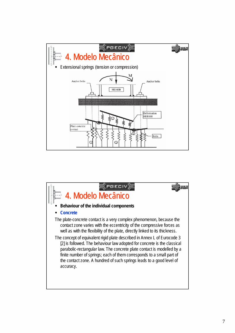
4. Modelo Mecânico4. Modelo MecânicoExtensional springs (tension or compression)
4. Modelo Mecânico4. Modelo MecânicoBehaviour of the individual componentsConcrete
The plate-concrete contact is a very complex phenomenon, because the contact zone varies with the eccentricity of the compressive forces as well as with the flexibility of the plate, directly linked to its thickness.
The concept of equivalent rigid plate described in Annex L of Eurocode 3 [2] is followed. The behaviour law adopted for concrete is the classical parabolic-rectangular law. The concrete plate contact is modelled by a finite number of springs; each of them corresponds to a small part of the contact zone. A hundred of such springs leads to a good level of accuracy.
8
4. Modelo Mecânico4. Modelo MecânicoBehaviour of the individual componentsAnchor bolts and plate in tension
The local response of the anchor bolts in tension and of the plate depends on the thickness of the plate and on the position of the bolt rows: inside or outside the flange.
EUROCODE 3 is used for the determination of the behaviour curve of these components. For some tests with thick base plates, it has been assumed that no prying effect occurs between the concrete and the edge of the end-plate in the tension zone. This assumption is justified as follows: the anchor bolts have a very high deformability; therefore the resulting relative displacement between the plate and the concrete is significant, sufficiently to be considered as higher than that due to the flexural deformation of the plate.
4. Modelo Mecânico4. Modelo MecânicoBehaviour of the individual componentsPlate in compression
In the compression zone, the plate also deforms. Tests have shown that this deformation is very local and can be assimilated to a plastic hinge. This one is modelled through the use of a spring in bending characterized by an elastic-plastic law in the compression zone. This spring is infinitely rigid in the tension zone, the deformation of the base-plate being covered then by that of the ‘anchor bolts and plate in tension’ component.The steel profile
Because of the high normal forces in the column, this one might partially yield. An elastic-plastic behaviour law is adopted for the related springs. The possible plate buckling of the column flanges and/or web in compression is not yet covered by the model.
9
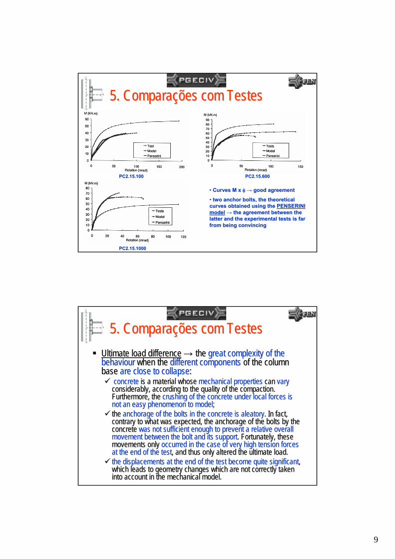
5. Compara5. Comparaçções com Testesões com Testes
PC2.15.1000PC2.15.1000
PC2.15.100PC2.15.100 PC2.15.600PC2.15.600
•• Curves M x Curves M x φφ→→ good agreementgood agreement
•• two anchor bolts, the theoretical two anchor bolts, the theoretical curves obtained using the curves obtained using the PENSERINI PENSERINI modelmodel →→ the agreement between the the agreement between the latter and the experimental tests is far latter and the experimental tests is far from from being convincingbeing convincing
5. Compara5. Comparaçções com Testesões com TestesUltimate load differenceUltimate load difference →→ the the great complexity of the great complexity of the behaviourbehaviour when the when the different componentsdifferent components of the column of the column base base are close to collapseare close to collapse::
concrete concrete is a material whose is a material whose mechanical propertiesmechanical properties can can vary vary considerably, according to the quality of the compaction. considerably, according to the quality of the compaction. Furthermore, the Furthermore, the crushing of the concrete under local forces is crushing of the concrete under local forces is not an easy phenomenon to model;not an easy phenomenon to model;the the anchorage of the bolts in the concrete is anchorage of the bolts in the concrete is aleatoryaleatory. In fact, . In fact, contrary to what was expected, the anchorage of the bolts by thecontrary to what was expected, the anchorage of the bolts by theconcrete concrete was not sufficient enough to prevent a relative overall was not sufficient enough to prevent a relative overall movement between the bolt and its supportmovement between the bolt and its support. Fortunately, these . Fortunately, these movements only movements only occurred in the case of very high tension forces occurred in the case of very high tension forces at the end of the testat the end of the test, and thus only altered the ultimate load., and thus only altered the ultimate load.the displacements at the end of the test become quite significanthe displacements at the end of the test become quite significantt, , which leads to geometry changes which are not correctly taken which leads to geometry changes which are not correctly taken into account in the mechanical model.into account in the mechanical model.
10
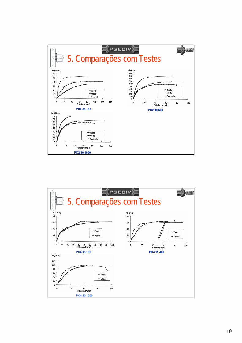
5. Compara5. Comparaçções com Testesões com Testes
PC2.30.100PC2.30.100 PC2.30.600PC2.30.600
PC2.30.1000PC2.30.1000
5. Compara5. Comparaçções com Testesões com Testes
PC4.15.100PC4.15.100 PC4.15.400PC4.15.400
PC4.15.1000PC4.15.1000

11
5. Compara5. Comparaçções com Testesões com Testes
PC4.30.100PC4.30.100 PC4.30.400PC4.30.400
PC4.30.1000PC4.30.1000
•• PC4.30.400 (Fig. 20) PC4.30.400 (Fig. 20) →→ excellent resultsexcellent results
•• PC4.30.100 PC4.30.100 →→ same problem as test same problem as test PC2.30.100, i.e. an actual stiffness for the PC2.30.100, i.e. an actual stiffness for the concrete lower than the theoretical concrete lower than the theoretical predictionprediction
•• PC4.30.1000 seems to be well described by PC4.30.1000 seems to be well described by the mechanical model when the moment is the mechanical model when the moment is lower than half its ultimate value.lower than half its ultimate value.
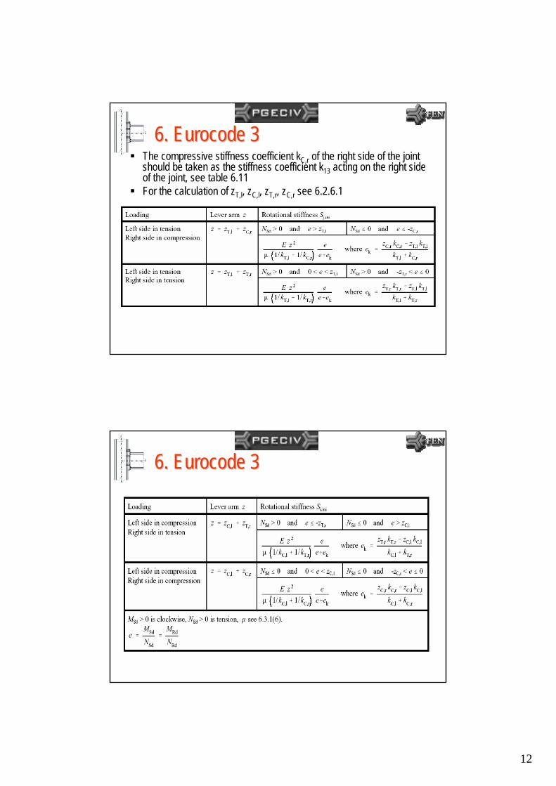
6. Eurocode 36. Eurocode 3The rotational stiffness Sj of a column base for normal force in combination with bending moment may be determined with table 6.12 where the contribution of the concrete portion just under the column web (T-stub 2 of figure 6.20) to the rotational stiffness is omittedThe tension stiffness coefficient kT,l of the left side of the joint should be taken as the sum of the stiffness coefficients k15 and k16 acting on the left side of the joint, see table 6.11The tension stiffness coefficient kT,r of the right side of the joint should be taken as the sum of the stiffness coefficients k15 (base plate in bending) and k16 (anchor bolt in tension) acting on the right side of the joint, see table 6.11The compressive stiffness coefficient kC,l of the left side of the joint should be taken as the stiffness coefficient k13 (concrete in compression) acting on the left side of the joint, see table 6.11
12
The compressive stiffness coefficient kC,r of the right side of the joint should be taken as the stiffness coefficient k13 acting on the right side of the joint, see table 6.11For the calculation of zT,l, zC,l, zT,r, zC,r see 6.2.6.1
6. Eurocode 36. Eurocode 3
6. Eurocode 36. Eurocode 3
13
6. Eurocode 36. Eurocode 3
Artigo J. P. Artigo J. P. JaspartJaspart::PPáágina da CAPES: gina da CAPES: www.capes.gov.brwww.capes.gov.brentrar em perientrar em perióódicos e depois, na letra J dicos e depois, na letra J –– JournalJournal ofofConstructionalConstructional SteelSteel Research Research –– volume 48 (1998) volume 48 (1998) ––ppááginas 89ginas 89--106106Application of the component method to column Application of the component method to column bases bases -- J.P. J.P. JaspartJaspart and D. and D. VandegansbVandegansb
Material ECCS:Material ECCS:http://openlink.br.inter.net/lucianolima/baseplates_ECCS.pdfhttp://openlink.br.inter.net/lucianolima/baseplates_ECCS.pdf


![Análise Inelástica de Segunda Ordem de Estruturas ......Análise inelástica de segunda ordem de estruturas metálicas com ligações semi-rígidas [manuscrito]. / Paulo Anderson](https://static.fdocumentos.com/doc/165x107/61158360e002703c9d3e5184/anlise-inelstica-de-segunda-ordem-de-estruturas-anlise-inelstica.jpg)