
A Scalable and Versatile Framework for Smart Video...
87
A SCALABLE AND VERSATILE FRAMEWORK FOR SMART VIDEO SURVEILLANCE
Transcript of A Scalable and Versatile Framework for Smart Video...

A SCALABLE AND VERSATILE FRAMEWORK FOR
SMART VIDEO SURVEILLANCE


ANTONIO CARLOS DE NAZARÉ JÚNIOR
A SCALABLE AND VERSATILE FRAMEWORK FOR
SMART VIDEO SURVEILLANCE
Dissertação apresentada ao Programade Pós-Graduação em Ciência da Com-putação do Instituto de Ciências Exatasda Universidade Federal de Minas Geraiscomo requisito parcial para a obtençãodo grau de Mestre em Ciência da Com-putação.
ORIENTADOR: WILLIAM ROBSOM SCHWARTZ
COORIENTADOR: RENATO ANTONIO CELSO FERREIRA
Belo Horizonte
Setembro de 2014

ANTONIO CARLOS DE NAZARÉ JÚNIOR
A SCALABLE AND VERSATILE FRAMEWORK FOR
SMART VIDEO SURVEILLANCE
Dissertation presented to the GraduateProgram in Computer Science of the Fed-eral University of Minas Gerais in partialfulfillment of the requirements for the de-gree of Master in Computer Science.
ADVISOR: WILLIAM ROBSOM SCHWARTZ
CO-ADVISOR: RENATO ANTONIO CELSO FERREIRA
Belo Horizonte
September 2014

c© 2014, Antonio Carlos de Nazaré Júnior.Todos os direitos reservados.
Ficha catalografica elaborada pela Biblioteca do ICEx – UFMG
Nazaré Júnior, Antonio Carlos de
N335s A Scalable and Versatile Framework for Smart VideoSurveillance / Antonio Carlos de Nazaré Júnior. — BeloHorizonte, 2014
xxvi, 61 f. : il. ; 29cm
Dissertação (mestrado) — Universidade Federal deMinas Gerais - Departamento de Ciência da Computação
Orientador: William Robsom SchwartzCoorientador: Renato Antonio Celso Ferreira
1. Computação – Teses. 2. Visão por computador – Teses.3. Gravações de video - Sistemas de segurança – Teses.I. Orientador. II. Coorientador. III. Título.
CDU 519.6*82.10(043)


To Ronaldo Ferreira da Cunha, for believing in me from the beginning.
ix


Acknowledgments
I am extremely grateful to my family, specially my parents Antonio Carlos deNazaré and Inês Conceição Reis de Nazaré for their continuous and unconditionallove, for always believing in me, and for their support in my decisions and I am verygrateful to Flávia Alvarenga, for her patience, companionship and love throughoutmy course.
I also would like to express my sincere gratitude to my advisor Prof. WilliamRobson Schwartz. His entrepreneurship, experience, sincerity, critical view, andfocus on results helped shape this thesis, and contributed considerably to my pathtowards an academic and research career. I am also grateful to Prof. Renato Ferreira,my co-advisor, for the contributions to the development of this Master’s Thesis.
I thank my labmates at the SSIG, in particularly Victor Hugo Cunha de Melo,Cássio Elias Jr. and Marco Túlio Alves, for the stimulating discussions and for thesleepless nights we were working before deadlines. Also, I thank my colleaguesin Federal University of Minas Gerais: Suellen Almeida, Itamar Hata, RobertoOliveira, Angelo Assis, Thales Filizola, Alex de Sá, Carlos Caetano, AlessandroSena, Renato Miranda, Heitor Motta, Phillipe Samer, Rosklin Juliano, Samuel Evan-gelista, Sabir Ribas and Bruno Coutinho.
A special thanks to David Menotti, for the sincere friendship.Lastly, I thank the partial support given by the Brazilian government, particu-
larly the CAPES and CNPQ for the financial support.
xi


“Divide each difficulty into as many parts as is feasibleand necessary to resolve it.”
(René Descartes)
xiii

Abstract
The availability of surveillance cameras placed in public locations has increasedvastly in the last years, providing a safe environment for people at the cost of hugeamount of visual data collected. Such data are mostly processed manually, a taskwhich is labor intensive and prone to errors. Therefore, automatic approaches mustbe employed to enable the processing of the data, so that human operators onlyneed to reason about selected portions.
Focused on solving problems in the domain of visual surveillance, computervision problems applied to this domain have been developed for several years aim-ing at finding accurate and efficient solutions, required to allow the execution ofsurveillance systems in real environments. The main goal of such systems is to an-alyze the scene focusing on the detection and recognition of suspicious activitiesperformed by humans in the scene, so that the security staff can pay closer atten-tion to these preselected activities. However these systems are rarely tackled in ascalable manner.
Before developing a full surveillance system, several problems have to besolved first, for instance: background subtraction, person detection, tracking and re-identification, face recognition, and action recognition. Even though each of theseproblems have been researched in the past decades, they are hardly considered in asequence. Each one is usually solved individually. However, in a real surveillancescenario, the aforementioned problems have to be solved in sequence consideringonly videos as the input.
Aiming at the direction of evaluating approaches in more realistic scenarios,this work proposes a framework called Smart Surveillance Framework (SSF), to al-low researchers to implement their solutions to the above problems as a sequence ofprocessing modules that communicates through a shared memory.
The SSF is a C++ library built to provide important features for a surveil-lance system, such as a automatic scene understanding, scalability, real-time oper-ation, multi-sensor environment, usage of low cost standard components, runtime
xv

re-configuration, and communication control.
xvi

Resumo
A disponibilidade de câmeras de vigilância dispostas em locais públicos tem au-mentado significativamente nos últimos anos, provendo um ambiente seguro parasas pessoas ao custo de uma enorme quantidade de dados visuais coletada. Estesdados são, em sua maioria, processados manualmente, uma tarefa que é trabalhosae propensa a erros. Entretanto, é desejável que abordagens automáticas possam serutilizadas no processamento dos dados, de modo que os operadores humanos ne-cessitem tomar decisões apenas em determinados momentos.
Focados em solucionar problemas no domínio de vigilância visual, técnicasde visão computacional aplicadas a este domínio têm sido desenvolvidas durantevários anos com o objetivo de encontrar soluções precisas e eficientes, necessáriaspara permitir a execução de sistemas de vigilância em ambientes reais. O principalobjetivos destes sistemas é a análise de cenas focando na detecção e reconhecimentode atividades suspeitas efetuadas por humanos, para que a equipe de segurançapossa focar sua atenção nestas atividades pré-selecionadas. Entretanto estes sis-temas são raramente escaláveis.
Antes de desenvolver um sistema de vigilância completo, é necessário re-solver vários problemas, por exemplo: remoção de fundo, detecção de pessoas, ras-treamento e re-identificação, reconhecimento de faces e reconhecimento de ações.Mesmo que cada um destes problemas tenham sido estudado nas últimas décadas,eles são dificilmente considerados como uma sequência. Cada um é geralmentesolucionado de forma individual. No entanto, em um ambiente real de vigilância,os problemas citados precisam ser solucionados em ordem, considerando apenas ovídeo como a entrada.
Com o objetivo de avaliar abordagens em um cenário mais realista, este tra-balho propõe um framework chamado Smart Surveillance Framework (SSF), que per-mite os pesquisadores a implementar suas soluções para os problemas acima citadoscomo uma sequência de módulos de processamento que se comunicam por meio deuma memória compartilhada.
xvii

O SSF é uma biblioteca C++ desenvolvida para prover características impor-tantes a um sistema de vigilância como: uma interpretação automática das cenas,escalabilidade, operações em tempo real, ambientes multi-sensores, utilização decomponentes padrões de baixo custo, reconfiguração em tempo de execução e con-trole da comunicação.
xviii
List of Figures
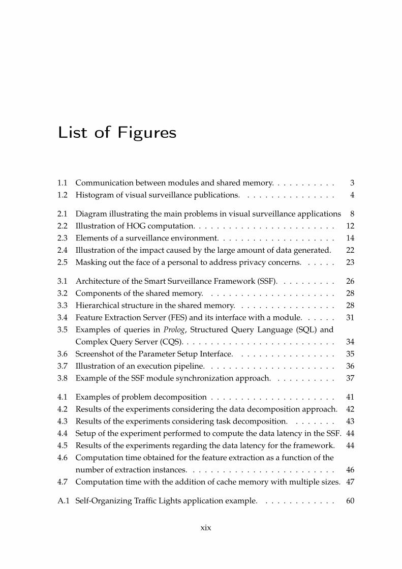
1.1 Communication between modules and shared memory. . . . . . . . . . . 31.2 Histogram of visual surveillance publications. . . . . . . . . . . . . . . . 4
2.1 Diagram illustrating the main problems in visual surveillance applications 82.2 Illustration of HOG computation. . . . . . . . . . . . . . . . . . . . . . . . 122.3 Elements of a surveillance environment. . . . . . . . . . . . . . . . . . . . 142.4 Illustration of the impact caused by the large amount of data generated. 222.5 Masking out the face of a personal to address privacy concerns. . . . . . 23
3.1 Architecture of the Smart Surveillance Framework (SSF). . . . . . . . . . 263.2 Components of the shared memory. . . . . . . . . . . . . . . . . . . . . . 283.3 Hierarchical structure in the shared memory. . . . . . . . . . . . . . . . . 283.4 Feature Extraction Server (FES) and its interface with a module. . . . . . 313.5 Examples of queries in Prolog, Structured Query Language (SQL) and
Complex Query Server (CQS). . . . . . . . . . . . . . . . . . . . . . . . . . 343.6 Screenshot of the Parameter Setup Interface. . . . . . . . . . . . . . . . . 353.7 Illustration of an execution pipeline. . . . . . . . . . . . . . . . . . . . . . 363.8 Example of the SSF module synchronization approach. . . . . . . . . . . 37
4.1 Examples of problem decomposition . . . . . . . . . . . . . . . . . . . . . 414.2 Results of the experiments considering the data decomposition approach. 424.3 Results of the experiments considering task decomposition. . . . . . . . 434.4 Setup of the experiment performed to compute the data latency in the SSF. 444.5 Results of the experiments regarding the data latency for the framework. 444.6 Computation time obtained for the feature extraction as a function of the
number of extraction instances. . . . . . . . . . . . . . . . . . . . . . . . . 464.7 Computation time with the addition of cache memory with multiple sizes. 47
A.1 Self-Organizing Traffic Lights application example. . . . . . . . . . . . . 60
xix


List of Tables
2.1 Overview of computer vision problems applied to visual surveillance. . 102.2 Summary of technical evolution of intelligent surveillance systems.
(Adapted from [Valera and Velastin, 2005]). . . . . . . . . . . . . . . . . . 15
xxi


List of Acronyms
CCTV Closed-Circuit Television
CQS Complex Query Server
FES Feature Extraction Server
FPS Frames per Second
GLCM Gray-Level Co-occurrence Matrix
GPGPU General Purpose Graphics Processing Unit
GUI Graphical User Interface
HOG Histogram of Oriented Gradients
LAP Looking at People
OpenCV Open Source Computer Vision Library
PTZ Pan–tilt–zoom
S3 IBM Smart Surveillance System
SIFT Scale Invariant Feature Transformation
SISS Software Infrastructure for Smart Space
SQL Structured Query Language
SSD solid-state drive
SSF Smart Surveillance Framework
STL C++ Standard Template Library
VSAM Video Surveillance and Monitoring
xxiii


Contents
Acknowledgments xi
Abstract xv
Resumo xvii
List of Figures xix
List of Tables xxi
List of Acronyms xxiii
1 Introduction 11.1 Motivation . . . . . . . . . . . . . . . . . . . . . . . . . . . . . . . . . . 31.2 Dissertation’s Goal . . . . . . . . . . . . . . . . . . . . . . . . . . . . . 51.3 Contributions . . . . . . . . . . . . . . . . . . . . . . . . . . . . . . . . 51.4 Dissertation Organization . . . . . . . . . . . . . . . . . . . . . . . . . 6
2 Related Works 72.1 Visual Surveillance . . . . . . . . . . . . . . . . . . . . . . . . . . . . . 7
2.1.1 Local Feature Descriptors . . . . . . . . . . . . . . . . . . . . . 102.2 Surveillance Systems . . . . . . . . . . . . . . . . . . . . . . . . . . . . 12
2.2.1 Evolution of Surveillance Systems . . . . . . . . . . . . . . . . 132.2.2 General Surveillance Systems . . . . . . . . . . . . . . . . . . . 162.2.3 Applications . . . . . . . . . . . . . . . . . . . . . . . . . . . . . 182.2.4 Challenges . . . . . . . . . . . . . . . . . . . . . . . . . . . . . . 20
3 Smart Surveillance Framework 253.1 Architecture . . . . . . . . . . . . . . . . . . . . . . . . . . . . . . . . . 263.2 Shared Memory . . . . . . . . . . . . . . . . . . . . . . . . . . . . . . . 27
xxv

3.3 Feature Extraction Server . . . . . . . . . . . . . . . . . . . . . . . . . . 303.4 Complex Query Server . . . . . . . . . . . . . . . . . . . . . . . . . . . 323.5 Execution Control . . . . . . . . . . . . . . . . . . . . . . . . . . . . . . 333.6 User Modules . . . . . . . . . . . . . . . . . . . . . . . . . . . . . . . . 35
4 Experimental Results 394.1 Framework Scalability . . . . . . . . . . . . . . . . . . . . . . . . . . . 39
4.1.1 Data Decomposition Evaluation . . . . . . . . . . . . . . . . . 404.1.2 Task Decomposition Evaluation . . . . . . . . . . . . . . . . . . 42
4.2 Communication Latency . . . . . . . . . . . . . . . . . . . . . . . . . . 434.3 Feature Extraction Server (FES) Evaluation . . . . . . . . . . . . . . . 44
4.3.1 Number of Instances . . . . . . . . . . . . . . . . . . . . . . . . 454.3.2 Cache Size . . . . . . . . . . . . . . . . . . . . . . . . . . . . . . 46
4.4 Discussion and Remarks . . . . . . . . . . . . . . . . . . . . . . . . . . 48
5 Conclusions 495.1 Future Works . . . . . . . . . . . . . . . . . . . . . . . . . . . . . . . . . 49
Bibliography 51
Appendix A Application Example: Self-Organizing Traffic Lights 59
xxvi
Chapter 1
Introduction
Due to the reduction in prices of cameras and the increase in network connectivity,the number of surveillance cameras placed in several locations increased signifi-cantly in the past few years. If on one hand, a distributed camera network providesvisual information in real time covering large areas, on the other hand, the num-ber of images acquired in a single day can be easily in the order of billions, whichcomplicates the storage of all data and prevents their manual processing, posing aproblem for monitoring such areas [Porikli et al., 2013].
While the ubiquity of video surveillance is advantageous for protection sinceit provides safer environments, the monitoring of such large amount of visual datais a challenging task when performed manually by a human operator. In addition,most of the visual data do not present interesting events from the surveillance stand-point, turning it into a repetitive and monotonous task for humans [Hampapur,2008; Davies and Velastin, 2007]. Hence, automatic understanding and interpre-tation of activities performed by humans in videos present great interest becausesuch information can assist the decision making process of security agents [Ham-papur, 2008]. For instance, instead of a security agent monitoring continually about50 screens with live security video feed (tasks which humans do not present highperformance due to the lack of important events during most of the time), an auto-mated system might perform a filtering in the videos and indicate only those videosegments that are more likely to contain interesting activities, such as suspiciousactivities that might lead to a crime.
Smart visual surveillance systems deal with the real-time monitoring of objectswithin an environment. The main goal of these systems is to provide automaticinterpretation of scenes and understand actions and interactions of the observedagents based on the visual information acquired. Current research regarding these
1
2 CHAPTER 1. INTRODUCTION
automated visual surveillance systems tend to combine multiple disciplines, suchas computer vision, signal processing, telecommunications, management and socio-ethical studies. Nevertheless, there is still a lack of contributions from the field ofsystem engineering to the research [Valera and Velastin, 2005].
Humans are the main focus in the surveillance since they are the agents thatperform actions that change the state of the scene. For instance, a person may in-teract with objects in the scene to execute a task, such as the removal of an objectfrom a vehicle, or interact with other people to accomplish a goal, which may char-acterize a suspicious activity. Therefore, the design of processing methods focusingon humans is extremely important to being able to determine what is the role ofeach person in the scene so that responsibilities can be attributed, for example, todetermine which subjects have been involved in a specific activity.
A sequence of problems have to be solved before one is able to analyze activi-ties being performed in a video. Among them are the background subtraction [Pic-cardi, 2004], pedestrian detection [Dollár et al., 2012], face recognition [Zhang andGao, 2009], tracking and re-identification [Bedagkar-Gala and Shah, 2014], and ac-tion recognition [Poppe, 2010]. All these problems present several solutions in theliterature, however, they are usually treated individually, which is not suitable forapplying in to real surveillance systems where the only inputs are video feeds with-out annotations such as in current available datasets, i.e., the evaluation of facerecognition methods is performed using already detected faces, which is not thecase in surveillance scenarios.
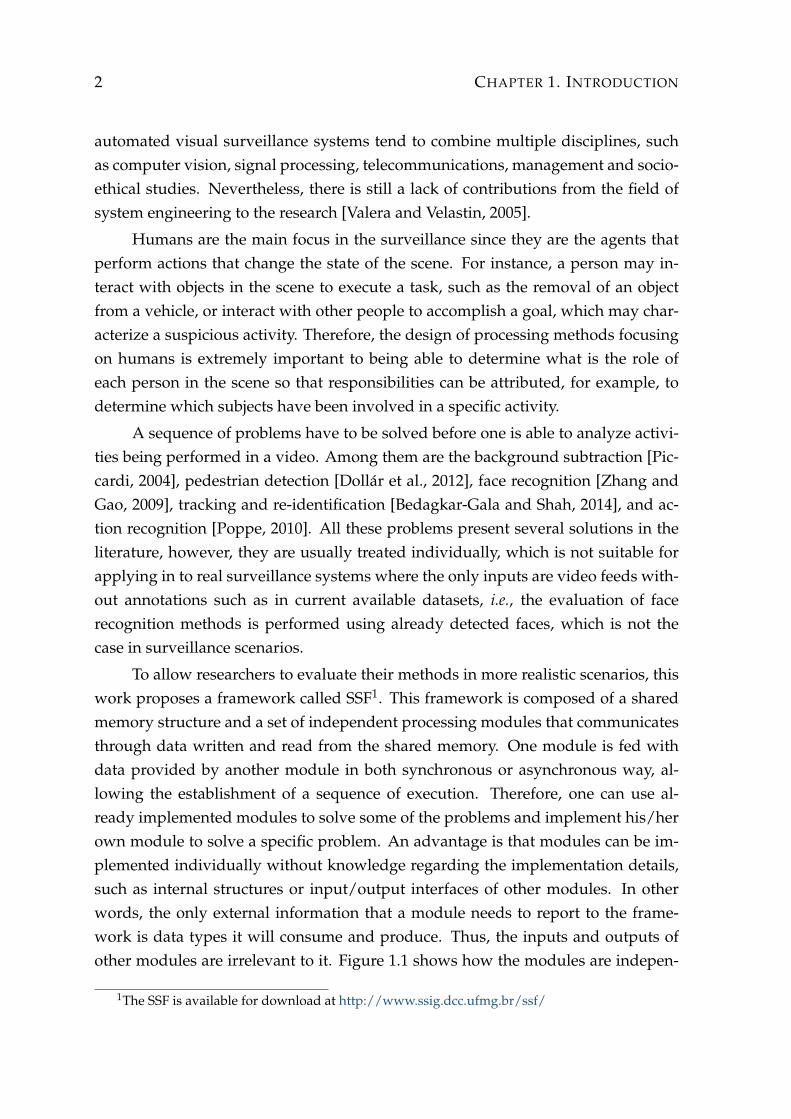
To allow researchers to evaluate their methods in more realistic scenarios, thiswork proposes a framework called SSF1. This framework is composed of a sharedmemory structure and a set of independent processing modules that communicatesthrough data written and read from the shared memory. One module is fed withdata provided by another module in both synchronous or asynchronous way, al-lowing the establishment of a sequence of execution. Therefore, one can use al-ready implemented modules to solve some of the problems and implement his/herown module to solve a specific problem. An advantage is that modules can be im-plemented individually without knowledge regarding the implementation details,such as internal structures or input/output interfaces of other modules. In otherwords, the only external information that a module needs to report to the frame-work is data types it will consume and produce. Thus, the inputs and outputs ofother modules are irrelevant to it. Figure 1.1 shows how the modules are indepen-
1The SSF is available for download at http://www.ssig.dcc.ufmg.br/ssf/
1.1. MOTIVATION 3
dent of each other. The details of framework will be discussed in the next chapters.
Inp
ut
A
Inp
ut
B
Inp
ut
B
Inp
ut
A
Ou
tpu
t A
Ou
tpu
t B
Ou
tpu
t A
Ou
tpu
t B
Ou
tpu
t B
Ou
tpu
t C
Ou
tpu
t A
Inp
ut
A
Shared Memory
Module 01 Module 03Module 02
Figure 1.1: The modules must know only their inputs and outputs since there isno direct communication between modules, but only through the shared memory,which makes the framework more flexible.
1.1 Motivation
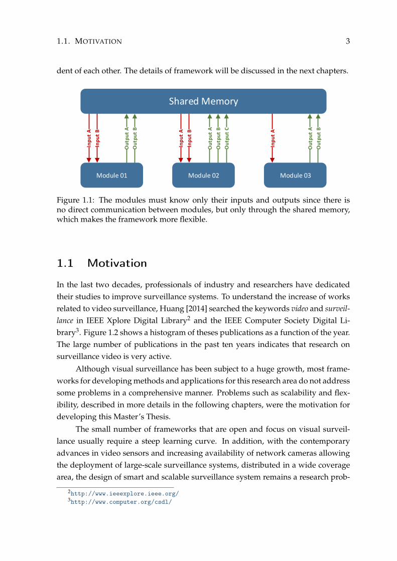
In the last two decades, professionals of industry and researchers have dedicatedtheir studies to improve surveillance systems. To understand the increase of worksrelated to video surveillance, Huang [2014] searched the keywords video and surveil-lance in IEEE Xplore Digital Library2 and the IEEE Computer Society Digital Li-brary3. Figure 1.2 shows a histogram of theses publications as a function of the year.The large number of publications in the past ten years indicates that research onsurveillance video is very active.
Although visual surveillance has been subject to a huge growth, most frame-works for developing methods and applications for this research area do not addresssome problems in a comprehensive manner. Problems such as scalability and flex-ibility, described in more details in the following chapters, were the motivation fordeveloping this Master’s Thesis.
The small number of frameworks that are open and focus on visual surveil-lance usually require a steep learning curve. In addition, with the contemporaryadvances in video sensors and increasing availability of network cameras allowingthe deployment of large-scale surveillance systems, distributed in a wide coveragearea, the design of smart and scalable surveillance system remains a research prob-
2http://www.ieeexplore.ieee.org/3http://www.computer.org/csdl/

4 CHAPTER 1. INTRODUCTION
0
200
400
600
800
1000
1200
1400
19
90
19
91
19
92
19
93
19
94
19
95
19
96
19
97
19
98
19
99
20
00
20
01
20
02
20
03
20
04
20
05
20
06
20
07
20
08
20
09
20
10
20
11
20
12
20
13
Nu
mb
er
of
Pu
blic
atio
ns
Year
IEEE Xplore DigitalLibrary
IEEE Computer SocietyDigital Library
Figure 1.2: Histogram of publications in IEEE Computer Society Library and IEEEXplore Digital Library whose metadata contains the keywords video and surveillance(Adapted from [Huang, 2014]).
lem: how to design scalable video surveillance systems considering aspects relatedto processing power, memory consumption and network bandwidth?
In general, when the researchers work with high-level problems, they haveto deal with a sequence of problems. These researchers present several solutionsin the literature, but in general, they treat the problems individually. Hence, tofind the best composition of such problems, they need to spend time working withthese applications first, instead of working directly with their application of inter-est. For instance, before approaching the individual action recognition problem, theresearcher usually have to perform pedestrian detection to locate each pedestrianin the image and, only after that, the approach for action recognition may be em-ployed. Therefore, dealing with the problems individually does not allow to findout what are the effects of the processing on the following steps.
It is desirable to employ an automatic mechanism to test various system com-ponents and to enable the comparison with other methods already developed. Sucha mechanism is very important to the research community since it will facilitatecomparison and validation of algorithms usually employed in visual surveillanceapplications.
Considering the aforementioned aspects, this Master’s Thesis was developedwith the objectives listed in the next section.
1.2. DISSERTATION’S GOAL 5
1.2 Dissertation’s Goal
This work proposes a framework for a scalable video analysis able to readily inte-grate different computer vision algorithms into a functional surveillance system ofthird generation (the third generation of surveillance systems is presented in Sec-tion 2.2.1).
The Smart Surveillance Framework (SSF) aims to bring several improvementsproviding scalability and flexibility, allowing the users to focus only on their appli-cation by treating the sequence of problems as a module set which communicatesthrough a shared memory.
The framework will also be an important tool for the research community,since it makes easier to compare and evaluate algorithms used in visual surveillanceapplications.
1.3 Contributions
The main contributions provided by the development of the SSF are the following:
• A novel framework to allow the processing of large amounts of data providedby multiple surveillance network cameras;
• A platform to compare and exchange research results in which researchers cancontribute with modules to solve specific problems;
• A framework to allow fast development of new video analysis techniquessince one can focus only on his/her specific task;
• Creation of a high-level semantic representation of the scene using data ex-tracted by low-level modules to allow the execution of activity recognition;
• A testbed to allow further development on activity understanding since onecan focus directly on using real data, instead of annotated data that may pre-vent the method from working on real environments;
• A scheme to allow scalable feature extraction that uses the full power of multi-core architectures;
Another important contribution is a review of published papers in recent yearsthat discuss the issues and challenges involved in the deployment of modern visual
6 CHAPTER 1. INTRODUCTION
surveillance systems, as well the discussion of similar works to the proposed frame-work.
Finally, the SSF may also contribute to improve teaching and learning activi-ties related to computer vision and image processing, for instance in introductorycourses, because the modularization of problems enables the identification and char-acterization of the steps involved in diverse application domains, which help in-structors and students in keeping their focus on specific subjects.
During the development of this work, we have produced two technical paperswhich have been submitted for publication. The following list provides referencesto these documents.
• Published: Nazare, A. C., Santos, C. E., Ferreira, R., and Schwartz, W. (2014).Smart surveillance framework: A versatile tool for video analysis. In IEEE WinterConference on Applications of Computer Vision (WACV 2014).
• Accepted: Nazare, A. C., Ferreira, R., and Schwartz, W. (2014). Scalable Fea-ture Extraction for Visual Surveillance. In Iberoamerican Congress on PatternRecognition (CIARP 2014).
In addition to these publications, a tutorial on the SSF will be presented duringthe Conference on Graphics, Pattern and Images (SIBGRAPI 2014). The acceptanceof this tutorial also resulted in an invitation for publication of a survey on Revistade Informática Teórica e Aplicada (RITA).
1.4 Dissertation Organization
This dissertation is organized into the following chapters. Chapter 2 reviews thepublished papers in the past years about the issues and challenges on visual surveil-lance systems. Chapter 3 describes the proposed Smart Surveillance Framework(SSF). Chapter 4 presents our experimental evaluation. Finally, Chapter 5 pointsour final remarks.
Chapter 2
Related Works
Several works related to video surveillance have been proposed in the past years.In this chapter, we review mainly works that focus on developing of visual surveil-lance applications. First, Section 2.1 presents the most common problems tackledin visual surveillance, as well as the relationship among these problems. In Sec-tion 2.1, is also focus to feature extraction problem, which is approached by one ofthe tools provided by the proposed framework, the Feature Extraction Server (FES),discussed in Section 3.3. Then, Section 2.2 presents a review of published papersin recent years that discuss the issues and challenges involved in the deploymentof modern visual surveillance systems and discusses works similar to the proposedframework.
2.1 Visual Surveillance
Since interactions among humans provide relevant information for activity under-standing, the analysis of images and videos involving humans (application domainknown as Looking at People (LAP) [Gavrila, 1999]) presents large interest of theresearch community, being widely employed to applications such as visual surveil-lance, biometrics and forensics. In this scope, solving computer vision problemssuch as feature extraction [Li and Allinson, 2008], background subtraction [Pic-cardi, 2004], pedestrian detection [Dollár et al., 2012], face recognition [Zhang andGao, 2009], person tracking [Yilmaz et al., 2006], person re-identification [Bedagkar-Gala and Shah, 2014], gesture recognition [Mitra and Acharya, 2007], pose estima-tion [Poppe, 2007], action recognition [Poppe, 2010], and activity recognition [Ag-garwal and Ryoo, 2011] is fundamental to model interactions among agents to un-derstand high-level activities performed in a scene under surveillance.
7
8 CHAPTER 2. RELATED WORKS
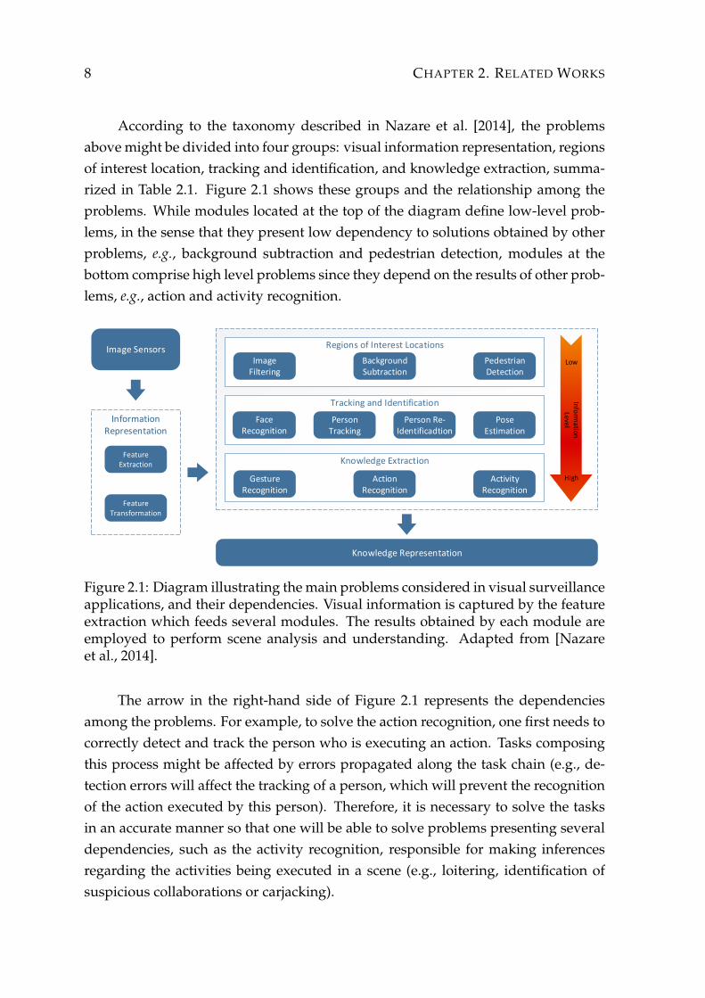
According to the taxonomy described in Nazare et al. [2014], the problemsabove might be divided into four groups: visual information representation, regionsof interest location, tracking and identification, and knowledge extraction, summa-rized in Table 2.1. Figure 2.1 shows these groups and the relationship among theproblems. While modules located at the top of the diagram define low-level prob-lems, in the sense that they present low dependency to solutions obtained by otherproblems, e.g., background subtraction and pedestrian detection, modules at thebottom comprise high level problems since they depend on the results of other prob-lems, e.g., action and activity recognition.
Image Sensors
Information Representation
Feature Transformation
Feature Extraction
Knowledge Representation
Regions of Interest Locations
Image Filtering
Background Subtraction
Pedestrian Detection
Tracking and Identification
Face Recognition
Person Tracking
Person Re-Identificadtion
PoseEstimation
Knowledge Extraction
Gesture Recognition
Action Recognition
Activity Recognition
Low
High
Info
rma
tion
Level
Figure 2.1: Diagram illustrating the main problems considered in visual surveillanceapplications, and their dependencies. Visual information is captured by the featureextraction which feeds several modules. The results obtained by each module areemployed to perform scene analysis and understanding. Adapted from [Nazareet al., 2014].
The arrow in the right-hand side of Figure 2.1 represents the dependenciesamong the problems. For example, to solve the action recognition, one first needs tocorrectly detect and track the person who is executing an action. Tasks composingthis process might be affected by errors propagated along the task chain (e.g., de-tection errors will affect the tracking of a person, which will prevent the recognitionof the action executed by this person). Therefore, it is necessary to solve the tasksin an accurate manner so that one will be able to solve problems presenting severaldependencies, such as the activity recognition, responsible for making inferencesregarding the activities being executed in a scene (e.g., loitering, identification ofsuspicious collaborations or carjacking).

2.1. VISUAL SURVEILLANCE 9
Visual Information Representation comprehends tasks aiming at representing theinformation contained in the visual data, e.g., converting pixel information to a fea-ture space which is more robust to noise and transformations taking place in thevideo. The main tasks related to this category are feature extraction and featurespace transformation. Even though it is not shown in the diagram of Figure 2.1, tomaintain the readability, the majority of the tasks depends on the feature extraction.
The goal of the Regions of Interest Location is to narrow down efficiently thelocations of the scene where information regarding activities taking place can beextracted. A motivation for locating regions of interest is to reduce the computa-tional cost and therefore to focus the processing power on the higher level process-ing tasks. Among the tasks in this category are image filtering (salience detection),background subtraction and pedestrian detection.
Once the tasks in the previous category have located the relevant regions in thescene for each frame, the problems in the Tracking and Identification category will es-timate their trajectories and identify the agents based on information including theirappearance or their faces. Such information will be necessary later for recognizingwhich actions an agent has performed over the time, for instance.
The last category, referred to as Knowledge Extraction, deals with problems re-sponsible for extracting high level knowledge from the scene. Therefore, once theobjects and agents have been located, identified and their trajectories have been es-timated, their actions will be recognized so that collaborations among agents char-acterizing suspicious activities can be recognized.
Besides the aforementioned categories, the Knowledge Representation is an im-portant component in a surveillance system. It is responsible for building a scenerepresentation based on the results of each problem so that one can use such infor-mation to make inferences and perform scene analysis.
The final stages in a surveillance system are storage and retrieval. In the pastyears, many research has been done in how to store and retrieve all the obtainedsurveillance information in an efficient manner, especially when it is possible tohave different data formats and types of information to retrieve [Valera and Velastin,2005]. Among them, we can cite the works published in [Hampapur et al., 2007;Choe et al., 2013].
The framework developed in this work has been designed to allow researchersto tackle with the problems shown in Figure 2.1 in such a way that the resultsachieved by solving these problems feed an inference system and the knowledgecan be used to understand the scene and the activities performed by the agents(persons).
10 CHAPTER 2. RELATED WORKS
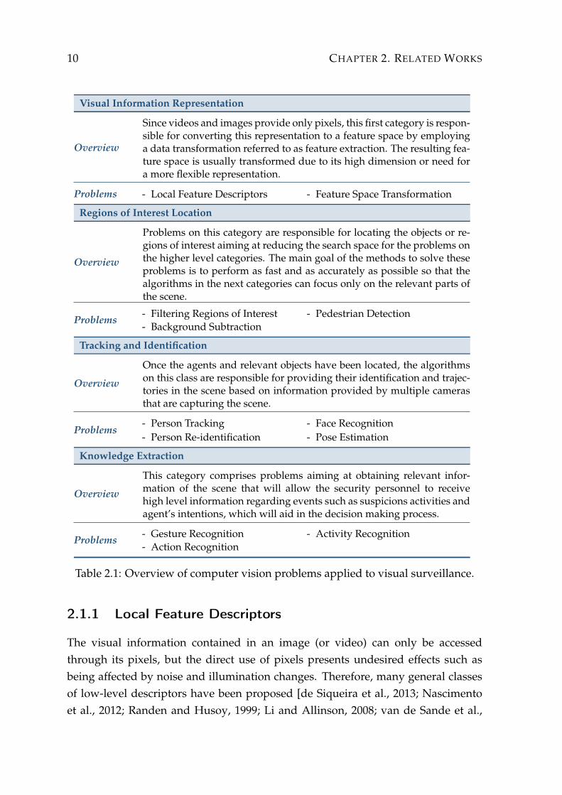
Visual Information Representation
Overview
Since videos and images provide only pixels, this first category is respon-sible for converting this representation to a feature space by employinga data transformation referred to as feature extraction. The resulting fea-ture space is usually transformed due to its high dimension or need fora more flexible representation.
Problems - Local Feature Descriptors - Feature Space Transformation
Regions of Interest Location
Overview
Problems on this category are responsible for locating the objects or re-gions of interest aiming at reducing the search space for the problems onthe higher level categories. The main goal of the methods to solve theseproblems is to perform as fast and as accurately as possible so that thealgorithms in the next categories can focus only on the relevant parts ofthe scene.
Problems - Filtering Regions of Interest- Background Subtraction
- Pedestrian Detection
Tracking and Identification
Overview
Once the agents and relevant objects have been located, the algorithmson this class are responsible for providing their identification and trajec-tories in the scene based on information provided by multiple camerasthat are capturing the scene.
Problems- Person Tracking- Person Re-identification
- Face Recognition- Pose Estimation
Knowledge Extraction
Overview
This category comprises problems aiming at obtaining relevant infor-mation of the scene that will allow the security personnel to receivehigh level information regarding events such as suspicions activities andagent’s intentions, which will aid in the decision making process.
Problems - Gesture Recognition- Action Recognition
- Activity Recognition
Table 2.1: Overview of computer vision problems applied to visual surveillance.
2.1.1 Local Feature Descriptors
The visual information contained in an image (or video) can only be accessedthrough its pixels, but the direct use of pixels presents undesired effects such asbeing affected by noise and illumination changes. Therefore, many general classesof low-level descriptors have been proposed [de Siqueira et al., 2013; Nascimentoet al., 2012; Randen and Husoy, 1999; Li and Allinson, 2008; van de Sande et al.,
2.1. VISUAL SURVEILLANCE 11
2010; Mikolajczyk and Schmid, 2005; Zhang et al., 2007; Gauglitz et al., 2011] focus-ing on different image characteristics, such as color, shape, and texture.
Local feature descriptors are used to describe local regions in the images. Twomain approaches are employed to sample these regions. The first is based on thedetection of interest points (discriminative points located usually in corners of ob-jects detected by feature detectors [Mikolajczyk and Schmid, 2005; Li and Allinson,2008]), and the sampling of regions around them. The second approach simplysamples local regions from the image in a uniform manner. Even though the latterapproach generates more data, it tends to miss information from regions that cannotbe captured by the feature detector. At the end, each local regions will be describedby a feature vector according to the extraction method being employed.
Feature extraction is critical for surveillance systems since several algorithmsrequire feature descriptors as input. However, most feature extraction algorithmsare highly time consuming and not suitable for real time applications. Researchershave also devoted their studies to optimize the feature extraction methods. One ofthe early works was proposed by Viola and Jones [2001], the integral image, an in-termediate representation that allows faster computation of rectangle features. Dol-lar et al. [2009] proposed linear and non-linear transformations to compute multi-ple registered image channels, called Integral Channel Feature. Authors employedthese descriptors into their CHNFTRS detector achieving state-of-the-art results inpedestrian detection. Based on their previous work on Integral Channel Feature,Dollar et al. [2010] proposed a feature extraction method that exploits the inter-polation of features in different image scales, significantly reducing the cost andproducing faster detectors when coupled with cascade classifiers. Recently, Marinet al. [2013] proposed the use of Random Forests to combine multiple local experts.To reduce computational cost, the multiple local experts share the extracted fea-tures. Another approach is the use of parallel architectures, as multi-core proces-sors and General Purpose Graphics Processing Unit (GPGPU), for feature extraction.For instance, Prisacariu and Reid [2009] showed in their work efficient ways to ex-tract Histogram of Oriented Gradients (HOG) descriptors using GPGPU, achievedspeedups of over 67× from the standard sequential code.
Among the several known feature descriptors, we can mention few relevantmethods. a) Scale Invariant Feature Transformation (SIFT) [Lowe, 2004] - a localimage region is divided into a grid (e.g.; 4 × 4 pixels and a gradient orientationhistogram is computed for each cell of the grid; b) Histogram of Oriented Gradi-ents (HOG) [Dalal and Triggs, 2005] - a histogram of location and orientation ofimage gradients is constructed and used as feature vector (see details on Figure 2.2);

12 CHAPTER 2. RELATED WORKS
c) Gray-Level Co-occurrence Matrix (GLCM) [Haralick et al., 1973] - the occurrenceof pairs of pixel intensities is tabulated in a matrix, from which statistical measuresare computed and used as feature descriptors. The last two feature descriptors willbe considered in our experiments to evaluate the proposed framework.
Block
Orientation HistogramCell
Figure 2.2: Illustration of HOG computation.
To address the feature extraction problem, the SSF provides a powerful tool:the Feature Extraction Server (FES), which allows the feature extraction to be per-formed using the entire computational power available in the system to maximizethe performance (one can use all available CPU cores) and also allows researchersto use feature descriptors implemented by third parties. The Feature ExtractionServer (FES) is detailed in Section 3.3.
2.2 Surveillance Systems
Nowadays, there is an increasing interest in surveillance applications because of theavailability of low-cost sensors and processors. There is also an emerging need fromthe public for improving safety and security in urban environments and the signif-icant utilization of resources in public infrastructure. These two factors associatedwith the growing maturity of algorithms and techniques, enable the application oftechnology in public, military and commercial sectors [Regazzoni et al., 2001].
Smart visual surveillance systems deal with the real-time monitoring of objectswithin an environment. The main goal of these systems is to provide an automaticinterpretation of scenes and to understand and predict the actions and interactionsof the observed objects based on the information acquired by video cameras.
Current research in automated visual surveillance systems tends to com-bine multiple disciplines such as those mentioned earlier with signal processing,telecommunications, management and socio-ethical studies. Nevertheless there is

2.2. SURVEILLANCE SYSTEMS 13
be lack of contribution from the field of system engineering to the research [Valeraand Velastin, 2005].
The next sections will overview the state of art in Smart Visual SurveillanceSystems, introducing the evolution of these systems, as well as their applications,requirements and challenges.
2.2.1 Evolution of Surveillance Systems
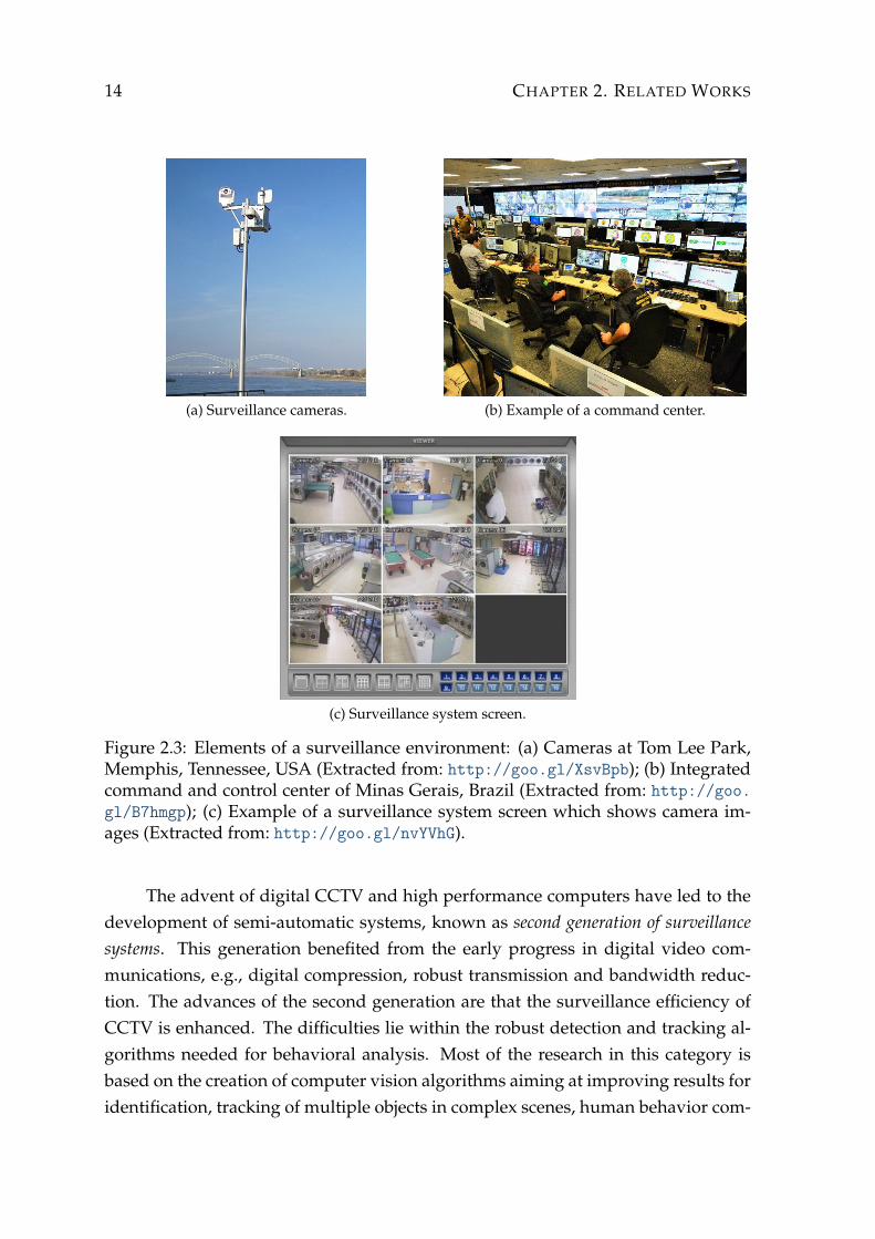
Security surveillance systems are becoming crucial in situations in which personalsafety could be compromised resulting from criminal activity. For this, video cam-eras are constantly being installed for security reasons in prisons, parks, banks, au-tomatic teller machines, gas stations, and elevators, which are the most susceptiblefor criminal activities [Räty, 2010]. For instance, Figure 2.3a shows a set of camerasplaced at Tom Lee Park, Memphis, Tennessee, USA.
In general, images provide by a set of cameras may be monitored in real time atthe command center (Figure 2.3b), where exists many display screens from which se-curity personnel constantly monitors suspicious activities (Figure 2.3c). Images canalso be archived for investigative purposes. However, the entire burden of watch-ing video, detecting threats, and locating suspects are assigned to the human oper-ator. This process of manually watching video is known to be tedious, ineffective,and expensive [Hampapur, 2008], because the attention span of human observersis inevitably limited [Davies and Velastin, 2007]. Therefore, the addition of compu-tational intelligence to alert the observers to the infrequent image feed which con-tained events of possible importance was thus a natural development as computingresources became both cheaper and more powerful.
According to Valera and Velastin [2005] and Räty [2010], the technological evo-lution of surveillance systems can be divided into three generations, which are sum-marized in Table 2.2.
The first generation of surveillance systems started with analogue CCTV (Closed-Circuit Television). These systems consist of a number of cameras placed in multiplelocations and connected to a set of monitors, usually placed in a single control room,via switches (a video matrix). The main disadvantages of these systems concern thereasonably small attention span of operators that may result in a significant missrate of the events of interest. The advantage is that they provide good performancein some cases and the technology is mature. To perform computational processingon this type of system conversion from analog to digital video is required whichmay cause quality degradation.
14 CHAPTER 2. RELATED WORKS
(a) Surveillance cameras. (b) Example of a command center.
(c) Surveillance system screen.
Figure 2.3: Elements of a surveillance environment: (a) Cameras at Tom Lee Park,Memphis, Tennessee, USA (Extracted from: http://goo.gl/XsvBpb); (b) Integratedcommand and control center of Minas Gerais, Brazil (Extracted from: http://goo.gl/B7hmgp); (c) Example of a surveillance system screen which shows camera im-ages (Extracted from: http://goo.gl/nvYVhG).
The advent of digital CCTV and high performance computers have led to thedevelopment of semi-automatic systems, known as second generation of surveillancesystems. This generation benefited from the early progress in digital video com-munications, e.g., digital compression, robust transmission and bandwidth reduc-tion. The advances of the second generation are that the surveillance efficiency ofCCTV is enhanced. The difficulties lie within the robust detection and tracking al-gorithms needed for behavioral analysis. Most of the research in this category isbased on the creation of computer vision algorithms aiming at improving results foridentification, tracking of multiple objects in complex scenes, human behavior com-

2.2. SURVEILLANCE SYSTEMS 15
First Generation
Techniques - Analogue Closed-Circuit Television (CCTV) systems
Coverage - Small/Medium areas (i.e. shop, banks, schools)
Smart - No
Data processing - None
Advantages - Good performance in some situations and mature technology
Problems - Use analogue techniques
Research - Digital versus analogue- CCTV video compression
Second Generation
Techniques - Automated by combining computer vision with CCTV systems
Coverage - Small/Medium areas (i.e. shop, banks, schools)
Smart - Yes
Data processing - Low
Advantages - Increase the surveillance efficiency of CCTV systems
Problems - Robust algorithms required for behavioral analysis
Research - Automatic learning of scene variability and patterns of behaviors
Third Generation
Techniques - Automated wide-area surveillance system
Coverage - Large areas (i.e. cities, highways)
Smart - Yes
Data processing - High
Advantages - More accurate information and distribution of different sensors type
Problems - Distribution of information (integration and communication)- Moving platforms, multi-sensor platforms
Research - Distributed versus centralized intelligence- Data fusion and multi-camera surveillance techniques
Table 2.2: Summary of technical evolution of intelligent surveillance systems.(Adapted from [Valera and Velastin, 2005]).

16 CHAPTER 2. RELATED WORKS
prehension, and multi-sensor data fusion. The second generation also improvedintelligent human-machine interfaces, performance evaluation of video processingalgorithms, signal processing for video compression and multimedia transmissionfor video-based surveillance systems [Räty, 2010].
In the third generation, the technology revolves around wide-area surveillancesystems, dealing with a large number of cameras, geographically distributed re-sources and several monitoring points. Such factors allowed the acquisition of moreaccurate information by combining different types of sensors and the distributionof the information. The difficulties are in achieving efficient information integrationand communication, the establishment of design methodologies, and the task of de-signing and deploying multi-sensor platforms. The current research concentrates ondistributed and centralized intelligence, data fusion, probabilistic reasoning frame-works, and multi-camera surveillance techniques [Valera and Velastin, 2005]. Ac-cording to Räty [2010] the main objective of the fully third generation system is toease efficient data communication, management, and extraction of events in real-time video from a large collection of sensors. To achieve this goal, improvementsin automatic recognition functionalities and digital multiuser communications arerequired.
2.2.2 General Surveillance Systems
Several surveillance systems of the third generation have been designed and devel-oped both in the industry and in the academia. These systems can be classified intotwo groups: general purpose and specialized in a certain function. Most works inthe literature describe systems in the latter group ()discussed in Section 2.2.3).
Different from the specialized systems, the SSF can be classified as generalpurpose because the user (researcher) has the freedom to develop his/her modules(as described in Section 3.6) and use them for any purpose involving surveillance.The following paragraphs present examples of known general-purpose systems andtheir similarities and differences with the framework proposed in this work.
Several technologies for video-based surveillance have been developed undera United States government funded program called Video Surveillance and Mon-itoring (VSAM) [Collins et al., 2000]. This program, which can be considered oneof the pioneers among the third-generation systems, looked at several fundamentalissues in detection, tracking, auto-calibration, and multi-camera systems. The goalof VSAM was to develop efficient wide-area video surveillance systems using a dis-tributed network of cameras. The system provided the capability to detect, track, lo-
2.2. SURVEILLANCE SYSTEMS 17
calize and visualize objects within the known environment. Similar to other newersystems, the SSF incorporates several concepts based on VSAM, such as scalability,modularization and code reuse.
Knight [Shah et al., 2007] is a fully automated system with multiple surveil-lance cameras that detects, categorizes and tracks moving objects in the scene usingcomputer vision techniques. Although it can be used in various types of surveillanceenvironments, the Knight is a closed framework that does not allow the implemen-tation of new methods to replace or extend to the existing ones. In addition, it is acommercial system, hindering its use in academia.
Another system is the IBM Smart Surveillance System (S3) [Tian et al., 2008],which is among the most advanced surveillance systems nowadays. It providesthe following capabilities: automatic monitoring of a scene, management of surveil-lance data, perform event based retrieval and receive real-time event alerts. In S3,computer vision routines are not implemented directly into the system, but as plu-gins. One of its disadvantages it that it requires the use of technologies from IBM,such as IBM DB2 and IBM WebSphere, which reduces its applicability for researchpurposes.
San Miguel et al. [2008] and Suvonvorn [2008] proposed two general-purposeframeworks for processing and analyzing surveillance videos. Similarly to the SSF,they enable the development of modules for processing images and videos. How-ever, they have adopted a different approach for data communication between themodules. In [San Miguel et al., 2008], the communication between modules ismapped through a database system, while in [Suvonvorn, 2008], the modules com-municate directly, where a buffer is used as an exchange zone. In contrast, modulesin the SSF do not communicate directly, but through a shared memory, which allowsmodules to be launched in an asynchronous way and the dependency among themcan be defined as parameters, making the SSF versatile and flexible.
Xie et al. [2002] proposed a Software Infrastructure for Smart Space (SISS),called Smart Platform. A smart space is a typical multi-modal system which typ-ically involved dozens of distributed computation and perception modules that areusually not developed for running together, such as speech recognition, person-tracking and gesture recognition. The Smart Platform is a flexible and extensiblecross-platform system that allows modules to be restarted or moved to differenthosts and system reconfigurations in execution time. It was designed for pervasivecomputing, so it does not meet some requirements of video surveillance analysis,such as lack of mechanisms to facilitate the representation of object tracking, actionsand activities.

18 CHAPTER 2. RELATED WORKS
The work proposed by Afrah et al. [2009] addresses two aspects in the devel-opment of vision-based systems that are not fully exploited in many current frame-works: abstraction above low-level details and high-level module reusability. Theyproposed a systematic classification of subtasks in vision-based system develop-ment. However, this framework is inflexible in according to the exchange of mod-ules, preventing researchers from comparing results obtained by different methods,which would be an important feature for the academic community.
With a proposal similar to the SSF, the work proposed by Wang et al. [2012]presents a vision system architecture that can readily integrate computer vision pro-cessing and make application modules share services and exchange messages trans-parently. The model of computation assumed by the authors is the same used inthe SSF. In this model, modules communicate with each other through a sharedmemory and are executed independently and in parallel.
Despite their similarities, there are some key difference between the two ap-proaches: a) Wang et al. [2012] system, the processing is centralized for some tasks,such as capturing sensor data, encoding and decoding video streams, and trans-forming different types of data, but on the SSF all processing is performed in par-allel on modules, which allows a better use of the processing power; b) the sharedmemory on the SSF stores the scene information in a hierarchy based on the nec-essary structures for surveillance environment to avoid data redundancy, allowinglow memory consumption (for more details, see Section 3.2); c) the SSF allows oneto perform complex queries on data in shared memory through the Complex QueryServer (CQS) (Section 3.4).
Another aspect that differentiates SSF from other systems is that SSF imple-ments the Feature Extraction Server (FES), described in Section 3.3, which allowsthe feature extraction to be performed using the entire computational power avail-able in the system with the objective of maximizing the performance (one can use allavailable CPU cores). In the other systems mentioned earlier, the feature extractionprocess receives no special treatment, being under the user‘s responsibility.
2.2.3 Applications
To design efficient systems, it is necessary that researchers understand the natureof the environments in which the systems will be used. Another issue is to be ableto interpret the requirements of the end user. Regazzoni et al. [2001]; Valera andVelastin [2005]; Sedky et al. [2005]; Hampapur et al. [2003] classified real-world ap-plications into the following monitoring categories:
2.2. SURVEILLANCE SYSTEMS 19
Public AreaDetect anomalous behavior from a person or a group of people in subways,parking lots, stadiums, large facilities and other public areas;
Interior and Exterior of BuildingsImprove safety in buildings, such as banks, shopping malls and houses. Ac-cess control, intrusion detection, object removal/abandoned alert and peoplecounting are common surveillance tasks in this category.
TransportMonitoring for railway stations, airports and maritime environments, trafficmeasure, accident detection and autonomous navigations.
MilitarySurveillance of strategic infrastructure, enemies movements in the battlefieldsand air monitoring.
EntertainmentInteractive games interface, sport analysis, broadcast of abstract and sportsevents.
Efficiency ImprovementLong routine tasks, personalized training, coordination in workplace, compil-ing consumer demographics and monitor.
There are several published papers on surveillance applications. Among themwe can mention, the work of Xia et al. [2013] that focuses on wide-area traffic mon-itoring for highway roads. Odobez et al. [2012], in turn, designed a metro stationmonitoring system that aims at automatically detecting dangerous situations whichmay lead to accidents or violence. The system proposed by Thornton et al. [2011]allows an operator to search through large volumes of airport surveillance videodata to find persons that match a particular attribute profile. Siebel and Maybank[2004] especially deal with the problem of multi-camera tracking and person han-dover, on metro stations, within the ADVISOR surveillance system. A frameworkfor people searching, where the user can specify personal attributes through queriessuch as “Show me the bald people who entered a given building last Saturday wearinga red shirt”, was proposed by Vaquero et al. [2009]. It is important to notice that,many surveillance applications are of commercial license, and thus, there are nonescientific sources that describe them.

20 CHAPTER 2. RELATED WORKS
Being a general tool, the SSF enables the development of many types of appli-cations since coding specific modules to address many visual surveillance problemsallows the user to develop various applications types. In addition, the exchange/-combination of these modules can generate new applications. Appendix A illus-trates an example of real application developed using the SSF.
2.2.4 Challenges
As mentioned earlier, surveillance systems of the third generation contribute sig-nificantly to the design of various types of secure environments. Meanwhile, alongwith improvements, several challenges have emerged, causing many researchersdevote their studies to do so. The work published by Liu et al. [2009] discussessome challenging issues faced by researchers. Other papers addressing the chal-lenges of smart surveillance systems have been published recently, such as Räty[2010]; Haering et al. [2008]; Hampapur et al. [2003]; Regazzoni et al. [2001]. Thenext paragraphs present an overview on these challenges.
Quality and Consistency of Data Image
Images are not always perfect in such systems. For instance, objects of interest canbe partially occluded, camera lenses maybe covered or damaged, the person beingidentified may have covered himself/herself by purpose. Even when these prob-lems do not exist, there are other aspects causing decreasing the image quality, suchas, poor illumination, sensor noise, particularly in poor lighting conditions and lowresolution of the cameras.
The detection of events related to certain individuals comes from differentcameras when the individuals are moving, for instance in an airport. Therefore,events detected from multiple cameras/sensors relating to the same object (person-/people) must be combined to reduce uncertainty and inconsistency. A typical sce-nario is that from a camera with poor visibility a male is detected while from theaudio recording it strongly indicates a female. So adequate methods must be ap-plied to resolve this inconsistency.
This type of challenge comprises several sub-challenges in computer vision.Since they are out of the focus of this work, these problems will not be detailed.Please, see [Liu et al., 2013; Valera and Velastin, 2005; Räty, 2010] for further reading.

2.2. SURVEILLANCE SYSTEMS 21
Flexibility and Scalability
A large-scale video surveillance system comprises many video sources distributedover a large area, transmitting live video streams to a central location for monitor-ing and processing. Contemporary advances in video sensors and the increasingavailability of networked digital cameras have allowed the deployment of large-scale surveillance systems over existing network infrastructure. However, design-ing a smart and scalable surveillance system remains a research problem: how todesign scalable video surveillance systems according to aspects related to process-ing power, memory consumption and network bandwidth?
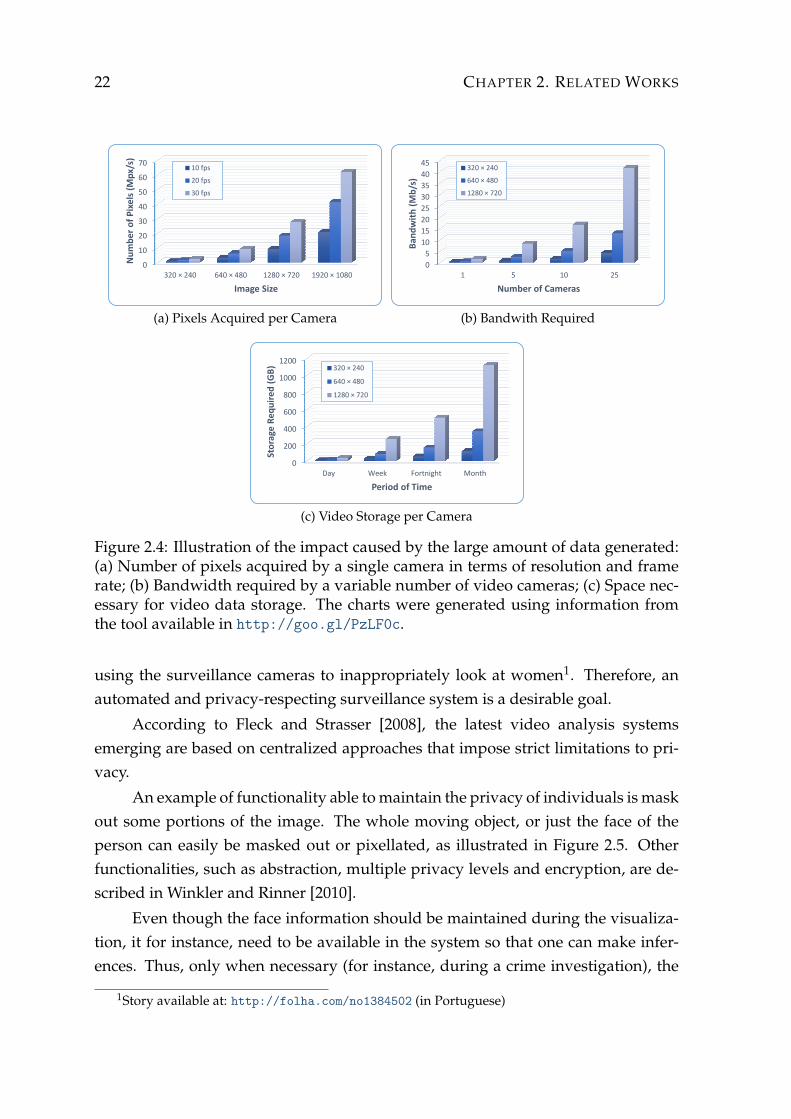
Besides the wide availability of cameras, the emergence of high-resolution im-age sensors at higher frame rates (Frames per Second (FPS)) contribute to the in-crease of the amount of generated data. From the charts in Figure 2.4, it can beconcluded that the quality of images generated by a camera is directly proportionalto the computational power needed to process them. This is a problem for surveil-lance systems: being able to process data in real time. Thus, novel solutions areneeded to handle restrictions of video surveillance systems, both in terms of com-munication bandwidth and computing power. A solution to decrease the necessarybandwidth is to allocate machines, responsible for processing, close to the sensors.
The framework proposed in this work deals with the scalability problemthrough the implementation of modules (see Section 3.6) which are executed in par-allel. Thus, the researcher can partition his/her problem into smaller problems andexecute them as a pipeline. Another feature that contributes to the performance isthe FES, detailed in Section 3.3.
Privacy
According to Fleck and Strasser [2010], the privacy is a fundamental and very per-sonal property to be respected so that each individual can maintain control of theflow of information about himself/herself. According to Gilbert [2007], privacycomprises confidentiality, anonymity, self-determination, freedom of expression,and control of personal data.
In the surveillance environment, it is important to guarantee privacy, as per-sons within a perimeter covered by cameras have very little choice of being filmedor not, whereas e.g., in the case of cell phone tracking the user still has the choiceto turn his phone off. Additionally, it is not always apparent where cameras are lo-cated. Another problem is that operators are not always well-intentioned, such asrecently happened on Araraquara (São Paulo, Brazil) in which the operators were
22 CHAPTER 2. RELATED WORKS
0
10
20
30
40
50
60
70
320 × 240 640 × 480 1280 × 720 1920 × 1080
Nu
mb
er
of
Pix
els
(M
px/
s)
Image Size
10 fps
20 fps
30 fps
(a) Pixels Acquired per Camera
0
5
10
15
20
25
30
35
40
45
1 5 10 25
Ban
dw
ith
(M
b/s
)
Number of Cameras
320 × 240
640 × 480
1280 × 720
(b) Bandwith Required
0
200
400
600
800
1000
1200
Day Week Fortnight Month
Sto
rage
Re
qu
ire
d (
GB
)
Period of Time
320 × 240
640 × 480
1280 × 720
(c) Video Storage per Camera
Figure 2.4: Illustration of the impact caused by the large amount of data generated:(a) Number of pixels acquired by a single camera in terms of resolution and framerate; (b) Bandwidth required by a variable number of video cameras; (c) Space nec-essary for video data storage. The charts were generated using information fromthe tool available in http://goo.gl/PzLF0c.
using the surveillance cameras to inappropriately look at women1. Therefore, anautomated and privacy-respecting surveillance system is a desirable goal.
According to Fleck and Strasser [2008], the latest video analysis systemsemerging are based on centralized approaches that impose strict limitations to pri-vacy.
An example of functionality able to maintain the privacy of individuals is maskout some portions of the image. The whole moving object, or just the face of theperson can easily be masked out or pixellated, as illustrated in Figure 2.5. Otherfunctionalities, such as abstraction, multiple privacy levels and encryption, are de-scribed in Winkler and Rinner [2010].
Even though the face information should be maintained during the visualiza-tion, it for instance, need to be available in the system so that one can make infer-ences. Thus, only when necessary (for instance, during a crime investigation), the
1Story available at: http://folha.com/no1384502 (in Portuguese)

2.2. SURVEILLANCE SYSTEMS 23
faces may be viewed and only by authorized persons.
Figure 2.5: Masking out the face of a personal to address privacy concerns. (Extractfrom: http://goo.gl/maps/pdioc).
Besides of the papers which discuss the privacy of technical manner, there areseveral others that deal with the subject of a sociological point of view, as the workpublished in Posner [2008], where is discussed how surveillance systems must ad-dress some aspects of privacy, which are guaranteed by the law of the United States.
System Evaluation
Second Haering et al. [2008], one of the major challenges of developing a smartsurveillance system is that it has to operate robustly during the entire time in a inwide range of scenarios. The only way to ensure robust and reliable performance isto perform extensive testing.
The following questions are relevant for system evaluation. Is it possible toestablish a repository containing some common surveillance scenarios? Who are thepeople providing these scenarios, and what are the evaluations criteria? To answerthese questions, Venetianer and Deng [2010] discuss some of the major challengesinvolved and provides a case study for addressing the evaluation problem.
For algorithms in other areas, such as machine learning, there are standarddata sets to validate, evaluate and compare the algorithms. However, for visualsurveillance systems, each security concern is different, the objects being recognizedand events being detected are more specific according to the application. Therefore,it is a very difficult task to evaluate a complete surveillance system from a caseawareness viewpoint [Liu et al., 2009].
The performance evaluation of video analysis systems requires significantamount of annotated data. Typically, annotation is a very expensive and tedious

24 CHAPTER 2. RELATED WORKS
process. Additionally, there can be significant errors in annotations and part of theevaluation of the surveillance systems depends on what the system operator con-siders as relevant action since they are not objective. All of these issues make per-formance evaluation a significant challenge [Hampapur et al., 2003].
For the aforementioned reasons, it is desirable an automatic mechanism thatallows to test various system components and that facilitates comparison with ex-isting methods. With the proposed framework is possible to solve the comparisonof methods problem since it is very easy to change only the modules that perform aparticular function without having to recode the entire rest of the process. Thus, theresults generated by these modules may be fairly compared. The automated test forthe entire surveillance system with a given purpose can also be done in the SSF justby writing specialized modules for this task.
Chapter 3
Smart Surveillance Framework
The SSF is a C/C++ library built using the Open Source Computer Vision Library(OpenCV) and the C++ Standard Template Library (STL) to provide a set of func-tionalities to aid researchers not only on the development of surveillance systemsbut also on the creation of novel solutions for problems related to video surveil-lance, as those described in Section 2.1.
One of its main goals is to provide a set of data structures to describe the sceneallowing researches to focus only on their problems of interest and to use this in-formation without creating such infrastructure for every problem that will be tack-led, as it is done in the majority of cases nowadays. For instance, if a researcheris working on individual action recognition, he/she would need firstly to capturedata, detect and track people, and only then perform action recognition. By usingthe SSF, one just needs to launch the detection and tracking modules (that mighthave been implemented by somebody else), to provide the people’s location. In thiscase, one may concentrate only on the problem at hand, action recognition withoutconcerning with the design of data representation, storage and communication.
The framework was designed to provide features for a third generationsurveillance system [Räty, 2010; Valera and Velastin, 2005], such as tools to performscene understanding, scalability, real-time operation, multi-sensor environment, us-age of low-cost standard components, runtime re-configuration, and communica-tion control. The next sections describe the design choices of the SSF to providesuch desirable features.
25
26 CHAPTER 3. SMART SURVEILLANCE FRAMEWORK
3.1 Architecture
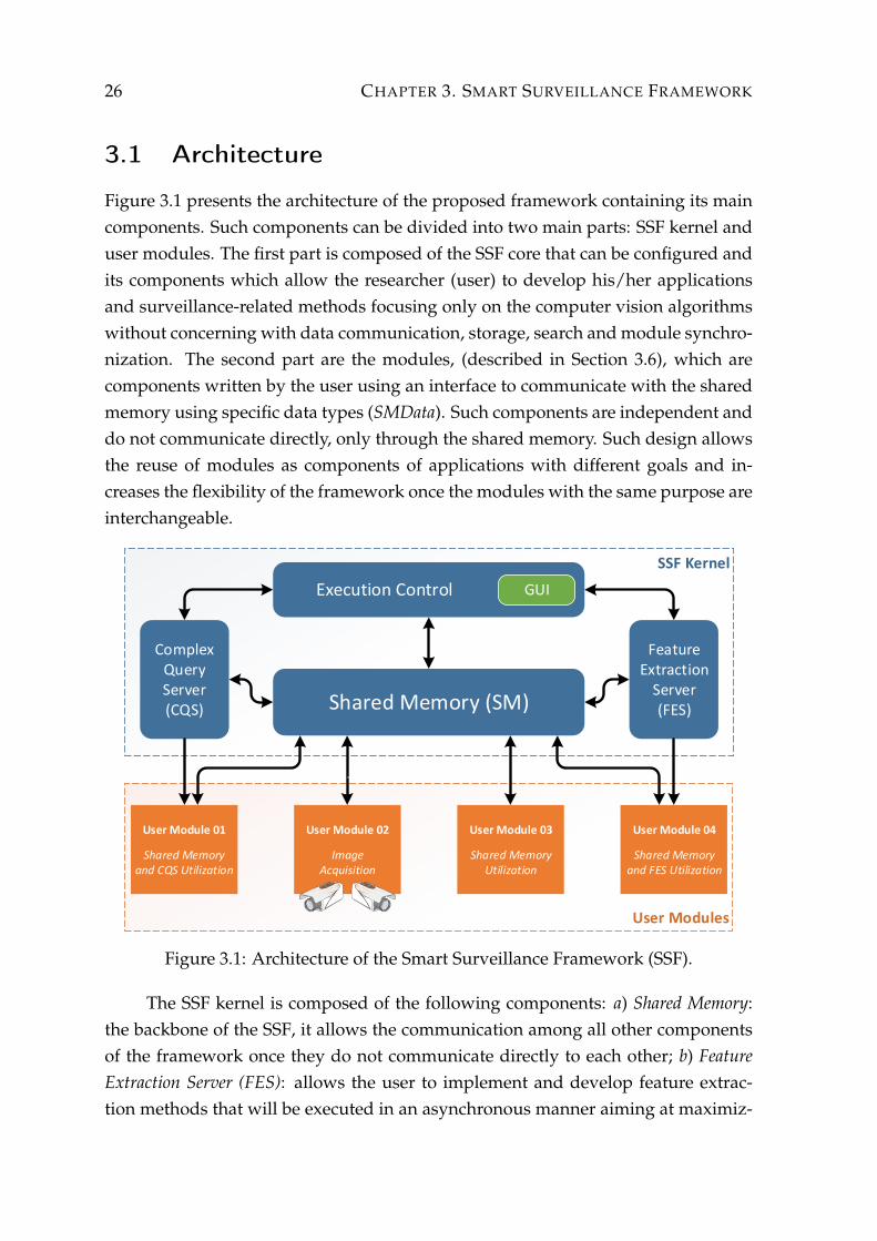
Figure 3.1 presents the architecture of the proposed framework containing its maincomponents. Such components can be divided into two main parts: SSF kernel anduser modules. The first part is composed of the SSF core that can be configured andits components which allow the researcher (user) to develop his/her applicationsand surveillance-related methods focusing only on the computer vision algorithmswithout concerning with data communication, storage, search and module synchro-nization. The second part are the modules, (described in Section 3.6), which arecomponents written by the user using an interface to communicate with the sharedmemory using specific data types (SMData). Such components are independent anddo not communicate directly, only through the shared memory. Such design allowsthe reuse of modules as components of applications with different goals and in-creases the flexibility of the framework once the modules with the same purpose areinterchangeable.
SSF Kernel
User Modules
User Module 01
Shared Memoryand CQS Utilization
Shared Memory (SM)
User Module 02
Image Acquisition
User Module 04
Shared Memoryand FES Utilization
User Module 03
Shared MemoryUtilization
Complex Query Server(CQS)
FeatureExtraction
Server(FES)
Execution Control GUI
Figure 3.1: Architecture of the Smart Surveillance Framework (SSF).
The SSF kernel is composed of the following components: a) Shared Memory:the backbone of the SSF, it allows the communication among all other componentsof the framework once they do not communicate directly to each other; b) FeatureExtraction Server (FES): allows the user to implement and develop feature extrac-tion methods that will be executed in an asynchronous manner aiming at maximiz-
3.2. SHARED MEMORY 27
ing the usage of the computational resources available in the system; c) ComplexQuery Server (CQS): this component allows modules to search for specific data inthe shared memory by taking advantage of Prolog, queries in SQL databases, amongothers; d) Execution Control: this component controls the execution of the modules,internal components of the SSF and is responsible for the SSF initialization. In ad-dition, this component has a graphical interface to aid the user to configure theruntime environment.
3.2 Shared Memory
To allow modules to be designed and implemented independently from each other,it is necessary preventing direct data transmission among them, otherwise, onemodules would need to be aware of other module interface, which would reducethe flexibility when integrating a set of modules to solve a given task. To addressthis constraint, the SSF provides a resource to store and control of the data com-munication between the user modules. This feature, referred to as shared memory,defines an interface to modules write and read data items.
The shared memory was designed to enable the development of many typesof applications, including applications that are not in the visual surveillance scope.For this proposed, it was composed of three components, as illustrated in Figure 3.2,described as follows.
The first component, called Memory Manager, is responsible for the storage andmanagement of the handled data. In the SSF, the data items are created by usermodules and their references are passed on to the shared memory and the MemoryManager becomes responsible for the management of these references.
Since surveillance systems must handle large volumes of data (see Sec-tion 2.2.4), the memory on the SSF host machine can be easily filled. Thus, to dealthis problem, the Memory Manager has a mechanism to detect when the primarymemory is almost full and store the oldest entries on a secondary storage device (i.e.a hard disk or a solid-state drive (SSD)), thus increasing the memory limit that canbe used by the SSF. In this way, when a data is required, the memory manager firstchecks whether it is in primary memory, otherwise it is retrieved from the secondarymemory.
The second component is the Basic Shared Memory, responsible for the func-tions to access the data. This component does not depend on the context of theapplication, that is, their interface functions are general (i.e., functions to write and

28 CHAPTER 3. SMART SURVEILLANCE FRAMEWORK
Shared Memory
Specialized Shared Memory
Basic Shared Memory
Memory Management
User ModuleM1
User ModuleM2
User ModuleM3
Figure 3.2: Components of the shared memory.
read data items) and have no knowledge of the data type being manipulated.
The third component, the Specialized Shared Memory, is a specialization of theshared memory, with surveillance purposes. This component provides methodsand specific data types for the surveillance domain and is available when the useris developing user modules.
Focusing on surveillance, the shared memory stores the scene information in ahierarchy to avoid data redundancy, as showed in Figure 3.3. All data structures arestored in lists and only their unique identifiers on the lists are stored in the elementsof the hierarchy, which not only avoids the need for updating the information everytime the data structures are changed, but also reduces the data redundancy.
Ob
ject
Trac
klet
Sam
ple
Trac
klet
Feed Frame
...
Figure 3.3: Hierarchical structure in the shared memory to store information regard-ing the scene under surveillance.

3.2. SHARED MEMORY 29
The following data structures and attributes are used in the shared memory torepresent the scene under surveillance:
Feed is a sequence of frames that may have been obtained from a video file, a set ofimage files or frames obtained from a surveillance camera.
Frame contains an image of the feed and the attributes associated to it. Its attributescontain feature descriptors extracted from the frame, masks provided by thebackground subtraction and filtering methods and samples with possible ob-ject locations in the frame.
Sample represents the region of a frame containing an object. Its attributes containfeature descriptors, reference to the frame, sample location and possibly thegesture and pose when the sample belongs to a person.
Tracklet contains a set of samples from consecutive frames belonging to a singleobject. Its attributes contain feature descriptors extracted from the tracklet(usually temporal features) and the actions performed by the person duringthe tracklet duration.
Object is defined as being a set of tracklets belonging to a single individual associ-ated with an identifier (for instance, the person’s name).
Besides the standard structures in the SSF, it is also possible to create new datastructures by heritage of a prototype data, referred as user data. The user data allowsspecific data definition such as sensors output (audio, temperature, multi-spectralimages) or exchange of specific data types between modules, such as classificationmodels.
Even though the hierarchical design chosen for the shared memory results inlow memory consumption because there are no data duplication, the amount of datagenerated during processing can still be very large (for instance, a video feed beingrecorded for hours). To handle that, the SSF has a management mechanism thatdetects when the amount of memory allocated is close to the maximum available(or a maximum set by the user) and transfer to the secondary memory (hard disk)the least-requested data items. If any data stored on disk is requested again, it istransferred back to the main memory. This mechanism assures memory availabilityfor processing, thereby contributing to the scalability of the system and allowing theuse of low-cost computers with limited memory.
Another feature of the shared memory is that it is incremental in the sense thatwhen a new data item is stored, it receives a new and unique identifier together

30 CHAPTER 3. SMART SURVEILLANCE FRAMEWORK
with a creation time stamp. With such information, one can trace back the entireexecution of the system. For instance, one could verify when tracklets were mergedand when new objects were created, which might be useful in the development ofnovel object tracking and recognition approaches.
As mentioned earlier, the shared memory also allows the communication be-tween modules in an indirect manner - a module M1 writes a data item to the sharedmemory, then other modules, say M2 and M3 can request this data item by settingthe data type and the module that has generated it, as illustrated in Figure 3.2. Theproducer (module M1) writes the data item that can be read by any other consumermodules (modules M2 and M3 in the example), which makes the framework moreflexible in the sense that only the consumer modules have to indicate from whichmodules the will receive a given data type, the producer only writes its outputs tothe SM.
3.3 Feature Extraction Server
As pointed out earlier, feature extraction is required to solve several problems insurveillance. Due to the large amount of data, this step must be efficient. However,even though local feature extraction methods have been proposed [Dollar et al.,2009; Viola and Jones, 2001], the feature extraction is still a time-consuming task. Toreduce the computation cost, we developed the Feature Extraction Server (FES), aruntime framework which allows leveraging of modern parallel architectures aim-ing at increasing the performance of such methods.
The FES relies on an asynchronous approach to receive requests, process themand return feature vectors to modules with the objective of maximizing the occu-pancy of the processing units available. Once a request is sent to the FES, it doesnot block the processing being executed in the module, which can continue work-ing while the request is been processed by the FES. For instance, the module mightbe processing the feature vectors already extracted while others are being extracted.Therefore, all features vectors do not need to be stored in memory before process-ing, preventing from high memory consumption. In fact, the maximum amount ofallocated memory can be set to avoid the process from using the virtual memory.
Figure 3.4 illustrates the main components of the feature server: request control,extraction method and feature extraction memory. Using the FES, a feature extraction re-quest is performed as follows. First, a module sends extraction requests by passingimage regions from which the features will be extracted by a given method. Such re-
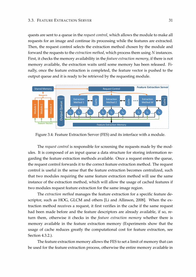
3.3. FEATURE EXTRACTION SERVER 31
quests are sent to a queue in the request control, which allows the module to make allrequests for an image and continue its processing while the features are extracted.Then, the request control selects the extraction method chosen by the module andforward the requests to the extraction method, which process them using N instances.First, it checks the memory availability in the feature extraction memory, if there is notmemory available, the extraction waits until some memory has been released. Fi-nally, once the feature extraction is completed, the feature vector is pushed to theoutput queue and it is ready to be retrieved by the requesting module.
Feature Extraction Server
Cac
he
Cac
he
Cac
he
Feature Vectors
Requests
Mo
dul
e 1
Mo
dul
e K
Mo
dul
e 2
Shared Memory Request Control
Extraction Method 1
Extraction Method 2
Extraction Method M
Feature Extraction Memory
Ou
tpu
t Q
ueu
e
I1 I2 IN I1 I2 IN I2 INI1
Figure 3.4: Feature Extraction Server (FES) and its interface with a module.
The request control is responsible for screening the requests made by the mod-ules. It is composed of an input queue a data structure for storing information re-garding the feature extraction methods available. Once a request enters the queue,the request control forwards it to the correct feature extraction method. The requestcontrol is useful in the sense that the feature extraction becomes centralized, suchthat two modules requiring the same feature extraction method will use the sameinstance of the extraction method, which will allow the usage of cached features iftwo modules request feature extraction for the same image region.
The extraction method manages the feature extraction for a specific feature de-scriptor, such as HOG, GLCM and others [Li and Allinson, 2008]. When the ex-traction method receives a request, it first verifies in the cache if the same requesthad been made before and the feature descriptors are already available, if so, re-turn them, otherwise it checks in the feature extraction memory whether there ismemory available in the feature extraction memory (Experiments show that theusage of cache reduces greatly the computational cost for feature extraction, seeSection 4.3.2.).
The feature extraction memory allows the FES to set a limit of memory that canbe used for the feature extraction process, otherwise the entire memory available in
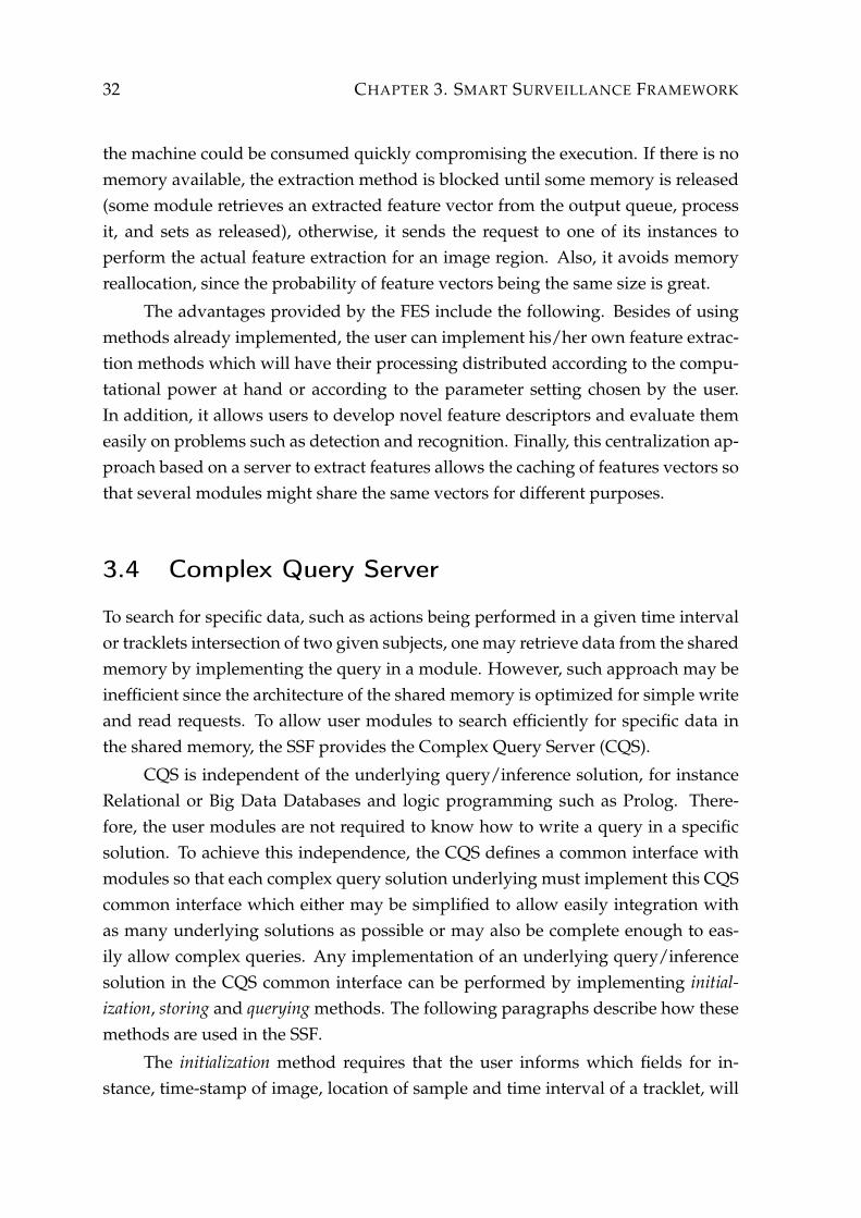
32 CHAPTER 3. SMART SURVEILLANCE FRAMEWORK
the machine could be consumed quickly compromising the execution. If there is nomemory available, the extraction method is blocked until some memory is released(some module retrieves an extracted feature vector from the output queue, processit, and sets as released), otherwise, it sends the request to one of its instances toperform the actual feature extraction for an image region. Also, it avoids memoryreallocation, since the probability of feature vectors being the same size is great.
The advantages provided by the FES include the following. Besides of usingmethods already implemented, the user can implement his/her own feature extrac-tion methods which will have their processing distributed according to the compu-tational power at hand or according to the parameter setting chosen by the user.In addition, it allows users to develop novel feature descriptors and evaluate themeasily on problems such as detection and recognition. Finally, this centralization ap-proach based on a server to extract features allows the caching of features vectors sothat several modules might share the same vectors for different purposes.
3.4 Complex Query Server
To search for specific data, such as actions being performed in a given time intervalor tracklets intersection of two given subjects, one may retrieve data from the sharedmemory by implementing the query in a module. However, such approach may beinefficient since the architecture of the shared memory is optimized for simple writeand read requests. To allow user modules to search efficiently for specific data inthe shared memory, the SSF provides the Complex Query Server (CQS).
CQS is independent of the underlying query/inference solution, for instanceRelational or Big Data Databases and logic programming such as Prolog. There-fore, the user modules are not required to know how to write a query in a specificsolution. To achieve this independence, the CQS defines a common interface withmodules so that each complex query solution underlying must implement this CQScommon interface which either may be simplified to allow easily integration withas many underlying solutions as possible or may also be complete enough to eas-ily allow complex queries. Any implementation of an underlying query/inferencesolution in the CQS common interface can be performed by implementing initial-ization, storing and querying methods. The following paragraphs describe how thesemethods are used in the SSF.
The initialization method requires that the user informs which fields for in-stance, time-stamp of image, location of sample and time interval of a tracklet, will
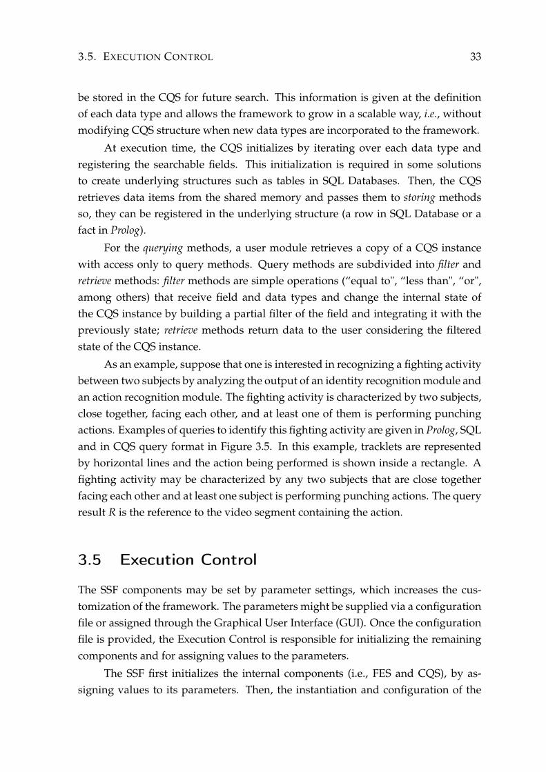
3.5. EXECUTION CONTROL 33
be stored in the CQS for future search. This information is given at the definitionof each data type and allows the framework to grow in a scalable way, i.e., withoutmodifying CQS structure when new data types are incorporated to the framework.
At execution time, the CQS initializes by iterating over each data type andregistering the searchable fields. This initialization is required in some solutionsto create underlying structures such as tables in SQL Databases. Then, the CQSretrieves data items from the shared memory and passes them to storing methodsso, they can be registered in the underlying structure (a row in SQL Database or afact in Prolog).
For the querying methods, a user module retrieves a copy of a CQS instancewith access only to query methods. Query methods are subdivided into filter andretrieve methods: filter methods are simple operations (“equal to", “less than", “or",among others) that receive field and data types and change the internal state ofthe CQS instance by building a partial filter of the field and integrating it with thepreviously state; retrieve methods return data to the user considering the filteredstate of the CQS instance.
As an example, suppose that one is interested in recognizing a fighting activitybetween two subjects by analyzing the output of an identity recognition module andan action recognition module. The fighting activity is characterized by two subjects,close together, facing each other, and at least one of them is performing punchingactions. Examples of queries to identify this fighting activity are given in Prolog, SQLand in CQS query format in Figure 3.5. In this example, tracklets are representedby horizontal lines and the action being performed is shown inside a rectangle. Afighting activity may be characterized by any two subjects that are close togetherfacing each other and at least one subject is performing punching actions. The queryresult R is the reference to the video segment containing the action.
3.5 Execution Control
The SSF components may be set by parameter settings, which increases the cus-tomization of the framework. The parameters might be supplied via a configurationfile or assigned through the Graphical User Interface (GUI). Once the configurationfile is provided, the Execution Control is responsible for initializing the remainingcomponents and for assigning values to the parameters.
The SSF first initializes the internal components (i.e., FES and CQS), by as-signing values to its parameters. Then, the instantiation and configuration of the
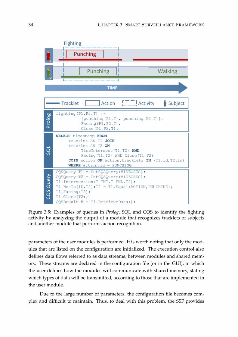
34 CHAPTER 3. SMART SURVEILLANCE FRAMEWORK
fighting(P1,P2,T) :-
[punching(P1,T), punching(P2,T)],
Facing(P1,P2,T),
Close(P1,P2,T).
SELECT timestamp FROM
tracklet AS T1 JOIN
tracklet AS T2 ON
TimeIntersect(T1,T2) AND
Facing(T1,T2) AND Close(T1,T2)
JOIN action ON action.tracklets IN (T1.id,T2.id)
WHERE action.id = PUNCHING
CQSQuery T1 = GetCQSQuery(VIDEOSEG);
CQSQuery T2 = GetCQSQuery(VIDEOSEG);
T1.Intersection(T_INI,T_END,T2);
T1.NotIn(ID,T2);T2 = T1.Equal(ACTION,PUNCHING);
T1.Facing(T2);
T1.Close(T2);
CQSResult R = T1.RetrieveData();
1
2
Fighting
SubjectActivityActionTracklet
Punching Walking
Punching
TIME
Figure 3.5: Examples of queries in Prolog, SQL and CQS to identify the fightingactivity by analyzing the output of a module that recognizes tracklets of subjectsand another module that performs action recognition.
parameters of the user modules is performed. It is worth noting that only the mod-ules that are listed on the configuration are initialized. The execution control alsodefines data flows referred to as data streams, between modules and shared mem-ory. These streams are declared in the configuration file (or in the GUI), in whichthe user defines how the modules will communicate with shared memory, statingwhich types of data will be transmitted, according to those that are implemented inthe user module.
Due to the large number of parameters, the configuration file becomes com-plex and difficult to maintain. Thus, to deal with this problem, the SSF provides
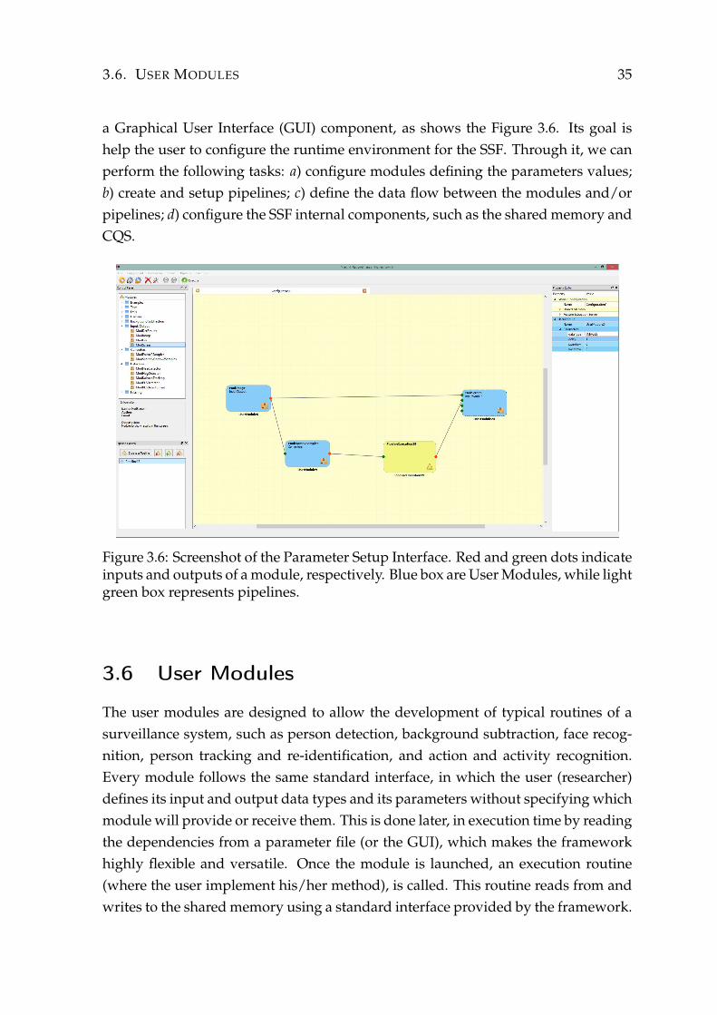
3.6. USER MODULES 35
a Graphical User Interface (GUI) component, as shows the Figure 3.6. Its goal ishelp the user to configure the runtime environment for the SSF. Through it, we canperform the following tasks: a) configure modules defining the parameters values;b) create and setup pipelines; c) define the data flow between the modules and/orpipelines; d) configure the SSF internal components, such as the shared memory andCQS.
Figure 3.6: Screenshot of the Parameter Setup Interface. Red and green dots indicateinputs and outputs of a module, respectively. Blue box are User Modules, while lightgreen box represents pipelines.
3.6 User Modules
The user modules are designed to allow the development of typical routines of asurveillance system, such as person detection, background subtraction, face recog-nition, person tracking and re-identification, and action and activity recognition.Every module follows the same standard interface, in which the user (researcher)defines its input and output data types and its parameters without specifying whichmodule will provide or receive them. This is done later, in execution time by readingthe dependencies from a parameter file (or the GUI), which makes the frameworkhighly flexible and versatile. Once the module is launched, an execution routine(where the user implement his/her method), is called. This routine reads from andwrites to the shared memory using a standard interface provided by the framework.

36 CHAPTER 3. SMART SURVEILLANCE FRAMEWORK
As mentioned in Section 3.2, the modules work independently, in other words,a running module is not aware of the existence of others. This allows the exchange ofmodules of the same type without affecting the operation of the system. Moreover,modules are executed in different threads, which increases the performance of thesystem, enabling real-time processing. For each module is specified what types ofdata it will provide and also, if necessary, what types of data it will consume. Thisway, the module creates information but is not aware of which modules will use it.
Another important feature is the creation of execution pipelines – collections ofuser modules behaving as a single module. A pipeline allows one to group severalmodules of individual methods in a sequence. For instance, Figure 3.7 illustrates aface recognition pipeline which consists of the following modules: a) backgroundsubtraction; b) face detection; and c) face recognition. After defined, multiple in-stances of the pipeline can be launched just by changing their inputs. For instance,one pipeline can be launched to process data from each surveillance camera attachedto the system. Such a feature also makes the framework more scalable.
Background Subtraction
FaceDetection
FaceRecognition
OutputInput
Figure 3.7: Illustration of an execution pipeline.
Since the modules are executed asynchronously, it is the responsibility ofshared memory to perform data synchronization because a module might consumeinformation faster than another module can provide. Figure 3.8 illustrates an exam-ple of synchronization between two modules (M1 and M2) and the shared memory(SM). In the first instant of time (t1), M1 writes a new data item to the SM while M2
reads and processes the current data item in the memory. At time t2, the module M1
is processing, while M2 reads and processes the only available data item. Since thereis no more data to read in t3, M2 is locked until a new information is made avail-able, which occurs in t4. Finally, at t5, M2 is unlocked and performs a new reading.Therefore, by using locking mechanisms in the data reading, the SM is able to syn-chronize dependencies among modules without compromising the performance ofindependent modules.
In real scenarios, it might be relevant that the surveillance system is able to pro-cess different types of sources besides images, such as audio and proximity sensors.To achieve that, users can implement specific data definitions for sensor readingsand process them inside the modules. Another advantage of using user data and
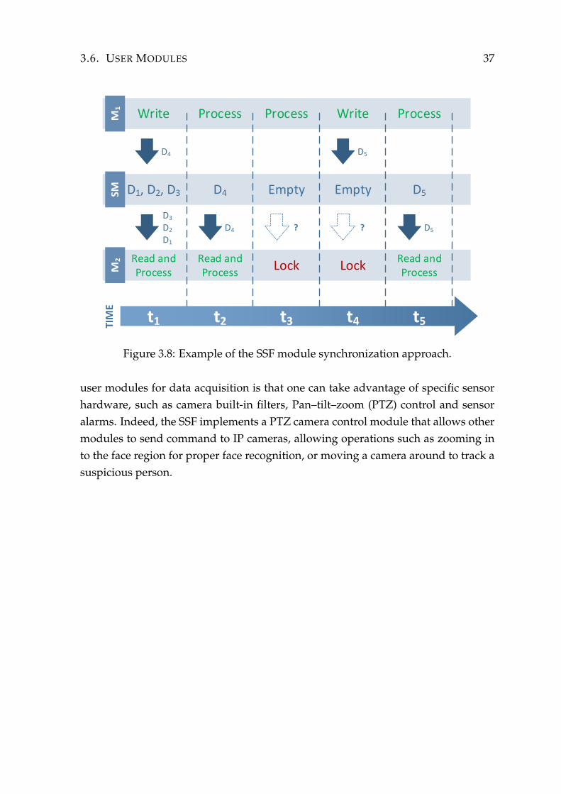
3.6. USER MODULES 37
SM
D4
D3
D2
D1
D4 ?
D5
? D5
D1, D2, D3 EmptyD4 Empty D5
Write ProcessProcess Write Process
Read and Process
Lock LockRead and Process
Read and Process
t1 t2 t3 t4 t5TIM
E
Figure 3.8: Example of the SSF module synchronization approach.
user modules for data acquisition is that one can take advantage of specific sensorhardware, such as camera built-in filters, Pan–tilt–zoom (PTZ) control and sensoralarms. Indeed, the SSF implements a PTZ camera control module that allows othermodules to send command to IP cameras, allowing operations such as zooming into the face region for proper face recognition, or moving a camera around to track asuspicious person.


Chapter 4
Experimental Results
This chapter evaluates important aspects of the framework proposed in this work.Section 4.1 explores the framework scalability, Section 4.2 describes experiments toevaluate the communication latencies caused by the architecture of Shared Memoryand Section 4.3 discusses the performance of the Feature Extraction Server (FES).Finally, Section 4.4 discusses the results obtained.
All experiments were conducted using computer with two Intel R©
XeonTM 2.40GHz processor with 6 physical cores each, 32GB of main memoryand running Windows
TMoperating system.
4.1 Framework Scalability
This section presents two experiments to demonstrate the scalability of the frame-work. The SSF allows the user to perform parallelization of methods by decompos-ing the problem into subproblem. The following will describe briefly the types ofproblem decomposition which are dealt in these experiments.
The goal of a decomposition is to divide the problem into independent sub-problems. They can mostly be written independently. Two general methodologiesare commonly used. The first, termed data decomposition, assumes that the overallproblem consists in executing computational operations or transformations to oneor more data structures and, further, that these data structures may be divided andoperated upon. The second, called task decomposition, divides the work based ondifferent operations or functions. In a sense, the SSF supports both task decomposi-tion (by the decomposition of a large problem into smaller parts, which in turn, areimplemented through the modules) and data decomposition (by the instantiation of
39
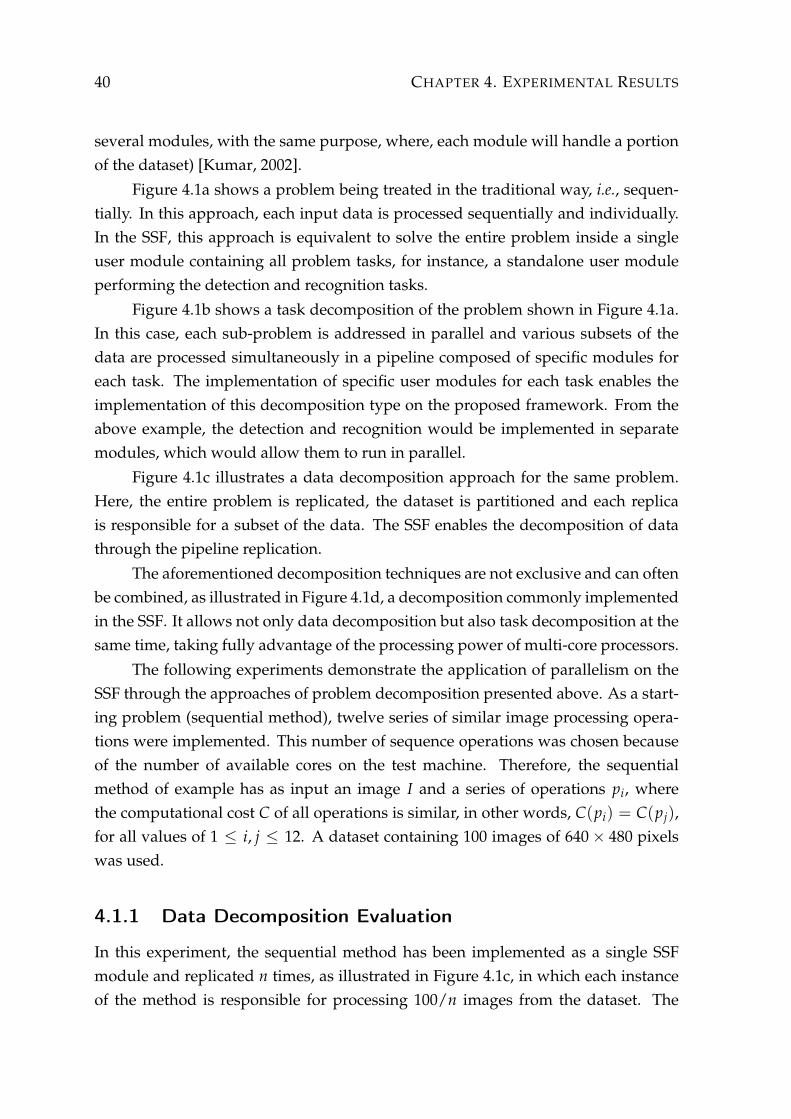
40 CHAPTER 4. EXPERIMENTAL RESULTS
several modules, with the same purpose, where, each module will handle a portionof the dataset) [Kumar, 2002].
Figure 4.1a shows a problem being treated in the traditional way, i.e., sequen-tially. In this approach, each input data is processed sequentially and individually.In the SSF, this approach is equivalent to solve the entire problem inside a singleuser module containing all problem tasks, for instance, a standalone user moduleperforming the detection and recognition tasks.
Figure 4.1b shows a task decomposition of the problem shown in Figure 4.1a.In this case, each sub-problem is addressed in parallel and various subsets of thedata are processed simultaneously in a pipeline composed of specific modules foreach task. The implementation of specific user modules for each task enables theimplementation of this decomposition type on the proposed framework. From theabove example, the detection and recognition would be implemented in separatemodules, which would allow them to run in parallel.
Figure 4.1c illustrates a data decomposition approach for the same problem.Here, the entire problem is replicated, the dataset is partitioned and each replicais responsible for a subset of the data. The SSF enables the decomposition of datathrough the pipeline replication.
The aforementioned decomposition techniques are not exclusive and can oftenbe combined, as illustrated in Figure 4.1d, a decomposition commonly implementedin the SSF. It allows not only data decomposition but also task decomposition at thesame time, taking fully advantage of the processing power of multi-core processors.
The following experiments demonstrate the application of parallelism on theSSF through the approaches of problem decomposition presented above. As a start-ing problem (sequential method), twelve series of similar image processing opera-tions were implemented. This number of sequence operations was chosen becauseof the number of available cores on the test machine. Therefore, the sequentialmethod of example has as input an image I and a series of operations pi, wherethe computational cost C of all operations is similar, in other words, C(pi) = C(pj),for all values of 1 ≤ i, j ≤ 12. A dataset containing 100 images of 640× 480 pixelswas used.
4.1.1 Data Decomposition Evaluation
In this experiment, the sequential method has been implemented as a single SSFmodule and replicated n times, as illustrated in Figure 4.1c, in which each instanceof the method is responsible for processing 100/n images from the dataset. The

4.1. FRAMEWORK SCALABILITY 41
Entire Problem
Task 01 Task 02 Task 03
Data1 Data AData Set
Input Output
(a) Sequential approach to a problem. In the SSF, the entire problem is solved within asingle user module.
Pipeline
Task 01 Task 02
Data1Data Set
Data3 Data2
Task 03
Data4
Input OutputPartial Partial
(b) Task decomposition. In the SSF, each tasks runs in an independent module in par-allel.
Output
Output
Output
Data Set
Data1 Data1
InputEntire Problem (Instance 01)
Task 01 Task 02 Task 03
Data2 Data2
InputEntire Problem (Instance 02)
Task 01 Task 02 Task 03
Data3 Data3
InputEntire Problem (Instance 03)
Task 01 Task 02 Task 03
(c) Data decomposition. In the SSF, the data is split into subsets and each subset ispresented to a sequence of independent modules.
Pipeline 01
Pipeline 02
Pipeline 03
Data Set
Output
Data1
Input
Task 01 Task 02
Data7
Partial
Data4
Partial
Task 03
Data10
Output
Data2
Input
Task 01 Task 02
Data8
Partial
Data5
Partial
Task 03
Data11
Output
Data3
Input
Task 01 Task 02
Data9
Partial
Data6
Partial
Task 03
Data12
(d) Hybrid decomposition. Combination of task and data decomposition.
Figure 4.1: Examples of problem decomposition
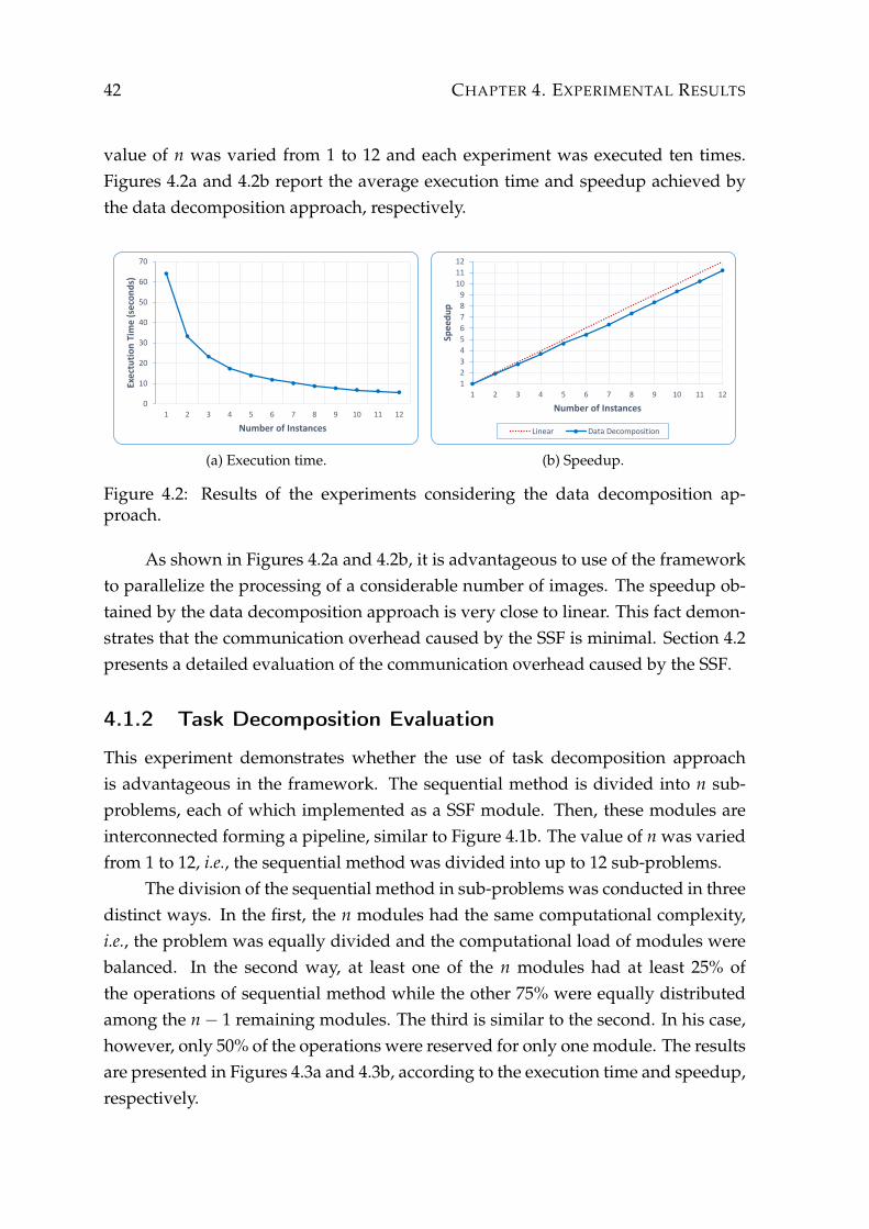
42 CHAPTER 4. EXPERIMENTAL RESULTS
value of n was varied from 1 to 12 and each experiment was executed ten times.Figures 4.2a and 4.2b report the average execution time and speedup achieved bythe data decomposition approach, respectively.
0
10
20
30
40
50
60
70
1 2 3 4 5 6 7 8 9 10 11 12
Exe
ctu
tio
n T
ime
(se
con
ds)
Number of Instances
(a) Execution time.
1
2
3
4
5
6
7
8
9
10
11
12
1 2 3 4 5 6 7 8 9 10 11 12
Spe
edu
p
Number of Instances
Linear Data Decomposition
(b) Speedup.
Figure 4.2: Results of the experiments considering the data decomposition ap-proach.
As shown in Figures 4.2a and 4.2b, it is advantageous to use of the frameworkto parallelize the processing of a considerable number of images. The speedup ob-tained by the data decomposition approach is very close to linear. This fact demon-strates that the communication overhead caused by the SSF is minimal. Section 4.2presents a detailed evaluation of the communication overhead caused by the SSF.
4.1.2 Task Decomposition Evaluation
This experiment demonstrates whether the use of task decomposition approachis advantageous in the framework. The sequential method is divided into n sub-problems, each of which implemented as a SSF module. Then, these modules areinterconnected forming a pipeline, similar to Figure 4.1b. The value of n was variedfrom 1 to 12, i.e., the sequential method was divided into up to 12 sub-problems.
The division of the sequential method in sub-problems was conducted in threedistinct ways. In the first, the n modules had the same computational complexity,i.e., the problem was equally divided and the computational load of modules werebalanced. In the second way, at least one of the n modules had at least 25% ofthe operations of sequential method while the other 75% were equally distributedamong the n− 1 remaining modules. The third is similar to the second. In his case,however, only 50% of the operations were reserved for only one module. The resultsare presented in Figures 4.3a and 4.3b, according to the execution time and speedup,respectively.

4.2. COMMUNICATION LATENCY 43
0
10
20
30
40
50
60
70
80
1 2 3 4 5 6 7 8 9 10 11 12
Exe
ctu
tio
n T
ime
(se
con
ds)
Number of Modules
Balanced Unbalanced (25%) Unbalanced (50%)
(a) Execution time.
123456789
101112
1 2 3 4 5 6 7 8 9 10 11 12
Spe
edu
p
Number of Modules
Balanced Unbalanced (25%)
Unbalanced (50%) Linear
(b) Speedup.
Figure 4.3: Results of the experiments considering task decomposition.
Analyzing the results, one can observe that the task decomposition is success-ful when there is a balance between the parts. Figure 4.3b presents an almost linearspeedup for the case where the operations of the sequential method were dividedequally among the modules. However, the two other examples, in which the divi-sion into sub-tasks was unbalanced, did not show any cost reduction starting from acertain number of modules. For the example where 25% of the operations are underthe responsibility of only one module, the time improvement was observed only forup to 4 modules. From then on, there was no performance gain because the timespent by the module that was overloaded will always be greater than or equal to25% of the total time. To the overhead of 50%, the improvement was observed onlyfor up to 2 modules due to the same reasons previously discussed. This experimentdemonstrates that the task decomposition in SSF can be scalable if conducted in abalanced way.
4.2 Communication Latency
To evaluate the overhead caused by the communication between the modules andthe shared memory, we conducted an experiment in which an image (SSF frame datatype) was transmitted between a certain number of modules. For that, a pipelinewith n modules was created and each module just forwards the image frame (with-out performing any processing) to the next module. The time elapsed between theinstant at which the first and the last module of the pipeline (Modules 01 and n, re-spectively) performed the reading of the image was computed to estimate the datalatency. Figure 4.4 illustrates this experiment.
This experiment considered pipelines with sizes of 1, 3, 5, 7, 10 and 15 mod-

44 CHAPTER 4. EXPERIMENTAL RESULTS
Module 01 Module 02 Module 03 Module n
Frame
Elapsed Time
Stop TimeStart Time
Figure 4.4: Setup of the experiment performed to compute the data latency in theSSF.
ules. In addition, for each pipeline size, executions with 1, 3 and 5 simultaneouspipelines were tested. To perform this experiment, a total of 100 different imageswere transmitted and the average time spent for each move across the pipeline wascalculated. The results are showed in Figure 4.5.
1 3 5 7 10 15
1 pipeline 51,123 57,964 53,734 62,147 64,439 67,519
3 pipelines 53,679 56,851 60,789 69,356 70,239 72,785
5 pipelines 61,194 68,984 70,795 73,240 79,089 81,301
0
10
20
30
40
50
60
70
80
90
Exec
uti
on
Tim
e (
mill
isec
on
ds)
Number of Instances
Figure 4.5: Results of the experiments regarding the data latency for the framework.
Results shown in Figure 4.5 demonstrate that the overhead caused by the in-creased number of modules simultaneously connected to the shared memory is low.Although this overhead exists, it is negligible when compared with the processingtime of the data, usually orders of magnitude higher.
4.3 Feature Extraction Server (FES) Evaluation
This section describes the experiments conducted to evaluate the performance ofthe Feature Extraction Server (FES). The evaluation was conducted using three
4.3. FEATURE EXTRACTION SERVER (FES) EVALUATION 45
traditional methods of features extraction: Pixel Intensity, Histogram of OrientedGradients (HOG) [Dalal and Triggs, 2005] and Gray-Level Co-occurrence Matrix(GLCM) [Haralick et al., 1973]. Even though there are many other feature extrac-tion methods, we have chosen these three methods because they present differentcomputational cost and memory consumption, allowing us to evaluate different as-pects of the Feature Extraction Server (FES).
The experiments consist in extracting feature descriptors of an image with aresolution of 640× 480 pixels, using the aforementioned methods. To represent arealistic scenario, we employ the sliding window algorithm [Forsyth and Ponce,2011], widely used in object detection, to sample the image regions from which thefeature descriptors are extracted. This algorithm works by exhaustively scanning aninput image to generate a set of coordinates of several detection windows in multi-ple scales. For this work, we follow the block setup used in Dalal and Triggs [2005],in which each detection window is split into 105 blocks and we set the stride andscales parameters to generate a total of 48, 495 detection windows per image. Weevaluate the FES regarding two aspects: the performance of parallel feature extrac-tion by increasing the number of extraction instances and improvements obtainedby the cache memory in the feature extraction.
4.3.1 Number of Instances
To demonstrate the performance of parallelism provided by FES, we conducted ex-periments based on the number of instances used in the extraction. Each experimentconsisted in the execution of a method repeated ten times and varying the numberof instances from 1 to 12.
As shown in Figure 4.6, one can observe an improvement in the computa-tional performance as a function of the number of instances used in the FES, whichdemonstrates the advantage of its usage in multi-core environments. The GLCM(Figure 4.6a) method showed a proportional reduction in run time on all experi-ments, while for the other two methods, HOG and intensity, Figures 4.6b and 4.6crespectively, it was only observed up to six instances. In the HOG case, there is aslightly increase in the run time starting from nine instances. This is because thecomputational complexity of HOG and intensity is smaller when compared to theGLCM, hence there is an overhead caused by the FES, starting at nine instances.This behavior can be explained by the Amdahl’s Law1. This law states that a fraction
1Amdahl’s law, also known as Amdahl’s argument, is named after computer architect Gene Amdahl,and is used to find the maximum expected improvement to an overall system when only part of
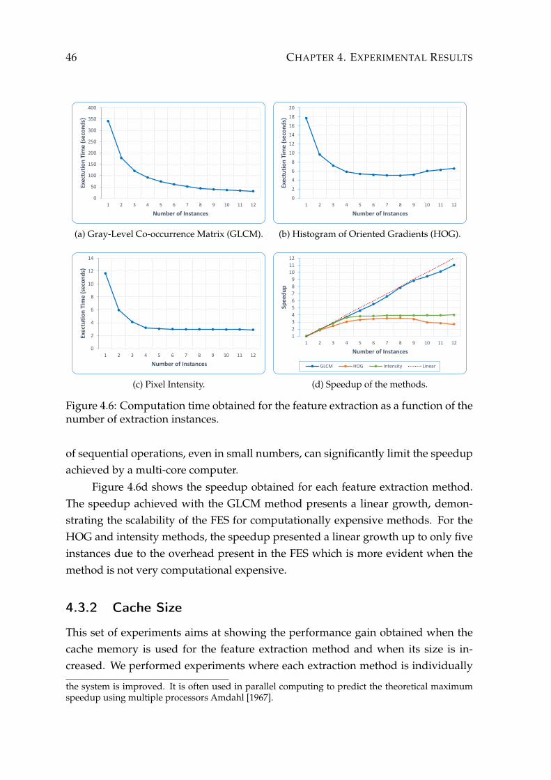
46 CHAPTER 4. EXPERIMENTAL RESULTS
0
50
100
150
200
250
300
350
400
1 2 3 4 5 6 7 8 9 10 11 12
Exec
tuti
on
Tim
e (
seco
nd
s)
Number of Instances
(a) Gray-Level Co-occurrence Matrix (GLCM).
0
2
4
6
8
10
12
14
16
18
20
1 2 3 4 5 6 7 8 9 10 11 12
Exec
tuti
on
Tim
e (
seco
nd
s)
Number of Instances
(b) Histogram of Oriented Gradients (HOG).
0
2
4
6
8
10
12
14
1 2 3 4 5 6 7 8 9 10 11 12
Exec
tuti
on
Tim
e (
seco
nd
s)
Number of Instances
(c) Pixel Intensity.
1
2
3
4
5
6
7
8
9
10
11
12
1 2 3 4 5 6 7 8 9 10 11 12
Spee
du
p
Number of Instances
GLCM HOG Intensity Linear
(d) Speedup of the methods.
Figure 4.6: Computation time obtained for the feature extraction as a function of thenumber of extraction instances.
of sequential operations, even in small numbers, can significantly limit the speedupachieved by a multi-core computer.
Figure 4.6d shows the speedup obtained for each feature extraction method.The speedup achieved with the GLCM method presents a linear growth, demon-strating the scalability of the FES for computationally expensive methods. For theHOG and intensity methods, the speedup presented a linear growth up to only fiveinstances due to the overhead present in the FES which is more evident when themethod is not very computational expensive.
4.3.2 Cache Size
This set of experiments aims at showing the performance gain obtained when thecache memory is used for the feature extraction method and when its size is in-creased. We performed experiments where each extraction method is individually
the system is improved. It is often used in parallel computing to predict the theoretical maximumspeedup using multiple processors Amdahl [1967].

4.3. FEATURE EXTRACTION SERVER (FES) EVALUATION 47
executed for a different cache with at most C entries, where C ∈ {0, 512, 1024,2048, 4096, 8192, 16384, 32768, 65536} by varying the number of instances in 1, 2, 4,and 8. Each experiment was executed ten times. The average computational time isreported in Figure 4.7.
0
50
100
150
200
250
300
350
400
0 512 1024 2048 4096 8192 16384 32768 65536
Exe
cuti
on
Tim
e (
seco
nd
s)
Cache Size
1 Instance 2 Instances 4 Instances 8 Instances
(a) Gray-Level Co-occurrence Matrix (GLCM)
0
2
4
6
8
10
12
14
16
18
20
0 512 1024 2048 4096 8192 16384 32768 65536
Exec
uti
on
Tim
e (
seco
nd
s)
Cache Size
1 Instance 2 Instances 4 Instances 8 Instances
(b) Histogram of Oriented Gradients (HOG)
0
2
4
6
8
10
12
14
0 512 1024 2048 4096 8192 16384 32768 65536
Exec
uti
on
Tim
e (
seco
nd
s)
Cache Size
1 Instance 2 Instances 4 Instances 8 Instances
(c) Pixel Intensity
Figure 4.7: Computation time with the addition of cache memory with multiplesizes (maximum number of entries).
48 CHAPTER 4. EXPERIMENTAL RESULTS
Figure 4.7a shows a significant reduction in time for the GLCM without usingcache (near 80% for a cache of size 512), for every number of instances. The improve-ment is also observed for 1024, 2048, 4096, and 8192 cache size. However, startingfrom 16834 entries, the runtime does not decrease. This is because the number ofextracted features is not enough to fill the entire cache.
The cache utilization also significantly contributed to the performance of HOGand intensity. However, this contribution is only observed when the HOG is per-formed in one or two instances and when the pixel intensity is executed for a singleinstance, although two instances result in a slightly reduction in the run time.
Unlike the previous results, experiments with 4 and 8 instances for HOG andintensity increased the run time due to the overhead caused by competition for ac-cess to the cache, since the low computational cost of the methods yields the in-stances to quickly compute the features and consequently making them wait to haveaccess to write to the cache memory. One may also notice a small increase in runtime for cache values above 8192, which we believe is also caused by poor spatiallocality of the memory.
4.4 Discussion and Remarks
This chapter has presented the experimental evaluation of our proposed framework.In this section, we presented a discussion and remarks of the achieved results.
The experiment regarding the scalability of the framework showed good re-sults with nearly linear speedup in most cases. The data decomposition can be eas-ily implemented in SSF and shows promising results in cases where the dataset canbe partitioned equally. However, partitioning a dataset into several sub-sets is notalways possible, as there may be dependence among the data. The speedup pre-sented by task decomposition only has a linear behavior when the modules havea similar computational cost, which leads us to conclude that the manner of taskdecomposition is performed interferes on the framework scalability.
According to the experiments, the latency of communication between the mod-ules and the shared memory was low, when compared with the time required toperform processing pertaining to video surveillance operations.
Results regarding the Feature Extraction Server (FES) demonstrated that weare able to achieve almost linear speedup, provided that the method is computationintensive, and also demonstrated that enabling cache decreases by 80% the runtime.
Chapter 5
Conclusions
This work proposed a novel framework to allow further development on computervision methods and surveillance applications. The architecture of the Smart Surveil-lance Framework (SSF) allows the simultaneous execution of multiple user modulesthat can be developed independently since they have communication and synchro-nization through a shared memory, which contributes to the scalability and flexibil-ity. The framework also provides two important components, the feature extractionserver and the complex query server, these components maximize the computa-tional resource usage and facilitate the scene understanding, respectively.
The proposed framework will be made publicly available and besides of mak-ing surveillance research using real data and in real-time processing easier, it willalso allow researchers to provide their methods (implemented as modules) to beused by other researchers to compare how results. Nowadays, it is difficult to com-pare results to previously published works since the code is not always available orit is necessary to adapt the code to work on new data sets. By using the SSF, onecan provide the source-code (or just its compiled version) of the module to solve acomputer vision problem and when another researcher proposes a novel solution,he/she can use that module to compare the results different data sets or to comparethe computational cost in the same machine. Therefore, the SSF might also con-tribute to a more accurate validation of computer vision algorithms, mainly thoserelated to surveillance.
5.1 Future Works
As future works, we propose: a) extensions of the SSF to provide new features in-cluding the distribution of the processing and the data to multiple computers to
49

50 CHAPTER 5. CONCLUSIONS
make it even more scalable; b) improvement of the Graphical User Interface (GUI) toallows data processing visualization, which currently is not focus of many researchbut is very useful to provide a better understanding of the behavior of computervision algorithms, mainly when large amounts of data are used and the processingis done in parallel; c) improvement of persistence mechanism in secondary mem-ory using the information of which modules are running and which data requestsare being performed; and, finally, d) the incorporation of security and privacy tothe framework by adding data encryption and user permission levels to preserveperson’s identities, which will allow the SSF to be employed in real surveillanceapplications.

Bibliography
Afrah, A., Miller, G., and Fels, S. (2009). Vision system development through separa-tion of management and processing. In Proceedings of IEEE International Symposiumon Multimedia (IISM 2009), pages 612--617.
Aggarwal, J. and Ryoo, M. (2011). Human activity analysis: A review. ACM Com-puting Surveys, 43(3):1--43. ISSN 0360-0300.
Amdahl, G. M. (1967). Validity of the single processor approach to achieving largescale computing capabilities. In Proceedings of Spring Joint Computer Conference(AFIPS 1967), pages 483--485.
Bedagkar-Gala, A. and Shah, S. K. (2014). A survey of approaches and trends in per-son re-identification. Image and Vision Computing, 32(4):270--286. ISSN 02628856.
Choe, T. E., Deng, H., Guo, F., Lee, M. W., and Haering, N. (2013). Semantic Video-to-Video Search Using Sub-graph Grouping and Matching. In Proceedings on IEEEInternational Conference on Computer Vision Workshops (ICCVW 2013), pages 787--794.
Collins, R., Lipton, A., Kanade, T., and Fujiyoshi, H. (2000). A system for videosurveillance and monitoring. Technical report, Carnegie Mellon University.
Dalal, N. and Triggs, B. (2005). Histograms of oriented gradients for human detec-tion. In Proceedings of IEEE Conference on Computer Vision and Pattern Recognition(CVPR 2005), volume 1, pages 886--893. ISSN 1063-6919.
Davies, A. C. and Velastin, S. A. (2007). A progress review of intelligent cctv surveil-lance systems. In Proceedings of IEEE Intelligent Data Acquisition and Advanced Com-puting Systems (IDAACS 2007), pages 417--423.
de Melo, V. H. C., Leão, S., Menotti, D., and Schwartz, W. R. (2014). An optimizedsliding window approach to pedestrian detection. In Proceedings on InternationalConference on Pattern Recognition (ICPR 2014), pages 1 -- 8.
51
52 BIBLIOGRAPHY
de Siqueira, F. R., Schwartz, W. R., and Pedrini, H. (2013). Multi-scale gray level co-occurrence matrices for texture description. Neurocomputing, 120:336 -- 345. ISSN0925-2312.
Dollar, P., Belongie, S., and Perona, P. (2010). The fastest pedestrian detector in thewest. In Proceedings of the British Machine Vision Conference (BMVC 2010), pages68.1--68.11.
Dollar, P., Tu, Z., Perona, P., and Belongie, S. (2009). Integral channel features. InProceedings of the British Machine Vision Conference (BMVC 2009), pages 91.1--91.11.
Dollár, P., Wojek, C., Schiele, B., and Perona, P. (2012). Pedestrian detection: Anevaluation of the state of the art. IEEE Transactions on Pattern Analysis and MachineIntelligence, 34(4):743--61. ISSN 1939-3539.
Felzenszwalb, P., Girshick, R., McAllester, D., and Ramanan, D. (2010). Object detec-tion with discriminatively trained part-based models. IEEE Transactions on PatternAnalysis and Machine Intelligence, 32:1627--1645. ISSN 0162-8828.
Fleck, S. and Strasser, W. (2008). Smart camera based monitoring system and itsapplication to assisted living. Proceedings of the IEEE, 96(10):1698--1714. ISSN0018-9219.
Fleck, S. and Strasser, W. (2010). Towards secure and privacy sensitive surveillance.In Proceedings of ACM/IEEE International Conference on Distributed Smart Cameras(ICDSC 2010), pages 126--132.
Forsyth, D. A. and Ponce, J. (2011). Computer Vision: A Modern Approach. PrenticeHall Professional Technical Reference. ISBN 0130851981.
Gauglitz, S., Höllerer, T., and Turk, M. (2011). Evaluation of interest point detectorsand feature descriptors for visual tracking. International Journal of Computer Vision,94(3):335--360. ISSN 0920-5691.
Gavrila, D. (1999). The visual analysis of human movement: A survey. ComputerVision and Image Understanding, 73(1):82--98. ISSN 1077-3142.
Gilbert, N. (2007). Dilemmas of privacy and surveillance: Chaljenges of technologi-cal change. Technical report, University of Surrey.
Haering, N., Venetianer, P. L., and Lipton, A. (2008). The evolution of video surveil-lance: An overview. Machine Vision and Applications, 19(5-6):279--290. ISSN 0932-8092.
BIBLIOGRAPHY 53
Hampapur, A. (2008). Smart video surveillance for proactive security. IEEE SignalProcessing Magazine, 25(4):136--134. ISSN 1053-5888.
Hampapur, A., Brown, L., Connell, J., Pankanti, S., and Senior, A. (2003). Smartsurveillance: applications, technologies and implications. In Proceedings of In-ternational Conference on Information, Communications and Signal Processing (ICICS2003), pages 1133--1138.
Hampapur, A., Brown, L., Feris, R., Senior, A., Shu, C. F., Tian, Y., Zhai, Y., andLu, M. (2007). Searching surveillance video. In Proceedings on IEEE Conference onAdvanced Video and Signal Based Surveillance (AVSS 2007), pages 75--80.
Haralick, R. M., Shanmugam, K., and Dinstein, I. (1973). Textural features for imageclassification. IEEE Transactions on Systems, Man, and Cybernetics, 3(6):610--621.ISSN 0018-9472.
Huang, T. (2014). Surveillance video: The biggest big data. Computing Now, 7(2).ISSN 0823-6437.
Kumar, V. (2002). Introduction to Parallel Computing. Addison-Wesley Longman Pub-lishing Co., Inc., 2nd edition. ISBN 0201648652.
Li, J. and Allinson, N. M. (2008). A comprehensive review of current local featuresfor computer vision. Neurocomputing, 71(10-12):1771--1787. ISSN 0925-2312.
Liu, H., Chen, S., and Kubota, N. (2013). Intelligent video systems and analytics:A survey. IEEE Transactions on Industrial Informatics, 9(3):1222--1233. ISSN 1551-3203.
Liu, W., Miller, P., Ma, J., and Yan, W. (2009). Challenges of distributed intelligentsurveillance system with heterogenous information. Proceedings of QRASA, pages69--74.
Lowe, D. G. (2004). Distinctive image features from scale-invariant keypoints. Inter-national Journal of Computer Vision, 60(2):91--110. ISSN 0920-5691.
Marin, J., Vazquez, D., Amores, J., Lopez, A., and Leibe, B. (2013). Random forestsof local experts for pedestrian detection. In Proceedings on IEEE International Con-ference on Computer Vision (ICCV 2013), pages 2592--2599. ISSN 1550-5499.
Mikolajczyk, K. and Schmid, C. (2005). Performance evaluation of local descriptors.IEEE Transactions on Pattern Analysis and Machine Intelligence, 27(10):1615--30. ISSN0162-8828.

54 BIBLIOGRAPHY
Mitra, S. and Acharya, T. (2007). Gesture recognition: A survey. IEEE Transactionson Systems, Man and Cybernetics, Part C (Applications and Reviews), 37(3):311--324.ISSN 1094-6977.
Nascimento, E. R., Schwartz, W. R., and Campos, M. F. M. (2012). Edvd - enhanceddescriptor for visual and depth data. In Proceedings on International Conference onPattern Recognition (ICPR 2012), pages 2776 -- 2779. ISSN 1051-4651.
Nazare, A. C., Santos, C. E., Ferreira, R., and Schwartz, W. R. (2014). Smart surveil-lance framework: A versatile tool for video analysis. In Proceedings of IEEE WinterConference on Applications of Computer Vision (WACV 2014), pages 753--760.
Odobez, J.-M., Carincotte, C., Emonet, R., Jouneau, E., Zaidenberg, S., Ravera, B.,Bremond, F., and Grifoni, A. (2012). Unsupervised activity analysis and moni-toring algorithms for effective surveillance systems. In Proceedings of InternationalConference on Computer Vision (ICCV 2012), pages 675--678.
Piccardi, M. (2004). Background subtraction techniques: A review. In Proceedingsof International Conference on Systems, Man and Cybernetics (ISMC 2004), volume 4,pages 3099--3104. ISSN 1062-922X.
Poppe, R. (2007). Vision-based human motion analysis: An overview. ComputerVision and Image Understanding, 108(1-2):4--18. ISSN 1077-3142.
Poppe, R. (2010). A survey on vision-based human action recognition. Image andVision Computing, 28(6):976--990. ISSN 0262-8856.
Porikli, F., Bremond, F., Dockstader, S., Ferryman, J., Hoogs, A., Lovell, B., Pankanti,S., Rinner, B., Tu, P., and Venetianer, P. (2013). Video surveillance: Past, present,and now the future. IEEE Signal Processing Magazine, 30(3):190--198. ISSN 1053-5888.
Posner, R. A. (2008). Privacy, surveillance, and law. The University of Chicago LawReview, 75(1):245--260. ISSN 0041-9494.
Prisacariu, V. and Reid, I. (2009). fasthog - a real-time gpu implementation of hog.Technical report 2310/09, Department of Engineering Science, Oxford University.
Randen, T. and Husoy, J. (1999). Filtering for texture classification: A comparativestudy. IEEE Transactions on Pattern Analysis and Machine Intelligence, 21(4):291--310.ISSN 0162-8828.
BIBLIOGRAPHY 55
Räty, T. D. (2010). Survey on contemporary remote surveillance systems for publicsafety. IEEE Transactions on Systems, Man and Cybernetics Part C: Applications andReviews, 40(5):493--515. ISSN 1094-6977.
Regazzoni, C. S., Ramesh, V., and Foresti, G. L. (2001). Special issue on video com-munications, processing, and understanding for third generation surveillance sys-tems. Proceedings of the IEEE, 89(10):1355--1539. ISSN 0018-9219.
San Miguel, J. C., Bescós, J., Martínez, J. M., and García, A. (2008). Diva: A dis-tributed video analysis framework applied to video-surveillance systems. In Pro-ceedings of International Workshop on Image Analysis for Multimedia Interactive Ser-vices (IWIAMIS 2008), pages 207--210.
Sedky, M. H., Moniri, M., and Chibelushi, C. C. (2005). Classification of smart videosurveillance systems for commercial applications. In Proceeding of IEEE Interna-tional Conference on Advanced Video and Signal Based Surveillance (AVSS 2005), pages638--643.
Shah, M., Javed, O., and Shafique, K. (2007). Automated visual surveillance in real-istic scenarios. IEEE Multimedia, 14(1):30--39. ISSN 1070-986X.
Siebel, N. T. and Maybank, S. J. (2004). The advisor visual surveillance system. InProcedings of ECCV Workshop Applications of Computer Vision (ECCV-ACV 2004),pages 1--9.
Souza, J., Ferreira, C. A. M., Júnior, C. E. S., de Melo, V. H., and Schwartz, W. (2014).Self-organizing traffic lights: A pedestrian oriented approach. In Proceedings ofSIBGRAPI Workshop of Undergraduate Works (WUW-SIBGRAPI 2014), pages 1--6.
Suvonvorn, N. (2008). A video analysis framework for surveillance system. In Pro-ceedings of IEEE Workshop on Multimedia Signal Processing (MMSP 2008), pages 867--871.
Thornton, J., Baran-Gale, J., Butler, D., Chan, M., and Zwahlen, H. (2011). Person at-tribute search for large-area video surveillance. In Proceedings of IEEE InternationalConference on Technologies for Homeland Security (HST 2011), pages 55–61.
Tian, Y. L., Brown, L., Hampapur, A., Lu, M., Senior, A., and Shu, C. F. (2008). Ibmsmart surveillance system (s3): Event based video surveillance system with anopen and extensible framework. Machine Vision and Applications, 19(5-6):315--327.ISSN 0932-8092.

56 BIBLIOGRAPHY
Valera, M. and Velastin, S. (2005). Intelligent distributed surveillance systems: Areview. IEE Proceedings - Vision, Image, and Signal Processing, 152(2):192. ISSN1350-245X.
van de Sande, K. E. A., Gevers, T., and Snoek, C. G. M. (2010). Evaluating colordescriptors for object and scene recognition. IEEE Transactions on Pattern Analysisand Machine Intelligence, 32(9):1582--96. ISSN 1939-3539.
Vaquero, D. A., Feris, R. S., Tran, D., Brown, L., Hampapur, A., and Turk, M. (2009).Attribute-based people search in surveillance environments. In Proceedings ofWorkshop on Applications of Computer Vision (WACV 2009), pages 1--8.
Venetianer, P. L. and Deng, H. (2010). Performance evaluation of an intelligent videosurveillance system – a case study. Computer Vision and Image Understanding,114(11):1292--1302. ISSN 1077-3142.
Viola, P. and Jones, M. (2001). Rapid object detection using a boosted cascade ofsimple features. In Proceedings of the IEEE Conference on Computer Vision and PatternRecognition (CVPR 2001), volume 1, pages I–511--I–518. ISSN 1063-6919.
Wang, G., Tao, L., Di, H., Ye, X., and Shi, Y. (2012). A Scalable Distributed Archi-tecture for Intelligent Vision System. IEEE Transactions on Industrial Informatics,8(1):91--99. ISSN 1551–3203.
Winkler, T. and Rinner, B. (2010). A systematic approach towards user-centric pri-vacy and security for smart camera networks. In Proceedings of ACM/IEEE Inter-national Conference on Distributed Smart Cameras (ICDSC 2010), pages 133–141.
Xia, J., Rao, W., Huang, W., and Lu, Z. (2013). Automatic multi-vehicle trackingusing video cameras: An improved camshift approach. KSCE Journal of Civil En-gineering, 17(6):1462--1470. ISSN 1226-7988.
Xie, W., Shi, Y., Xu, G., and Mao, Y. (2002). Smart platform - a software infrastructurefor smart space (siss). In Proceedings of IEEE International Conference on MultimodalInterfaces (ICMI 2002), pages 429--434.
Yilmaz, A., Javed, O., and Shah, M. (2006). Object tracking: A survey. ACM Comput-ing Surveys, 38(4):1–45. ISSN 0360-0300.
Zhang, J., Marszałek, M., Lazebnik, S., and Schmid, C. (2007). Local features andkernels for classification of texture and object categories: A comprehensive study.International Journal of Computer Vision, 73(2):213--238. ISSN 0920-5691.

BIBLIOGRAPHY 57
Zhang, X. and Gao, Y. (2009). Face recognition across pose: A review. Pattern Recog-nition, 42(11):2876--2896. ISSN 0031-3203.


Appendix A
Application Example:Self-Organizing Traffic Lights
This appendix on based in Souza et al. [2014] and it described how an applicationcan be developed using the SSF.
The traffic light is a valuable device to control the vehicular and pedestriantraffic. One of its main issues is that several traffic lights might be improperly cali-brated once they do not consider the differences in pedestrian mobility from regionto region. As each region presents different pedestrians with different characteris-tics, there is a need for automatic approaches.
For such purpose, two challenging cases in transport engineering literaturemust be handled. The first case happens when pedestrians with reduced speedcannot cross the street within the available time. The second case happens whenthe traffic light for pedestrians remains open for a long time even when there are nopedestrians waiting to cross. Such problem may be tackled by the same approachesadopted by traditional visual surveillance methods.
The problem can be solved by the following approach, divided in the stepsdepicted in Figure A.1a and Figure A.1b presents the application configuration onthe SSF Graphical User Interface (GUI).
The steps of application are described as follows:
1. First, the pedestrians must be detected using a pedestrian detection method,such as the HOG Detector [Dalal and Triggs, 2005], the LatSVM Detec-tor Felzenszwalb et al. [2010] or [de Melo et al., 2014] (Pedestrian DetectionModule).
59

60 APPENDIX A. APPLICATION EXAMPLE: SELF-ORGANIZING TRAFFIC LIGHTS
Crosswalk Segmentation
Speed & Trajectory Estimation
Pedestriam Detector
Pedestriam Tracking
Video Acquisition
Traffic Light Manager
(a) Workflow of the application example. The pedestrian position in each frame is determined inthe pedestrian detector and pedestrian tracking modules. Then, the pedestrian position is usedto estimate a distribution map where pedestrians walk when crossing the street and to estimatethe speed and trajectory of these pedestrians to set the red flashing time in the pedestrian trafficlight. (Adapted from Souza et al. [2014].)
(b) Configuration of the Traffic Light application.
Figure A.1: Self-Organizing Traffic Lights application example.
2. Based on the detected pedestrians, one must follow the pedestrians based ona tracking approach to estimate where they are heading to and their velocity(Tracking Module).
3. The next step is splitted into two parts. The first part handles the crosswalksegmentation based on the pedestrian’s velocity (Crosswalk SegmentationModule). In this scenario, pedestrians that are moving belongs to the cross-walk, while non-moving pedestrians are more likely to be at the crosswalk’sborder. The second part estimates the speed and trajectory of each pedestrian(Speed Module).
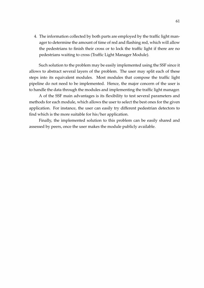
61
4. The information collected by both parts are employed by the traffic light man-ager to determine the amount of time of red and flashing red, which will allowthe pedestrians to finish their cross or to lock the traffic light if there are nopedestrians waiting to cross (Traffic Light Manager Module).
Such solution to the problem may be easily implemented using the SSF since itallows to abstract several layers of the problem. The user may split each of thesesteps into its equivalent modules. Most modules that compose the traffic lightpipeline do not need to be implemented. Hence, the major concern of the user isto handle the data through the modules and implementing the traffic light manager.
A of the SSF main advantages is its flexibility to test several parameters andmethods for each module, which allows the user to select the best ones for the givenapplication. For instance, the user can easily try different pedestrian detectors tofind which is the more suitable for his/her application.
Finally, the implemented solution to this problem can be easily shared andassessed by peers, once the user makes the module publicly available.