Arquitecturas de Hardware para um Veículo Eléctrico
140
Faculdade de Engenharia da Universidade do Porto Arquitecturas de Hardware para um Veículo Eléctrico André Manuel Paiva e Rocha Dissertação realizada no âmbito do Mestrado Integrado em Engenharia Electrotécnica e de Computadores Major Automação Orientador: Prof. Doutor Paulo Portugal Março de 2011
Transcript of Arquitecturas de Hardware para um Veículo Eléctrico
Faculdade de Engenharia da Universidade do Porto
Arquitecturas de Hardware para um Veículo Eléctrico
André Manuel Paiva e Rocha
Dissertação realizada no âmbito do Mestrado Integrado em Engenharia Electrotécnica e de Computadores
Major Automação
Orientador: Prof. Doutor Paulo Portugal
Março de 2011

© André Manuel Paiva e Rocha, 2011

i
Resumo
A indústria automóvel tem vindo ao longo dos anos a sofrer uma evolução exponencial. Os
veículos modernos estão cada vez mais a ser dotados de funcionalidades que providenciam
uma maior segurança, conforto, eficiência e performance. Estas funcionalidades são baseadas
não só em sistemas computacionais isolados, mas resultam também da interacção entre vários
sistemas, que são suportados por várias redes de comunicação de dados com requisitos e
aplicações distintas.
À medida que os componentes mecânicos têm vindo a ser substituidos por equivalentes
electrónicos, são exigidos a estes níveis de confiança elevados no seu funcionamento, que
podem apenas ser atingidos com o recurso a técnicas de concepção de arquitecturas
tolerantes a falhas.
Este trabalho apresenta uma visão geral de várias funcionalidades que podem ser
encontradas nos veículos modernos, das arquitecturas e redes de comunicação que suportam
o seu funcionamento, e de algumas das técnicas de concepção que permitem aumentar a
confiança que pode ser depositada no funcionamento destes sistemas. Por fim, é apresentada
uma proposta para uma arquitectura de um sistema de travagem com requisitos de segurança
crítica.

ii
iii
Abstract
The automotive industry has been evolving over the years in an exponential fashion.
Modern vehicles are increasingly being provided with features which provide greater security,
comfort, safety and performance. These features are not only based in isolated
computational systems, but also result from the interaction between various systems, which
are supported by several data communication networks with distinct requirements and
applications.
As mechanical components are being replaced by their equivalent electronic, higher
levels of dependability are being demanded from these, which can only be attained by means
of fault tolerant design techniques.
This work presents an overview of the various features that can be found on modern
vehicles, the architectures and communication networks that support their operation, and
some of the design techniques which allow an increase of their dependability. Finally, a
proposal for the architecture of a braking system with safety critical requirements is
presented.

iv

v
Agradecimentos
Aos meus pais por me terem feito acreditar que o caminho mais difícil é o que mais
compensa, e por me terem dado todas as condições e mais algumas para que tivesse sucesso.
Ao Prof. Doutor Paulo Portugal, não só pelo seu profissionalismo, mas também pela sua
capacidade de motivação, indispensável nos momentos mais complicados deste trabalho.
À Joana, por todo o apoio que me deu e por continuar comigo após esta longa ausência.
A todos os meus amigos que de algum modo procuraram ajudar.

vi

vii
"All the so called secrets of success will not work unless you do"
Unknown Author

viii
ix
Contents
Resumo ............................................................................................ i
Abstract ...........................................................................................iii
Agradecimentos ..................................................................................v
Contents .......................................................................................... ix
List of Figures ................................................................................. xiii
List of Tables ................................................................................. xvii
Symbols and Acronyms....................................................................... xix
Chapter 1 ......................................................................................... 1
Introduction ..................................................................................................... 1
1.1 Motivation ............................................................................................... 1 1.2 Objectives ............................................................................................... 2 1.3 Document Structure ................................................................................... 2
Chapter 2 ......................................................................................... 5
In-Vehicle systems ............................................................................................. 5
2.1 Introduction ............................................................................................ 5 2.2 Automotive Systems ................................................................................... 5
2.2.1 Powertrain ....................................................................................... 5 2.2.2 Chassis ............................................................................................ 6 2.2.3 Body .............................................................................................. 6 2.2.4 Passive Safety ................................................................................... 7 2.2.5 Human-Machine-Interfaces (HMI) ............................................................ 7 2.2.6 Infotainment and Telematics ................................................................ 7
2.3 Braking Systems ........................................................................................ 8 2.3.1 Antilock Braking System (ABS) ............................................................... 8 2.3.2 Traction Control System (TCS) ............................................................. 14 2.3.3 Electronic Stability Control (ESC) ......................................................... 15 2.3.4 Electronic Brake Force Distribution (EBD) ............................................... 19 2.3.5 Electronic Brake Assist (EBA) ............................................................... 20 2.3.6 Architecture of Braking ECUs .............................................................. 21
2.4 Instrument Panels ................................................................................... 21 2.4.1 Information to Display ....................................................................... 21 2.4.2 Instrument Panel Architectures ............................................................ 23

x
2.5 Steering Systems ..................................................................................... 25 2.5.1 Hydraulic Power Steering ................................................................... 26 2.5.2 Hybrid and Electric Power Steering ....................................................... 27 2.5.3 Power Steering Architecture ............................................................... 29 2.5.4 Four Wheel Steering (4WS) ................................................................. 30
2.6 Exterior Lighting Systems .......................................................................... 32 2.6.1 Automatic Lighting ........................................................................... 33 2.6.2 Fused Light Detection ....................................................................... 33 2.6.3 Dynamic Headlight Range Adjustment ................................................... 33 2.6.4 Adaptive Cornering Light ................................................................... 35 2.6.5 Camera Based Lighting Systems ........................................................... 36 2.6.6 Lighting Systems Architecture ............................................................. 39
2.7 Propulsion System ................................................................................... 40 2.7.1 Regenerative Braking ........................................................................ 40 2.7.2 Cruise Control ................................................................................. 41
2.8 Adaptive Cruise Control (ACC) .................................................................... 41
Chapter 3 ........................................................................................ 43
In-Vehicle Networks ......................................................................................... 43
3.1 Introduction .......................................................................................... 43 3.2 Network Requirements for the Different Automotive Domains ............................. 44 3.3 In-vehicle Network Classifications ................................................................ 45
3.3.1 Class A Networks ............................................................................. 45 3.3.2 Class B Networks ............................................................................. 45 3.3.3 Class C Networks ............................................................................. 45 3.3.4 Class D Networks ............................................................................. 45
3.4 Communication Networks for the Automotive Industry....................................... 46 3.5 Controller Area Network ........................................................................... 47
3.5.1 CAN Nodes Interaction Model .............................................................. 48 3.5.2 Bus Access ..................................................................................... 48 3.5.3 CAN Frames ................................................................................... 49 3.5.4 Overload Frames ............................................................................. 52 3.5.5 Error Detection, Processing and Management .......................................... 52 3.5.6 Fault Confinement Strategy ................................................................ 53
3.6 Flexray ................................................................................................. 54 3.6.1 Bus Access ..................................................................................... 55 3.6.2 Static Segment ................................................................................ 56 3.6.3 Dynamic Segment ............................................................................ 57 3.6.4 Symbol Window ............................................................................... 57 3.6.5 Network Idle Time ........................................................................... 57 3.6.6 Flexray Frame ................................................................................ 58 3.6.7 Error Processing, Management and Transmission Security ........................... 59
3.7 Local Interconnect Network (LIN) ................................................................ 60 3.7.1 LIN Frames..................................................................................... 61 3.7.2 BUS Access ..................................................................................... 62 3.7.3 Error Processing and Management ........................................................ 64
3.8 Time Triggered Ethernet (TTEthernet) .......................................................... 64 3.8.1 Operational Principles and Architectures ................................................ 65 3.8.2 Types of Messages ............................................................................ 66 3.8.3 Reliability and Fault Tolerance ............................................................ 66
Chapter 4 ........................................................................................ 69
Drive-by-wire systems and guidelines for fault tolerant hardware design ........................ 69
4.1 Motivation for this Chapter ........................................................................ 69 4.2 Introduction to Drive-by-wire Systems .......................................................... 69
4.2.1 Obstacles on the Implementation of Drive-by-wire Systems ......................... 72 4.3 Drive-by-wire Systems .............................................................................. 72
xi
4.3.1 Brake-by-wire ................................................................................. 72 4.3.2 Steer-by-wire ................................................................................. 74
4.4 Fault Tolerant Hardware Architectures Design ................................................. 74 4.4.1 X-by-wire Requirements for the Automotive Industry ................................. 76 4.4.2 Increasing Dependability .................................................................... 77
4.5 Fail Safe Units ........................................................................................ 81 4.5.1 Master/checker Approach .................................................................. 82 4.5.2 Duplication with Comparison ............................................................... 82
4.6 Hardware for Safety Critical Systems ............................................................ 82 4.6.1 Integrated Voltage Regulators ............................................................. 82 4.6.2 Voltage Monitors .............................................................................. 82 4.6.3 Memory Protection Unit (MPU) ............................................................. 82 4.6.4 Error Correction Code Protected memories (ECC) ..................................... 83 4.6.5 Clock Monitoring Units ...................................................................... 83 4.6.6 Peripheral Components Replication....................................................... 83 4.6.7 Watchdog Timers ............................................................................. 83 4.6.8 Dual Core Microcontrollers for Safety Applications .................................... 83
Chapter 5 ........................................................................................ 85
Architecture Definition ..................................................................................... 85
5.1 High Level Architecture ............................................................................ 86 5.1.1 Architecture Limitations .................................................................... 87 5.1.2 Data Exchange between ECUs .............................................................. 87 5.1.3 ECU Services .................................................................................. 88
5.2 Braking System Architecture....................................................................... 90 5.2.1 Braking Architecture Network Proposal .................................................. 93 5.2.2 Gateway........................................................................................ 93 5.2.3 Brake Pedal Position Module ............................................................... 95 5.2.4 Wheel Speed Acquisition Module ......................................................... 100 5.2.5 ABS, TCS and ESC Modules ................................................................. 102 5.2.6 Braking Actuator Modules .................................................................. 104 5.2.7 Power Supplies ............................................................................... 107 5.2.8 Braking System Fault Analysis ............................................................. 109
Chapter 6 ...................................................................................... 113
Conclusions and Future Work ............................................................................. 113
6.1 Conclusions .......................................................................................... 113 6.2 Future Work ......................................................................................... 114
References .................................................................................... 115

xii
xiii
List of Figures
Figure 1.1 - Tesla roadster, a fully electric sports vehicle ............................................. 1
Figure 2.1 - Relationship between the adhesion coefficient and wheel slip in different road conditions [10]. ................................................................................... 9
Figure 2.2 - Relationship between brake slip, lateral force coefficient, and coefficient of friction [11] .............................................................................................. 9
Figure 2.3 - ABS preventing wheel lock-up .............................................................. 10
Figure 2.4 - Symbolic Nomenclature ..................................................................... 10
Figure 2.5 - One channel ABS .............................................................................. 11
Figure 2.6 - Different arrangements for two channel ABS systems. Front wheels facing down ..................................................................................................... 11
Figure 2.7 - Three channel ABS configuration .......................................................... 12
Figure 2.8 - Four channel ABS system .................................................................... 12
Figure 2.9 - Architecture of the Antilock Braking System ............................................ 13
Figure 2.10 - Architecture of the Antilock Braking System with an ASIC for sensor processing and distribution .......................................................................... 13
Figure 2.11 - Vehicle in a split friction coefficient surface .......................................... 14
Figure 2.12 - Duality between ABS and TCS [11]. ...................................................... 15
Figure 2.13 - Vehicle side slip angle ...................................................................... 16
Figure 2.14 - Relationship between the yaw moment and the side slip angle [11] .............. 16
Figure 2.15 - Vehicle experiencing under and over steering ......................................... 17
Figure 2.16 - ESC operation during over steering ...................................................... 18
Figure 2.17 - ESC operation during understeering ..................................................... 18
Figure 2.18 - Electronic Stability Control architecture ............................................... 19
xiv
Figure 2.19 - EBD applying more brake force at the front wheels in a front engine car ........ 20
Figure 2.20 - EBA actuation ................................................................................ 20
Figure 2.21 - Instrument panel point-to-point architecture example .............................. 23
Figure 2.22 - Instrument panel networked architecture example .................................. 24
Figure 2.23 - Hydraulic power steering system applied to a rack-and-pinion configuration [20] ...................................................................................................... 26
Figure 2.24 - Power steering hydraulic pump [20] ..................................................... 27
Figure 2.25 - Power steering assist curve [22].......................................................... 28
Figure 2.26 - Electric power steering [24] .............................................................. 29
Figure 2.27 - Power steering architecture .............................................................. 29
Figure 2.28 : Ackerman drive geometry ................................................................. 30
Figure 2.29 : 4WD decrease of turning radius .......................................................... 30
Figure 2.30 - 4WD at high speeds ......................................................................... 31
Figure 2.31 - Increased stability of the 4WS system when compared to 2WS [28] ............... 31
Figure 2.32 - 4WS Jeep Hurricane [29] .................................................................. 31
Figure 2.33 - 4WS architecture ............................................................................ 32
Figure 2.34 - Vehicle with headlights on ................................................................ 34
Figure 2.35 - Range of headlights increased due to forward tilt .................................... 34
Figure 2.36 - Dynamic headlights range adjustment maintaining headlight range despite of vehicle tilt .............................................................................................. 34
Figure 2.37 - Dynamic Headlight Range Adjustment Architecture .................................. 35
Figure 2.38 - Vehicle without adaptive cornering light system ..................................... 35
Figure 2.39 - Vehicle equipped with adaptive light cornering system ............................. 36
Figure 2.40 - Adaptive cutoff line ........................................................................ 37
Figure 2.41 - Glare free system ........................................................................... 37
Figure 2.42 - Marking light system evidencing a pedestrian ......................................... 38
Figure 2.43 - BMW night vision system ................................................................... 39
Figure 2.44 - Lighting systems' architecture ............................................................ 39
Figure 2.45 - Propulsion system architecture ........................................................... 40
Figure 2.46 - Adaptive Cruise Control maintaining a constant headway time [33] .............. 41
xv
Figure 3.1 - Reduction of number of wiring by means of interconnecting ECUs in a network . 43
Figure 3.2 - CAN arbitration procedure in a wired-and bus [38] .................................... 48
Figure 3.3 - CAN data frame [40] ......................................................................... 49
Figure 3.4 - Standard format of CAN frame arbitration and control fields [40] .................. 50
Figure 3.5 - Extended format of CAN arbitration and control fields [40] .......................... 50
Figure 3.6 - CAN error frame structure [40] ............................................................ 52
Figure 3.7 - Transitions between error states in CAN ................................................. 54
Figure 3.8 - Flexray topologies [42] ...................................................................... 55
Figure 3.9 - Flexray communication cycle .............................................................. 55
Figure 3.10 - Flexray static segment ..................................................................... 56
Figure 3.11 - Flexray in-cycle control .................................................................... 56
Figure 3.12 - Minislots in the dynamic segment ........................................................ 57
Figure 3.13 - Minislot expansion .......................................................................... 57
Figure 3.14 - Flexray frame [42] .......................................................................... 58
Figure 3.15 - Message delay in a two channel Flexray network ..................................... 60
Figure 3.16 - LIN as a sub-bus of CAN [38] .............................................................. 61
Figure 3.17 - LIN frame [44] ............................................................................... 61
Figure 3.18 - LIN bus access [44] .......................................................................... 63
Figure 3.19 - Unconditional frames transfer [44] ...................................................... 63
Figure 3.20 - Event triggered frames transfer [44] .................................................... 64
Figure 3.21 - TTEthernet redundant architecture [45] ............................................... 65
Figure 3.22 - TTEthernet multiple redundant channels [45] ......................................... 67
Figure 4.1 - Citroen C5 by wire: acceleration and braking integrated in the steering wheel [48] ...................................................................................................... 70
Figure 4.2 - General Motors Hy-wire concept car [49] ............................................... 70
Figure 4.3 - Fault tolerant architecture [50] ........................................................... 71
Figure 4.4 - ETC mechanism in internal combustion engines [52] .................................. 71
Figure 4.5 - Electro hydraulic brakes scheme [50] ..................................................... 73
Figure 4.6 - Electro mechanical brake-by-wire [50] ................................................... 73
Figure 4.7 - Continental electro mechanical brake [55] .............................................. 74

xvi
Figure 4.8 - N modular redundancy ...................................................................... 78
Figure 4.9 - Static redundancy applied to steer-by-wire ............................................. 78
Figure 4.10 - Standby spare architecture concept ..................................................... 79
Figure 4.11 - Standby sparing applied to steering actuators ......................................... 80
Figure 4.12 - Standby sparing applied to brake-by-wire .............................................. 80
Figure 4.13 - Pair and spare architecture ............................................................... 81
Figure 4.14 - Pair and spare architecture applied to brake-by-wire ............................... 81
Figure 4.15 - MPC5643L block diagram [63] ............................................................. 84
Figure 5.1 - High level view of the proposed architecture ........................................... 86
Figure 5.2 - Braking system architecture ................................................................ 92
Figure 5.3 - Gateway ........................................................................................ 94
Figure 5.4 -Time frame of messages delivered to the main element .............................. 95
Figure 5.5 - Brake pedal position module ............................................................... 96
Figure 5.6 - Unsynchronized units ........................................................................ 96
Figure 5.7 - Synchronism diagram ........................................................................ 97
Figure 5.8 - Synchronism algorithm ...................................................................... 97
Figure 5.9 - Brake pedal depression dynamics ......................................................... 98
Figure 5.10 - Fault detection by observation of a plausible brake pedal depression ............ 99
Figure 5.11 - Brake pedal position module algorithm ................................................. 99
Figure 5.12 - Wheel speed acquisition module ........................................................ 100
Figure 5.13 - Algorithm for ensuring fail safe behavior of wheel speed acquisition modules. 101
Figure 5.14 - Algorithm for achieving fail safe operation applicable to the ABS, ESC and TCS systems ........................................................................................... 103
Figure 5.15 - Erroneous operation of the brake actuator ........................................... 104
Figure 5.16 - Detailed view of brake actuator module connections ............................... 105
Figure 5.17 - Algorithm which ensures the fail safe of brake actuator elements ............... 106
Figure 5.18 - Algorithm which checks if actuator behavior corresponds to desired behavior 107
Figure 5.19 - Different responses from the vehicle according to different configurations of power supplies upon power outage ............................................................... 108
xvii
List of Tables
Table 3.1 - Automotive domains and their major requirements. Based in [7] ................... 44
Table 3.2 - CAN standards ................................................................................. 47
Table 4.1 - Risk classification according to IEC 61508................................................ 75
Table 4.2 - Interpretation of the various risk levels according to IEC 61508 ..................... 75
Table 4.3 - IEC 61508 safety integrity levels for continuous mode of operation ................ 75
Table 4.4 - IEC 61508 safety integrity levels for on demand mode of operation ................ 76
Table 5.1 - Motor variables of interest .................................................................. 87
Table 5.2- Lights ECU variables of interest ............................................................ 87
Table 5.3 - Brake ECU variables of interest ............................................................ 88
Table 5.4 - Steering ECU variables of interest ......................................................... 88
Table 5.5 - Output of the main element according to incoming messages ....................... 95
Table 5.6 - Gateway fault analysis ...................................................................... 109
Table 5.7 - Network channels fault analysis .......................................................... 109
Table 5.8 - Brake pedal position fault analysis ....................................................... 110
Table 5.9 - ABS, TCS and ESC modules fault analysis ................................................ 110
Table 5.10 - Brake actuator modules fault analysis ................................................. 110
Table 5.11 - Wheel speed acquisition module fault analysis ....................................... 111
Table 5.12 - Power supply fault analysis............................................................... 111

xviii

xix
Symbols and Acronyms
4WS - Four Wheel Steering
ABS – Antilock Braking System
ACC - Adaptive Cruise Control
ASIC - Application Specific Integrated Circuit
CAN - Controller Area Network
CRC - Cyclic Redundancy Check
CSMA/CD - Carrier Sense Multiple Access with Collision Detection
DEEC - Departamento de Engenharia Electrotécnica e Computadores
EBA - Electronic Brake Assist
EBD - Electronic Brake Force Distribution
ECU - Electronic Control Unit
EHB - Electro Hydraulic Brake
EMB - Electro Mechanical Brake
ESC - Electronic Stability Control
ETA - Event Tree Analysis
ETC - Electronic Throttle Control
EV - Electric Vehicle
FEUP - Faculdade de Engenharia da Universidade do Porto
FMEA - Failure Modes and Effects Analysis
FSU - Fail Silent Unit
FTA - Fault Tree Analysis
FTU - Fault Tolerant Unit
HCU - Hydraulic Control Unit
LED - Light Emitting Diode
LIN - Local Interconnect Network
LSB - Least Significant Bit
MCU - Microcontroller Unit
MOST - Media Oriented Systems Transport
MSB - Most Significant Bit
RPM - Revolutions Per Minute
TDMA - Time Division Multiple Access
TTEthernet - Time Triggered Ethernet

xx

1
Chapter 1
Introduction
1.1 Motivation
Recent environmental concerns allied to a decrease in the available sources of fossil fuel
are leading vehicle manufacturers to invest on the development of alternative transportation
methods. The use of electrical energy on vehicles is promising, since it can be obtained in a
more efficient way with a lower impact on the environment [1].
Even when the energy which supplies electric vehicles (EVs) is obtained by means of
polluting fuel sources such as coal, crude or oil, the efficiency provided by electric vehicle
powertrains results in cleaner ecological footprints when comparing to internal combustion
engine (ICE) vehicles [2, 3]. The future is even brighter, as efforts are widely being put
together to convert carbon emitting power stations into clean renewable sources of energy,
motivated by European Union targets of having at least 20% of the energy consumed coming
from renewable resources until the year of 2020 [4].
It has been demonstrated that the acceleration, speed and handling of electric vehicles
can equal or exceed that of ICE vehicles [5]. Moreover, electric vehicles produce less noise
and emit zero tailpipe gases, making them the appropriate choice for use in urban
transportation.
Figure 1.1 - Tesla roadster, a fully electric sports vehicle

2 Introduction
The department of electrical and computer engineering (DEEC) at the Faculty of
Engineering of the University of Porto (FEUP) has just finished building a new laboratory
which will host the development of many projects related with EVs. This new infrastructure
will allow students to develop solutions related to EVs along their academic career.
Several features which provide greater safety, comfort, efficiency and performance, are
being increasingly integrated in modern vehicles. The information about such features, their
hardware architectures, the communication networks that support their operation, and the
techniques used by manufacturers to provide them with the required dependability levels, is
significantly widespread.
The agglomeration of such information on a single document will allow students to easily
move for the actual implementation of these features.
1.2 Objectives
Two main objectives have been defined for this thesis. The first objective is the
elaboration of a survey covering:
The various features that are commonly found on modern vehicles, their general
concepts of operation, and the hardware architectures which support their
behavior
The networking solutions used in the automotive industry which support the
behavior of the identified features
The second objective of this work is the proposal of a conceptual architecture for the
braking system whose implementation can be achieved taking in consideration:
The background obtained by students along their academic career
The feasibility of the braking system by the students
The availability and cost of the components that will support the proposed
architecture
The aspects of dependability in which a braking system much rely on
1.3 Document Structure
This document is divided into 6 chapters. Chapter 1 presents the motivation behind this work and the objectives that have been defined. Chapter 2 provides an overview on the systems that are commonly found in modern vehicles, their major requirements, and a closer look on the systems which are considered to be a priority for the development of projects within the context of the new automotive laboratory. Chapter 3 addresses the networking solutions which are used to interconnect the systems referred in Chapter 2. Controller area network (CAN), local interconnect network (LIN) and Flexray are presented due to their actual importance in the automotive industry. TTEthernet is presented as a promising solution for future vehicles.

Document Structure 3
Chapter 4 presents the emerging concept of by-wire systems applied to the automotive industry. Several techniques and ideas that can be used by students to increase the dependability of their systems are introduced in this chapter. Chapter 5 presents the proposed hardware architecture for the braking system architecture and the algorithms which support its dependability. Chapter 6 overviews all of the work that has been done and future work.

4 Introduction

5
Chapter 2
In-Vehicle systems
2.1 Introduction
The first part of this chapter starts with an overview of the different systems that can be
usually found on vehicles. Afterwards, several of these systems which are considered to be a
priority for the development of the EV project are explored with further detail.
2.2 Automotive Systems
The various subsystems that compose a vehicle can be classified into several domains
according to their functionalities. The number and name of these domains varies along the
literature [6, 7]. In this section, seven domains are considered and an overview of typical
systems and requirements is presented.
2.2.1 Powertrain
The powertrain enclosures the systems that are responsible for converting power into the
motion of the vehicle. Examples of systems in the powertrain domain are
the propulsion system controller which has the task of controlling the propulsion
device (which can be an electric motor or an internal combustion engine)
according to the driver's inputs and requests from other systems, such as the
electronic stability control, traction control system or adaptive cruise control.
automatic transmission controllers
battery management systems
Systems belonging to this domain are characterized by:
High computational power to deal with the complex algorithms that support the
control of the propulsion and transmission devices
Low sampling/actuation times to allow for smooth control
6 In-Vehicle systems
Hard real-time requirements
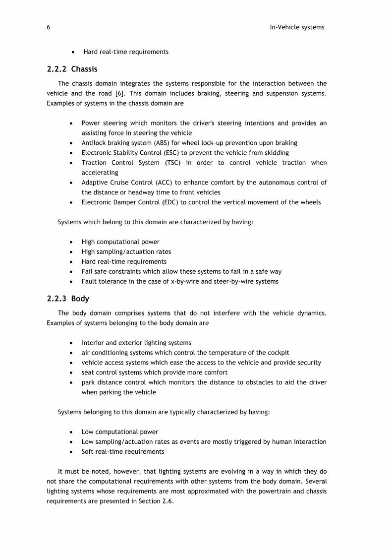
2.2.2 Chassis
The chassis domain integrates the systems responsible for the interaction between the
vehicle and the road [6]. This domain includes braking, steering and suspension systems.
Examples of systems in the chassis domain are
Power steering which monitors the driver's steering intentions and provides an
assisting force in steering the vehicle
Antilock braking system (ABS) for wheel lock-up prevention upon braking
Electronic Stability Control (ESC) to prevent the vehicle from skidding
Traction Control System (TSC) in order to control vehicle traction when
accelerating
Adaptive Cruise Control (ACC) to enhance comfort by the autonomous control of
the distance or headway time to front vehicles
Electronic Damper Control (EDC) to control the vertical movement of the wheels
Systems which belong to this domain are characterized by having:
High computational power
High sampling/actuation rates
Hard real-time requirements
Fail safe constraints which allow these systems to fail in a safe way
Fault tolerance in the case of x-by-wire and steer-by-wire systems
2.2.3 Body
The body domain comprises systems that do not interfere with the vehicle dynamics.
Examples of systems belonging to the body domain are
interior and exterior lighting systems
air conditioning systems which control the temperature of the cockpit
vehicle access systems which ease the access to the vehicle and provide security
seat control systems which provide more comfort
park distance control which monitors the distance to obstacles to aid the driver
when parking the vehicle
Systems belonging to this domain are typically characterized by having:
Low computational power
Low sampling/actuation rates as events are mostly triggered by human interaction
Soft real-time requirements
It must be noted, however, that lighting systems are evolving in a way in which they do
not share the computational requirements with other systems from the body domain. Several
lighting systems whose requirements are most approximated with the powertrain and chassis
requirements are presented in Section 2.6.
Automotive Systems 7
2.2.4 Passive Safety
Passive safety systems operate in order to reduce the effects of a crash. Examples of
systems belonging to this domain are:
Airbag systems which deploy inflatable envelops upon impact according to the
type (front impact, lateral impact) and severity of impact, with the intention of
reducing shocks applied to the driver
Seat belt pretensioners which maintain the driver in a steady position during
crashes and sudden vehicle movements
Systems belonging to this domain are typically characterized by having:
High computational power
High sampling/actuation rates
Hard real-time requirements
Fail safe constraints
2.2.5 Human-Machine-Interfaces (HMI)
HMI systems provide the interaction between the driver and the vehicle. Examples of
systems belonging to this domain are:
Instrument panels which provide information on the status of many of the vehicle
variables of interest such as speed, rpm, fuel level among others
Tire pressure management systems which monitor tire pressure and informs the
driver of possible dangerous situations
Systems belonging to this domain are typically characterized by having:
Low to high computational power depending on the complexity of the display
systems
Medium sampling/actuation times, congruent with human perception
Soft real time requirements
2.2.6 Infotainment and Telematics
Infotainment and telematics systems provide information, entertainment and the
interaction between the vehicle and the exterior world. Examples of systems belonging to this
domain are:
Global positioning systems that provide the driver with information on its
location, direction and speed
Audio Systems
DVD Players
Fleet management systems which allows the tracking of vehicles
Vehicle internet connection

8 In-Vehicle systems
Systems belonging to this domain are typically characterized by having:
Very high computational power
Soft real-time requirements
2.3 Braking Systems
This section presents an overview of the features and architectures of braking systems.
Braking systems are safety critical on their nature. This means that the failure of these
systems to perform their expected operations can result in a catastrophic event, such as the
damage of the vehicle and ultimately the injury or dead of people and environmental harm.
The architectures of braking systems are therefore conceived taking in consideration the
required dependability for their operation. Throughout this section, these systems are
presented without the consideration of these issues as general references for the
development of safety critical systems are given Chapter 4.
The architectures presented in this chapter may reflect slight adaptations from the
studied systems. Therefore, several details that do not contribute for the understanding or
the concepts involved were omitted.
2.3.1 Antilock Braking System (ABS)
According to [8], the ABS system reduces fatal collisions with pedestrians in thirteen
percent and achieves a twelve percent reduction in collisions between vehicles on wet roads.
The ABS was proven to grant more efficiency in nonfatal crashes, reducing the overall crash
rate by six percent for passenger cars and eight percent for light trucks and vans.
The ABS is a safety-related feature that assists the driver in deceleration of the vehicle in
poor or marginal braking conditions, such as wet, icy or sandy pavements [9].
When the driver presses the brake pedal, a force is generated on the wheels which
counteracts its motion. Depending on the surface in which the wheels are spinning, this
braking force can achieve a value that can cause the wheels to slip.
The relationship between the vehicle speed and the slip of the wheel is denominated
brake slip and is defined as the ratio between the speed of the wheel and the speed of the
vehicle itself
𝜆 =𝑆𝑣𝑒𝑖𝑐𝑙𝑒 − 𝑆𝑤𝑒𝑒𝑙
𝑆𝑣𝑒𝑖𝑐𝑙𝑒
× 100%
𝑤𝑒𝑟𝑒:
𝜆: 𝑏𝑟𝑎𝑘𝑒 𝑠𝑙𝑖𝑝
𝑆𝑣𝑒𝑖𝑐𝑙𝑒 : 𝑠𝑝𝑒𝑒𝑑 𝑜𝑓 𝑡𝑒 𝑣𝑒𝑖𝑐𝑙𝑒 (𝑚𝑒𝑡𝑒𝑟𝑠/𝑠𝑒𝑐𝑜𝑛𝑑)
𝑆𝑤𝑒𝑒𝑙 : 𝑠𝑝𝑒𝑒𝑑 𝑜𝑓 𝑡𝑒 𝑤𝑒𝑒𝑙 (𝑚𝑒𝑡𝑒𝑟𝑠/𝑠𝑒𝑐𝑜𝑛𝑑)
(2.1)
Figure 2.1 illustrates the relationship between the wheel slip and the adhesion coefficient
of the wheels for several surfaces. The higher the adhesion coefficient is, the more braking
force is effectively used to reduce vehicle speed and consequently its stopping distance.
Braking Systems 9
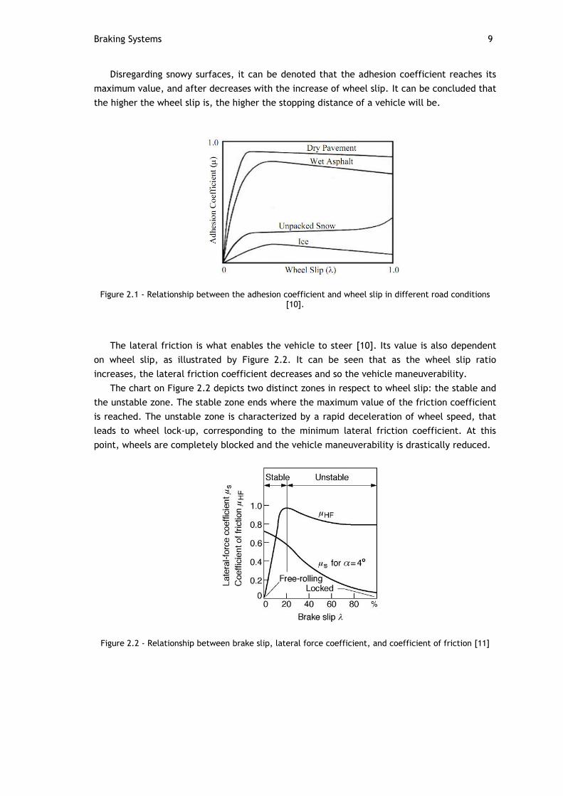
Disregarding snowy surfaces, it can be denoted that the adhesion coefficient reaches its
maximum value, and after decreases with the increase of wheel slip. It can be concluded that
the higher the wheel slip is, the higher the stopping distance of a vehicle will be.
Figure 2.1 - Relationship between the adhesion coefficient and wheel slip in different road conditions [10].
The lateral friction is what enables the vehicle to steer [10]. Its value is also dependent
on wheel slip, as illustrated by Figure 2.2. It can be seen that as the wheel slip ratio
increases, the lateral friction coefficient decreases and so the vehicle maneuverability.
The chart on Figure 2.2 depicts two distinct zones in respect to wheel slip: the stable and
the unstable zone. The stable zone ends where the maximum value of the friction coefficient
is reached. The unstable zone is characterized by a rapid deceleration of wheel speed, that
leads to wheel lock-up, corresponding to the minimum lateral friction coefficient. At this
point, wheels are completely blocked and the vehicle maneuverability is drastically reduced.
Figure 2.2 - Relationship between brake slip, lateral force coefficient, and coefficient of friction [11]

10 In-Vehicle systems
2.3.1.1 ABS Operation
The objective of the ABS system is to ensure that the brakes operate near their most
efficient point, therefore granting steering control at all times and shorter stopping distances
[12]. This is achieved by controlling wheel slip so that its value is kept below the unstable
zone. Wheel slip is controlled by controlling the force applied to the brakes.
The ABS constantly monitors wheel speed for situations that might indicate wheel slip
approaching the unstable zone. If such situation is detected, the brake force applied is
prevented to be raised any further. In case that the wheel slip steps into the unstable zone,
the ABS reduces brake force so wheel slip is taken back into the stable zone. To avoid under
braking and maximize braking efficiency, the brake force is then increased and the process
repeats itself.
An example of the braking force modeled by the ABS against the braking force that would
be applied without ABS is illustrated on Figure 2.3. In red it can be seen the driver’s braking
intension while at blue the actual brake intensity performed by the ABS system on one of the
wheels in order to prevent lock-up.
Figure 2.3 - ABS preventing wheel lock-up
2.3.1.2 Types of ABS
According to the number of wheels whose braking is individually controlled, the ABS can
be implemented in four main distinct ways. The number of control channels on the ABS refers
to the number of wheels that are individually controlled.
Figure 2.4 - Symbolic Nomenclature
Single Channel ABS
The single channel ABS is the most simple and inexpensive type of ABS. It consists on a
ABS controller, a sensor that is placed on the differential or axle of rear wheels and an

Braking Systems 11
actuator controlling brake force in both rear wheels at the same time. No front wheel slip is
detected and rear wheel slip is only detected when both wheels are slipping.
Figure 2.5 - One channel ABS
Two Channel ABS
The different configurations of two channel ABS are organized below in Figure 2.6.
Figure 2.6 - Different arrangements for two channel ABS systems. Front wheels facing down
A: The brake force applied to both front wheels corresponds to the brake force
required for achieving the highest possible friction coefficient on any of the wheels.
Therefore, one of the front wheels may block and rear wheels are only controlled
when both lock-up
B: One rear and one front wheel is monitored. The applied braking force ensures that
the sensed wheels do not block
C: Both of the front wheels are sensed separately and the braking force is applied
diagonally
12 In-Vehicle systems
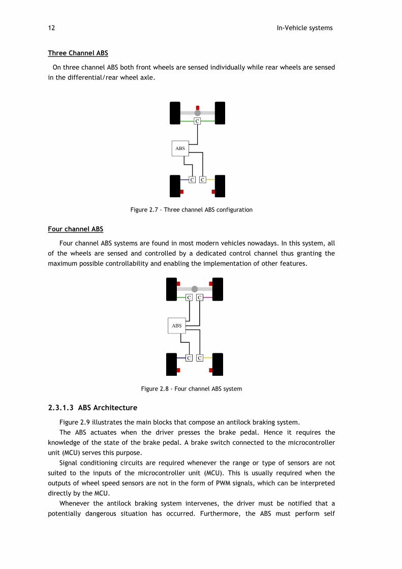
Three Channel ABS
On three channel ABS both front wheels are sensed individually while rear wheels are sensed
in the differential/rear wheel axle.
Figure 2.7 - Three channel ABS configuration
Four channel ABS
Four channel ABS systems are found in most modern vehicles nowadays. In this system, all
of the wheels are sensed and controlled by a dedicated control channel thus granting the
maximum possible controllability and enabling the implementation of other features.
Figure 2.8 - Four channel ABS system
2.3.1.3 ABS Architecture
Figure 2.9 illustrates the main blocks that compose an antilock braking system.
The ABS actuates when the driver presses the brake pedal. Hence it requires the
knowledge of the state of the brake pedal. A brake switch connected to the microcontroller
unit (MCU) serves this purpose.
Signal conditioning circuits are required whenever the range or type of sensors are not
suited to the inputs of the microcontroller unit (MCU). This is usually required when the
outputs of wheel speed sensors are not in the form of PWM signals, which can be interpreted
directly by the MCU.
Whenever the antilock braking system intervenes, the driver must be notified that a
potentially dangerous situation has occurred. Furthermore, the ABS must perform self

Braking Systems 13
diagnostics in order to detect faulty units. The network interface serves these purposes,
interconnecting the ABS with the systems that perform driver notification.
Figure 2.9 - Architecture of the Antilock Braking System
Figure 2.10 depicts an alternative architecture for the ABS. All sensor acquisition circuitry
are placed in a application specific integrated circuit (ASIC). A dedicated microcontroller
computes sensor values and, through a network interface such as CAN or Flexray (discussed in
Chapter 3) delivers the state of all variables of interest. This enables relieving the main ABS
MCU processing requirements. The ASIC can be provided with safety related mechanisms such
as temperature sensors, watchdog timers and other safety related devices, so more
dependability and computational relief of the ABS is achieved.
Figure 2.10 - Architecture of the Antilock Braking System with an ASIC for sensor processing and distribution
14 In-Vehicle systems
2.3.2 Traction Control System (TCS)
When starting off on low frictional coefficient surfaces, excessive throttle can cause the
driving wheels to slip, making it harder or even impossible for the driver to move the vehicle.
This situation frequently happens when vehicles start off on icy or wet pavements, as the
required throttle to move the vehicle is lesser than the driver with its inputs can perform.
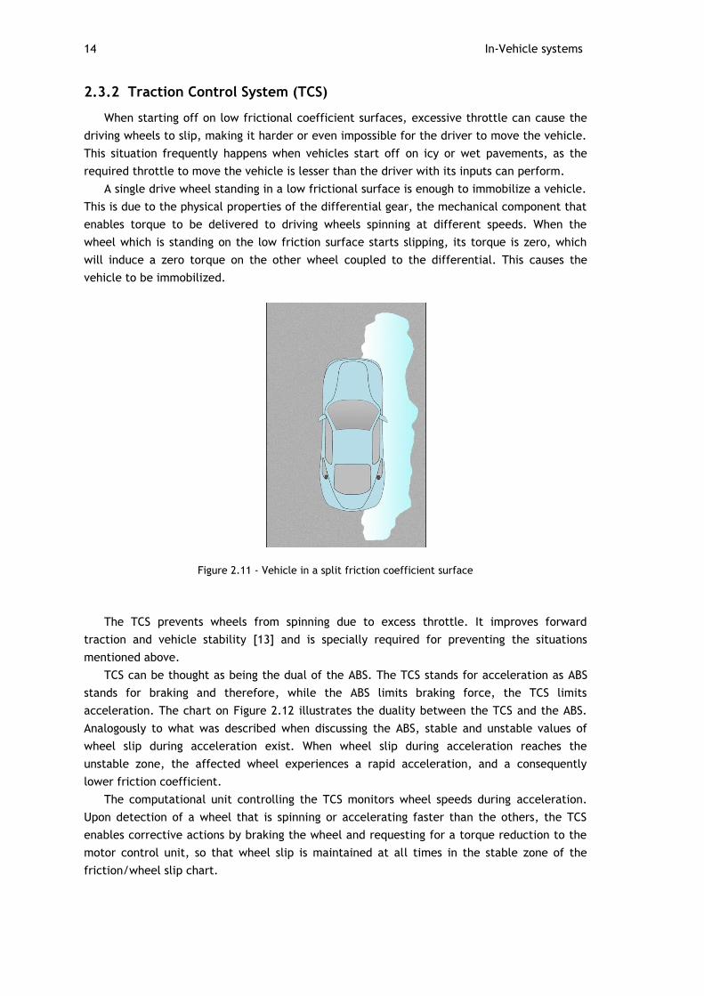
A single drive wheel standing in a low frictional surface is enough to immobilize a vehicle.
This is due to the physical properties of the differential gear, the mechanical component that
enables torque to be delivered to driving wheels spinning at different speeds. When the
wheel which is standing on the low friction surface starts slipping, its torque is zero, which
will induce a zero torque on the other wheel coupled to the differential. This causes the
vehicle to be immobilized.
Figure 2.11 - Vehicle in a split friction coefficient surface
The TCS prevents wheels from spinning due to excess throttle. It improves forward
traction and vehicle stability [13] and is specially required for preventing the situations
mentioned above.
TCS can be thought as being the dual of the ABS. The TCS stands for acceleration as ABS
stands for braking and therefore, while the ABS limits braking force, the TCS limits
acceleration. The chart on Figure 2.12 illustrates the duality between the TCS and the ABS.
Analogously to what was described when discussing the ABS, stable and unstable values of
wheel slip during acceleration exist. When wheel slip during acceleration reaches the
unstable zone, the affected wheel experiences a rapid acceleration, and a consequently
lower friction coefficient.
The computational unit controlling the TCS monitors wheel speeds during acceleration.
Upon detection of a wheel that is spinning or accelerating faster than the others, the TCS
enables corrective actions by braking the wheel and requesting for a torque reduction to the
motor control unit, so that wheel slip is maintained at all times in the stable zone of the
friction/wheel slip chart.

Braking Systems 15
Figure 2.12 - Duality between ABS and TCS [11].
In vehicles equipped with electronic throttle control (ETC), torque reduction is achieved
by controlling the throttle electronically. In internal combustion engine vehicles which are
not equipped with ETC, torque reduction is achieved by means of reducing/suppressing the
spark of one or more cylinders.
As the TCS main composing blocks and principles are shared with the ABS, generally both
units operate in the same electronic control unit (ECU).
2.3.3 Electronic Stability Control (ESC)
The electronic stability control (ESC) is an active safety system developed by Bosch in the
90’s and, according to [14], it is extremely successful in reducing not only fatal crashes but
also other crash involvements. The United States National Highway Traffic Safety
Administration issued a report pointing a reduction in 35% in passenger car accidents and 67%
reduction in SUV accidents, both for single car accidents [14]. This crash reduction rate in
vehicles equipped with the ESC, made it that every new automobile sold in the United States
from 2012 on will have ESC mandatorily.
In optimal conditions where no wheel slip is observed, when a driver steers a vehicle a
yaw momentum is generated. This yaw momentum is responsible for the change in the vehicle
direction. However, when the vehicle is skidding, i.e. its direction is not congruent with the
wheels direction, the generated yaw is diminished and consequently the steering effect. This
may result in loss of the vehicle control by the driver.
The slip angle is a measure of the amount of skidding a vehicle is experiencing. Figure
2.13 depicts a skidding vehicle in which the slip angle β can be observed.

16 In-Vehicle systems
Figure 2.13 - Vehicle side slip angle
The relationship between the yaw moment and the slip angle for a set of steering
angles varying from -4 to +4 is given on the chart on Figure 2.14.
It can be noticed that the greater the slip angle is, the less effect a steering action by
the driver will be actually turned into the pretended steering effect. Also, two different
situations can happen: when the required yaw moment is bigger than the actual yaw moment
(understeering) and when the required yaw moment is smaller than the actual needed
(oversteering). These situations are depicted in Figure 2.15.
Figure 2.14 - Relationship between the yaw moment and the side slip angle [11]

Braking Systems 17
Figure 2.15 - Vehicle experiencing under and over steering
The objective of the ESC system is to guarantee that the driver steering intentions are
actually performed by the vehicle.
2.3.3.1 ESC Operation
Firstly through vehicle dynamics calculations, the ESC must determine how the vehicle
should be behaving with the driver’s inputs. These are the steering wheel angle, the brake
pedal pressure and the throttle position.
The vehicle's ideal behavior is then compared with its actual behavior. The actual
behavior of the vehicle is obtained with aid of yaw moment sensors, lateral acceleration
sensors and wheel speed sensors. If the actual behavior of the vehicle differs from the ideal
behavior by a certain amount, called the threshold, the ESC kicks in by sending commands to
the motor control ECU and to the brake actuators so a counteracting yaw that compensates
the skidding effect is generated.
In case of oversteering and understeering situations, the brake forces applied to
stabilize the vehicle are as high as the deviation between the ideal and the actual behavior of
the vehicle.
Figure 2.16 illustrates an oversteering situation. As the vehicle direction starts pointing
to the center of the curve, the ESC system detects the discrepancy between the driver inputs
and the vehicle behavior and tries to minimize it by applying a counteracting yaw moment.
This counteracting yaw moment is achieved by applying brake pressure on the right front
wheel. As expected, if this discrepancy raises, so the counteracting yaw must raise and
therefore the brake pressure is increased on sequence 3. As the vehicle goes back to the
desired direction, the brake pressure on the right front wheel is progressively decreased until
the vehicle behavior corresponds to the driver inputs.
18 In-Vehicle systems
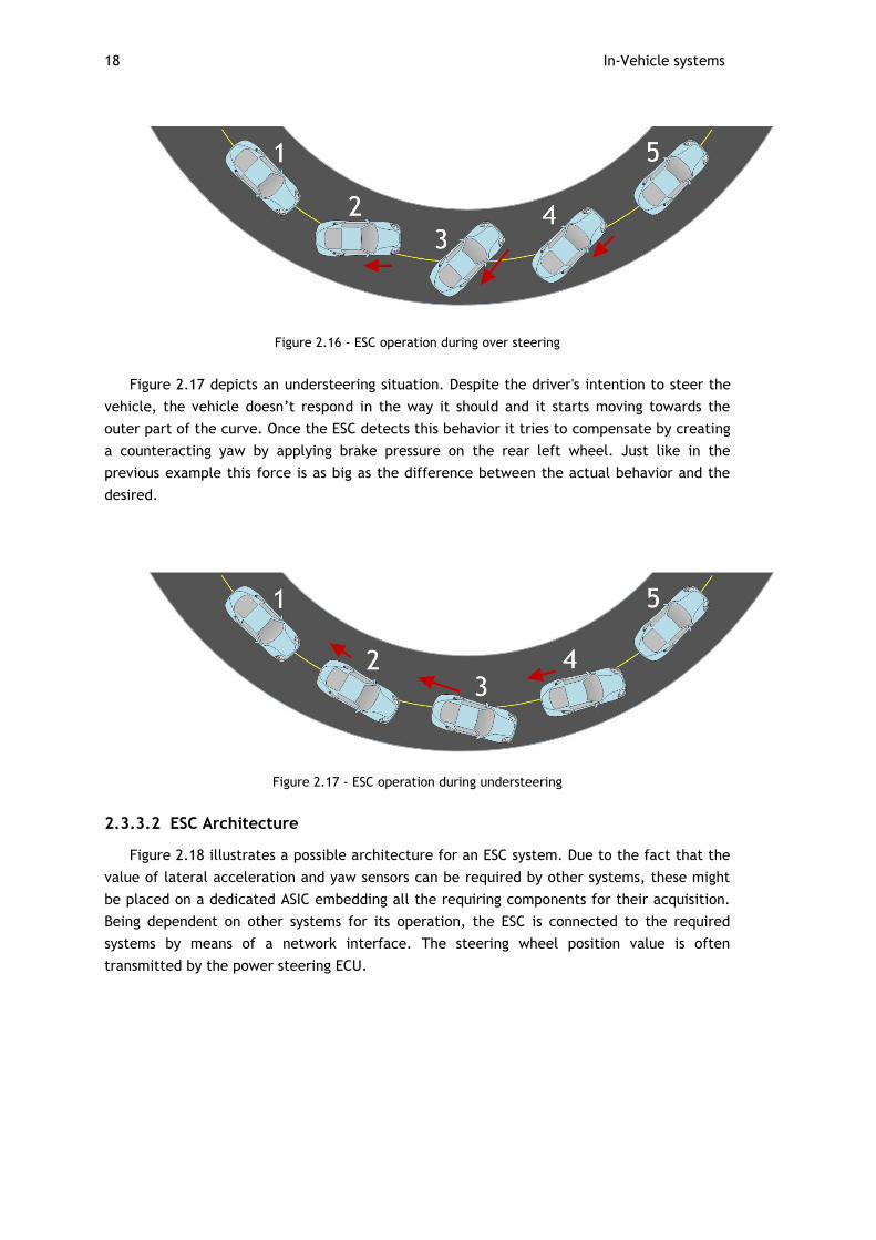
Figure 2.16 - ESC operation during over steering
Figure 2.17 depicts an understeering situation. Despite the driver's intention to steer the
vehicle, the vehicle doesn’t respond in the way it should and it starts moving towards the
outer part of the curve. Once the ESC detects this behavior it tries to compensate by creating
a counteracting yaw by applying brake pressure on the rear left wheel. Just like in the
previous example this force is as big as the difference between the actual behavior and the
desired.
Figure 2.17 - ESC operation during understeering
2.3.3.2 ESC Architecture
Figure 2.18 illustrates a possible architecture for an ESC system. Due to the fact that the
value of lateral acceleration and yaw sensors can be required by other systems, these might
be placed on a dedicated ASIC embedding all the requiring components for their acquisition.
Being dependent on other systems for its operation, the ESC is connected to the required
systems by means of a network interface. The steering wheel position value is often
transmitted by the power steering ECU.

Braking Systems 19
Figure 2.18 - Electronic Stability Control architecture
2.3.4 Electronic Brake Force Distribution (EBD)
EBD allows vehicles to stop in shorter distances by distributing brake force according to
the distribution of weight among the vehicle [15].
Due to the fact that weight is not evenly distributed in vehicles, each wheel supports a
different load. The load that a wheel has to support is also dependent on the dynamics of the
vehicle. When braking in a straight line the weight shifts from the rear to the front of the
vehicle while when braking during turns the weight is shifted to the outer part of the vehicle
in relation to the turn. The more weight a wheel is supporting, the better grip it has and
therefore the more braking force can be applied to it. The EBD takes advantage of this
physical fact.
The EBD adjusts the ratio between front/rear or left/right brake forces so the braking
effect is maximized. Wheel speeds are constantly monitored and, upon detection of wheel
slip due to low load, brake force is increased on higher loaded wheels.
The EBD can be seen as an upgrade of the ABS system as it uses the same components and
therefore only a change in the algorithm is needed to implement an EBD braking system [16].
20 In-Vehicle systems
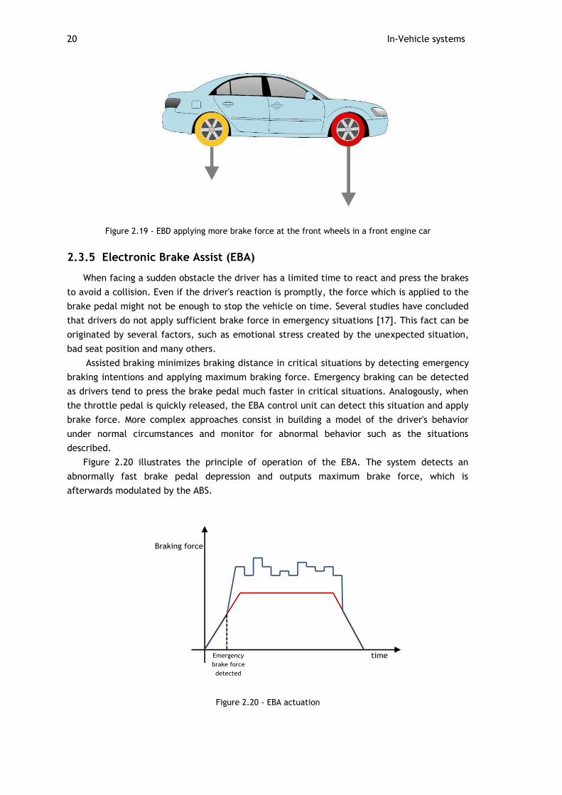
Figure 2.19 - EBD applying more brake force at the front wheels in a front engine car
2.3.5 Electronic Brake Assist (EBA)
When facing a sudden obstacle the driver has a limited time to react and press the brakes
to avoid a collision. Even if the driver's reaction is promptly, the force which is applied to the
brake pedal might not be enough to stop the vehicle on time. Several studies have concluded
that drivers do not apply sufficient brake force in emergency situations [17]. This fact can be
originated by several factors, such as emotional stress created by the unexpected situation,
bad seat position and many others.
Assisted braking minimizes braking distance in critical situations by detecting emergency
braking intentions and applying maximum braking force. Emergency braking can be detected
as drivers tend to press the brake pedal much faster in critical situations. Analogously, when
the throttle pedal is quickly released, the EBA control unit can detect this situation and apply
brake force. More complex approaches consist in building a model of the driver's behavior
under normal circumstances and monitor for abnormal behavior such as the situations
described.
Figure 2.20 illustrates the principle of operation of the EBA. The system detects an
abnormally fast brake pedal depression and outputs maximum brake force, which is
afterwards modulated by the ABS.
Figure 2.20 - EBA actuation
Instrument Panels 21
2.3.6 Architecture of Braking ECUs
All of the systems described from Sections 2.3.1 through Sections 2.3.5 are usually
embedded in the same ECU. Hence, an architecture capable of serving the operation of the
referred systems was already presented in Figure 2.18.
In a small minority of the studied wiring diagrams from different manufacturers, it was
observed that the ESC and TCS can be implemented in separate control modules. In these
cases, the interaction between the ESC or TCS and the ABS brake unit, where the BA and EBD
are implemented, is done by means of a communication network. When required, these
systems request braking actions to the ABS unit so its task can be accomplished.
2.4 Instrument Panels
Displaying the right information to the driver is crucial for the good handling and
management of the vehicle. It permits the driver to have a better perception of his driving,
adapt it according to the surrounding conditions and be aware of problems with the vehicle
that can result in undesirable or dangerous situations.
In this section, the data that must be presented to the driver, its sources and how these
interconnect with the instrument panel are presented.
2.4.1 Information to Display
2.4.1.1 Vehicle Speed
Drivers naturally sense vehicle speed through a combination of their sensations: their
vision, engine noise, and handling feel, or road feel as it is commonly known. However,
vehicles are becoming more comfortable and some of the features that contribute to a more
comfortable vehicle are enemies from the drivers' speed perception. Vehicles are becoming
less noisy due to a better engine/motor performance and a better cabin noise insulation. At
the same time almost every vehicle is equipped with power steering or steer by wire systems
(in the near future) which shades or eliminates road feel.
This means that the driver's sensorial input signals are being attenuated. In this way,
drivers are becoming less likely to have a good prediction about their travelling speed. Also,
drivers tend to underestimate their travelling speed which can lead to not respecting speed
limits which may lead to a dangerous driving behavior [18]. Therefore, it is crucial for the
driver to know its travelling speed as this information serves as feedback for its control
attitudes over the vehicle.
The speed of a vehicle is generally acquired in two different ways:
1. Through a vehicle speed sensor that is placed on the transmission and connected
to the motor/engine ECU.
2. By means of wheel speed sensors used in braking systems.

22 In-Vehicle systems
2.4.1.2 Motor Revolutions per Minute (RPM)
Motor revolutions per minute provides the driver with an estimation of the effort that is
being performed by the motor. It enables the driver to keep that effort below its nominal
value and not overload the motor.
RPM can be acquired by means of a rotational speed sensor placed in the motor shaft.
This value serves as feedback for the motor control unit and thus, the instrument panel
obtains its value by means of a network connection to the motor control ECU.
2.4.1.3 Battery Levels
The driver must be at all times aware of the amount of energy available in the vehicle in
order to avoid unpleasant situations. This can be displayed either by means of battery level
percentage or/and by an estimation of the number of kilometers. In order to do that the ECU
that controls the batteries must be connected to the instrument panel ECU (directly or
indirectly).
2.4.1.4 Braking Systems Information
Whenever the ABS, TCS or ESC systems are required to intervene is because the vehicle is
facing possible dangerous situations. Despite these systems can avoid certain situations they
cannot change the laws of physics to avoid accidents. Therefore the driver must be notified
whenever these systems take actions as this is a direct consequence of road conditions and
driving style. The computational elements in braking systems are aware of the driving surface
and therefore can provide the driver with data that he might not be aware of.
On most of the instrument panels available, this information is displayed in the form of a
brake system activity lamp(s), which will be on its on-state when one of the braking system
features intervenes or in case of any fault detected upon diagnostic.
2.4.1.5 Tire Pressure
The display of anomalies in tire pressure is a critical matter. Lower than nominal tire
pressure causes abnormal heating of the tires, which may result in tire rupture. On the other
hand, higher than nominal tire pressure causes excess wear. Tire pressure management
systems perform periodic acquisitions of tire pressure and by means of a network connection
with the instrument panel ECU, display tire pressures and diagnostics.
2.4.1.6 Lights Status
The status of the vehicle lights is important as the driver might not be able to detect it in
certain environments. During daytime and in places where the use of lights is mandatory the
driver might not be aware of the lights status due to the abundant luminosity. Also, during
the night the type of active lights might not be easily distinguishable depending on luminosity
conditions. Therefore, the awareness of lights' status is considered to be important as lighting
plays an important role in safety.
2.4.1.7 Motor Diagnostics
The driver should be notified upon detection of any failure or abnormal state on the
motor. Diagnosis such as computational failure, excessive motor temperature or sensor failure
Instrument Panels 23
(among all other critical variables) should be in the origin of possible driver alerts, in order
for the driver to take appropriate actions to avoid or solve the problem.
2.4.1.8 Systems Status
When vehicles possess features like cruise control systems, speed limitation and others
that might affect the control of the vehicle, the driver must be aware of these systems'
status.
2.4.2 Instrument Panel Architectures
The following examples of instrument panel architectures are based on real
implementations and were adapted for a better understanding of the philosophies involved.
Consequently, the number and type of systems connected to the instrument panel is variable
and serve as an example only. Although the following diagrams contain more components,
only the systems that require its information displayed to the driver are illustrated.
In this section, two different architectures regarding two different philosophies are
presented. These are represented in their pure form for a better understanding, as
manufacturers often implement solutions that reflect a mixture between these architectures
according to their necessities.
2.4.2.1 Point-to-point Architecture
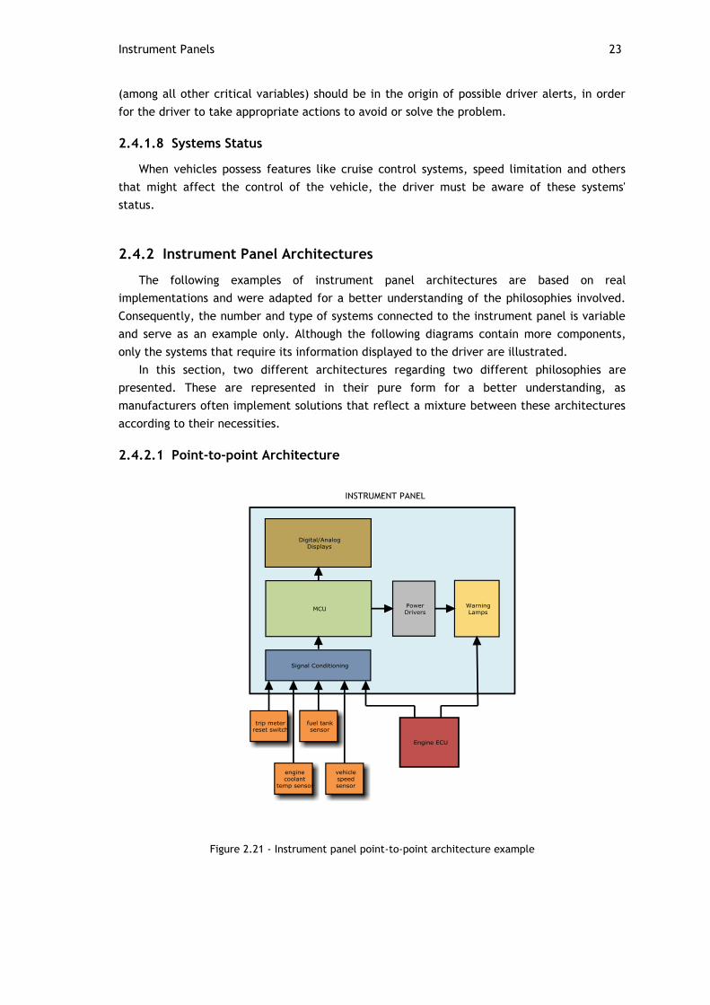
Figure 2.21 - Instrument panel point-to-point architecture example

24 In-Vehicle systems
The philosophy behind this architecture consists in hardwiring all the sensors whose
variables are to be displayed to the instrument panel ECU. Sensor acquisition is performed by
the instrument panel ECU, which controls digital displays, gauges and warning lamps
according to the values provided by the sensors. For instance, the engine ECU provides the
crankshaft sensor output to the instrument panel ECU so the value of RPM can be computed
and displayed.
Warning lamps can be directly actuated by the sources of information. Systems like the
supplemental restraint system, ABS, TCS, ESC, lighting systems among others, are commonly
hardwired to their respective warning lamps, which are activated upon activity or diagnostic
reasons. Warning lamps can also be actuated by the instrument panel ECU, when the input
signal provided by the sensor is not in the form of an on/off state and needs to be computed.
As an example, the connection between the engine coolant temperature sensor and the
instrument panel ECU enables the instrument panel MCU to analyze the engine coolant
temperature and actuate the warning lamps accordingly.
2.4.2.2 Networked Architecture
Figure 2.22 - Instrument panel networked architecture example

Steering Systems 25
The philosophy inherent to the architecture described on Figure 2.22 consists on
integrating the instrument panel ECU in a network connection with the sources of
information.
Two different types of networks are connected to the instrument panel ECU. The first, as
seen on the left part of Figure 2.22 is a high speed network where the engine ECU, brake ECU
and all the dynamic controllers of the vehicle are connected. The second network at the right
part of Figure 2.22 is a low speed network where components mainly belonging to the body
domain are connected. Just like it was referred on the previous architecture, controllers are
directly connected to the lamps as necessary.
The fuel level sensor, lighting switches and others whose values are not required by any
ECUs are computed by a multifunction ECU, which transmits its values over the network to
the instrument panel.
Variables of interest which have to be displayed and are produced within an ECU are
transmitted over the network to the instrument panel ECU. As an example, the crankshaft
position sensor is required by the engine ECU as the value of RPM is required for controlling
the engine. RPM is computed on the engine control ECU and sent over network so it can be
displayed to the driver.
This solution has many advantages comparing to the architecture demonstrated on Section
2.4.2.1:
1 . The number and complexity of wiring is drastically reduced
2 . The number of elements that may be connected with the instrument panel is only
limited by the type of network
3 . The complexity of the information that is displayed is higher
4 . The flexibility is higher, as the information to display is not dependent on the
number and type of interfaces present on the instrument panel controller.
By integrating the instrument panel ECU in a network with other systems, the ECU can
capture messages that are being traded between other systems. For instance, when loss of
traction is detected by the TCS, a message is transmitted by the TCS to the motor ECU to
reduce torque. The instrument panel ECU can capture this message and display the TCS
activity to the driver. In this way, network load and computational efforts are optimized.
Additional systems can be integrated by simply connecting them to the corresponding
network. Extra sensors that are required for displaying information to the driver can be
connected to multifunction ECUs that are connected to the network.
2.5 Steering Systems
The steering system is responsible for transforming the driver's steering intentions into the
actual change of vehicle direction. Steering systems have evolved from rather simple
mechanical systems to sophisticated intelligent systems that ease the driving, provide more
comfort and offer more security.
Steering systems started as purely mechanical systems in which no assistance was
provided to aid the driver in steering the wheels. In these systems the driver was the unique
source of the force required for overcoming the friction coefficient between the surface and
the tires. When the vehicle is stopped or moving slowly, the effort demanded to the driver for

26 In-Vehicle systems
steering the wheels can cause the driving experience to be quite unpleasant. The heavier a
vehicle is or the largest its tires are, the more this issue is aggravated.
This situation was later overcame by power steering systems, which are available in the
vast majority of vehicles sold nowadays and consist on mechanisms to assist the driver in
turning the wheels by amplifying the driver's steering torque inputs [19]. Power steering
systems exist mainly in three different kinds: hydraulic, hybrid i.e., a mixture between
hydraulic and electric, and electric.
These systems allowed that heavier vehicles or equipped with wider tires could be easily
maneuvered, despite the higher frictional forces associated with these characteristics. The
mechanical details of such systems are not in the scope of this document, but a simple
explanation of each these systems will aid the understanding of the factors and issues
involved later in this section.
The last trend in steering systems are the steer-by-wire systems, in which on the contrary
of other systems mentioned above, is based on the removal of all mechanical connections
between the steering inputs and the steering actuators. Steer-by-wire concepts are described
later on Chapter 4.
Four wheel steering is another concept whose popularity is gaining ground, and
therefore is also referred in this section.
2.5.1 Hydraulic Power Steering
In hydraulic power steering systems, the assisting force is provided by pressurized fluids.
Hydraulic fluid pressure is controlled by a pump which is mechanically coupled with the
engine. Therefore, the rotation speed of the pump's rotor depends on engine speed. Figure
2.23 and Figure 2.24 illustrates a hydraulic power steering system applied in a rack-and-
pinion configuration.
Figure 2.23 - Hydraulic power steering system applied to a rack-and-pinion configuration [20]
Steering Systems 27
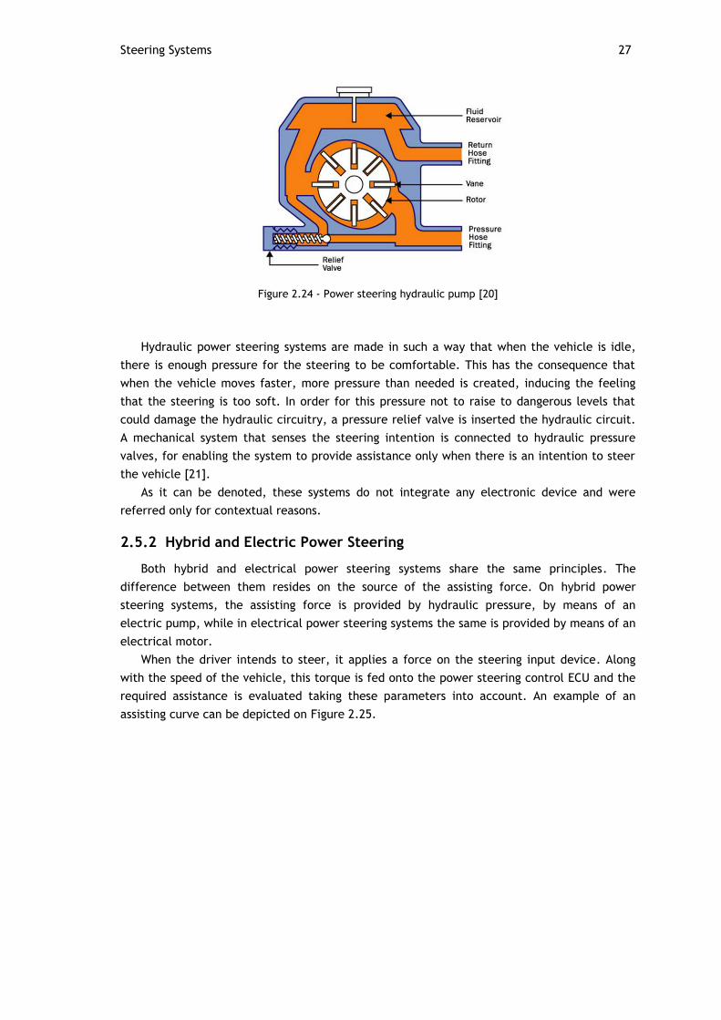
Figure 2.24 - Power steering hydraulic pump [20]
Hydraulic power steering systems are made in such a way that when the vehicle is idle,
there is enough pressure for the steering to be comfortable. This has the consequence that
when the vehicle moves faster, more pressure than needed is created, inducing the feeling
that the steering is too soft. In order for this pressure not to raise to dangerous levels that
could damage the hydraulic circuitry, a pressure relief valve is inserted the hydraulic circuit.
A mechanical system that senses the steering intention is connected to hydraulic pressure
valves, for enabling the system to provide assistance only when there is an intention to steer
the vehicle [21].
As it can be denoted, these systems do not integrate any electronic device and were
referred only for contextual reasons.
2.5.2 Hybrid and Electric Power Steering
Both hybrid and electrical power steering systems share the same principles. The
difference between them resides on the source of the assisting force. On hybrid power
steering systems, the assisting force is provided by hydraulic pressure, by means of an
electric pump, while in electrical power steering systems the same is provided by means of an
electrical motor.
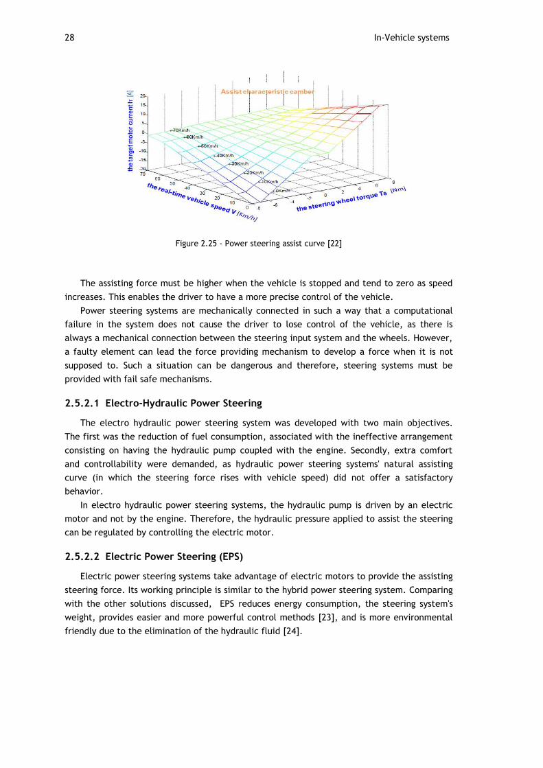
When the driver intends to steer, it applies a force on the steering input device. Along
with the speed of the vehicle, this torque is fed onto the power steering control ECU and the
required assistance is evaluated taking these parameters into account. An example of an
assisting curve can be depicted on Figure 2.25.
28 In-Vehicle systems
Figure 2.25 - Power steering assist curve [22]
The assisting force must be higher when the vehicle is stopped and tend to zero as speed
increases. This enables the driver to have a more precise control of the vehicle.
Power steering systems are mechanically connected in such a way that a computational
failure in the system does not cause the driver to lose control of the vehicle, as there is
always a mechanical connection between the steering input system and the wheels. However,
a faulty element can lead the force providing mechanism to develop a force when it is not
supposed to. Such a situation can be dangerous and therefore, steering systems must be
provided with fail safe mechanisms.
2.5.2.1 Electro-Hydraulic Power Steering
The electro hydraulic power steering system was developed with two main objectives.
The first was the reduction of fuel consumption, associated with the ineffective arrangement
consisting on having the hydraulic pump coupled with the engine. Secondly, extra comfort
and controllability were demanded, as hydraulic power steering systems' natural assisting
curve (in which the steering force rises with vehicle speed) did not offer a satisfactory
behavior.
In electro hydraulic power steering systems, the hydraulic pump is driven by an electric
motor and not by the engine. Therefore, the hydraulic pressure applied to assist the steering
can be regulated by controlling the electric motor.
2.5.2.2 Electric Power Steering (EPS)
Electric power steering systems take advantage of electric motors to provide the assisting
steering force. Its working principle is similar to the hybrid power steering system. Comparing
with the other solutions discussed, EPS reduces energy consumption, the steering system's
weight, provides easier and more powerful control methods [23], and is more environmental
friendly due to the elimination of the hydraulic fluid [24].

Steering Systems 29
Figure 2.26 - Electric power steering [24]
2.5.3 Power Steering Architecture
In Figure 2.27 the architecture of a basic power steering architecture can be observed.
Although only the basic sensors are represented, other variables can be taken in account to
enhance the performance of the power steering system such as a steering angle sensor,
steering speed, lateral acceleration, motor temperature among others.
Figure 2.27 - Power steering architecture
Vehicle speed is either obtained by connecting the vehicle speed sensor to power steering
MCU or by means of a network connection between the power steering control unit and the
motor or brake ECUs.
The power steering ECU is commonly connected to the instrument panel ECU so that
diagnostic data can be exchanged. The failure of the power steering system can have
catastrophic consequences. Therefore the power steering control unit is commonly suited
with fault detection mechanisms which de-energize the steering actuators in case of
computational failure.

30 In-Vehicle systems
2.5.4 Four Wheel Steering (4WS)
Ackerman driving is the driving configuration of cars and 4x4 motorcycles. It consists of
two wheels that do not steer in the rear and two wheels that steer in the front. Ackerman's
principle relies on intersecting at all times the axis of all of the wheels in one point. In case
this intersection is not observed, slippage of the wheels occurs [25].
The point where the axis of all wheels intersect is denominated the instantaneous point of
curvature. Therefore, as it can be observed by Figure 2.28, inner wheels turn sharper than
outer wheels in respect to the curve.
Figure 2.28 : Ackerman drive geometry
Four wheel steering can reduce the instantaneous point of curvature (21% referred on
[26]) and provide more mobility to a vehicle. This is useful when the vehicle is moving slowly,
so that maneuvers can be made more easily. 4WS enables the reduction of the instantaneous
center of curvature by steering the rear wheels in the opposite direction than the front
wheels.
Figure 2.29 : 4WD decrease of turning radius
At high speeds, 4WS increases vehicle stability [27]. To achieve that, rear wheels steer in
the same direction as the front wheels.
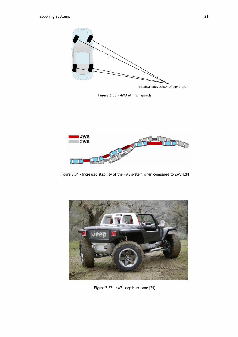
Steering Systems 31
Figure 2.30 - 4WD at high speeds
Figure 2.31 - Increased stability of the 4WS system when compared to 2WS [28]
Figure 2.32 - 4WS Jeep Hurricane [29]

32 In-Vehicle systems
2.5.4.1 4WS architecture
The four wheel steering architecture is depicted on Figure 2.33. The 4WS MCU analyses
the steering wheel position and vehicle speed. After computing the desired rear wheel
position, rear wheels are orientated by means of an electric motor.
The steering wheel position can be shared by the power steering ECU by means of a
network connection or the steering wheel position sensor can be directly connected to the
4WS control unit.
Figure 2.33 - 4WS architecture
2.6 Exterior Lighting Systems
Lights have the task of illuminating the path to the driver and to assist in evidencing the
vehicle's shape, so other drivers are aware of it with the minimum possible effort. According
to an issued report by the United States department of transportation, vision contributes with
90% of the information needed to the driver, hence the fact that most of the accidents
happen at night, or during bad visibility periods due to poor weather conditions such as rain
or fog.
The types of lights that shall be present in a vehicle and the situations that their use is
mandatory varies from country to country. The various types of lights that are commonly
found in vehicles are:
1. Low beam - Cruising lights that do not obfuscate other drivers and provide
enough illumination for night driving
2. High beam - Intense lights that can only be used when the vehicle is not crossing
with other vehicles as it produces considerable amounts of glare
3. Daytime running lamps - Mandatory in some countries. Low intensity lights that
enable a better perception of the vehicle
4. Directional indicators - Blinking lights that indicate other drivers the intention in
changing direction.
5. Brake lights - Give other drivers the information that the vehicle is braking
6. Reverse lights - Provide other drivers with the indication that the vehicle is
driving on reverse
Exterior Lighting Systems 33
7. Fog lights - Provide better illumination on foggy environments
Lighting systems have been suffering a deep evolution in the past years. The lighting
system is changing from being a static system, to a dynamic system that actively contributes
to safety and comfort.
In this section, several emergent features regarding lighting systems are presented. The
names in which these systems are known vary from manufacturer to manufacturer.
Therefore, adaptations or mixes between system names are used.
This section would not be complete without a brief comment on light-emitting-diode
(LED) lighting systems, due to their potential of becoming the most widely used lighting
solution. LED lighting systems offer space reduction, less energy consumption, longer lasting
life and faster rise to full intensity than standard bulbs. Due to the massification of its
production, prices are dropping which means that it is expected that in the future the vast
majority of the cars will run on led lights. Despite of what can be thought at first sight, the
task of implementing LED lights on a vehicle is not trivial, due to the fact that in combustion
engine vehicles the battery voltage can vary between 9 to 16 Volt. Therefore, the traditional
way of driving a LED which consists in connecting a series resistor is not applicable, since
variations in voltage cause variations in the LEDs' currents, which in turn will cause a variation
on light intensity. Instead, buck-boost controllers are commonly implemented, which typically
requires a microcontroller to generate the duty cycle signal and perform monitoring on LED's
current so it doesn't exceed its rated value.
2.6.1 Automatic Lighting
Automatic lighting systems activate low beam lights upon detection of darkness or rain.
This is achieved by sensing ambient light and rain through specific sensors that are connected
to the lights ECU.
2.6.2 Fused Light Detection
The fused light detection system operates by monitoring the current fed to each bulb.
When the lights ECU sends a signal to activate a certain bulb and no current flowing to it, it
may indicate that the bulb is fused. In case of LED lights are used in series, an increase in the
LED's current may also indicate led failure.
2.6.3 Dynamic Headlight Range Adjustment
Vehicle dynamic motion on the vertical axis causes the range of the headlights to change.
When the vehicle is tilting forward, the range is reduced thus reducing the driver's sight.
Upon forward tilt, the range is augmented, in which glare can be induced and blind other
drivers. Vehicle front and rear tilting happens for several reasons: heavy load on the rear or
front of the vehicle, bumps on the road or upon fast accelerations or decelerations.
The objective of the dynamic headlight range adjustment system is to grant that the
vertical motion of the vehicle does not affect the headlights range.
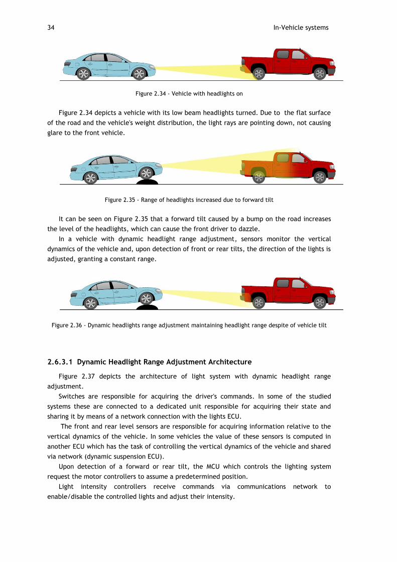
34 In-Vehicle systems
Figure 2.34 - Vehicle with headlights on
Figure 2.34 depicts a vehicle with its low beam headlights turned. Due to the flat surface
of the road and the vehicle's weight distribution, the light rays are pointing down, not causing
glare to the front vehicle.
Figure 2.35 - Range of headlights increased due to forward tilt
It can be seen on Figure 2.35 that a forward tilt caused by a bump on the road increases
the level of the headlights, which can cause the front driver to dazzle.
In a vehicle with dynamic headlight range adjustment, sensors monitor the vertical
dynamics of the vehicle and, upon detection of front or rear tilts, the direction of the lights is
adjusted, granting a constant range.
Figure 2.36 - Dynamic headlights range adjustment maintaining headlight range despite of vehicle tilt
2.6.3.1 Dynamic Headlight Range Adjustment Architecture
Figure 2.37 depicts the architecture of light system with dynamic headlight range
adjustment.
Switches are responsible for acquiring the driver's commands. In some of the studied
systems these are connected to a dedicated unit responsible for acquiring their state and
sharing it by means of a network connection with the lights ECU.
The front and rear level sensors are responsible for acquiring information relative to the
vertical dynamics of the vehicle. In some vehicles the value of these sensors is computed in
another ECU which has the task of controlling the vertical dynamics of the vehicle and shared
via network (dynamic suspension ECU).
Upon detection of a forward or rear tilt, the MCU which controls the lighting system
request the motor controllers to assume a predetermined position.
Light intensity controllers receive commands via communications network to
enable/disable the controlled lights and adjust their intensity.
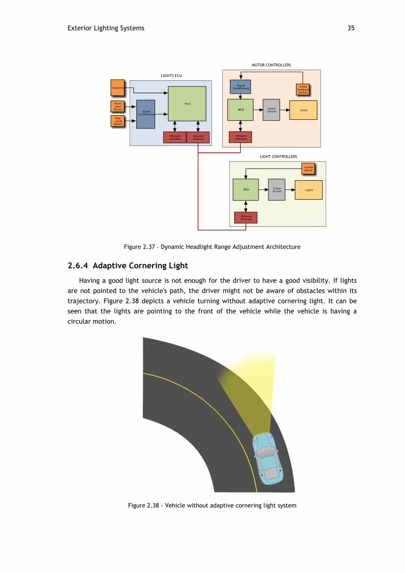
Exterior Lighting Systems 35
Figure 2.37 - Dynamic Headlight Range Adjustment Architecture
2.6.4 Adaptive Cornering Light
Having a good light source is not enough for the driver to have a good visibility. If lights
are not pointed to the vehicle's path, the driver might not be aware of obstacles within its
trajectory. Figure 2.38 depicts a vehicle turning without adaptive cornering light. It can be
seen that the lights are pointing to the front of the vehicle while the vehicle is having a
circular motion.
Figure 2.38 - Vehicle without adaptive cornering light system

36 In-Vehicle systems
Figure 2.39 illustrates a vehicle equipped with the adaptive cornering light system. The
lights ECU analyzes vehicle dynamics and calculates where the lights should be pointed at.
Electric motors adjust the determined swivel angle so the lights are always pointed to the
direction of motion of the vehicle.
Figure 2.39 - Vehicle equipped with adaptive light cornering system
The swivel angle is determined based on three variables: vehicle speed, steering wheel
position and yaw rate. The steering wheel position is used to compute the swivel angle for
low speeds (typically below 40 Km/h), while for high speeds both the vehicle speed sensor
and yaw rate are used to compute the swivel angle.
2.6.4.1 Adaptive Cornering Light System's Architecture
An architecture able of implementing the adaptive cornering light system is similar to that
given on Figure 2.37, with the addition of motors and their respective controllers to adjust
the horizontal position of the lights. The value the yaw sensor is typically shared by the brake
ECU while the steering wheel angle is typically shared by the power steering ECU.
2.6.5 Camera Based Lighting Systems
This section provides a brief description of the upcoming (and already available in some
high end models) lighting systems that provide extra safety and comfort. All of the systems
described in this section rely on image analysis.
2.6.5.1 High Beam Assist
Several studies point out that high beam lights are rarely used even in situations when
these do not cause other drivers to glare. This can be seen as a waste of illumination
potential as high beam lights illuminate much further ahead, giving extra time for the driver
to perceive potential dangerous situations and react accordingly.

Exterior Lighting Systems 37
The high beam assist system captures images of the surrounding environment such as road
lights, headlights and rear lights of other vehicles and decides whether high beam lights are
required or not. In case that the road light is sufficient or in case other vehicles are in risk of
perceiving glare, high beam lights are disabled.
2.6.5.2 Adaptive Cutoff Line
Adaptive cut-off line system can be seen as an upgrade of the high beam assist. It has the
task of optimizing the driver's visibility. A camera analyses front vehicles, and light angle is
adapted so the cut-off line ends as far as possible, while not blinding the front vehicle's
driver. If the system does not detect any drivers ahead, low beam lights are switched to high
beam. Figure 2.40 illustrates an adaptive cut-off regulating the cut-off line according to the
front vehicle.
Figure 2.40 - Adaptive cutoff line
2.6.5.3 Glare Free Systems
Glare free systems are another update of the high beam assist system. With it, vehicle's
can drive with high beam lights on without affecting other drivers. Glare free systems analyze
the position of other vehicles and block parts of the light that can disturb other drivers.
Figure 2.41 - Glare free system

38 In-Vehicle systems
In Figure 2.41 is represented a vehicle with a glare free system that controls a multiple
LED light source. According to the information acquired through the analysis of camera
images, the LED modules that have its light rays targeting other vehicles are pointed in a
direction in which they do not induce glare on other drivers.
2.6.5.4 Marking Light Systems
While drivers might be with their attention focused on several light sources, some
situations might happen that require the driver's sudden attention. Events such as a
pedestrian crossing or an incoming vehicle in a crossroad might not be flashy enough to get
the driver's attention. Marking light systems have the task of illuminating objects that appear
suddenly, thus shifting the driver's attention for situations that might impose danger.
Figure 2.42 - Marking light system evidencing a pedestrian
Figure 2.42 illustrates a light marking system in action. While the vehicle is driving
straight ahead, a pedestrian (represented by a red circle) is standing near the crosswalk. The
marking light system identifies this situation and illuminates the pedestrian so the driver can
be aware of it.
2.6.5.5 Night Vision Systems
Night vision systems take advantage of infra red light to capture what the human eye
cannot. In a vehicle equipped with a night vision system, an infrared light source emits
infrared light, which hits objects and reflects back to an infrared camera that is connected to
an image analysis system and a monitor. The image analysis system performs routines in order
to detect potential dangerous situations, and upon detection of these engages actions so the
driver can be aware of it.
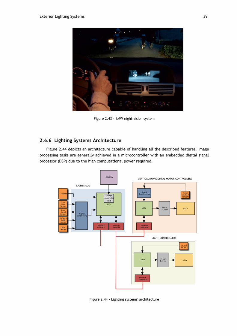
Exterior Lighting Systems 39
Figure 2.43 - BMW night vision system
2.6.6 Lighting Systems Architecture
Figure 2.44 depicts an architecture capable of handling all the described features. Image
processing tasks are generally achieved in a microcontroller with an embedded digital signal
processor (DSP) due to the high computational power required.
Figure 2.44 - Lighting systems' architecture
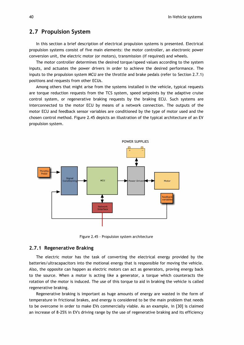
40 In-Vehicle systems
2.7 Propulsion System
In this section a brief description of electrical propulsion systems is presented. Electrical
propulsion systems consist of five main elements: the motor controller, an electronic power
conversion unit, the electric motor (or motors), transmission (if required) and wheels.
The motor controller determines the desired torque/speed values according to the system
inputs, and actuates the power drivers in order to achieve the desired performance. The
inputs to the propulsion system MCU are the throttle and brake pedals (refer to Section 2.7.1)
positions and requests from other ECUs.
Among others that might arise from the systems installed in the vehicle, typical requests
are torque reduction requests from the TCS system, speed setpoints by the adaptive cruise
control system, or regenerative braking requests by the braking ECU. Such systems are
interconnected to the motor ECU by means of a network connection. The outputs of the
motor ECU and feedback sensor variables are conditioned by the type of motor used and the
chosen control method. Figure 2.45 depicts an illustration of the typical architecture of an EV
propulsion system.
Figure 2.45 - Propulsion system architecture
2.7.1 Regenerative Braking
The electric motor has the task of converting the electrical energy provided by the
batteries/ultracapacitors into the motional energy that is responsible for moving the vehicle.
Also, the opposite can happen as electric motors can act as generators, proving energy back
to the source. When a motor is acting like a generator, a torque which counteracts the
rotation of the motor is induced. The use of this torque to aid in braking the vehicle is called
regenerative braking.
Regenerative braking is important as huge amounts of energy are wasted in the form of
temperature in frictional brakes, and energy is considered to be the main problem that needs
to be overcome in order to make EVs commercially viable. As an example, in [30] is claimed
an increase of 8-25% in EV's driving range by the use of regenerative braking and its efficiency
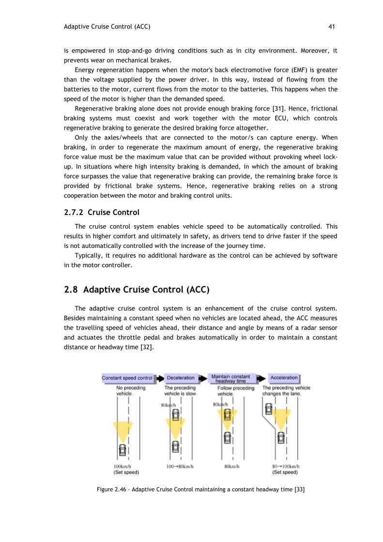
Adaptive Cruise Control (ACC) 41
is empowered in stop-and-go driving conditions such as in city environment. Moreover, it
prevents wear on mechanical brakes.
Energy regeneration happens when the motor's back electromotive force (EMF) is greater
than the voltage supplied by the power driver. In this way, instead of flowing from the
batteries to the motor, current flows from the motor to the batteries. This happens when the
speed of the motor is higher than the demanded speed.
Regenerative braking alone does not provide enough braking force [31]. Hence, frictional
braking systems must coexist and work together with the motor ECU, which controls
regenerative braking to generate the desired braking force altogether.
Only the axles/wheels that are connected to the motor/s can capture energy. When
braking, in order to regenerate the maximum amount of energy, the regenerative braking
force value must be the maximum value that can be provided without provoking wheel lock-
up. In situations where high intensity braking is demanded, in which the amount of braking
force surpasses the value that regenerative braking can provide, the remaining brake force is
provided by frictional brake systems. Hence, regenerative braking relies on a strong
cooperation between the motor and braking control units.
2.7.2 Cruise Control
The cruise control system enables vehicle speed to be automatically controlled. This
results in higher comfort and ultimately in safety, as drivers tend to drive faster if the speed
is not automatically controlled with the increase of the journey time.
Typically, it requires no additional hardware as the control can be achieved by software
in the motor controller.
2.8 Adaptive Cruise Control (ACC)
The adaptive cruise control system is an enhancement of the cruise control system.
Besides maintaining a constant speed when no vehicles are located ahead, the ACC measures
the travelling speed of vehicles ahead, their distance and angle by means of a radar sensor
and actuates the throttle pedal and brakes automatically in order to maintain a constant
distance or headway time [32].
Figure 2.46 - Adaptive Cruise Control maintaining a constant headway time [33]

42 In-Vehicle systems
The adaptive cruise control is a complex system which relies not only on the radar sensor
but also in values provided by other ECUs, as detecting objects alone is not enough for
performing a correct evaluation of the situation.
The objects that must be considered for the adaptive cruise control operation are the
ones traveling in the same lane as the vehicle. Situations where the vehicle is turning, and
consequently in which front vehicles are also turning, demand the cooperation between
several control units, which provide the values of interest variables such as speed of the
vehicle, steering angle and yaw momentum that enable the ACC system to evaluate the
situation. Such variables are also used for performing calculations when the vehicle is
changing lanes, as the ACC is required to track objects on the lane in which the vehicle is
moving to.

43
Chapter 3
In-Vehicle Networks
3.1 Introduction
This section presents the major networking solutions used by manufacturers to
interconnect the systems referred in the previous chapter.
The first computational based features that were implemented in the automotive industry
relied on centralized architectures, consisting of a set of sensors and actuators connected to
a microcontroller.
Due to the low interaction between ECUs, in the cases that data exchanges were
required, this would be achieved by means of point-to-point connections between the
corresponding ECUs. Upon appearance of more complex features that demanded a strong
cooperation between multiple ECUs, allied to a significant increase in the number of sensors
and actuators connected to ECUs, the huge number of wires present in vehicles started to
compromise their overall competitiveness: cost, complexity, reliability and weight were the
major concerns [34].
Soon, the automotive market started to demand solutions that that could enable multiple
ECUs to transmit data over the same transmission medium.
Figure 3.1 - Reduction of number of wiring by means of interconnecting ECUs in a network

44 In-Vehicle Networks
Due to their importance in the automotive market, the controller area network (CAN), the
local interconnect network (LIN) and Flexray are introduced with further detail.
3.2 Network Requirements for the Different Automotive Domains
The different vehicle domains discussed in Chapter 2 impose different requirements on
the networks that support their operation. In [7], the following requirements are considered:
Fault tolerance - the ability of the communication network to withstand
behaviors that are not congruent with its specification. Fault tolerant networks
embed a series of mechanisms such as bus guardians, which prevent nodes to
transmit in time frames that are reserved for other nodes, and redundant
hardware and software which provide error detection, confinement and recovery
Predictability - the ability of a communication system to know when messages
will be transmitted. Predictable communication systems are usually achieved by
enforcing messages to be sent at predefined time instants or time intervals
Bandwidth - the data rate supported by the network system
Flexibility - the ability of the network to cope with both event and time-triggered
messages, various scenarios of network load and network scalability
Security - the ability to prevent unauthorized access
Table 3.1 presents the automotive domains referred on Chapter 2 and their major
requirements
Table 3.1 - Automotive domains and their major requirements. Based in [7]
Subsystem Fault
tolerance
Predictability Bandwidth Flexibility Security
Powertrain YES YES HIGH NO NO
Chassis YES YES HIGH SOME NO
Body SOME SOME MEDIUM SOME NO
Passive Safety YES YES HIGH NO NO
HMI/Infotainment NO SOME HIGH YES SOME
Telematics NO SOME MEDIUM YES YES

In-vehicle Network Classifications 45
3.3 In-vehicle Network Classifications
The Society for Automotive Engineers (SAE) classifies the types of networks which are
commonly found in vehicles according to their bitrates into four different classes that are
described in this section.
3.3.1 Class A Networks
Class A networks are typically low cost networks characterized by transmission rates lower
than 10 Kbps, that are used to transmit control data in the body domain [34]. Systems
integrated in the body domain such as door control, climate control, seat adjustment among
others, do not impose strict timing requirements or high transmission bitrates, as
communications are mainly event-triggered. Examples of class A networks are the local
interconnect network (LIN) and time-triggered protocol A (TTP/A).
3.3.2 Class B Networks
Class B networks operate at bitrates ranging from 10 to 125 Kbps and are mainly used to
support data exchanges between ECUs to reduce the number of sensors by sharing
information [6]. Low-speed CAN and J1850 are examples of class B networks.
3.3.3 Class C Networks
Class C networks are characterized by having transmission rates from 125 to 1 Mbps, and
have been used over the years to integrate systems from the powertrain and chassis domain.
An example of a class C network is the high-speed CAN.
3.3.4 Class D Networks
Class D networks operate with bitrates higher than 1 Mbps and are oriented for advanced
powertrain and chassis systems, supplemental restraint systems, drive-by-wire systems and
multimedia data [34].
Examples of class D networks are Byteflight, time-triggered protocol C (TTP/C), Flexray,
Media Oriented Systems Transport (MOST) and FireWire (IEEE 1394).
46 In-Vehicle Networks
3.4 Communication Networks for the Automotive Industry
To overcome the perceived limitations of the I2C and D2B networks which were used in
automobiles [35], Bosch started the development of the network that would revolutionize the
hole automotive industry in 1983: the controller area network (CAN). The first specifications
were publicly presented in 1986 at the society of automotive engineers congress, and the
protocol was widely implemented in the beginning of the 90's.
CAN was designed to be a high performance communication system to support the
operation of the powertrain and chassis domain, gifted with powerful arbitration, fault
detection, error confinement mechanisms, and bit rates ranging from 10 Kbps up to 1 Mbps. It
is also used as the communication protocol for systems belonging to the body domain, serving
as the backbone for LIN, a low cost network targeted for the requirements of the body
domain. Due to its success, CAN became an international standard: ISO 11898 [36].
As new generations of vehicles started to carry more sophisticated electronic systems,
along with the upcoming drive-by-wire systems, higher bit rates, strict determinism and more
reliability started being demanded.
The necessity for higher bitrates is a consequence of the increase in the number,
complexity and the level of interaction between the different systems within a vehicle. Bit
rates up to 10 Mbps are expected to be required [37], as opposed from the 1 Mbps top bitrate
offered by CAN.
The upcoming drive-by-wire systems and other critical features require levels of
determinism which CAN is unable to provide as an event triggered protocol [37]. First of all,
due to the fact that nodes are allowed to produce messages asynchronously, the number of
collisions a frame faces with high priority frames is unknown. High priority frames with no
errors might be sent by a faulty node continuously, giving lower priority frames no chance to
be transmitted (the babbling idiot problem). Such situations can lead to the miss of deadlines
of hard real time tasks as well as dangerous jitters that affect control algorithms.
Furthermore, CAN does not allow a bus guardian to be implemented as a consequence of the
uncertainty of when a message will be transmitted. Consequently, erroneous nodes
outputting high level priority messages cannot be disabled, thus blocking the entire network.
The reliability required by safety critical systems in vehicles demands the support of a
redundant transmission medium, as critical systems cannot rely on single points of failure. On
its specification, CAN does not address the implementation of redundant transmission
mechanisms.
Several attempts were made to overcome CAN's referred limitations. The most popular
protocols that were developed in order to overcome CAN limitations were TTCAN, Byteflight
and TTP [37].
Exhaustive technical analysis were performed by a group of automotive companies to
discover whether any of these protocols was capable of meeting all the requirements for the
upcoming generation of vehicles. It was proved that none of them could fulfill those
requirements, which led to the development of a new communications network called Flexray
[38]. Flexray is now starting to be adopted but its cost is still considered to be high and
therefore it is still used in conjunction with CAN.
TTEthernet is also able to provide the deterministic behavior and fault tolerance
mechanisms as Flexray, with the addition of supporting bitrates up to 10Gb/s. Given its
potential, TTEthernet is discussed in Section 3.8.
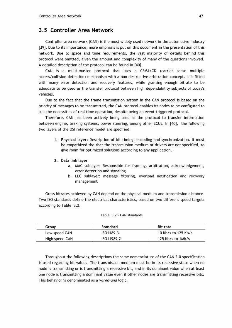
Controller Area Network 47
3.5 Controller Area Network
Controller area network (CAN) is the most widely used network in the automotive industry
[39]. Due to its importance, more emphasis is put on this document in the presentation of this
network. Due to space and time requirements, the vast majority of details behind this
protocol were omitted, given the amount and complexity of many of the questions involved.
A detailed description of the protocol can be found in [40].
CAN is a multi-master protocol that uses a CSMA/CD (carrier sense multiple
access/collision detection) mechanism with a non destructive arbitration concept. It is fitted
with many error detection and recovery features, while granting enough bitrate to be
adequate to be used as the transfer protocol between high dependability subjects of today's
vehicles.
Due to the fact that the frame transmission system in the CAN protocol is based on the
priority of messages to be transmitted, the CAN protocol enables its nodes to be configured to
suit the necessities of real time operation, despite being an event-triggered protocol.
Therefore, CAN has been actively being used as the protocol to transfer information
between engine, braking systems, power steering, among other ECUs. In [40], the following
two layers of the OSI reference model are specified:
1. Physical layer: Description of bit timing, encoding and synchronization. It must
be empathized the that the transmission medium or drivers are not specified, to
give room for optimized solutions according to any application.
2. Data link layer
a. MAC sublayer: Responsible for framing, arbitration, acknowledgement,
error detection and signaling.
b. LLC sublayer: message filtering, overload notification and recovery
management
Gross bitrates achieved by CAN depend on the physical medium and transmission distance.
Two ISO standards define the electrical characteristics, based on two different speed targets
according to Table 3.2.
Table 3.2 - CAN standards
Group Standard Bit rate
Low speed CAN ISO1189-3 10 Kb/s to 125 Kb/s
High speed CAN ISO11989-2 125 Kb/s to 1Mb/s
Throughout the following descriptions the same nomenclature of the CAN 2.0 specification
is used regarding bit values. The transmission medium must be in its recessive state when no
node is transmitting or is transmitting a recessive bit, and in its dominant value when at least
one node is transmitting a dominant value even if other nodes are transmitting recessive bits.
This behavior is denominated as a wired-and logic.

48 In-Vehicle Networks
3.5.1 CAN Nodes Interaction Model
Flexibility was one of the major concerns upon the design of the CAN specifications.
Hence, to outfit each node with a physical address and route messages with the basis of that
address would not provide the desired elasticity, as changing the network configuration would
require the reconfiguration of all of the nodes.
Therefore, CAN nodes transmit messages in a publisher-subscriber fashion. This implies
that all messages are broadcasted into the network. Upon reception of a message, each node
decides whether the message is to be processed or not. This decision is based on the message
identifier, placed on the arbitration field of each frame.
3.5.2 Bus Access
In a multimaster network like CAN each node is free to start the transmission of a frame.
However, multiple nodes can start transferring data at the same time. CAN frames are
provided with a specific field (the arbitration field) for handling arbitration between
transmitting nodes.
During the arbitration phase each sender compares the value present in the transmission
medium with the value that it has transmitted. In case these values do not match, which
uniquely happens in the case where the node has outputted a recessive level and a dominant
level was observed in the line, the sender stops transmitting, as this implies that other node
is sending a message with higher priority. It is important to note that the presence of multiple
senders at the same time in the same network does not destroy the content of the higher
priority frame. This form of arbitration is called non-destructive.
Figure 3.2 depicts an example of the arbitration procedure between three emitting
stations.
Figure 3.2 - CAN arbitration procedure in a wired-and bus [38]
The arbitration procedure implies that in a wired-and bus, in which the logical one
assumes the zero bus value, and a logical zero assumes the one bus value, the lesser a
message identifier is, the higher priority is granted to the frame.
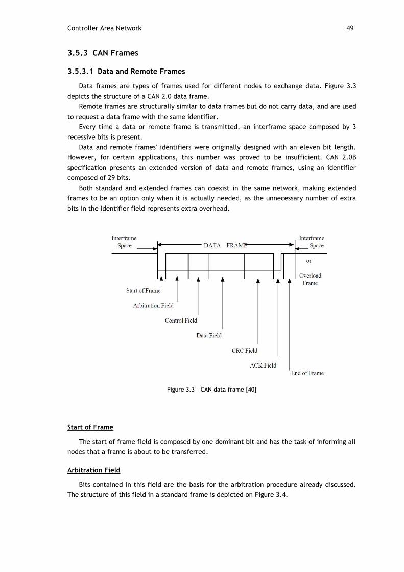
Controller Area Network 49
3.5.3 CAN Frames
3.5.3.1 Data and Remote Frames
Data frames are types of frames used for different nodes to exchange data. Figure 3.3
depicts the structure of a CAN 2.0 data frame.
Remote frames are structurally similar to data frames but do not carry data, and are used
to request a data frame with the same identifier.
Every time a data or remote frame is transmitted, an interframe space composed by 3
recessive bits is present.
Data and remote frames' identifiers were originally designed with an eleven bit length.
However, for certain applications, this number was proved to be insufficient. CAN 2.0B
specification presents an extended version of data and remote frames, using an identifier
composed of 29 bits.
Both standard and extended frames can coexist in the same network, making extended
frames to be an option only when it is actually needed, as the unnecessary number of extra
bits in the identifier field represents extra overhead.
Figure 3.3 - CAN data frame [40]
Start of Frame
The start of frame field is composed by one dominant bit and has the task of informing all
nodes that a frame is about to be transferred.
Arbitration Field
Bits contained in this field are the basis for the arbitration procedure already discussed.
The structure of this field in a standard frame is depicted on Figure 3.4.

50 In-Vehicle Networks
Figure 3.4 - Standard format of CAN frame arbitration and control fields [40]
In the standard frame format, the arbitration field carries the 11 bit message identifier,
plus a bit known as remote transmission request (RTR). This bit signals whether the frame is a
data or remote frame. Its value is dominant in the case of a data frame and recessive in the
case of a remote frame. This implies that data frames have priority over remote frames with
the same identifier.
The arbitration field of an extended frame is illustrated on Figure 3.5.
Figure 3.5 - Extended format of CAN arbitration and control fields [40]
As it was already mentioned, the identifier field of an extended frame is composed of 29
bits. The first 11 bits are denominated the base ID while the remaining bits of the identifier
are denominate the extended ID.
The base and the extended ID bits are separated by two bits: the substitute remote
request (SRR) and the identifier extension bit (IDE).
The SRR is recessive in an extended frame and overlaps the RTR bit in the standard frame.
The identifier extension (IDE) bit informs whether a frame is in its extended form or not.
In the case of a standard frame this bit is dominant, while in the case of an extended frame
this bit is recessive. In this way, when two data frames with the same base ID are sent over
the network, in which one of them is in the standard format and the other in the extended
format, the standard frame will gain access to the bus.

Controller Area Network 51
Control Field
The control fields of standard and extended frames are composed of 6 bits.
Both standard and extended frames are composed of a section named data length code
(DLC) which is used to specify the number of bytes present in the data field. Due to the fact
that the maximum number of bytes in the data field is 8, the DLC is made of 4 bits.
The first two bits of the control field are different for each frame. The control field of
standard frames is composed of the IDE and a reserved bit (R0) for future uses, while the
control field of extended frames is composed of the R0 and R1 bits, both reserved for future
uses.
It should be noted that the IDE bit is present on the control field of standard frames while
in extended frames this bit is present on the arbitration field.
In both types of frames, the reserved bits are sent as dominant.
Data Field
The data field is the section where the data is carried. 8 bytes can be transferred from
the most significant bit (MSB) to the least significant bit (LSB).
Cyclic Redundancy Check Field (CRC field)
This section carries an error detection code discussed in Section 3.5.5.3.
Acknowledge Field (ACK)
The acknowledge field is similar in both standard and extended frames. It is composed of
two sections: the ACK field and the ACK delimiter. When transmitting this field, the sender
switches to listening mode, thus outputting a recessive level on the transmission medium. All
the nodes in the network which received a successful frame containing no errors output a
dominant level in the ACK field. This procedure informs the sender that the frame was
correctly received by at least one node.
End of Frame
The end of frame field consists of seven recessive bits, which indicate that the
transmission of the frame has ended.
Error Frames
Error frames are sent immediately on the next bit after the error detection. Upon
detection of CRC errors, error frames are sent on the first bit after the ACK delimiter. Error
frames have purposely a structure that violates the stuffing rule (refer to Section 3.5.5.2).
Therefore, when an error frame is sent by a node which has detected an error, this will cause
other nodes to detect a stuffing error, which will cause them to output their own error
frames.
The structure of error frames is illustrated on Figure 3.6.
Error frames are composed of an error flag and an error delimiter fields. There are two
kinds of error flags in the error frames: active and passive flags. The situations whether each
of the flags is transmitted by a particular node is related to CAN's fault confinement strategy
which is discussed in Section 3.5.6.

52 In-Vehicle Networks
Figure 3.6 - CAN error frame structure [40]
Active error frames are composed of 6 dominant bits, while passive error flags are
composed by 6 recessive bits. When a node detects a transmission error, it starts emitting its
own error flag. Therefore, the error flag segment has variable size as it might represent the
superposition of various error flags between nodes. This superposition will have the maximum
number of twelve bits, which happens in the case of a node detecting an error after a
transition from dominant to recessive, which will cause other nodes to only detect the bit
stuffing violation in the sixth bit of the error flag.
After outputting an error flag, each station transmits recessive bits.
Upon detection of a recessive bit in the transmission line, implying that all of the stations
are transmitting recessive bits, which in turn mean that all nodes have transmitted error
flags, each node transmits seven more recessive bits. Hence, the error delimiter section is
composed by eight recessive bits.
3.5.4 Overload Frames
Overload frames have the task of creating a delay between the delivery of frames so data
is not lost by an overloaded node. The structure of overload frames is similar to active error
frames and two overload frames can be sent consecutively by a particular node.
Overload frames consist of an overload flag and an overload delimiter, and are
transmitted by any node under the following circumstances:
1. In case that additional time is required to compute last operations, the overload
frame is transmitted at the first bit time of the upcoming intermission
2. Upon detection of a dominant bit at the first and second bits of intermission, or a
dominant bit at the eight bit of the error delimiter, the overload frame is transmitted
in the next bit after the dominant bit detected
Upon detection of an overload flag, each node outputs its own overload flag.
The overload delimiter operation is analogous to what was described in the error frame
section.
3.5.5 Error Detection, Processing and Management
Due to the fact that CAN serves as the path for the exchange of safety critical messages,
the protocol is equipped with several error detection mechanisms that are described in this
section.

Controller Area Network 53
3.5.5.1 Bus Monitoring
Disregarding the arbitration and acknowledge fields, when bus access has been granted to
a node, it compares the value present in the line with the value that it is outputting. In case
that these do not match, a bit error is present.
3.5.5.2 Bit Stuffing
The bit stuffing method consists in having the transmitter of a frame adding an extra bit
after the detection of five consecutive bits with the same value, whose value is the
complement of those bits.
In this way, errors in which the node's outputs stay fixed in a dominant or recessive level
are detected. Due to the fact that the CRC delimiter, ACK field and end of frame have fixed
structures, these are not stuffed.
3.5.5.3 Cyclic Redundancy Check (CRC)
The cyclic redundancy check code is the rest of the division formed by treating the stream
of bits since the start of frame until the end of the data field as a polynomial (with fifteen
zeros added to the less significant coefficients and not stuffed) by the polynomial 𝑔 𝑥 =
𝑥15 + 𝑥14 + 𝑥10 + 𝑥8 + 𝑥7 + 𝑥4 + 𝑥3 + 1 (BCH code). This value is sent on the CRC field.
Upon reception of a frame, the receiver calculates the CRC value of the received message
and compares with the received CRC value. In case that these values do not match, a
transmission error has occurred.
3.5.5.4 Message Frame Check
Transmission errors can affect the frame's structure. Hence, each node monitors messages
and checks whether incoming messages respect the frame's structure. In case this structure is
not respected an error is signaled.
3.5.5.5 Acknowledgement Field
The acknowledgment of messages serves as the confirmation that a frame was correctly
transmitted over the network (disregarding the unlikely event that an error might assume the
form of a positive acknowledge). In case that the sender does not receive any positive
acknowledgement, it can conclude that the message was not correctly transmitted and thus
outputs an error frame.
3.5.5.6 Error Frames Dispatch
Error frames dispatching is discussed in Section 3.5.3.2.
3.5.6 Fault Confinement Strategy
The CAN protocol tries to minimize the effect of erroneous nodes on the network by
confining their behavior. For this purpose, two kinds of counters are present in each node:
one for counting transmission errors and other for counting reception errors.
Every time a transmission or reception error is detected the respective counter is
incremented. On the contrary, upon successful reception or transmission the respective error
counters are decremented. The increment/decrement of counters do not follow a

54 In-Vehicle Networks
proportional rule, as errors cause the counters to be incremented by a greater value than the
decrease of its value upon detection of a successful transfer.
This provides a better perception of the fail distribution among the network as well a
more strict confinement rule. Figure 3.7 illustrates the error confinement strategy:
Figure 3.7 - Transitions between error states in CAN
If error counters are both below 128 the node is said to be on the active error state. Being
in the active error state means that the node operates normally and, upon detection of an
error, the node will output an active error flag, causing other nodes to detect this error flag.
If both counters are below 255 and at least one of the counters is above 127 the node is
said to be on the passive error state. Likewise, the node will operate normally but upon
detection of an error the node will output an error frame with a passive error flag, thus not
interfering with the rest of the network.
Nodes enter the bus off mode when transmission error counters are higher than 255. In
the bus off mode nodes are not allowed to transmit. This prevents a faulty node to block the
entire network. In this state the node is not allowed to transmit, but it monitors the network
as 128 occurrences of 11 successive recessive bits trigger the node back to the active error
state.
3.6 Flexray
Flexray is a communication system targeted for high-speed control applications in vehicles
such as advanced powertrain, chassis, and by-wire systems [41]. Flexray is able to offer bit
rates up to 10 Mbps and provides the support for dual-channel communication systems, which
can either be used to provide redundancy if the same frames are carried in both
communication channels, or double the available bandwidth, in case that the secondary
channel is used for the transmission of additional data.
Not only it does it enable bus topologies, but also other complex approaches such as
active and passive stars, and mixes between these topologies to be implemented. Examples
of topologies supported by Flexray can be found in Figure 3.8.

Flexray 55
In addition to this, Flexray is able to grant bounded latencies and jitter through the aid of
a TDMA based approach, a basic requirement for distributed control systems, while not
leaving behind the support of event driven occurrences.
Figure 3.8 - Flexray topologies [42]
3.6.1 Bus Access
Bus access within the Flexray protocol occurs taking as basis a communication cycle
where two different bus access mechanisms take place. The first mechanism occurs in a
section called the static segment and is based on the TDMA approach, able to guarantee fixed
latencies and jitter in which distributed control systems rely on. The dynamic segment is
responsible for handling events which are not periodic in its nature. The transfer of frames
within this segment is subject to a prioritizing rule based on the frame identifiers.
Figure 3.9 - Flexray communication cycle
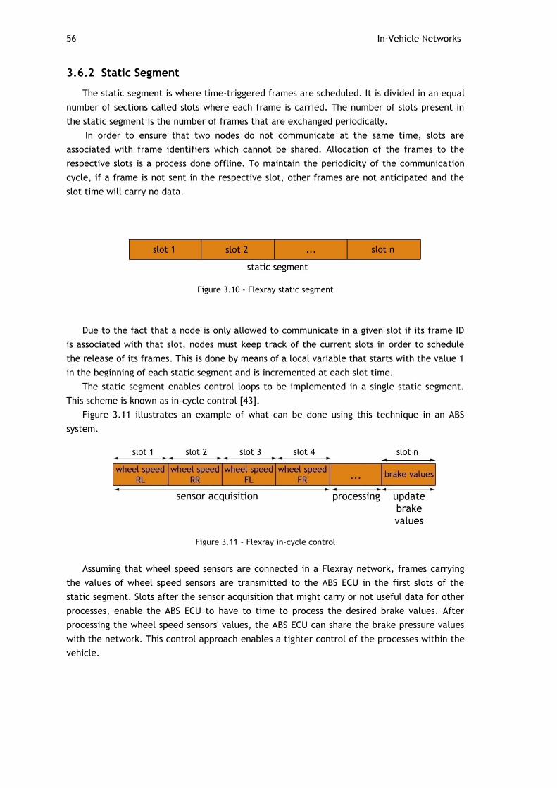
56 In-Vehicle Networks
3.6.2 Static Segment
The static segment is where time-triggered frames are scheduled. It is divided in an equal
number of sections called slots where each frame is carried. The number of slots present in
the static segment is the number of frames that are exchanged periodically.
In order to ensure that two nodes do not communicate at the same time, slots are
associated with frame identifiers which cannot be shared. Allocation of the frames to the
respective slots is a process done offline. To maintain the periodicity of the communication
cycle, if a frame is not sent in the respective slot, other frames are not anticipated and the
slot time will carry no data.
Figure 3.10 - Flexray static segment
Due to the fact that a node is only allowed to communicate in a given slot if its frame ID
is associated with that slot, nodes must keep track of the current slots in order to schedule
the release of its frames. This is done by means of a local variable that starts with the value 1
in the beginning of each static segment and is incremented at each slot time.
The static segment enables control loops to be implemented in a single static segment.
This scheme is known as in-cycle control [43].
Figure 3.11 illustrates an example of what can be done using this technique in an ABS
system.
Figure 3.11 - Flexray in-cycle control
Assuming that wheel speed sensors are connected in a Flexray network, frames carrying
the values of wheel speed sensors are transmitted to the ABS ECU in the first slots of the
static segment. Slots after the sensor acquisition that might carry or not useful data for other
processes, enable the ABS ECU to have to time to process the desired brake values. After
processing the wheel speed sensors' values, the ABS ECU can share the brake pressure values
with the network. This control approach enables a tighter control of the processes within the
vehicle.
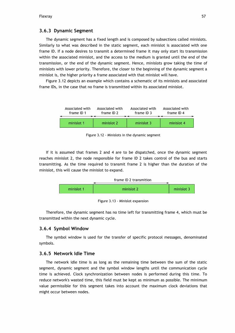
Flexray 57
3.6.3 Dynamic Segment
The dynamic segment has a fixed length and is composed by subsections called minislots.
Similarly to what was described in the static segment, each minislot is associated with one
frame ID. If a node desires to transmit a determined frame it may only start its transmission
within the associated minislot, and the access to the medium is granted until the end of the
transmission, or the end of the dynamic segment. Hence, minislots grow taking the time of
minislots with lower priority. Therefore, the closer to the beginning of the dynamic segment a
minislot is, the higher priority a frame associated with that minislot will have.
Figure 3.12 depicts an example which contains a schematic of its minislots and associated
frame IDs, in the case that no frame is transmitted within its associated minislot.
Figure 3.12 - Minislots in the dynamic segment
If it is assumed that frames 2 and 4 are to be dispatched, once the dynamic segment
reaches minislot 2, the node responsible for frame ID 2 takes control of the bus and starts
transmitting. As the time required to transmit frame 2 is higher than the duration of the
minislot, this will cause the minislot to expand.
Figure 3.13 - Minislot expansion
Therefore, the dynamic segment has no time left for transmitting frame 4, which must be
transmitted within the next dynamic cycle.
3.6.4 Symbol Window
The symbol window is used for the transfer of specific protocol messages, denominated
symbols.
3.6.5 Network Idle Time
The network idle time is as long as the remaining time between the sum of the static
segment, dynamic segment and the symbol window lengths until the communication cycle
time is achieved. Clock synchronization between nodes is performed during this time. To
reduce network's wasted time, this field must be kept as minimum as possible. The minimum
value permissible for this segment takes into account the maximum clock deviations that
might occur between nodes.

58 In-Vehicle Networks
3.6.6 Flexray Frame
The Flexray frame is composed by three main sections: the header, payload and trailer
segments. Figure 3.14 depicts the structure of a Flexray frame.
Figure 3.14 - Flexray frame [42]
3.6.6.1 Header Segment
The header segment is composed by the following bits/sections:
Reserved bit - reserved for future developments of the protocol.
Payload preamble indicator bit - in static frames this bit signals whether the
payload field contains a network management vector at its beginning. In case of
dynamic frames, it is used to indicate the presence of a message ID in the
beginning of the payload field. This bit is set to zero when none of the mentioned
data is present.
Null frame indicator bit - indicates whether the payload field contains data or
not. In case that the payload field is empty this bit is set to zero. In case that the
payload field contains useable data, it is set to one. The null frame indicator bit
serves as a way of providing the receiving nodes with information such as whether
the transmitting node had its data ready at the time of transmission of the frame
or not.
Sync frame indicator bit - is set to one if the frame is a synchronization frame
and is set to zero in the case that the frame is not a synchronization frame.
Start-up frame indicator bit - in case that the transmitted frame is a startup
frame, this bit is set to one. Startup frames are only sent by nodes during cold
start. The startup mechanism is not described in this document due to its
specificity. More information on the startup mechanism can be found in [42].
Flexray 59
Frame ID - identifies the content and sender of the frame. Each communication
slot has a frame ID associated to it. Hence, it is not allowed for nodes to share the
same frame IDs.
Payload length field - carries the number of words (sets of 16 bits) in the
payload field. Since the maximum number of bytes in the payload field is 254, this
section comprises 7 bits.
Header CRC - contains the CRC code calculated taking as basis the bits comprised
between the sync frame indicator until the end of the payload length field.
Cycle count - the cycle count field contains the number of the communication
cycle viewed from the transmitting node's perspective.
3.6.6.2 Payload Segment
The payload segment contains the data to be transferred in the frame. It can contain
from 0 to 254 bytes of data. Due to the fact that the payload length field specifies the
number of bytes to be carried as a mean of words, the payload segment always carries an
even number of bytes.
As it was mentioned in previous sections, the first bits of this section can either contain
the network management vector in case of frames transmitted in the static section or the
message ID, in the case of a dynamic frame. The inclusion of a message ID on the payload
field permits nodes to filter data based on the contents of this field.
3.6.6.3 Trailer Segment
The trailer segment contains a 24 bit CRC code for fault detection. A particular note on
the effectiveness of this code must be taken into account as the hamming distance offered by
this code depends on the length of the payload field. For payload fields which length is less or
equal to 248 bytes, the hamming distance offered by the CRC code is 6 whether in the case
that the payload length is higher than 248 bytes, the hamming distance offered is 4.
3.6.7 Error Processing, Management and Transmission Security
3.6.7.1 Bus guardian
The bus guardian is a device which monitors the communication channels. It is
independent from the communications controller and grants extra reliability to the system.
By knowing the frame schedule of the static section, it is able to detect if nodes erroneously
try to access the bus on instants where they are not allowed to. Upon detection of such
situations, the bus guardian can disable the bus drivers and notify the controller.
3.6.7.2 CRC codes
The CRC code mechanism is described on Section 3.5.5.3.
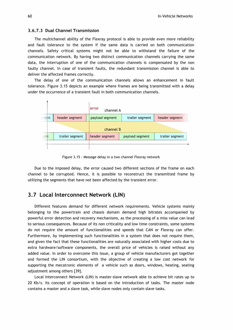
60 In-Vehicle Networks
3.6.7.3 Dual Channel Transmission
The multichannel ability of the Flexray protocol is able to provide even more reliability
and fault tolerance to the system if the same data is carried on both communication
channels. Safety critical systems might not be able to withstand the failure of the
communication network. By having two distinct communication channels carrying the same
data, the interruption of one of the communication channels is compensated by the non
faulty channel. In case of transient faults, the redundant transmission channel is able to
deliver the affected frames correctly.
The delay of one of the communication channels allows an enhancement in fault
tolerance. Figure 3.15 depicts an example where frames are being transmitted with a delay
under the occurrence of a transient fault in both communication channels.
Figure 3.15 - Message delay in a two channel Flexray network
Due to the imposed delay, the error caused two different sections of the frame on each
channel to be corrupted. Hence, it is possible to reconstruct the transmitted frame by
utilizing the segments that have not been affected by the transient error.
3.7 Local Interconnect Network (LIN)
Different features demand for different network requirements. Vehicle systems mainly
belonging to the powertrain and chassis domain demand high bitrates accompanied by
powerful error detection and recovery mechanisms, as the processing of a miss value can lead
to serious consequences. Because of its non criticality and low time constraints, some systems
do not require the amount of functionalities and speeds that CAN or Flexray can offer.
Furthermore, by implementing such functionalities in a system that does not require them,
and given the fact that these functionalities are naturally associated with higher costs due to
extra hardware/software components, the overall price of vehicles is raised without any
added value. In order to overcome this issue, a group of vehicle manufacturers got together
and formed the LIN consortium, with the objective of creating a low cost network for
supporting the mecatronic elements of a vehicle such as doors, windows, heating, seating
adjustment among others [39].
Local Interconnect Network (LIN) is master-slave network able to achieve bit rates up to
20 Kb/s. Its concept of operation is based on the introduction of tasks. The master node
contains a master and a slave task, while slave nodes only contain slave tasks.

Local Interconnect Network (LIN) 61
Many of the details presented in the LIN specification package are not discussed in this
section. More information is found in [44].
Figure 3.16 - LIN as a sub-bus of CAN [38]
3.7.1 LIN Frames
LIN frames are composed of two main sections: the header and the response field. The
two sections are separated by a response space. The header is transmitted by the master
task, while responses are provided by slave tasks.
Figure 3.17 - LIN frame [44]
LIN frames are composed of the following fields:
Break field - composed of at least 13 dominant bits and serves to signal all nodes
that a frame transfer is about to start. This field is delimited by one recessive bit
and is always transmitted by the master node.

62 In-Vehicle Networks
Synchronization field - enables nodes which use automatic baud rate detection
to perform synchronization with the master node. In this section the master
outputs the value 0x55 (1010101) so nodes can measure bit time through a
capture counter and adjust their baudrates accordingly.
Identifier - composed of 10 bits: 1 start bit, 6 identifier bits, 2 parity bits and 1
recessive delimiter bit. The identifier bits make it possible to address 64 possible
messages. However, addresses 60 and 61 are reserved for diagnostic data, address
62 for user defined extensions and 63 for future protocol enhancements. Parity
bits provide the header with a basic fault detection mechanism with 2 hamming
distance. The aggregation of the identifier and the parity bits is denominated the
protected identifier.
Data field - consists of up to a maximum 8 bits of data. It is outputted by slave
tasks in response to a given identifier.
Checksum - transmitted by the slave after the data field. It serves as the fault
detection mechanism for the data field. Upon arrival of the frame, the master
calculates the checksum in the same way and compares with the received value
to check for errors.
3.7.1.1 Types of LIN Frames
Despite that the structure of all frames is the same, the following types of frames are
listed in the LIN specification:
Unconditional
Event triggered
Sporadic
Diagnostic
User-defined
Reserved
The difference between frames types resides in the timing and content of the data.
Unconditional, event triggered and sporadic frames have particular bus access mechanisms
that are referred in Section 3.7.2.
3.7.2 BUS Access
The LIN protocol follows a master-slave approach. Slaves are not allowed to transmit
unless prompted. The determinism of the LIN protocol arises due to the fact that all of the
communication in the bus is controlled by the master. Following its schedule table, when the
master intends to cause a slave task to transmit a particular message, it outputs an header
whose ID is associated with that message.
By analyzing the header's identifier and upon a positive parity check, each slave task
determines whether if it is a publisher or subscriber of that particular ID. In case that the

Local Interconnect Network (LIN) 63
slave task is a publisher, it outputs a response. In the case that it is a subscribers, it listens to
the bus so the information can be processed.
Figure 3.18 - LIN bus access [44]
The master itself can send messages (responses) to other slaves. That is achieved by
placing a slave task in the master node. The slave task captures the header provided by the
master task and outputs its response.
3.7.2.1 Unconditional Frames Transfer
Unconditional frames are the data carrying frames. Figure 3.19 depicts an example of
three different situations upon the transfer of unconditional frames:
Figure 3.19 - Unconditional frames transfer [44]
1. Frames transfer between slave to master - the master outputs the header whose
identifier triggers the slave response. Upon reception of the header, slave 1 identifies
itself as the publisher of the data and replies with the appropriate data.
2. Frames transfer between master to slaves - the master outputs an header whose
identifier triggers the response from its own slave task
3. Frames transfer between slaves - the master outputs a header which will trigger
slave 1 to be the subscriber of the message and slave 2 to be the publisher. Upon
transmission of the frame by slave 2, slave 1 will capture and process the transmitted
data.
3.7.2.2 Event Triggered Frames Transfer
Figure 3.20 illustrates an example of an event triggered transfer. The purpose of event
triggered frames is to save bandwidth. This is achieved by associating multiple slave tasks to
the same ID. In case that an event has occurred in a particular slave, it sends its protected ID
(the ID which would be sent to query an unconditional frame) in the first data byte, so the
master task can identify the node where the event has occurred.
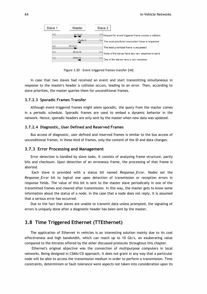
64 In-Vehicle Networks
Figure 3.20 - Event triggered frames transfer [44]
In case that two slaves had received an event and start transmitting simultaneous in
response to the master's header a collision occurs, leading to an error. Then, according to
slave priorities, the master queries them for unconditional frames.
3.7.2.3 Sporadic Frames Transfer
Although event-triggered frames might seem sporadic, the query from the master comes
in a periodic schedule. Sporadic frames are used to embed a dynamic behavior in the
network. Hence, sporadic headers are only sent by the master when new data was updated.
3.7.2.4 Diagnostic, User Defined and Reserved Frames
Bus access of diagnostic, user defined and reserved frames is similar to the bus access of
unconditional frames. In these kind of frames, only the content of the ID and data changes.
3.7.3 Error Processing and Management
Error detection is handled by slave tasks. It consists of analyzing frame structure, parity
bits and checksum. Upon detection of an erroneous frame, the processing of that frame is
aborted.
Each slave is provided with a status bit named Response_Error. Nodes set the
Response_Error bit to logical one upon detection of transmission or reception errors in
response fields. The value of this bit is sent to the master slave periodically in one of the
transmitted frames and cleared after transmission. In this way, the master gets to know some
information about the status of a node. In the case that a node does not reply, it is assumed
that a serious error has occurred.
Due to the fact that slaves are unable to transmit data unless prompted, the signaling of
errors is uniquely done after a diagnostic header has been sent by the master.
3.8 Time Triggered Ethernet (TTEthernet)
The application of Ethernet in vehicles is an interesting solution mainly due to its cost
effectiveness and high bandwidth, which can reach up to 10 Gb/s, an exuberating value
compared to the bitrates offered by the other discussed protocols throughout this chapter.
Ethernet's original objective was the connection of multipurpose computers in local
networks. Being designed in CSMA/CD approach, it does not grant in any way that a particular
node will be able to access the transmission medium in order to perform a transmission. Time
constraints, determinism or fault tolerance were aspects not taken into consideration upon its

Time Triggered Ethernet (TTEthernet) 65
design. Therefore, in its original form, Ethernet is not able to fulfill the requirements that
support its integration in vehicle control systems.
TTEthernet expands the classical Ethernet to meet these requirements [45]. It achieves
this by generating services on top of unchanged Ethernet. The concept behind TTEthernet is
the transformation of messages from higher layer protocols into time-triggered messages
without changing its content. Therefore, it can be said that TTEthernet concerns only the
instants when these messages are sent.
TTEthernet permits that messages with different levels of determinism can coexist in the
same network. It is possible for strict control data to be placed in the same network with
media data, which does not require strict determinism but instead a defined maximum
latency, or even webservices in a best effort scheme, where determinism is not required at
all. Furthermore, it may achieve this while granting high levels of reliability and fault
tolerance.
3.8.1 Operational Principles and Architectures
TTEthernet's basic architecture assumes the star form, in which a router is the central
element. Multiple stars can be cascaded, even with segments with different bandwidths.
Redundancy, which is discussed in Section 3.8.3 can also be implemented in order to achieve
extra reliability and fault tolerance.
Figure 3.21 - TTEthernet redundant architecture [45]
Switches act as the core of the protocol, being responsible for the organization of
incoming frames and posterior transmission in the appropriate instants, according to the
predefined schedule.
The transmission of time-triggered (TT) messages requires a common sense of time
between the interacting nodes. This implies that all nodes involved in the transmission and
reception of time triggered frames must be synchronized. The synchronization process is
quite extensible for the matters of this work and a detailed explanation of it can be found in
[46].

66 In-Vehicle Networks
Upon reception of scheduled time-triggered messages, switches immediately route frames
to the respective network segment. Due to the fact that the transmission of these messages is
scheduled offline, in error free operation the output transmission segment is always free.
Rate constrained (RC) messages are routed immediately if no TT messages are awaiting to
be transmitted, and best effort (BE) messages take the remaining bandwidth. Switches have
buffers for each kind of messages. In the case of high network load, the switch can notify the
sending nodes that its buffer is full.
3.8.2 Types of Messages
There are three different kinds of messages that may be exchanged in TTEthernet which
are presented as follows.
3.8.2.1 Time Triggered Messages (TT messages)
TT messages are messages sent by nodes at predefined instants. These messages have the
maximum priority over the other types of messages, and used for exchanging strict
deterministic control data.
3.8.2.2 Rate Constrained Messages (RC messages)
Not all control data requires strict determinism. A limited delay and temporal deviation
can be enough to fulfill some applications' requirements. RC messages are used to carry these
messages, which can vary from automotive applications with moderate timing requirements
to multimedia data. The transfer of RC messages is not synchronized taking as basis a
common schedule. Hence it is possible that different nodes transmit these messages at the
same point in time, which may lead to queues on the switching devices, which will result in
jitter.
3.8.2.3 Best Effort Messages (BE messages)
Best effort messages are the classical Ethernet messages. These messages do not rely in
any of the services provided by TTEthernet and have the lowest value of priority comparing to
the other kind of messages described. There is not an upper boundary on the time that will
take for a message of this kind to get to the destination, or even it will actually get there.
Best effort messages are transmitted in free network times between transmission of TT and
RC messages, thus optimizing the use of bandwidth.
3.8.3 Reliability and Fault Tolerance
Being the central element in the network topology, switches have the ability to behave
like bus guardians. Due to the fact that these are directly connected to nodes, errors can be
detected and appropriate measures can be taken, such as disabling of communication drivers
of the erroneous node or the masking of the error, depending on whether redundancy is
present or not.
The network structure can be designed to accommodate the desired level of reliability
and fault tolerance. This can be achieved by adding redundancy to the switch and to the
communication channels in each node. Figure 3.22 depicts an example of a network structure
offering three redundancy channels.
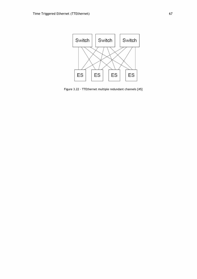
Time Triggered Ethernet (TTEthernet) 67
Figure 3.22 - TTEthernet multiple redundant channels [45]

68 In-Vehicle Networks
69
Chapter 4
Drive-by-wire systems and guidelines for fault tolerant hardware design
4.1 Motivation for this Chapter
At the present moment, no vehicle available in the market employs a full by-wire scheme.
Given the importance that this subject will have on the next generation of vehicles, some of
the concepts behind this philosophy are presented in this chapter. The development of safety
critical systems is complex and requires a profound study on the matter. However, it is
possible for students to build simple dependable systems by exploring the concepts and ideas
presented in this section.
4.2 Introduction to Drive-by-wire Systems
The first vehicles in the market were entirely dependent on the use of mechanical and
hydraulic components. The introduction of electronic components in these systems, allowed
major improvements in the automotive industry in terms of safety, economy and comfort.
X-by-wire is the designation of a field of studies that has the ultimate goal of replacing all
mechanical transmission linkages by communication networks and mechanical actuators by
electrical actuators [47]. The reduction of mechanical components in vehicles allows for new
vehicle designs due to an increase of available space, lower maintenance, decrease assembly
time and improve safety, as mechanical components like for instance the steering column are
a potential deadly element to the driver in case of impact [48].
X-by-wire systems are gradually being introduced in a two stage process. The first stage is
the introduction of x-by-wire systems in which mechanical backup systems are automatically
activated in the event of erroneous operation. The control units that operate such systems
must possess self checking mechanisms that are able to detect errors. Such units are named
fail-silent units (FSU). The second stage of the implementation of x-by-wire systems is their
integration without mechanical backup. By having no mechanical backup, these systems must
be fault tolerant. As it will be seen, fault tolerance is achieved by means of component
redundancy. Multiple FSUs working together form a fault-tolerant unit (FTU).

70 Drive-by-wire systems and guidelines for fault tolerant hardware design
Figure 4.1 - Citroen C5 by wire: acceleration and braking integrated in the steering wheel [48]
Figure 4.2 - General Motors Hy-wire concept car [49]
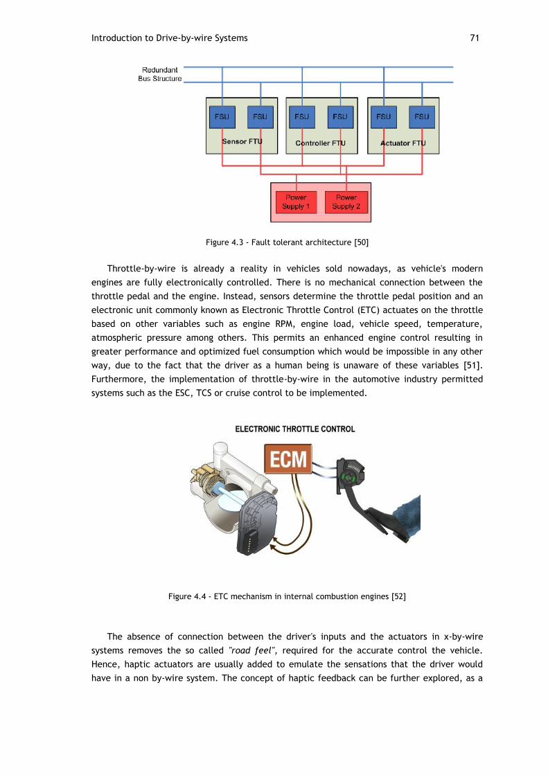
Introduction to Drive-by-wire Systems 71
Figure 4.3 - Fault tolerant architecture [50]
Throttle-by-wire is already a reality in vehicles sold nowadays, as vehicle's modern
engines are fully electronically controlled. There is no mechanical connection between the
throttle pedal and the engine. Instead, sensors determine the throttle pedal position and an
electronic unit commonly known as Electronic Throttle Control (ETC) actuates on the throttle
based on other variables such as engine RPM, engine load, vehicle speed, temperature,
atmospheric pressure among others. This permits an enhanced engine control resulting in
greater performance and optimized fuel consumption which would be impossible in any other
way, due to the fact that the driver as a human being is unaware of these variables [51].
Furthermore, the implementation of throttle-by-wire in the automotive industry permitted
systems such as the ESC, TCS or cruise control to be implemented.
Figure 4.4 - ETC mechanism in internal combustion engines [52]
The absence of connection between the driver's inputs and the actuators in x-by-wire
systems removes the so called "road feel", required for the accurate control the vehicle.
Hence, haptic actuators are usually added to emulate the sensations that the driver would
have in a non by-wire system. The concept of haptic feedback can be further explored, as a
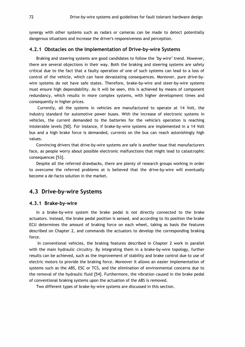
72 Drive-by-wire systems and guidelines for fault tolerant hardware design
synergy with other systems such as radars or cameras can be made to detect potentially
dangerous situations and increase the driver's responsiveness and perception.
4.2.1 Obstacles on the Implementation of Drive-by-wire Systems
Braking and steering systems are good candidates to follow the "by-wire" trend. However,
there are several objections in their way. Both the braking and steering systems are safety
critical due to the fact that a faulty operation of one of such systems can lead to a loss of
control of the vehicle, which can have devastating consequences. Moreover, pure drive-by-
wire systems do not have safe states. Therefore, brake-by-wire and steer-by-wire systems
must ensure high dependability. As it will be seen, this is achieved by means of component
redundancy, which results in more complex systems, with higher development times and
consequently in higher prices.
Currently, all the systems in vehicles are manufactured to operate at 14 Volt, the
industry standard for automotive power buses. With the increase of electronic systems in
vehicles, the current demanded to the batteries for the vehicle's operation is reaching
intolerable levels [50]. For instance, if brake-by-wire systems are implemented in a 14 Volt
bus and a high brake force is demanded, currents on the bus can reach astonishingly high
values.
Convincing drivers that drive-by-wire systems are safe is another issue that manufacturers
face, as people worry about possible electronic malfunctions that might lead to catastrophic
consequences [53].
Despite all the referred drawbacks, there are plenty of research groups working in order
to overcome the referred problems at is believed that the drive-by-wire will eventually
become a de-facto solution in the market.
4.3 Drive-by-wire Systems
4.3.1 Brake-by-wire
In a brake-by-wire system the brake pedal is not directly connected to the brake
actuators. Instead, the brake pedal position is sensed, and according to its position the brake
ECU determines the amount of braking force on each wheel, taking as basis the features
described on Chapter 2, and commands the actuators to develop the corresponding braking
force.
In conventional vehicles, the braking features described in Chapter 2 work in parallel
with the main hydraulic circuitry. By integrating them in a brake-by-wire topology, further
results can be achieved, such as the improvement of stability and brake control due to use of
electric motors to provide the braking force. Moreover it allows an easier implementation of
systems such as the ABS, ESC or TCS, and the elimination of environmental concerns due to
the removal of the hydraulic fluid [54]. Furthermore, the vibration caused in the brake pedal
of conventional braking systems upon the actuation of the ABS is removed.
Two different types of brake-by-wire systems are discussed in this section.

Drive-by-wire Systems 73
4.3.1.1 Electro Hydraulic Brakes (EHB)
Electro hydraulic brakes are the first evolution of conventional brakes to brake-by-wire
systems. These systems cannot be called pure by-wire systems, due to the fact that a backup
hydraulic connection between the brake pedal and the hydraulic modulator exists, and is
enabled in the case of erroneous operation of the brake ECU.
The brake force is generated by hydraulic means, but lacks the direct connection
between the brake pedal and the hydraulic modulator under normal operation. Signals from
the brake pedal sensors travel to the brake ECU, which determines the appropriate brake
value on each wheel taking as basis the braking features described in Chapter 2. The
determined braking values for each wheel are transferred to the hydraulic control unit (HCU),
which actuates the hydraulic circuits to generate the desired braking force [50].
Figure 4.5 - Electro hydraulic brakes scheme [50]
4.3.1.2 Electro Mechanical Brakes (EMB)
Electro mechanical brakes reflect the pure concept of x-by-wire systems due to the fact
that a mechanical connection between the brake pedal and the brake actuators is absent.
The EMB operation is similar to the EHB but, instead of transmitting the brake signals to the
HCU, the brake ECU transmits braking forces by wire to individual wheel brake modules
placed on each wheel, which have the task of providing the determined brake force by means
of electro-mechanical actuators. A scheme of electro mechanical brakes can be found in
Figure 4.6:
Figure 4.6 - Electro mechanical brake-by-wire [50]

74 Drive-by-wire systems and guidelines for fault tolerant hardware design
Figure 4.7 - Continental electro mechanical brake [55]
4.3.2 Steer-by-wire
Steer-by-wire expands the by-wire concept to the vehicle's steering system. Hence, no
mechanical connection between the steering wheel and the tires exist.
Sensors placed in the steering wheel transmit its position and torque to an ECU which in
turn actuates electric motors in the front axle to steer the wheels. A unit called hand wheel
actuator is responsible for providing the haptic feedback to the driver [56].
4.4 Fault Tolerant Hardware Architectures Design
Many of the systems described along this document are safety critical. Being safety
critical means that the failure or malfunction of such systems can lead to potential
catastrophic situations such as the death of people, significant damage or loss of equipment,
and environmental harm [57]. Hence, it must be assured that these systems grant appropriate
levels of dependability, the level of confidence in which the system can be expected to
perform its functions.
The brief discussion of the development of safety critical systems that follows takes as
basis the standard IEC 61508 which addresses multipurpose safety related systems. ISO 26262
is a standard that is currently being developed uniquely for the automotive industry based on
IEC 61508. Given the fact that ISO 26262 standard is not yet available [58], the classifications
that follow are based on IEC 61508.
The development of safety critical systems starts by the analysis of the ways in which the
target system can be the source of hazards. Hazards can be defined as situations that have
the potential to cause harm to people or the environment. There are several methodologies
that aid the identification of the events that lead to hazards and their consequences such as
the FMEA (failure modes and events analysis), ETA (event tree analysis), FTA (fault tree
analysis) among others [57]. Once the sequences of events that lead to hazards are
determined, the frequency of occurrence of each hazard can be calculated.
The frequency of each hazard combined with its consequences make up what is called
risk. IEC 61508 provides the classification for both the consequences, frequency and
associated risk of hazards.

Fault Tolerant Hardware Architectures Design 75
Table 4.1 - Risk classification according to IEC 61508
Consequences
Frequency Catastrophic Critical Marginal Negligible
Frequent I I I II
Probable I I II III
Occasional I II III III
Remote II III III IV
Improbable III III IV IV
Incredible IV IV IV IV
Table 4.2 - Interpretation of the various risk levels according to IEC 61508
Risk class Interpretation
I Intolerable risk
II Undesirable risk, and tolerable only if risk reduction is impracticable or if
the costs are grossly disproportionate to the improvement gained
III Tolerable risk if the cost of risk reduction would exceed the improvement
gained
IV Negligible risk
Risk classification serves as basis for the determination of a safety integrity level. Safety
integrity levels reflect the level of dependability of safety systems and condition not only the
system's architecture but its development process.
IEC 61508 provides target failure rates for the four proposed integrity levels according to
different modes of operation: a continuous mode and a low demand mode. As an example,
the braking system would be considered for the continuous mode operation SIL levels, while
the airbag system would be considered for the demand mode of operation. The classification
on the continuous mode of operation takes as basis the number of failures per hour, while the
on demand mode of operation takes as basis the probability of the system not to respond
appropriately to the request.
Table 4.3 - IEC 61508 safety integrity levels for continuous mode of operation
Safety Integrity Level Failures per hour
4 10−8 to 10−9
3 10−7 to 10−8
2 10−7 to 10−6
1 10−5 to 10−6
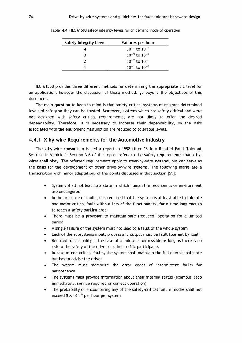
76 Drive-by-wire systems and guidelines for fault tolerant hardware design
Table 4.4 - IEC 61508 safety integrity levels for on demand mode of operation
Safety Integrity Level Failures per hour
4 10−4 to 10−5
3 10−3 to 10−4
2 10−2 to 10−3
1 10−1 to 10−2
IEC 61508 provides three different methods for determining the appropriate SIL level for
an application, however the discussion of these methods go beyond the objectives of this
document.
The main question to keep in mind is that safety critical systems must grant determined
levels of safety so they can be trusted. Moreover, systems which are safety critical and were
not designed with safety critical requirements, are not likely to offer the desired
dependability. Therefore, it is necessary to increase their dependability, so the risks
associated with the equipment malfunction are reduced to tolerable levels.
4.4.1 X-by-wire Requirements for the Automotive Industry
The x-by-wire consortium issued a report in 1998 titled "Safety Related Fault Tolerant
Systems in Vehicles". Section 3.6 of the report refers to the safety requirements that x-by-
wires shall obey. The referred requirements apply to steer-by-wire systems, but can serve as
the basis for the development of other drive-by-wire systems. The following marks are a
transcription with minor adaptations of the points discussed in that section [59]:
Systems shall not lead to a state in which human life, economics or environment
are endangered
In the presence of faults, it is required that the system is at least able to tolerate
one major critical fault without loss of the functionality, for a time long enough
to reach a safety parking area
There must be a provision to maintain safe (reduced) operation for a limited
period
A single failure of the system must not lead to a fault of the whole system
Each of the subsystems input, process and output must be fault tolerant by itself
Reduced functionality in the case of a failure is permissible as long as there is no
risk to the safety of the driver or other traffic participants
In case of non critical faults, the system shall maintain the full operational state
but has to advise the driver
The system must memorize the error codes of intermittent faults for
maintenance
The systems must provide information about their internal status (example: stop
immediately, service required or correct operation)
The probability of encountering any of the safety-critical failure modes shall not
exceed 5 × 10⁻¹⁰ per hour per system

Fault Tolerant Hardware Architectures Design 77
By the analysis of these requirements it can be concluded that automotive drive-by-wire
systems must be highly dependable. In fact the integrity level required for x-by-wire systems
is even higher than SIL 4, the highest integrity level referred on IEC 61508.
4.4.2 Increasing Dependability
The two most common ways of increasing a systems' dependability are: fault avoidance
and fault tolerance [60].
4.4.2.1 Fault Avoidance
Fault avoidance is based on the concept of ensuring quality in all aspects: system design,
components and their protection such as electromagnetic interference (EMI) shielding and
system maintenance. The amount of extra dependability provided by fault avoidance methods
is somewhat limited to the demands of safety critical systems [60].
4.4.2.2 Fault Tolerance
Given the fact that any element despite of its quality will eventually fail, fault tolerance
mechanisms must be employed to ensure that no fault can result in system failure, as
required by drive-by-wire design requirements. Fault tolerance is achieved by means of
redundancy. The objective of redundancy is that the overall system to achieve higher
reliability than the parts that compose it, and the elimination of single points of failure [60].
There are three different kinds of hardware redundancy: static, dynamic, and hybrid
redundancy [57]. Static and dynamic redundancy are usually applied in drive-by-wire systems
and therefore are discussed in this section.
The discussion on hybrid redundancy is left behind as it is mostly used in the aircraft
industry. Hybrid redundancy reflects the combination between static and dynamic
redundancy. Despite achieving the best results in terms of reliability, it usually requires a
large amount of components and high complexity.
The following examples of architectures reflect simplifications of the questions involved.
A more detailed approach on a solution for a brake-by-wire system is given in Chapter 5.
Static Redundancy
Static redundancy uses fault masking as its basic principle. It consists on having several
elements performing the same functions in parallel and a voting mechanism which is
responsible for outputting a single value out of the values provided by the units in parallel.
Static redundant systems do not perform reconfiguration upon faults. The voting
mechanism can either be another device or the process itself.
N-modular Redundancy (NMR) Architectures
N-modular redundancy reflects the general concept of static redundancy. These
architectures are constituted by N odd elements in parallel. In order for the voter to find an
agreement, this system has to be built with at least three working units. This system is able
to tolerate failures within 𝑁−1
2 different modules.
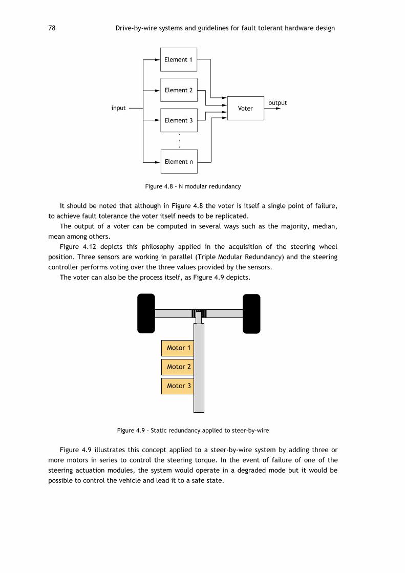
78 Drive-by-wire systems and guidelines for fault tolerant hardware design
Figure 4.8 - N modular redundancy
It should be noted that although in Figure 4.8 the voter is itself a single point of failure,
to achieve fault tolerance the voter itself needs to be replicated.
The output of a voter can be computed in several ways such as the majority, median,
mean among others.
Figure 4.12 depicts this philosophy applied in the acquisition of the steering wheel
position. Three sensors are working in parallel (Triple Modular Redundancy) and the steering
controller performs voting over the three values provided by the sensors.
The voter can also be the process itself, as Figure 4.9 depicts.
Figure 4.9 - Static redundancy applied to steer-by-wire
Figure 4.9 illustrates this concept applied to a steer-by-wire system by adding three or
more motors in series to control the steering torque. In the event of failure of one of the
steering actuation modules, the system would operate in a degraded mode but it would be
possible to control the vehicle and lead it to a safe state.
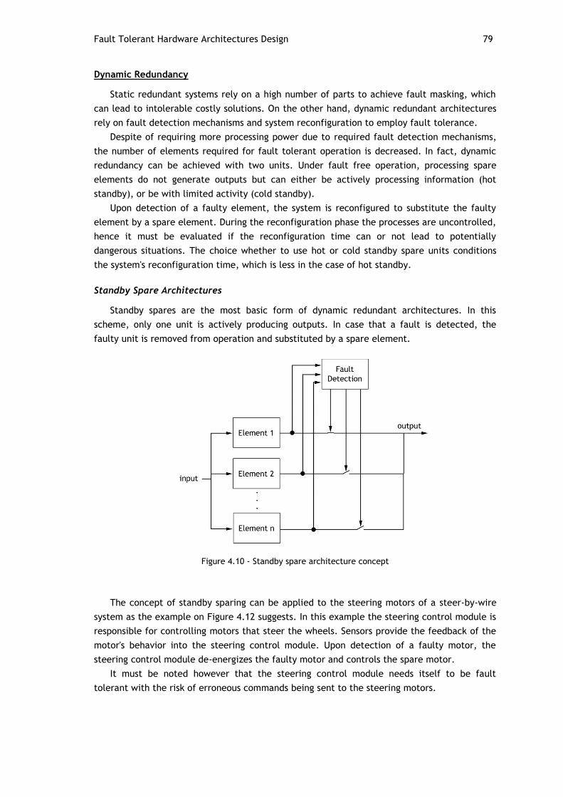
Fault Tolerant Hardware Architectures Design 79
Dynamic Redundancy
Static redundant systems rely on a high number of parts to achieve fault masking, which
can lead to intolerable costly solutions. On the other hand, dynamic redundant architectures
rely on fault detection mechanisms and system reconfiguration to employ fault tolerance.
Despite of requiring more processing power due to required fault detection mechanisms,
the number of elements required for fault tolerant operation is decreased. In fact, dynamic
redundancy can be achieved with two units. Under fault free operation, processing spare
elements do not generate outputs but can either be actively processing information (hot
standby), or be with limited activity (cold standby).
Upon detection of a faulty element, the system is reconfigured to substitute the faulty
element by a spare element. During the reconfiguration phase the processes are uncontrolled,
hence it must be evaluated if the reconfiguration time can or not lead to potentially
dangerous situations. The choice whether to use hot or cold standby spare units conditions
the system's reconfiguration time, which is less in the case of hot standby.
Standby Spare Architectures
Standby spares are the most basic form of dynamic redundant architectures. In this
scheme, only one unit is actively producing outputs. In case that a fault is detected, the
faulty unit is removed from operation and substituted by a spare element.
Figure 4.10 - Standby spare architecture concept
The concept of standby sparing can be applied to the steering motors of a steer-by-wire
system as the example on Figure 4.12 suggests. In this example the steering control module is
responsible for controlling motors that steer the wheels. Sensors provide the feedback of the
motor's behavior into the steering control module. Upon detection of a faulty motor, the
steering control module de-energizes the faulty motor and controls the spare motor.
It must be noted however that the steering control module needs itself to be fault
tolerant with the risk of erroneous commands being sent to the steering motors.
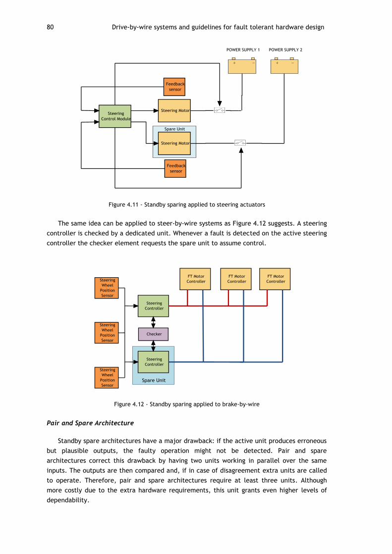
80 Drive-by-wire systems and guidelines for fault tolerant hardware design
Figure 4.11 - Standby sparing applied to steering actuators
The same idea can be applied to steer-by-wire systems as Figure 4.12 suggests. A steering
controller is checked by a dedicated unit. Whenever a fault is detected on the active steering
controller the checker element requests the spare unit to assume control.
Figure 4.12 - Standby sparing applied to brake-by-wire
Pair and Spare Architecture
Standby spare architectures have a major drawback: if the active unit produces erroneous
but plausible outputs, the faulty operation might not be detected. Pair and spare
architectures correct this drawback by having two units working in parallel over the same
inputs. The outputs are then compared and, if in case of disagreement extra units are called
to operate. Therefore, pair and spare architectures require at least three units. Although
more costly due to the extra hardware requirements, this unit grants even higher levels of
dependability.
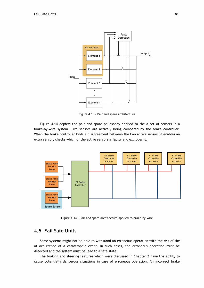
Fail Safe Units 81
Figure 4.13 - Pair and spare architecture
Figure 4.14 depicts the pair and spare philosophy applied to the a set of sensors in a
brake-by-wire system. Two sensors are actively being compared by the brake controller.
When the brake controller finds a disagreement between the two active sensors it enables an
extra sensor, checks which of the active sensors is faulty and excludes it.
Figure 4.14 - Pair and spare architecture applied to brake-by-wire
4.5 Fail Safe Units
Some systems might not be able to withstand an erroneous operation with the risk of the
of occurrence of a catastrophic event. In such cases, the erroneous operation must be
detected and the system must be lead to a safe state.
The braking and steering features which were discussed in Chapter 2 have the ability to
cause potentially dangerous situations in case of erroneous operation. An incorrect brake

82 Drive-by-wire systems and guidelines for fault tolerant hardware design
operation by the ABS, TCS or ESC has the potential of affecting the stability of the vehicle.
Similarly, erroneous steering assistance provided by power steering systems have the
potential to cause the driver to lose control of the vehicle. Therefore, it must be granted that
these systems fail in a safe way. Failing in a safe way in systems which have mechanical
backup is achieved by making computational units to stop producing outputs. Units that
behave in this way are denominate fail safe units.
Two main hardware strategies that rely on multiple cores can be applied to detect
failures and lead the system to a safe state: a master/checker approach and a comparative
duplication mechanism.
4.5.1 Master/checker Approach
The master/checker approach consists on having a main microcontroller be periodically
checked by another microcontroller, typically with less computational power for the sake of
cost saving. Upon detection of erroneous behavior by the checking unit, measures are taken
to prevent the master from producing outputs.
4.5.2 Duplication with Comparison
Duplication with comparison consists on having two microcontrollers performing the same
operations and comparing the outputs. The two microcontrollers can run the same software
or employ different software versions, in which case software faults can also be detected.
In any case, if the outputs from both microcontrollers do not match, the system is lead to
a safe state.
4.6 Hardware for Safety Critical Systems
As more dependability is being demanded to computational units, manufacturers are now
offering on-chip solutions to meet the requirements of safety standards [61].
Some of the most popular features are presented in this section.
4.6.1 Integrated Voltage Regulators
Improper voltage fed to the microcontroller can lead to unexpected behavior and
consequently, to faulty operation. Integrated voltage regulators have the task of feeding a
constant voltage to the microcontroller components regardless of the voltage fluctuations in
the source.
4.6.2 Voltage Monitors
Voltage monitors supervise the voltage fed to the microcontroller and engage safety
measures in case of high or low voltage detected.
4.6.3 Memory Protection Unit (MPU)
The memory protection unit is a hardware feature that splits the physical memory into
several slots, and assigns different rights to each of the memory accessing entities (CPU,
communication interfaces etc..), preventing overlapping, unauthorized access and protecting
memory sections.

Hardware for Safety Critical Systems 83
4.6.4 Error Correction Code Protected memories (ECC)
In ECC memories data is stored with additional redundancy so its accuracy can be tested
when saving or retrieving data from the memory. Several mechanisms can be employed in
protected memories such as parity bits, duplication codes, checksums, cyclic redundancy
check codes among others. Some of the coding mechanisms allow corrupt data to be
recovered, at the cost of higher overhead.
4.6.5 Clock Monitoring Units
Clock monitoring units check for deviations on the generated clock frequency. In the case
that the clock frequency deviates from a determined threshold, safety measures are engaged.
4.6.6 Peripheral Components Replication
Component replication enables the outputs from components such as analog to digital
converters, counters among others to be compared. In case of non matching outputs between
two redundant units, microcontrollers or special safety related units are signaled so safety
measures can be carried.
4.6.7 Watchdog Timers
Watchdog timers are special safety related timers with the goal of ensuring that the
supervised unit is actively performing its operations. The supervised unit periodically resets
the watchdog timer value. In the case that the watchdog reaches its maximum value, which
may happen in case of erroneous operation in the supervised unit, safety measures such as
resetting the microcontroller are carried. Watchdog timers are able to detect not only
hardware lack of response or overload failures but also software faults, in which programs
may fail to reset the watchdog timer due to erroneous operation.
4.6.8 Dual Core Microcontrollers for Safety Applications
In safety dual core microcontrollers the processors and other critical components are
replicated in order to attain higher integrity levels. Figure 4.15 depicts the block diagram of
the Freescale MPC564xL microcontrollers family, designed specifically for the needs of
automotive safety related systems.
The replicated elements are bounded by redundancy checking units, whose aim is to
supervise the consistency between the two sets of replicated units. Every time a
disagreement between the outputs of the replicated modules is observed, the redundancy
checker signals the fault collection and control unit (FCCU), which in turn enables safety
measures depending on the nature of the detected fault.
The processors from dual core microcontrollers can be configured to operate into two
distinct modes: the lock step mode (LSM) and the decoupled parallel mode (DPM).
4.6.8.1 Lock Step Mode (LSM)
In lock step mode the two processors operate synchronously. The same instructions are
executed at the same by each of the processors. The outputs of both processors are compared
by hardware and in case of deviation the system is lead to a safe state.
In this way, failures affecting one of the processors are widely detected and signaled in
short amounts of time, without any software intervention.

84 Drive-by-wire systems and guidelines for fault tolerant hardware design
4.6.8.2 Decoupled Parallel Mode (DPM)
In the decoupled parallel mode, processors work independently. Hence, no hardware fault
detection is possible without the implementation of specific fault detection software.
Software fault detection mechanisms using the DPM are described in [62].
Figure 4.15 - MPC5643L block diagram [63]

85
Chapter 5
Architecture Definition
In this Chapter, the concepts and ideas explored in previous chapters are put together to
form a conceptual architecture for the backbone architecture of the vehicle. Afterwards, a
proposed architecture for the braking system is explored in detail, along with the algorithms
which support the correct behavior of its hardware elements.
The objective of the development of the FEUP's EV is not the creation of a vehicle to be
driven on the public road. Instead, the main goal of this project is the development of a
vehicle that can be designed and assembled by students taking in consideration the price of
components and availability, the students learning curve and the knowledge obtained in the
various courses along their academic career. Therefore, the proposed architecture does not
include most of the de-facto solutions present in most of the commercially available vehicles.
Most of the systems described in this document are too complex to be developed by a
single working group in a reasonable amount of time. In order for this project to be feasible
by students, the proposed architecture is based on the idea of isolating the boundary of each
feature up to the maximum degree possible. This means that functionalities that would
normally share a single ECU (like for instance most of the discussed braking functionalities)
must be divided to form a network of less complex control units. In this way, students will not
be restrained on the use of a particular hardware/software platform and are free to make
their own decisions.
However, given the fact that multiple dependencies between functionalities and systems
exist, it is not possible nor practical for all functionalities/systems to be completely
independent. Several functionalities, such as the TCS which relies both on the brake and
motor ECUs operate in a distributed fashion. Therefore, in order for the implementation of
distributed algorithms to be possible, the software specification on each module must include
a set of services that allow the interaction between ECUs. Global awareness of variables that
might interest several ECUs should also be provided. These issues should be solved by means
of appropriate software and middleware specification.
Although the main focus of this work is hardware, brief references to software have to be
made to aid the explanation of concepts behind the proposed architectures.

86 Architecture Definition
5.1 High Level Architecture
The following set of requirements were considered for the definition of the proposed
architecture:
1. Networks interconnecting vehicle systems must be within those which are
lectured in the students curricular plan, or be congruent with the students
learning curve
2. It shall be possible for students to easily integrate their systems with any other
systems present in the vehicle
3. The architecture must be scalable
4. Network components shall be inexpensive
From these requirements, CAN and Ethernet were considered to be viable options to serve
as the communication backbone for the EV. However, as it is discussed in Chapter 3, CAN's 1
Mb/s bandwidth might impose limitations on the system's scalability. Hence, to give room for
the maximum number of systems to be integrated Ethernet shall be used as the
communication backbone for the EV.
Figure 5.1 depicts the high level view of the proposed architecture. This architecture
consists on having the main systems discussed in Chapter 2 connected to each other on a star
topology by means of an Ethernet switch.
Figure 5.1 - High level view of the proposed architecture
It must be noted however, that if the bandwidth required for the various systems to
exchange data is less than 1 Mbps, CAN is considered to be a viable solution to serve as the
backbone for the EV. Instead of a star topology, all the systems would be simply integrated in
a bus topology. This solution allows for real-time behavior of distributed control algorithms,
at the cost of requiring a study on the schedulability and CAN priority assignment of all
frames that are expected to be exchanged.

High Level Architecture 87
5.1.1 Architecture Limitations
Ethernet was not tailored to support the exchange of data in real time. Hence, it cannot
provide the desired level of determinism required for the operation of systems which rely on
data exchanges between multiple ECUs.
The fact that that the switch is a central element connecting all ECUs implies that its
failure will lead to the failure of all the features which rely on data exchanges between
multiple ECUs. Hence, the failure of the switch will eventually lead to the failure of systems
such as the ACC, power steering, TCS, ESC, instrument panel among others. In order for this
issue to be minimized, such systems must be provided with software mechanisms which
detect the failure of the Ethernet switch and engage safety measures such as vehicle speed
limitation, so the driver can lead it to a safe state.
5.1.2 Data Exchange between ECUs
Certain functionalities require the knowledge of variables that might not be produced
within the ECU where the feature is implemented. Vehicle's speed for instance, is a variable
that can be either produced on the motor or brake ECUs and is required by functionalities
that operate in other ECUs such as steering, lights and instrument panel ECUs.
A possible solution for this issue that would also allow the integration of additional
systems with minimum effort, would be the transmission of several variables of interest in a
publisher/subscriber pattern. This would allow for a scalable solution which permits the
integration of additional systems that require those variables in a plug-and-play fashion.
A deep study regarding the functionalities to be implemented must be carried in order to
determine all the variables of interest to be published. The following tables depict several
examples:
Table 5.1 - Motor variables of interest
Variable Potential Subscriber(s) Function
Vehicle Speed Instrument Panel ECU Vehicle speed display
Brake ECU Wheel slip detection
Steering ECU Steering assist force adjustment
Lights ECU Adaptive Cornering light function
RPM Instrument Panel ECU RPM display
Motor Torque Brake ECU Electronic Stability Program, Traction
Control System
Motor
Temperature
Instrument Panel ECU Motor Temperature Display
Table 5.2- Lights ECU variables of interest
Variable Potential Subscriber(s) Function
Lights status Instrument Panel Light Status display

88 Architecture Definition
Table 5.3 - Brake ECU variables of interest
Variable Potential Subscriber(s) Function
ABS, TCS, ESC, EBD and
BA activity
Instrument Panel ECU Activity display
Adaptive Cruise Control Adaptive cruise control disable
Cruise Control Cruise Control disable
Brake activity Adaptive Cruise Control Adaptive cruise control disable
Cruise Control Cruise Control disable
Brake Diagnostics Instrument Panel ECU Diagnostic Message Display
Motor ECU Speed limitation upon bad diagnostic
Yaw Momentum Lights ECU Adaptive Cornering Light Function
Lateral Acceleration Lights ECU Adaptive Cornering Light Function
Table 5.4 - Steering ECU variables of interest
Variable Potential Subscriber(s) Function
Steering Wheel Position Brake ECU Electronic Stability Program
Lights ECU Adaptive cornering light
5.1.3 ECU Services
In order for the development of distributed functionalities to be possible, ECUs must be
accept service requests from other units. Moreover, the existence of services makes it
possible to enhance functionalities by taking advantage of the cooperation between different
ECUs. This section provides some examples of services and synergies that can be developed.
5.1.3.1 Steering ECU
Yaw Request Service
Whether the steering system is a power steering or a steer-by-wire system, it is possible
to generate vehicle yaw momentums by steering the wheels. A service provided by the
steering ECU that would generate a desired amount of yaw momentum would be valuable for
enhancing the safety of the vehicle.
ABS Synergy
When braking in split friction coefficient surfaces, the ABS induces asymmetrical brake
forces which induce a yaw moment on the vehicle.
A synergy between the steering systems and the braking system would enable an
enhancement on the vehicle's response to the induced yaw. By knowing the braking force on
each wheel, the induced yaw can be easily calculated. The braking ECU could then request
the steering ECU to develop a counteracting yaw that would compensate for the ABS induced
yaw.
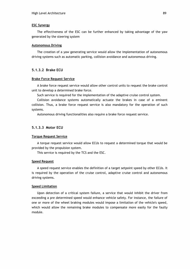
High Level Architecture 89
ESC Synergy
The effectiveness of the ESC can be further enhanced by taking advantage of the yaw
generated by the steering system
Autonomous Driving
The creation of a yaw generating service would allow the implementation of autonomous
driving systems such as automatic parking, collision avoidance and autonomous driving.
5.1.3.2 Brake ECU
Brake Force Request Service
A brake force request service would allow other control units to request the brake control
unit to develop a determined brake force.
Such service is required for the implementation of the adaptive cruise control system.
Collision avoidance systems automatically actuate the brakes in case of a eminent
collision. Thus, a brake force request service is also mandatory for the operation of such
systems.
Autonomous driving functionalities also require a brake force request service.
5.1.3.3 Motor ECU
Torque Request Service
A torque request service would allow ECUs to request a determined torque that would be
provided by the propulsion system.
This service is required by the TCS and the ESC.
Speed Request
A speed request service enables the definition of a target setpoint speed by other ECUs. It
is required by the operation of the cruise control, adaptive cruise control and autonomous
driving systems.
Speed Limitation
Upon detection of a critical system failure, a service that would inhibit the driver from
exceeding a pre determined speed would enhance vehicle safety. For instance, the failure of
one or more of the wheel braking modules would impose a limitation of the vehicle's speed,
which would allow the remaining brake modules to compensate more easily for the faulty
module.
90 Architecture Definition
5.1.3.4 Lights ECU
Emergency Light Activation
An emergency lights activation service would allow a safety enhancement of the vehicle
and its occupants. Several situations could lead to a request of this service:
Detection of a critical fault in any of the vehicle's systems, such as
braking, steering or propulsion systems
Emergency braking detected by the BA system
Impact detection
Collision avoidance system
5.1.3.5 Instrument Panel
Message Display Service
This service would offer the possibility of any ECU to display messages to the driver such
as diagnostics, notifications among others.
5.2 Braking System Architecture
This section presents the proposed braking architecture for a brake-by-wire system to be
developed in the EV project by students.
Commercial braking systems usually have all of the functionalities described on Chapter 2
implemented in a single ECU. A braking system encompassing all of the described
functionalities in a single ECU is considered to be an extremely complex system. Given the
impracticability of such a system to be developed by a single working group during the
duration of a semester, it was decided to grant each feature a dedicated control module as
Figure 5.2 depicts.
The presented architecture is conceived with the objective that any of the components
inserted in the architecture, cannot in any way cause the complete loss of the brakes or the
ability to provoke the loss of vehicle control.
Due to the fact that all elements belonging to the braking system are safety critical, all
modules are built with two redundant elements.
The brake pedal position module is responsible for the acquisition of the brake pedal
position sensors and the transmission of the brake pedal position over the network to the
interested entities.
Each wheel is provided with a brake actuator module, which receives the brake pedal
position from the brake pedal position module and braking requests from the ABS, TCS and
ESC modules, and command the actuators to generate the desired braking force.
The ABS, TCS and ESC modules capture wheel speed values made available by the wheel
speed acquisition module and the brake pedal position value, compute the required
interventions and, if necessary transmit braking requests to the brake actuator modules.
The gateway is the element responsible for providing the interface between the modules
and exterior systems. It enables outside systems to request braking services (ACC or
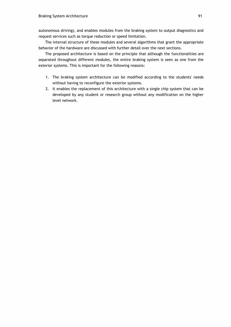
Braking System Architecture 91
autonomous driving), and enables modules from the braking system to output diagnostics and
request services such as torque reduction or speed limitation.
The internal structure of these modules and several algorithms that grant the appropriate
behavior of the hardware are discussed with further detail over the next sections.
The proposed architecture is based on the principle that although the functionalities are
separated throughout different modules, the entire braking system is seen as one from the
exterior systems. This is important for the following reasons:
1. The braking system architecture can be modified according to the students' needs
without having to reconfigure the exterior systems.
2. It enables the replacement of this architecture with a single chip system that can be
developed by any student or research group without any modification on the higher
level network.
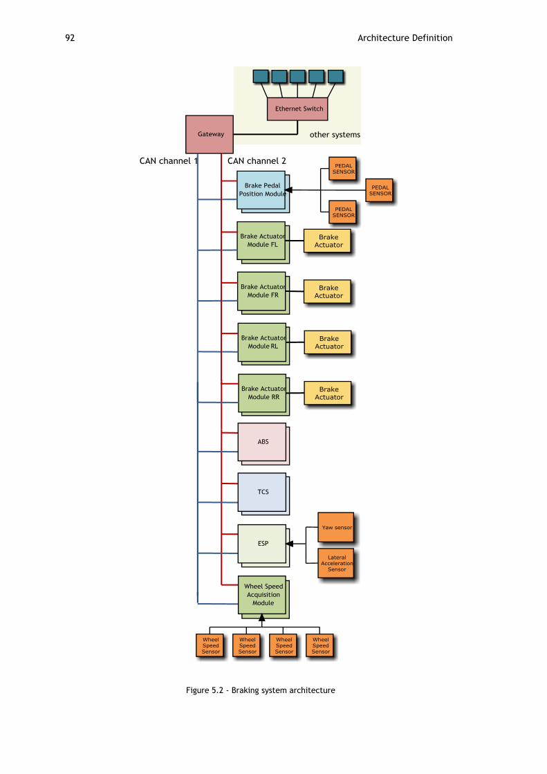
92 Architecture Definition
Figure 5.2 - Braking system architecture

Braking System Architecture 93
5.2.1 Braking Architecture Network Proposal
When implemented in a single ECU and due to hard real time requirements, braking
functionalities must be scheduled by a real time operating system. By having them distributed
into different hardware modules it is not enough to provide a real time operating system for
ensuring deterministic responses. The communication network must be itself deterministic,
otherwise it can jeopardize the efficiency of distributed control algorithms and the meeting
of hard real time deadlines.
Choosing an appropriate network for the braking system requires a deep study of each
individual feature to be carried, so that timing requirements can be specified. Due to the fact
that this work serves as the first introduction to the EV project, the requirements for these
systems are not yet known. Therefore, at this moment it is impossible to ensure that the
proposed networking solution is able to meet the timing requirements of such functionalities.
Given the impossibility of taking the functionalities' timing requirements into account, the
specification of the networking solution uniquely considers the feasibility of this architecture.
As it was discussed in Chapter 3, deterministic, multi-channel and high speed network
would be required for the braking system, such as Flexray, TTP/C, or TTEthernet. However,
given its cost and the required time for students to get familiarized with such protocols, it is
not realistic to propose such solutions. Despite a detailed study on the timing constraints of
each feature being required, CAN appears to be a good networking solution to be applied in
this academic project for the following reasons:
It enables the definition of priorities between messages
It is possible to guarantee the scheduling of periodic messages
It is taught on the available courses
It is present in many low cost microcontrollers available in the market
It is a widely adopted solution in the automotive industry for control
applications - proven efficiency
It provides a low cost implementation
It is robust
However, safety critical elements cannot be dependent on a single transmission medium,
as its failure would lead to the loss of the brakes. Therefore, it was decided to provide the
proposed architecture with redundant transmission mediums.
5.2.2 Gateway
The internal structure of the gateway is illustrated on Figure 5.3. The gateway is divided
into three distinct modules: the main element, and elements 1 and 2. Units shall be
connected internally by means of dedicated transmission channels as Figure 5.3 suggests.

94 Architecture Definition
Figure 5.3 - Gateway
The main element is responsible for routing messages between the exterior systems and
the braking modules, by means of elements 1 and 2.
Elements 1 and 2 are responsible for providing the interface between the main element
and the braking system modules. The introduction of elements 1 and 2 prevent that a single
unit connected to both communication channels can cause both network channels to fail,
which would result in brake loss.
5.2.2.1 Routing Messages From Exterior Systems
Upon arrival of an Ethernet package into the main element, the main element has the
task of transmitting its content to elements 1 and 2, which in turn will transmit the content
as CAN messages to the respective CAN channel. All messages transmitted by the main
element to Elements 1 and 2 shall be provided with error detection mechanisms, to prevent
that a faulty main element can cause elements 1 and 2 to jam both CAN channels.
The format of incoming messages from exterior systems can assume two distinct forms.
The first, consists in embedding CAN messages inside Ethernet frames. This enables the
main element to extract the CAN frame from the received Ethernet frame, and transmit it
directly to elements 1 and 2. This approach requires the assignment of CAN identifiers to be
done globally.
The second method consists on having transmitters to send data encapsulated into pure
Ethernet frames. Upon reception of an Ethernet package, the main element is required to
assign an identifier to the received data according to its content, and transmit it to elements
1 or 2.
5.2.2.2 Routing Messages from the Braking Systems
Due to the fact that not all frames exchanged in channels 1 and 2 are to be delivered to
exterior systems, elements 1 and 2 require the knowledge of the frames that must be
delivered to exterior systems, to after transmit them to the main element.
Messages transmitted by elements 1 and 2 can arrive to the main element in distinct time
instants. Therefore, a time frame in which messages are considered to be valid must be
defined. This prevents that a safety procedure might be engaged in case of transient faults.

Braking System Architecture 95
Figure 5.4 -Time frame of messages delivered to the main element
Upon reception of a frame from elements 1 or 2, the main element shall start counting
the time frame. If the second frame is received in the mean time or the time window expires,
the main element proceeds the transmission to the Ethernet segment according to Table 5.5.
Table 5.5 - Output of the main element according to incoming messages
Element 1 Element 2 Main element
Output
𝐶𝐴 𝐶𝐴 𝐶𝐴
𝐶𝐴 𝐼 𝐶𝐴
𝐼 𝐶𝐴 𝐶𝐴
𝐼 𝐼 𝐹𝑎𝑢𝑙𝑡 𝑑𝑖𝑎𝑔𝑛𝑜𝑠𝑖𝑠
𝐶𝐴 𝐶𝐵 𝐹𝑎𝑢𝑙𝑡 𝑑𝑖𝑎𝑔𝑛𝑜𝑠𝑖𝑠
where:
𝐶𝐴 , 𝐶𝐵 : 𝑒𝑟𝑟𝑜𝑟 𝑓𝑟𝑒𝑒 𝑚𝑒𝑠𝑠𝑎𝑔𝑒
𝐼: 𝑒𝑟𝑟𝑜𝑛𝑒𝑜𝑢𝑠 𝑜𝑟 𝑛𝑢𝑙𝑙 𝑚𝑒𝑠𝑠𝑎𝑔𝑒
5.2.3 Brake Pedal Position Module
The brake pedal position module consists of two elements which operate independently
and synchronized. Each brake pedal position unit has the task of acquiring the value of a
redundant set of brake pedal position sensors, compute one value out of the measured values
by means of a software voting mechanism, and output the brake pedal position to the
interested entities. The brake pedal position shall be sent periodically, so faults within this
module can be detected by other units. Despite in Figure 5.2 and Figure 5.5 three sensors are
represented, any number of sensors can be connected to ensure the desired level of
dependability and any of the techniques presented on Chapter 4 can be applied.

96 Architecture Definition
Figure 5.5 - Brake pedal position module
5.2.3.1 The Necessity of Synchronism
If both elements operate unsynchronized it can happen that the sampled value of the
sensors can differ significantly, as Figure 5.6 illustrates. The faster the driver presses or
releases the brake pedal, the higher the difference will be.
Fault tolerant software mechanisms that operate in the brake actuator modules can
interpret the difference between both values as a fault, with the aggravation of being unable
to distinguish which of the elements is providing the erroneous value. In such a situation, the
brake output module would not be able to perform a correct decision on the brake force to
produce.
Figure 5.6 - Unsynchronized units
By synchronizing the acquisition time between both units, the system minimizes the
deviation between the acquired values in both units.
A Simple Synchronism Method
A simple synchronism method which can be easily built by students, only requiring two
digital ports on the microcontroller and two wires connected as Figure 5.7 illustrates.
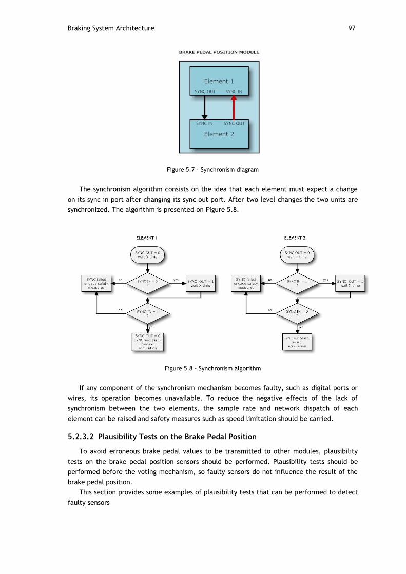
Braking System Architecture 97
Figure 5.7 - Synchronism diagram
The synchronism algorithm consists on the idea that each element must expect a change
on its sync in port after changing its sync out port. After two level changes the two units are
synchronized. The algorithm is presented on Figure 5.8.
Figure 5.8 - Synchronism algorithm
If any component of the synchronism mechanism becomes faulty, such as digital ports or
wires, its operation becomes unavailable. To reduce the negative effects of the lack of
synchronism between the two elements, the sample rate and network dispatch of each
element can be raised and safety measures such as speed limitation should be carried.
5.2.3.2 Plausibility Tests on the Brake Pedal Position
To avoid erroneous brake pedal values to be transmitted to other modules, plausibility
tests on the brake pedal position sensors should be performed. Plausibility tests should be
performed before the voting mechanism, so faulty sensors do not influence the result of the
brake pedal position.
This section provides some examples of plausibility tests that can be performed to detect
faulty sensors
98 Architecture Definition
Range Testing
Range testing relies on the fact that the brake pedal position must be within a range of
plausible values. For instance, if it is considered a depressing value between 0 and 100
percentage, a negative value or a value above 100 would indicate a erroneous operation.
Furthermore, if for instance the analog to digital converter responsible for acquiring the
sensor values with a 10 bit resolution, values higher than 1023 would also indicate a
erroneous operation.
Derivative Testing
Derivative testing relies on the dynamics of the driver pressing the pedal. The pressing of
a brake pedal follows a natural curve, with a maximum physical variation. If the rate of
variation is exceeded it might indicate an erroneous value and the value provided by the
sensor can be excluded.
Figure 5.9 - Brake pedal depression dynamics
Threshold Testing
A threshold test can be applied for the exclusion of faulty sensors in the following way:
1. Calculate the average/median of all sensor acquisition values
2. If one sensor differs from a predetermined amount from the average/median, this
sensor is excluded and marked as faulty
5.2.3.3 Elements Operation
The operation of the braking system cannot be dependent on a single brake pedal
element, as its failure leads to the loss of brakes. Hence, it is advisable to provide each
element with self checking mechanisms. Whenever it is considered that an element is faulty,
the driver must be notified and vehicle's speed should be limited.
It should be noted that as both elements operate independently, it is possible that both
can transmit different brake pedal positions. However, as it was mentioned, the dynamics of
a driver pressing or releasing the brake pedal follows a natural curve, and therefore, the
receiving modules can detect and choose which value is plausible by performing the
appropriate tests, and after notify the driver and request for vehicle's speed limitation.
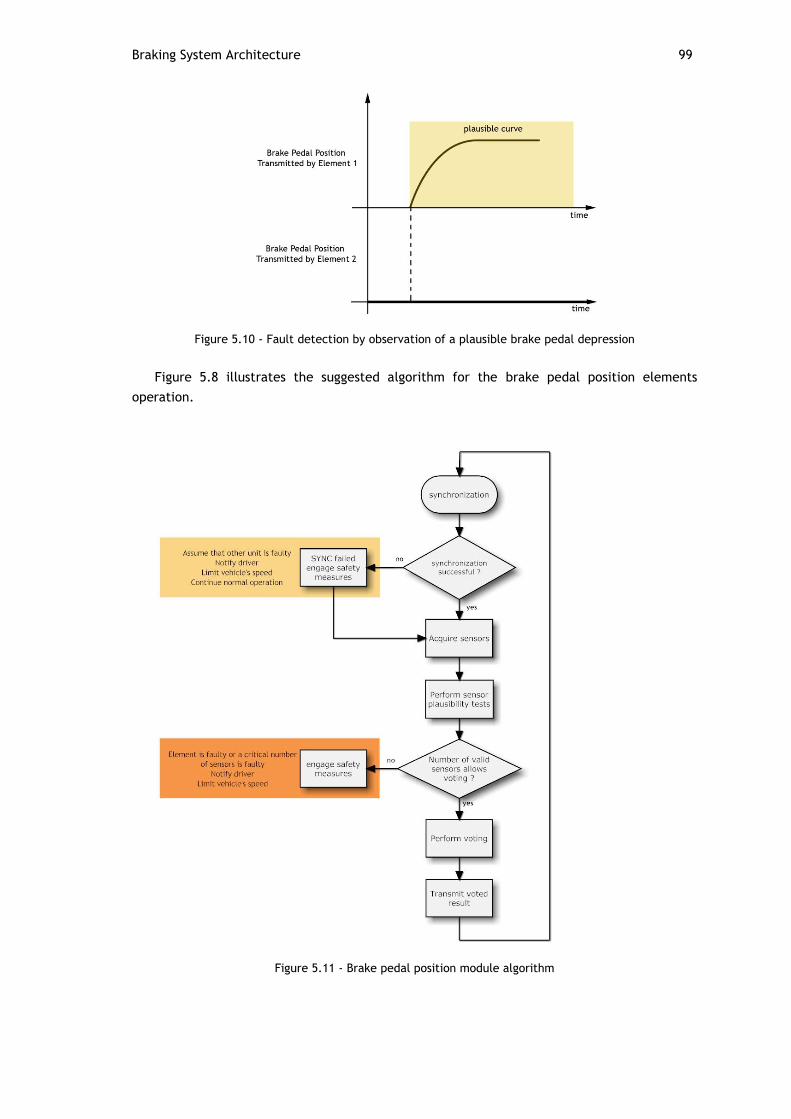
Braking System Architecture 99
Figure 5.10 - Fault detection by observation of a plausible brake pedal depression
Figure 5.8 illustrates the suggested algorithm for the brake pedal position elements
operation.
Figure 5.11 - Brake pedal position module algorithm

100 Architecture Definition
5.2.4 Wheel Speed Acquisition Module
It would not be practical to connect wheel speed sensors to all of the requiring
functionalities. Therefore, a extra unit named wheel speed acquisition module was added.
Wheel speed values are made available in the network channels by this module.
The calculation of vehicle dynamics taking as basis erroneous wheel speeds values may
affect the stability of the vehicle as the ABS, TCS and ESC systems can perform erroneous
brake requests taking as basis wrong wheel speed values. Therefore, it must be granted that
wheel speed values are always correct, or no wheel speed values are transmitted over the
network.
Many of the architectures and philosophies presented in Chapter 4 can be used to
overcome this issue. The simpler method consists on the replication in a duplication with
comparison topology of the computational elements of the wheel speed acquisition module.
This method consists on having two redundant units performing the same operations and
comparing results. If a disagreement between the two units is found, the entire module is
considered as faulty. Upon this situation, diagnostic messages would be sent by the error
detecting unit(s) and their operation would be ceased.
Figure 5.12 - Wheel speed acquisition module
To ensure that the transmitted wheel speed values are always correct, the wheel speed
acquisition module should be composed by two elements which compute the values of wheel
speed sensors at the same instants, perform plausibility tests on the acquired sensor values,
and exchange the values with the other redundant unit. Congruence tests have to be made to
check whether the values acquired by both elements are in consonance. This can be done by
means of threshold tests, which check whether the differences between wheel speeds vary
from a determined range which is considered faulty. If congruence is verified, a voting
mechanism is performed between the two units so the same wheel speed values are
transmitted to the respective CAN channels.
Similarly to what was discussed for the brake pedal position module, wheel speed sensors
require redundancy so faults within a sensor can be detected or compensated.
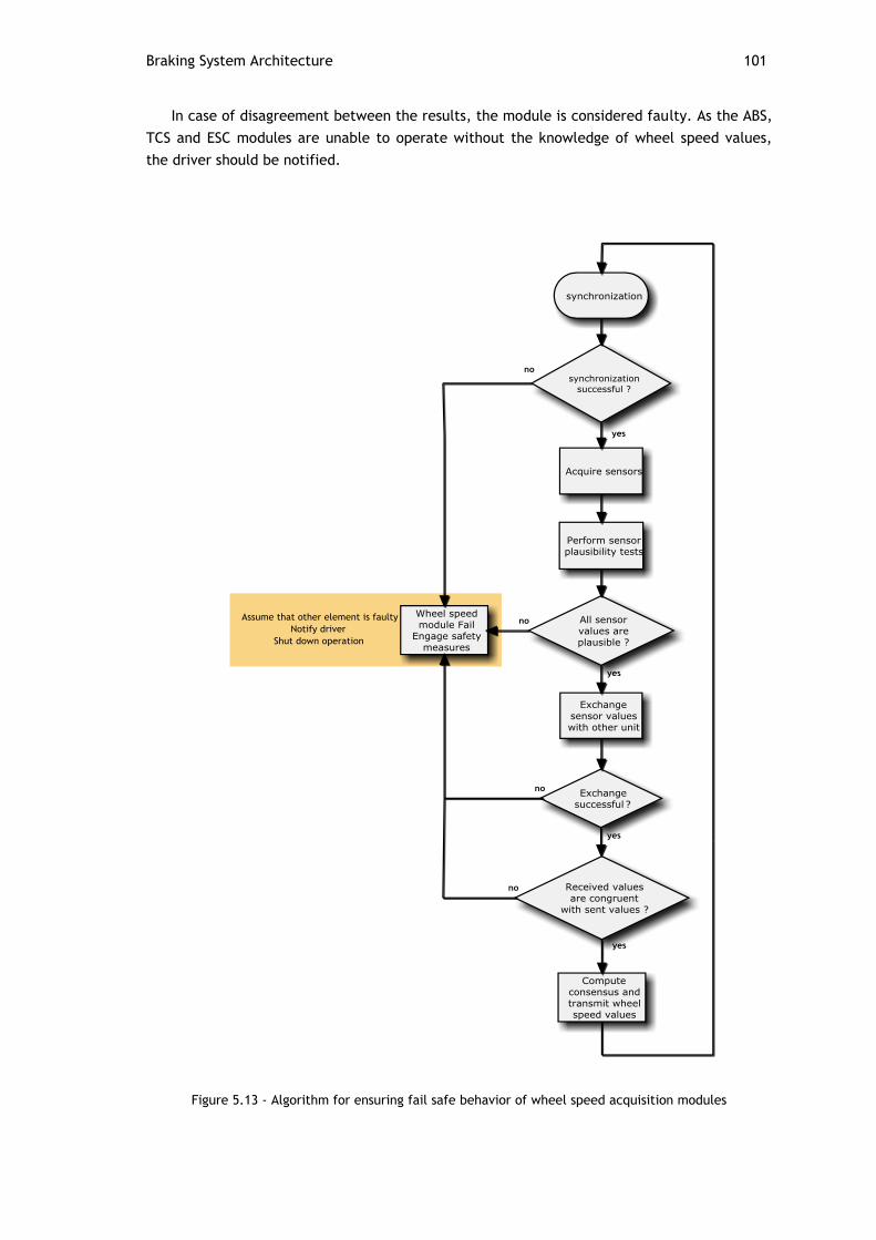
Braking System Architecture 101
In case of disagreement between the results, the module is considered faulty. As the ABS,
TCS and ESC modules are unable to operate without the knowledge of wheel speed values,
the driver should be notified.
Figure 5.13 - Algorithm for ensuring fail safe behavior of wheel speed acquisition modules
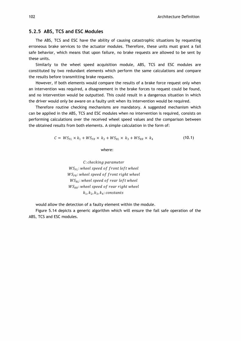
102 Architecture Definition
5.2.5 ABS, TCS and ESC Modules
The ABS, TCS and ESC have the ability of causing catastrophic situations by requesting
erroneous brake services to the actuator modules. Therefore, these units must grant a fail
safe behavior, which means that upon failure, no brake requests are allowed to be sent by
these units.
Similarly to the wheel speed acquisition module, ABS, TCS and ESC modules are
constituted by two redundant elements which perform the same calculations and compare
the results before transmitting brake requests.
However, if both elements would compare the results of a brake force request only when
an intervention was required, a disagreement in the brake forces to request could be found,
and no intervention would be outputted. This could result in a dangerous situation in which
the driver would only be aware on a faulty unit when its intervention would be required.
Therefore routine checking mechanisms are mandatory. A suggested mechanism which
can be applied in the ABS, TCS and ESC modules when no intervention is required, consists on
performing calculations over the received wheel speed values and the comparison between
the obtained results from both elements. A simple calculation in the form of:
𝐶 = 𝑊𝑆𝐹𝐿 × 𝑘1 + 𝑊𝑆𝐹𝑅 × 𝑘2 + 𝑊𝑆𝑅𝐿 × 𝑘3 + 𝑊𝑆𝑅𝑅 × 𝑘4
where:
𝐶: 𝑐𝑒𝑐𝑘𝑖𝑛𝑔 𝑝𝑎𝑟𝑎𝑚𝑒𝑡𝑒𝑟
𝑊𝑆𝐹𝐿 : 𝑤𝑒𝑒𝑙 𝑠𝑝𝑒𝑒𝑑 𝑜𝑓 𝑓𝑟𝑜𝑛𝑡 𝑙𝑒𝑓𝑡 𝑤𝑒𝑒𝑙
𝑊𝑆𝐹𝑅 : 𝑤𝑒𝑒𝑙 𝑠𝑝𝑒𝑒𝑑 𝑜𝑓 𝑓𝑟𝑜𝑛𝑡 𝑟𝑖𝑔𝑡 𝑤𝑒𝑒𝑙
𝑊𝑆𝑅𝐿 : 𝑤𝑒𝑒𝑙 𝑠𝑝𝑒𝑒𝑑 𝑜𝑓 𝑟𝑒𝑎𝑟 𝑙𝑒𝑓𝑡 𝑤𝑒𝑒𝑙
𝑊𝑆𝑅𝑅 : 𝑤𝑒𝑒𝑙 𝑠𝑝𝑒𝑒𝑑 𝑜𝑓 𝑟𝑒𝑎𝑟 𝑟𝑖𝑔𝑡 𝑤𝑒𝑒𝑙
𝑘1, 𝑘2, 𝑘3 ,𝑘4: 𝑐𝑜𝑛𝑠𝑡𝑎𝑛𝑡𝑠
(10.1)
would allow the detection of a faulty element within the module.
Figure 5.14 depicts a generic algorithm which will ensure the fail safe operation of the
ABS, TCS and ESC modules.
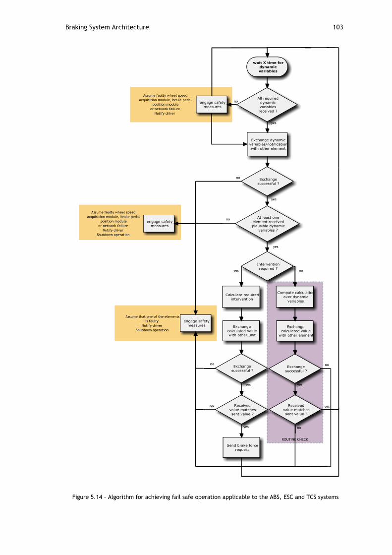
Braking System Architecture 103
Figure 5.14 - Algorithm for achieving fail safe operation applicable to the ABS, ESC and TCS systems

104 Architecture Definition
5.2.6 Braking Actuator Modules
Braking actuator modules are responsible for receiving braking requests and effectively
actuate the brakes to generate the required braking force. Brake requests are received
periodically by the brake pedal module, and sporadically by other units such as the ESC, ABS,
TCS, ACC and other implemented systems as required. Several brake requests can be sent at
the same instants by these units. Such issues have to be dealt with appropriate software
specification.
5.2.6.1 The Safe State of a Brake Actuator
The braking actuator modules are responsible for actuating directly on the brake
actuators. Although it was mentioned in Chapter 4 that a brake-by-wire system does not have
a safe state, the difference between the safe state of the entire braking system and a single
brake actuator must be understood.
When designing fault tolerant architectures, one of the most important things is that its
safety must be self-sustainable. Thus, during this discussion we exclude the hypothesis of
intervention from the Electronic Stability Program in case of vehicle destabilization provoked
by erroneous brake actuation.
A faulty braking actuator module can cause two distinct situations: performing an
unsolicited brake force and the contrary, not performing a solicited brake force. The former
situation can lead to catastrophic situations such as the loss of vehicle control, as the
creation of an unsolicited brake force creates an undesired yaw moment. In case of
occurrence of the latter situation, a yaw moment is also generated but with the advantage
that the effects of a non braking wheel can be detected and compensated. It must be kept in
mind that brake compensation can only be performed up to a certain brake force. However, if
we consider that the odds of a brake actuator failing at the same instant that the driver
performs an emergency braking, the non braking state can be considered the safe state of a
braking actuator.
Figure 5.15 - Erroneous operation of the brake actuator

Braking System Architecture 105
5.2.6.2 Braking Actuator Modules Operation
Similarly to the wheel speed acquisition module, ABS, ESC and TCS modules, the brake
actuator modules are constituted by two elements working in a duplication with comparison
topology. Although both elements perform the same calculations, only one element
commands the actuator. Upon abnormal behavior from either the actuator or any of the
elements, the detecting element de-energizes the actuator and engages safety measures.
A more detailed view of the braking actuator modules and the interacting units is seen on
Figure 5.16.
Figure 5.16 - Detailed view of brake actuator module connections
Figure 5.17 depicts an algorithm that ensures the fail safe behavior of the brake actuator
modules when performing brake requests upon reception of the brake pedal position.
The algorithm for performing brake request from units such as the ABS, TCS and ESC is
similar to that described in Figure 5.17, but in case that both elements receive different
brake requests, the command shall be ignored as this implies that a fault has occurred in the
ABS, TCS or ESC modules. Upon such situation, a diagnostic message should be sent.

106 Architecture Definition
Figure 5.17 - Algorithm which ensures the fail safe of brake actuator elements

Braking System Architecture 107
5.2.6.3 Wrap Around Testing
Once the controller outputs the appropriate signal to generate a certain brake force, it
cannot be expected that the actuator will actually perform the desired brake force, as faults
can occur in the actuator and on the interfaces between the controller and the actuator.
Therefore, it must be tested at all times that the desired brake force is actually being
generated. This implies that there must any kind of feedback between the controlling and the
actuating units. On the impossibility of measuring the brake force directly, several indirect
analytical ways can be performed such as:
1. Measuring the current applied to the actuator (current proportional to torque)
2. Observing wheel speed when brakes are applied
The suggested algorithm is illustrated in Figure 5.18.
Figure 5.18 - Algorithm which checks if actuator behavior corresponds to desired behavior
5.2.7 Power Supplies
The connection of all controllers and actuating units on the braking system to the same
power supply would result in loss of the brakes in case of power outage. The ideal situation is
to provide each component of the system with a dedicated power supply. Due to unfeasibility
of such idea, due to cost, complexity and available space, and following the same philosophy
of reducing the number of components on the maximum while granting safety, the minimum
number of power supplies suggested is two.
Both elements from the brake pedal position module must be powered by different power
supplies, as the failure of a single power supply would lead to brake loss, given the inability
of the brake pedal position to be transmitted to the actuators.
Due to the fail safe behavior of the ABS, TCS, ESC and wheel speed acquisition modules,
these can be powered by the same supply, as a power outage on any of the elements will
cause the whole modules to stop working due to the comparison mechanisms for fault
detection.
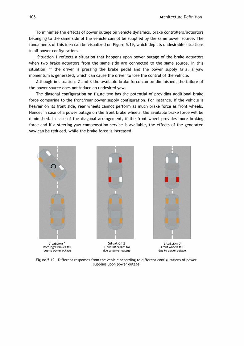
108 Architecture Definition
To minimize the effects of power outage on vehicle dynamics, brake controllers/actuators
belonging to the same side of the vehicle cannot be supplied by the same power source. The
fundaments of this idea can be visualized on Figure 5.19, which depicts undesirable situations
in all power configurations.
Situation 1 reflects a situation that happens upon power outage of the brake actuators
when two brake actuators from the same side are connected to the same source. In this
situation, if the driver is pressing the brake pedal and the power supply fails, a yaw
momentum is generated, which can cause the driver to lose the control of the vehicle.
Although in situations 2 and 3 the available brake force can be diminished, the failure of
the power source does not induce an undesired yaw.
The diagonal configuration on figure two has the potential of providing additional brake
force comparing to the front/rear power supply configuration. For instance, if the vehicle is
heavier on its front side, rear wheels cannot perform as much brake force as front wheels.
Hence, in case of a power outage on the front brake wheels, the available brake force will be
diminished. In case of the diagonal arrangement, if the front wheel provides more braking
force and if a steering yaw compensation service is available, the effects of the generated
yaw can be reduced, while the brake force is increased.
Figure 5.19 - Different responses from the vehicle according to different configurations of power supplies upon power outage

Braking System Architecture 109
5.2.8 Braking System Fault Analysis
This section provides a brief overview of the types of faults than can occur within the
braking system, the respective consequences and its effect on brake control. The following
tables summarize the concepts and ideas that have been discussed throughout this chapter.
Table 5.6 - Gateway fault analysis
Component Fault Consequence Brake loss
Main Element Component fail or power
outage
Braking system unable to interact
with exterior systems
TCS and ESC unable to operate
No
Erroneous messages
transmitted to elements 1
and 2
None: erroneous messages detected
by elements 1 and 2 and not
transmitted to braking modules
No
Elements 1 or 2 Component fail None: interaction with exterior
systems is done by means of non faulty
element
No
Power outage Braking system unable to interact
with exterior systems
TCS and ESC unable to operate
No
Table 5.7 - Network channels fault analysis
Component Fault Consequence Brake loss
CAN transmission
medium 1 or 2
Communication
channel mishap
None: units are able to
communicate by means of redundant
transmission medium
No
Network jam by any
unit connected to the
channel
None: units are able to
communicate by means of redundant
transmission medium
No

110 Architecture Definition
Table 5.8 - Brake pedal position fault analysis
Component Fault Consequence Brake loss
Element 1 or 2 Component fail None: brake pedal position is
transmitted by other element
No
Erroneous brake pedal
position transmitted
None: receiving modules detect
erroneous brake pedal position and
consider the value sent by the
redundant element
No
Power outage None: brake pedal position is
transmitted by redundant element
which is not affected by power
outage
No
Sensors Erroneous value
provided
None: fault detected by plausibility
tests or natural curve and masked by
voting mechanism
No
Table 5.9 - ABS, TCS and ESC modules fault analysis
Component Fault Consequence Brake loss
Element 1 or 2 Component fail Module unable to operate: detected
by redundant element
No
Erroneous brake request
transmitted
Required intervention not performed:
brake actuator modules detect
discrepancy between the two received
brake requests and do not perform any
intervention (very unlikely due to
routine checks)
No
Power outage Module unable to operate No
Table 5.10 - Brake actuator modules fault analysis
Component Fault Consequence Brake loss
Element 1 or 2 Component fail Loss of brake force provided by the
controlled actuator: detected by
redundant element, which can request
brake compensation
Limited
Power outage Loss of brake force provided by the
controlled actuator Limited
Brake Actuator Component fail Loss of brake force provided by the
actuator: erroneous behavior detected by
brake actuator elements and actuator de-
energized
Limited

Braking System Architecture 111
Table 5.11 - Wheel speed acquisition module fault analysis
Component Fault Consequence Brake loss
Element 1 or 2 Component fail ABS, TCS and ESC unable to operate:
detected by redundant element
No
Erroneous wheel speed
values calculated
ABS, TCS and ESC unable to operate:
detected by redundant element
No
Erroneous wheel speed
values transmitted
None: ABS, TCS and ESC modules
detect discrepancy between the two
received values
No
Power outage ABS, TCS and ESC unable to operate No
Wheel speed sensors Erroneous value provided ABS, TCS and ESC unable to operate No: fault detected
by plausibility
tests or natural
curve and masked
by voting
mechanism
Table 5.12 - Power supply fault analysis
Component Fault Consequence Brake loss
Power Supply Component fail All elements connected to power supply
fail
Loss of brake force provided by actuators
powered by the faulty power supply
Limited

112 Architecture Definition

113
Chapter 6
Conclusions and Future Work
6.1 Conclusions
Throughout this work, several functionalities that are usually found in modern vehicles
and which have the potential to be developed along the various courses available have been
identified, and their operation and hardware architectures have been documented. Despite
the intent of providing this document with more information about the computational
platforms that are used by manufacturers to implement the described features, the lack of
information resulting from the fact that such information represent trade secrets, made it
impossible for providing this document with such data.
The most widely used communication networks in the automotive industry have been
studied and documented, which will allow students to understand the concepts and their
applicability on the projects that will be developed. Although TTEthernet is not actually used
in the automotive industry, its capabilities and features granted it a spot in this document
due to its potential of becoming the future solution for the problems that the new generation
of vehicles will face.
During this study, it was found that many efforts are being put together by manufacturers
for the implementation of drive-by-wire systems. Although it was not on the objectives of this
work, it is my belief that this document would be incomplete without a brief reference to the
concepts of this emergent philosophy. Not only the drive-by-wire systems were referenced,
but also some guidelines and techniques that will enable students to develop their own
solutions.
The architecture and ideas that were proposed in Chapter 5 for the braking system,
enables that a system which is usually integrated in a single module to be developed by
several working groups. Despite being conceptualized taking as basis a network protocol that
was not designed with the intent of being implemented for safety critical applications, the
proposed architecture and algorithms that support its operation are able to achieve a fair
amount of dependability, which is required for a system whose malfunction can lead to
catastrophic consequences.

114 Conclusions and Future Work
6.2 Future Work
As it was mentioned in Chapter 5, Ethernet as a the communications backbone for the EV
does not guarantee in any way the desired level of determinism which is required for the
distributed control algorithms that will depend on it. This issue could be solved by the
creation of a middleware layer that would allow the different systems within the vehicle to
exchange data in a TDMA scheme, based on the Ethernet infrastructure.
The proposed architecture for the braking system requires a detailed study on the timing
requirements of each feature, so the schedulability of all the messages that are expected to
travel within both CAN channels can be proved.
Being the EV an academic project, it is expected that the architecture of the systems
installed will change over time. To avoid constant reconfigurations on the devices that are
expected to communicate, a middleware layer which would hide the details of the hardware
architecture would be a valuable asset.

115
References
[1] V. Peter, V. Joeri and M. Gaston. "Practical Infrastucture Development For Electric
Vehicles In Brussels Capital Region". Available:
http://etecmc10.vub.ac.be/etecphp/publications/evs19vdb2.pdf. Access date:
January 2011
[2] U.S. Department of Energy. "Electric Vehicles". Available:
http://www1.eere.energy.gov/vehiclesandfuels/pdfs/basics/jtb_electric_vehicle.pdf
. Access Date: Janurary 2010
[3] M. Eberhard and M. Tarpenning, "The 21st Century Electric Car". Available:
http://www.veva.bc.ca/wtw/Tesla_20060719.pdf. January 2011.
[4] European Comission. "The EU climate and energy package". Available:
http://ec.europa.eu/clima/policies/brief/eu/package_en.htm. Access date: January
2011
[5] United States Environmental Protection Agency, "Clean Alternative Fuels: Electric
Vehicles". Available:
http://www.epa.gov/oms/consumer/fuels/altfuels/420f00034.pdf. Access date:
January 2011.
[6] N. Navet and F. Simonot-Lion, "Automotive Embedded Systems Handbook," in Vehicle
Functional Domains and Their Requirements, 1st Edition, CRC Press, 2009.
[7] T. Nolte, "Share-Driven Scheduling of Embedded Networks," doctoral dissertation,
Department of Computer Science and Electronics, Malardalen University, Vasteras,
Sweden, May 2006.
[8] C. Kahane and J. Dang, "The Long-Term Effect of ABS in Passenger Cars and LTVs".
Available http://www-nrd.nhtsa.dot.gov/Pubs/811182.pdf. Access date: January
2011.
[9] W. Ribbens, "Understanding Automotive Electronics," in Vehicle Motion Control, 6th
Edition, Newnes, 1998.
[10] A. Mirzaei, M. Moallem, B. M. Dehkordi, and B. Fahimi, "Design of an Optimal Fuzzy
Controller for Antilock Braking Systems," Vehicular Technology, IEEE Transactions on,
vol. 55, 2006.
[11] Robert Bosch, "Automotive Handbook", 5th Edition,Bentley Publishers, 2000.
[12] A. D. David Burton, Stuart Newstead, David Logan, Brian Fildes, "Effectiveness of ABS
and Vehicle Stability Control Systems." Available:
http://www.monash.edu.au/muarc/reports/Other/RACV%20ABS%20braking%20system
%20effectiveness.pdf. Access date: January 2011.
[13] D. Song, J. Li, Z. Ma, Y. Li, J. Zhao, and W. Liu, "Application of CAN in vehicle
traction control system," in Vehicular Electronics and Safety, 2005. IEEE International
Conference, 2005.
[14] J. Dang, "Statistical Analysis of the Effectiveness of Electronic Stability Control (ESC)
Systems - Final Report". Available: http://www-nrd.nhtsa.dot.gov/Pubs/810794.pdf.
Access date: January 2011.
116 References
[15] J. Li and J. Wang, "Research on the automotive EBD system based on fuzzy control,"
in Computer Engineering and Technology (ICCET), 2010 2nd International Conference,
2010.
[16] C. Lampton. "How Electronic Brake Force Distribution Works". Available:
http://auto.howstuffworks.com/car-driving-safety/safety-regulatory-
devices/electronic-brake-force-distribution.htm. Access date: January 2011.
[17] Volkswagen, "The Brake Assist System." Available:
http://www.volkspage.net/technik/ssp/ssp/SSP_264_d1.pdf. Access date: January
2011.
[18] Institute of road safety research, "Speed choice: the influence of human, vehicle, and
road". Available: http://www.swov.nl/rapport/Factsheets/UK/FS_Speed_choice.pdf.
Access date: January 2011.
[19] X. Li, X. Zhao, and J. Chen, "Controller Design for Electric Power Steering System
Using T-S Fuzzy Model Approach". Available:
http://www.ijac.net/qikan/manage/wenzhang/2008-066.pdf. Access date: January
2011.
[20] K. Nice. "How Car Steering Works". Available:
http://auto.howstuffworks.com/steering2.htm. Access date: January 2011.
[21] J. Reimpell, H. Stoll, and J. Betzler, "The Automotive Chassis: Enginerring Principles",
2nd Edition, SAE International, 2001.
[22] Z. Hui, Z. Yuzhi, L. Jinhong, R. Jing, and G. Yongjun, "Modeling and characteristic
curves of electric power steering system," in Power Electronics and Drive Systems,
2009. PEDS 2009. International Conference, 2009.
[23] A. W. Burton, "Innovation drivers for electric power-assisted steering," Control
Systems Magazine, IEEE, vol. 23.
[24] Volkswagen of America, "Electro-mechanical Power Steering". Available:
http://tos.pp.fi/koukku/892403.pdf. Access date: January 2011.
[25] C. Min Wan, P. Jun Seok, L. Bong Soo, and L. Man Hyung, "The performance of
independent wheels steering vehicle(4WS) applied Ackerman geometry," in Control,
Automation and Systems, 2008. ICCAS 2008. International Conference, 2008.
[26] D. Wickell. "Facts About Four Wheel Steering". Available:
http://trucks.about.com/cs/4ws/a/4wheel_steering.htm. Access Date: January 2011.
[27] M. Gutierrez. "4 Wheel Steering". Available: http://ezinearticles.com/?4-Wheel-
Steering&id=4117270. Access date: January 2011.
[28] P. Brabec, M. Malý, and R. Vozenílek, "Controls system of vehicle model with four
wheel steering (4WS)."
[29] E. Grabianowski. "How the Jeep Hurricane Works". Available:
http://auto.howstuffworks.com/jeep-hurricane2.htm. Access date: January 2011.
[30] C. Binggang, B. Zhifeng, and Z. Wei, "Research on control for regenerative braking of
electric vehicle," in Vehicular Electronics and Safety, 2005. IEEE International
Conference, 2005.
[31] M. Ehsani, Y. Gao, S. Gay, and A. Emadi, "Modern Electric, Hybrid Electric and Fuel
Cell Vehicles", CRC press, 2005.
[32] W. Pananurak, S. Thanok, and M. Parnichkun, "Adaptive cruise control for an
intelligent vehicle," in Robotics and Biomimetics, 2008. ROBIO 2008. IEEE
International Conference, 2009.
[33] "Denso Automotive Products". Available:
http://www.globaldensoproducts.com/dcs/accs/. Access date: January 2011.
[34] N. Navet, Y. Song, F. Simonot-Lion, and C. Wilwert, "Trends in Automotive
Communication Systems," Proceedings of the IEEE, vol. 93, 2005.
[35] S. C. Talbot and R. Shangping, "Comparision of FieldBus Systems CAN, TTCAN, FlexRay
and LIN in Passenger Vehicles," in Distributed Computing Systems Workshops, 2009.
ICDCS Workshops '09. 29th IEEE International Conference, 2009.
[36] T. Hansson and L. Bello, "Implementing Next Generation Automotive
Communications," Proceedings of the 1st Embedded Real-Time Systems
Implementation Workshop (ERTSI'04) in conjunction with the 25th IEEE International
Real-Time Systems Symposium (RTSS'04), December 2004.
References 117
[37] G. Cena, A. Valenzano, and S. Vitturi, "Advances in automotive digital
communications," Computer Standards & Interfaces, Volume 27, Issue 6, June 2005.
[38] D. Paret, "Multiplexed Networks for Embedded Systems," in Time-Triggered Protocols
- Flexray, Wiley, 2007.
[39] T. Nolte, H. Hansson, and L. L. Bello, "Automotive communications-past, current and
future," in Emerging Technologies and Factory Automation, 2005. ETFA 2005. 10th
IEEE Conference, 2005.
[40] CiA, "CAN Specification 2.0 Part B". Available: http://www.can-cia.org. Access date:
January 2011.
[41] C. Temple, "Flexray International Workshop Protocol Overview: presentation".
Available: http://www.flexray.com/products/protocol%20overview.pdf. Access date:
January 2011.
[42] Flexray Consortium, "Flexray Communications System Protocol Specification Version
2.1". Available: http://www.flexray.com. Access date: January 2011.
[43] Native Instruments, "FlexRay Automotive Communication Bus Overview". Available:
http://zone.ni.com/devzone/cda/tut/p/id/3352. Access date: January 2011.
[44] Lin Consortium, "Lin Specification package 2.0". Available: http://www.lin-
subbus.org/. Access date: January 2011.
[45] TTTech, "TTEthernet - A Powerful Network Solution for All Purposes". Available:
http://www.tttech.com/fileadmin/content/white/TTEthernet/TTEthernet_Article.pd
f. Access date: 2011.
[46] TTTech, "TTEthernet Specification". Available: http://wwww.tttech.com. Access
date: January 2011.
[47] M. Bertoluzzo, P. Bolognesi, O. Bruno, G. Buja, A. Landi, and A. Zuccollo, "Drive-by-
wire systems for ground vehicles," in Industrial Electronics, 2004 IEEE International
Symposium, 2004.
[48] Citroën. "Citroën C5 by wire demonstration vehicle". Available:
http://www.citroenet.org.uk/passenger-cars/psa/c5/c5bywire.html. Access date:
January 2011.
[49] T. Harris. "How GMs Hy-wire Works". Available: http://auto.howstuffworks.com/hy-
wire1.htm. Access date: January 2011.
[50] F. Seidel, "X-by-Wire". Available: http://osg.informatik.tu-
chemnitz.de/lehre/old/ws0809/sem/online/x-by-wire.pdf. Access date: January
2011.
[51] E. A. Bretz, "By-wire cars turn the corner," Spectrum, IEEE, vol. 38, 2001.
[52] Jason. "NHTSA Says Can't Find Flaw In Toyota Electronic Throttle, Calls AS".
Available: http://www.torrancetoyotaservice.com/2010/07/02/nhtsa-says-cant-find-
flaw-in-toyota-electronic-throttle-calls-nas/. Access date: December 2010.
[53] J. Fuller. "How Drive-by-wire Technology Works". Available:
http://auto.howstuffworks.com/car-driving-safety/safety-regulatory-devices/drive-
by-wire2.htm. Access date: January 2011.
[54] Weidong Xiang; Richardson, P.C.; Chenming Zhao; Mohammad, S.; , "Automobile
Brake-by-Wire Control System Design and Analysis,"Vehicular Technology, IEEE
Transactions on , vol.57, no.1, Jan 2008.
[55] Auto Spectator. "Continental Steps Up Engineering on Electromechanical Brakes".
Available: http://www.autospectator.com/cars/automotive-oems/0038720-
continental-steps-engineering-electromechanical-brakes. Access date: January 2011.
[56] C. Wilwert, N. Navet, Y. Song, and F. Simonot-Lion, "Design of automotive X-by-Wire
systems".
[57] N. Storey, "Safety-Critical Computer Systems," in Fault Tolerance, 1st Edition, Addison
Wesley, 1996.
[58] International Organization for Standardization, "Road vehicles - Functional safety."
[59] X-by-wire Consortium, "X-By-Wire: Safety Related Fault Tolerant Systems in Vehicles,"
November 1998.
[60] H. Kirrmann, "Fault Tolerant Computing in Industrial Automation," in Fault-tolerant
Computers, 2nd Edition, ABB Research Center, 2005.

118 References
[61] A. Goel and A. Sharma. "Dual core architectures in automotive SoCs". Available:
http://www.eetimes.com/design/automotive-design/4206395/Dual-core-
architectures-in-automotive-SoCs?pageNumber=1. Access date: January 2011.
[62] M. Baumeister, "Using Decoupled Parallel Mode for Safety Applications". Available:
http://cache.freescale.com/files/32bit/doc/white_paper/MPC564XLWP.pdf. Access
date: January 2011.
[63] Freescale Semiconductor, "MPC5643L Microcontroller Data Sheet."