controle motor de passo microcontrolador
28
MIE443 DISPENSING ROBOT PROTOTYPE TECHNICAL MANUAL AND DATA SHEET MIE443- Dispensing Robot Prototype TECHNICAL MANUAL AND DATA SHEET
Transcript of controle motor de passo microcontrolador
8/7/2019 controle motor de passo microcontrolador
http://slidepdf.com/reader/full/controle-motor-de-passo-microcontrolador 1/28
MIE443 DISPENSING ROBOT PROTOTYPE TECHNICAL MANUAL AND DATA SHEET
MIE443- Dispensing Robot Prototype
TECHNICAL MANUAL AND DATA SHEET
8/7/2019 controle motor de passo microcontrolador
http://slidepdf.com/reader/full/controle-motor-de-passo-microcontrolador 2/28
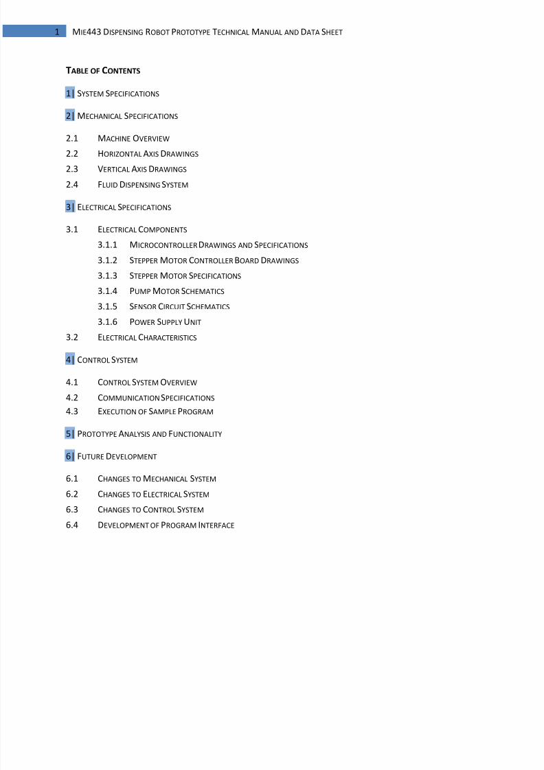
1 MIE443 DISPENSING ROBOT PROTOTYPE TECHNICAL MANUAL AND DATA SHEET
TABLE OF CONTENTS
1| SYSTEM SPECIFICATIONS
2| MECHANICAL SPECIFICATIONS
2.1 MACHINE OVERVIEW
2.2 HORIZONTAL AXIS DRAWINGS
2.3 VERTICAL AXIS DRAWINGS
2.4 FLUID DISPENSING SYSTEM
3| ELECTRICAL SPECIFICATIONS
3.1 ELECTRICAL COMPONENTS
3.1.1 MICROCONTROLLER DRAWINGS AND SPECIFICATIONS
3.1.2 STEPPER MOTOR CONTROLLER BOARD DRAWINGS
3.1.3 STEPPER MOTOR SPECIFICATIONS
3.1.4 PUMP MOTOR SCHEMATICS
3.1.5 SENSOR CIRCUIT SCHEMATICS
3.1.6 POWER SUPPLY UNIT
3.2 ELECTRICAL CHARACTERISTICS
4| CONTROL SYSTEM
4.1 CONTROL SYSTEM OVERVIEW
4.2 COMMUNICATION SPECIFICATIONS
4.3 EXECUTION OF SAMPLE PROGRAM
5| PROTOTYPE ANALYSIS AND FUNCTIONALITY
6| FUTURE DEVELOPMENT
6.1 CHANGES TO MECHANICAL SYSTEM
6.2 CHANGES TO ELECTRICAL SYSTEM
6.3 CHANGES TO CONTROL SYSTEM
6.4 DEVELOPMENT OF PROGRAM INTERFACE
8/7/2019 controle motor de passo microcontrolador
http://slidepdf.com/reader/full/controle-motor-de-passo-microcontrolador 3/28
2 MIE443 DISPENSING ROBOT PROTOTYPE TECHNICAL MANUAL AND DATA SHEET
This document contains specific technical data about the robotic fluid dispenser prototype. Its purpose
is to give the reader a better understanding about the details of individual devices and how the system
operates. For a better description of the dispenser capabilities for your particular application refer to the
product manual.
1| SYSTEM SPECIFICATIONS
The Dispensing Robot Prototype is a compact model that was designed for testing of this system and
establishing performance and capability. A modular product line is intended to be created from these
results with the prototype robot as the base system and benchmark for improving or modifying
performance and functionality. The prototype has the following features:
Dispensing area X/Y/Z 9.5”(241mm) / 10”(254mm) / 5.8”(147mm)
Resolution 0.01” processing capability (0.0008” mechanical capability)
Translation speed X/Y 3.75”/min (@ 22.5 RPM) per axis
Drive system 4 Phase Stepping motors (1.8° resolution)/6 tooth per inch
Machine Dimensions 18”x 18.5”x 19” envelope sizeFlow control 0.6mL to
Pump/tubing Peristaltic pump/ 1.6mm silicone tubing
Dispense modes Point dispense and continuous path
Path motion Linear and arc
User interface User command input; input generation from CAD software
Processor 8-bit microcontroller
8/7/2019 controle motor de passo microcontrolador
http://slidepdf.com/reader/full/controle-motor-de-passo-microcontrolador 4/28
3 MIE443 DISPENSING ROBOT PROTOTYPE TECHNICAL MANUAL AND DATA SHEET
2| MECHANICAL SPECIFICATIONS
2.1 MACHINE OVERVIEW
The overall envelope of the dispenser prototype, including mounted electronics is 18”x 18.5”x H 19”
Structure and Mechanism Overview
Figure 2.1: Overall Mechanical Assembly (dimensions in inches)
The dispenser prototype frame and sub-assemblies
are custom manufactured almost entirely from
aluminum 1”x1” angle stock and ¼” aluminum
plate.
Translation is accomplished using three mutually
perpendicular lead screws driven by stepping
motors. Lead screws are Ø ¾“ 6 tooth per inch
ACME threaded rods and are mated to a nut oneach moving component. The moving sub assemblies are supported using a rail and roller system to
relieve any stress on the lead screws and ensure minimal backlash in the translation system. A motor
resolution of 200 steps per revolution allows the mechanism to be capable of 0.0008” dimensional
resolution on each axis. The mechanical system allows for 9.5” by 10” of linear translation of the
dispenser nozzle in the X and Y axis respectively and 5.8” of vertical displacement.
Descriptions
1 Y-axis feed screw; 14”x Ø ¾“ 6TPI
ACME threaded rod
2 X-axis step motor; Lin Engineering
5718M-05S-05 (see Section 3.1.3)
3 Vertical axis assembly (see
section 2.3)
4 X-axis assembly (see Section 2.2)
8/7/2019 controle motor de passo microcontrolador
http://slidepdf.com/reader/full/controle-motor-de-passo-microcontrolador 5/28
4 MIE443 DISPENSING ROBOT PROTOTYPE TECHNICAL MANUAL AND DATA SHEET
All electronics are mounted on an acrylic mounting panel on the side of the frame that provides easy
access to debugging modification.
2.2 HORIZONTAL AXIS DETAILS
Figure 2.2: X-Axis Sub-Assembly Drawing (dimensions in inches)
The x-axis sub assembly is supported by the four
polyurethane rollers that mate with rails mounted
parallel to the y-axis lead screw on both sides of the
fame. This sub-assembly contains the x-axis
translation motor and lead screw, along with the rail
system for supporting the vertical axis mechanism. All
components are housed compactly to hang below theframework to avoid interference with the y-axis lead
screw.
The pump and drive motor are mounted on the
outside rails of this assembly along with the fluid
reservoir.
Descriptions
5 X-axis feed screw; 14”x ؾ“ 6TPI
ACME threaded rod
6 ACME nut; mates with Y-axis feed
screw
7 X-axis step motor; Lin Engineering
5718M-05S-05 (see Section 3.1.3)
8 Ø1.25”x Ø0.5”x0.5” feed screw
bearing
9 Polyurethane rollers
8/7/2019 controle motor de passo microcontrolador
http://slidepdf.com/reader/full/controle-motor-de-passo-microcontrolador 6/28
5 MIE443 DISPENSING ROBOT PROTOTYPE TECHNICAL MANUAL AND DATA SHEET
2.3 VERTICAL AXIS DETAILS
Figure 2.3-A: Vertical Axis Sub-Assembly Drawing (dimensions in inches)
The nozzle is mounted on a bracket extending from the cart that mates with the vertical lead screw. The
nozzle can be raised to obtain clearance from any objects on the work area.
2.4 FLUID DISPENSING SYSTEM
A micro peristaltic pump from Williamson Manufacturing is implemented to achieve fluid dispensing.
The pump is coupled to a DC motor (see Section 3.1.4) geared down to achieve the torque necessary to
drive the pump. Implementation of a peristaltic pump allows for versatility for pumping different fluids.
The fluid does not contact the roller mechanism preventing contamination of the fluid dispensed, and
cured silicone tubing allows for safe dispensing of chemicals.
Descriptions
6 ACME nut; mates with X-
axis feed screw
8 Ø1.25”x Ø0.5”x0.5” feed
screw bearing
9 Polyurethane rollers
10 Z-axis feed screw;
8”x ؾ“ 6TPI ACME
threaded rod
11 Z-axis step motor;
Howard Ind. 1-19-4202
(see Section 3.1.3)
12 Dispenser nozzle
This sub-assembly hangs from the
x-axis sub assembly. The vertical
lead screw and housing are
contained within a compact
package to minimize interference
with the structure and are
supported from the cart that sits
within the x-axis sub-assembly.
8/7/2019 controle motor de passo microcontrolador
http://slidepdf.com/reader/full/controle-motor-de-passo-microcontrolador 7/28
6 MIE443 DISPENSING ROBOT PROTOTYPE TECHNICAL MANUAL AND DATA SHEET
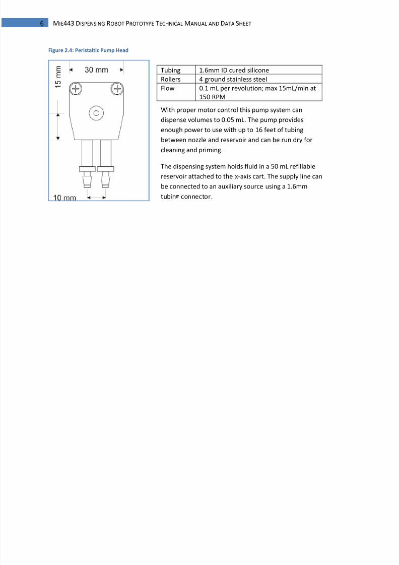
Figure 2.4: Peristaltic Pump Head
Tubing 1.6mm ID cured silicone
Rollers 4 ground stainless steel
Flow 0.1 mL per revolution; max 15mL/min at
150 RPMWith proper motor control this pump system can
dispense volumes to 0.05 mL. The pump provides
enough power to use with up to 16 feet of tubing
between nozzle and reservoir and can be run dry for
cleaning and priming.
The dispensing system holds fluid in a 50 mL refillable
reservoir attached to the x-axis cart. The supply line can
be connected to an auxiliary source using a 1.6mm
tubin connector.
8/7/2019 controle motor de passo microcontrolador
http://slidepdf.com/reader/full/controle-motor-de-passo-microcontrolador 8/28
7 MIE443 DISPENSING ROBOT PROTOTYPE TECHNICAL MANUAL AND DATA SHEET
3| ELECTRICAL SPECIFICATIONS
3.1 ELECTRICAL COMPONENTS
The following parts compose the electrical system of the dispenser:
PIC16F887 8-bit microcontroller; mounted on ETT BASE PIC 40 controller board
(3) Stepper motor controller printed circuit boards
(2) Lin Engineering 5718M-05S-05 1.8° High-Torque Step Motor
Howard Industries 1-19-4202 3.6° Step Motor
Tamiya RC-260 DC motor
DC (pump) motor control circuit
(3) Photointerupter Sensors
Photointerrupter buffer circuit
450W ATX PC power supply
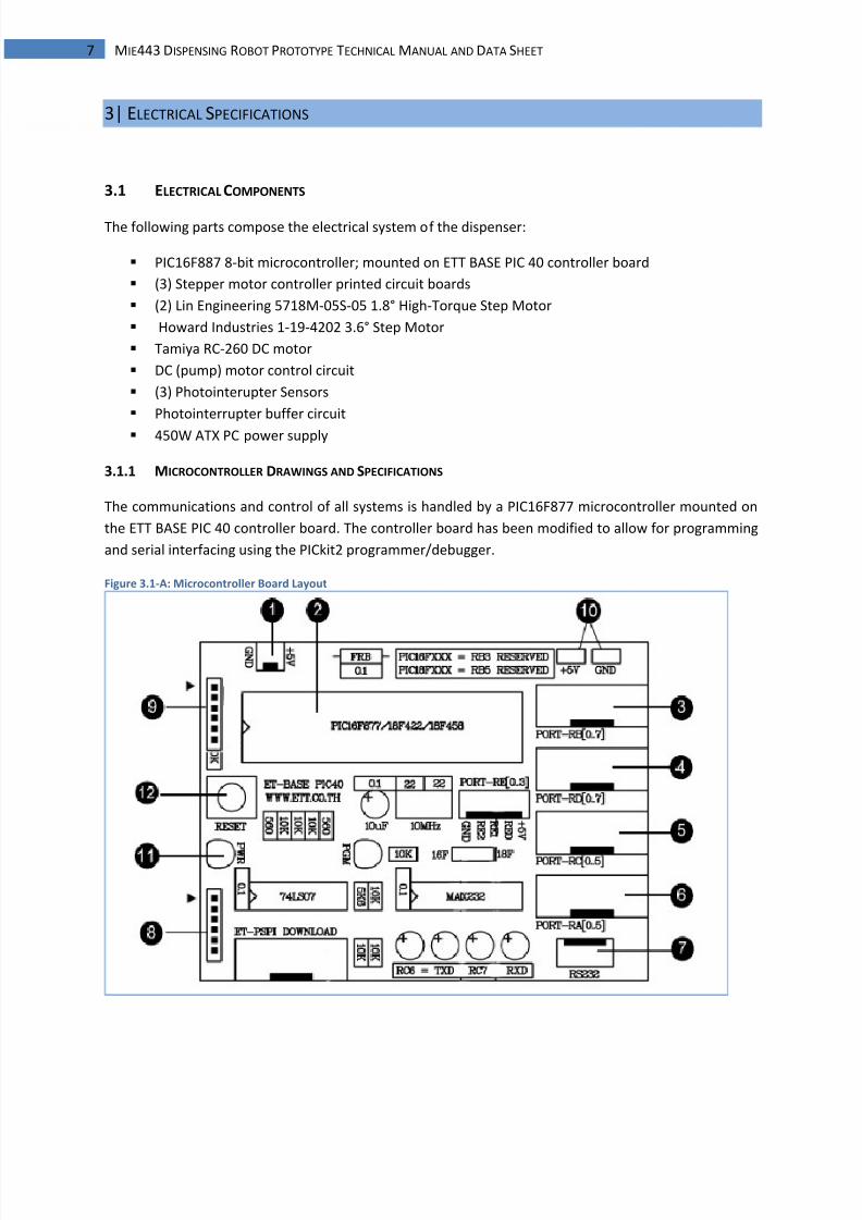
3.1.1 MICROCONTROLLER DRAWINGS AND SPECIFICATIONS
The communications and control of all systems is handled by a PIC16F877 microcontroller mounted on
the ETT BASE PIC 40 controller board. The controller board has been modified to allow for programming
and serial interfacing using the PICkit2 programmer/debugger.
Figure 3.1-A: Microcontroller Board Layout
8/7/2019 controle motor de passo microcontrolador
http://slidepdf.com/reader/full/controle-motor-de-passo-microcontrolador 9/28
8 MIE443 DISPENSING ROBOT PROTOTYPE TECHNICAL MANUAL AND DATA SHEET
CONTROLLER BOARD LAYOUT DESCRIPTION
1 Power connection. Mini-Molex from Power supply
(5V red; GND black)
2 PIC16F877 Microcontroller, 40 pin DIP
3 RB Signal Port I/O
4 RD Signal Port I/O5 RC Signal Port I/O
6 RA Signal Port I/O
7 RS-232 Serial communication port (not used)
8 PICkit2 programming port*
9 PICkit2 UART port*
10 5VDC supply and GND reference
11 Power LED
12 Reset push button
*See figure on right for proper connection of PICkit2 programmer
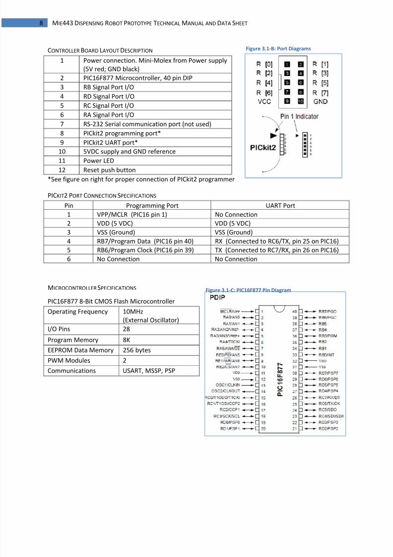
PICKIT2 PORT CONNECTION SPECIFICATIONS Pin Programming Port UART Port
1 VPP/MCLR (PIC16 pin 1) No Connection
2 VDD (5 VDC) VDD (5 VDC)
3 VSS (Ground) VSS (Ground)
4 RB7/Program Data (PIC16 pin 40) RX (Connected to RC6/TX, pin 25 on PIC16)
5 RB6/Program Clock (PIC16 pin 39) TX (Connected to RC7/RX, pin 26 on PIC16)
6 No Connection No Connection
MICROCONTROLLER SPECIFICATIONS
PIC16F877 8-Bit CMOS Flash Microcontroller
Operating Frequency 10MHz
(External Oscillator)
I/O Pins 28
Program Memory 8K
EEPROM Data Memory 256 bytes
PWM Modules 2
Communications USART, MSSP, PSP
Figure 3.1-B: Port Diagrams
Figure 3.1-C: PIC16F877 Pin Diagram
8/7/2019 controle motor de passo microcontrolador
http://slidepdf.com/reader/full/controle-motor-de-passo-microcontrolador 10/28
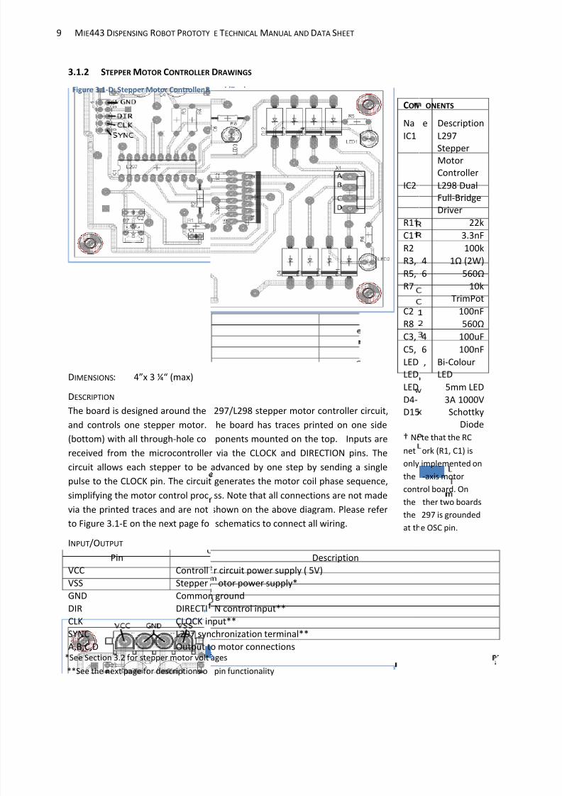
9 MIE443 DISPENSING ROBOT PROTOTY
3.1.2 STEPPER MOTOR CONTROLLER
DIMENSIONS: 4”x 3 ¼“ (max)
DESCRIPTION
The board is designed around the
and controls one stepper motor.
(bottom) with all through-hole co
received from the microcontroller
circuit allows each stepper to be
pulse to the CLOCK pin. The circuit
simplifying the motor control proc
via the printed traces and are not
to Figure 3.1-E on the next page fo
INPUT/OUTPUT
PinVCC Controll
VSS Stepper
GND Common
DIR DIRECTI
CLK CLOCK in
SYNC L297 syn
A,B,C,D Output t
Figure 3.1-D: Stepper Motor Controller B
*See Section 3.2 for stepper motor volt
**See the next page for descriptions o
E TECHNICAL MANUAL AND DATA SHEET
COM
Na
IC1
IC2
R1†
C1†
R2
R3,
R5,
R7
C2
R8
C3,
C5,
LED
LED
LED
D4-
D15
† No
net
only
the
cont
the
the
at th
DRAWINGS
297/L298 stepper motor controller circuit,
he board has traces printed on one side
ponents mounted on the top. Inputs are
via the CLOCK and DIRECTION pins. The
advanced by one step by sending a single
generates the motor coil phase sequence,
ss. Note that all connections are not made
shown on the above diagram. Please refer
schematics to connect all wiring.
Descriptionr circuit power supply ( 5V)
otor power supply*
ground
N control input**
put**
chronization terminal**
o motor connections
ard (Top)
ages
pin functionality
PONENTS
e Description
L297Stepper
Motor
Controller
L298 Dual
Full-Bridge
Driver
22k
3.3nF
100k
4 1Ω (2W)
6 560Ω
10k
TrimPot
100nF
560Ω
4 100uF
6 100nF
, Bi-Colour
LED
5mm LED
3A 1000V
Schottky
Diode
te that the RC
ork (R1, C1) is
implemented on
-axis motor
rol board. On
ther two boards
297 is grounded
e OSC pin.
8/7/2019 controle motor de passo microcontrolador
http://slidepdf.com/reader/full/controle-motor-de-passo-microcontrolador 11/28
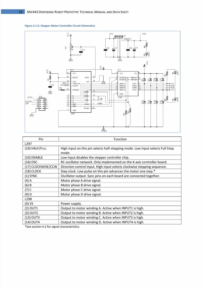
10 MIE443 DISPENSING ROBOT PROTOTYPE TECHNICAL MANUAL AND DATA SHEET
Figure 3.1-E: Stepper Motor Controller Circuit Schematics
Pin Function
L297
(19) HALF/FULL High input on this pin selects half-stepping mode. Low input selects Full Step
mode.(10) ENABLE Low input disables the stepper controller chip.
(16) OSC RC oscillator network. Only implemented on the X-axis controller board.
(17) CLOCKWISE/CCW Direction control input. High input selects clockwise stepping sequence.
(18) CLOCK Step clock. Low pulse on this pin advances the motor one step.*
(1) SYNC Oscillator output. Sync pins on each board are connected together.
(4) A Motor phase A drive signal.
(6) B Motor phase B drive signal.
(7) C Motor phase C drive signal.
(9) D Motor phase D drive signal.
L298
(4) VS Power supply.(2) OUT1 Output to motor winding A. Active when INPUT1 is high.
(3) OUT2 Output to motor winding B. Active when INPUT2 is high.
(13) OUT3 Output to motor winding C. Active when INPUT3 is high.
(14) OUT4 Output to motor winding D. Active when INPUT4 is high.
*See section 4.2 for signal characteristics
8/7/2019 controle motor de passo microcontrolador
http://slidepdf.com/reader/full/controle-motor-de-passo-microcontrolador 12/28
11 MIE443 DISPENSING ROBOT PROTOTYPE TECHNICAL MANUAL AND DATA SHEET
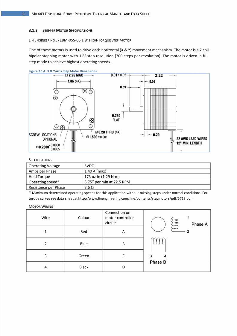
3.1.3 STEPPER MOTOR SPECIFICATIONS
LIN ENGINEERING 5718M-05S-05 1.8° HIGH-TORQUE STEP MOTOR
One of these motors is used to drive each horizontal (X & Y) movement mechanism. The motor is a 2 coil
bipolar stepping motor with 1.8° step resolution (200 steps per revolution). The motor is driven in full
step mode to achieve highest operating speeds.
Figure 3.1-F: X & Y-Axis Step Motor Dimensions
SPECIFICATIONS
Operating Voltage 5VDC
Amps per Phase 1.40 A (max)
Hold Torque 173 oz-in (1.29 N-m)Operating speed* 3.75“ per min at 22.5 RPM
Resistance per Phase 3.6 Ω
* Maximum determined operating speeds for this application without missing steps under normal conditions. For
torque curves see data sheet at http://www.linengineering.com/line/contents/stepmotors/pdf/5718.pdf
MOTOR WIRING
Wire Colour
Connection on
motor controller
circuit
1 Red A
2 Blue B
3 Green C
4 Black D
8/7/2019 controle motor de passo microcontrolador
http://slidepdf.com/reader/full/controle-motor-de-passo-microcontrolador 13/28
12 MIE443 DISPENSING ROBOT PROTOTYPE TECHNICAL MANUAL AND DATA SHEET
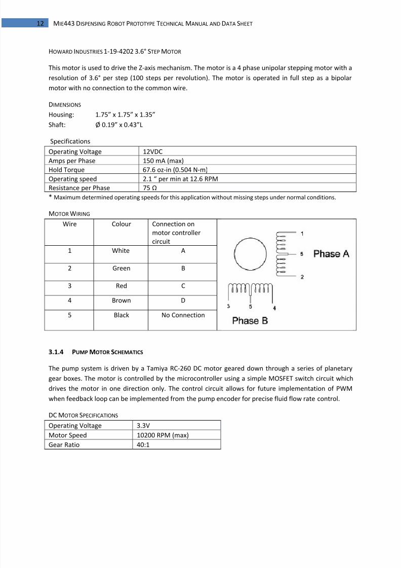
HOWARD INDUSTRIES 1-19-4202 3.6° STEP MOTOR
This motor is used to drive the Z-axis mechanism. The motor is a 4 phase unipolar stepping motor with a
resolution of 3.6° per step (100 steps per revolution). The motor is operated in full step as a bipolar
motor with no connection to the common wire.
DIMENSIONS
Housing: 1.75” x 1.75” x 1.35”
Shaft: Ø 0.19” x 0.43”L
Specifications
Operating Voltage 12VDC
Amps per Phase 150 mA (max)
Hold Torque 67.6 oz-in (0.504 N-m)
Operating speed 2.1 “ per min at 12.6 RPM
Resistance per Phase 75 Ω
* Maximum determined operating speeds for this application without missing steps under normal conditions.
MOTOR WIRING
Wire Colour Connection on
motor controller
circuit
1 White A
2 Green B
3 Red C
4 Brown D
5 Black No Connection
3.1.4 PUMP MOTOR SCHEMATICS
The pump system is driven by a Tamiya RC-260 DC motor geared down through a series of planetary
gear boxes. The motor is controlled by the microcontroller using a simple MOSFET switch circuit which
drives the motor in one direction only. The control circuit allows for future implementation of PWM
when feedback loop can be implemented from the pump encoder for precise fluid flow rate control.
DC MOTOR SPECIFICATIONS
Operating Voltage 3.3V
Motor Speed 10200 RPM (max)
Gear Ratio 40:1
8/7/2019 controle motor de passo microcontrolador
http://slidepdf.com/reader/full/controle-motor-de-passo-microcontrolador 14/28
13 MIE443 DISPENSING ROBOT PROTOTYPE TECHNICAL MANUAL AND DATA SHEET
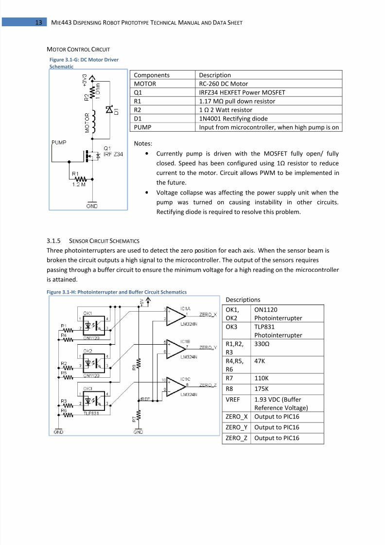
MOTOR CONTROL CIRCUIT
Components Description
MOTOR RC-260 DC Motor
Q1 IRFZ34 HEXFET Power MOSFETR1 1.17 MΩ pull down resistor
R2 1 Ω 2 Watt resistor
D1 1N4001 Rectifying diode
PUMP Input from microcontroller, when high pump is on
Notes:
• Currently pump is driven with the MOSFET fully open/ fully
closed. Speed has been configured using 1Ω resistor to reduce
current to the motor. Circuit allows PWM to be implemented in
the future.
• Voltage collapse was affecting the power supply unit when the
pump was turned on causing instability in other circuits.
Rectifying diode is required to resolve this problem.
3.1.5 SENSOR CIRCUIT SCHEMATICS
Three photointerrupters are used to detect the zero position for each axis. When the sensor beam is
broken the circuit outputs a high signal to the microcontroller. The output of the sensors requires
passing through a buffer circuit to ensure the minimum voltage for a high reading on the microcontroller
is attained.
Figure 3.1-H: Photointerrupter and Buffer Circuit Schematics
Descriptions
OK1,
OK2
ON1120
Photointerrupter
OK3 TLP831
Photointerrupter
R1,R2,
R3
330Ω
R4,R5,
R6
47K
R7 110K
R8 175K
VREF 1.93 VDC (Buffer
Reference Voltage)
ZERO_X Output to PIC16
ZERO_Y Output to PIC16
ZERO_Z Output to PIC16
Figure 3.1-G: DC Motor Driver
Schematic
8/7/2019 controle motor de passo microcontrolador
http://slidepdf.com/reader/full/controle-motor-de-passo-microcontrolador 15/28
14 MIE443 DISPENSING ROBOT PROTOTYPE TECHNICAL MANUAL AND DATA SHEET
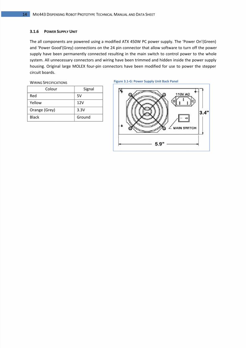
3.1.6 POWER SUPPLY UNIT
The all components are powered using a modified ATX 450W PC power supply. The ‘Power On’(Green)
and ‘Power Good’(Grey) connections on the 24 pin connector that allow software to turn off the power
supply have been permanently connected resulting in the main switch to control power to the whole
system. All unnecessary connectors and wiring have been trimmed and hidden inside the power supplyhousing. Original large MOLEX four-pin connectors have been modified for use to power the stepper
circuit boards.
WIRING SPECIFICATIONS
Colour Signal
Red 5V
Yellow 12V
Orange (Grey) 3.3V
Black Ground
Figure 3.1-G: Power Supply Unit Back Panel
8/7/2019 controle motor de passo microcontrolador
http://slidepdf.com/reader/full/controle-motor-de-passo-microcontrolador 16/28
15 MIE443 DISPENSING ROBOT PROTOTYPE TECHNICAL MANUAL AND DATA SHEET
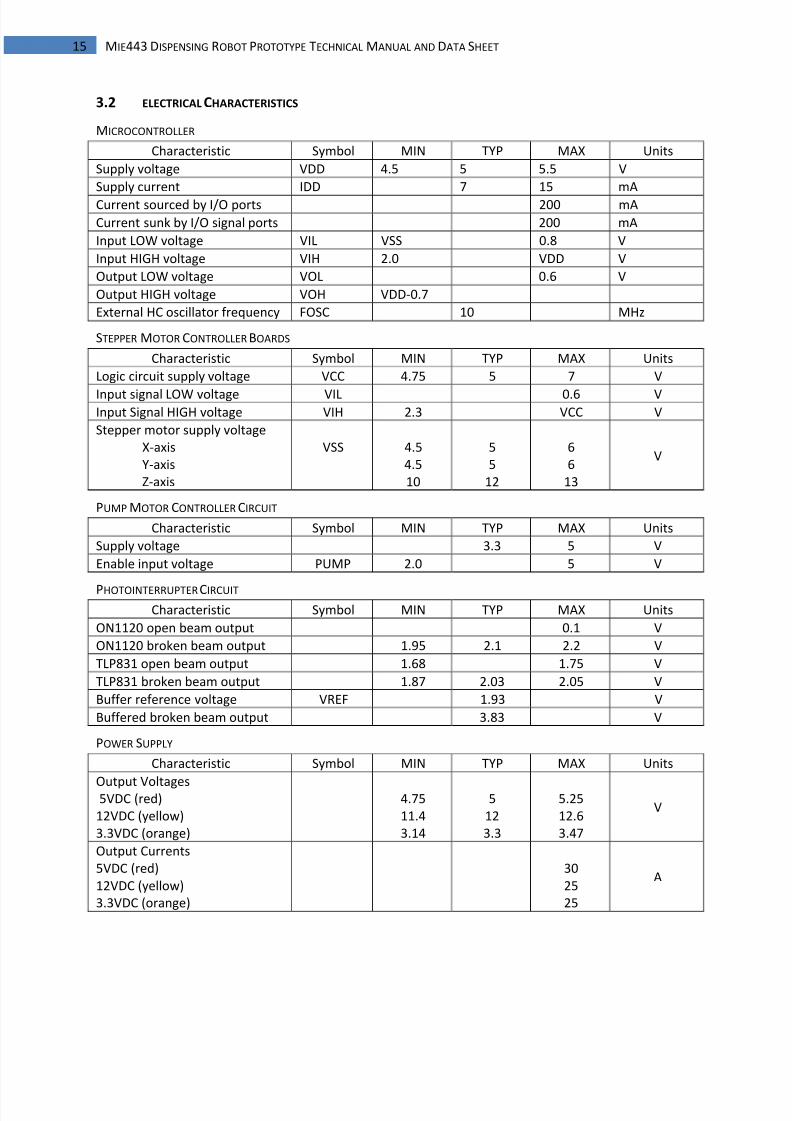
3.2 ELECTRICAL CHARACTERISTICS
MICROCONTROLLER
Characteristic Symbol MIN TYP MAX Units
Supply voltage VDD 4.5 5 5.5 V
Supply current IDD 7 15 mA
Current sourced by I/O ports 200 mA
Current sunk by I/O signal ports 200 mA
Input LOW voltage VIL VSS 0.8 V
Input HIGH voltage VIH 2.0 VDD V
Output LOW voltage VOL 0.6 V
Output HIGH voltage VOH VDD-0.7
External HC oscillator frequency FOSC 10 MHz
STEPPER MOTOR CONTROLLER BOARDS
Characteristic Symbol MIN TYP MAX Units
Logic circuit supply voltage VCC 4.75 5 7 V
Input signal LOW voltage VIL 0.6 VInput Signal HIGH voltage VIH 2.3 VCC V
Stepper motor supply voltage
X-axis
Y-axis
Z-axis
VSS 4.5
4.5
10
5
5
12
6
6
13
V
PUMP MOTOR CONTROLLER CIRCUIT
Characteristic Symbol MIN TYP MAX Units
Supply voltage 3.3 5 V
Enable input voltage PUMP 2.0 5 V
PHOTOINTERRUPTER CIRCUIT Characteristic Symbol MIN TYP MAX Units
ON1120 open beam output 0.1 V
ON1120 broken beam output 1.95 2.1 2.2 V
TLP831 open beam output 1.68 1.75 V
TLP831 broken beam output 1.87 2.03 2.05 V
Buffer reference voltage VREF 1.93 V
Buffered broken beam output 3.83 V
POWER SUPPLY
Characteristic Symbol MIN TYP MAX Units
Output Voltages5VDC (red)
12VDC (yellow)
3.3VDC (orange)
4.75
11.4
3.14
5
12
3.3
5.25
12.6
3.47
V
Output Currents
5VDC (red)
12VDC (yellow)
3.3VDC (orange)
30
25
25
A
8/7/2019 controle motor de passo microcontrolador
http://slidepdf.com/reader/full/controle-motor-de-passo-microcontrolador 17/28
16 MIE443 DISPENSING ROBOT PROTOTYPE TECHNICAL MANUAL AND DATA SHEET
4| CONTROL SYSTEM
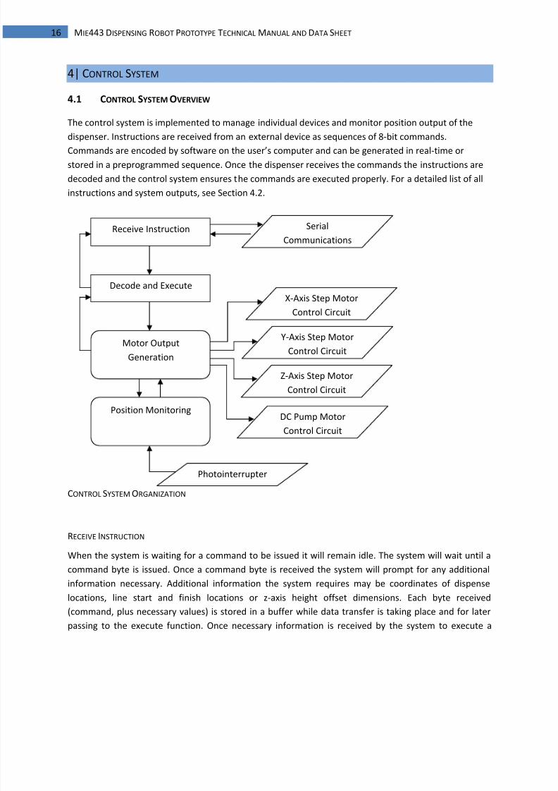
4.1 CONTROL SYSTEM OVERVIEW
The control system is implemented to manage individual devices and monitor position output of the
dispenser. Instructions are received from an external device as sequences of 8-bit commands.Commands are encoded by software on the user’s computer and can be generated in real-time or
stored in a preprogrammed sequence. Once the dispenser receives the commands the instructions are
decoded and the control system ensures the commands are executed properly. For a detailed list of all
instructions and system outputs, see Section 4.2.
CONTROL SYSTEM ORGANIZATION
RECEIVE INSTRUCTION
When the system is waiting for a command to be issued it will remain idle. The system will wait until acommand byte is issued. Once a command byte is received the system will prompt for any additional
information necessary. Additional information the system requires may be coordinates of dispense
locations, line start and finish locations or z-axis height offset dimensions. Each byte received
(command, plus necessary values) is stored in a buffer while data transfer is taking place and for later
passing to the execute function. Once necessary information is received by the system to execute a
Z-Axis Step Motor
Control Circuit
Position Monitoring
Receive Instruction
Decode and Execute
Serial
Communications
Motor Output
Generation
X-Axis Step Motor
Control Circuit
Y-Axis Step Motor
Control Circuit
DC Pump MotorControl Circuit
Photointerrupter
8/7/2019 controle motor de passo microcontrolador
http://slidepdf.com/reader/full/controle-motor-de-passo-microcontrolador 18/28
17 MIE443 DISPENSING ROBOT PROTOTYPE TECHNICAL MANUAL AND DATA SHEET
command, the system closes the communications and any data transferred will result in a
misinterpreted command when the communications are initialized to receive the next command.
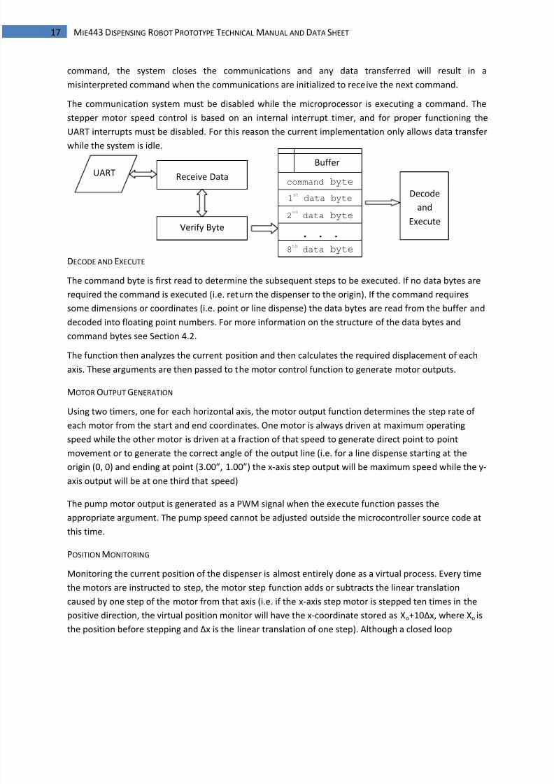
The communication system must be disabled while the microprocessor is executing a command. The
stepper motor speed control is based on an internal interrupt timer, and for proper functioning the
UART interrupts must be disabled. For this reason the current implementation only allows data transfer
while the system is idle.
DECODE AND EXECUTE
The command byte is first read to determine the subsequent steps to be executed. If no data bytes are
required the command is executed (i.e. return the dispenser to the origin). If the command requires
some dimensions or coordinates (i.e. point or line dispense) the data bytes are read from the buffer and
decoded into floating point numbers. For more information on the structure of the data bytes and
command bytes see Section 4.2.
The function then analyzes the current position and then calculates the required displacement of each
axis. These arguments are then passed to the motor control function to generate motor outputs.
MOTOR OUTPUT GENERATION
Using two timers, one for each horizontal axis, the motor output function determines the step rate of each motor from the start and end coordinates. One motor is always driven at maximum operating
speed while the other motor is driven at a fraction of that speed to generate direct point to point
movement or to generate the correct angle of the output line (i.e. for a line dispense starting at the
origin (0, 0) and ending at point (3.00”, 1.00”) the x-axis step output will be maximum speed while the y-
axis output will be at one third that speed)
The pump motor output is generated as a PWM signal when the execute function passes the
appropriate argument. The pump speed cannot be adjusted outside the microcontroller source code at
this time.
POSITION MONITORING
Monitoring the current position of the dispenser is almost entirely done as a virtual process. Every time
the motors are instructed to step, the motor step function adds or subtracts the linear translation
caused by one step of the motor from that axis (i.e. if the x-axis step motor is stepped ten times in the
positive direction, the virtual position monitor will have the x-coordinate stored as Xo+10Δx, where Xo is
the position before stepping and Δx is the linear translation of one step). Although a closed loop
Receive Datacommand byte
1st
data byte
2nd
data byte
. . .
8th
data byte
Decode
and
Execute
UARTBuffer
Verify Byte
8/7/2019 controle motor de passo microcontrolador
http://slidepdf.com/reader/full/controle-motor-de-passo-microcontrolador 19/28
18 MIE443 DISPENSING ROBOT PROTOTYPE TECHNICAL MANUAL AND DATA SHEET
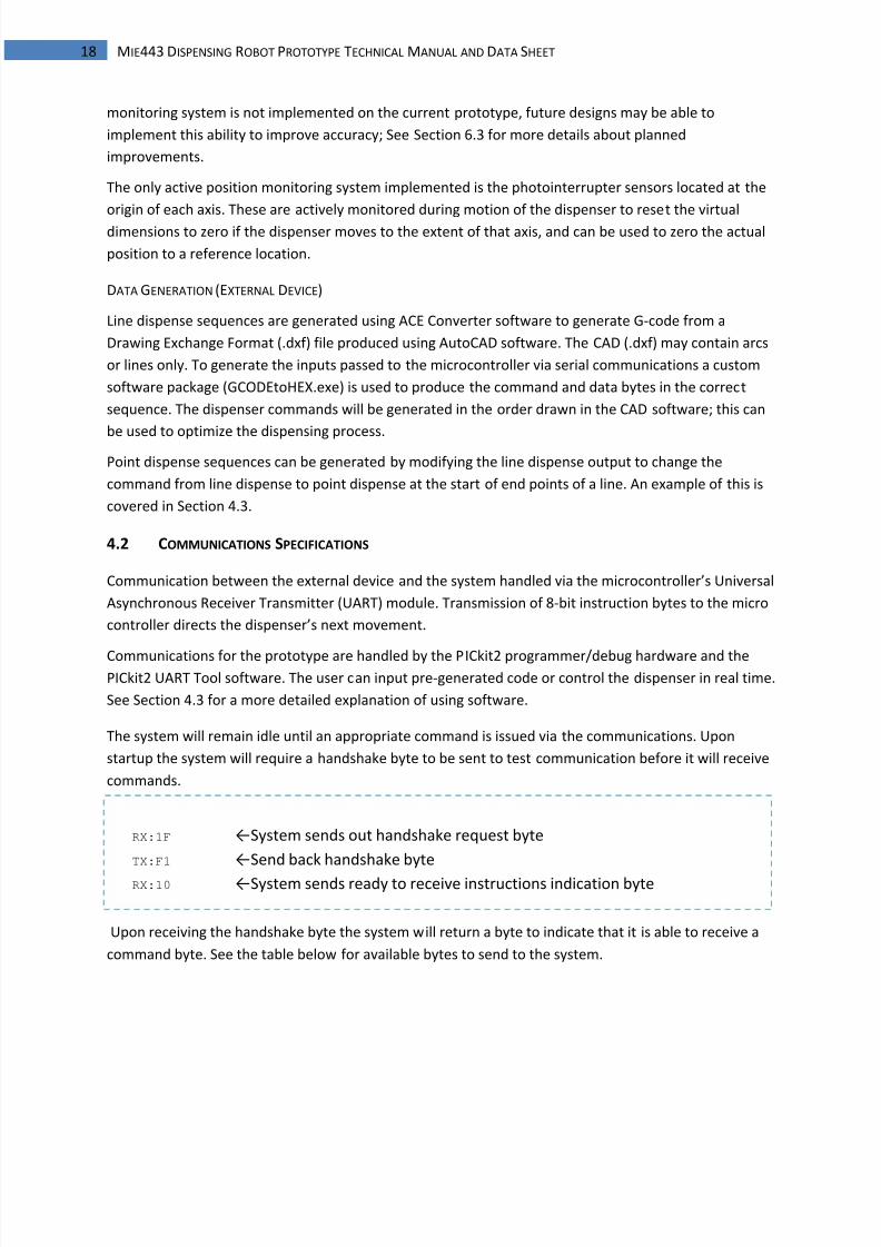
RX:1F ←System sends out handshake request byte
TX:F1 ←Send back handshake byte
RX:10 ←System sends ready to receive instructions indication byte
monitoring system is not implemented on the current prototype, future designs may be able to
implement this ability to improve accuracy; See Section 6.3 for more details about planned
improvements.
The only active position monitoring system implemented is the photointerrupter sensors located at the
origin of each axis. These are actively monitored during motion of the dispenser to reset the virtual
dimensions to zero if the dispenser moves to the extent of that axis, and can be used to zero the actual
position to a reference location.
DATA GENERATION (EXTERNAL DEVICE)
Line dispense sequences are generated using ACE Converter software to generate G-code from a
Drawing Exchange Format (.dxf) file produced using AutoCAD software. The CAD (.dxf) may contain arcs
or lines only. To generate the inputs passed to the microcontroller via serial communications a custom
software package (GCODEtoHEX.exe) is used to produce the command and data bytes in the correct
sequence. The dispenser commands will be generated in the order drawn in the CAD software; this can
be used to optimize the dispensing process.Point dispense sequences can be generated by modifying the line dispense output to change the
command from line dispense to point dispense at the start of end points of a line. An example of this is
covered in Section 4.3.
4.2 COMMUNICATIONS SPECIFICATIONS
Communication between the external device and the system handled via the microcontroller’s Universal
Asynchronous Receiver Transmitter (UART) module. Transmission of 8-bit instruction bytes to the micro
controller directs the dispenser’s next movement.
Communications for the prototype are handled by the PICkit2 programmer/debug hardware and thePICkit2 UART Tool software. The user can input pre-generated code or control the dispenser in real time.
See Section 4.3 for a more detailed explanation of using software.
The system will remain idle until an appropriate command is issued via the communications. Upon
startup the system will require a handshake byte to be sent to test communication before it will receive
commands.
Upon receiving the handshake byte the system will return a byte to indicate that it is able to receive a
command byte. See the table below for available bytes to send to the system.
8/7/2019 controle motor de passo microcontrolador
http://slidepdf.com/reader/full/controle-motor-de-passo-microcontrolador 20/28
19 MIE443 DISPENSING ROBOT PROTOTYPE TECHNICAL MANUAL AND DATA SHEET
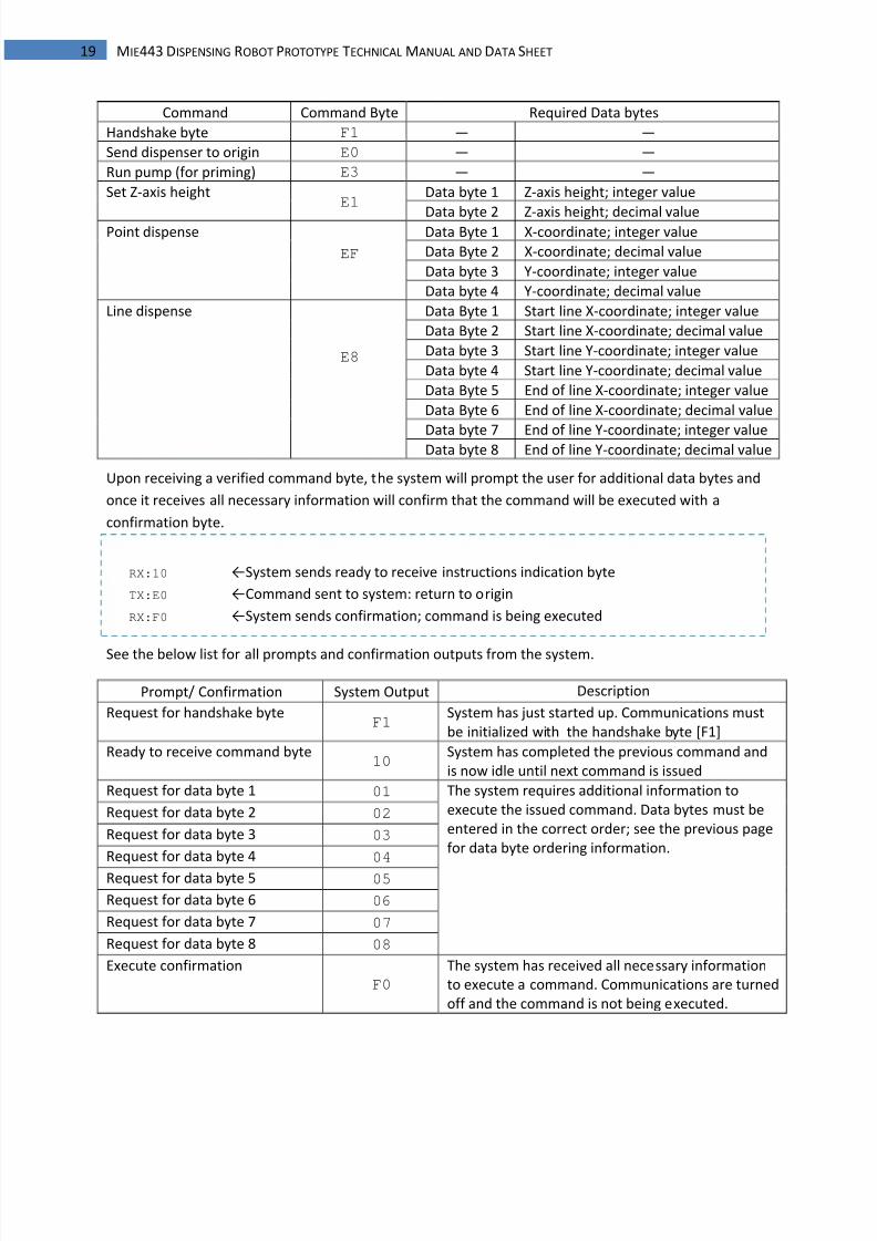
RX:10 ←System sends ready to receive instructions indication byte
TX:E0 ←Command sent to system: return to origin
RX:F0 ←System sends confirmation; command is being executed
Command Command Byte Required Data bytes
Handshake byte F1 ― ―
Send dispenser to origin E0 ― ―
Run pump (for priming) E3 ― ―
Set Z-axis heightE1
Data byte 1 Z-axis height; integer value
Data byte 2 Z-axis height; decimal valuePoint dispense
EF
Data Byte 1 X-coordinate; integer value
Data Byte 2 X-coordinate; decimal value
Data byte 3 Y-coordinate; integer value
Data byte 4 Y-coordinate; decimal value
Line dispense
E8
Data Byte 1 Start line X-coordinate; integer value
Data Byte 2 Start line X-coordinate; decimal value
Data byte 3 Start line Y-coordinate; integer value
Data byte 4 Start line Y-coordinate; decimal value
Data Byte 5 End of line X-coordinate; integer value
Data Byte 6 End of line X-coordinate; decimal value
Data byte 7 End of line Y-coordinate; integer valueData byte 8 End of line Y-coordinate; decimal value
Upon receiving a verified command byte, the system will prompt the user for additional data bytes and
once it receives all necessary information will confirm that the command will be executed with a
confirmation byte.
See the below list for all prompts and confirmation outputs from the system.
Prompt/ Confirmation System Output Description
Request for handshake byteF1
System has just started up. Communications must
be initialized with the handshake byte [F1]
Ready to receive command byte10
System has completed the previous command and
is now idle until next command is issued
Request for data byte 1 01 The system requires additional information to
execute the issued command. Data bytes must be
entered in the correct order; see the previous page
for data byte ordering information.
Request for data byte 2 02
Request for data byte 3 03
Request for data byte 4 04
Request for data byte 5 05
Request for data byte 6 06
Request for data byte 7 07
Request for data byte 8 08
Execute confirmation
F0
The system has received all necessary information
to execute a command. Communications are turned
off and the command is not being executed.
8/7/2019 controle motor de passo microcontrolador
http://slidepdf.com/reader/full/controle-motor-de-passo-microcontrolador 21/28
20 MIE443 DISPENSING ROBOT PROTOTYPE TECHNICAL MANUAL AND DATA SHEET
No communication can be sent while the system is executing a command. Ensure that the system
prompts for a command before transmitting any bytes.
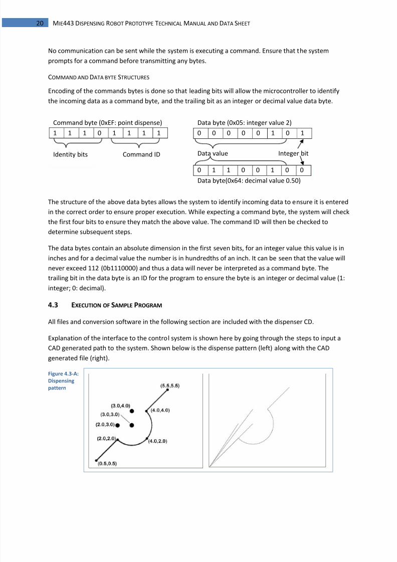
COMMAND AND DATA BYTE STRUCTURES
Encoding of the commands bytes is done so that leading bits will allow the microcontroller to identify
the incoming data as a command byte, and the trailing bit as an integer or decimal value data byte.
The structure of the above data bytes allows the system to identify incoming data to ensure it is entered
in the correct order to ensure proper execution. While expecting a command byte, the system will check
the first four bits to ensure they match the above value. The command ID will then be checked to
determine subsequent steps.
The data bytes contain an absolute dimension in the first seven bits, for an integer value this value is in
inches and for a decimal value the number is in hundredths of an inch. It can be seen that the value will
never exceed 112 (0b1110000) and thus a data will never be interpreted as a command byte. The
trailing bit in the data byte is an ID for the program to ensure the byte is an integer or decimal value (1:
integer; 0: decimal).
4.3 EXECUTION OF SAMPLE PROGRAM
All files and conversion software in the following section are included with the dispenser CD.
Explanation of the interface to the control system is shown here by going through the steps to input a
CAD generated path to the system. Shown below is the dispense pattern (left) along with the CAD
generated file (right).
Figure 4.3-A:
Dispensing
pattern
Command byte (0xEF: point dispense)
1 1 1 0 1 1 1 1
Identity bits Command ID
Data byte (0x05: integer value 2)
0 0 0 0 0 1 0 1
Data value Integer bit
0 1 1 0 0 1 0 0
Data byte(0x64: decimal value 0.50)
8/7/2019 controle motor de passo microcontrolador
http://slidepdf.com/reader/full/controle-motor-de-passo-microcontrolador 22/28
21 MIE443 DISPENSING ROBOT PROTOTYPE TECHNICAL MANUAL AND DATA SHEET
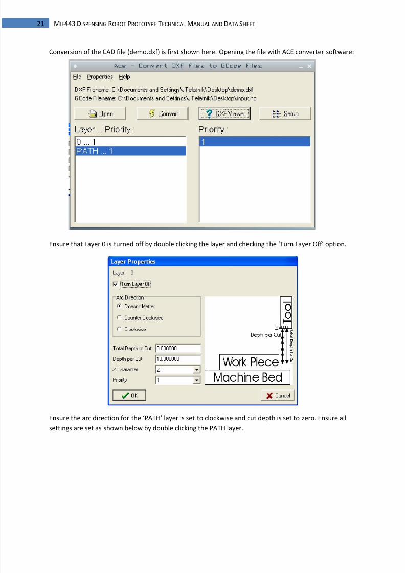
Conversion of the CAD file (demo.dxf) is first shown here. Opening the file with ACE converter software:
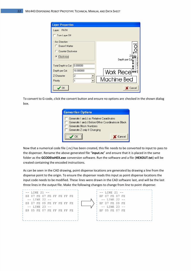
Ensure that Layer 0 is turned off by double clicking the layer and checking the ‘Turn Layer Off’ option.
Ensure the arc direction for the ‘PATH’ layer is set to clockwise and cut depth is set to zero. Ensure all
settings are set as shown below by double clicking the PATH layer.
8/7/2019 controle motor de passo microcontrolador
http://slidepdf.com/reader/full/controle-motor-de-passo-microcontrolador 23/28
22 MIE443 DISPENSING ROBOT PROTOTYPE TECHNICAL MANUAL AND DATA SHEET
To convert to G-code, click the convert button and ensure no options are checked in the shown dialog
box.
Now that a numerical code file (.nc) has been created, this file needs to be converted to input to pass to
the dispenser. Rename the above generated file “input.nc” and ensure that it is placed in the same
folder as the GCODEtoHEX.exe conversion software. Run the software and a file (HEXOUT.txt) will be
created containing the encoded instructions.
As can be seen in the CAD drawing, point dispense locations are generated by drawing a line from the
dispense point to the origin. To ensure the dispenser reads this input as point dispense locations the
input code needs to be modified. These lines were drawn in the CAD software last, and will be the last
three lines in the output file. Make the following changes to change from line to point dispense:
-- LINE 21 --
E8 07 FE 07 FE FF FE FF FE
-- LINE 22 --
E8 07 FE 09 FE FF FE FF FE
-- LINE 23 --
E8 05 FE 07 FE FF FE FF FE
-- LINE 21 --
EF 07 FE 07 FE
-- LINE 22 --
EF 07 FE 09 FE
-- LINE 23 --
EF 05 FE 07 FE
8/7/2019 controle motor de passo microcontrolador
http://slidepdf.com/reader/full/controle-motor-de-passo-microcontrolador 24/28
23 MIE443 DISPENSING ROBOT PROTOTYPE TECHNICAL MANUAL AND DATA SHEET
The above modification changes the command byte from line dispense to point dispense and strips the
unnecessary data bytes (end of line coordinates). See section 4.2 for command and data byte
references.
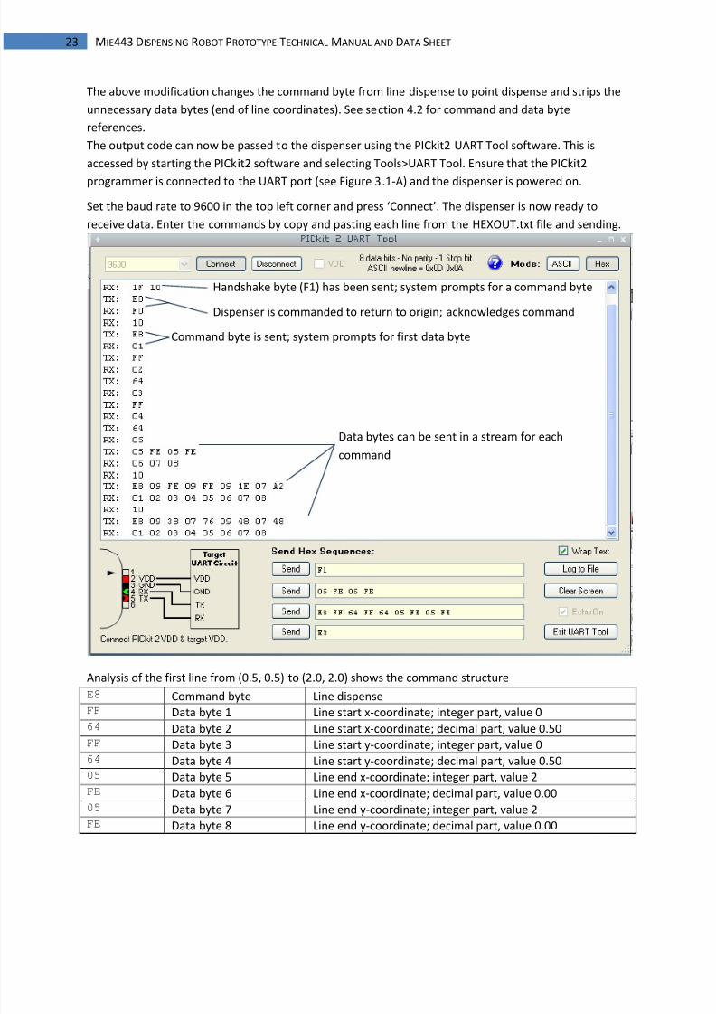
The output code can now be passed to the dispenser using the PICkit2 UART Tool software. This is
accessed by starting the PICkit2 software and selecting Tools>UART Tool. Ensure that the PICkit2
programmer is connected to the UART port (see Figure 3.1-A) and the dispenser is powered on.
Set the baud rate to 9600 in the top left corner and press ‘Connect’. The dispenser is now ready to
receive data. Enter the commands by copy and pasting each line from the HEXOUT.txt file and sending.
Analysis of the first line from (0.5, 0.5) to (2.0, 2.0) shows the command structure
E8 Command byte Line dispense
FF Data byte 1 Line start x-coordinate; integer part, value 064 Data byte 2 Line start x-coordinate; decimal part, value 0.50FF Data byte 3 Line start y-coordinate; integer part, value 064 Data byte 4 Line start y-coordinate; decimal part, value 0.5005 Data byte 5 Line end x-coordinate; integer part, value 2FE Data byte 6 Line end x-coordinate; decimal part, value 0.0005 Data byte 7 Line end y-coordinate; integer part, value 2FE Data byte 8 Line end y-coordinate; decimal part, value 0.00
Handshake byte (F1) has been sent; system prompts for a command byte
Dispenser is commanded to return to origin; acknowledges command
Command byte is sent; system prompts for first data byte
Data bytes can be sent in a stream for each
command
8/7/2019 controle motor de passo microcontrolador
http://slidepdf.com/reader/full/controle-motor-de-passo-microcontrolador 25/28
24 MIE443 DISPENSING ROBOT PROTOTYPE TECHNICAL MANUAL AND DATA SHEET
5| PROTOTYPE TESTING AND FUNCTIONALITY
MECHANICAL STRUCTURE
The layout of the structure was found to meet its design goals, but new issues were found during
construction and testing. The overhead operating mechanism was successful in allowing for a stationary
work area that has no weight restrictions and allows for use with customized workbench fixtures. Use of
aluminum as a building material resulted in easy machining of the components, and proved a strong
enough to not introduce any concerns about failure of components.
As most of the components were custom fabricated from raw materials for this design, issues with such
as alignment of the movement mechanism and other issues rising from poor dimensioning of machined
components were common. Although mechanisms could still function with these inaccuracies in
dimensioning, additional resistance and some mechanical backlash was added to the movement
mechanism.
MOVEMENT MECHANISM
The lead screw translation system powered by stepper motors was able to be implemented with some
anticipated problems. When the mechanisms were disconnected from each other the lead screws on
the x and y axis where able to be driven at close to the intended top speed without failing to step;
however when connected together the rail-roller system made proved to be poorly designed and
misaligned. At certain sections the resistance from rolling friction and a bending force on the lead screw
caused the stepping motors to misstep and good accuracy could not be attained. After loosening the
system by using split washers for increased spacing between components, the system lost rigidity but
did not get stuck while moving. The shake in the system was determined to affect the accuracy of the
output, line dispense paths can show the position error problems as the dispenser nozzle can be seen to
deviate from its straight line path. Alignment issues in the vertical axis mechanism reduced the actual
vertical displacement of the cart to 1.25”. This problem could not be solved.
The lead screw mechanism proved to be mechanically accurate. The system was able to be used to
provide accurate dimensional output from calculations established in the design stage of the system. No
compensation for inaccuracies was required in the software. The system did show weaknesses in
repeatability, a maximum of 0.22” deviation from the intended position after 37” of movement was
measured. Based on usability of this prototype, the dimensions of the work area can be easily modified
to larger sizes by simply extending the size of the lead screw and railings to the desired length in the
subsequent design. The modularity of this design is a large success.
STEP MOTOR OPERATION
Control of the step motors through the L297 based control circuit proved successful. Motors where able
to be driven accurately with no calibration needed and no noticeable discrepancies between stepping
speeds and calculated output pulse frequency could be seen.
Issues occurred when motors were connected to the lead screws and the mechanism resistance was
larger than accounted for. The motors frequently missed steps and would not turn when faced with
8/7/2019 controle motor de passo microcontrolador
http://slidepdf.com/reader/full/controle-motor-de-passo-microcontrolador 26/28
25 MIE443 DISPENSING ROBOT PROTOTYPE TECHNICAL MANUAL AND DATA SHEET
some resistance. Based on the motor torque curves, motors were estimated to be able to run at 60
RPM; however the unaccounted additional mechanical resistance resulted in a reduction in speed to
22.5 RPM. Testing proved that at this speed the motors could be operated with confidence that the
motors would not misstep at significant frequencies. Hold torques on all motors were sufficient, while
powered on and stationary, the mechanism could not be moved by outside interference.
PUMPING SYSTEM
After evaluation of the pumping system, it has been concluded that the pump chosen may not be the
best method of fluid displacement. The advantages of the peristaltic mechanism, especially the
versatility in fluids able to be pumped, was noticed and appreciated immediately. The design of this type
of pump, however, provides pulsating fluid flow rate. This proved to not be a problem for point
dispensing, however dispensing of linear paths proved problematic. A pump encoder feedback, along
with PWM motor speed control was proposed to provide a more continuous pump motion, but this
system was not implemented on the current prototype.
MICROCONTROLLER
The 8-bit microcontroller was found to be the bare minimum to implement this sort of system. Limited
program and data memory limited the complexity of the system to merely a motor control system with
minimal feedback. Without expanded flash and program memory, the microcontroller unit (MCU) could
not execute more demanding calculations involving large floating point math and the accuracy of
received commands was kept to 0.01”. Implementation of advanced functionality, such as PID control of
positioning and advanced arc and spline path motions, require a more powerful MCU or two or more
MCUs in parallel to handle motor control and position monitoring simultaneously.
USER INTERFACE
A graphic user interface was under development that would handle all of the communication with the
machine, allowing a user to leave the machine running unsupervised. Communication issues with the
original hardware intended to be used resulted in switching to using the PICkit2 tool to handle
communications. With this hardware, the intended software could not be used and the user had to
enter command data manually.
Implementation of CAD programs for path design proved successful. Improvements need to be made to
allow a more intuitive conversion process.
8/7/2019 controle motor de passo microcontrolador
http://slidepdf.com/reader/full/controle-motor-de-passo-microcontrolador 27/28
26 MIE443 DISPENSING ROBOT PROTOTYPE TECHNICAL MANUAL AND DATA SHEET
6| FUTURE DEVELOPMENT
6.1 CHANGES TO MECHANICAL SYSTEM
To remove inaccuracies from machining custom components a simpler design is proposed. Although
more costly, a pre-manufactured precision bearing railing system or vice rail has been determined to benecessary to alleviate the mechanical instability that is limiting the current system.
Using railings will allow for an increase in speeds but for most fluid dispensing applications it has been
determined that the mechanical accuracy of the current systems is unnecessarily small and speed is
more important. This means step motors with a less accurate resolution but higher speeds and higher
torques can be used.
Although the pumping system proved inadequate for line dispensing on the current prototype, the
solution to this problems has been determined to be an improved control system on the pump motor
rather that switching to another dispensing system.
6.2 CHANGES TO ELECTRICAL SYSTEM
The current electronics proved to be very reliable and no significant changes are felt necessary. The
changes to be made are modification of the control circuitry into a package closer to the final product.
Circuit components can be included on one more compact circuit board. Use of advanced PCB
manufacturing technology will allow the use of more surface mount ICs and electronic components
which will reduce the size of the boards. A hardware change to a more permanent communication
system from the current PICkit2 tool is necessary for user convenience. A working UART to USB
connection will be implemented on the next model.
An important addition to the electrical system would be the addition of an optical encoder system to the
lead screws. This would allow precise monitoring of the real position of the cart and allow the system to
detect and fix any missed steps. These sensors would need an angular resolution at least as small as the
stepper resolution to detect missed steps.
6.3 CHANGES TO CONTROL SYSTEM
Testing revealed that possible replacements of the microcontroller unit (MCU) would be a more
powerful 16-bit micro controller or to split the necessary output and handling of data to two 8-bit MCUs
operating in parallel. Both systems would require external data memory to act as a communication
buffer for the two units. This would allow simultaneous communication and operation as well asposition control using external sensors and implementing PID control.
Implementation of sensors to detect rotation of the screws will allow real-time position monitoring and
provide data to compare to the virtual position. Motor speeds can be varied in real time to correct for
missed steps. This will allow for some allowance to run at higher speeds where missed steps are more
likely for mechanical reasons. These missed steps can then be corrected for used closed loop feedback.
8/7/2019 controle motor de passo microcontrolador
http://slidepdf.com/reader/full/controle-motor-de-passo-microcontrolador 28/28
27 MIE443 DISPENSING ROBOT PROTOTYPE TECHNICAL MANUAL AND DATA SHEET
This will improve the accuracy of the machine and allow the full resolution of the mechanical system to
be exploited.
An improved pump control system will likely need to be implemented to improve the accuracy of
volume dispensed. The peristaltic pump allows for this but an encoder feedback must be established to
allow for accurate dispensing of fluid, independent of fluid properties. The peristaltic pump dispenses acontestant volume per revolution, thus implementing PID control to accurately control the pump
revolutions will allow accurate dispensing and give possibility of feedback to the user of the volumes of
fluid being dispensed.
6.4 CHANGES TO PROGRAM INTERFACE
A visual user interface that allows the user to control the dispenser in real time or load and create pre-
programmed paths is under development that automates the communication and data conversion
process is under development. With additional development that will allow simultaneous motor control
and communication, the possibility of live feedback of the dispenser position to a graphic interface from
position feedback sensors exists. An easy to use user interface will allow more intuitive control of the
dispenser.