Cozinha Sob Pressão - Hell's Kitchen - Segunda Temporada - Volume 1
description

TECHNICAL EDUCATION
JOB AID 4317326A
KAR-11
2001 K MODEL
BUILT-IN SIDE-BY-SIDEREFRIGERATOR WITH VARIABLE
CAPACITY COMPRESSOR
MODELS:
KSSC36FKB00KSSC36FKS00KSSC36QKS00KSSC42FKB00KSSC42FKS00KSSC42QKS00KSSC48FKB00KSSC48FKS00KSSC48QKS00KSSP36QKS00KSSP42QKS00KSSP48QKS00KSSS36FKB00KSSS36FKT00KSSS36FKW00KSSS36FKX00KSSS36QKB00KSSS36QKT00KSSS36QKW00KSSS36QKX00
KSSS42FKB00KSSS42FKT00KSSS42FKW00KSSS42FKX00KSSS42QKB00KSSS42QKT00KSSS42QKW00KSSS42QKX00KSSS48FKB00KSSS48FKT00KSSS48FKW00KSSS48FKX00KSSS48QKB00KSSS48QKT00KSSS48QKW00KSSS48QKX00

- ii -
WHIRLPOOL CORPORATION assumes no responsibility for any repairs madeon our products by anyone other than Authorized Service Technicians.
FORWARDThis KitchenAid Job Aid, 2001 K Model Built-In Side-By-Side Refrigerator With Variable CapacityCompressor (Part No. 4317326A), provides the technician with information on the installation andservice of the Built-In Side-By-Side Refrigerator. It is to be used as a training Job Aid and ServiceManual. For specific information on the model being serviced, refer to the “Use and Care Guide,”or “Tech Sheet” provided with the refrigerator.
The Wiring Diagrams and Strip Circuits used in this Job Aid are typical and should be used fortraining purposes only. Always use the Wiring Diagram supplied with the product when servicingthe unit.
GOALS AND OBJECTIVESThe goal of this Job Aid is to provide detailed information that will enable the service technician toproperly diagnose malfunctions and repair the Built-In Side-By-Side Refrigerator.
The objectives of this Job Aid are to:
• Understand and follow proper safety precautions.• Successfully troubleshoot and diagnose malfunctions.• Successfully perform necessary repairs.• Successfully return the refrigerator to its proper operational status.
Copyright © 2002, Whirlpool Corporation, Benton Harbor, MI 49022

- iii -
TABLE OF CONTENTSPage
GENERAL ............................................................................................................................... 1-1Safety First ......................................................................................................................... 1-1
Electrical Power Supply & Grounding Requirements ................................................... 1-1Anti-Tip Requirements.................................................................................................. 1-2Electrostatic Discharge (ESD) Sensitive Electronics.................................................... 1-2
Model & Serial Number Designations ................................................................................ 1-3Model & Serial Number Label And Tech Sheet Locations................................................. 1-4Specifications..................................................................................................................... 1-5Refrigerator Warranty ........................................................................................................ 1-8
INSTALLATION INFORMATION ........................................................................................... 2-1
THEORY OF OPERATION ..................................................................................................... 3-1
COMPONENT ACCESS ......................................................................................................... 4-1Component Locations ........................................................................................................ 4-1Removing The Unit Compartment Cover ........................................................................... 4-2Removing A Door Switch, The Power Switch, The Inverter Assembly, And The Main Control Board Assembly.......................................................................... 4-4Removing The Condenser Fan Motor ............................................................................... 4-8Removing The Compressor And Filter/Drier ...................................................................... 4-9Removing The Bimetal, The Evaporator Fan Motor, The Defrost Heater, And The Evaporator ..................................................................... 4-10Removing The Touch/Display Board & The Motorized Air Door ..................................... 4-14Removing The Ice Maker And The Auger Motor & Crush/Cube Solenoid....................... 4-16Removing A Thermistor ................................................................................................... 4-18Removing A Light Socket ................................................................................................ 4-19Removing The Water Reservoir ...................................................................................... 4-20Removing The Water Valve ............................................................................................. 4-22Removing The Water & Ice Dispenser ............................................................................ 4-23Removing A Door Gasket ................................................................................................ 4-25Removing The Freezer Or Refrigerator Door .................................................................. 4-26
COMPONENT TESTING ........................................................................................................ 5-1Thermistor .......................................................................................................................... 5-1Evaporator Fan Motor ........................................................................................................ 5-2Condenser Fan Motor ........................................................................................................ 5-2Compressor & Inverter ....................................................................................................... 5-3Motorized Air Door ............................................................................................................. 5-4Defrost Heater & Bimetal ................................................................................................... 5-4Main Control Board ............................................................................................................ 5-5Crush/Cube Solenoid......................................................................................................... 5-6Ice Maker Auger Motor ...................................................................................................... 5-6Water Valve Solenoid ........................................................................................................ 5-7Door Switch ....................................................................................................................... 5-7

- iv -
DIAGNOSIS & TROUBLESHOOTING ................................................................................... 6-1Diagnosis ........................................................................................................................... 6-1 Pre-Diagnostics Checks ................................................................................................. 6-1 Diagnostics Mode ........................................................................................................... 6-1 Water Filter Input (WFI) Test .......................................................................................... 6-2Troubleshooting Chart ....................................................................................................... 6-3
WIRING DIAGRAMS & STRIP CIRCUITS ............................................................................. 7-1Wiring Diagram—Bottom Mount ........................................................................................ 7-1Wiring Diagram—Side-By-Side Models ............................................................................. 7-2Strip Circuits ...................................................................................................................... 7-3
Page

1-1
Electrical Shock Hazard
Plug into a grounded 3-prong outlet.
Do not remove ground prong.
Do not use an adapter.
Do not use an extension cord.
Failure to follow these instructions canresult in death, fire, or electrical shock.
Electrical Shock Hazard
Disconnect power before servicing.
Replace all panels before operating.
Failure to do so can result in death orelectrical shock.
GENERALSAFETY FIRST
Your safety and the safety of others is very important.
We have provided many important safety messages in this Job Aid and on the appliance. Alwaysread and obey all safety messages.
This is the safety alert symbol.This symbol alerts you to hazards that can kill or hurt you and others.All safety messages will follow the safety alert symbol and either the word“DANGER” or “WARNING.” These words mean:
All safety messages will tell you what the potential hazard is, tell you how to reduce the chanceof injury, and tell you what can happen if the instructions are not followed.
You can be killed or seriously injured if you don’t imme-diately follow instructions.
You can be killed or seriously injured if you don’t followinstructions.
ELECTRICAL POWER SUPPLY &GROUNDING REQUIREMENTS

1-2
ELECTROSTATIC DISCHARGE(ESD) SENSITIVE ELECTRONICS
ESD problems are present everywhere. ESDmay damage or weaken the electronic controlassembly. The new control assembly may ap-pear to work well after repair is finished, butfailure may occur at a later date due to ESDstress.
• Use an antistatic wrist strap. Connect thewrist strap to a green ground connectionpoint or unpainted metal in the appliance; ortouch your finger repeatedly to a green groundconnection point or unpainted metal in theappliance.
• Before removing the part from its package,touch the antistatic bag to a green groundconnection point or unpainted metal in theappliance.
• Avoid touching electronic parts or terminalcontacts. Handle the electronic control as-sembly by the edges only.
• When repackaging the failed electronic con-trol assembly in an antistatic bag, observethe above instructions.
Electrical Shock Hazard
Connect green ground wire to groundscrew.
Failure to do so can result in death orelectrical shock.
ANTI-TIPREQUIREMENTS
Tip Over Hazard
Refrigerator is top heavy and tips easilywhen not completely installed.
Keep doors taped closed until refrigera-tor is completely installed.
Use two or more people to move andinstall refrigerator.
Failure do so can result in death orserious injury.

1-3
MODEL & SERIAL NUMBER DESIGNATIONS
MODEL NUMBER
SERIAL NUMBER
MODEL NUMBER K SS S 4 2 Q K X 0 0
PRODUCT GROUP K = KitchenAid Brand
PRODUCT IDENTIFICATION BR = Bottom Mount Right Hand Hinge BL = Bottom Mount Left Hand Hinge SS = Side-By-Side Built-In
MERCHANDISING SCHEME/SERIES C = Wrap Around Stainless Steel P = Factory Installed Panel Kit S = Framed Trim Kit (Panels Not Included)
CAPACITY/ SIZE 36 = 36″ Width
42 = 42″ Width
48 = 48″ Width
FEATURES D = Ice & Water Dispensing F = Factory Installed Ice Maker w/Filter M = Factory Installed Ice Maker wo/Filter Q = Ice/Crushed Ice & Water Dispensing w/Filter
YEAR OF INTRODUCTION K = 2001
COLOR CODE
X = No Color Used
ENERGY POWER CONSUMPTION CHANGE 0 = Original, 1 = 1st Change, 2 = 2nd Change, Etc.
ENGINEERING CHANGE (NUMERIC) 0 = Original, 1 = 1st Change, 2 = 2nd Change, Etc.
SERIAL NUMBER Q L 30 10003
MANUFACTURING SITE
Q = LaVergne, TN
YEAR OF PRODUCTION L = 2001
WEEK OF PRODUCTION 30th WEEK
PRODUCT SEQUENCE NUMBER

1-4
MODEL & SERIAL NUMBER LABELAND TECH SHEET LOCATIONS
The Model/Serial Number Label and Tech Sheet locations are shown below.
Model & Serial Number Location (Freezer Compartment)
Tech Sheet Location(On Unit Compartment Cover)

1-5
SPECIFICATIONS Model Number KSSC36FKB KSSC36FKS KSSC36QKS
Model Description Black Architect Series - Non-Disp. with water filter
Architect Series - Non-Dispenser with water filter
Stainless Steel Architect Series - Disp. - with water filter
Size-Configuration 36" 36" 36" Refrigerator Volume (Cu Ft) 13 13 13 Freezer Volume (Cu Ft) 7.5 7.5 7.4 Crated Weight (lbs) 500 500 500 Refrigerant 134a 134a 134a Standard Warranty (Months) 24 24 24 Full Liner And Sealed System Warranty (Months) 72 72 72 Sealed System Warranty (Months) 144 144 144
Model Number KSSC42FKB KSSC42FKS KSSC42QKS
Model Description Black Architect Series - Non-Dispenser with water filter
Architect Series - Non-Dispenser with water filter
Stainless Steel Architect - Dispenser with water filter
Size-Configuration 42" 42" 42" Refrigerator Volume (Cu Ft) 13 15.6 15.7 Freezer Volume (Cu Ft) 9.1 9.1 8.9 Crated Weight (lbs) 552 552 552 Refrigerant 134a 134a 134a Standard Warranty (Months) 24 24 24 Full Liner And Sealed System Warranty (Months) 72 72 72 Sealed System Warranty (Months) 144 144 144
Model Number KSSC48FKB KSSC48FKS KSSC48QKS
Model Description Black Architect Series - Non-Dispenser with water filter
Architect Series - Non-Dispenser with water filter
Stainless Steel Architect Series with Dispenser with Water Filter
Size-Configuration 48" 48" 48" Refrigerator Volume (Cu Ft) 18.3 18.3 18.4 Freezer Volume (Cu Ft) 10.7 10.7 10.5 Crated Weight (lbs) 579 579 579 Refrigerant 134a 134a 134a Standard Warranty (Months) 24 24 24 Full Liner And Sealed System Warranty (Months) 72 72 72 Sealed System Warranty (Months) 144 144 144
Model Number KSSP36QKS KSSP42QKS KSSP48QKS
Model Description Stainless Steel - Dispenser - Factory Installed Panels with water filter
Stainless Steel - Dispenser - Factory Installed Panels with water filter
Stainless Steel - Dispenser - Factory Installed Panels with Water Filter
Size-Configuration 36" 42" 48" Refrigerator Volume (Cu Ft) 13 15.7 18.4 Freezer Volume (Cu Ft) 7.4 8.9 10.5 Crated Weight (lbs) 500 552 579 Refrigerant 134a 134a 134a Standard Warranty (Months) 24 24 24 Full Liner And Sealed System Warranty (Months) 72 72 72 Sealed System Warranty (Months) 144 144 144

1-6
Model Number KSSS36FKB KSSS36FKT KSSS36FKW
Model Description Black Trim -Custom Panels Required- Non-Dispenser with water filter
Biscuit Trim -Custom Panels Required-Non-Dispenser with water filter
White Trim-Non-Dispenser-Custom Panels Required with water filter
Size-Configuration 36" 36" 36" Refrigerator Volume (Cu Ft) 13 13 13 Freezer Volume (Cu Ft) 7.5 7.5 7.5 Crated Weight (lbs) 500 500 500 Refrigerant 134a 134a 134a Standard Warranty (Months) 24 24 24 Full Liner And Sealed System Warranty (Months) 72 72 72 Sealed System Warranty (Months) 144 144 144
Model Number KSSS36FKX KSSS36QKB KSSS36QKT
Model Description Brushed Aluminum Trim -Custom Panels Required-Non-Dispenser with water filter
KitchenAid Black Dispenser Water Filter
KitchenAid Biscuit Dispenser Water Filter
Size-Configuration 36" 36" Side By Side 36" Side by Side Refrigerator Volume (Cu Ft) 13 13 13 Freezer Volume (Cu Ft) 7.5 7.4 7.4 Crated Weight (lbs) 500 500 500 Refrigerant 134a 134a 134a Standard Warranty (Months) 24 24 24 Full Liner And Sealed System Warranty (Months) 72 60 60 Sealed System Warranty (Months) 144 144 144
Model Number KSSS36QKW KSSS36QKX KSSS42FKB
Model Description KitchenAid White Dispenser with Water Filter
KitchenAid Black Dispenser with Water Filter
Black Trim - Non-Dispenser with water filter- Custom Panels Required
Size-Configuration 36" Side By Side 36" Side By Side 42" Refrigerator Volume (Cu Ft) 13 13 15.6 Freezer Volume (Cu Ft) 7.4 7.4 9.1 Crated Weight (lbs) 500 500 552 Refrigerant 134a 134a 134a Standard Warranty (Months) 24 24 24 Full Liner And Sealed System Warranty (Months) 60 60 72 Sealed System Warranty (Months) 144 144 144
Model Number KSSS42FKT KSSS42FKW KSSS42FKX
Model Description Biscuit Trim - Non-Dispenser with water filter- Custom Panels Required
White Trim - Non-Dispenser with water filter- Custom Panels Required
Brushed Aluminum Trim - Non-Dispenser with water filter- Custom Panels Required
Size-Configuration 42" 42" 42" Refrigerator Volume (Cu Ft) 15.6 15.6 15.6 Freezer Volume (Cu Ft) 9.1 9.1 9.1 Crated Weight (lbs) 552 552 552 Refrigerant 134a 134a 134a Standard Warranty (Months) 24 24 24 Full Liner And Sealed System Warranty (Months) 72 72 72 Sealed System Warranty (Months) 144 144 144

1-7
Model Number KSSS42QKB KSSS42QKT KSSS42QKW
Model Description KitchenAid Black Dispenser Water with Filter
KitchenAid Biscuit with Water Filter KitchenAid White Water Filter
Size-Configuration 42" Side by Side 42" Side by Side 42" Side by Side Refrigerator Volume (Cu Ft) 15.7 15.7 15.7 Freezer Volume (Cu Ft) 8.9 8.9 8.9 Crated Weight (lbs) 552 552 552 Refrigerant 134a 134a 134a Standard Warranty (Months) 24 24 24 Full Liner And Sealed System Warranty (Months) 72 72 72 Sealed System Warranty (Months) 144 144 144
Model Number KSSS42QKX KSSS48FKB KSSS48FKT
Model Description Black Dispenser-Brushed Aluminum Trim-Custom Panels Required
Black Trim Model-Custom Panels Required-Non-Dispenser
with water filter
Biscuit Trim Model-Custom Panels Required-Non-Dispenser with water filter
Size-Configuration 42" 48" 48" Refrigerator Volume (Cu Ft) 15.7 18.3 18.3 Freezer Volume (Cu Ft) 8.9 10.7 10.7 Crated Weight (lbs) 552 579 579 Refrigerant 134a 134a 134a Standard Warranty (Months) 24 24 24 Full Liner And Sealed System Warranty (Months) 72 72 72 Sealed System Warranty (Months) 144 144 144
Model Number KSSS48FKW KSSS48FKX KSSS48QKB
Model Description White Trim Model-Custom Panels Required-Non-Dispenser with water filter
Brushed Aluminum Trim Model-Custom Panels Required-Non-
Dispenser with water filter
KitchenAid Black Dispenser Water with Filter
Size-Configuration 48" 48" 48" Side by Side Refrigerator Volume (Cu Ft) 18.3 18.3 18.4 Freezer Volume (Cu Ft) 10.7 10.7 10.5 Crated Weight (lbs) 579 579 579 Refrigerant 134a 134a 134a Standard Warranty (Months) 24 24 24 Full Liner And Sealed System Warranty (Months) 72 72 72 Sealed System Warranty (Months) 144 144 144
Model Number KSSS48QKT KSSS48QKW KSSS48QKX
Model Description KitchenAid Biscuit Dispenser with Water Filter
KitchenAid White Dispenser Water with Filter
KitchenAid Water Filter Black Dispenser-Brushed Aluminum Trim-
Size-Configuration 48" Side by Side 48" Side by Side 48" Side by Side Refrigerator Volume (Cu Ft) 18.4 18.4 18.4 Freezer Volume (Cu Ft) 10.5 10.5 10.5 Crated Weight (lbs) 579 579 579 Refrigerant 134a 134a 134a Standard Warranty (Months) 24 24 24 Full Liner And Sealed System Warranty (Months) 72 72 72 Sealed System Warranty (Months) 144 144 144

1-8
KITCHENAID® BUILT-IN REFRIGERATOR WARRANTY
TWO-YEAR FULL WARRANTY ON REFRIGERATOR
For two years from the date of installation, when this refrigerator (excluding the water filter cartridges) is operatedand maintained according to instructions attached to or furnished with the product, KitchenAid will pay for factoryspecified replacement parts and repair labor costs to correct defects in materials or workmanship. Replacement partsand labor costs to correct defects in light bulbs, one year. Service must be provided by a KitchenAid designatedservice company.
Water filter cartridge: 30 day limited warranty on water filter. For 30 days from the date of purchase, when this filteris operated and maintained according to instructions attached to or furnished with the product, KitchenAid will payfor replacement parts to correct defects in materials and workmanship.
THIRD THROUGH SIXTH YEAR LIMITED WARRANTY
In third through sixth years from the date of installation, when this refrigerator is operated and maintained accordingto instructions attached to or furnished with the product, KitchenAid will pay for factory specified replacement partsand repair labor costs to correct defects in materials or workmanship in the sealed refrigeration system. These partsare: compressor, evaporator, condenser, dryer, and connecting tubing. Service must be performed by a KitchenAiddesignated service company.
SEVENTH THROUGH TWELFTH YEAR LIMITED WARRANTY
In seventh through twelfth years from date of installation, when this refrigerator is operated and maintained accordingto instructions attached to or furnished with the product, KitchenAid will pay for factory specified replacement partsto correct defects in materials or workmanship in the sealed refrigeration system. These parts are: compressor,evaporator, condenser, dryer, and connecting tubing.
LIMITED LIFETIME WARRANTY
For the life of the product, when this refrigerator is operated and maintained according to instructions attached to orfurnished with the product, KitchenAid will replace all Door Bins due to defective materials or workmanship.
KitchenAid will not pay for:
1. Service calls to correct the installation of the refrigerator, to instruct you how to use the refrigerator, to replacehouse fuses or correct house wiring or plumbing, to replace light bulbs, or to replace water filters other than asnoted above.
2. Repairs when the refrigerator is used in other than normal, single-family household use.
3. Pickup and delivery. The refrigerator is designed to be repaired in the home.
4. Damage resulting from accident, alteration, misuse, abuse, fire, flood, improper installation, acts of God, or useof products not approved by KitchenAid or KitchenAid Canada.
5. Any food or medicine loss due to product failure.
6. Repairs to parts or systems resulting from unauthorized modifications made to the appliance.
7. Removal and replacement of trim or decorative panels that interfere with servicing the product.
8. Labor or parts installed by any non-designated service company during the full warranty period, unless approvedby KitchenAid before service is performed.
9. In Canada, travel or transportation expenses for customers who reside in remote areas.
10. Any labor costs during the limited warranty periods, except as stated above.
KITCHENAID AND KITCHENAID CANADA SHALL NOT BE LIABLE FOR INCIDENTAL OR CONSEQUEN-TIAL DAMAGES.
Some states or provinces do not allow the exclusion or limitation of incidental or consequential damages, so thisexclusion or limitation may not apply to you. This warranty gives you specific legal rights, and you may also haveother rights which vary from state to state or province to province.
Outside the 50 United States and Canada, a different warranty may apply. Contact your authorized KitchenAiddealer to determine if another warranty applies.
If you need service, first see the “Troubleshooting” section of the Use & Care Guide. After checking “Trouble-shooting,” additional help can be found by checking the “Assistance or Service” section or by calling theKitchenAid Customer Interaction Center, 1-800-422-1230 (toll-free), from anywhere in the U.S.A. In Canada,contact your designated KitchenAid Canada Appliance service company or call: 1-800-807-6777.

2-1
INSTALLATION INFORMATIONPRODUCT DIMENSIONS
Side View
251/8" (64 cm)
3
2
1
231/2" (60 cm)
24" (61 cm)
831/8"(211 cm)*
31/2" (9 cm)*
1. 25-1/8" (64 cm) dimension is to front of top grille2. Power cord (24") (61 cm)3. 5 ft. (1.5 m) water line tubing taped to back
NOTE: (*) Dimensions shown are for leg level-ers extended 1/8″ (3 mm) below the rollers. Forlevelers fully extended 1-1/4″ (32 mm) belowthe rollers, add 1-1/8″ (29 mm) to this dimen-sion.
Top View
Model Width A
36" (91 cm)42" (106 cm)48" (122 cm)
35" (89 cm)41" (104 cm)47" (119 cm)
25-1/8"(64 cm)
A
Front View
831/8" (211 cm)
A(see chart following)
Width of Refrigerator
36" (91 cm)42" (106 cm)48" (122 cm)
36-1/4" (92 cm)42-1/4" (107 cm)48-1/4" (123 cm)
Model Width A (as shown above)
NOTE: The width dimensions shown representthe distance from outside trim to outside trim.

2-2
1
1. A 1/2" (12.7 mm) space is required
Openings
The built-in refrigerator can be installed into arecessed opening in the cabinets, or at the endof cabinets using a side panel to enclose therefrigerator side. The installation requires a1/2″ (12.7 mm) clearance to remove the topgrille and for proper air flow.
Wall studs must be located on the rear wall 80″to 90″ (203 - 229 cm) above the floor.
The solid soffit must be within 1″ (2.5 cm)maximum above the refrigerator. If the solidsoffit is higher than 1″ (2.5 cm), or one is notavailable, then the refrigerator must be bracedto prevent tipping during use. See “Anti-TipBoards” on page 2-3.
A grounded electrical outlet should be placedin the top shaded area, 4″ (10.2 cm) from theright side of the cabinets or end panel.
The water shutoff should be located in the basecabinet on either side of the refrigerator. Theright side is recommended. The access holethrough the right cabinet must be within 1/2″(12.7 mm) of the rear wall.
A 1/2″ (12.7 mm) hole for plumbing should bewithin the bottom shaded area. The water linecan be through the floor or wall. If the recom-mended water line location is used, no addi-tional plumbing is necessary.
80" - 90"(203-229 cm)
4"(10.2 cm)
6"(15.2 cm)
3" (7.6 cm)
83-1/4" (211.5 cm) min.84-3/4" (215 cm) max.to bottom of solid soffit.
(60 cm) min.
11"(28 cm)
77"(196 cm)
AWidth
(see chart following)
12
46"
(15.2 cm)
6"(15.2 cm)
3
1. Stud location2. Grounded electrical outlet location3. Recommended water shutoff valve location4. Plumbing hole and water line location (wall or floor)
36" (91.4 cm)42" (106.7 cm)48" (121.9 cm)
35-1/2" (90.2 cm)41-1/2" (105.4 cm)47-1/2" (120.7 cm)
Model Width A (as shown above)
Width of Opening:
23-1/2"
2-3
WATER SUPPLY REQUIREMENTS
IMPORTANT:
• If you turn the refrigerator on before thewater line is connected, turn the ice makeroff.
• All installations must meet local plumbingcode requirements.
• Use copper tubing and check for leaks. In-stall copper tubing only in areas where tem-peratures will remain above freezing.
A kit is available with a 1/4″ (6.35 mm) saddle-type shutoff valve, a union, and copper tubing.Before purchasing the kit, make sure that asaddle-type valve complies with local plumb-ing codes. Do not use a piercing-type or a 3/16″(4.76 mm) saddle valve because they reducewater flow and clog easily.
Connect the ice maker to a cold water line withwater pressure between 15 and 100 psi (103 -690 kPa). If you have questions about waterpressure, contact the water utility company.
ANTI-TIP BOARDS
IMPORTANT:
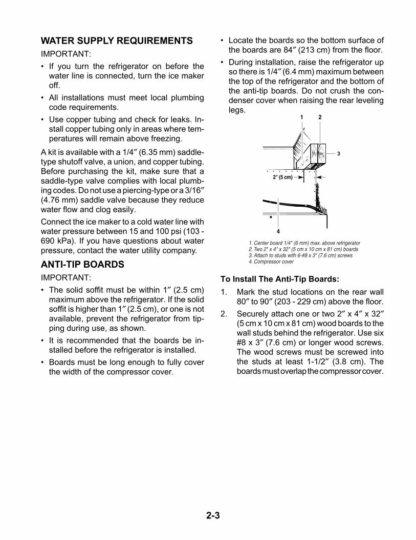
• The solid soffit must be within 1″ (2.5 cm)maximum above the refrigerator. If the solidsoffit is higher than 1″ (2.5 cm), or one is notavailable, prevent the refrigerator from tip-ping during use, as shown.
• It is recommended that the boards be in-stalled before the refrigerator is installed.
• Boards must be long enough to fully coverthe width of the compressor cover.
21
3
2" (5 cm)
4
1. Center board 1/4" (6 mm) max. above refrigerator2. Two 2" x 4" x 32" (5 cm x 10 cm x 81 cm) boards3. Attach to studs with 6-#8 x 3" (7.6 cm) screws4. Compressor cover
To Install The Anti-Tip Boards:
1. Mark the stud locations on the rear wall80″ to 90″ (203 - 229 cm) above the floor.
2. Securely attach one or two 2″ x 4″ x 32″(5 cm x 10 cm x 81 cm) wood boards to thewall studs behind the refrigerator. Use six#8 x 3″ (7.6 cm) or longer wood screws.The wood screws must be screwed intothe studs at least 1-1/2″ (3.8 cm). Theboards must overlap the compressor cover.
• Locate the boards so the bottom surface ofthe boards are 84″ (213 cm) from the floor.
• During installation, raise the refrigerator upso there is 1/4″ (6.4 mm) maximum betweenthe top of the refrigerator and the bottom ofthe anti-tip boards. Do not crush the con-denser cover when raising the rear levelinglegs.
2-4
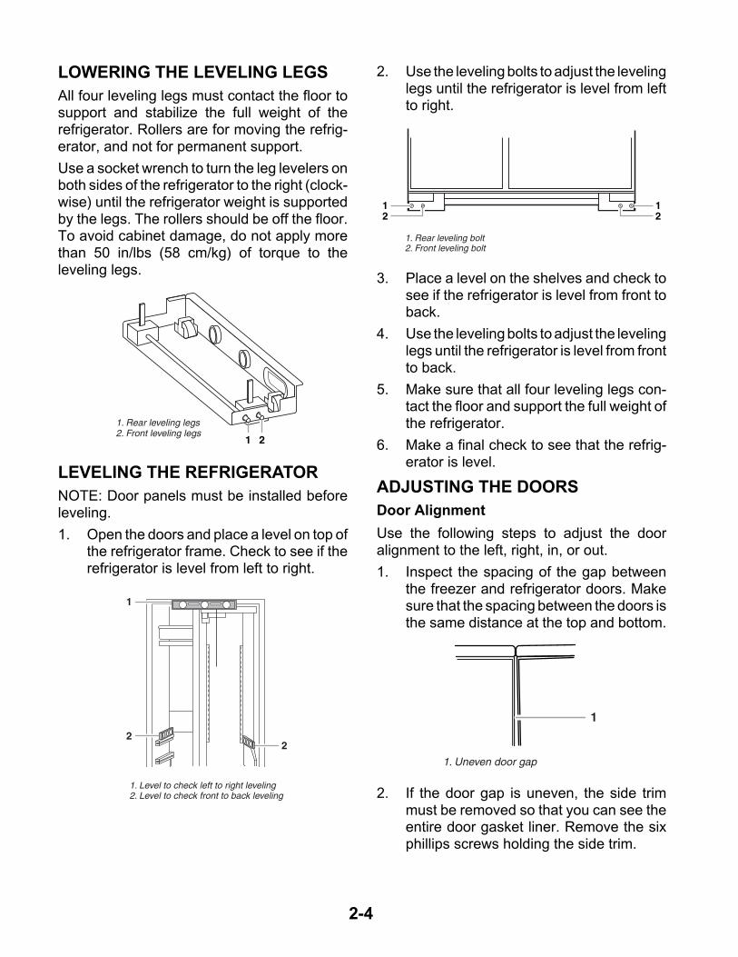
LOWERING THE LEVELING LEGS
All four leveling legs must contact the floor tosupport and stabilize the full weight of therefrigerator. Rollers are for moving the refrig-erator, and not for permanent support.
Use a socket wrench to turn the leg levelers onboth sides of the refrigerator to the right (clock-wise) until the refrigerator weight is supportedby the legs. The rollers should be off the floor.To avoid cabinet damage, do not apply morethan 50 in/lbs (58 cm/kg) of torque to theleveling legs.
1 2
1. Rear leveling legs2. Front leveling legs
LEVELING THE REFRIGERATOR
NOTE: Door panels must be installed beforeleveling.
1. Open the doors and place a level on top ofthe refrigerator frame. Check to see if therefrigerator is level from left to right.
2. Use the leveling bolts to adjust the levelinglegs until the refrigerator is level from leftto right.
3. Place a level on the shelves and check tosee if the refrigerator is level from front toback.
4. Use the leveling bolts to adjust the levelinglegs until the refrigerator is level from frontto back.
5. Make sure that all four leveling legs con-tact the floor and support the full weight ofthe refrigerator.
6. Make a final check to see that the refrig-erator is level.
ADJUSTING THE DOORS
Door Alignment
Use the following steps to adjust the dooralignment to the left, right, in, or out.
1. Inspect the spacing of the gap betweenthe freezer and refrigerator doors. Makesure that the spacing between the doors isthe same distance at the top and bottom.
1
22
1. Level to check left to right leveling2. Level to check front to back leveling
12
12
1. Rear leveling bolt2. Front leveling bolt
1
1. Uneven door gap
2. If the door gap is uneven, the side trimmust be removed so that you can see theentire door gasket liner. Remove the sixphillips screws holding the side trim.

2-5
3. Loosen the four 3/8″ hex-head screws ontop of both door hinges.
1
1. Mounting screws
4. Adjust the hinges so that the door gap isthe same distance at the top and bottom.
5. Check the side door gasket gap. Makesure that the distance is the same at thetop and bottom. Adjust the hinges, asnecessary.
6. Recheck the front door gap spacing tomake sure that it is properly aligned andeven.
7. Tighten the top hinge screws securely.
8. Reinstall the side door trim.
Door Height Adjustment
Use the following steps to adjust the doorheight up or down after the doors have beenleveled.
1. Open the freezer or refrigerator door andlocate the hinge assembly at the bottom ofthe door.
1. Locking plate2. Door stop screw3. Bushing
2. Use an allen wrench and remove the doorstop screw and locking plate from thebottom door hinge.
3. Use an open-end wrench and turn thebushing, located under the bottom of thehinge, to the left to raise the door, or to theright to lower the door.
4. Replace the locking plate and door stopscrew. Turn the bushing slightly to alignthe hinge and locking plate screw holes.

2-6
Door Swing Adjustment
1. Open the refrigerator and freezer doorsand make sure that they open freely. If adoor opens too wide, remove the doorstop screw from the bottom hinge.
1. Door stoop setscrew (130° position)2. 110 ° position.3. 90 ° position.
1 2 3
2. Move the door to the desired open posi-tion, and then reinstall the door stop screwat one of the three holes that is closest tothe desired position.
3-1
THEORY OF OPERATION
OVERVIEWThe KitchenAid Built-In Refrigerator ConstantFlow Temperature Management System usestwo thermistors to monitor temperature changesinside the refrigerator and freezer compart-ments. The electronic control manages theoperation of the variable capacity compressor(VCC), a variable speed evaporator fan motor,and a variable position air door. The air doorallows independent temperature control of therefrigerator and freezer compartments.
The electronic control seeks the most efficientmeans possible to maintain temperatures as itcontrols the operation and speed of the com-pressor and the evaporator fan motor. Higherfan speed is used before increasing the com-pressor speed to minimize power consump-tion. A nearly constant run time is sought at thelowest possible fan and compressor speed.
Freezer temperatures can be set from 9°F to–9°F (–13°C to –23°C). Refrigerator tempera-tures can be set from 46°F to 32°F, (8°C to0°C).
The Adaptive Defrost Control (ADC) portion ofthe electronic control utilizes “pulsed defrost”technology to perform the defrost function (seepage 3-4).
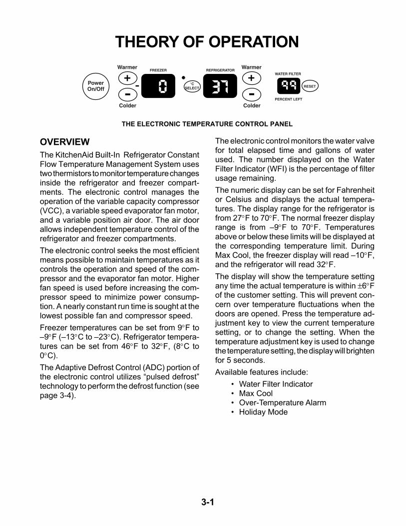
THE ELECTRONIC TEMPERATURE CONTROL PANEL
PowerOn/Off
Warmer
Colder
Warmer
Colder
FREEZER REFRIGERATORWATER FILTER
PERCENT LEFT
RESET°C
SELECT
The electronic control monitors the water valvefor total elapsed time and gallons of waterused. The number displayed on the WaterFilter Indicator (WFI) is the percentage of filterusage remaining.
The numeric display can be set for Fahrenheitor Celsius and displays the actual tempera-tures. The display range for the refrigerator isfrom 27°F to 70°F. The normal freezer displayrange is from –9°F to 70°F. Temperaturesabove or below these limits will be displayed atthe corresponding temperature limit. DuringMax Cool, the freezer display will read –10°F,and the refrigerator will read 32°F.
The display will show the temperature settingany time the actual temperature is within ±6°Fof the customer setting. This will prevent con-cern over temperature fluctuations when thedoors are opened. Press the temperature ad-justment key to view the current temperaturesetting, or to change the setting. When thetemperature adjustment key is used to changethe temperature setting, the display will brightenfor 5 seconds.
Available features include:
• Water Filter Indicator• Max Cool• Over-Temperature Alarm• Holiday Mode

3-2
Freezer Temperature Control —Temperature Decreasing
When the freezer temperature begins to de-crease, the process will reverse. The compres-sor speed decreases, followed by the evapo-rator fan speed.
Refrigerator Temperature Control —Temperature Increasing
When the refrigerator calls for cooling whilethe freezer is satisfied, the air door begins toopen, and the evaporator fan starts to run atminimum speed. If the temperature continuesto rise, the air door will continue to open. If thetemperature continues to rise after the air dooris fully open, the evaporator fan speed willgradually increase to a maximum of 3000 rpm.If the temperature continues to rise, the com-pressor starts to run, or if it has already beenrunning, begins to increase in speed.
Refrigerator Temperature Control —Temperature Decreasing
As the refrigerator temperature approaches theselected setting, the control compares the tem-peratures in both compartments to determinewhich compartment will control the fan speed.If the freezer is further from the selected tem-perature setting, it controls the fan speed, andthe air door begins to close, thus reducing theairflow to the refrigerator.
If the freezer is satisfied, the air door remainsopen, and the fan speed begins to decrease.When the selected temperature setting isreached, the air door closes.
TEMPERATURE CONTROLThe electronic control checks the resistance ofthe thermistors, and compares it to both thecustomer temperature settings and the lastthermistor reading taken. This information isused to determine when to begin a coolingoperation, and if a change is necessary in thedamper setting, or the evaporator fan or com-pressor speed.
When a warm refrigerator is first put into acooling mode, the air door partially opens, andthe compressor and evaporator fan motorsstart to run at maximum rpm. The air door willgradually move to its fully open position.
As the actual temperature in the refrigeratornears the selected temperature setting, theelectronic control compares the temperaturesin both compartments. The compartment thathas the greatest need for cooling, will controlthe speed of the evaporator fan motor.
Freezer Temperature Control —Temperature Increasing
When the freezer calls for cooling, the com-pressor begins to run at minimum rpm, (see thechart on page 3-3), and the evaporator fanbegins to run at 2000 rpm. The compressorand evaporator speeds are continuously up-dated. Speed changes are made based on:
• The difference between the actual tempera-ture and the selected temperature settings.
• The rate of temperature change.
If the temperature increases 4°F above theselected temperature setting, the evaporatorfan speed begins to gradually increase. Theevaporator fan motor reaches the maximumspeed of 3000 rpm at 5°F above the selectedtemperature setting, and the compressor speedbegins to gradually increase. A maximum com-pressor speed of 4500 rpm will be reached at9°F above the selected temperature setting.
3-3
COMPRESSORThe main control board supplies a 5 vdc, peak-to-peak square wave, at 54 to 150 Hz, to theinverter board. A standard VOM will read ap-proximately 2.5 vdc. The inverter board sup-plies the variable capacity compressor withthree-phase 230 vac. Varying the frequencyto the inverter board, and not the voltage,changes the speed of the compressor. Thecompressor can run at speeds of 1620 to 4500rpm.
NOTE: It is not necessary, nor is it recom-mended, to test the output of the inverter board.
While the compressor is running, its speed iscontinuously updated. Speed is determinedafter analyzing two factors:
• The difference between the actual tempera-ture and the selected temperature settings.
• The rate of temperature change.
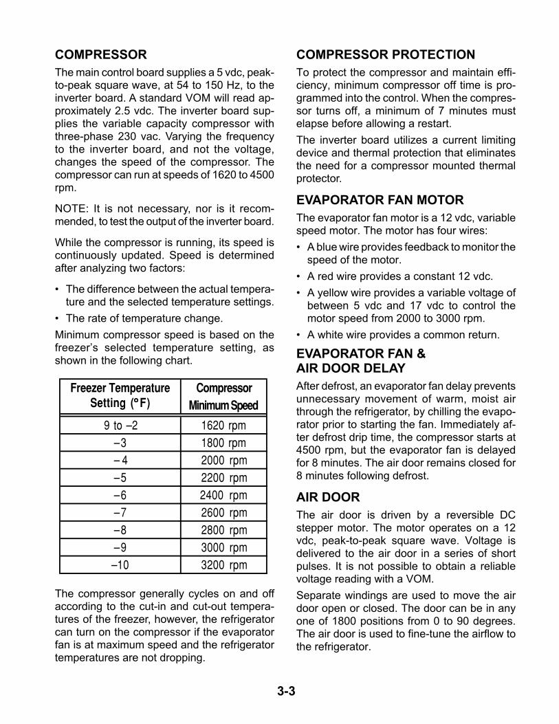
Minimum compressor speed is based on thefreezer’s selected temperature setting, asshown in the following chart.
The compressor generally cycles on and offaccording to the cut-in and cut-out tempera-tures of the freezer, however, the refrigeratorcan turn on the compressor if the evaporatorfan is at maximum speed and the refrigeratortemperatures are not dropping.
COMPRESSOR PROTECTIONTo protect the compressor and maintain effi-ciency, minimum compressor off time is pro-grammed into the control. When the compres-sor turns off, a minimum of 7 minutes mustelapse before allowing a restart.
The inverter board utilizes a current limitingdevice and thermal protection that eliminatesthe need for a compressor mounted thermalprotector.
EVAPORATOR FAN MOTORThe evaporator fan motor is a 12 vdc, variablespeed motor. The motor has four wires:
• A blue wire provides feedback to monitor thespeed of the motor.
• A red wire provides a constant 12 vdc.
• A yellow wire provides a variable voltage ofbetween 5 vdc and 17 vdc to control themotor speed from 2000 to 3000 rpm.
• A white wire provides a common return.
EVAPORATOR FAN &AIR DOOR DELAYAfter defrost, an evaporator fan delay preventsunnecessary movement of warm, moist airthrough the refrigerator, by chilling the evapo-rator prior to starting the fan. Immediately af-ter defrost drip time, the compressor starts at4500 rpm, but the evaporator fan is delayedfor 8 minutes. The air door remains closed for8 minutes following defrost.
AIR DOORThe air door is driven by a reversible DCstepper motor. The motor operates on a 12vdc, peak-to-peak square wave. Voltage isdelivered to the air door in a series of shortpulses. It is not possible to obtain a reliablevoltage reading with a VOM.
Separate windings are used to move the airdoor open or closed. The door can be in anyone of 1800 positions from 0 to 90 degrees.The air door is used to fine-tune the airflow tothe refrigerator.
Freezer Temperature CompressorSetting (°°°°F) Minimum Speed
9 to –2 1620 rpm–3 1800 rpm– 4 2000 rpm–5 2200 rpm–6 2400 rpm–7 2600 rpm–8 2800 rpm–9 3000 rpm–10 3200 rpm

3-4
The refrigerator temperature determines theopening of the air door. When the refrigeratorrequires cooling, if the evaporator fan motor isalready running for the freezer, the air doorpartially opens, and then adjusts, if necessary.While the refrigerator is cooling, the door willbe adjusting continuously to maintain or re-cover refrigerator temperature.
ADAPTIVE DEFROSTThe adaptive defrost control allows the unit toenter a defrost mode only when it is needed.When powered up for the first time, the controlinitiates a defrost cycle after 8 hours of com-pressor run time. By monitoring the duration ofdefrost heating time and compressor run time,the control will continuously adapt the timebetween defrosts to optimize efficiency. Timebetween defrost periods will vary between 8and 100+ hours.
Defrost will occur immediately when the com-pressor has run at 4000 rpm or greater for 1hour, and 8 hours have elapsed since the lastdefrost.
PULSED DEFROSTFor the first 2 minutes of defrost, the heater ison continuously. It will then cycle off for 1minute, and back on for 2 minutes. The heaterwill continue to cycle at this ratio until thebimetal opens, or until 33 minutes has elapsed.At this point, heat is discontinued, and a4-minute “drip time” begins. This allows thewater to drain before the unit returns to acooling mode. Maximum defrost time, (pulsedheat on/off time + drip time) is 37 minutes.
When entering a defrost cycle, if the bimetal isopen, the time to defrost is reset to 8 hours, andthe control will time through the entire 37 minutedefrost period. During diagnostics this will al-low a technician time to look for heater opera-tion, and if necessary, bypass the bimetal.
POWER INTERRUPTIONAfter a power interruption, the following eventswill occur:
• The unit returns to the same operating modeand settings in use prior to the power inter-ruption. If the unit was off, it remains off.
• Initially, the compressor, evaporator fan, andcondenser fan motors will be off.
• The air door will close, and then adjust to theproper opening. The evaporator fan startswhen the air door opens.
• The adaptive defrost control resets the com-pressor run time counter to 0, and if thefreezer is above 20°F, the time to defrost isset to 8 hours.
• If the freezer temperature is below 12°F, thecompressor starts after a delay of 7 minutes.If the freezer temperature is above 12°F, thecompressor starts immediately.
FAILURE DEFAULTSIn the event of a thermistor, or keypad failure,the control uses one of the following defaultmodes, which will continue until the failure iscorrected.
Refrigerator Thermistor
If the control senses an open or a shortedthermistor, the air door and the evaporator fanmotor will begin to operate on a timed on andoff cycle, based on current selected tempera-ture settings. The evaporator fan motor will runwhen the air door is open.
At mid-settings of 37°F / 0°F, the air door willopen for 16 minutes, and close for 30 minutes.Setting the freezer colder, or the refrigeratorwarmer, will reduce the door-open time. Set-ting the freezer warmer, or the refrigeratorcolder, will increase the door-open time.

3-5
Freezer Thermistor
If the control senses an open or a shorted ther-mistor, the compressor and the evaporator fanmotor will begin to operate on a timed on andoff cycle. The cycle time is based on currentselected temperature settings.
At mid-settings of 37°F / 0°C, the compressorand the evaporator fan motors will run for 35minutes, and be off for 25 minutes. Setting thefreezer colder will increase the run time. Set-ting the freezer warmer will decrease the runtime.
The compressor will run at minimum speed.The evaporator fan will also run at minimumspeed, unless the refrigerator compartmentrequests a higher speed.
Keypad
If the control detects that the keypad is notworking, it reverts to the default temperaturesettings of 37°F in the refrigerator, and 0°F inthe freezer.
Evaporator Fan Motor
If the evaporator fan motor malfunctions, thecompressor will run at 4500 rpm for an indefi-nite period, except during the defrost periods.The “Call Service Alarm” will sound until thefailure has been corrected.
ELECTRONIC CONTROLTHERMAL SHUTOFFThe electronic control utilizes an on-board ther-mistor to shut the compressor off if the tem-perature rises above 160°F (71°C). When thetemperature drops to 130°F (55°C), the com-pressor returns to normal operation. This cyclecontinues indefinitely until the cause of the hightemperature has been corrected.
If this cycle is repeated four times within 24hours, the “Call Service” indicator lights, andthe alarm sounds.
MAX COOL MODEMax Cool changes the refrigerator tempera-ture setting to 32°F (0°C) and the freezer to–10°F (–23°C) for 24 hours. During Max Cool,the freezer and refrigerator temperature dis-plays show the new temperature settings, notthe actual temperatures.
In most cases the motors run 100% for morethan 1 hour. The control returns to the previoususer setting after 24 hours, or any time thetemperature settings are changed.
AUTOMATIC MAX ICEAutomatic Max Ice operates any time the icemaker water valve is energized. The durationof Automatic Max Ice is 1-1/2 hours. DuringAutomatic Max Ice the following occurs:
• The freezer display shows the user tempera-ture settings and not the actual temperature.
• The freezer temperature setting changes to–9°F (–23°C).
• The evaporator fan runs at 3000 rpm.
• The compressor runs the entire 1-1/2 hourmode. Speed is determined by the differ-ence between actual freezer temperatureand -9°F (-23°C).
HOLIDAY MODEThe Holiday Mode may be used for the follow-ing occasions:
• On vacation.
• Religious observance (Sabbath Mode).
When the Holiday Mode is selected, the corre-sponding green LED flashes for 2 seconds,and then remains on, to indicate that the fea-ture is activated.

3-6
In the Holiday Mode the following occurs:
• Temperature selections remain at the cur-rent setting, but are not displayed.
• The Water Filter Indicator is not displayed,but monitoring continues.
• The audible signals are disabled.
• The ice maker is disabled.
• The interior lights are disabled.
• The temperature displays and all of the LEDswill be off, except for the Holiday Mode LED.The Holiday Mode LED will illuminate re-gardless of the door position.
• Keypad operation is disabled, with the ex-ception of the Holiday Mode key, or thePower On/Off key.
The Holiday Mode will be cancelled if one of thefollowing occurs:
• Pressing the Power On/Off, or Holiday Modekeypads.
• Failure of both thermistors.
• No feedback from the evaporator fan motor.
• Temperatures that are 15°F above user set-tings in either compartment.
When the Holiday Mode is cancelled, the Holi-day Mode LED turns off, and the control re-verts to the settings in use prior to activation.All inactive devices are restored, and the Wa-ter Filter Indicator is updated.
The Adaptive Defrost Control function is noteffected by use of the Holiday Mode.
OVER-TEMPERATURE ALARMThe Over-Temperature Alarm sounds, and theindicator light flashes when either the refrig-erator temperature exceeds 48°F (9°C), or the
freezer temperature exceeds 15°F (–9°C) forover 1-1/2 hours. The appropriate temperaturedisplay flashes to show the user which com-partment is effected. The alarm stops if thetemperature(s) returns to normal, but the redOver-Temperature indicator and temperaturedisplay will continue to flash. Pushing the Over-Temperature Reset key turns off the Alarm and/or indicator, and resets the Over-TemperatureTimer to zero.
CALL SERVICE ALARMCall Service is a visual and audio signal thatalerts the user that the refrigerator needs ser-vice. The Call Service Alarm will sound when:
• Both thermistors have failed.
• The evaporator fan motor loses its feedbacksignal.
• An over-temperature condition occurs for 3hours or more.
DOOR OPEN ALARMIf either door is left open for more than 10 min-utes, the interior lights will be disabled, theDoor Open icon will flash, and the alarm willsound. If the door is closed during the alarmoperation, the alarm will reset, but the icon willcontinue to flash until the temperature in therefrigerator drops below 45°F (7°C) and thefreezer is below 15°F (–9°C). Pressing theOver-Temperature Alarm/Reset key resets theAlarm and the flashing Icon.
SALES DEMONSTRATION MODEThis mode provides a sequential display of thetemperature displays and feature LEDs. Toenter the Demonstration Mode, press and holdthe Max Cool and Power On/Off keys for 2seconds. If the refrigerator or freezer door isopen for 10 minutes, the interior lights will turnoff.

3-7
AIR CIRCULATIONIn order to ensure the proper refrigerator andfreezer compartment temperatures, air mustbe able to flow between the two sections.
Air enters the bottom of the freezer compart-ment and moves up through the evaporator.Some of the cooled air from the evaporator isdirected back into the freezer, and the restgoes into the refrigerator through the motor-ized air door. The refrigerator air then returns tothe freezer through the bottom air return (seethe illustration below).
It is important not to block any of the vents withfood items. If the vents are blocked, airflow willbe restricted, and the temperature manage-ment system will not function properly.
IMPORTANT: Because air circulates betweenboth sections, any odors formed in one sec-tion will transfer to the other. Keep both sec-tions clean, and wrap or cover foods tightly toprevent odors from occurring.

3-8
SEALED SYSTEM SCHEMATIC
MULLION HEAT LOOP
CONDENSATE PAN HEAT LOOP
CONDENSER
FILTER-DRIER
CAPILLARYTUBE
HEAT EXCHANGER
COMPRESSOR
SUCTION LINE DISCHARGE
EVAPORATOR

4-1
COMPONENT LOCATIONS
This section instructs you on how to service each component inside the refrigerator/freezer. Thecomponents and their locations are shown below.
COMPONENT ACCESS
Freezer Thermistor
Evaporator Fan MotorBimetal
Defrost HeaterEvaporator
RefrigeratorThermistor
Touch Control Assembly
Ice Maker
Auger Motor
Freezer DoorSwitch
Inverter Assembly
Compressor
Condenser Fan Motor
Refrigerator Door Switch
Power Switch
Main ControlBoard Assembly
Filter/Drier
MotorizedAir Door
WaterReservoir
Water Valve
4-2
REMOVING THE UNIT COMPARTMENT COVER
NOTE: Sharp edges may be present.
1. Unplug the refrigerator or disconnect thepower.
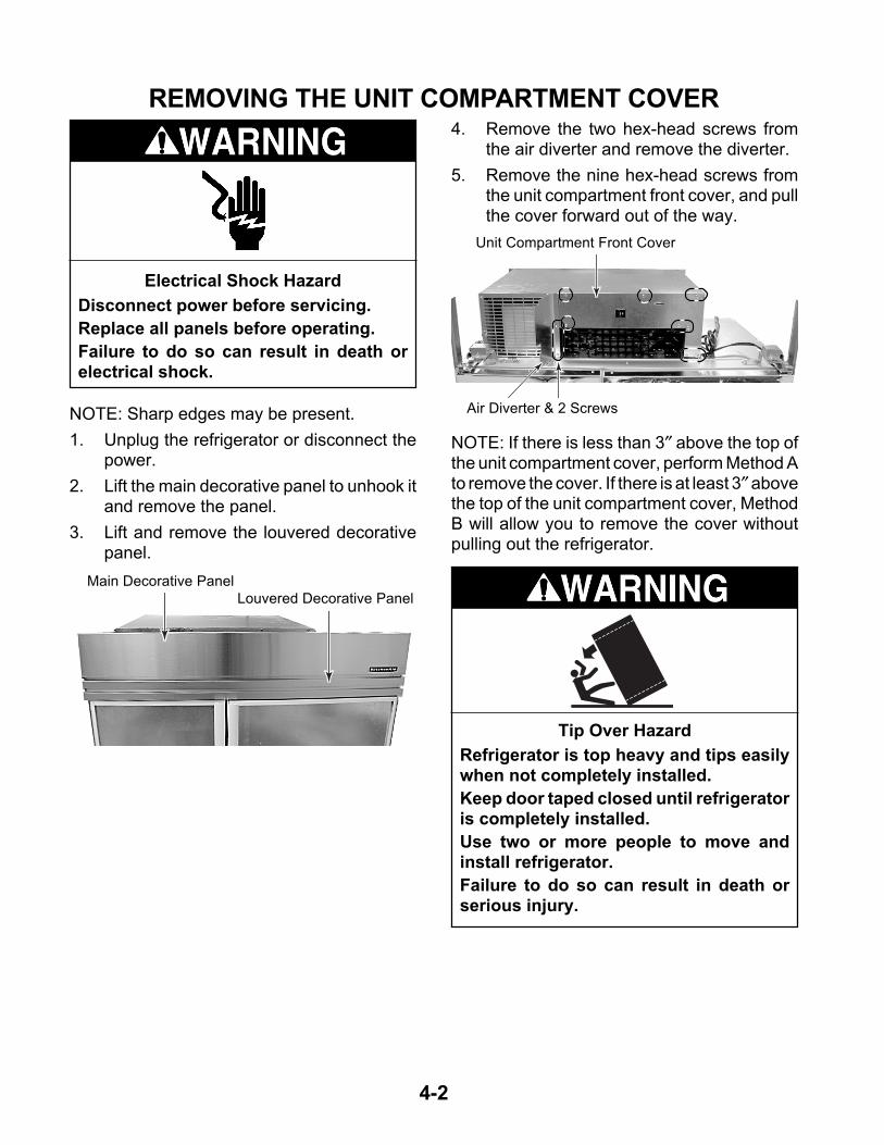
2. Lift the main decorative panel to unhook itand remove the panel.
3. Lift and remove the louvered decorativepanel.
Electrical Shock Hazard
Disconnect power before servicing.
Replace all panels before operating.
Failure to do so can result in death orelectrical shock.
Main Decorative Panel
Louvered Decorative Panel
4. Remove the two hex-head screws fromthe air diverter and remove the diverter.
5. Remove the nine hex-head screws fromthe unit compartment front cover, and pullthe cover forward out of the way.
Air Diverter & 2 Screws
Unit Compartment Front Cover
NOTE: If there is less than 3″ above the top ofthe unit compartment cover, perform Method Ato remove the cover. If there is at least 3″ abovethe top of the unit compartment cover, MethodB will allow you to remove the cover withoutpulling out the refrigerator.
Tip Over Hazard
Refrigerator is top heavy and tips easilywhen not completely installed.
Keep door taped closed until refrigeratoris completely installed.
Use two or more people to move andinstall refrigerator.
Failure to do so can result in death orserious injury.

4-3
METHOD A
1. Pull the refrigerator out of its mountinglocation so you can access the rear of theunit.
2. Remove the left and right hex-head screws(one on each side) from the front cornersof the unit compartment cover.
METHOD B
1. Remove the left and right hex-head screws(one on each side) from the front cornersof the unit compartment cover (see the topleft photo).
2. Remove the four hex-head screws (two oneach side) from the rear flanges of the unitcompartment cover. NOTE: You will needa 24″ hex-head socket extension with amagnetic tip to remove these screws.
3. Remove the left and right hex-head screwsfrom the rear channels of the unit compart-ment cover.
Right CornerScrew
4. Lift the unit compartment cover up, andpull it forward off the refrigerator.
Left Rear Channel Screw
3. Lift the unit compartment cover up, andpull it forward off the refrigerator.
REASSEMBLY NOTE: When you reinstall theunit compartment cover, make sure that thetwo unit compartment cover tabs slide underthe rear cover flange, as shown below. This willprovide the proper air flow.
24″ Extension
Slide Tabs Under Rear Flanges
Rear Cover Flanges
Unit CompartmentCover

4-4
REMOVING A DOOR SWITCH, THE POWER SWITCH,THE INVERTER ASSEMBLY, AND
THE MAIN CONTROL BOARD ASSEMBLY
NOTE: Sharp edges may be present.
1. Unplug the refrigerator or disconnect thepower.
2. Remove the main and louvered decora-tive panels (see page 4-2).
Electrical Shock Hazard
Disconnect power before servicing.
Replace all panels before operating.
Failure to do so can result in death orelectrical shock.
Hex-Head Bolts
Bracket
b) Remove the two hex-head screws fromthe door switch cover and remove thecover.
Door Switch Cover Screw (1 of 2)
c) Disconnect the wire connectors fromthe door switch terminals.
d) Press in on the locking arms and pushthe switch out of the bracket.
Wire Connectors
Locking Arm
Door Switch
3. To remove a door switch (Original De-sign):
a) Remove the two hex-head bolts fromthe door switch bracket and turn thebracket over.
Power Switch
Main Control Board Assembly
Inverter Assembly

4-5
4. To remove a door switch (Revised De-sign):
a) Remove the two hex-head screws fromthe door switch cover and remove thecover.
Door Switch Cover Screws
b) Disconnect the wire connectors fromthe door switch terminals.
c) Press in on the locking arms and pushthe switch out of the bracket.
Door Switch
5. To remove the power switch:
a) Remove the unit compartment frontcover, pull the cover forward, and turnit over (see step 5 on page 4-2 for theprocedure).
b) Remove the four wire connectors fromthe power switch terminals.
c) Press in on the locking arms and pushthe switch out of the cover opening.
Power Switch
LockingArms Locking
Arms
6. To remove the inverter assembly:
a) Remove the two hex-head screws fromthe air diverter and remove the diverter.
b) Remove the three remaining hex-headscrews from the front guard and re-move the guard.
Screw
Screw
AirDiverter
FrontGuard
c) Remove the hex-head screw from thefront of the inverter assembly.
Screw
InverterAssembly
Retaining Bracket
Continued on the next page.

4-6
e) Disconnect the two wire connectorsand the hex-head screw from the greenground wire coming from the inverterassembly.
2 Wire Connectors g) Disconnect the green ground wire andthe 3-pin inverter output lead from thecompressor.
h) Loosen the strain relief screw from thecompressor terminal cover, remove thewire, and remove the inverter assem-bly.
f) Remove the compressor terminal cover.To remove the cover, insert a flat-bladedscrewdriver into the top slot, push downon the screwdriver to release the catch,and then rotate the cover forward at thetop and lift it off the bottom catch.
CompressorTerminal Cover
GroundWire Screw
Ground Wire& 3-Pin Lead
Cover Strain Relief
d) Pull the inverter assembly forward so itis free of the retaining bracket, rotatethe box so you can access the rearmounting screw, and remove the screw.
RearScrew
Retaining Bracket

4-7
Electrical Shock Hazard
Connect green ground wire to groundscrew.
Failure to do so can result in death orelectrical shock.
REASSEMBLY NOTE: Be sure to reconnectthe green ground wires; one to the compressorterminal, and the other to the chassis (see theprevious steps).
7. To remove the main control board as-sembly:
a) Remove the unit compartment cover(see pages 4-2 & 4-3 for the proce-dures).
b) Remove the two hex-head screws fromthe rear of the main control board as-sembly enclosure, and position it soyou can access the board.
c) Remove the wire connectors from themain control board assembly.
Wire Connectors
Screws At Rear Of Enclosure
d) Remove the main control board fromthe five standoffs. Press in on the lock-ing tab on each standoff to release theboard.
Press Locking TabOn Standoff

4-8
REMOVING THE CONDENSER FAN MOTOR
NOTE: Sharp edges may be present.
1. Unplug the refrigerator or disconnect thepower.
2. Remove the main and louvered decora-tive panels (see page 4-2).
3. Remove the unit compartment cover (seepages 4-2 & 4-3 for the procedures).
Electrical Shock Hazard
Disconnect power before servicing.
Replace all panels before operating.
Failure to do so can result in death orelectrical shock.
8. Remove the two hex-head screws fromthe condenser fan motor and remove themotor from the bracket.
Condenser Fan Motor
Viewed From Back Of Unit
WireConnector
4. Remove the two hex-head screws fromthe fan motor bracket (see the photo at thetop of the next column).
5. Disconnect the wire connector from thecondenser fan motor.
Fan Motor Bracket Screws
6. Lay the condenser fan motor on a worksurface with the fan blade facing up.
7. Remove the speed nut from the condenserfan blade and remove the blade from themotor shaft. NOTE: Be sure to position thefan blade with the “Nut Side” facing asshown when you reinstall it later.
Nut Side
Speed Nut
Motor Screws

4-9
REMOVING THE COMPRESSOR AND FILTER/DRIER
NOTE: Sharp edges may be present.
1. Unplug the refrigerator or disconnect thepower.
2. Remove the main and louvered decora-tive panels (see page 4-2).
3. Remove the unit compartment cover (seepages 4-2 & 4-3 for the procedures).
NOTE: The compressor location is shown onpage 4-8.
4. Remove the compressor terminal cover.To remove the cover, insert a flat-bladedscrewdriver into the top slot, push down onthe screwdriver to release the catch, andthen rotate the cover forward at the topand lift it off the bottom catch.
Electrical Shock Hazard
Disconnect power before servicing.
Replace all panels before operating.
Failure to do so can result in death orelectrical shock.
CompressorTerminal Cover
7. Access the sealed system and dischargethe refrigerant into an approved recoverysystem.
8. Unbraze the suction and discharge linesfrom the compressor.
9. Cut the filter/drier from the system (do notuse a torch to remove the filter/drier).
6. Loosen the strain relief screw from thecompressor terminal cover and removethe wire.
Ground Wire& 3-Pin Lead
Cover Strain Relief
10. Remove the four mounting bolts and rub-ber grommets from the compressor.
11. Lift the old compressor from the refrigera-tor and replace it.
5. Disconnect the green ground wire and the3-pin inverter output lead from the com-pressor (see the photo at the top right).
Filter/Drier
Suction
Discharge

4-10
6. Lift and unhook the two evaporator covertabs, then lower the cover until the topedge clears the air duct, and slide thecover up and out of the freezer.
REMOVING THE BIMETAL, THE EVAPORATOR FANMOTOR, THE DEFROST HEATER, AND THE EVAPORATOR
NOTE: Sharp edges may be present.
1. Unplug the refrigerator or disconnect thepower.
2. Open the freezer door.
3. Remove the freezer shelves that are overthe evaporator cover.
4. Remove the indicated two shelf mountingstuds.
EvaporatorCover
Shelf Studs
5. Remove the eight hex-head screws fromthe evaporator cover.
Screws (2 of 8)
Unhook EvaporatorCover Tabs
7. To remove the bimetal:
a) Unclip the bimetal from the evaporatorinlet tubing.
b) Follow the instructions that were sup-plied with the replacement bimetal toconnect the wires.
Bimetal
Electrical Shock Hazard
Disconnect power before servicing.
Replace all panels before operating.
Failure to do so can result in death orelectrical shock.
Clip

4-11
8. To remove the evaporator fan motor:
a) Pull the fan blade off the motor shaft.
b) Unclip the motor.
c) Disconnect the wire connector from theterminals.
Unclip Motor
Pull Fan Blade Off Motor Shaft
Wire Connector
d) Remove the isolator from the motor.
Isolator
EvaporatorFan Motor
9. To remove the defrost heater:
a) Remove the two hex-head screws fromthe evaporator fan motor shroud.
b) Lift the evaporator fan motor shroudand disconnect the evaporator fan motorconnector (see the photo to the left).
c) Unclip the bimetal from the evaporatorinlet tubing.
Evaporator Fan MotorShroud Screws
Foam Blocks
e) Remove the evaporator fan motorshroud and the two side foam blocks.
Continued on the next page.
Bimetal
d) Disconnect the terminal connector andthe two defrost heater wires from theharness connector.
Defrost Heater Wires
Terminal Connector

4-12
j) Unfasten the two metal clips from theright side, and slide the defrost heaterdown and off the evaporator.
g) Remove the foam block from the rightside of the evaporator.
NOTE: Be very careful not to over-bendthe refrigerant tubing.
h) Lift the evaporator up slightly and un-hook it from the liner, then pull thebottom of the evaporator toward thefront of the unit.
Right Side Clip
Defrost Heater
Right Foam Block
f) Remove the hex-head screws from theright evaporator cover mounting bracketand remove the bracket. Be careful notto drop the screws down the drain holeat the bottom of the liner. Cover the holewith a cloth.
Right Evaporator CoverMounting Bracket
i) Bend the two hangers at the bottom ofthe evaporator.
Bend The Two Hangers

4-13
10. To remove the evaporator:
a) Remove the defrost heater from theevaporator (see pages 4-11 & 4-12).
b) Access the sealed system and dis-charge the refrigerant into an approvedrecovery system.
c) Remove and replace the evaporator.
REASSEMBLY NOTES:
1. The evaporator fan motor shroud has afoam insert on each side. Note the positionof these inserts in the photo and reinstallthem correctly, as shown.
2. Be sure to reinstall the right foam block atthe location shown below.
DefrostHeater
Evaporator
Evaporator Fan Motor Shroud
Foam Blocks
Right Foam Block

4-14
REMOVING THE TOUCH/DISPLAY BOARD& THE MOTORIZED AIR DOOR
NOTE: Sharp edges may be present.
1. Unplug the refrigerator or disconnect thepower.
2. Open the refrigerator door and remove theitems from the top shelf. If necessary,remove the top shelf so you can easilyaccess the touch control assembly or themotorized air door. The locations areshown below.
Electrical Shock Hazard
Disconnect power before servicing.
Replace all panels before operating.
Failure to do so can result in death orelectrical shock.
c) Disconnect the wire connector from theend of the touch/display board.
3. To remove the touch/display board:
a) Remove the three hex-head screwsfrom the back of the touch control as-sembly and lower the assembly.
Touch Control Assembly
b) Disconnect the two wire connectorsfrom the touch control assembly andremove the assembly from the refrig-erator.
Wire Connectors
Wire Connector
d) Unclip the touch/display board from thelocking tabs and remove the board.
Board Clips
Motorized Air Door
3 Screws At Back Of Control

4-15
4. To remove the motorized air door:
a) Remove the hex-head screws from themotorized air door cover and removethe cover.
c) Disconnect the wire connector from themotorized air door and remove it. RE-ASSEMBLY NOTE: Be sure to positionthe motorized air door with the motorand wires as shown in the bottom leftphoto.
b) Pull the motorized air door out of therefrigerator liner opening.
Screw
Motorized Air Door Cover Motorized Air Door Wire Connector
Screw

4-16
REMOVING THE ICE MAKER ANDTHE AUGER MOTOR & CRUSH/CUBE SOLENOID
Electrical Shock Hazard
Disconnect power before servicing.
Replace all panels before operating.
Failure to do so can result in death orelectrical shock.
NOTE: Sharp edges may be present.
1. Unplug the refrigerator or disconnect thepower.
2. Open the freezer door and remove the icemaker shelf and the ice bin.
3. To remove the ice maker:
a) Remove the bottom screw from the icemaker bracket.
Ice Maker
Auger Assembly
Bottom Bracket Screw
b) Loosen the two top ice maker bracketscrews.
c) Lift the brackets at the top of the icemaker off the screws, disconnect theelectrical harness connector, and re-move the ice maker.
Top BracketScrews
Water Fill TubeInside Fill Cup
NOTE: When you reinstall the ice maker, makesure that the end of the water fill tube is posi-tioned inside the fill cup (see the photo above).
Ice Bin
Ice MakerShelf

4-17
4. To remove the auger motor or crush/cube solenoid:
a) Remove the light shield and the bulbfrom the socket.
b) Remove the four hex-head screws fromthe auger assembly and pull the as-sembly forward.
Light Shield & Bulb
Auger Assembly
c) Disconnect the electrical harness con-nector, and remove the auger assem-bly.
Screws Screws
Harness Connector
d) To remove the auger, unscrew the drivecoupler (left-hand threads) and removeit from the motor shaft.
e) Remove the three auger motor hex-head screws from the housing.
Drive Coupler
Remove
f) Disconnect the wires from the augermotor terminals.
g) Disconnect the wires from the solenoidterminals.
h) Remove the green ground wire fromthe ground terminal.
i) To remove the crush/cube solenoid,remove the two hex-head mountingscrews from the housing (see above).
Auger Motor Wires
Solenoid Screws
Solenoid Wires
Auger MotorScrew (2 of 3)
Ground Wire

4-18
REMOVING A THERMISTOR
NOTE: Sharp edges may be present.
1. Unplug the refrigerator or disconnect thepower.
NOTE: The refrigerator and freezer thermistorsare identical and are removed in the samemanner.
2. Depending on the thermistor, open thefreezer or refrigerator door, and removeany items from the shelf that are in front ofthe thermistor. It may be necessary toremove the shelf as well. The thermistorlocations are shown below.
Electrical Shock Hazard
Disconnect power before servicing.
Replace all panels before operating.
Failure to do so can result in death orelectrical shock.
4. Disconnect the 2-wire connector and re-move the thermistor.
3. Remove the hex-head screw from thethermistor cover. Pull the cover forward atthe screw end, and unhook the tab fromthe slot at the other end of the thermistorcover.
Refrigerator / FreezerThermistor Cover
Screw
Connector
Refrigerator / FreezerThermistor
Freezer Thermistor
Refrigerator Thermistor

4-19
REMOVING A LIGHT SOCKET
NOTE: Sharp edges may be present.
1. Unplug the refrigerator or disconnect thepower.
NOTE: The refrigerator and freezer light sock-ets are identical and are removed in the samemanner.
2. Depending on the light, open the freezeror refrigerator door, and remove any itemsfrom the shelf that are in front of the light.It may be necessary to remove the shelf aswell. The light locations are shown below.
Electrical Shock Hazard
Disconnect power before servicing.
Replace all panels before operating.
Failure to do so can result in death orelectrical shock.
3. Remove the light shield.
4. Remove the bulb from the socket.
5. Grasp the light socket by the roundedportion and pull out on the narrow end,while pressing the locking arm (see thephoto below) with a screwdriver blade.Pull out on the socket until it disengagesfrom the opening.
Press In On Locking Arm At Narrow End
Grasp Rounded Portion Here & Pull Out
6. Disconnect the two wires from the lightsocket terminals.
Wire
Wire
Locking Arm
Freezer Light
Freezer Light
Refrigerator Lights

4-20
REMOVING THE WATER RESERVOIR
Electrical Shock Hazard
Disconnect power before servicing.
Replace all panels before operating.
Failure to do so can result in death orelectrical shock.
NOTE: Sharp edges may be present.
1. Unplug the refrigerator or disconnect thepower.
3. Use the leveling screws and lower therefrigerator onto the four rollers.
Base Grille
NOTE: If the water reservoir tubing locatedinside the refrigerator compartment becomesdamaged, you can cut and splice a new reser-voir in its place using two 5/16″ unions(#4388201). If the tubing located under therefrigerator is defective, it will be necessary toremove the unit from its mounting location torepair it. If that is the case, use the followingprocedure.
2. Remove the two screws from the basegrille and remove the grille.
Screw Screw
Tip Over Hazard
Refrigerator is top heavy and tips easilywhen not completely installed.
Keep door taped closed until refrigeratoris completely installed.
Use two or more people to move andinstall refrigerator.
Failure to do so can result in death orserious injury.
4. Pull the refrigerator out of its mountinglocation.
Leveling ScrewsRear Front
NOTE: The water reservoir and water valvelocations are shown below.
Water Reservoir
Water Valve
Unit Shown Tipped Back 45˚
Leveling Screws

4-21
Pull Tubing Up Through Grommet
6. Use a putty knife, slide the retainer clips offthe door channel, and pull the water lineout from under the channel.
Door Channel
Clip
9. Reach under the front of the refrigeratorand remove the water reservoir outlet tub-ing nut from the water valve and removethe nut from the end of the tubing.
7. Position a container to catch the water inthe next step.
8. Disconnect the nut from the union andremove the nut from the end of the waterreservoir tubing.
Union Nut
5. Unhook the front edge of the drip pan andpull it out the front of the refrigerator.
Unhook Front
10. Remove the crisper and bottom shelvesfrom the refrigerator compartment.
11. Remove the hex-head screw from thewater reservoir tubing strap.
12. Pull the ends of the water reservoir tubingup through the grommet.
Drip Pan
Water Reservoir Tubing Nut
Water Reservoir Tubing Strap

4-22
REMOVING THE WATER VALVE
Electrical Shock Hazard
Disconnect power before servicing.
Replace all panels before operating.
Failure to do so can result in death orelectrical shock.
5. Disconnect the 1/2″ nut from the watervalve inlet.
6. Remove the two hex-head mountingscrews from the water valve mountingbracket.
NOTE: Sharp edges may be present.
1. Unplug the refrigerator or disconnect thepower.
2. Remove the two screws from the basegrille and remove the grille.
3. Turn off the water supply to the refrigera-tor.
Base GrilleScrew Screw
NOTE: The water valve location is shown be-low.
Water Valve
4. Position a container to catch the water inthe next step.
7. Pull the water valve forward and discon-nect the water outlet tubing nut(s).
8. Disconnect the solenoid connector(s)from the water valve terminal(s).
Water Valve
Water ValveInlet Tubing
Water ValveBracket Screws
Solenoid Connectors
Water Outlet Tubing Nuts

4-23
REMOVING THE WATER & ICE DISPENSER
Electrical Shock Hazard
Disconnect power before servicing.
Replace all panels before operating.
Failure to do so can result in death orelectrical shock.
NOTE: Sharp edges may be present.
1. Unplug the refrigerator or disconnect thepower.
2. Remove the drip tray from the water & icedispenser.
Drip Tray
c) Bow the front panel out at the centerand remove it from the top and bottomchannels of the water & ice dispenser.
Bottom Channel
Top Channel
NOTE: There are two types of water and icedispensers: one for doors with panels, and theother for stainless steel trimless doors. Thefront panels for each type of door are removeddifferently. Refer to step 3 for paneled doors, orstep 4 for stainless steel trimless doors, toremove either type of front panel.
4. For stainless steel trimless doors:
a) Position a wood block along the bottomedge at the left corner of the water & icedispenser.
b) Use a rubber mallet, and hit the blockwhile you pull out at the bottom, so thatthe cover tab releases the panel fromthe dispenser housing.
Continued on the next page.
Wood Block
3. For paneled doors:
a) Partially open the freezer door.
b) Remove the screws from the freezerdoor handle and remove the handle.
d) Proceed to step 5 on the next page toremove the dispenser.

4-24
c) Disconnect the three wire connectorsand remove the subpanel.
b) Remove the two hex-head screws fromthe switch subpanel, pull the panel for-ward, and turn it over.
Hex-Head Screws
2 Wire Connectors
Wire Connector
Wire Connector
c) Repeat the previous step for the othercorner of the front panel.
d) Pull the bottom of the front panel outand then down to remove it from thedispenser.
5. To remove the dispenser:
a) Disconnect the front panel wire con-nector and remove the panel.
REASSEMBLY NOTE: To reinstall the frontpanel on stainless steel trimless doors:
1. Fit the top edge of the panel into the dooropening.
2. Place a folded towel over the top edge ofthe panel and hit it with the rubber malletyou used earlier to seat it in the door.
3. Place the folded towel along the bottomedge of the front panel and seat it with themallet.
Seat This Area Last
Seat This Area First
4-25
REMOVING A DOOR GASKET
Electrical Shock Hazard
Disconnect power before servicing.
Replace all panels before operating.
Failure to do so can result in death orelectrical shock.
5. Starting at the top of the door, install thenew door gasket by sliding the lip of thegasket under the metal retaining strip.
6. Tighten the top of the metal retaining stripjust enough to hold the gasket in place.
7. Starting at the center of the gasket on theright side, work toward the top of the door,and slide the lip of the gasket under themetal retaining strip, tightening the strip asyou go. Make sure that the back edge ofthe gasket butts up against the handlebracket from top to bottom.
8. Close the door and check the gasket tomake sure that it seals tightly against theframe. If the gasket is buckled, loosen themetal retaining strip, and smooth the area.
9. Tighten all of the hex-head screws se-curely.
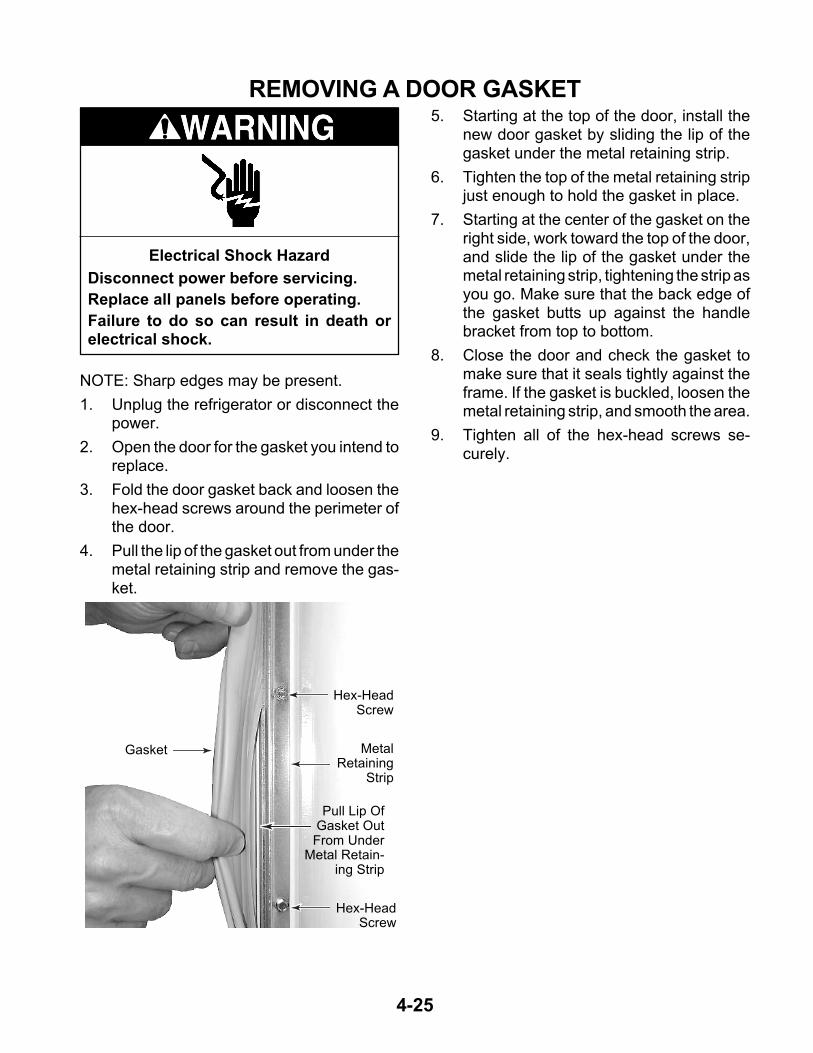
Pull Lip OfGasket OutFrom Under
Metal Retain-ing Strip
MetalRetaining
Strip
Gasket
NOTE: Sharp edges may be present.
1. Unplug the refrigerator or disconnect thepower.
2. Open the door for the gasket you intend toreplace.
3. Fold the door gasket back and loosen thehex-head screws around the perimeter ofthe door.
4. Pull the lip of the gasket out from under themetal retaining strip and remove the gas-ket.
Hex-HeadScrew
Hex-HeadScrew

4-26
REMOVING THE FREEZER OR REFRIGERATOR DOOR
NOTE: Sharp edges may be present.
1. Unplug the refrigerator or disconnect thepower.
2. Remove the main and louvered decora-tive panels (see page 4-2).
NOTE: If the freezer door has a water and icedispenser, it will be necessary to remove therefrigerator from its mounting location in orderto disconnect the wiring harness. To do this,perform step 3. If the freezer door does nothave a water and ice dispenser, skip step 3,and proceed to step 4, on page 4-28.
3. To remove a freezer door with a water &ice dispenser:
a) Remove the two screws from the basegrille and remove the grille.
Electrical Shock Hazard
Disconnect power before servicing.
Replace all panels before operating.
Failure to do so can result in death orelectrical shock.
Base GrilleScrew Screw
Tip Over Hazard
Refrigerator is top heavy and tips easilywhen not completely installed.
Keep door taped closed until refrigeratoris completely installed.
Use two or more people to move andinstall refrigerator.
Failure to do so can result in death orserious injury.
c) Pull the refrigerator out of its mountinglocation.
b) Use the leveling screws and lower therefrigerator onto the four rollers.
Leveling ScrewsRear Front

4-27
h) Remove the hex-head screw from thegreen ground wire on the water & icedispenser wiring harness.
d) Disconnect the water & ice dispenserelectrical harness connector at the backof the refrigerator.
Water & Ice Dispenser Electrical Harness Connector
Door Channel
Clip
f) Position a container to catch the waterin the next step.
e) Use a putty knife, slide the retainer clipsoff the door channel, and pull the wiringand water line out from under the chan-nel.
g) Disconnect the water reservoir tubingnut at the union and remove the nutfrom the end of the tubing.
Water & Ice Dispenser Electrical Harness
Water ReservoirUnion Nut
Harness Ground
Continued on the next page.
Electrical Shock Hazard
Connect green ground wire to groundscrew.
Failure to do so can result in death orelectrical shock.

4-28
NOTE: The door spring will remain under slighttension when the door is closed.
6. Use a pair of pliers and lift the end of thelinkage off the square post.
4. Remove the door switch & bracket for therefrigerator or freezer door (see page 4-4for the procedure).
5. With the door closed, remove the hex-head screw from the door linkage at thetop of the door.
Door Linkage Screw
7. Place a support under the door that youare removing to prevent it from falling.
8. Remove the four hex-head screws fromthe door hinge.
Lift DoorLinkage Off Post
Disconnect EndOf Spring
9. Grasp the door firmly and lift it off thebottom hinge pin.
Door HingeScrew(1 of 4)

5-1
COMPONENT TESTINGBefore testing any of the components, performthe following checks:
• The most common cause for control failure iscorrosion on connectors. Therefore, discon-necting and reconnecting wires will be nec-essary throughout test procedures.
Refer to page 4-18 for the procedure for servic-ing a thermistor.
1. Run the diagnostics tests (see page 6-1)and test the thermistors in steps 01 and02.
NOTE: For accurate temperature/resistancereadings, continue with the remaining steps tocheck the resistance of the thermistor(s).
2. Unplug the refrigerator or disconnect thepower.
3. Disconnect the thermistor wire connectorfrom the main harness.
4. Set the ohmmeter to the R x 1K scale.
5. Insert the test probes into the two connec-tor pins of the thermistor connector.
THERMISTOR
NOTE: If the resistance of the thermistor(s)was normal, perform the following voltage test.
1. Set the voltmeter to read a maximumvoltage of 10 volts DC.
2. Connect power to the refrigerator andallow it to enter the “cooling” mode.
3. With the thermistor disconnected and therefrigerator in the cooling mode, touch thevoltmeter test probes to the thermistormain harness connector pins. The metershould indicate approximately 5 volts DC.
If the voltage was not present, check for athermistor output at the main control board(see page 5-5).
6. Depending on the temperature, the metershould indicate within the approximaterange, as shown in the chart below.
• Check all connections before replacing com-ponents, looking for broken or loose wires,failed terminals, or wires not pressed intoconnectors far enough.
• Resistance checks must be made with powercord unplugged from outlet, and with wiringharness or connectors disconnected.
Electrical Shock Hazard
Disconnect power before servicing.Replace all panels before operating.Failure to do so can result in death or electrical shock.
TEMPERATURE RESISTANCE TEMPERATURE RESISTANCE(°°°° F) OHMS (APPROX.) (°°°° F) OHMS (APPROX.)
–5 25900-27500 4 5 5930-63000 22100-23500 50 5190-55105 18900-20000 55 4550-483010 16200-17200 60 4000-424015 13900-14800 65 3520-373020 12000-12800 70 3100-330025 10400-11000 75 2740-291030 8990-9550 80 2430-258032 8750 85 2160-229035 7800-8290 90 1920-20304 0 6800-7220
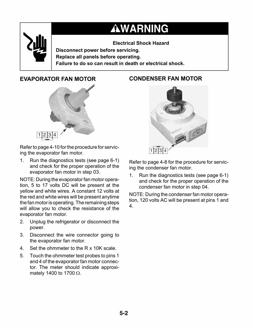
5-2
Electrical Shock Hazard
Disconnect power before servicing.Replace all panels before operating.Failure to do so can result in death or electrical shock.
CONDENSER FAN MOTOR
Refer to page 4-8 for the procedure for servic-ing the condenser fan motor.
1. Run the diagnostics tests (see page 6-1)and check for the proper operation of thecondenser fan motor in step 04.
NOTE: During the condenser fan motor opera-tion, 120 volts AC will be present at pins 1 and4.
1 2 3 4
EVAPORATOR FAN MOTOR
Refer to page 4-10 for the procedure for servic-ing the evaporator fan motor.
1. Run the diagnostics tests (see page 6-1)and check for the proper operation of theevaporator fan motor in step 03.
NOTE: During the evaporator fan motor opera-tion, 5 to 17 volts DC will be present at theyellow and white wires. A constant 12 volts atthe red and white wires will be present anytimethe fan motor is operating. The remaining stepswill allow you to check the resistance of theevaporator fan motor.
2. Unplug the refrigerator or disconnect thepower.
3. Disconnect the wire connector going tothe evaporator fan motor.
4. Set the ohmmeter to the R x 10K scale.
5. Touch the ohmmeter test probes to pins 1and 4 of the evaporator fan motor connec-tor. The meter should indicate approxi-mately 1400 to 1700 Ω.
1 2 3 4

5-3
COMPRESSOR & INVERTER
Refer to pages 4-4 and 4-9 for the proceduresfor servicing the inverter and compressor.
1. Run the diagnostics tests (see page 6-1)and check for the proper operation of thecompressor in step 05.
NOTE: If the compressor does not operateperform the following steps.
2. Connect power to the refrigerator andallow it to enter the “cooling” mode.
3. While the refrigerator is in the coolingmode, the inverter and main control boardvoltages should be as shown in the chartbelow.
4. Set the voltmeter to read the voltagesshown in the chart.
• If the 3 to 6 volts DC is not present atthe inverter red/white and red wires,check P7-3 and P7-8 on the main con-trol board for 3 to 6 volts DC. If the volt-age is not present, replace the maincontrol board.
Pins
Electrical Shock Hazard
Disconnect power before servicing.Replace all panels before operating.Failure to do so can result in death or electrical shock.
• If the 3 to 6 volts DC is present at themain control board, continue with step 5.
5. Unplug the refrigerator or disconnect thepower.
6. Disconnect the wire connector going tothe compressor.
7. Set the ohmmeter to the R x 1 scale.
8. Touch the meter leads to any two pins.The meter should indicate approximately9 to 10 Ω. Check between each set of pinsto test all three windings.
9. Set the ohmmeter to the highest scale.
10. Touch one meter lead to the cabinet groundand the other lead to each of the threecompressor terminals. The meter shouldindicate an open circuit (infinite).
COMPONENT INPUT/ OUTPUT LOCATIONS VOLTAGES
Red/White & Red Wires 3 To 6 Volts DCBlack & White Wires 120 Volts AC
Main Control Board P7-3 (Red) & P7-8 (Red/White) 3 To 6 Volts DC
Inverter
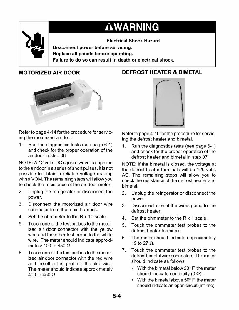
5-4
Electrical Shock Hazard
Disconnect power before servicing.Replace all panels before operating.Failure to do so can result in death or electrical shock.
MOTORIZED AIR DOOR
Refer to page 4-14 for the procedure for servic-ing the motorized air door.
1. Run the diagnostics tests (see page 6-1)and check for the proper operation of theair door in step 06.
NOTE: A 12 volts DC square wave is suppliedto the air door in a series of short pulses. It is notpossible to obtain a reliable voltage readingwith a VOM. The remaining steps will allow youto check the resistance of the air door motor.
2. Unplug the refrigerator or disconnect thepower.
3. Disconnect the motorized air door wireconnector from the main harness.
4. Set the ohmmeter to the R x 10 scale.
5. Touch one of the test probes to the motor-ized air door connector with the yellowwire and the other test probe to the whitewire. The meter should indicate approxi-mately 400 to 450 Ω.
6. Touch one of the test probes to the motor-ized air door connector with the red wireand the other test probe to the blue wire.The meter should indicate approximately400 to 450 Ω.
DEFROST HEATER & BIMETAL
Refer to page 4-10 for the procedure for servic-ing the defrost heater and bimetal.
1. Run the diagnostics tests (see page 6-1)and check for the proper operation of thedefrost heater and bimetal in step 07.
NOTE: If the bimetal is closed, the voltage atthe defrost heater terminals will be 120 voltsAC. The remaining steps will allow you tocheck the resistance of the defrost heater andbimetal.
2. Unplug the refrigerator or disconnect thepower.
3. Disconnect one of the wires going to thedefrost heater.
4. Set the ohmmeter to the R x 1 scale.
5. Touch the ohmmeter test probes to thedefrost heater terminals.
6. The meter should indicate approximately19 to 27 Ω.
7. Touch the ohmmeter test probes to thedefrost bimetal wire connectors. The metershould indicate as follows:
• With the bimetal below 20° F, the metershould indicate continuity (0 Ω).
• With the bimetal above 50° F, the metershould indicate an open circuit (infinite).

5-5
Electrical Shock Hazard
Disconnect power before servicing.Replace all panels before operating.Failure to do so can result in death or electrical shock.
MAIN CONTROL BOARD
INPUTSP4
THERMISTORSP3
DISPLAY BOARDP2120 VAC SUPPLY
P5
P7OUTPUTS
P6OUTPUTS
11
2 1 23 1 2 34
3 45 6 7 8
2 3 4 5
12345
12345
10 9 8 7 6
Refer to page 4-4 for the procedure for servicing the main control board.
NOTE: See the chart for the main control board test specifications.
PLUG PIN # DESCRIPTION OUTPUT CONDITION1 Communication Line N / A2 Display Voltage 12 VDC Measured at pins 2 & 33 GND GND1 Ref. Thermistor GND2 Frz. Thermistor GND3 Ref. Thermistor Output 5 VDC Measured at pins 1 & 34 Frz. Thermistor Output 5 VDC Measured at pins 2 & 41 Ref. Door Sw Enable 120 VAC2 Frz. Door Sw Enable 120 VAC3 N / A
4 Ref. Door Input 120 VAC Voltage present when door is open
5 Ice Maker Valve Input 120 VAC Voltage present when ice maker is energized
6 Dispenser Valve Input 120 VAC Voltage present when dispenser valve is energized
7 Bimetal Input 120 VAC Voltage present when bimetal is closed
8 Frz. Door Input 120 VAC1 AC GND AC GND2 AC L1 120 VAC3 AC Neutral AC Neutral4 AC Neutral AC Neutral5 AC L1 120 VAC
1 Condenser Fan 120 VAC Voltage present when condenser fan is on
2 N / A3 N / A
4 Defrost Heater 120 VAC Voltage present when defrost heater is on
5 Ice Maker Enable 120 VACVoltage present when I/M bail arm is down & I/M is active
1 Air Door2 Air Door3 Compressor Drive 3 - 6 VDC Measured at pins 3 & 84 Evap. Fan Feedback N / A5 Evap. Fan Constant 12 VDC Measured at pins 5 & 96 Air Door7 Air Door8 Compressor Drive 3 - 6 VDC Measured at pins 3 & 89 Evap. Fan Ground Evap. GND10 Evap. Fan Run Voltage 5 - 12 VDC Measured at pins 9 & 10
P6
P7
P2
P3
P 4
P5

5-6
Electrical Shock Hazard
Disconnect power before servicing.Replace all panels before operating.Failure to do so can result in death or electrical shock.
Refer to page 4-16 for the procedure for servic-ing the crush/cube solenoid.
1. Unplug the refrigerator or disconnect thepower.
2. Disconnect one of the wires going to thesolenoid.
3. Set the ohmmeter to the R x 1 scale.
4. Touch the ohmmeter test probes to thesolenoid terminals.
5. The meter should indicate approximately35 to 45 ohms.
CRUSH/CUBE SOLENOID ICE MAKER AUGER MOTOR
Refer to page 4-16 for the procedure for servic-ing the ice maker auger motor.
1. Unplug the refrigerator or disconnect thepower.
2. Disconnect one of the wires going to theauger motor.
3. Set the ohmmeter to the R x 1 scale.
4. Touch the ohmmeter test probes to theauger motor terminals.
5. The meter should indicate approximately2 to 4 ohms.

5-7
Electrical Shock Hazard
Disconnect power before servicing.Replace all panels before operating.Failure to do so can result in death or electrical shock.
DOOR SWITCH
Refer to page 4-4 for the procedure for servic-ing a door switch.
1. Unplug the refrigerator or disconnect thepower.
2. Disconnect one of the wires going to thedoor switch.
3. Set the ohmmeter to the R x 1 scale.
4. Touch the ohmmeter test probes to theN.O. and COM door switch terminals.
5. The meter should indicate an open circuit(infinite).
6. Press the door switch actuator button andthe meter should indicate continuity (0 Ω).
7. Touch the ohmmeter test probes to theN.C. and COM door switch terminals.
8. The meter should indicate continuity (0 Ω).NOTE: The door switches are normally-closed.
9. Press the door switch actuator button andthe meter should indicate an open circuit(infinite).
WATER VALVE SOLENOID
Refer to page 4-22 for the procedure for servic-ing the water valve.
1. Unplug the refrigerator or disconnect thepower.
2. Disconnect the wire connectors from thewater valve solenoid terminals.
3. Set the ohmmeter to the R x 1 scale.
4. Touch the ohmmeter test probes to theterminals of the ice maker solenoid. Theohmmeter should indicate approximately160 to 170 Ω.
5. Touch the ohmmeter test probes to theterminals of the water dispenser solenoid.The ohmmeter should indicate approxi-mately 330 to 355 Ω.
Ice Maker Solenoid (1/4″ Outlet)
Water Dispenser Solenoid (5/16″ Outlet)

5-8
— NOTES —

6-1
DIAGNOSIS & TROUBLESHOOTINGDIAGNOSIS
PRE-DIAGNOSTICS CHECKS• Confirm the refrigerator and freezer tem-
peratures before beginning other checks.
• See if the compressor, evaporator, andcondenser fans are running.
• Check the position of the air door.
DIAGNOSTICS MODEThe Diagnostics Mode is used to:
• Check the refrigerator & freezer ther-mistors.
• Operate the evaporator fan motor at 3000rpm.
• Operate the condenser fan motor and com-pressor.
• Check the defrost bimetal and heater.
To enter the Diagnostics Mode, the controlmust be turned on, and be in a normal coolingmode.
PowerOn/Off
Warmer
Colder
Warmer
Colder
FREEZER REFRIGERATORWATER FILTER
PERCENT LEFT
RESET°C
SELECT
Both the Power On/Off and the Water FilterReset keys must be functional. The refrigera-tor display shows the step number. The resultsof the checks are displayed on the water filterstatus indicator. After 20 minutes, the controlwill default from the Diagnostics Mode to anormal cooling mode.
To enter the diagnostics mode:
• Press and hold the Water Filter Resetkeypad, and then immediately press andhold the Power keypad. Continue to pressboth keypads for 3 seconds, or until youhear a beep.
To advance the diagnostics sequence:
• To advance to the next step in the se-quence, press and hold the Water FilterReset key for 2 seconds, or until you heara beep. The Diagnostics Chart on the nextpage shows the step number and the com-ponent being tested in each step.

6-2
WATER FILTER INPUT (WFI) TESTTo confirm that the water valves are beingmonitored by the WFI control, follow the pro-cedures listed:
Testing The Dispenser Valve Input
1. Open the refrigerator door.
2. Depress the refrigerator light switch.
3. Place a container under the water spout.
4. Activate the water dispenser.
5. Read the WFI display. “00” indicates anormal input.
Testing The Ice maker Valve Input
1. Open the refrigerator door.
2. Depress the refrigerator light switch.
3. Activate the ice maker and wait for a waterfill.
4. Read the WFI display during the fill. “99”indicates a normal input.
DIAGNOSTICS CHART
Step Component Tested Result* Comment 01 Thermistor is within normal range.02 Thermistor is open or less than –20°F.03 Thermistor is shorted or greater than 115°F.01 Thermistor is within normal range.02 Thermistor is open or less than 10°F.03 Thermistor is shorted or greater than 115°F.01 Evaporator Fan Motor is On at correct speed.02 Evaporator Fan Motor is On at incorrect speed.
0 4 Condenser Fan Motor 01 Condenser Fan Motor is On.01 Compressor is On at 4500 rpm.02 Compressor is Off waiting for minimum (7 minute) Off delay.
06 Air Door 01 Air Door fully opens. **
01 Defrost Heater is energized, bimetal closed.
02 Bimetal open. †
FreezerThermistor01
Refrigerator Thermistor02
† The bimetal may be bypassed with an insulated jumper.
03
05 Compressor
** The air door will close at step 01, and reset to the correct opening after exiting diagnostics.
Press the “Water Filter Reset” to exit diagnostics. * Shown on the Water Filter Indicator display.
07 Bimetal/Defrost Heater
Evaporator Fan Motor

6-3
TROUBLESHOOTING CHARTPROBLEM POSSIBLE CAUSE TEST PROCEDURE-ACTION
No DC control voltage from main PCB to the inverter board.
See "Component Testing" section for main PCB test procedure.
Control voltage wires loose or reversed.
Check connections and repair as needed.
Compressor. See "Component Testing" section for compressor/inverter test procedure.Inverter board. See "Component Testing" section for compressor/inverter test procedure.
Refrigerator control set too warm.
Set to a lower temperature.
Refrigerator thermistor. Check wires and connectors. Run diagnostics and if a defective thermistor is indicated, confirm with ohms test. See "Component Testing".
Air door stuck closed or inoperative.
Look for ice or other blockage in air door. Run diagnostics test to operate air door.
Evaporator fan motor not running.
Run diagnostics test to operate the evaporator fan motor. Check for a blocked fan blade and repair as necessary. Check for 5-17vdc from pin P7-9 to P7-10. If voltage is correct, replace the motor.
Blocked air flow. Check air door outlet and air returns for blockage.Warm freezer compartment. See "Freezer compartment too warm."
Refrigerator control set too cold. Set to a higher temperature.
Refrigerator thermistor. Check wires and connectors. Run diagnostics and if a defective thermistor is indicated, confirm with ohms test. See "Component Testing".
Air door stuck open or inoperative.
Look for ice or other blockage in air door. Run diagnostics test to operate air door. Check for proper DC input voltage. If voltage is normal and door will still not operate, replace air door.
Air door seal missing or damaged. Repair or replace seal.Main PC board. Run diagnostics test to operate air door.
Freezer control set too warm. Set to a lower temperature.
Freezer thermistor. Check wires and connectors. Run diagnostics and if a defective thermistor is indicated, confirm with ohms test. See "Component Testing".
Evaporator fan motor not running.
Run diagnostics test to operate the evaporator fan motor. Check for a blocked fan blade and repair as necessary. Check for 5-17vdc from pin P7-9 to P7-10. If voltage is correct, replace the motor.
Condenser fan motor not running. Check for a blocked fan blade and repair as necessary. See "Component Testing" section for condenser fan motor test procedure.
Frost blocking evaporator. Run diagnostics test to operate defrost system. Test defrost heater and bi-metal.
Freezer control set too cold. Set to a higher temperature.
Refrigerator operating in the Max Cool or Automatic Max Ice Mode (see page 3-5).
Normal operation.
Freezer thermistor. Check wires and connectors. Run diagnostics and if a defective thermistor is indicated, confirm with ohms test. See "Component Testing".
No evaporator fan motor feedback.
The fan motor will run at 3000 rpm.
Main control board is over temperature.
Look for blocked condenser air flow or inoperative condenser fan motor.
Refrigerator over 48°F or freezer over 15°F for 3 hours.
Run diagnostics and test operation of all components.
Both thermistors failed. Run diagnostics and test thermistors and thermistor leads.No feedback from evaporator fan motor.
Run diagnostics and test fan motor and/or wiring.
Refrigerator runs too long. Normal.
It is designed for this refrigerator to run almost constantly at the lowest possible compressor speed. Starting and stopping the compressor uses more power than continuous low rpm operation. Instruct customer.
Unit is set for Holiday Mode. Press the Holiday Mode key to cancel operation.
Either door open for over 10 minutes.
Close door and/or check door switches.
No temperature display, no interior lights.
"Call Service" icon lights and/or alarm is activated.
Condenser fan runs but the compressor
will not start.
Freezer compartment
too warm.
Freezer compartment
too cold.
Refrigerator compartment
too cold.
Refrigerator compartment
too warm.

6-4
— NOTES —
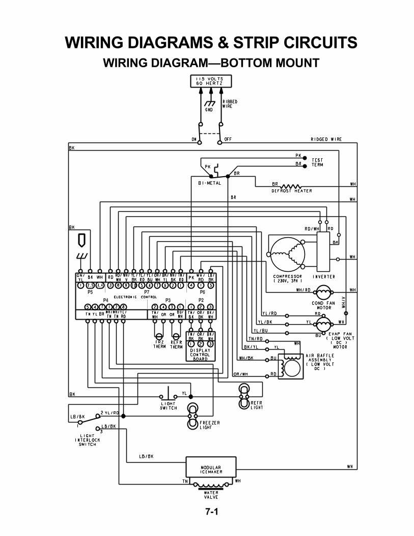
7-1
WIRING DIAGRAMS & STRIP CIRCUITSWIRING DIAGRAM—BOTTOM MOUNT
P5 P7 P6
P2P3P4

7-2
WIRING DIAGRAM—SIDE-BY-SIDE MODELS
P5 P7 P6P2P3P4
OPTIONAL -DISPENSER MODELS ONLY

7-3
STRIP CIRCUITSCOOLING CIRCUITSCOMPRESSOR
POWERON/OFF
POWERON/OFF
WH
RD
RD/WHBK
COMPRESSOR
L1 N
P7-3P7-8
P5-2 P5-3
INVERTERBOARD
ELECTRONICCONTROL
BOARD
THERMISTOR
CONDENSER FAN MOTOR
POWERON/OFF
POWERON/OFF
BK WH/RD WHL1 N
P5-2 P6-1ELECTRONICCONTROL
BOARD
CONDENSERFAN MOTOR

7-4
EVAPORATOR FAN MOTOR
POWERON/OFF
POWERON/OFF
BK WHL1 N
P5-2 P5-3
P7-4 P7-5 P7-9 P7-10
ELECTRONIC CONTROLBOARD
WH
EVAPORATORFAN MOTOR
YL
RD
BU
YL/BU WH/VT YL/BKYL/RD
DEFROST CYCLEDEFROST HEATER
POWERON/OFF
POWERON/OFF
BK
DEFROSTHEATER
L1 NP5-2 P6-4 PKELECTRONIC
CONTROLBOARD
BIMETAL
POWERON/OFF
POWERON/OFF
BKL1 N
P5-2 P6-5 LB/BK WHELECTRONICCONTROL
BOARD
ICE MAKERMODULE
ELECTRONIC CONTROL ENABLED CIRCUITSICE MAKER

7-5
POWERON/OFF
POWERON/OFF
BKL1 N
P4-1WH/TNDOOR SWITCH
ELECTRONICCONTROL
BOARD
POWERON/OFF
POWERON/OFF
BKL1 N
P4-2WH/TN
DOOR SWITCH
ELECTRONICCONTROL
BOARD1 2
3
REFRIGERATOR LIGHT
FREEZER LIGHT

7-6
— NOTES —

7-7
— NOTES —

7-8
— NOTES —

PRODUCT SPECIFICATIONS
AND
WARRANTY INFORMATION SOURCES
IN THE UNITED STATES:
FOR PRODUCT SPECIFICATIONS AND WARRANTY INFORMATION CALL:
FOR TECHNICAL ASSISTANCE WHILE AT THE CUSTOMER’S HOME CALL:
THE TECHNICAL ASSISTANCE LINE: 1-800-253-2870
HAVE YOUR STORE NUMBER READY TO IDENTIFY YOU AS AN
AUTHORIZED SERVICER
FOR LITERATURE ORDERS:
PHONE: 1-800-851-4605
IN CANADA:
FOR PRODUCT SPECIFICATIONS AND WARRANTY INFORMATION CALL:
1-800-461-5681
FOR TECHNICAL ASSISTANCE WHILE AT THE CUSTOMER’S HOME CALL:
THE TECHNICAL ASSISTANCE LINE: 1-800-488-4791
HAVE YOUR STORE NUMBER READY TO IDENTIFY YOU AS AN
AUTHORIZED SERVICER
FOR WHIRLPOOL PRODUCTS: 1-800-253-1301
FOR KITCHENAID PRODUCTS: 1-800-422-1230
FOR ROPER PRODUCTS: 1-800-447-6737