STUDY OF SOLAR AND TROMBE WALLS IN A MEDITERRANEAN CLIMATE ... · PDF fileSTUDY OF SOLAR AND...
16
Congresso de Métodos Numéricos em Engenharia 2015 Lisboa, 29 de Junho a 2 de Julho, 2015 © APMTAC, Portugal, 2015 STUDY OF SOLAR AND TROMBE WALLS IN A MEDITERRANEAN CLIMATE, INSTALLED IN RESIDENTIAL BUILDINGS Nuno Simões 1,2 *, Inês Simões 1,2 and Mário Manaia 2 1: ITeCons Rua Pedro Hispano, s/n; 3030-289 Coimbra; Portugal e-mail: {mivsimoes, nasimoes, tadeu}@itecons.uc.pt, web: http://www.itecons.uc.pt.pt 2: Department of Civil Engineering University of Coimbra Rua Luís Reis Santos - Pólo II; 3030-788 Coimbra; Portugal Keywords: Trombe wall, solar wall, Mediterranean climate, dynamic simulation Abstract The reduction of energy consumption and the use of energy from renewable sources in the buildings sector, which accounts for 40 % of total energy consumption in the EU, are important measures to reduce energy dependency and greenhouse gas emissions. Therefore, energy efficiency improvement measures should be taken in both new and existing buildings. One option is to develop and install building systems and solutions that are more sustainable, such as passive solar systems. Only a few studies have looked at the behaviour of ventilated solar walls (known as Trombe walls) in temperate climates. This study therefore sets out to assess how a Mediterranean climate would affect the performance of this system, particularly during the summer. This study assesses the dynamic energy performance, i.e. how the ventilated solar walls influence the reduction of energy consumption in buildings. The methodology involved the following steps: definition and characterization of a reference room representing a “living room”, as is typically found in residential housing buildings; selection of geographical locations to represent the local microclimate range over the general Mediterranean climate region; definition of a solar wall (SW) and a Trombe wall (TW) system (composition, thermal properties, geometrical and functional characterization), and the dynamic simulation of all scenarios, based on EnergyPlus. The energy benefits of solar walls for all the scenarios are then discussed.
Transcript of STUDY OF SOLAR AND TROMBE WALLS IN A MEDITERRANEAN CLIMATE ... · PDF fileSTUDY OF SOLAR AND...

Congresso de Métodos Numéricos em Engenharia 2015 Lisboa, 29 de Junho a 2 de Julho, 2015
© APMTAC, Portugal, 2015 STUDY OF SOLAR AND TROMBE WALLS IN A MEDITERRANEAN
CLIMATE, INSTALLED IN RESIDENTIAL BUILDINGS
Nuno Simões1,2*, Inês Simões1,2 and Mário Manaia2
1: ITeCons Rua Pedro Hispano, s/n; 3030-289 Coimbra; Portugal
e-mail: {mivsimoes, nasimoes, tadeu}@itecons.uc.pt, web: http://www.itecons.uc.pt.pt
2: Department of Civil Engineering University of Coimbra
Rua Luís Reis Santos - Pólo II; 3030-788 Coimbra; Portugal
Keywords: Trombe wall, solar wall, Mediterranean climate, dynamic simulation
Abstract The reduction of energy consumption and the use of energy from renewable sources in the buildings sector, which accounts for 40 % of total energy consumption in the EU, are important measures to reduce energy dependency and greenhouse gas emissions. Therefore, energy efficiency improvement measures should be taken in both new and existing buildings. One option is to develop and install building systems and solutions that are more sustainable, such as passive solar systems.
Only a few studies have looked at the behaviour of ventilated solar walls (known as Trombe walls) in temperate climates. This study therefore sets out to assess how a Mediterranean climate would affect the performance of this system, particularly during the summer. This study assesses the dynamic energy performance, i.e. how the ventilated solar walls influence the reduction of energy consumption in buildings.
The methodology involved the following steps: definition and characterization of a reference room representing a “living room”, as is typically found in residential housing buildings; selection of geographical locations to represent the local microclimate range over the general Mediterranean climate region; definition of a solar wall (SW) and a Trombe wall (TW) system (composition, thermal properties, geometrical and functional characterization), and the dynamic simulation of all scenarios, based on EnergyPlus. The energy benefits of solar walls for all the scenarios are then discussed.
Nuno A. Simões1,2*, Inês Simões1,2 and Mário M. Manaia2
2
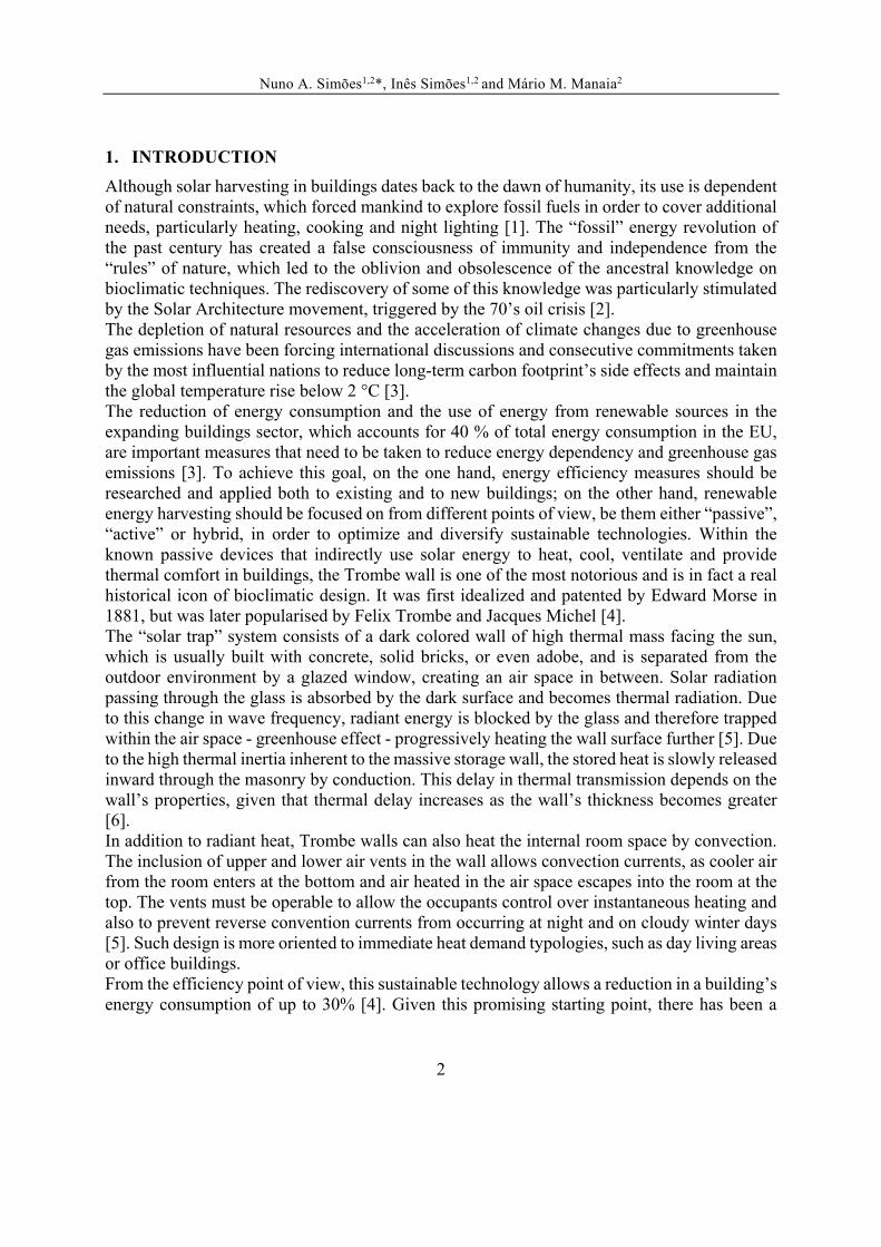
1. INTRODUCTION
Although solar harvesting in buildings dates back to the dawn of humanity, its use is dependent of natural constraints, which forced mankind to explore fossil fuels in order to cover additional needs, particularly heating, cooking and night lighting [1]. The “fossil” energy revolution of the past century has created a false consciousness of immunity and independence from the “rules” of nature, which led to the oblivion and obsolescence of the ancestral knowledge on bioclimatic techniques. The rediscovery of some of this knowledge was particularly stimulated by the Solar Architecture movement, triggered by the 70’s oil crisis [2]. The depletion of natural resources and the acceleration of climate changes due to greenhouse gas emissions have been forcing international discussions and consecutive commitments taken by the most influential nations to reduce long-term carbon footprint’s side effects and maintain the global temperature rise below 2 °C [3]. The reduction of energy consumption and the use of energy from renewable sources in the expanding buildings sector, which accounts for 40 % of total energy consumption in the EU, are important measures that need to be taken to reduce energy dependency and greenhouse gas emissions [3]. To achieve this goal, on the one hand, energy efficiency measures should be researched and applied both to existing and to new buildings; on the other hand, renewable energy harvesting should be focused on from different points of view, be them either “passive”, “active” or hybrid, in order to optimize and diversify sustainable technologies. Within the known passive devices that indirectly use solar energy to heat, cool, ventilate and provide thermal comfort in buildings, the Trombe wall is one of the most notorious and is in fact a real historical icon of bioclimatic design. It was first idealized and patented by Edward Morse in 1881, but was later popularised by Felix Trombe and Jacques Michel [4]. The “solar trap” system consists of a dark colored wall of high thermal mass facing the sun, which is usually built with concrete, solid bricks, or even adobe, and is separated from the outdoor environment by a glazed window, creating an air space in between. Solar radiation passing through the glass is absorbed by the dark surface and becomes thermal radiation. Due to this change in wave frequency, radiant energy is blocked by the glass and therefore trapped within the air space - greenhouse effect - progressively heating the wall surface further [5]. Due to the high thermal inertia inherent to the massive storage wall, the stored heat is slowly released inward through the masonry by conduction. This delay in thermal transmission depends on the wall’s properties, given that thermal delay increases as the wall’s thickness becomes greater [6]. In addition to radiant heat, Trombe walls can also heat the internal room space by convection. The inclusion of upper and lower air vents in the wall allows convection currents, as cooler air from the room enters at the bottom and air heated in the air space escapes into the room at the top. The vents must be operable to allow the occupants control over instantaneous heating and also to prevent reverse convention currents from occurring at night and on cloudy winter days [5]. Such design is more oriented to immediate heat demand typologies, such as day living areas or office buildings. From the efficiency point of view, this sustainable technology allows a reduction in a building’s energy consumption of up to 30% [4]. Given this promising starting point, there has been a

Nuno A. Simões1,2*, Inês Simões1,2 and Mário M. Manaia2
3
recent and massive interest in this particular issue, enhanced by the crescent powerful software tools available, which are capable of accurately simulating, evaluating and optimizing these devices within buildings. Therefore, several studies have emerged ([4], [6]–[12]) focusing on different Trombe walls configurations, comparing different components, sizing, materials, and evaluating the system’s implementation in different buildings and geographical locations, among a plethora of approaches and objectives outlined. However, as most of the research work focuses on the optimization of winter energy performance, since this system was originally conceived for passive heating of buildings, few studies focus on summer behaviour, indoor thermal comfort conditions and life cycle analysis [12]. There are still uncertainties about their real performance, especially in summer, when the system is most vulnerable to the known overheating phenomenon. Most studies on the system’s behaviour during the cooling season only give recommendations and rarely quantify the energy performance of different solutions [12]. Therefore, this study sets out to assess the performance of this system when implemented in several regions with Mediterranean climate, particularly in summer, and how it influences the overall reduction of energy consumption in buildings. Numerical simulations in dynamic state were performed using EnergyPlus software, under similar conditions, for three models: control reference room, reference room with a solar wall (SW) and a reference room with a Trombe wall (TW). The study is developed in three phases, from particular to general. The first step, based on the climate conditions in Évora (Portugal), focuses on comparatively evaluating the influence of internal thermal mass variation on the behaviour of each reference room during typical winter and summer weeks, meant to represent the most extreme climatic conditions. The second step focuses on comparatively evaluating the influence of different shading devices – exterior overhang vs venetian blind - on each reference room’s behaviour during the whole cooling season. The last step expands the domain of the study to different locations around the Mediterranean basin, in order to comparatively evaluate the influence of each passive device on the heating and cooling energy demand.
2. DEFINITION OF CASE STUDY
The methodology involved the following steps: definition and characterization of a reference room representing a “living room” typically found in residential buildings; selection of geographical locations to represent the local microclimate range over the general Mediterranean climate region; definition of a ventilated solar wall system (composition, thermal properties, geometrical and functional characterization), and the detailed dynamic simulation of all scenarios, based on EnergyPlus data and calculations.
2.1. Reference room definition and characterization
The compartment which was used as a reference is based on the one proposed by the ISO 13791 [13] and EN 15265 [14], which establish the general criteria and validation processes of the energy performance of buildings. The internal dimensions of the room are 3,6x5,5x2,8 m. The external wall, including window glazing and the SW or TW modules when available, faces

Nuno A. Simões1,2*, Inês Simões1,2 and Mário M. Manaia2
4
south and has 3,6 m length. The remaining walls, along with the ceiling and floor (interior mass), were considered adiabatic. Based on Veríssimo’s research [15] on the most common dimensions and proportions of windows in Portuguese building façades after 1960s’, the selected window is 1,50 m length, 1,1 m height and is placed on the south wall, 0,9 m away from the floor. This leads to a window/floor ratio of 8,33%, and a window/façade ratio of 16,37%. The areas of the components of the reference room are given in Table 1.
External wall
Window Glazing
Internal wall left
Internal wall right
Internal wall back
Floor Ceiling
Area (m²) 8,43 1,65 15,4 15,4 10,08 19,8 19,8
Table 1: Areas of the components of the reference room.
As an example, the 3D model (Designbuilder) of the Trombe wall case with overhang used in dynamic simulation calculations is shown in Figure 1.
a) b
Figure 1: Scheme of the geometry of the TW case model with overhang, using the Designbuilder software: a) exterior views; b) interior view.
The thermophysical properties of the component layers of the construction, for both opaque and glazing elements, used in the case study simulations are listed in Tables 2 and 3.
Type Constructive element S
[m] λ
[W/(m.K)]ρ
[kg/m3] Cp
[J/(kg.K)] R
[m²K/W] U
[W/m2.K]
External Wall (High Thermal
Inertia)
CIBSE Guide A (2006) External plaster 0,02 0,72 1680 840
1,1 EN 1745 Hollow Clay Brick 0,11 0,43 1000 850 0,27 ISO 6946 Air gap >=25mm 0,03 0,18 EN 1745 Hollow Clay Brick 0,11 0,43 1000 850 0,27 EN 15265 Internal plastering 0,02 0,7 1400 850
External Wall (Reduced Thermal
Mass)
CIBSE Guide A (2006) External plaster 0,02 0,72 1680 840
0,51
EN 1745 Hollow Clay Brick 0,11 0,43 1000 850 0,27 ISO 6946 Air gap >=25mm 0,03 0,18 EN 1745 Hollow Clay Brick 0,11 0,43 1000 850 0,27 EN 15265 Internal plastering 0,02 0,7 1400 850 EN 15265 Mineral Wool Insulation 0,04 0,04 50 850 ISO 10456 Gypsum Plasterboard 0,01 0,25 900 1000
Internal Partition (High Thermal
Mass)
EN 15265 Internal Plastering 0,02 0,7 1400 850 1,73 EN 1745 Hollow Clay Brick 0,11 0,43 1000 850 0,27
EN 15265 Internal Plastering 0,02 0,7 1400 850 Internal Partition
(Low Thermal Mass)
ISO 10456 Gypsum Plasterboard 0,01 0,25 900 1000
0,35 EN 15265 Mineral Wool (low density) 0,1 0,04 30 850
ISO 10456 Gypsum Plasterboard 0,01 0,25 900 1000 EN 15265 Concrete 0,18 2,1 2400 850 0,74

Nuno A. Simões1,2*, Inês Simões1,2 and Mário M. Manaia2
5
EN 15265 Type 3f (floor/ceiling) (High
Thermal Mass)
EN 15265 Mineral Wool Insulation 0,04 0,04 50 850 EN 15265 Cement Floor 0,06 1,4 2000 850 EN 15265 Plastic Covering 0 0,23 1500 1500
EN 15265 Type 3f based
(floor/ceiling) (Reduced Thermal
Mass)
ISO 10456 Gypsum Plasterboard 0,01 0,25 900 1000
0,335
EN 15265 Mineral Wool (low density) 0,04 0,04 30 850 ISO 6946 Air gap 50mm (downwards) 0,05 0,21 EN 15265 Concrete 0,18 2,1 2400 850
EN 15265 Mineral Wool Insulation 0,04 0,04 50 850 EN 15265 Cement Floor 0,06 1,4 2000 850 EN 15265 Insulating Layer 0,01 0,04 30 850 CIBSE Guide A (2006) Timber Flooring 0,01 0,14 650 1200
Trombe wall 1 EN 1745 Brick Masonry 0,35 0,85 1700 850 1,489 Nomenclature: S - layer thickness; λ - thermal conductivity;
ρ - density; Cp - specific heat; R - thermal resistance; U - thermal transmission coefficient;
Table 2: Thermophysical properties of the component layers of the opaque building elements.
Glazing Constructive element Thickness
(mm)
Thermal Condutivity [W/(m.K)]
Solar Transmittance
Inside/Outside Reflectance
Inside/Outside Emissivity
U value (ISO 10292 /
EN 673)
Total Solar Transmission
(SHGC)
EN 15265 DP
Glazing
EN 15265 external surface glass
6,00 1,00 0,84 0,08 0,90
2,93 0,764 EN 15265 air cavity 13,60 0,025 EN 15265 internal surface glass
6,00 1,00 0,84 0,08 0,90
Table 3: Thermophysical properties of the component layers of the glazing.
2.2. Target locations and climate data
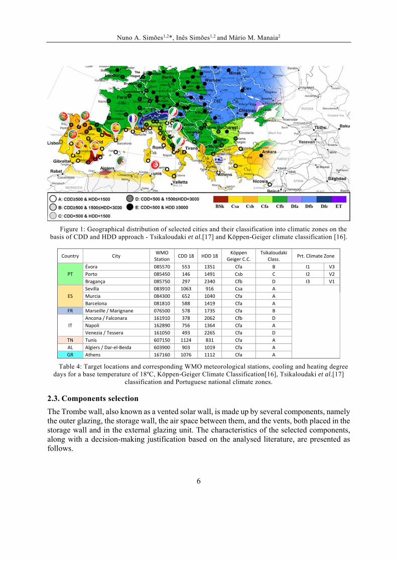
The comparative analysis of each model under different climate conditions compelled a selection of several target locations around the Mediterranean basin. The criteria was established on the basis of covering this geographical area, as well as covering the local microclimates range, according simultaneously to the updated Köppen-Geiger Climate Classification [16] and the Tsikaloudaki et al. climate classification proposal [17]. A set of 13 cities was selected and their individual climate data was considered in the dynamic simulations (Figure 1 and Table 4).
Nuno A. Simões1,2*, Inês Simões1,2 and Mário M. Manaia2
6
Figure 1: Geographical distribution of selected cities and their classification into climatic zones on the
basis of CDD and HDD approach - Tsikaloudaki et al.[17] and Köppen-Geiger climate classification [16].
Country City WMO Station
CDD 18 HDD 18 Köppen
Geiger C.C. Tsikaloudaki
Class. Prt. Climate Zone
PT
Évora 085570 553 1351 Cfa B I1 V3
Porto 085450 146 1491 Csb C I2 V2
Bragança 085750 297 2340 Cfb D I3 V1
ES
Sevilla 083910 1063 916 Csa A
Murcia 084300 652 1040 Cfa A
Barcelona 081810 588 1419 Cfa A
FR Marseille / Marignane 076500 578 1735 Cfa B
IT
Ancona / Falconara 161910 378 2062 Cfb D
Napoli 162890 756 1364 Cfa A
Venezia / Tessera 161050 493 2265 Cfa D
TN Tunis 607150 1124 831 Cfa A
AL Algiers / Dar‐el‐Beida 603900 903 1019 Cfa A
GR Athens 167160 1076 1112 Cfa A
Table 4: Target locations and corresponding WMO meteorological stations, cooling and heating degree days for a base temperature of 18ºC, Köppen-Geiger Climate Classification[16], Tsikaloudaki et al.[17]
classification and Portuguese national climate zones.
2.3. Components selection
The Trombe wall, also known as a vented solar wall, is made up by several components, namely the outer glazing, the storage wall, the air space between them, and the vents, both placed in the storage wall and in the external glazing unit. The characteristics of the selected components, along with a decision-making justification based on the analysed literature, are presented as follows.

Nuno A. Simões1,2*, Inês Simões1,2 and Mário M. Manaia2
7
Storage wall materiality and size
Several authors focus on the influence of width, area and materiality of the storage wall on the performance of ventilated Trombe walls ([4], [7], [18]). Based on the findings of these studies, the present study uses 35 cm for the storage wall’s thickness and solid brick as the main material.
Glazing
Thermal inertia of the storage wall mainly influences the thermal delay between gaining heat and releasing it. Additionally, in order to improve the thermal performance of the storage wall it is necessary to focus on a glazing system capable of enhancing the capture and conservation of heat within the air space during daytime, while simultaneously avoiding thermal loss to the exterior [7]. Considering several studies ([7], [10], [19], [20]), in particular those concerned with the overheating effects of the Trombe wall system located in Mediterranean climates, the use of conventional double glazing, rather than low-e double glazing, was assumed.
Absorber
The colour and the texture of the external surface of storage walls influence heat absorption capacity. Several studies have proven that highly absorptive coating materials improve the wall’s storage capacity and enhance the systems efficiency [4]. Moreover, the effects of the coating colour have been studied by Özbalta and Kartal [21] which concluded that the use of dark colors compared to light colors almost triples the annual thermal gains percentage, independently of the storage wall’s materials. Consequently, in the present study, the use of a selective surface coating (special black surface treatment) with the following thermophysical properties is assumed: absorptivity α=0,9; emissivity ε=0,15; reflectivity =0,2.
Air Space
Regarding the thickness of the air space, there are no consensual guidelines, nor methodologies to evaluate its sizing. For instance, according to Torcellini et al., the air space thickness should vary between 2 and 5 cm, while Mendonça proposes a variation between 5 and 20 cm, and Moita recommends a range from 10 and 15 cm [6]. Finally, in Liping and Angui’s parametric study of a Trombe wall [23] using the CFD Fluent software, it was concluded that the ideal air space thickness should correspond to 1/10 of its height, and, to reach the maximum ventilation rate, the air gap thickness should vary between 20 and 30 cm. Following this last study, an air space of 28 cm for a storage wall with 2,8 m height was considered in the present study.
Vents
Concerning the sizing of the vents, there are still few studies on this issue. Briga de Sá has advised a relation of 3/20 between the vents opening area and the height of the air gap [7]. In this work, two vents with the characteristics shown in Table 5 were defined.

Nuno A. Simões1,2*, Inês Simões1,2 and Mário M. Manaia2
8
Vents Function Schedule Type Height
(m) Lenght
(m)
Total Area (m2)
Vents/Wall ratio
Distance between vents (m)
Coefficient of discharge
Internal Heating Season
10:00 - 20:00
Grille, light stats
0,17 0,60 0,204 7,70% 2,3 0,5
External Cooling Season
24h Grille, light
stats 0,10 0,95 0,19 7,14% 2,6 0,5
Table 5: Vents characterization and operation schedule.
Shading devices
Several authors have developed numerical and experimental studies ([7], [9], [10], [24]) centred on the risk of overheating occurring, especially during the cooling season and mid-seasons. In the literature it is unanimous that the Trombe wall should include shading devices in order to avoid overheating. In this study, two different strategies for sun shading were considered and compared: (1) an 0,9 m wide overhang along the entire façade length, sized in order to protect most of the glazing area from direct solar radiation during the cooling season, without compromising the heating season solar gains – resulting in a solar elevation angle of 70º for the storage system glazing and 59º for the room’s generic window); (2) and venetian blinds placed in front of the external glazing. Its characterization and operation schedules are shown in Table 6.
Element Shading device
Type Position Control typeWinter Operation
Schedule Summer Operation Schedule
Trombe wall glazing Venetian
Blind High reflectivity
slats Outside
Manual or automated
OFF 08:00 - 21:00 ON, else OFF
Room window glazing
20:00 - 08:00 ON, else 0%
21:00 - 08:00 ON, else 50%
Table 6: Venetian blinds characterization and operation schedule.
2.4. Numerical analysis
In order to evaluate the performance of the models representing passive solutions, numerical analyses were performed using the EnergyPlus v8.1 calculation engine and Designbuilder v4.2 graphical interface, which allows sub-hourly stepped detailed dynamic model simulation of thermal transmission, heat flow by ventilation, thermal storage, internal and solar heat gains, infiltration rates, surface temperatures, HVAC loads, among other features, supported by a *.EPW climate data file. The EnergyPlus modelling approach for the sealed passive Trombe wall has been validated with experimental data by Ellis [25]. For the naturally ventilated Trombe wall, although there is no validated algorithm for calculating the correct convection coefficients on the inside of the air space, use was made of the “1 - detailed inside convection algorithm” which takes into account some natural convection effects but is intended for a normal sized room [26]. In order to apply realistic conditions based on operation and common use patterns in south European countries, a constant internal load of 4 W/m2 (occupancy, electronic devices, lighting), and an 0,6 air renovations per hour were assumed for the room in all scenarios.

Nuno A. Simões1,2*, Inês Simões1,2 and Mário M. Manaia2
9
It should be noted that the case studies (models) of the SW and TW consider the replacement of a portion of the external wall of the Control reference room (Crt) by the corresponding passive device under study. For the first and second steps of the study, no heating or cooling loads from HVAC devices were considered, whereas for the last step, in order to estimate heating and cooling net-energy demands, an equipment with COP=1 and EER=1 was considered, along with indoor air temperature set-points of 20 ºC and 25 ºC for the heating and cooling seasons, respectively. To estimate the heating and cooling net-energy demands, calculations were performed from 15th October to 30th April and from 1st June to 30th September. Concerning the “calculation options”, 10 time steps per hour and a minimum of 90 “warmup” days were assumed. The solar calculations included “model reflections and shading of ground reflected solar”, a “shadowing interval” of 5 days, and the solar distribution calculation was set to “full interior and exterior”.
3. RESULTS AND DISCUSSION
3.1. Results for Évora climate data (Portugal)
3.1.1. Influence of internal thermal mass
Figure 2 shows the air temperature of the reference room, the outdoor air temperature and the solar gains through the window glazing, for a typical winter week in Évora. The temperature curves represent the evolution of the indoor air temperatures on an hourly basis for the control room case (Crt), the SW room case and the TW room case, considering high (High TM) and low (Low TM) thermal inertia. It can be noticed that the room air temperature evolution curves for each thermal mass category are quite similar between them. However, they present different temperature levels. It is also shown that both SW and TW provide enough heat to allow the room temperature to stay above the minimum comfort temperature of 20 ºC during the whole day. It can also be noticed that all cases share a similar thermal delay of 3 to 4 hours, illustrated by the difference between the peak solar gains and the indoor air temperature. This is most noticeable in the reduced thermal mass cases.

Nuno A. Simões1,2*, Inês Simões1,2 and Mário M. Manaia2
10
Figure 2: Typical winter week in Évora: hourly evolution of indoor air temperature, outdoor air
temperature and solar gains through the rooms’ window glazing, for the control room case (Crt), the SW room case and the TW room case.
Figure 3: Typical winter week in Évora: hourly evolution of solar gains through the rooms’ window glazing, heat balance specifically of the storage wall component (SW and TW), of the thermocirculation
(Nat Vent) and the whole TW system (TW Solo + Nat Vent).
It was found that thermocirculation contributes with remarkable heat gain during sunlight hours,
0
2
4
6
8
10
12
14
16
18
20
22
24
26
28
30
32
34
13‐jan
07:00
13:00
19:00
14‐jan
07:00
13:00
19:00
15‐jan
07:00
13:00
19:00
16‐jan
07:00
13:00
19:00
17‐jan
07:00
13:00
19:00
18‐jan
07:00
13:00
19:00
19‐jan
07:00
13:00
19:00
20‐jan
High TM_Control Temp (°C) High TM_SW Room Temp (°C) High TM_TW Room Temp (°C)
Low TM_Control Temp (°C) Low TM_SW Room Temp (°C) Low TM_TW Room Temp (°C)
Ext Temp (°C) Window Solar Gains (W/m2)
‐2
0
2
4
6
8
10
12
14
16
13‐jan
07:00
13:00
19:00
14‐jan
07:00
13:00
19:00
15‐jan
07:00
13:00
19:00
16‐jan
07:00
13:00
19:00
17‐jan
07:00
13:00
19:00
18‐jan
07:00
13:00
19:00
19‐jan
07:00
13:00
19:00
20‐jan
High TM_SW Heat Gain (W/m2) Low TM_TW System Heat Gain (W/m2) High TM_TW System Heat Gain (W/m2)
Low TM_SW Heat Gain (W/m2) Low TM_TW Heat Gain_Solo (W/m2) High TM_TW Heat Gain_Solo (W/m2)
Window Solar Gains (W/m2) Low TM_TW Nat Vent (W/m2) High TM_TW Nat Vent (W/m2)

Nuno A. Simões1,2*, Inês Simões1,2 and Mário M. Manaia2
11
thus generating an asymmetry in the interior temperature evolution along the 24 hours of the day. This behaviour tends to be better suited for diurnal occupancies. We may conclude that both SW and TW operating together with high thermal mass rooms (or buildings) tend to present a more stable behaviour of temperature evolution during winter and under this climate conditions. Figures 4 and 5 show the same information as Figures 2 and 3 for a typical summer week, also in Évora. It can be noticed that room air temperature evolution curves are also quite similar for the same thermal mass category. It can be seen that in all cases the daily temperature is much higher than the maximum comfort air temperature of 25 ºC. Regarding Figure 5, it becomes clear that high thermal mass provide lower temperature variations. Both SW and TW operating with high thermal mass rooms (or buildings) tend to also present the best behaviour regarding temperature stabilization in summer. TW present lower temperature variations and the lower temperatures of the passive systems. Moreover, the TW case has proven to be almost innocuous to the room’s temperature, presenting an addition of only 0,79 ºC to the average air temperature during the whole month of August, when compared with the Control room, while in the case of the SW with high TM the average temperature increases to 1,58 ºC.
Figure 4: Typical summer week in Évora: hourly evolution of indoor air temperature, outdoor air
temperature and solar gains through the rooms’ window glazing, for the control room case (Crt), the SW room case and the TW room case.
0.0
0.5
1.0
1.5
2.0
2.5
3.0
3.5
4.0
4.5
5.0
16
18
20
22
24
26
28
30
32
34
36
19‐ago
07:00
13:00
19:00
20‐ago
7:00
13:00
19:00
21‐ago
7:00
13:00
19:00
22‐ago
7:00
13:00
19:00
23‐ago
7:00
13:00
19:00
24‐ago
7:00
13:00
19:00
25‐ago
7:00
13:00
19:00
26‐ago
High TM_Control Temp (°C) High TM_SW Room Temp (°C) High TM_TW Room Temp (°C)
Low TM_Control Temp (°C) Low TM_SW Room Temp (°C) Low TM_TW Room Temp (°C)
Ext Temp (°C) Window Solar Gains (W/m2)

Nuno A. Simões1,2*, Inês Simões1,2 and Mário M. Manaia2
12
Figure 5: Typical summer week in Évora: hourly evolution of solar gains through the rooms’ window glazing, heat balance specifically of the storage wall component (SW and TW).
3.1.2. Influence of different shading devices
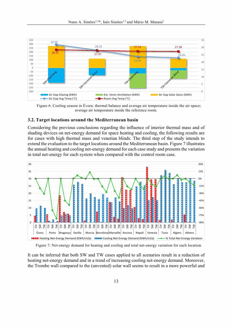
As mentioned before, although the Trombe wall system has been proven to provide notable heat loads and thus reduce significantly heating net-energy demand in buildings, overheating in the summer and mid-seasons is still a potential design issue to be considered in any passive solar building [11]. This concern is particularly highlighted by the results of experimental studies of Stazi and Mastrucci in Ancona, Italy ([10], [24]). Therefore, the second stage of the present study evaluates the influence of different shading devices – exterior overhang and venetian blinds, whose characteristics and operation schedules are specified in Table 6. Considering the conclusions on thermal mass influence, it was considered henceforth just the case studies with high thermal mass. Figure 6 illustrates the thermal balance for the air space and the average air temperatures during the entire cooling season (June-September), also in Évora. Simultaneously, it shows the influence of the passive systems on the temperature results. It can be noticed that overhang devices present much higher solar gains through the glazing than the venetian blind cases. When comparing both of the passive systems (SW and TW), it is visible that the continuous ventilation of the air space compartment promotes a substantial decrease in its average air temperature, e.g. from 32,05 ºC to 23,93 ºC in the case of the overhang protected systems and from 28,25 ºC to 23,05 ºC with the venetian blind, leading to a reduction of the air space average temperature of 25,3% and 18,5% respectively. These reductions led to a decrease of the average air temperature of the room ranging from 28,51 ºC (SW+Overhang) to 27,38 ºC (TW+Venetian blind).
‐1.0
‐0.5
0.0
0.5
1.0
1.5
2.0
2.5
3.0
19‐ago
07:00
13:00
19:00
20‐ago
7:00
13:00
19:00
21‐ago
7:00
13:00
19:00
22‐ago
7:00
13:00
19:00
23‐ago
7:00
13:00
19:00
24‐ago
7:00
13:00
19:00
25‐ago
7:00
13:00
19:00
26‐ago
High TM_SW Heat Gain (W/m2) High TM_TW Heat Gain (W/m2) Window Solar Gains (W/m2)
Low TM_SW Heat Gain (W/m2) Low TM_TW Heat Gain (W/m2)
Nuno A. Simões1,2*, Inês Simões1,2 and Mário M. Manaia2
13
Figure 6: Cooling season in Évora: thermal balance and average air temperature inside the air space;
average air temperature inside the reference room.
3.2. Target locations around the Mediterranean basin
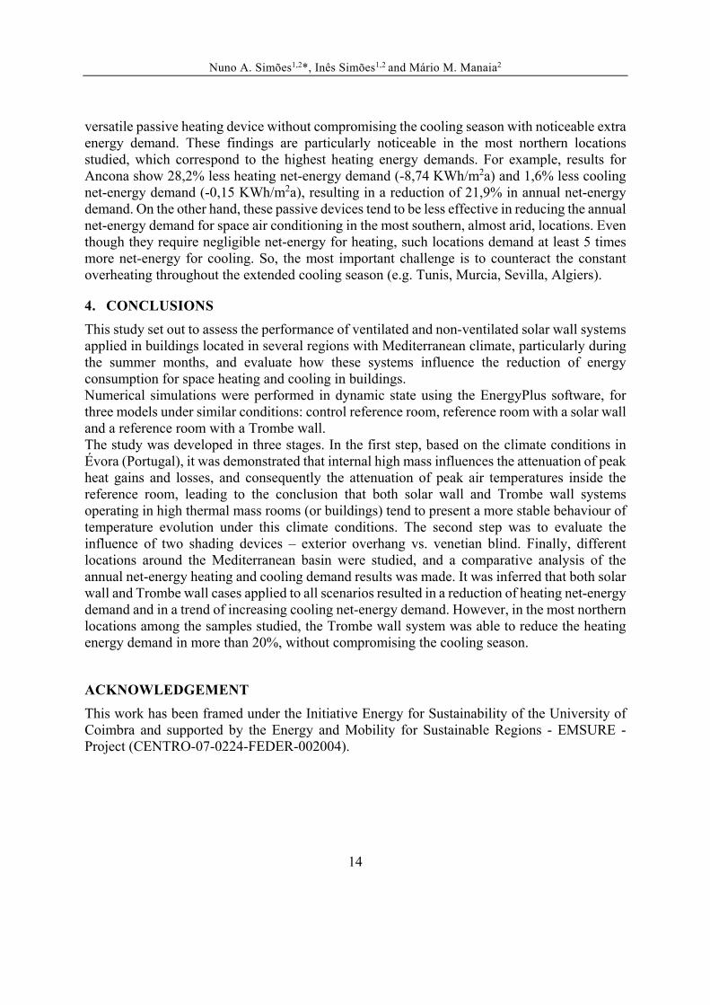
Considering the previous conclusions regarding the influence of interior thermal mass and of shading devices on net-energy demand for space heating and cooling, the following results are for cases with high thermal mass and venetian blinds. The third step of the study intends to extend the evaluation to the target locations around the Mediterranean basin. Figure 7 illustrates the annual heating and cooling net-energy demand for each case study and presents the variation in total net-energy for each system when compared with the control room case.
Figure 7: Net-energy demand for heating and cooling and total net-energy variation for each location.
It can be inferred that both SW and TW cases applied to all scenarios result in a reduction of heating net-energy demand and in a trend of increasing cooling net-energy demand. Moreover, the Trombe wall compared to the (unvented) solar wall seems to result in a more powerful and
32.05
28.25
23.93
23.0528.51 27.97
27.53 27.38
0
5
10
15
20
25
30
35
‐300
‐250
‐200
‐150
‐100
‐50
0
50
100
150
200
250
300
350
Air Gap Glazing (kWh) Ext. Vents Ventilation (kWh) Air Gap Solar Gains (kWh)Air Gap Avg Temp (°C) Room Avg Temp (°C)
‐90%
‐75%
‐60%
‐45%
‐30%
‐15%
0%
15%
30%
0
5
10
15
20
25
30
35
40
Ctr
SW TW Ctr
SW TW Ctr
SW TW Ctr
SW TW Ctr
SW TW Ctr
SW TW Ctr
SW TW Ctr
SW TW Ctr
SW TW Ctr
SW TW Ctr
SW TW Ctr
SW TW Ctr
SW TW
Évora Porto Bragança Sevilla Murcia Barcelona Marseille Ancona Napoli Venezia Tunis Algiers Athens
Heating Net‐Energy Demand (KWh/m2a) Cooling Net‐Energy Demand (KWh/m2a) % Total Net‐Energy Variation
Nuno A. Simões1,2*, Inês Simões1,2 and Mário M. Manaia2
14
versatile passive heating device without compromising the cooling season with noticeable extra energy demand. These findings are particularly noticeable in the most northern locations studied, which correspond to the highest heating energy demands. For example, results for Ancona show 28,2% less heating net-energy demand (-8,74 KWh/m2a) and 1,6% less cooling net-energy demand (-0,15 KWh/m2a), resulting in a reduction of 21,9% in annual net-energy demand. On the other hand, these passive devices tend to be less effective in reducing the annual net-energy demand for space air conditioning in the most southern, almost arid, locations. Even though they require negligible net-energy for heating, such locations demand at least 5 times more net-energy for cooling. So, the most important challenge is to counteract the constant overheating throughout the extended cooling season (e.g. Tunis, Murcia, Sevilla, Algiers).
4. CONCLUSIONS
This study set out to assess the performance of ventilated and non-ventilated solar wall systems applied in buildings located in several regions with Mediterranean climate, particularly during the summer months, and evaluate how these systems influence the reduction of energy consumption for space heating and cooling in buildings. Numerical simulations were performed in dynamic state using the EnergyPlus software, for three models under similar conditions: control reference room, reference room with a solar wall and a reference room with a Trombe wall. The study was developed in three stages. In the first step, based on the climate conditions in Évora (Portugal), it was demonstrated that internal high mass influences the attenuation of peak heat gains and losses, and consequently the attenuation of peak air temperatures inside the reference room, leading to the conclusion that both solar wall and Trombe wall systems operating in high thermal mass rooms (or buildings) tend to present a more stable behaviour of temperature evolution under this climate conditions. The second step was to evaluate the influence of two shading devices – exterior overhang vs. venetian blind. Finally, different locations around the Mediterranean basin were studied, and a comparative analysis of the annual net-energy heating and cooling demand results was made. It was inferred that both solar wall and Trombe wall cases applied to all scenarios resulted in a reduction of heating net-energy demand and in a trend of increasing cooling net-energy demand. However, in the most northern locations among the samples studied, the Trombe wall system was able to reduce the heating energy demand in more than 20%, without compromising the cooling season.
ACKNOWLEDGEMENT
This work has been framed under the Initiative Energy for Sustainability of the University of Coimbra and supported by the Energy and Mobility for Sustainable Regions - EMSURE - Project (CENTRO-07-0224-FEDER-002004).
Nuno A. Simões1,2*, Inês Simões1,2 and Mário M. Manaia2
15
REFERENCES
[1] P. Mendonça, “Habitar sob uma segunda pele : estratégias para a redução do impacto ambiental de construções solares passivas em climas temperados,” Universidade do Minho, 2005.
[2] G. Johnson, “Ligados ao Sol: Energia solar, prós e contras,” National Geographic Portugal, no 103, 2009.
[3] Eu and European Community, “Directive 2010/31/EU of the European Parliament and of the Council of 19 May 2010 on the energy performance of buildings,” Off. J. Eur. Union, pp. 13–35, 2010.
[4] O. Saadatian, K. Sopian, C. H. Lim, N. Asim, and M. Y. Sulaiman, “Trombe walls: A review of opportunities and challenges in research and development,” Renew. Sustain. Energy Rev., vol. 16, no. 8, pp. 6340–6351, 2012.
[5] J. Faludi and A. Menter, “Trombe Wall and Attached Sunspace,” Autodesk Design Academy, 2014. [Online]. Available: http://academy.autodesk.com/library/building-science/Trombe-wall-and-attached-sunspace. [Accessed: 05-Jan-2015].
[6] A. C. Martins, “Contribuição da Parede de Trombe na Redução do Consumo Energético dos Edifícios,” Dissertação de Mestrado em Engenharia Civil. Universidade de Trás-os-Montes e Alto Douro, 2010.
[7] A. Briga De Sá, “Parede de Trombe: Análise Experimental e Simulação de Desempenho Térmico.,” PhD Thesis in Civil Engineering. University of Beira Interior, 2011.
[8] A. Chel, J. K. Nayak, and G. Kaushik, “Energy conservation in honey storage building using Trombe wall,” Energy Build., vol. 40, pp. 1643–1650, 2008.
[9] S. Jaber and S. Ajib, “Optimum design of Trombe wall system in mediterranean region,” Sol. Energy, vol. 85, no. 9, pp. 1891–1898, 2011.
[10] F. Stazi, A. Mastrucci, and C. Di Perna, “Experimental and numerical study on the performance of solar walls in Mediterranean climates,” in World Renewable Energy Congress 2011 - Sweden, 2011, pp. 1938–1945.
[11] P. Torcellini and S. Pless, “Trombe walls in low-energy buildings: Practical experiences,” Prepr. www. nrel. gov/docs/fy04osti/ …, no. July, 2004.
[12] A. Mastrucci, “Experimental and numerical study on solar walls for energy saving, thermal comfort and sustainability of residential buildings,” Università Politecnica delle Marche, 2013.
[13] E. Iso, “EN ISO 13790: 2008 Energy performance of buildings-Calculation of energy use for space heating and cooling,” Order A J. Theory Ordered Sets Its Appl., vol. 2008, no. 8, pp. 3190–200, 2008.
[14] E. Iso, “EN 15265:2007 - Energy performance of buildings — Calculation of energy needs for space heating and cooling using dynamic methods — General criteria and validation procedures,” Eur. Comm. Stand., 2007.
[15] M. Veríssimo, M. Almeida, and L. Bragança, “Jee - Janela Eco-Eficiente ( Eco Efficient Window ); Development of a high performance standard window.,” Portugal
Nuno A. Simões1,2*, Inês Simões1,2 and Mário M. Manaia2
16
SB07: Sustainable Construction, Materials and Practices - Challenge of the Industry for the New Millennium, no. L. Bragança et al. (Eds.). IOS Press, 2007.
[16] M. Kottek, J. Grieser, C. Beck, B. Rudolf, and F. Rubel, “World map of the Köppen-Geiger climate classification updated,” Meteorol. Zeitschrift, vol. 15, no. 3, pp. 259–263, 2006.
[17] K. Tsikaloudaki, K. Laskos, and D. Bikas, “On the establishment of climatic zones in Europe with regard to the energy performance of buildings,” Energies, vol. 5, no. 1, pp. 32–44, 2012.
[18] C. Bin, C. Cuiying, and Y. Wenxiu, “A Calculation Model of Passive Solar House with Trombe Wall,” in Renewable Energy Proceedings, 2006.
[19] G. Gan, “A parametric study of Trombe walls for passive cooling of buildings,” Energy Build., vol. 27, no. 1, pp. 37–43, Feb. 1998.
[20] L. Zalewski, S. Lassue, B. Duthoit, and M. Butez, “Study of solar walls - Validating a simulation model,” Build. Environ., vol. 37, pp. 109–121, 2002.
[21] T. G. Özbalta and S. Kartal, “Heat gain through Trombe wall using solar energy in a cold region of Turkey,” vol. 5, no. 18, pp. 2768–2778, 2010.
[22] N. P. Nwachukwu and W. I. Okonkwo, “Effect of an Absorptive Coating on Solar Energy Storage in a Thrombe wall system,” Energy Build., vol. 40, no. 3, pp. 371–374, 2008.
[23] W. Liping and L. Angui, “A numerical study of Trombe wall for enhancing stack ventilation in buildings,” Proc. 23rd Conf. Passiv. Low Energy Archit., no. September, pp. II671–II677, 2006.
[24] F. Stazi, C. Di Perna, C. Filiaci, and a Stazi, “The Solar Wall in the Italian Climates,” vol. 2, no. 1, pp. 31–39, 2008.
[25] P. G. Ellis, “Development and Validation of the Unvented Trombe Wall Model in Energyplus,” Exch. Organ. Behav. Teach. J., 2003.
[26] Designbuilder Software Ltd, “Designbuilder help - Trombe Walls.” [Online]. Available: http://www.designbuilder.co.uk/helpv3/Content/Trombe_Walls.htm.