SystemC-Unit: a unit testing framework for SystemC
50
UNIVERSIDADE FEDERAL DO RIO GRANDE DO SUL INSTITUTO DE INFORMÁTICA BACHARELADO EM ENGENHARIA DE COMPUTAÇÃO FELIPE DIENSTMANN MUSSE SystemC-Unit: a unit testing framework for SystemC Trabalho de graduação. Trabalho realizado no Grenoble INP dentro do acordo de dupla diplomação UFRGS - Grenoble INP. Orientadora brasileira: Prof. Dra. Érika Cota Orientador francês: Prof. Dr. Matthieu Moy Porto Alegre 2016
Transcript of SystemC-Unit: a unit testing framework for SystemC
UNIVERSIDADE FEDERAL DO RIO GRANDE DO SUL INSTITUTO DE INFORMÁTICA
BACHARELADO EM ENGENHARIA DE COMPUTAÇÃO
FELIPE DIENSTMANN MUSSE
SystemC-Unit: a unit testing framework for SystemC
Trabalho de graduação.
Trabalho realizado no Grenoble INP dentro do acordo de dupla diplomação UFRGS - Grenoble INP.
Orientadora brasileira:Prof. Dra. Érika Cota
Orientador francês:Prof. Dr. Matthieu Moy
Porto Alegre2016
CIP – CATALOGAÇÃO NA PUBLICAÇÃO
Musse, Felipe Dienstman
SystemC-Unit: a unit testing framework for SystemC / Felipe Dienstmann Musse. – Porto Alegre: Engenharia de Computação da UFRGS, 2016.
50 f.: il.
Trabalho de conclusão (Bacharelado) – Universidade Federal do Rio Grande do Sul. Bacharelado em Engenharia de Computação, Porto Alegre, BR–RS, 2016. Orientadora brasileira: Érika Cota; Orientador francês: Matthieu Moy.
1. SystemC. 2. Teste unitário. 3. Modelização a nível transa-cional. 4. Teste de software. 5. Qualidade de software. I. Co- ta, Érika. II. Título.
UNIVERSIDADE FEDERAL DO RIO GRANDE DO SULReitor: Prof. Carlos Alexandre NettoVice-Reitor: Prof. Rui Vicente OppermannPró-Reitora de Graduação: Prof. Sérgio Roberto Kieling FrancoDiretor do Instituto de Informática: Prof. Luís da Cunha LambCoordenador da ECP: Prof. Raul Fernando WeberBibliotecária-Chefe do Instituto de Informática: Beatriz Regina Bastos Haro
RESUMO
A biblioteca de modelização SystemC é utilizada para construir modelos em software de sistemas de hardware complexos (tais como Systems on Chip), os quais são chamados protótipos virtuais. Na empresa STMicrolectronics, tais modelos são desenvolvidos com o auxílio de elementos reutilizáveis, os quais facilitam a representação de componentescomumente encontrado em diferentes sistemas de hardware. Garantir o bom funciona-mento destes elementos é fundamental, uma vez que os modelos aos quais eles são integrados são utilizados em atividades importantes, tais como desenvolvimento de software embarcado e verificação funcional.
Este trabalho consiste no desenvolvimento de um framework de teste unitário para SystemC, o qual permite o teste destes elementos reutilizáveis. O contexto de desen-volvimento em que eles são utilizados é inicialmente analisado, assim como os problemas dos testes existentes. Em seguida, alguns frameworks de teste unitário de código livre são estudados para considerar sua aplicabilidade à solução destes problemas. Com base nos resultados destas análises, as características da solução proposta são definidas. Finalmente, o framework, o qual é denominado SystemC-Unit, é implemen-tado, testado e validado.
Palavras-chave: SystemC, teste unitário, modelização a nível transacional, teste de software, qualidade de software.
Resumo estendido
Este é um resumo estendido em português para a Universidade Federal do Rio Grande do Sul do trabalho original que segue. O trabalho de conclusão original, em inglês, foi apresentado no Grenoble INP - Ensimag através do programa de dupla diplomação entre as duas universidades.
1 Introducao
1.1 ContextoUm System on Chip (SoC) e um circuito integrado que contem, em um unicochip, todos os componentes necessarios a operacao de um computador, tais comounidades centrais de processamento (CPUs), memorias, perifericos e interfaces.O desenvolvimento de um SoC envolve uma quantidade significativa de softwareembarcado, tais como firmware e drivers. No fluxo de projeto tradicional, estesoftware apenas e desenvolvido apos o design e fabricacao do circuito. No en-tanto, a fim de manter competitividade e reduzir o time-to-market do chip, estesoftware deve ser desenvolvido em paralelo com o hardware.
Uma solucao para este problema e construir um modelo simples do SoC emsoftware, o qual modeliza apenas o suficiente para desenvolver o software ne-cessario. A tecnica de modelizacao a nıvel transacional pode ser utilizada paraobter tais modelos, os quais sao chamados de prototipos virtuais. Por poderemser escritos e simulados rapidamente, tais modelos sao apropriados para desenvol-ver o software necessario antes da fabricacao do circuito.
1.2 Exemplo de prototipagem virtual na industriaNa STMicroelectronics (comumente chamada ST), uma multinacional franco-italiana fabricante de eletronicos e semicondutores, prototipos virtuais sao uti-lizados para antecipar o desenvolvimento do software embarcado para produtoscomo Systems on Chip. A equipe de Modelizacao a Nıvel de Sistema (SLM, deSystem Level Modeling) e a referencia da empresa para as atividades relacionadasaos prototipos virtuais, os quais sao construıdos com SystemC, uma biblioteca demodelizacao para C++.
A fim de facilitar o desenvolvimento destes modelos, esta equipe desenvolve emantem um conjunto de elementos reutilizaveis para SystemC (tambem chama-dos de briques). Estes elementos representam entidades comumente encontradasem sistemas de hardware, tais como bancos de registradores e controladores deinterrupcoes. Gracas ao uso destes briques, o processo de escrever prototipos vir-tuais e acelerado de forma significativa; alem disso, os modelos resultantes saomais homogeneos do que se cada equipe os tivesse desenvolvido do zero.
Garantir o funcionamento correto destes briques reutilizaveis e fundamental,uam vez que eles sao integrados a modelos que sao utilizados em atividades im-portantes, tal como o desenvolvimento de software embarcado. Um brique nao-operacional pode causar atrasos na entrega de um produto ao mercado. Alemdisso, eles nao sao apenas utilizados pela equipe SLM, mas tambem por equi-pes de desenvolvimento de produtos da ST que desejam fazer uso de prototipos
I
virtuais em seus projetos.
1.3 ProblemaDevido aos riscos de falha, uma certa quantidade de testes foi desenvolvida pracada brique reutilizavel. Geralmente, os testes relativos a uma funcionalidadede um brique sao escritos por quem a implementou. Os testes existentes foramportanto desenvolvidos e modificados por diferentes pessoas, e isto foi feito demaneira ad-hoc. Como resultado, eles apresentam alguns problemas:
• Ha muita repeticao de codigo (tanto entre os testes de um unico brique comoentre os testes de diferentes briques), o que os faz desnecessariamente ex-tensos e difıceis de entender, manter e modificar;
• Os testes nao descrevem claramente quais aspectos de uma funcionalidadeestao sendo verificados; como resultado, os testes recorrentemente se so-brepoem, enquanto outros aspectos nao sao testados;
• Testes similares sao estruturados diferentemente, o que complica tanto o seuentendimento como a sua manutencao:
– Operacoes comuns, tal como a comparacao entre valores esperados eefetivos, sao efetuadas assistematicamente;
– Os resultados dos testes sao heterogeneos e desorganizados; isto tornadifıcil a sua analise tanto em caso de regressao como de nao-regressao.
1.4 ObjetivosA importancia de testar os briques reutilizaveis em SystemC desenvolvidos pelaequipe SLM foi estabelecida. Alem disso, como mostrado acima, os testes exis-tentes apresentam problemas significativos que dificultam sua compreensao, ma-nutencao e escrita. O objetivo principal deste projeto e portanto resolver estasquestoes a fim de garantir a verificacao correta do funcionamento destes briques,aumentando assim a produtividade em atividades de teste.
A solucao proposta e desenvolver um framework de teste que:
• Proponha servicos simples que facilitem o trabalho dos desenvolvedores eos guie em direcao a testes homogeneos e de qualidade: comparacao devalores esperados, relatorios de erros, estrutura padrao de testes, e assimpor diante;
• Forneca resultados de testes homogeneos e relevantes de forma a facilitar asua analise para fins de regressao e nao-regressao;
II
• Integre-se facilmente ao ambiente de desenvolvimento de prototipos virtuaisem SystemC.
2 Visao geral do trabalhoInicialmente, identificam-se requisitos que devem ser respeitados para o desen-volvimento da solucao. Alguns deles sao inerentes a utilizacao da biblioteca Sys-temC, enquanto outros sao devidos ao ambiente de desenvolvimento da equipeSLM. Requisitos adicionais sao extraıdos atraves da analise dos problemas nostestes existentes de um exemplo de brique reutilizavel.
Em seguida, alguns frameworks de teste de codigo aberto sao estudados afim de verificar sua aplicabilidade ao problema considerado e de extrair novosrequisitos. Frameworks correspondendo a duas tecnicas de testes sao conside-rados: desenvolvimento guiado por compartamento (BDD, de behavior drivendevelopment), uma tecnica relativamente moderna na qual os testes sao baseadosna descricao textual das funcionalidades do software, e teste unitario, uma abor-dagem classica para o teste de software. Baseado nestas analises, estabelece-seuma lista definitiva de requisistos a serem considerados para o desenvolvimentodo framework de teste. Alem disso, conclui-se que os frameworks estudados naosao adaptados para o teste de briques SystemC. Decide-se por desenvolver umframework do zero.
Por fim, propoe-se uma solucao para os problemas apresentados, a qual e cha-mada SystemC-Unit. Primeiramente, estabelece-se uma lista de funcionalidadesa serem fornecidas de forma a satisfazer os requisitos estabelecidos. Em seguida, oframework e implementado de forma incremental. Sua implementacao tambem etestada a fim de verificar sua corretude. Por fim, exercıcios de validacao sao efetu-ados, os quais permitem a identificacao de funcionalidades ausentes e a verificacaode que a solucao atende as necessidades de seus usuarios.
3 ResultadosAs funcionalidades consideradas necessarias para a resolucao do problema emquestao foram integralmente implementadas e testadas. A implementacao dasolucao proposta tem cerca de 4 mil linhas de codigo, bem menos do que os fra-meworks de codigo livre estudados. Atividades de validacao permitiram constataruma reducao media de 21% no tamanho (em linhas de codigo) dos testes escritoscom SystemC-Unit em comparacao aos testes previos. Uma primeira versao ofi-cial do framework foi entregue a equipe SLM e esta sendo atualmente utilizadapara o teste de briques reutilizaveis.
III
Grenoble INP – ENSIMAGÉcole Nationale Supérieure d’Informatique et de Mathématiques Appliquées
End-of-Studies Project – Final Report
Undertaken at STMicroelectronics
SystemC-Unit: a unit testingframework for SystemC
Felipe DIENSTMANN MUSSE3rd Year – Embedded Systems and Software Option
February 15th 2016 – July 15th 2016
STMicroelectronics Internship supervisor12 rue Jules Horowitz Jérôme CORNETBP 217 School mentor38019 Grenoble Cedex Matthieu MOY
AbstractThe SystemC modelization library is used to build software models of complex hardware
systems (such as Systems on Chip), which are called virtual prototypes. At STMicroelectronics,these models are developed with the aid of reusable elements which facilitate the representationof components commonly found in different hardware systems. Assuring the correct behaviorof these elements is paramount, as models to which they are integrated are used in importantactivities, such as embedded software development and functional verification.
This work consists in the development of a unit testing framework for SystemC which allowsthe testing of these reusable elements. The developmment context in which they are used isinitially analyzed, as well as the problems in existing tests. Next, some unit testing open-sourceframeworks are studied to consider their applicability to the solution of these problems. Basedon the results of these analyses, the features of the proposed solution are defined. Finally, theframework, which is called SystemC-Unit, is implemented, tested and validated.
Keywords: SystemC, unit testing, transaction-level modeling, software testing, softwarequality.
Acknowledgments
First of all, I would like to thank STMicroelectronics for the opportunity to undertake thisinternship. My sincere thanks towards everybody with whom I worked during these five monthsfor receiving me so well. I am very grateful to my team manager Laurent Maillet-Contoz, whoseadvice greatly helped me during this internship. I would also like to thank my school mentorMatthieu Moy for promptly answering my questions and for having prepared me so well forthis project with his Transaction-Level Modeling courses. I am also very thankful to my secondsupervisor, Érika Cota, who helped to greatly improve this text with her many remarks andsuggestions.
I am especially thankful to my internship supervisor Jérôme Cornet. His guidance was themain reason for the success of this project. Were it not him for, this internship would not havebeen half as interesting and challenging as it was. I deeply thank him for his patient explanationswhen I did not easily accept his instructions and for sharing all his knowledge with me.
My sincere thanks towards both my universities, ENSIMAG (École nationale supérieured’informatique et de mathématiques appliquées) and UFRGS (Universidade Federal do RioGrande do Sul). I am very thankful to CAPES (Coordenação de Aperfeiçoamento de Pessoalde Nível Superior) and to my exchange coordinator Claudio Geyer for providing me the oppor-tunity to study in France and to undertake this internship.
Finally, I would like to fondly thank my parents – the older I get, the more I realize thateverything I ever achieve will be thanks to them.
3
Contents
1 Introduction 61.1 Context . . . . . . . . . . . . . . . . . . . . . . . . . . . . . . . . . . . . . . . 6
1.1.1 SoC and software development . . . . . . . . . . . . . . . . . . . . . . . 61.1.2 Model terminology . . . . . . . . . . . . . . . . . . . . . . . . . . . . . 71.1.3 Example of virtual prototyping in the industry . . . . . . . . . . . . . . . 8
1.2 Problem to solve . . . . . . . . . . . . . . . . . . . . . . . . . . . . . . . . . . . 91.3 Objectives . . . . . . . . . . . . . . . . . . . . . . . . . . . . . . . . . . . . . . 101.4 Manuscript Organization . . . . . . . . . . . . . . . . . . . . . . . . . . . . . . 10
2 Background 112.1 SystemC . . . . . . . . . . . . . . . . . . . . . . . . . . . . . . . . . . . . . . . 112.2 Software testing concepts . . . . . . . . . . . . . . . . . . . . . . . . . . . . . . 12
3 Requirements 153.1 Initial constraints . . . . . . . . . . . . . . . . . . . . . . . . . . . . . . . . . . 153.2 Additional Constraints . . . . . . . . . . . . . . . . . . . . . . . . . . . . . . . 16
4 Analysis of existing test frameworks 224.1 Behavior Driven Development framework . . . . . . . . . . . . . . . . . . . . . 22
4.1.1 The BDD methodology . . . . . . . . . . . . . . . . . . . . . . . . . . . 224.1.2 The Cucumber framework . . . . . . . . . . . . . . . . . . . . . . . . . 234.1.3 Adapting Cucumber to SystemC . . . . . . . . . . . . . . . . . . . . . . 264.1.4 Conclusions about BDD approach . . . . . . . . . . . . . . . . . . . . . 27
4.2 C++ unit testing solutions . . . . . . . . . . . . . . . . . . . . . . . . . . . . . . 274.2.1 Studied frameworks . . . . . . . . . . . . . . . . . . . . . . . . . . . . . 284.2.2 Tests reimplementation . . . . . . . . . . . . . . . . . . . . . . . . . . . 294.2.3 Conclusion . . . . . . . . . . . . . . . . . . . . . . . . . . . . . . . . . 29
4.3 Results . . . . . . . . . . . . . . . . . . . . . . . . . . . . . . . . . . . . . . . . 29
5 Proposed unit testing framework for SystemC 315.1 Features . . . . . . . . . . . . . . . . . . . . . . . . . . . . . . . . . . . . . . . 315.2 Implementation overview . . . . . . . . . . . . . . . . . . . . . . . . . . . . . . 335.3 Example Test . . . . . . . . . . . . . . . . . . . . . . . . . . . . . . . . . . . . 345.4 Implementation details . . . . . . . . . . . . . . . . . . . . . . . . . . . . . . . 365.5 Testing . . . . . . . . . . . . . . . . . . . . . . . . . . . . . . . . . . . . . . . . 395.6 Documentation . . . . . . . . . . . . . . . . . . . . . . . . . . . . . . . . . . . 395.7 Validation . . . . . . . . . . . . . . . . . . . . . . . . . . . . . . . . . . . . . . 40
4
6 Concluding Remarks 41
Bibliography 43
List of Figures
1.1 Terminology for different entities of a virtual prototype . . . . . . . . . . . . . . 71.2 System Level Modeling team activities . . . . . . . . . . . . . . . . . . . . . . . 8
2.1 Overview of the execution of a SystemC model . . . . . . . . . . . . . . . . . . 12
3.1 Simplified structure of current tests . . . . . . . . . . . . . . . . . . . . . . . . . 183.2 Construction and destruction of test modules . . . . . . . . . . . . . . . . . . . . 19
4.1 Cucumber C++ inner workings . . . . . . . . . . . . . . . . . . . . . . . . . . . 24
5.1 Diagram exemplifying structure of tests developed with the framework . . . . . . 325.2 Interactions between the framework’s packages and the user-defined tests . . . . 34
5
1. Introduction
1.1 Context
1.1.1 SoC and software developmentA System on Chip (SoC) is an integrated circuit which contains, in a single chip, all the com-ponents required for the operation of a computer, such as central processing units (CPUs), mem-ories, peripherals and interfaces. These elements commonly take the form of IP (intellectualproperty) cores, which are blocks of logic or data whose objective is to be reused for the devel-opment of different chips.
SoCs (and other electronic circuits) are commonly designed with hardware description lan-guages (HDL). They allow to describe the structure and behavior of a circuit with different levelsof abstraction and the resulting models may be analysed and simulated. The two major hardwaredescription languages are VHDL and Verilog. The most common way to represent a digital cir-cuit with an HDL is with a register-transfer level (RTL) of abstraction, that is, in terms of theflow of data between registers and the operations performed on this data. After a RTL modelhas been developed, lower level descriptions may be derived from it, which are then used tomanufacture the circuit.
SoCs involve a significant amount of software development, such as firmware and drivers.In the regular SoC design flow, this software is only developed after the circuit has been fullydesigned and manufactured. However, in order to maintain competitivity by reducing the cir-cuit’s time-to-market, the software should be developed in parallel with the hardware. This iscomplicated to achieve using the circuit’s RTL representation: since the level of abstraction israther low, simulating the hardware’s operation with the software takes too much time. More-over, ideally it should not be necessary to wait for the RTL description to be finished to start thesoftware development.
A solution is to build a simpler model of the circuit with a higher level of abstraction, onlymodeling what is necessary to develop the required software. This is exactly the objective of thetransaction-level modeling (TLM) approach. With this technique, models are commonly builtusing a general-purpose programming language. The idea is to separate the details of commu-nication among the circuit’s modules from the actual information exchange (transactions). Eachof the hardware’s subcomponents may hence be freely developed with the considered program-ming language without considering the circuit’s clock (cycle-less model) as long as it respectsthe defined interface. As a result, when compared to RTL models, TLM ones are simpler to writeand simulate faster, and therefore are suitable to develop the required software before the circuitis fabricated. For the same reasons, they are also useful for other activities, such as functionalverification, architectural exploration and performance modeling.
In order to model hardware systems with a TLM level of abstraction, one may use a special-
6
ized software library. An example is SystemC [1], a standardized C++ library which is presentedin Section 2.1 in more details.
1.1.2 Model terminologyTLM models which mainly aim to anticipate the embedded software development are generallycalled virtual prototypes (prototype, as it is an early model of a product that has not been fullydesigned; virtual, as it is a software model, not a physical one). A complete model of a circuitis composed of blocks1 which are differently named according to their level in the system’shierarchy. Making the distinction between them is paramount to understand this document.
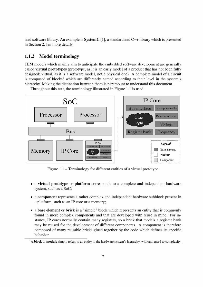
Throughout this text, the terminology illustrated in Figure 1.1 is used:
Figure 1.1 – Terminology for different entities of a virtual prototype
• a virtual prototype or platform corresponds to a complete and independent hardwaresystem, such as a SoC;
• a component represents a rather complex and independent hardware subblock present ina platform, such as an IP core or a memory;
• a base element or brick is a "simple" block which represents an entity that is commonlyfound in more complex components and that are developed with reuse in mind. For in-stance, IP cores normally contain many registers, so a brick that models a register bankmay be reused for the development of different components. A component is thereforecomposed of many reusable bricks glued together by the code which defines its specificbehavior.
1A block or module simply refers to an entity in the hardware system’s hierarchy, without regard to complexity.
7
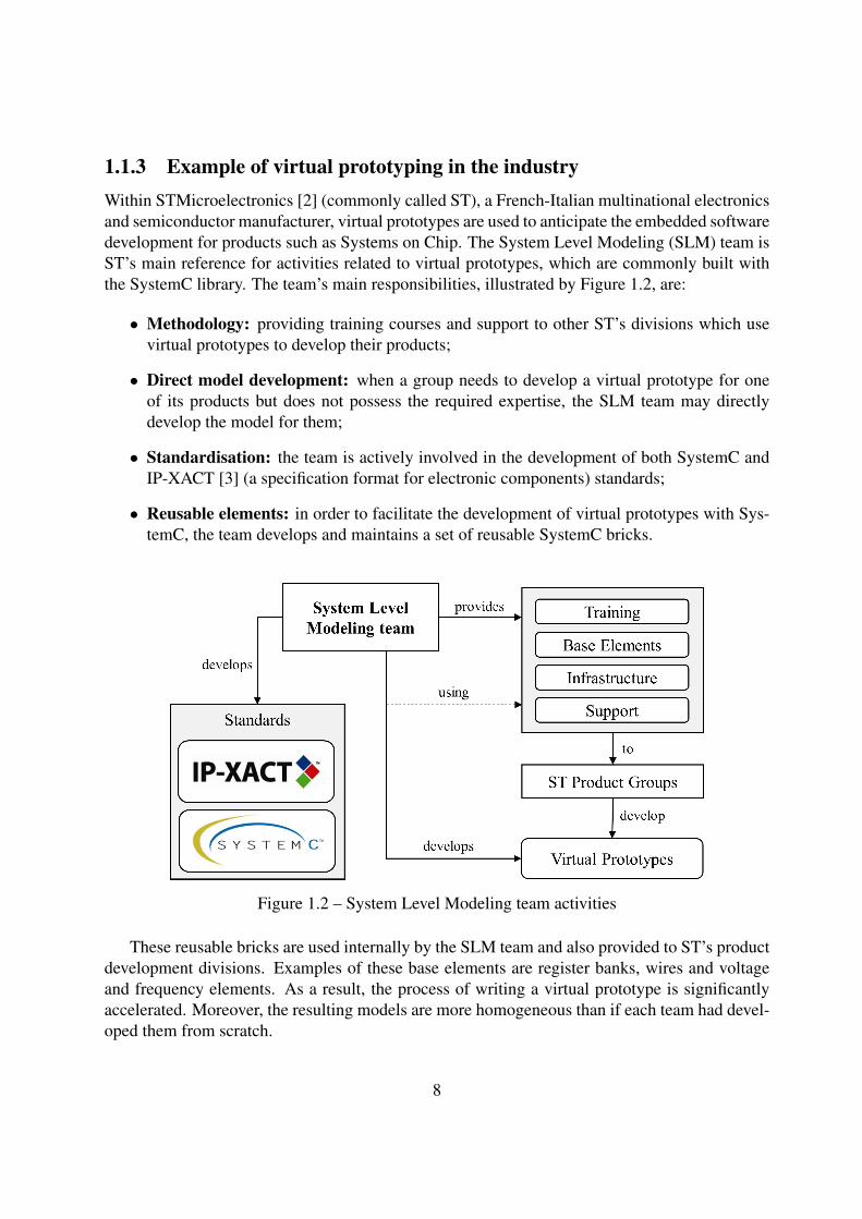
1.1.3 Example of virtual prototyping in the industryWithin STMicroelectronics [2] (commonly called ST), a French-Italian multinational electronicsand semiconductor manufacturer, virtual prototypes are used to anticipate the embedded softwaredevelopment for products such as Systems on Chip. The System Level Modeling (SLM) team isST’s main reference for activities related to virtual prototypes, which are commonly built withthe SystemC library. The team’s main responsibilities, illustrated by Figure 1.2, are:
• Methodology: providing training courses and support to other ST’s divisions which usevirtual prototypes to develop their products;
• Direct model development: when a group needs to develop a virtual prototype for oneof its products but does not possess the required expertise, the SLM team may directlydevelop the model for them;
• Standardisation: the team is actively involved in the development of both SystemC andIP-XACT [3] (a specification format for electronic components) standards;
• Reusable elements: in order to facilitate the development of virtual prototypes with Sys-temC, the team develops and maintains a set of reusable SystemC bricks.
Figure 1.2 – System Level Modeling team activities
These reusable bricks are used internally by the SLM team and also provided to ST’s productdevelopment divisions. Examples of these base elements are register banks, wires and voltageand frequency elements. As a result, the process of writing a virtual prototype is significantlyaccelerated. Moreover, the resulting models are more homogeneous than if each team had devel-oped them from scratch.
8
Even though these base elements may seem simple at first glance, the fact that platforms willinteract with them differently generates a need for them to be highly configurable. Moreover,when a product team requires a feature that is not present in a base element, it is requested to theSLM team, which subsequently implements it and releases the updated brick to all of ST. As aconsequence, these elements are relatively complex.
Since these base elements are integrated into many components and platforms which areused in important activities such as embedded software development and functional verification,assuring their correct behavior is paramount. For instance, a platform which contains a buggedbrick may not properly model the actual circuit; the software that has been developed with itmay work with the virtual prototype, but not with the real system. It would be very hard to findthe problem since, in the platform’s developers vision, the circuit’s specification was correctlytranslated into a virtual prototype – the problem is not in their model, but rather in the baseelements of which they made use.
A non-operational brick may hence lead to very time-consuming and expensive troubleshoot-ing. Moreover, frequent bugs would have an impact on the team’s reputation, as these elementsare provided to other divisions. Testing is therefore an essential activity within the SLM team –and not a trivial one, since the implementations of these bricks are certainly substantial.
1.2 Problem to solveDue to the involved risks of failure, a number of tests is designed for each reusable bricks.Generally, the tests concerning a feature are written by whom implemented it. The existing testshave therefore been developed and modified by different people and this has been done in an adhoc fashion. As a result, they are rather problematic:
• There is a lot of code repetition (between both tests for a single brick and tests for differentbricks), which makes them unnecessarily large and difficult to understand, maintain andmodify;
• The tests do not clearly describe which feature’s aspects are being verified; as a result, theyrecurrently superpose themselves, whereas other functionalities are left untested;
• Similar tests are rather differently structured, and this complicates both their understandingand maintenance:
– Common operations, such as comparisons between expected and actual values, areunsystematically performed;
– The reporting of tests results is heterogeneous and disorganized: this makes it hardto analyze the tests results for both regression and non-regression purposes.
9
1.3 ObjectivesThe importance of testing the SystemC reusable bricks developed by the System Level Modelingteam has been established. Moreover, as shown above, the existing tests present some significantproblems which encumber their comprehension, maintenance and writing. The main objectiveof this project is hence to solve these issues in order to assure the proper verification of thesebrick’s behavior and to increase productivity in testing related activities.
The proposed solution is to develop a test framework which:
• Proposes simple services to facilitate the developers’ work and steer them towards qual-ity and homogeneous tests: expected value comparison, error reporting, standardized teststructure, and so on;
• Provides homogeneous and relevant reporting of tests results in order to facilitate bothregression and non-regression analysis;
• Easily integrates itself to the development environment of SystemC virtual prototypes.
Since the System Level Modeling team does not suffer from Not-Invented-Here syndrome2,an auxiliary objective is to analyze the state of art of testing practices outside of ST. The suitabil-ity of a rather new methodology called Behavior Driven Development (BDD) for the testing ofthe SystemC bricks is evaluated. Moreover, the idea is not to blindly implement the frameworkfrom scratch, but rather to first analyze existing open-source testing libraries which may provideelements or ideas to facilitate its development. Both these analyses are carried out considering apossible extension of the framework in order to allow the testing of SystemC components (morecomplex blocks which are built upon reusable bricks).
1.4 Manuscript OrganizationThe text is organized as follows:
• Chapter 2 presents the technical background and concepts which are required for the un-derstanding of this text.
• Next, Chapter 3 details the problems in existing tests and identifies the requirements to berespected by the proposed solution.
• Chapter 4 then analyses existing open-source test frameworks in order to verify their ap-plicability to the presented problem.
• Afterwards, Chapter 5 presents the proposed solution and gives an overview of its devel-opment, validation and testing.
• Finally, Chapter 6 concludes with the results and perspectives of this work.
2Not invented here syndrome [4] is the tendency of both individual developers and entire organizations to rejectsuitable external solutions to software development problems in favor of internally developed solutions.
10
2. Background
This chapter reviews the main concepts required for the development of this work. First, somedetails of the SystemC virtual prototyping library are presented. Afterwards, the needed softwaretesting concepts are shown and explained.
2.1 SystemCSystemC [1] is a standardized C++ library which allows the modeling of both hardware andsoftware of electronic systems at multiple levels of abstraction. It provides classes to represent,among others, the decomposition of a system into modules, the connectivity and communicationbetween those modules, the passing of simulated time, the synchronization of concurrent mod-ules and the data types commonly found in digital hardware. The library also includes a simula-tion kernel and offers TLM capabilities to abstract communication between modules. SystemCis defined and promoted by the Accellera Systems Initiative (ASI) [5], an organization of whichmost major EDA (electronic design automation) software vendors and users are participants (in-cluding ST). The library is defined by the IEEE (Institute of Electrical and Electronics Engineers)standard 1666-2011 and an open-source reference implementation is maintained by ASI.
A SystemC model is composed of different modules, which are instances of the sc_moduleclass. These modules may contain processes, which are actually member functions that run con-currently and represent the circuit’s parallel behavior. The model’s execution occurs within thesc_main() function, which is defined by the user and called by SystemC’s simulation kernel.A minimalistic example of such a function is shown in Listing 2.1. This execution consists oftwo phases:
Listing 2.1 – Minimalistic example of sc_main() function1 int sc_main(int argc, char ** argv)2 {3 Cpu cpu("CPU");4 Peripheral periph("Peripheral");5
6 sc_signal<bool> irq;7 periph.irq_out(irq);8 cpu.irq_in(irq);9
10 sc_start();11 return 0;12 }
• The construction is the definition of the model’s architecture. Within the sc_main()function, the model’s modules are instantiated (lines 3 and 4) and connected together (lines
11
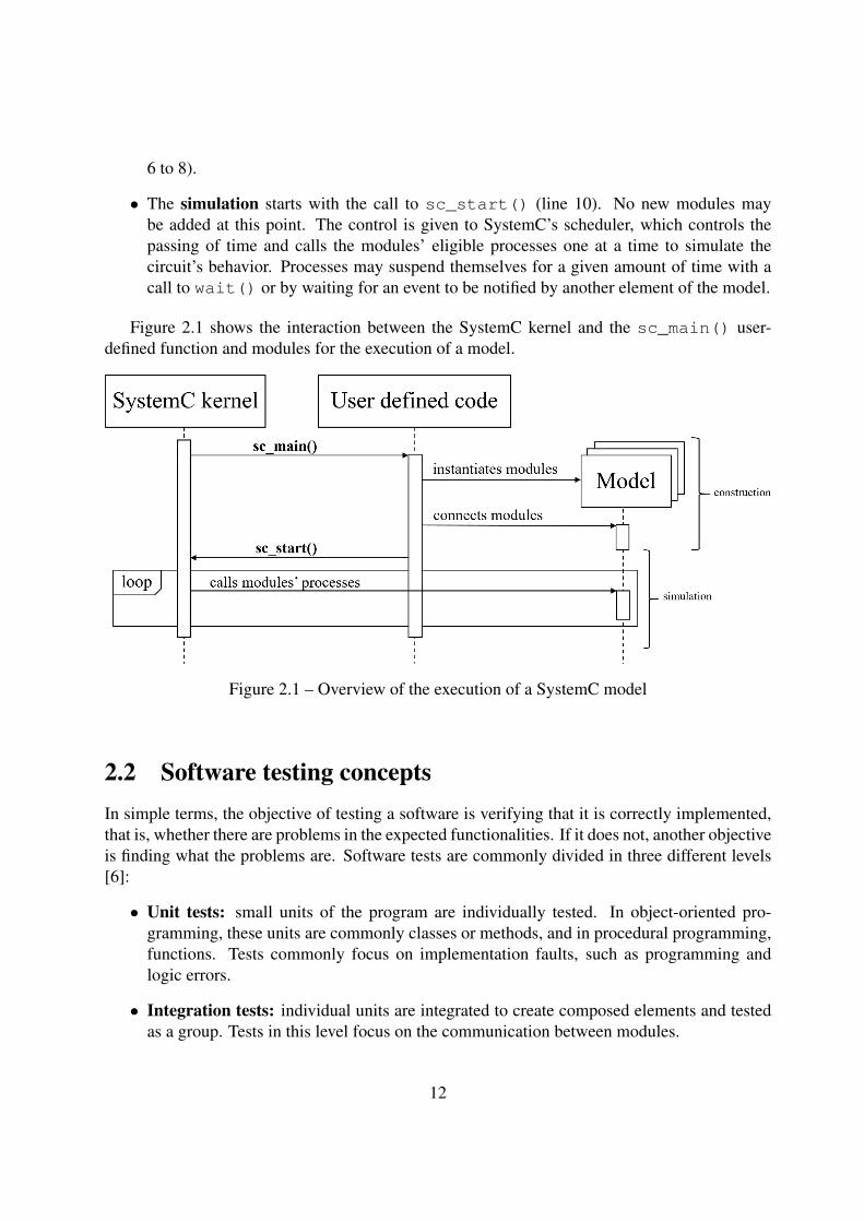
6 to 8).
• The simulation starts with the call to sc_start() (line 10). No new modules maybe added at this point. The control is given to SystemC’s scheduler, which controls thepassing of time and calls the modules’ eligible processes one at a time to simulate thecircuit’s behavior. Processes may suspend themselves for a given amount of time with acall to wait() or by waiting for an event to be notified by another element of the model.
Figure 2.1 shows the interaction between the SystemC kernel and the sc_main() user-defined function and modules for the execution of a model.
Figure 2.1 – Overview of the execution of a SystemC model
2.2 Software testing conceptsIn simple terms, the objective of testing a software is verifying that it is correctly implemented,that is, whether there are problems in the expected functionalities. If it does not, another objectiveis finding what the problems are. Software tests are commonly divided in three different levels[6]:
• Unit tests: small units of the program are individually tested. In object-oriented pro-gramming, these units are commonly classes or methods, and in procedural programming,functions. Tests commonly focus on implementation faults, such as programming andlogic errors.
• Integration tests: individual units are integrated to create composed elements and testedas a group. Tests in this level focus on the communication between modules.
12
• System tests: all the elements of the complete system are integrated and the software istested as a whole. Tests in this level commonly focus on the overall functionality providedby the modules altogether.
Unit tests are automated through the use of unit testing frameworks, which provide supportfor developing and executing them. An example is the xUnit [7] family, a collection of unittesting frameworks that support different programming languages and share a similar test archi-tecture. These frameworks provide generic test classes which are extended by the user in orderto write tests. The tool may then execute all tests and indicate what the results were.
When using unit testing frameworks, tests take the form of what is called a test case in thexUnit architecture. A test case is a sequence of code which exercises a certain behavior of theelement under test with a given stimuli and verifies its correct operation. A test case is composedof three parts:
1. Setup: the element under test is initialized to a known state, i.e., the preconditions of thetest case. The setup code may also be called test fixture [8]. This setup code may be putdirectly in the test method (in-line setup) or separately so that it may be used by differenttest cases to avoid code repetition (delegated setup if invoked explicitly by the test code orimplicitly by the framework);
2. Exercise: the test code interacts with the element under test, that is, the object or methodto be tested is called (possibly with specific test data or inputs);
3. Verification: the results of the calls are compared to the expected ones. This is usuallydone through the use of assertions, which are functions or macros provided by the testframework to express logical conditions that are true if the element under test works prop-erly.
Test cases are called independent if different features may be tested in isolation (i.e., they donot depend on results of previous test cases). Unit testing frameworks are commonly structuredso that this is the case. For instance, different test cases for an object will work on separateinstances of the class under test, which are usually instantiated at the start of the test case anddestructed at its end.
A test suite is simply a set of test cases. Each test suite commonly tests a single feature ofthe element under test for different conditions (i.e. stimuli). This concept is used by unit testingframeworks in order to provide an organized manner of separating tests.
Tests may also be categorized in two types:
• In white-box testing, also known as structural or glass box testing, tests are written withknowledge of the internal logic or implementation of the element under test. White-boxtests are commonly written by the developer of the software. This approach is commonlyused in lower levels of testing, such as unit and integration tests.
• In black-box testing, also known as functional or behavioural testing, tests are writtenwith no knowledge of how the element under test works internally. These tests are usually
13
written by dedicated testers. Black-box testing can be used in any level of testing, fromsystem tests to unit ones.
The tests regarding the reusable SystemC bricks fall into the unit test level, as we are testingthe object and its methods. Since they are written by their developers with knowledge of theirimplementation, they are considered white-box tests. A unit testing framework for SystemC doesnot currently exist.
14
3. Requirements
In order to solve the problems presented in Section 1.2, the initial approach is to identify the re-quirements and constraints to be respected for the development of the solution. Some constraintsare already known as they are imposed by the SLM team’s development context. Additionalrequirements are identified through the analysis of the existing tests of an example base element.
3.1 Initial constraintsSome constraints that should be respected by the solution to be developed are inherent to theusage of SystemC and to the established development environment of the SLM team. They arepresented below:
• Inversion of control: SystemC follows an inversion of control design: unlike a regularreusable library, which is called by its user, it is SystemC that calls the code defined by theuser (the sc_main() function). The solution do be developed must work properly withinthis context, that is, the framework must cooperate with SystemC or take it into account inorder to execute the tests.
• Lifetime of SystemC objects: SystemC related objects (e.g. sc_module) must be in-stantiated during SystemC’s construction phase, that is, within the sc_main() functionand before the start of simulation (call to sc_start()). Moreover, after one such objecthas been instantiated, it may only be destructed after the end of simulation. This impactsthe independence of test cases as the elements under test may not be instantiated and de-structed at will. as When handling the instantiation and destruction of the objects requiredby the tests, the solution should take these constraints into account.
• Testing environment: the SLM team supports a rather large set of environments for the de-velopment of virtual prototypes: different operating systems (Windows and several Linuxdistributions, both 32 and 64 bit versions), compilers (GCC, Clang, Visual C++) and Sys-temC implementations. The provided base elements must work correctly with all of thesupported environments. In order to verify that they do so, the team uses a tool whichcompiles and executes the tests of a base element for all possible execution configurations.Since the objective is to use the test framework to write these tests, the solution must beportable and simple to compile so that it works properly with all supported environments.Moreover, these constraints must also be respected by any external solution considered fordirect use for the testing of base elements.
15
3.2 Additional ConstraintsIn order to better understand the usage and the subjacent test requirements of the base elementsthat the framework to be developed should test, we analyse a representative and significant exam-ple: the register bank brick. Complex systems contain hundreds of registers, and modeling themindividually from scratch is very time-consuming, leads to unsystematic messages and makes itharder to correct bugs and to update the related communication protocols. The register bank baseelement has been created to solve these various problems which arise when modeling registersof a SystemC block.
This brick’s tests amount to 56 test suites with more than 27,000 lines of code. Analysingthem allows not only to establish the tester needs in terms of operations and structure but also tofurther understand the problems which motivate the development of the test framework. Identi-fying the performed operations which repeat themselves between test suites makes it possible toevaluate which ones are more common and hence more important to provide.
These repeated patterns may be grouped into generic categories which represent aspects mostlikely to be required for the testing of other base elements. Based on the analysis of the regis-ter bank tests, we extracted 8 categories that are presented below and correspond to necessaryfeatures and important questions to be considered for the development of the test framework.
Assertions
Verifying that a number of a base element’s values (commonly from the return of methods orfunctions) are as expected is the main manner of assuring its correctness. In current tests, asser-tions are carried out very unsystematically, and this complicates both their reading and writing.
In order to better understand this problem, consider the illustrative and simplified exam-ple shown in Listing 3.1. This code exemplifies a test case for the register bank. A regis-ter_bank object is assumed to be instantiated. Initially, stimuli (lines 2 to 4) are applied to it –values are written to three of its registers with the write() method. Four different manners ofperforming the required assertions (verifying that the actual return values of the read()methodcorrespond to the expected ones) are then shown, all of which are problematic:
• Option 1: the actual return values of the read() methods are simply printed to thedefault output stream. No actual comparison is carried out in the code; the only possibleverification is to manually read the tests output and then check that the printed valuescorrespond to the expected ones.
• Option 2: the code actually compares the actual values to the expected ones, but failureshave to be manually found in the tests output and there is no information about which ofthe read() calls yielded an error.
• Option 3: even though the comparisons are carried out separately, it presents the sameproblems of option 2.
16
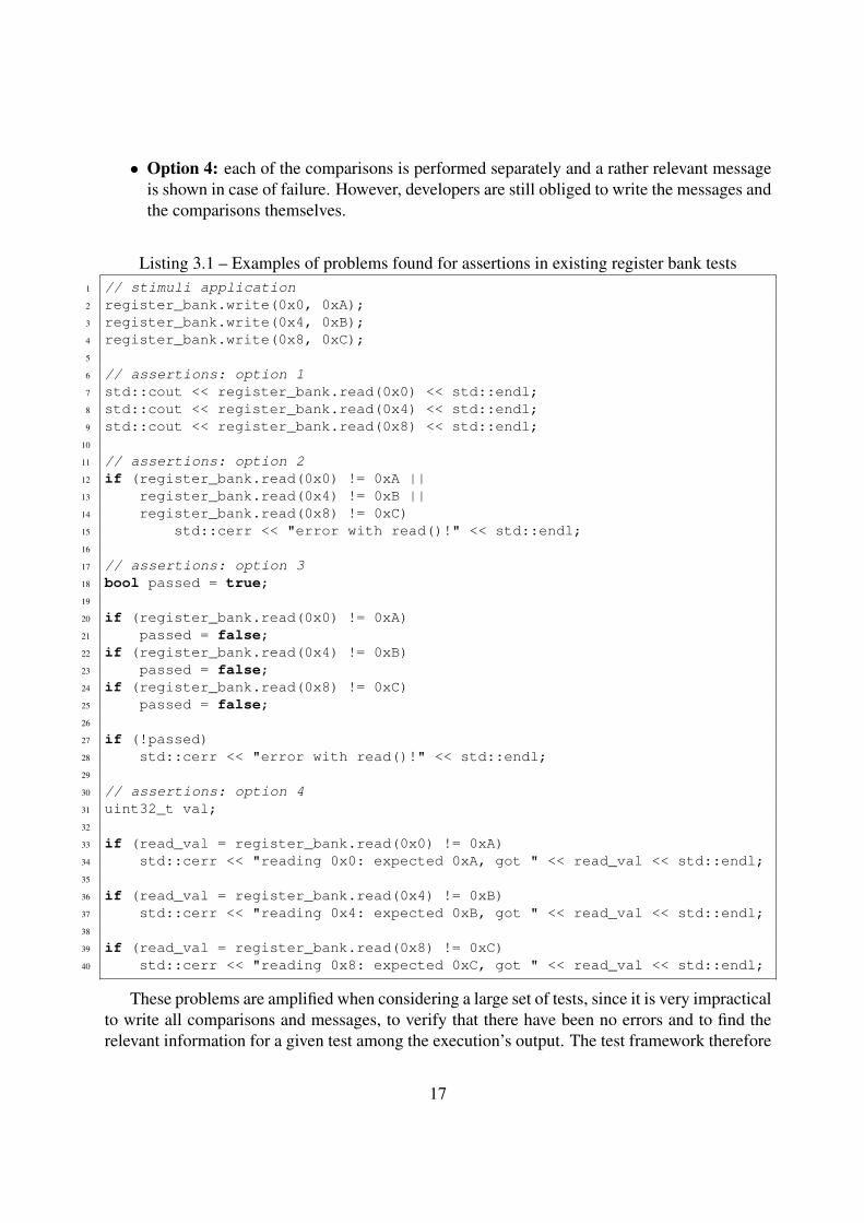
• Option 4: each of the comparisons is performed separately and a rather relevant messageis shown in case of failure. However, developers are still obliged to write the messages andthe comparisons themselves.
Listing 3.1 – Examples of problems found for assertions in existing register bank tests1 // stimuli application2 register_bank.write(0x0, 0xA);3 register_bank.write(0x4, 0xB);4 register_bank.write(0x8, 0xC);5
6 // assertions: option 17 std::cout << register_bank.read(0x0) << std::endl;8 std::cout << register_bank.read(0x4) << std::endl;9 std::cout << register_bank.read(0x8) << std::endl;
10
11 // assertions: option 212 if (register_bank.read(0x0) != 0xA ||13 register_bank.read(0x4) != 0xB ||14 register_bank.read(0x8) != 0xC)15 std::cerr << "error with read()!" << std::endl;16
17 // assertions: option 318 bool passed = true;19
20 if (register_bank.read(0x0) != 0xA)21 passed = false;22 if (register_bank.read(0x4) != 0xB)23 passed = false;24 if (register_bank.read(0x8) != 0xC)25 passed = false;26
27 if (!passed)28 std::cerr << "error with read()!" << std::endl;29
30 // assertions: option 431 uint32_t val;32
33 if (read_val = register_bank.read(0x0) != 0xA)34 std::cerr << "reading 0x0: expected 0xA, got " << read_val << std::endl;35
36 if (read_val = register_bank.read(0x4) != 0xB)37 std::cerr << "reading 0x4: expected 0xB, got " << read_val << std::endl;38
39 if (read_val = register_bank.read(0x8) != 0xC)40 std::cerr << "reading 0x8: expected 0xC, got " << read_val << std::endl;
These problems are amplified when considering a large set of tests, since it is very impracticalto write all comparisons and messages, to verify that there have been no errors and to find therelevant information for a given test among the execution’s output. The test framework therefore
17
should provide the user a simple interface that facilitates the performing of asssertions. It shoulddo so for all the necessary data types (not only for the primitive ones but also for the model’sobjects). Moreover, it is important to allow the tester to specify whether the failure of an assertionis fatal, that is, if the current test case should be aborted or continued if a value is not as expected.
Message assertions
A specific type of assertion which should also be supported is that of expecting messages from themodel (for instance, an error message when an invalid operation is carried out). Within the SLMteam, all SystemC models make use of the tlm_message development kit, which provideshomogeneous instrumentation capabilities, such as info, error, warning and debug messages.The framework needs to communicate with it in order to obtain the required information aboutthe messages generated by the tested objects.
Tests structure
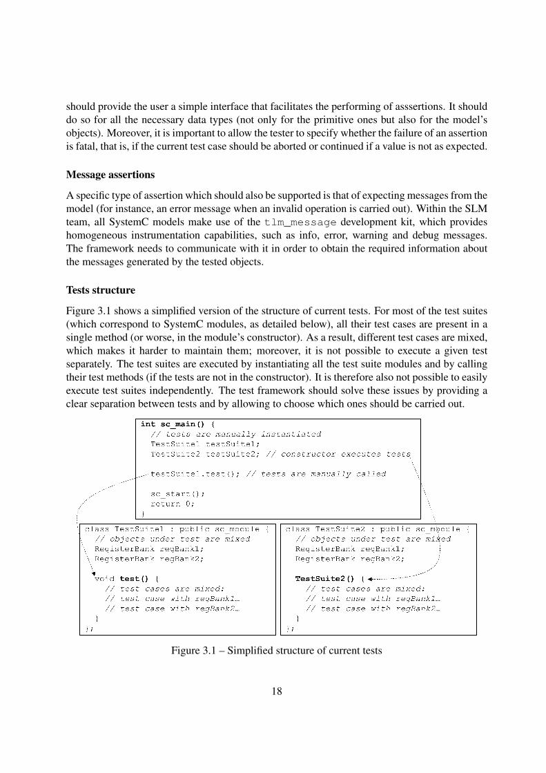
Figure 3.1 shows a simplified version of the structure of current tests. For most of the test suites(which correspond to SystemC modules, as detailed below), all their test cases are present in asingle method (or worse, in the module’s constructor). As a result, different test cases are mixed,which makes it harder to maintain them; moreover, it is not possible to execute a given testseparately. The test suites are executed by instantiating all the test suite modules and by callingtheir test methods (if the tests are not in the constructor). It is therefore also not possible to easilyexecute test suites independently. The test framework should solve these issues by providing aclear separation between tests and by allowing to choose which ones should be carried out.
Figure 3.1 – Simplified structure of current tests
18
Instantiation of the module under test
When testing an object, it is rather reasonable to say that one or more instances of it will berequired. The particularity here is that the register bank and most other base elements must beinstantiated within a SystemC module. The current solution is to have one SystemC module foreach test suite. This modules contains the required number of objects to test as attributes. As aresult, the objects tested by each of the test cases for a given feature are mixed, also impactingthe independence of test cases. The test framework should provide a simple way of declaring theobject under test and of instantiating it for each of the test cases.
Construction and simulation
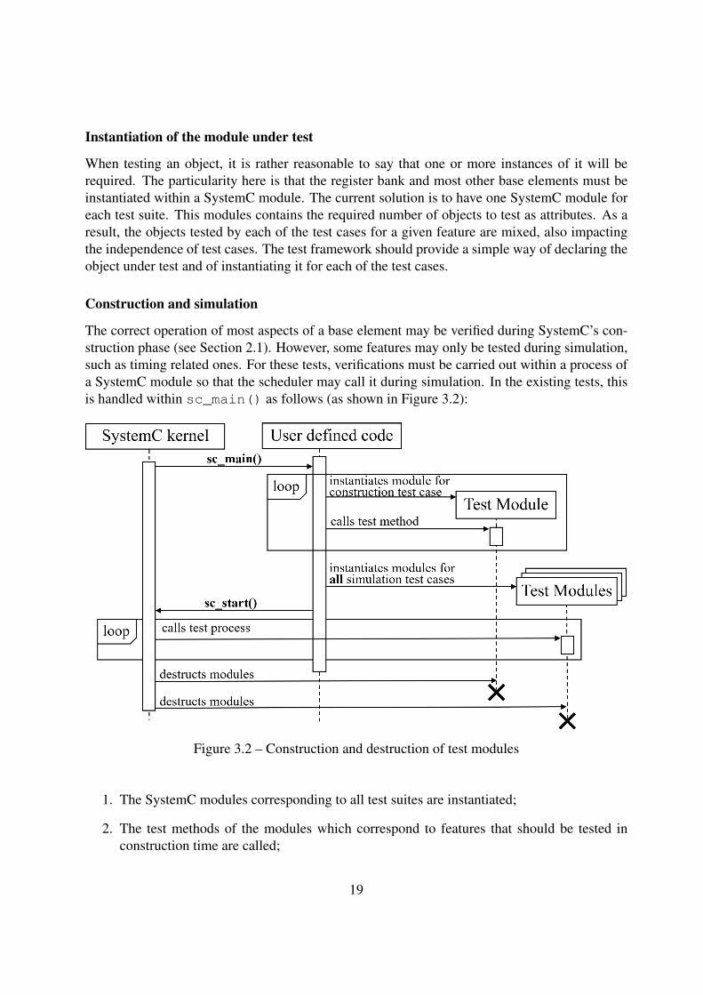
The correct operation of most aspects of a base element may be verified during SystemC’s con-struction phase (see Section 2.1). However, some features may only be tested during simulation,such as timing related ones. For these tests, verifications must be carried out within a process ofa SystemC module so that the scheduler may call it during simulation. In the existing tests, thisis handled within sc_main() as follows (as shown in Figure 3.2):
Figure 3.2 – Construction and destruction of test modules
1. The SystemC modules corresponding to all test suites are instantiated;
2. The test methods of the modules which correspond to features that should be tested inconstruction time are called;
19
3. Simulation is started and SystemC’s scheduler calls the test processes of the modules cor-responding to features that should be tested in simulation time;
4. After the end of simulation, all modules are destructed.
This method respects the lifetime constraints of SystemC objects. However, it is not achievedsystematically, that is, the instantiation and destruction of modules and the calls to their methodsare manually carried out. In order to avoid errors, this behavior should be handled by the testframework, and not by the actual tests. The solution should provide a manner of identifyingwhich test should be executed during construction or simulation. Moreover, it should handle theinstantiation and destruction of SystemC objects accordingly.
Temporal isolation of simulation tests
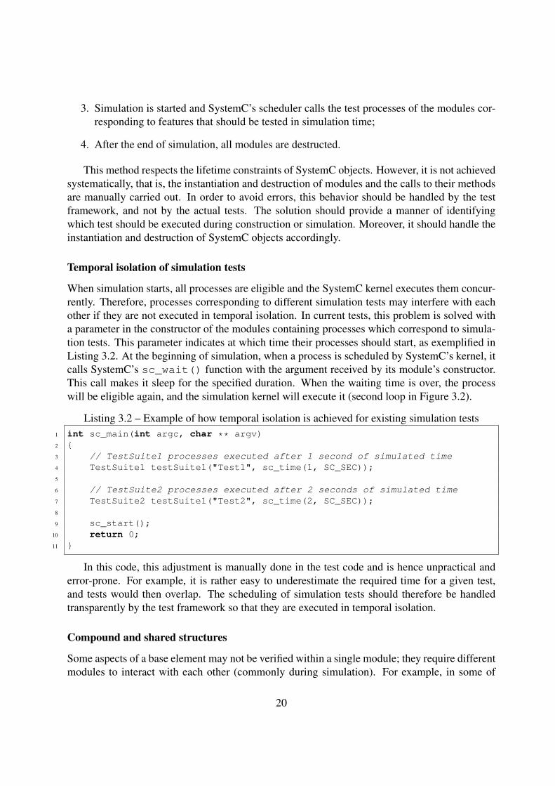
When simulation starts, all processes are eligible and the SystemC kernel executes them concur-rently. Therefore, processes corresponding to different simulation tests may interfere with eachother if they are not executed in temporal isolation. In current tests, this problem is solved witha parameter in the constructor of the modules containing processes which correspond to simula-tion tests. This parameter indicates at which time their processes should start, as exemplified inListing 3.2. At the beginning of simulation, when a process is scheduled by SystemC’s kernel, itcalls SystemC’s sc_wait() function with the argument received by its module’s constructor.This call makes it sleep for the specified duration. When the waiting time is over, the processwill be eligible again, and the simulation kernel will execute it (second loop in Figure 3.2).
Listing 3.2 – Example of how temporal isolation is achieved for existing simulation tests1 int sc_main(int argc, char ** argv)2 {3 // TestSuite1 processes executed after 1 second of simulated time4 TestSuite1 testSuite1("Test1", sc_time(1, SC_SEC));5
6 // TestSuite2 processes executed after 2 seconds of simulated time7 TestSuite2 testSuite1("Test2", sc_time(2, SC_SEC));8
9 sc_start();10 return 0;11 }
In this code, this adjustment is manually done in the test code and is hence unpractical anderror-prone. For example, it is rather easy to underestimate the required time for a given test,and tests would then overlap. The scheduling of simulation tests should therefore be handledtransparently by the test framework so that they are executed in temporal isolation.
Compound and shared structures
Some aspects of a base element may not be verified within a single module; they require differentmodules to interact with each other (commonly during simulation). For example, in some of
20
the register bank tests, a separate modules needs to interact with the module which actuallycontains the register bank. The test framework should also cover this possibility and provide itsusers a way of describing the required structures for their tests. Moreover, different test casesmay require the same structure, and in most cases, each of them requires a separate instance.However, for some structures needed by multiple tests cases, it is too expensive (memory-wise,for example) to instantiate them many times. The test cases must share a single instance of it andreset it to the inital condition after the execution of the required operations so that the remainingtest cases may start from a known state. The framework should therefore also provide a mannerof sharing the same instance of such a structure among many test cases.
Reporting of results
The tests’ results take the form of textual information which describes which tests were carriedout and which succeeded. Clear and well-organized test reports are paramount to verify thata modification has not introduced regressions and to find the problem if it did. In the existingtests, the reporting of assertion results is not homogeneous. Moreover, even though the assertionresults from different test cases and test suites are separated by headers which indicate whichtest is being executed, this output is constructed manually in the test code. Since this coderepetition could lead to errors, the reporting of results should be a responsibility of the testframework. It should generate adequate result messages for the assertions and provide a simpleway of describing what is being verified by each test case. This information should then beassembled in an adequate and well-structured format. This could be achieved with the aid of thetlm_message instrumentation library.
21
4. Analysis of existing test frameworks
Some open-source testing frameworks are analyzed in order to not only verify their applica-bility regarding the already defined requirements but also to identify new ones. Frameworkscorresponding to two different testing methods are considered: behavior-driven development1, arather modern technique in which tests are based on a textual description of the software’s fea-tures, and unit testing, a classical approach for the test of software. Based on these analyses, adecision about whether to directly use these solutions is made. Moreover, the definitive list of therequirements and constraints to be taken into account for the development of the test frameworkis established.
4.1 Behavior Driven Development frameworkInitially, the methodology itself is revised. Next, an existing open-source BDD framework ischosen and thoroughly studied in order to well understand whether it satisfies the previouslyestablished requirements. For the same reason, some existing tests for the register bank brickare rewritten with the chosen BDD framework. As a result of this analysis, we show that somerequirements could not be satisfied. An attempt to modify the framework in order to solve theseissues is presented and analyzed. Finally, based on the results of this study, a choice of whetherto proceed with the use of BDD for the testing of SystemC base elements is made.
4.1.1 The BDD methodologyBehavior-driven development is a software development methodology whose main principle is todescribe the software’s expected behavior before its implementation. This description is writtenin a semi-formal format which uses natural language constructs and may therefore be sharedbetween developers and non-technical personnel. The most commonly used format is a domainspecific language which is very similar to user stories [9]. This behavioral description servesnot only as specification but also as tests definition [10]. The tests are carried out with the aidof a BDD support tool which takes this description as input and executes the code associatedwith each sentence or clause (this association is defined by developers for each project). Sincethe tests are written before implementation, BDD is commonly considered an extension of test-driven development (TDD)2.
1Even though this methodology is usually employed in levels of testing which are higher than that of the consid-ered SystemC bricks (e.g. system testing), it is studied nonetheless due to the complexity of the tested objects.
2Test-driven development is a methodology which essentially states that for each feature of a software unit, asoftware developer must first define a test set for the feature, then implement it, and finally verify that the imple-mentation makes the tests succeed.
22
The BDD methodology concurs with the test factorization effort addressed by this project.A simple and homogeneous way of specifying the SystemC bricks’ behavior and a method ofdirectly obtaining their tests from this description would certainly increase the quality of tests.Even though the software which would be tested by the framework to be developed alreadyexists, a test framework based on BDD could still be suitable for it. Moreover, the frameworkcould be used with total compliance to BDD for the specification of new features for a baseelement before their implementations.
4.1.2 The Cucumber frameworkThe analyzed behavior-driven development test framework is called Cucumber [11]. It was se-lected between other options as it is one of the most widely used BDD frameworks, with morethan 100,000 downloads per week and more than a thousand contributors. Moreover, even thoughCucumber was originally conceived with and for the Ruby programming language [12], it sup-ports many other ones such as C++, which makes it more suitable to use with SystemC.
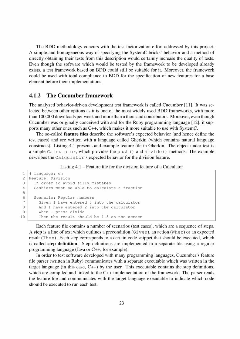
The so-called feature files describe the software’s expected behavior (and hence define thetest cases) and are written with a language called Gherkin (which contains natural languageconstructs). Listing 4.1 presents and example feature file in Gherkin. The object under test isa simple Calculator, which provides the push() and divide() methods. The exampledescribes the Calculator’s expected behavior for the division feature.
Listing 4.1 – Feature file for the division feature of a Calculator1 # language: en2 Feature: Division3 In order to avoid silly mistakes4 Cashiers must be able to calculate a fraction56 Scenario: Regular numbers7 Given I have entered 3 into the calculator8 And I have entered 2 into the calculator9 When I press divide
10 Then the result should be 1.5 on the screen
Each feature file contains a number of scenarios (test cases), which are a sequence of steps.A step is a line of text which outlines a precondition (Given), an action (When) or an expectedresult (Then). Each step corresponds to a certain code snippet that should be executed, whichis called step definition. Step definitions are implemented in a separate file using a regularprogramming language (Java or C++, for example).
In order to test software developed with many programming languages, Cucumber’s featurefile parser (written in Ruby) communicates with a separate executable which was written in thetarget language (in this case, C++) by the user. This executable contains the step definitions,which are compiled and linked to the C++ implementation of the framework. The parser readsthe feature file and communicates with the target language executable to indicate which codeshould be executed to run each test.
23
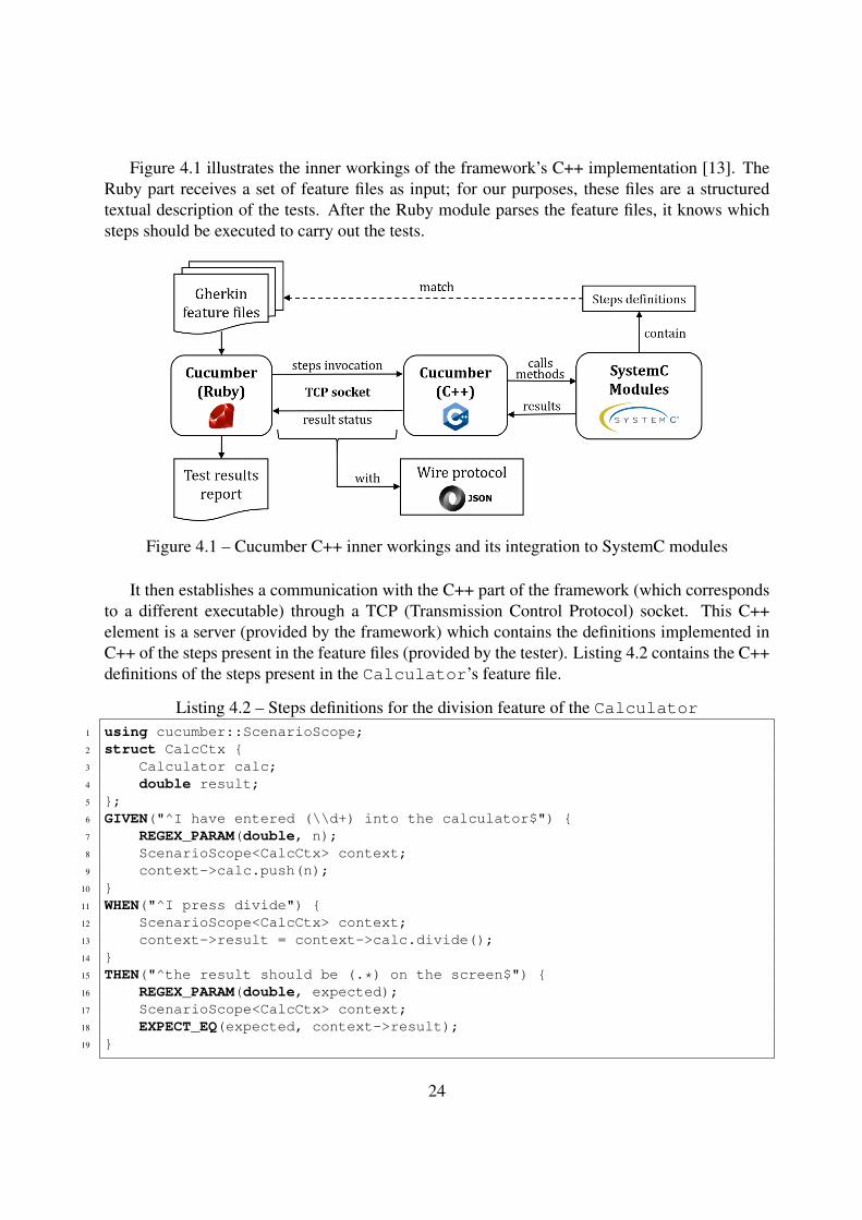
Figure 4.1 illustrates the inner workings of the framework’s C++ implementation [13]. TheRuby part receives a set of feature files as input; for our purposes, these files are a structuredtextual description of the tests. After the Ruby module parses the feature files, it knows whichsteps should be executed to carry out the tests.
Figure 4.1 – Cucumber C++ inner workings and its integration to SystemC modules
It then establishes a communication with the C++ part of the framework (which correspondsto a different executable) through a TCP (Transmission Control Protocol) socket. This C++element is a server (provided by the framework) which contains the definitions implemented inC++ of the steps present in the feature files (provided by the tester). Listing 4.2 contains the C++definitions of the steps present in the Calculator’s feature file.
Listing 4.2 – Steps definitions for the division feature of the Calculator1 using cucumber::ScenarioScope;2 struct CalcCtx {3 Calculator calc;4 double result;5 };6 GIVEN("^I have entered (\\d+) into the calculator$") {7 REGEX_PARAM(double, n);8 ScenarioScope<CalcCtx> context;9 context->calc.push(n);
10 }11 WHEN("^I press divide") {12 ScenarioScope<CalcCtx> context;13 context->result = context->calc.divide();14 }15 THEN("^the result should be (.*) on the screen$") {16 REGEX_PARAM(double, expected);17 ScenarioScope<CalcCtx> context;18 EXPECT_EQ(expected, context->result);19 }
24
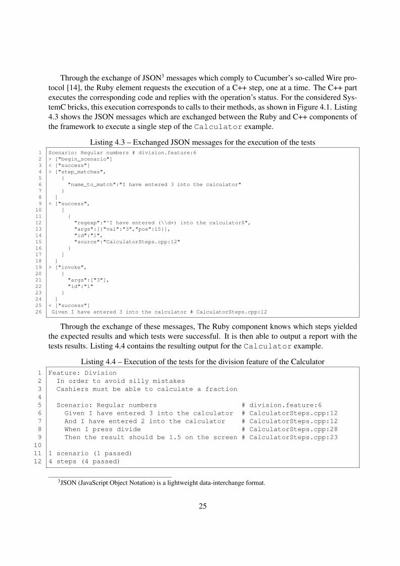
Through the exchange of JSON3 messages which comply to Cucumber’s so-called Wire pro-tocol [14], the Ruby element requests the execution of a C++ step, one at a time. The C++ partexecutes the corresponding code and replies with the operation’s status. For the considered Sys-temC bricks, this execution corresponds to calls to their methods, as shown in Figure 4.1. Listing4.3 shows the JSON messages which are exchanged between the Ruby and C++ components ofthe framework to execute a single step of the Calculator example.
Listing 4.3 – Exchanged JSON messages for the execution of the tests1 Scenario: Regular numbers # division.feature:62 > ["begin_scenario"]3 < ["success"]4 > ["step_matches",5 {6 "name_to_match":"I have entered 3 into the calculator"7 }8 ]9 < ["success",10 [11 {12 "regexp":"^I have entered (\\d+) into the calculator$",13 "args":[{"val":"3","pos":15}],14 "id":"1",15 "source":"CalculatorSteps.cpp:12"16 }17 ]18 ]19 > ["invoke",20 {21 "args":["3"],22 "id":"1"23 }24 ]25 < ["success"]26 Given I have entered 3 into the calculator # CalculatorSteps.cpp:12
Through the exchange of these messages, The Ruby component knows which steps yieldedthe expected results and which tests were successful. It is then able to output a report with thetests results. Listing 4.4 contains the resulting output for the Calculator example.
Listing 4.4 – Execution of the tests for the division feature of the Calculator1 Feature: Division2 In order to avoid silly mistakes3 Cashiers must be able to calculate a fraction45 Scenario: Regular numbers # division.feature:66 Given I have entered 3 into the calculator # CalculatorSteps.cpp:127 And I have entered 2 into the calculator # CalculatorSteps.cpp:128 When I press divide # CalculatorSteps.cpp:289 Then the result should be 1.5 on the screen # CalculatorSteps.cpp:23
1011 1 scenario (1 passed)12 4 steps (4 passed)
3JSON (JavaScript Object Notation) is a lightweight data-interchange format.
25
4.1.3 Adapting Cucumber to SystemCIn order to use the Cucumber C++ framework to test SystemC bricks, it is necessary to integrateit to the SLM team’s development environment. The framework’s compilation differs accordingto the used compiler and target operating system; moreover, it is also necessary to build itsdependencies for each of these options. This is possibly a constraint for the utilization of theframework for the testing of SystemC bricks since all environments supported by the team wouldhave to be considered, as explained in Section 3.1.
Nonetheless, in order to further study the suitability of the framework, it is integrated to oneof the supported environments. Next, a part of one of the register bank’s test suites is rewritten inthe form of a feature file. A SystemC module containing the corresponding steps definitions andinstantiating the Cucumber server is built. The tests corresponding to this feature file are thenexecuted. Even though they are successful, a few complications become clear:
• No simulation tests: the successfully rewritten tests are executed during SystemC’s con-struction time. Writing tests that require simulation with Cucumber is much more com-plicated. In order to start the simulation, sc_start() must be called during the testsexecution. However, the function that starts Cucumber’s C++ server is called withinsc_main() and it only returns after all tests have been carried out. The call to thefunction sc_start() must therefore be made within a scenario; nonetheless, since Cu-cumber does not guarantee an order of execution for the tests, it is not possible to do so, asconstruction tests must be carried out before simulation ones. The fact that sc_moduleobjects required by all scenarios must be instantiated before the beginning of simulation isa problem for the same reason. Consequently, Cucumber does not support the writing oftests that require simulation.
• Fatal failures: if a test scenario fails in a manner considered fatal by SystemC, the C++executable quits, and the Ruby component driving the tests execution is not be able tocontinue with the next scenario as it should. This problem may be solved to some extentthrough the modification of Cucumber’s Wire protocol; nonetheless, maintaining a mod-ified version of the framework would encumber even further the support of the requiredenvironments.
• Compound and shared structures: the rather rigid structure of Cucumber’s step defini-tions makes it difficult to write complex tests which require compound structures. More-over, there is no simple way of sharing an instance of an expensive object between manyscenarios.
• Base elements operations: in order to test a SystemC brick with Cucumber, it is necessaryto write one or more step definitions for each of the operations that may be carried outwith it (most commonly, method calls). The initial idea was to provide and maintain thesedefinitions for the base elements in order to accelerate the writing of tests. However, theinterface of most base elements is rather extensive (i.e. the underlying objects providea large number of methods) and changes rather frequently. When steps are not repeated
26
a considerable amount of times, one may conclude that the advantages brought by themethodology do not justify the overhead of linking each step to its definition. With regardto this aspect, BDD is therefore somewhat inadequate for the testing of SystemC bricks.It could, however, be more suitable for the testing of components, whose interfaces aregenerally simpler and more repetitive (e.g. read and write operations when connected to acommunication bus).
4.1.4 Conclusions about BDD approachAfter the analysis of Cucumber’s inner working and the rewriting of some existing tests, severalproblems regarding its usage to test the SystemC bricks developed by the SLM team becameclear, notably:
• the difficulty of integrating and maintaining the framework and its dependencies for eachof the supported environments;
• the inadequacy of having to write and maintain step definitions for each of the many baseelements’ operations;
• the impossibility of executing tests during simulation;
• the complication of maintaining a modified version to support SystemC fatal failures;
• the difficulty to declare and share complex structures between tests.
It is therefore clear that Cucumber should not be directly used for the testing of SystemCbricks and that a more classical approach is to be considered. Nonetheless, a BDD frameworkwhich respects the SystemC and maintenance constraints above could very well be suitable forthe testing of components – such a tool could be possibly developed in a future project, forexample.
4.2 C++ unit testing solutionsAmongst the multitude of available C++ open-source unit testing frameworks, two of them arestudied in order to better understand the practices of existing unit testing solutions. Their featuresare analyzed ir order to understand their suitableness with regard to the identified requirements.Next, some example existing tests are reimplemented with these frameworks to verify their ap-plicability. As a result of this analysis, common features for this kind of tool are identified;moreover, an informed decision about whether to directly use them for the testing of SystemCbricks is made.
27
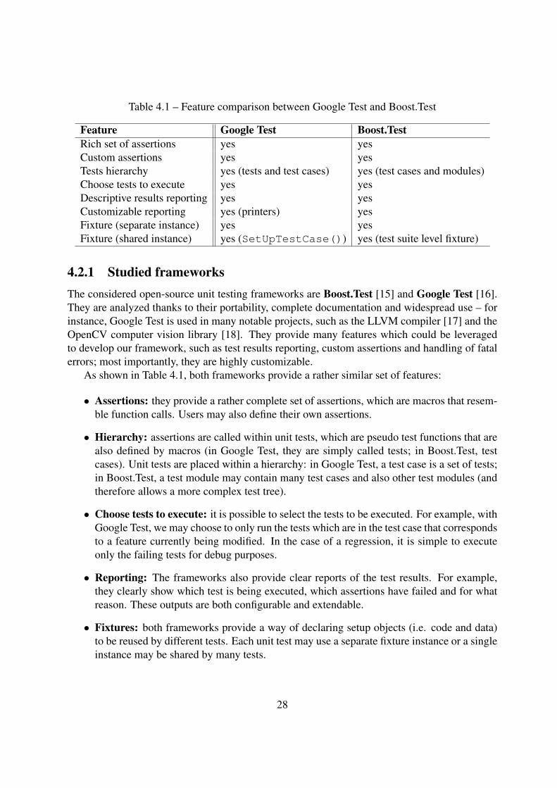
Table 4.1 – Feature comparison between Google Test and Boost.Test
Feature Google Test Boost.TestRich set of assertions yes yesCustom assertions yes yesTests hierarchy yes (tests and test cases) yes (test cases and modules)Choose tests to execute yes yesDescriptive results reporting yes yesCustomizable reporting yes (printers) yesFixture (separate instance) yes yesFixture (shared instance) yes (SetUpTestCase()) yes (test suite level fixture)
4.2.1 Studied frameworksThe considered open-source unit testing frameworks are Boost.Test [15] and Google Test [16].They are analyzed thanks to their portability, complete documentation and widespread use – forinstance, Google Test is used in many notable projects, such as the LLVM compiler [17] and theOpenCV computer vision library [18]. They provide many features which could be leveragedto develop our framework, such as test results reporting, custom assertions and handling of fatalerrors; most importantly, they are highly customizable.
As shown in Table 4.1, both frameworks provide a rather similar set of features:
• Assertions: they provide a rather complete set of assertions, which are macros that resem-ble function calls. Users may also define their own assertions.
• Hierarchy: assertions are called within unit tests, which are pseudo test functions that arealso defined by macros (in Google Test, they are simply called tests; in Boost.Test, testcases). Unit tests are placed within a hierarchy: in Google Test, a test case is a set of tests;in Boost.Test, a test module may contain many test cases and also other test modules (andtherefore allows a more complex test tree).
• Choose tests to execute: it is possible to select the tests to be executed. For example, withGoogle Test, we may choose to only run the tests which are in the test case that correspondsto a feature currently being modified. In the case of a regression, it is simple to executeonly the failing tests for debug purposes.
• Reporting: The frameworks also provide clear reports of the test results. For example,they clearly show which test is being executed, which assertions have failed and for whatreason. These outputs are both configurable and extendable.
• Fixtures: both frameworks provide a way of declaring setup objects (i.e. code and data)to be reused by different tests. Each unit test may use a separate fixture instance or a singleinstance may be shared by many tests.
28
4.2.2 Tests reimplementationBoth of the studied unit testing frameworks are integrated to one of the environments supportedby the SLM team. Some of the existing tests for the register bank brick are then rewritten withboth of them. Even though a few simple cases are successfully developed, some conflicts withpreviously defined constraints arise:
• Lifetime of SystemC objects: when reusing a fixture object for many tests, the frame-works makes an instance of it at the start of each unit test and destructs it when the testis over. In order to test SystemC bricks, most of these fixtures are or contain SystemCrelated objects (notably modules). As explained in Section 2.1, after being instantiated,these objects may only be destructed after the end of simulation.
• Simulation: in both frameworks, the invokation of tests is carried out with a function callwhich only returns after all tests have been executed. The call to sc_start() for thetests that should be carried out during SystemC simulation must therefore be done by oneof the tests. Since tests are independent and there is no guaranteed order of execution, it isnot possible to divide construction and simulation tests by simply using these frameworksout of the box. Even if this division were possible, all SystemC objects required by the testswould have to be instantiated before the start of simulation. As explained in the previousproblem, the frameworks instantiate them on demand for each of the tests.
• Modification and maintenance: the problems above could possibly be solved by modify-ing the framework; however, after a brief analysis of their implementations, it is clear thatthis task would be far away from trivial. Moreover, maintaining such a modified version(either to correct bugs or to add features) would be a rather cumbersome responsibility,since it would require not only having good knowledge of both the original framework andthe modifications that were made, but also handling it for all the supported environments.
4.2.3 ConclusionAfter the analysis of both unit testing frameworks, many features that would be interesting forthe testing of SystemC bricks have been identified. However, some of the constraints imposedby SystemC conflict with them and hence limit their off-the-shelf usage. Since it would becomplicated to maintain a highly modified version of one of these frameworks, one may concludethat the studied solutions should not be used for the testing of SystemC bricks.
4.3 ResultsThe first result of the performed analyses is the identification of the requirements to be respectedby the solution to be developed. They are summarized in Table 4.2, which also shows whetherthe studied frameworks satisfy each one of them.
The second result is the conclusion that the studied frameworks should not be used for thetesting of SystemC bricks, as they do not satisfy some of the established requirements. Therefore,
29
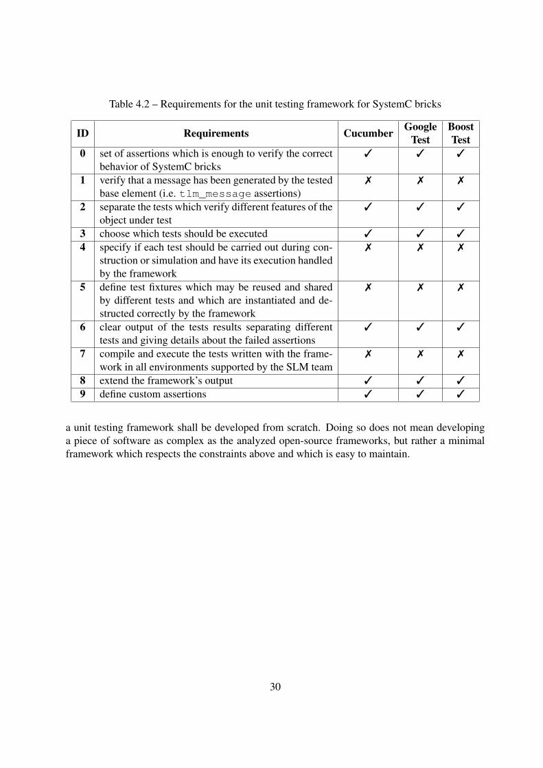
Table 4.2 – Requirements for the unit testing framework for SystemC bricks
ID Requirements Cucumber GoogleTest
BoostTest
0 set of assertions which is enough to verify the correctbehavior of SystemC bricks
3 3 3
1 verify that a message has been generated by the testedbase element (i.e. tlm_message assertions)
7 7 7
2 separate the tests which verify different features of theobject under test
3 3 3
3 choose which tests should be executed 3 3 3
4 specify if each test should be carried out during con-struction or simulation and have its execution handledby the framework
7 7 7
5 define test fixtures which may be reused and sharedby different tests and which are instantiated and de-structed correctly by the framework
7 7 7
6 clear output of the tests results separating differenttests and giving details about the failed assertions
3 3 3
7 compile and execute the tests written with the frame-work in all environments supported by the SLM team
7 7 7
8 extend the framework’s output 3 3 3
9 define custom assertions 3 3 3
a unit testing framework shall be developed from scratch. Doing so does not mean developinga piece of software as complex as the analyzed open-source frameworks, but rather a minimalframework which respects the constraints above and which is easy to maintain.
30
5. Proposed unit testing framework forSystemC
Based on the results of the analysis presented in Chapter 4, the first step of the developmentof the testing framework for reusable SystemC bricks (henceforward called SystemC-Unit) isto establish a list of features whose objective is to satisfy the defined requirements. An initialarchitecture is then devised and its implementation is described. The development of the archi-tecture and the implementation was performed incrementally with the addition of the additionalfeatures1. Some validation exercises are carried out with the framework’s future users, whichallow the identification of a few missing features and the verification that the developed solutionmeets its users’ needs. The testing of the framework is also described.
5.1 FeaturesThe following list of features fulfills the established requirements for SystemC-Unit:
• Assertions: the framework provides a set of assertions, which are function-like macros thatallows its user to specify the expected behavior for the objects being tested. For example,with the equality assertion, it is possible to compare the return value of a tested object’smethod to the expected value. In order to specify whether the current test should continueif an assertion fail, each one of them has both fatal and non-fatal variants. The frameworkhandles the identification of which tests failed or not according to their assertions and thesystematic printing of the assertions results (Requirement 0).
– Custom assertions: since it is impossible to anticipate all the assertions users willneed, the framework provides a way of defining new assertions (Requirement 9).
• tlm_message assertions: as aforementioned, the SystemC bricks to be tested make useof the tlm_message devkit for instrumentation purposes, that is, the printing of mes-sages with different types. The framework provides a manner of asserting that, for a givenoperation, a given message with a given type is generated. Moreover, the devkit allowserror messages to be fatal and the execution of the program is hence aborted; this behav-ior is detected but bypassed by SystemC-Unit so that the remaining tests may continue(Requirement 1).
• Test structure: tests defined with the framework are organized into the hierarchized struc-ture (Requirement 2) shown in Figure 5.1, which is as follows:
1For simplicity’s sake, only the final list of features and architecture are presented in this report.
31
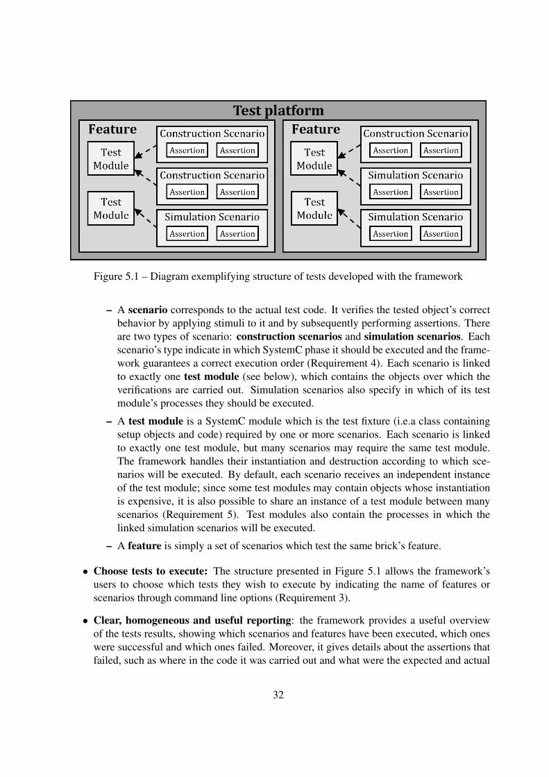
Figure 5.1 – Diagram exemplifying structure of tests developed with the framework
– A scenario corresponds to the actual test code. It verifies the tested object’s correctbehavior by applying stimuli to it and by subsequently performing assertions. Thereare two types of scenario: construction scenarios and simulation scenarios. Eachscenario’s type indicate in which SystemC phase it should be executed and the frame-work guarantees a correct execution order (Requirement 4). Each scenario is linkedto exactly one test module (see below), which contains the objects over which theverifications are carried out. Simulation scenarios also specify in which of its testmodule’s processes they should be executed.
– A test module is a SystemC module which is the test fixture (i.e.a class containingsetup objects and code) required by one or more scenarios. Each scenario is linkedto exactly one test module, but many scenarios may require the same test module.The framework handles their instantiation and destruction according to which sce-narios will be executed. By default, each scenario receives an independent instanceof the test module; since some test modules may contain objects whose instantiationis expensive, it is also possible to share an instance of a test module between manyscenarios (Requirement 5). Test modules also contain the processes in which thelinked simulation scenarios will be executed.
– A feature is simply a set of scenarios which test the same brick’s feature.
• Choose tests to execute: The structure presented in Figure 5.1 allows the framework’susers to choose which tests they wish to execute by indicating the name of features orscenarios through command line options (Requirement 3).
• Clear, homogeneous and useful reporting: the framework provides a useful overviewof the tests results, showing which scenarios and features have been executed, which oneswere successful and which ones failed. Moreover, it gives details about the assertions thatfailed, such as where in the code it was carried out and what were the expected and actual
32
results (Requirement 6). The default output is somewhat light, since the most commonobjective of the tests’ execution is simply to check that there have been no regressions. Amore verbose output is also available and may be enabled with a command line option.
– Extendable reporting: The default output may be replaced or extended with the ad-dition of a user-provided object, which must implement the printer interface definedby the framework (Requirement 8). For instance, this feature may be used to generatea PDF or XML document with the tests results.
5.2 Implementation overviewThe framework’s architecture is mainly divided in four packages:
• Core: the framework’s main entry point, it handles its configuration (e.g. choice of teststo execute) and extension (e.g. addition of a printer) by the user and the tests execution;
• Assertions: defines the classes corresponding to the different assertion types the users maycarry out, as well as the class from which they should inherit in order to define their own;
• Structure: defines the classes from which the users should inherit in order to define theirtests and handles their registration with the framework’s core.
• Printing: defines the interface expected from printer objects, provides its default im-plementation (which generates the output with the tests results) and handles the existingprinter objects.
Figure 5.2 represents the interactions between the framework’s packages and the user-definedtests for a typical execution of tests, which goes as follows (the numbers below correspond tothose of the figure):
1. The user develops tests by writing classes with inherit from classes provided by the frame-work;
2. When the execution starts, the user-defined tests statically self-register with the frame-work’s core;
3. The user calls the framework’s initialization and the core parses the user’s command-lineoptions (for example, indicating that a single test case should be executed and specifyingwhich one);
4. The framework’s core iterates over the tests hierarchy and the tests chosen by the user areexecuted (first, all construction scenarios, and then, the simulations ones):
(a) Construction scenarios: the required test modules are instantiated on-demand and thetest method is called;
33
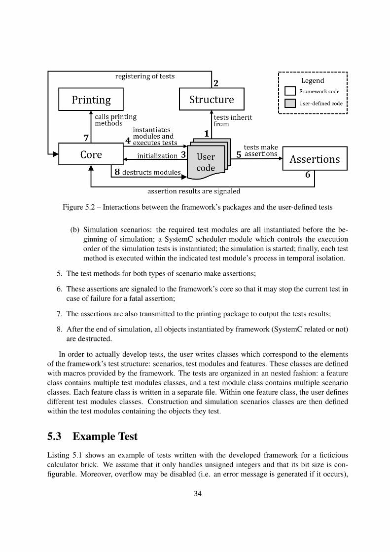
Figure 5.2 – Interactions between the framework’s packages and the user-defined tests
(b) Simulation scenarios: the required test modules are all instantiated before the be-ginning of simulation; a SystemC scheduler module which controls the executionorder of the simulation tests is instantiated; the simulation is started; finally, each testmethod is executed within the indicated test module’s process in temporal isolation.
5. The test methods for both types of scenario make assertions;
6. These assertions are signaled to the framework’s core so that it may stop the current test incase of failure for a fatal assertion;
7. The assertions are also transmitted to the printing package to output the tests results;
8. After the end of simulation, all objects instantiated by framework (SystemC related or not)are destructed.
In order to actually develop tests, the user writes classes which correspond to the elementsof the framework’s test structure: scenarios, test modules and features. These classes are definedwith macros provided by the framework. The tests are organized in an nested fashion: a featureclass contains multiple test modules classes, and a test module class contains multiple scenarioclasses. Each feature class is written in a separate file. Within one feature class, the user definesdifferent test modules classes. Construction and simulation scenarios classes are then definedwithin the test modules containing the objects they test.
5.3 Example TestListing 5.1 shows an example of tests written with the developed framework for a ficticiouscalculator brick. We assume that it only handles unsigned integers and that its bit size is con-figurable. Moreover, overflow may be disabled (i.e. an error message is generated if it occurs),
34
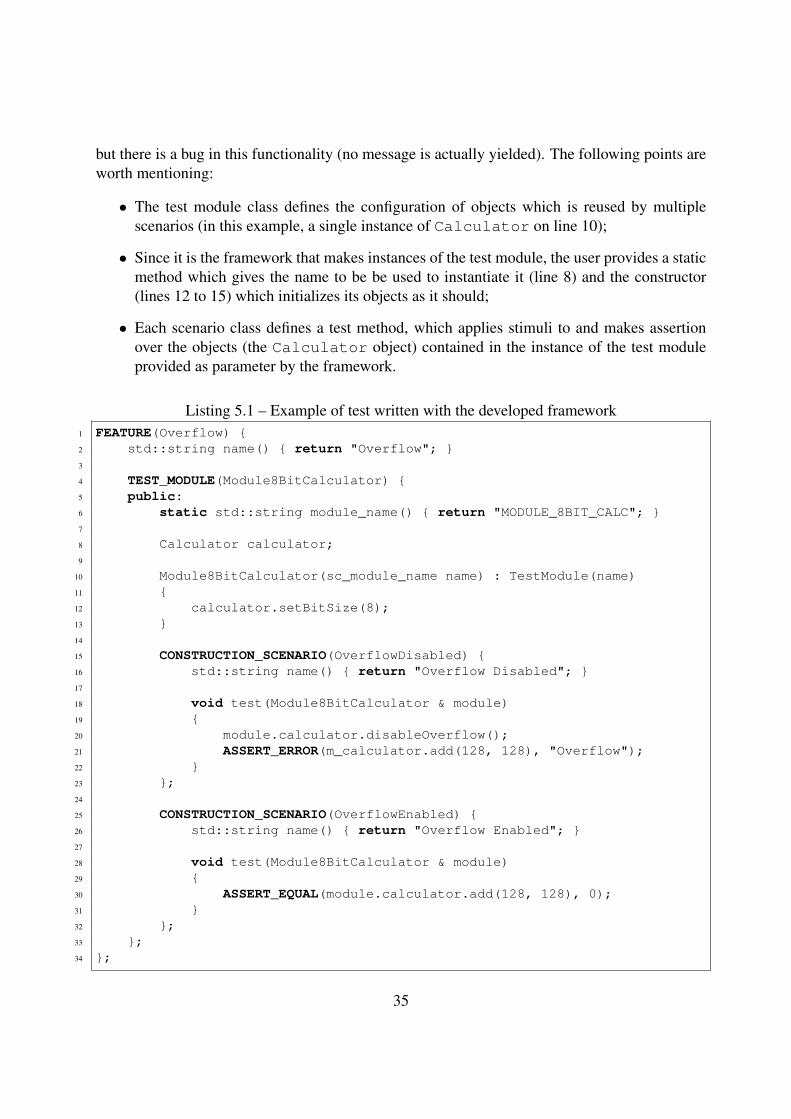
but there is a bug in this functionality (no message is actually yielded). The following points areworth mentioning:
• The test module class defines the configuration of objects which is reused by multiplescenarios (in this example, a single instance of Calculator on line 10);
• Since it is the framework that makes instances of the test module, the user provides a staticmethod which gives the name to be be used to instantiate it (line 8) and the constructor(lines 12 to 15) which initializes its objects as it should;
• Each scenario class defines a test method, which applies stimuli to and makes assertionover the objects (the Calculator object) contained in the instance of the test moduleprovided as parameter by the framework.
Listing 5.1 – Example of test written with the developed framework1 FEATURE(Overflow) {2 std::string name() { return "Overflow"; }3
4 TEST_MODULE(Module8BitCalculator) {5 public:6 static std::string module_name() { return "MODULE_8BIT_CALC"; }7
8 Calculator calculator;9
10 Module8BitCalculator(sc_module_name name) : TestModule(name)11 {12 calculator.setBitSize(8);13 }14
15 CONSTRUCTION_SCENARIO(OverflowDisabled) {16 std::string name() { return "Overflow Disabled"; }17
18 void test(Module8BitCalculator & module)19 {20 module.calculator.disableOverflow();21 ASSERT_ERROR(m_calculator.add(128, 128), "Overflow");22 }23 };24
25 CONSTRUCTION_SCENARIO(OverflowEnabled) {26 std::string name() { return "Overflow Enabled"; }27
28 void test(Module8BitCalculator & module)29 {30 ASSERT_EQUAL(module.calculator.add(128, 128), 0);31 }32 };33 };34 };
35
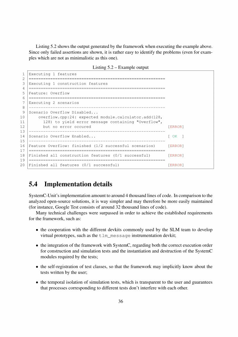
Listing 5.2 shows the output generated by the framework when executing the example above.Since only failed assertions are shown, it is rather easy to identify the problems (even for exam-ples which are not as minimalistic as this one).
Listing 5.2 – Example output1 Executing 1 features2 =========================================================3 Executing 1 construction features4 =========================================================5 Feature: Overflow6 =========================================================7 Executing 2 scenarios8 ---------------------------------------------------------9 Scenario Overflow Disabled...
10 overflow.cpp:24: expected module.calculator.add(128,11 128) to yield error message containing "Overflow",12 but no error occured [ERROR]13 ---------------------------------------------------------14 Scenario Overflow Enabled... [ OK ]15 ---------------------------------------------------------16 Feature Overflow: finished (1/2 successful scenarios) [ERROR]17 =========================================================18 Finished all construction features (0/1 successful) [ERROR]19 =========================================================20 Finished all features (0/1 successful) [ERROR]
5.4 Implementation detailsSystemC-Unit’s implementation amount to around 4 thousand lines of code. In comparison to theanalyzed open-source solutions, it is way simpler and may therefore be more easily maintained(for instance, Google Test consists of around 32 thousand lines of code).
Many technical challenges were surpassed in order to achieve the established requirementsfor the framework, such as:
• the cooperation with the different devkits commonly used by the SLM team to developvirtual prototypes, such as the tlm_message instrumentation devkit;
• the integration of the framework with SystemC, regarding both the correct execution orderfor construction and simulation tests and the instantiation and destruction of the SystemCmodules required by the tests;
• the self-registration of test classes, so that the framework may implicitly know about thetests written by the user;
• the temporal isolation of simulation tests, which is transparent to the user and guaranteesthat processes corresponding to different tests don’t interfere with each other.
36
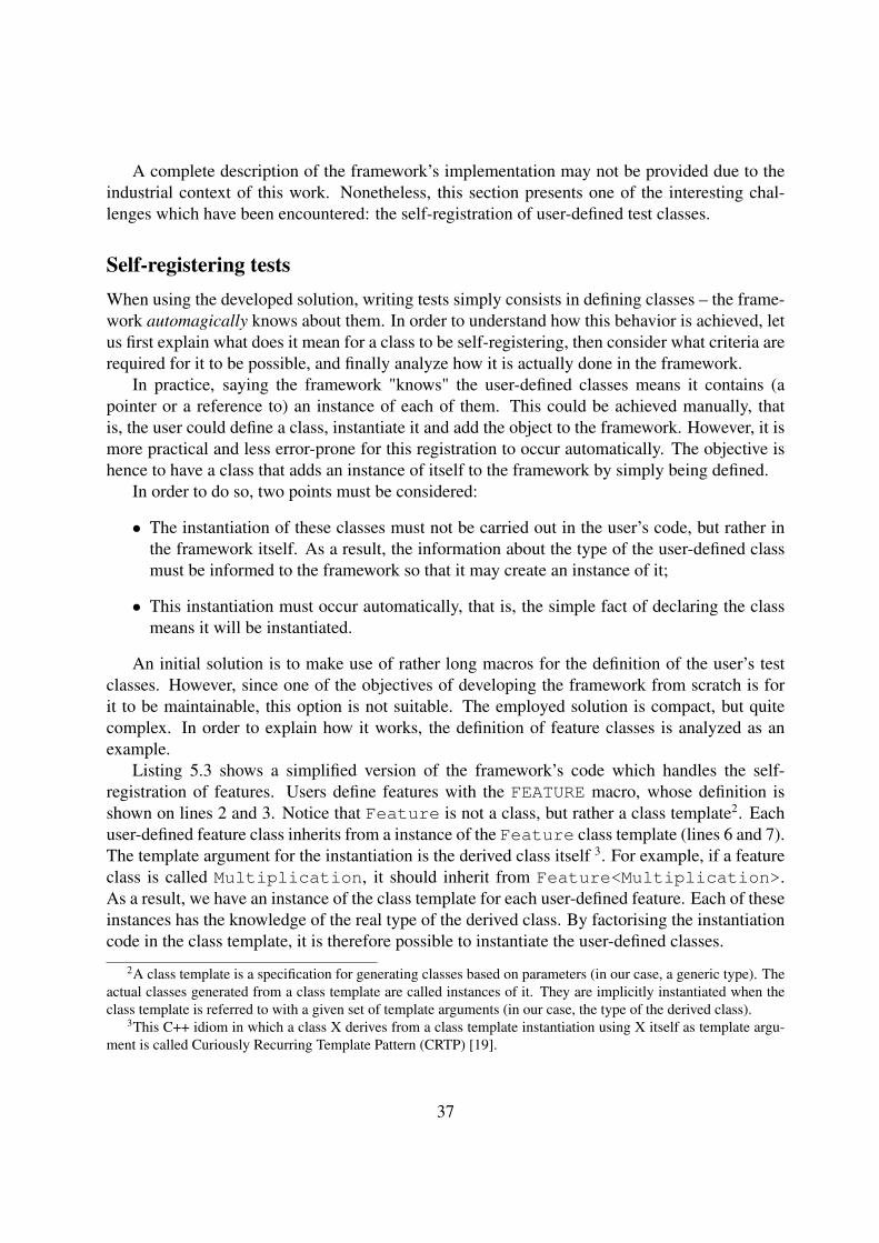
A complete description of the framework’s implementation may not be provided due to theindustrial context of this work. Nonetheless, this section presents one of the interesting chal-lenges which have been encountered: the self-registration of user-defined test classes.
Self-registering testsWhen using the developed solution, writing tests simply consists in defining classes – the frame-work automagically knows about them. In order to understand how this behavior is achieved, letus first explain what does it mean for a class to be self-registering, then consider what criteria arerequired for it to be possible, and finally analyze how it is actually done in the framework.
In practice, saying the framework "knows" the user-defined classes means it contains (apointer or a reference to) an instance of each of them. This could be achieved manually, thatis, the user could define a class, instantiate it and add the object to the framework. However, it ismore practical and less error-prone for this registration to occur automatically. The objective ishence to have a class that adds an instance of itself to the framework by simply being defined.
In order to do so, two points must be considered:
• The instantiation of these classes must not be carried out in the user’s code, but rather inthe framework itself. As a result, the information about the type of the user-defined classmust be informed to the framework so that it may create an instance of it;
• This instantiation must occur automatically, that is, the simple fact of declaring the classmeans it will be instantiated.
An initial solution is to make use of rather long macros for the definition of the user’s testclasses. However, since one of the objectives of developing the framework from scratch is forit to be maintainable, this option is not suitable. The employed solution is compact, but quitecomplex. In order to explain how it works, the definition of feature classes is analyzed as anexample.
Listing 5.3 shows a simplified version of the framework’s code which handles the self-registration of features. Users define features with the FEATURE macro, whose definition isshown on lines 2 and 3. Notice that Feature is not a class, but rather a class template2. Eachuser-defined feature class inherits from a instance of the Feature class template (lines 6 and 7).The template argument for the instantiation is the derived class itself 3. For example, if a featureclass is called Multiplication, it should inherit from Feature<Multiplication>.As a result, we have an instance of the class template for each user-defined feature. Each of theseinstances has the knowledge of the real type of the derived class. By factorising the instantiationcode in the class template, it is therefore possible to instantiate the user-defined classes.
2A class template is a specification for generating classes based on parameters (in our case, a generic type). Theactual classes generated from a class template are called instances of it. They are implicitly instantiated when theclass template is referred to with a given set of template arguments (in our case, the type of the derived class).
3This C++ idiom in which a class X derives from a class template instantiation using X itself as template argu-ment is called Curiously Recurring Template Pattern (CRTP) [19].
37
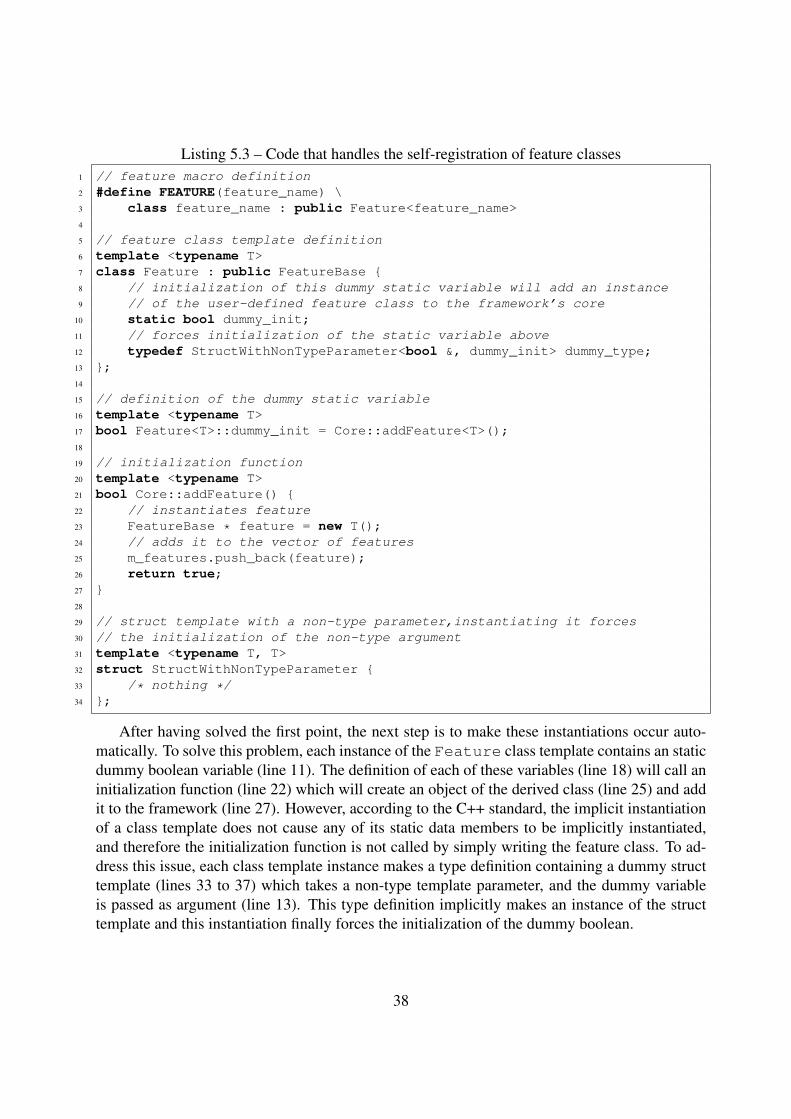
Listing 5.3 – Code that handles the self-registration of feature classes1 // feature macro definition2 #define FEATURE(feature_name) \3 class feature_name : public Feature<feature_name>4
5 // feature class template definition6 template <typename T>7 class Feature : public FeatureBase {8 // initialization of this dummy static variable will add an instance9 // of the user-defined feature class to the framework’s core
10 static bool dummy_init;11 // forces initialization of the static variable above12 typedef StructWithNonTypeParameter<bool &, dummy_init> dummy_type;13 };14
15 // definition of the dummy static variable16 template <typename T>17 bool Feature<T>::dummy_init = Core::addFeature<T>();18
19 // initialization function20 template <typename T>21 bool Core::addFeature() {22 // instantiates feature23 FeatureBase * feature = new T();24 // adds it to the vector of features25 m_features.push_back(feature);26 return true;27 }28
29 // struct template with a non-type parameter,instantiating it forces30 // the initialization of the non-type argument31 template <typename T, T>32 struct StructWithNonTypeParameter {33 /* nothing */34 };
After having solved the first point, the next step is to make these instantiations occur auto-matically. To solve this problem, each instance of the Feature class template contains an staticdummy boolean variable (line 11). The definition of each of these variables (line 18) will call aninitialization function (line 22) which will create an object of the derived class (line 25) and addit to the framework (line 27). However, according to the C++ standard, the implicit instantiationof a class template does not cause any of its static data members to be implicitly instantiated,and therefore the initialization function is not called by simply writing the feature class. To ad-dress this issue, each class template instance makes a type definition containing a dummy structtemplate (lines 33 to 37) which takes a non-type template parameter, and the dummy variableis passed as argument (line 13). This type definition implicitly makes an instance of the structtemplate and this instantiation finally forces the initialization of the dummy boolean.
38
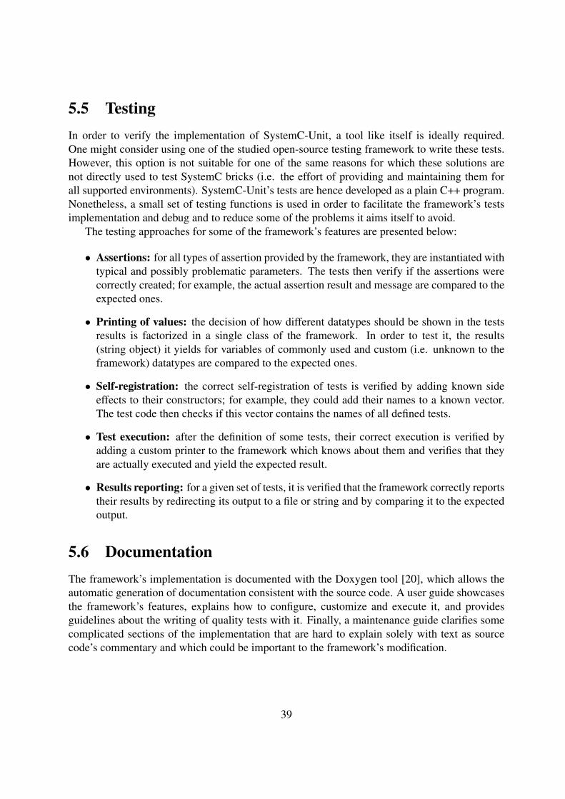
5.5 TestingIn order to verify the implementation of SystemC-Unit, a tool like itself is ideally required.One might consider using one of the studied open-source testing framework to write these tests.However, this option is not suitable for one of the same reasons for which these solutions arenot directly used to test SystemC bricks (i.e. the effort of providing and maintaining them forall supported environments). SystemC-Unit’s tests are hence developed as a plain C++ program.Nonetheless, a small set of testing functions is used in order to facilitate the framework’s testsimplementation and debug and to reduce some of the problems it aims itself to avoid.
The testing approaches for some of the framework’s features are presented below:
• Assertions: for all types of assertion provided by the framework, they are instantiated withtypical and possibly problematic parameters. The tests then verify if the assertions werecorrectly created; for example, the actual assertion result and message are compared to theexpected ones.
• Printing of values: the decision of how different datatypes should be shown in the testsresults is factorized in a single class of the framework. In order to test it, the results(string object) it yields for variables of commonly used and custom (i.e. unknown to theframework) datatypes are compared to the expected ones.
• Self-registration: the correct self-registration of tests is verified by adding known sideeffects to their constructors; for example, they could add their names to a known vector.The test code then checks if this vector contains the names of all defined tests.
• Test execution: after the definition of some tests, their correct execution is verified byadding a custom printer to the framework which knows about them and verifies that theyare actually executed and yield the expected result.
• Results reporting: for a given set of tests, it is verified that the framework correctly reportstheir results by redirecting its output to a file or string and by comparing it to the expectedoutput.
5.6 DocumentationThe framework’s implementation is documented with the Doxygen tool [20], which allows theautomatic generation of documentation consistent with the source code. A user guide showcasesthe framework’s features, explains how to configure, customize and execute it, and providesguidelines about the writing of quality tests with it. Finally, a maintenance guide clarifies somecomplicated sections of the implementation that are hard to explain solely with text as sourcecode’s commentary and which could be important to the framework’s modification.
39
5.7 ValidationIn order to evaluate if the developed framework meets its users’ requirements, the followingvalidation activities were carried out:
• Throughout the implementation, some of the existing tests for the initially analyzed baseelement (the register bank) have been rewritten with the framework. Its correct operationhas therefore been verified by checking that the new tests yield the same results as theprevious ones.
• During the framework’s development, when the feature list was somewhat mature, a meet-ing was held with its future users. The objective was to show an intermediate version ofthe solution in order to obtain feedback about whether it met their needs. Moreover, theintended features yet to be developed were also presented, so that developers could val-idate that the development was going in the right direction. The reactions were mostlypositive, as there were not many reproaches and most comments concerned the addition ofnon-critical features.
• Some existing tests for the SystemC bricks other than the initially analyzed ones wererewritten. This not only validates the framework’s operation as above but also verifiesthat all the required common features were successfully extracted from the analysis of theregister bank’s tests.
• A developer used the framework to implement a few tests for different SystemC bricks.With his remarks, it was possible to validate the framework’s impact in performance: theaverage size reduction in lines of code for the rewritten tests was 21%. Moreover, a fewunclear interfaces and documentation were identified and fixed.
40
6. Concluding Remarks
The objective of this work was to solve the problem of testing reusable SystemC elements, whichare used to construct virtual prototypes of hardware systems. Initially, an analysis of the SLMteam’s development environment and of the existing tests of an example base element yielded aset of constraints to be respected for the testing of these elements. Next, the analysis of someopen-source testing frameworks allowed not only the verification of their applicability regardingthe already defined requirements, but also the identification of new ones.
Since it was concluded that the studied frameworks are not suitable for the testing of SystemCelements, a solution had to be developed from scratch. The proposed unit testing framework forSystemC elements was called SystemC-Unit. A set of features to satisfy the established require-ments was defined and fully implemented. Its implementation amounts to around 4 thousandlines of code, way less than the studied open-source frameworks. Furthermore, SystemC-Unitwas fully documented, tested and validated. Tests written with SystemC-Unit are, in average,21% smaller (in lines of code) than the previously existing tests.
A first official version of the test framework has been released for the System Level Modelingteam. Its maintenance will be responsibility of this project’s supervisor; this is a logical choicesince he followed and guided the project’s development from the beginning.
In time to come, the framework may be extended in order to support the testing of morecomplex SystemC components (e.g. a complete model of an IP block), which are built uponthe reusable bricks that the developed tool aims to test. Even though the requirements for thesemodels are different than those for the aforementioned bricks, many aspects of the frameworkmay surely be leveraged.
41
Bibliography
[1] Accellera Systems Initiative. The SystemC standard. http://www.accellera.org/downloads/standards/systemc. Accessed: 25 March, 2016.
[2] STMicroelectronics. ST company information. http://www.st.com/web/en/about_st/st_company_information.html. Accessed: 25 March, 2016.
[3] Accellera Systems Initiative. The IP-XACT standard. http://www.accellera.org/downloads/standards/ip-xact. Accessed: 25 March, 2016.
[4] Michael Nash. Overcoming not invented here syndrome. http://www.developer.com/design/article.php/3338791/Overcoming-quotNot-Invented-Herequot-Syndrome.htm. Accessed: 25 March, 2016.
[5] Accellera Systems Initiative. Accellera Systems Initiative presentation. http://www.accellera.org/about. Accessed: 25 March, 2016.
[6] Ian Sommerville. Engenharia de software. Pearson Brasil, 2011.
[7] Gerard Meszaros. xUnit Test Patterns: Refactoring Test Code. Addison-Wesley SignatureSeries (Fowler). Pearson Education, 2007.
[8] Michaela Greiler, Andy Zaidman, Arie van Deursen, and Margaret-Anne Storey. Strate-gies for avoiding text fixture smells during software evolution. In Proceedings of the 10thWorking Conference on Mining Software Repositories, pages 387–396. IEEE Press, 2013.
[9] Cucumber Limited. Gherkin. https://github.com/cucumber/cucumber/wiki/Gherkin. Accessed: 1 December, 2016.
[10] J.F. Smart. BDD in Action: Behavior-Driven Development for the Whole Software Lifecy-cle. Manning Publications Company, 2014.
[11] Cucumber Limited. The Cucumber framework. https://cucumber.io/. Accessed:25 March, 2016.
[12] Ruby community. The Ruby programming language. https://www.ruby-lang.org/en/about/. Accessed: 7 June, 2016.
42
[13] Cucumber Limited. The Cucumber C++ implementation. https://github.com/cucumber/cucumber-cpp. Accessed: 25 March, 2016.
[14] Cucumber Limited. The Cucumber Wire protocol. https://github.com/cucumber/cucumber/wiki/Wire-Protocol. Accessed: 25 March, 2016.
[15] Boost.Test contributors. The Boost.Test library. http://www.boost.org/doc/libs/release/libs/test/. Accessed: 25 March, 2016.
[16] Google Inc. The Google Test framework. https://github.com/google/googletest. Accessed: 25 March, 2016.
[17] LLVM contributors. LLVM unit tests. http://llvm.org/svn/llvm-project/llvm/trunk/unittests/. Accessed: 4 November, 2016.
[18] OpenCV contributors. OpenCV: C++ tests. http://code.opencv.org/projects/opencv/wiki/QA_in_OpenCV#C-tests. Accessed: 4 November, 2016.
[19] Wikimedia Foundation Inc. More C++ idioms: Curiously Recurring Tem-plate Pattern. https://en.wikibooks.org/wiki/More_C++_Idioms/Curiously_Recurring_Template_Pattern. Accessed: 25 May, 2016.
[20] Dimitri van Heesch. Doxygen. http://www.doxygen.org/. Accessed: 1 December,2016.
43


![[GUTS-RS] Mobile Testing](https://static.fdocumentos.com/doc/165x107/58ab60ab1a28abbc2a8b585f/guts-rs-mobile-testing.jpg)