
UNIVERSIDADE DO ALGARVE - CORE · Nas telecomunicações a fibra óptica é uma escolha ......
133
UNIVERSIDADE DO ALGARVE Faculdade de Ciências e Tecnologia Signaling strategies for consumer oriented Grid over Optical Burst Switching networks Mark Emanuel Cavaco Guerreiro Master in Electrical Engineer and Telecommunications 2009
Transcript of UNIVERSIDADE DO ALGARVE - CORE · Nas telecomunicações a fibra óptica é uma escolha ......
UNIVERSIDADE DO ALGARVE Faculdade de Ciências e Tecnologia
Signaling strategies for consumer oriented Grid
over Optical Burst Switching networks
Mark Emanuel Cavaco Guerreiro
Master in Electrical Engineer and Telecommunications
2009


UNIVERSIDADE DO ALGARVE Faculdade de Ciências e Tecnologia
Signaling strategies for consumer oriented Grid
over Optical Burst Switching networks
Mark Emanuel Cavaco Guerreiro
Dissertation supervised by:
Professora Doutora Maria do Carmo Raposo de Medeiros
Master in Electrical Engineer and Telecommunications
2009


i
Declaration
Mark Guerreiro, student of Master in Electrical Engineering and Telecommunications
of Universidade do Algarve declares this document author.
Student:
(Mark Emanuel Cavaco Guerreiro) Supervisor:
(Doutora Maria do Carmo Raposo Medeiros)
Supervisory Committee:
(Doutor António Eduardo Barros Ruano)
(Doutor Joel José Puga Coelho Rodrigues)
(Doutora Maria do Carmo Raposo de Medeiros)

iii
Abstract
The concept of Grid networks has recently emerged as an infrastructure able to
support, both scientific and commercial applications. The Grid is a dynamic, distributed
collection of heterogeneous computational, storage and network resources geographically
distributed and shared between organizations.
Optical Burst Switching (OBS) networks have been identified as a technology with
potential to support the requirements of the Grids. This approach, known as Grid over Optical
Burst Switching (GOBS) is currently the object of intensive research.
This dissertation focus is on GOBS architectures employing Active OBS Routers with
centralized control. This approach enables the balance of the overall network traffic
potentially minimizing congestion and consequently reducing job blocking. Two different
strategies are explored.
The first strategy is a novel signaling scheme applied to a GOBS network employing
Active Routers. The Active Router reduces the job blocking probability, because the path
used by the Data Burst to reach the Grid Job Resource is selected based on the network actual
status. Since the Active Router maintains the network status always updated, the bursts are
only dropped when is not possible to connect the source to the end node. Another study
associated with this signaling scheme is the reservation time. It is demonstrated that this
approach decreases the network blocking probability at the same time that decreases the time
delay that a job suffers until it reaches the Grid service provider.
In the second strategy, the Active Router only select the Grid Resource used to resolve
the job, the path used to reach it is selected by the Grid client based on the probabilistic model
for the link demands. The probabilistic model is used to predict a possible network usage
based on the demands from all nodes to all nodes. The results obtained show overall
performance improvement.
Key words: Grid, OBS, Grid over OBS, consumer oriented Grids, signaling scheme, path
selection strategies and OMNeT++.

v
Resumo
Nas telecomunicações a fibra óptica é uma escolha interessante, porque permite taxas
de transmissão com uma ordem de grandeza de 1000 vezes superiores às suportadas pelo
cobre, onde cada fibra suporta vários terabits por segundo (Tbps). A tecnologia Wavelength
Division Multiplexing (WDM) permite separar a largura de banda disponível numa fibra
óptica em vários canais que permitem a transmissão independente de dados. Optical Burst
Switching (OBS) é um paradigma introduzido por [1] para as redes ópticas. Os seus autores
propõem um esquema onde vários pacotes com o mesmo nó de destino e iguais requisitos são
agrupados num super pacote denominado burst. Nas redes OBS, os recursos de rede são
reservados previamente para a transmissão do burst. Para reservar os recursos de rede, antes
de enviar o burst, um pacote de controlo é transmitido ao longo do mesmo itinerário. Desta
forma quando um nó recebe o burst encaminha-o imediatamente para a porta e comprimento
de onda correctos de saída. Nas redes OBS podem ser utilizados vários esquemas de
sinalização para reservar os recursos de rede, tais como por exemplo os Just Enough Time
(JET), Just In Time (JIT) e o Wavelenght Routed (WR-OBS).
Uma Grid é um conjunto de recursos computacionais (armazenamento ou
processamento) espalhados ao longo da rede. Nas Grids, os clientes enviam para a rede os
processos para serem resolvidos. Numa Grid, os nós centrais não precisam de ter informação
sobre a disposição dos vários servidores responsáveis por resolver trabalhos específicos, basta
possuírem informação suficiente para encaminharem o processo para um servidor com
capacidade para a sua resolução. No início, as Grids eram utilizadas por aplicações
académicas, que necessitavam de muitos recursos. Recentemente, as vantagens inerentes as
redes Grid foram estendidas a aplicações comerciais, caracterizadas por uma duração curta.
Nos modelos comerciais as capacidades de encaminhamento rápido são muito importantes,
pois os recursos de rede vão estar ocupados somente durante curtos espaços de tempo para
cada aplicação.
As vantagens propostas pelas Grids podem ser suportadas pelas redes OBS. A
utilização das Grid sobre as redes OBS denomina-se Grid over OBS (GOBS). Nessas redes
são utilizadas funcionalidades específicas das redes OBS para os clientes acederem aos
serviços de Grid. A principal diferença entre uma Grid e uma GOBS é que nas Grids, o cliente
não necessita ter conhecimento de onde está localizado o nó que fornece serviço, enquanto

vi
nas GOBS, antes da transmissão do burst com os jobs é necessário que no inicial conheça a
localização dos servidores de recursos seja identificada.
Os esquemas de sinalização mais utilizados nas redes OBS são o Just In Time (JIT) e o
Just Enough Time (JET). As características de ambos os sistemas são apresentadas em detalhe
no capítulo 5. Nas redes OBS os bursts de dados são transmitidos um atraso t depois do
Control Packet (pacote de controlo) ambos utilizando o mesmo itinerário. A informação
contida no Control Packet é utilizada para reservar os recursos de rede utilizados para a
transmissão do burst de dados. Em ambos os esquemas de sinalização a informação contida
no Control Packet é utilizada para garantir que os nós estão preparados para a transmissão dos
dados quando for necessário. A maior diferença entre o JIT e o JET é como são reservados os
recursos de rede. No JET o canal está reservado somente no momento de passagem do burst,
enquanto no JIT, os recursos estão reservados desde que o Control Packet chega até que os
recursos são libertos por um pacote específico para esse efeito. No caso do JET, os recursos
podem ser libertos de uma forma programada, ou tal como no JIT utilizando um pacote
especifico para libertar os recursos anteriormente reservados.
Outro esquema de sinalização utilizado nas redes OBS é o Wavelength Routed – OBS
(WR-OBS), onde um nó central é responsável pela reserva dos recursos de rede.
Nesta dissertação de mestrado propomos um esquema de sinalização para redes Grid
over OBS baseado em Active Routers. O sistema proposto é semelhante ao utilizado em [2] e
[3]. As principais diferenças entre o esquema proposto por [2] e [3] e o considerado neste
trabalho é que para além da localização dos servidores de Grid, o nó central (Active Router)
tem um papel preponderante na reserva dos recursos de rede. O Active Router tem um
conhecimento global arquitectura da rede e de todas as ligações existentes. Como o Active
Router é responsável por seleccionar o melhor local para resolver o Job escolhe a melhor rota
para ligar o cliente e nó responsável por resolver o Job. Podendo ser atribuídas diferentes
rotas para atingir o Grid Resource baseados nos requisitos de cada Job contidos no Control
Packet. O Active Router após seleccionar a rota começa o processo de reserva de recursos de
rede. A reserva iniciada pelo Active Router permite antecipar a transmissão do burst. Como a
escolha das rotas é baseada no conhecimento global da rede, a ocorrência de perda de burst é
reduzida. As vantagens inerentes à rede considerada são redução da taxa de bloqueios e a
diminuição do atraso de transmissão. A escolha dos caminhos utilizados para atingir o nó de
destino é muito importante na redução das perdas de pacotes na rede. As técnicas utilizadas
podem ser ou não adaptativas. As técnicas de escolha de caminhos adaptativas normalmente
utilizam protocolos de routing para manter actualizadas as tabelas de routing. A informação

vii
contida nas tabelas de routing é utilizada para escolher os melhores caminhos. As estratégias
não adaptativas usam informação estática, como por exemplo a topologia da rede ou a
distancia dos ligações para escolher quais os melhores rotas para alcançar o nó de destino.
Nesta dissertação de mestrado é implementada uma técnica para escolher rotas baseadas num
modelo probabilístico introduzido em [4]. Esta técnica para escolher rotas é não adaptativa, é
aplicada quando a rede é iniciada e funciona do seguinte modo. Define-se a métrica peso do
link que corresponde à probabilidade desse link ser utilizado e o custo de uma rota que
corresponde à soma dos pesos dos seus links. Quanto maior for o custo da rota, maior é a
probabilidade dos seus links serem utilizados. A escolha da rota tem por base o seu custo.
A medida de desempenho em redes OBS mais utilizada é a taxa de bloqueios de
bursts. Por isso é importante estudar técnicas que minimizem a ocorrência de perdas de bursts
nestas redes. Nesta dissertação de mestrado fazemos o estudo de duas técnicas distintas
utilizadas para reduzir a taxa de bloqueio em cenários comercias de redes GRID over OBS. O
primeiro esquema proposto (WR-OBS), também reduz o tempo de reserva das redes GOBS.
A redução do tempo de reserva é muito importante para os sistemas comerciais e redes OBS,
pois diminui o tempo total de transmissão, permitindo antecipar a transmissão dos dados.
Palavras chave: Grid, OBS, Grid over OBS, Grids para consumidores, estratégias de
sinalização, estratégias de escolha de rotas e OMNeT++


ix
Acknowledgments
First I would like to acknowledge my supervisor Professora Doutora Carmo Medeiros,
who since my graduation studies gave me the opportunity to do research work and offered me
new opportunities. During this Master her advice was important, giving me information,
strategies and solutions during all the work.
I also like to acknowledge to my friends and CEOT colleagues, for all support,
friendship, fellowship and a lot of good time spent.
Last but not least, my family, for all the support during this master. A special thank
you to whom that I “obligate” to read my report without understanding the technical matters
in order to improve the quality of my English.


xi
Table of contents
DECLARATION ....................................................................................................................................................I
ABSTRACT ........................................................................................................................................................ III
RESUMO .............................................................................................................................................................. V
ACKNOWLEDGMENTS ................................................................................................................................... IX
TABLE OF CONTENTS .................................................................................................................................... XI
LIST OF FIGURES ........................................................................................................................................... XV
LIST OF TABLES ............................................................................................................................................ XIX
ABBREVIATIONS .......................................................................................................................................... XXI
CHAPTER 1. INTRODUCTION .................................................................................................................... 1
1.1. OPTICAL NETWORKS ............................................................................................................................. 1
1.2. GRID OVER OBS NETWORK ................................................................................................................... 3
1.3. DISSERTATION ORGANIZATION ............................................................................................................. 4
CHAPTER 2. OPTICAL BURST SWITCHING NETWORKS ................................................................... 5
2.1. INTRODUCTION ..................................................................................................................................... 5
2.2. OBS FUNDAMENTALS ........................................................................................................................... 5
2.3. OBS NETWORK ARCHITECTURE ............................................................................................................ 7
2.3.1. Edge node architecture .................................................................................................................... 8
2.3.2. Core Node architecture ................................................................................................................... 9
2.4. CONNECTION SETUP MECHANISMS ...................................................................................................... 10
2.4.1. Signaling for OBS .......................................................................................................................... 10
2.4.2. Routing .......................................................................................................................................... 12
2.4.3. Wavelength Allocation ................................................................................................................... 12
2.5. OFFSET TIME ....................................................................................................................................... 13
2.5.1. Fixed offsets ................................................................................................................................... 13
2.5.2. Statistical offsets ............................................................................................................................ 14
2.5.3. WR-OBS offsets ............................................................................................................................. 14
2.6. BURST AGGREGATION ......................................................................................................................... 15
2.7. BURST SCHEDULING ALGORITHMS ...................................................................................................... 15
2.8. OBS SIGNALING SCHEMES .................................................................................................................. 17
2.8.1. Just-Enough-Time signaling scheme ............................................................................................. 17
2.8.2. Just-In-Time reservation scheme ................................................................................................... 20
2.9. OBS APPLICATIONS ............................................................................................................................ 23
2.10. CHAPTER SUMMARY ............................................................................................................................ 24

xii
CHAPTER 3. GRID OVER OBS NETWORK ARCHITECTURES ......................................................... 25
3.1. INTRODUCTION .................................................................................................................................... 25
3.2. GRID .................................................................................................................................................... 25
3.2.1. Grid networks attributes ................................................................................................................ 25
3.2.2. Grid standards ............................................................................................................................... 28
3.3. GRID OVER OBS .................................................................................................................................. 29
3.3.1. Grid OBS network elements ........................................................................................................... 30
3.3.2. OBS for consumer Grid applications ............................................................................................. 35
3.4. CHAPTER SUMMARY ............................................................................................................................ 37
CHAPTER 4. GRID OVER OBS NETWORK ARCHITECTURE USING ACTIVE ROUTERS ......... 39
4.1. INTRODUCTION .................................................................................................................................... 39
4.2. ACTIVE OBS INFRASTRUCTURE FOR GRIDS ......................................................................................... 39
4.3. ACTIVE OBS ROUTERS ....................................................................................................................... 43
4.3.1. Resource discovery mechanisms .................................................................................................... 44
4.4. CHAPTER SUMMARY ............................................................................................................................ 45
CHAPTER 5. PROPOSED SIGNALING RESERVATION SCHEMES FOR GRID OVER OBS ......... 47
5.1. INTRODUCTION .................................................................................................................................... 47
5.2. SIGNALING SCHEME DESCRIPTION ....................................................................................................... 47
5.2.1. Packet description .......................................................................................................................... 48
5.2.2. Resource reservation ..................................................................................................................... 49
5.2.3. Grid job request and Grid assignment ........................................................................................... 50
5.2.4. Signaling flow ................................................................................................................................ 51
5.2.5. Delays Introduced .......................................................................................................................... 55
5.2.6. Proposed scheme advantages ........................................................................................................ 55
5.3. CHAPTER SUMMARY ............................................................................................................................ 56
CHAPTER 6. IMPLEMENTATION AND PERFORMANCE ASSESSMENT OF THE
RESERVATION SIGNALING SCHEME ........................................................................................................ 57
6.1. INTRODUCTION .................................................................................................................................... 57
6.2. OMNET++ SIMULATION MODEL ......................................................................................................... 57
6.3. NETWORK ............................................................................................................................................ 58
6.3.1. OBS Router .................................................................................................................................... 59
6.3.2. Active Router ................................................................................................................................. 61
6.4. SIGNALING SCHEME OVERVIEW ........................................................................................................... 63
6.5. PERFORMANCE EVALUATION ............................................................................................................... 65
6.5.1. Blocking probability ...................................................................................................................... 66
6.5.2. Reservation time ............................................................................................................................ 69
6.6. CHAPTER SUMMARY ............................................................................................................................ 74
CHAPTER 7. PATH SELECTION STRATEGIES ..................................................................................... 77

xiii
7.1. INTRODUCTION ................................................................................................................................... 77
7.2. STATIC CONTENTION AVOIDANCE STRATEGIES ................................................................................... 77
7.3. ADAPTIVE PATH SELECTION STRATEGIES ............................................................................................ 77
7.3.1. Pure path selecting strategies ........................................................................................................ 78
7.3.2. Hybrid path selecting strategies .................................................................................................... 79
7.4. PATH SELECTION STRATEGY BASED ON A PROBABILISTIC MODEL FOR THE LINK DEMANDS ................. 79
7.4.1. Probabilistic model mathematical representation ......................................................................... 80
7.5. PROBABILISTIC MODEL PERFORMANCE EVALUATION .......................................................................... 81
7.5.1. Network ......................................................................................................................................... 82
7.5.2. Sorting technique: increasing ........................................................................................................ 83
7.5.3. Sorting technique: decreasing ....................................................................................................... 86
7.5.4. Sorting technique: round robin ..................................................................................................... 88
7.5.5. Sorting technique: alternate from increasing to decreasing ......................................................... 90
7.5.6. Comparison between sorting techniques ....................................................................................... 93
7.6. CHAPTER SUMMARY ............................................................................................................................ 95
CHAPTER 8. CONCLUSIONS AND FUTURE WORK ............................................................................ 96
8.1. CONCLUSION ....................................................................................................................................... 96
8.2. FUTURE WORK .................................................................................................................................... 98
REFERENCES .................................................................................................................................................... 99
PUBLICATIONS ............................................................................................................................................... 105


xv
List of figures FIGURE 1.1 – WDM NETWORK EVOLUTION [5]. ................................................................................................................ 2
FIGURE 2.1 – REPRESENTATION OF THE DATA AND CONTROL SIGNALS TRANSMITTED OVER DIFFERENT CHANNELS [11]. .................... 6
FIGURE 2.2 - AN OBS NETWORK EXAMPLE [5]. ................................................................................................................. 8
FIGURE 2.3- EDGE NODE BASIC MODULES [5]. ................................................................................................................... 8
FIGURE 2.4 - TYPICAL ARCHITECTURE OF OBS CORE SWITCH NODE WITH OPTICAL BURST ALIGNMENT CAPACITY [5]. ........................ 9
FIGURE 2.5- ONE-WAY SIGNALLING RESERVATION SCHEME FLOW. ....................................................................................... 11
FIGURE 2.6- AN ILLUSTRATION OF SCHEDULING ALGORITHMS. ............................................................................................ 16
FIGURE 2.7 - JET SIGNALING SCHEME FLOW. ................................................................................................................... 17
FIGURE 2.8 – AN EXAMPLE OF THE DELAYED RESERVATION AND ITS USEFULNESS WITH OR WITHOUT BUFFER [1]. ......................... 19
FIGURE 2.9 – JIT SIGNALLING SCHEME FLOW ................................................................................................................... 21
FIGURE 2.10 - AN OPERATION EXAMPLE OF THE IMMEDIATE RESERVATION PERFORMED BY JIT [27]. .......................................... 22
FIGURE 3.1- CORE OBS ROUTER ARCHITECTURE THAT COMBINES SLOW SWITCHING (OXCS) AND FAST SWITCHING ELEMENTS [29]. 31
FIGURE 3.2- A GRID OVER OBS NETWORK EXAMPLE. ........................................................................................................ 34
FIGURE 4.1 - ACTIVE OBS NETWORK TOPOLOGY FOR GRID SERVICES. ................................................................................... 40
FIGURE 4.2 - GRID RESOURCE REQUEST AND GRID JOB SUBMISSION PROCESS BASED IN JET IN A GOBS NETWORK EMPLOYING ACTIVE
ROUTERS [2][50]. ............................................................................................................................................ 41
FIGURE 4.3 - A COMPLETE GRID JOB COMPRISES THE JOB-SPECIFICATION BURST (ACTIVE) AND THE ACTUAL JOB BURST (NON-ACTIVE)
[2][50]. ......................................................................................................................................................... 41
FIGURE 4.4- A GENERIC MODEL FOR AN ACTIVE OBS ROUTER [50]. .................................................................................... 44
FIGURE 5.1- GENERIC FRAMING STRUCTURE OF THE CONTROL PACKET. (A) GENERIC CONTROL PACKET, (B) ACTIVE BCP, (C) BCP FOR
OXC CONFIGURATION AND (D) BCP ACK. ............................................................................................................. 49
FIGURE 5.2- EXAMPLE OF A SIMPLE MESH ACTIVE DOMAIN NETWORK. .................................................................................. 50
FIGURE 5.3 - TIME SCALE ILLUSTRATION OF A GRID JOB SUBMISSION USING THE PROPOSED SCHEME. ......................................... 53
FIGURE 5.4- TIME SCALE ILLUSTRATION OF A GRID JOB SUBMISSION USING THE JET-OBS SCHEME. ........................................... 54
FIGURE 6.1- 20 NODE EON CONTROLLED BY AN ACTIVE ROUTER. ....................................................................................... 58
FIGURE 6.2- OBS ROUTER INTERNAL SUBMODULES. ......................................................................................................... 61
FIGURE 6.3- ACTIVE ROUTER INTERNAL STRUCTURE. ......................................................................................................... 62
FIGURE 6.4 –A FLUXOGRAM WITH ALL THE TASKS PERFORMED BY THE SIGNALLING SCHEME. ..................................................... 65
FIGURE 6.5- JOB BLOCKING PROBABILITY VERSUS LOAD FOR GRID JOB DURATIONS OF 40, 20, 10, 2 AND 0.5 MS FOR NETWORK
SCENARIO ACTIVE ROUTER IS THE NODE 17 AND JOB RESOURCE IS THE NODE 18. .......................................................... 67
FIGURE 6.6 -JOB BLOCKING PROBABILITY VERSUS LOAD FOR GRID JOB DURATIONS OF 40, 20, 10, 2 AND 0.5 MS FOR NETWORK
SCENARIO ACTIVE ROUTER IS THE NODE 14 AND JOB RESOURCE IS THE NODE 4. ............................................................ 67
FIGURE 6.7- JOB BLOCKING PROBABILITY USING SIGQUEUE FOR GRID JOB DURATIONS OF 40, 20, 10 AND 5 MS. ......................... 68
FIGURE 7.1- A) A NETWORK TOPOLOGY, REPRESENTED BY A GRAPH; B) THE MATRIX lp FOR LINK 1 (L=1). ............................. 81

xvi
FIGURE 7.2 - COST239 GRID OVER OBS TOPOLOGY, WHERE THE NODE 6 IS THE ACTIVE ROUTER AND THE NODE 5 IS THE GRID JOB
RESOURCE. ...................................................................................................................................................... 82
FIGURE 7.3 - JOB BLOCKING PROBABILITY VERSUS LOAD USING EON NETWORK WITH THE NODE 14 AS ACTIVE ROUTER AND THE NODE
4 IS THE JOB RESOURCE. THE PATHS ARE RANKED BY IS WEIGHT FOR THE JOB DURATIONS OF A) 0.2, 0.5, 1.0 AND 2.0MS, B)
5.0, 10.0, 20.0 AND 40.0 MS AND C) 5.0, 10.0, 20.0 AND 40.0 MS FOR LOWER LOADS. ............................................. 84
FIGURE 7.4 - JOB BLOCKING PROBABILITY VERSUS LOAD USING COST 239 NETWORK WITH THE NODE 6 AS ACTIVE ROUTER AND THE
NODE 5 IS THE JOB RESOURCE. THE PATHS ARE RANKED BY IS WEIGHT FOR THE JOB DURATIONS OF A) 0.2, 0.5, 1.0 AND 2.0MS,
B) 5.0, 10.0, 20.0 AND 40.0 MS AND C) 5.0, 10.0, 20.0 AND 40.0 MS FOR LOWER LOADS. ......................................... 84
FIGURE 7.5 - JOB BLOCKING PROBABILITY VERSUS LOAD USING COST 239 NETWORK WITH THE NODE 6 AS ACTIVE ROUTER AND THE
NODE 7 IS THE JOB RESOURCE. THE PATHS ARE RANKED BY IS WEIGHT FOR THE JOB DURATIONS OF A) 0.2, 0.5, 1.0 AND 2.0MS,
B) 5.0, 10.0, 20.0 AND 40.0 MS AND C) 5.0, 10.0, 20.0 AND 40.0 MS FOR LOWER LOADS. ......................................... 85
FIGURE 7.6 - JOB BLOCKING PROBABILITY VERSUS LOAD USING EON NETWORK WITH THE NODE 14 AS ACTIVE ROUTER AND THE NODE
4 IS THE JOB RESOURCE. THE PATHS ARE RANKED BY THE INVERSE WEIGHT FOR THE JOB DURATIONS OF A) 0.2, 0.5, 1.0 AND
2.0MS, B) 5.0, 10.0, 20.0 AND 40.0 MS AND C) 5.0, 10.0, 20.0 AND 40.0 MS FOR LOWER LOADS. .............................. 86
FIGURE 7.7 - JOB BLOCKING PROBABILITY VERSUS LOAD USING COST 239 NETWORK WITH THE NODE 6 AS ACTIVE ROUTER AND THE
NODE 5 IS THE JOB RESOURCE. THE PATHS ARE RANKED BY THE INVERSE WEIGHT FOR THE JOB DURATIONS OF A) 0.2, 0.5, 1.0
AND 2.0MS, B) 5.0, 10.0, 20.0 AND 40.0 MS AND C) 5.0, 10.0, 20.0 AND 40.0 MS FOR LOWER LOADS. ....................... 87
FIGURE 7.8 - JOB BLOCKING PROBABILITY VERSUS LOAD USING COST 239 NETWORK WITH THE NODE 6 AS ACTIVE ROUTER AND THE
NODE 7 IS THE JOB RESOURCE. THE PATHS ARE RANKED BY THE INVERSE WEIGHT FOR THE JOB DURATIONS OF A) 0.2, 0.5, 1.0,
2.0MS AND B) 5.0, 10.0, 20.0 AND 40.0 MS AND C) 5.0, 10.0, 20.0 AND 40.0 MS FOR LOWER LOADS. ........................ 87
FIGURE 7.9 - JOB BLOCKING PROBABILITY VERSUS LOAD USING EON NETWORK WITH THE NODE 14 AS ACTIVE ROUTER AND THE NODE
4 IS THE JOB RESOURCE. THE PATHS ARE RANKED USING THE ROUND ROBIN FOR THE JOB DURATIONS OF A) 0.2, 0.5, 1.0 AND
2.0MS, B) 5.0, 10.0, 20.0 AND 40.0 MS AND C) 5.0, 10.0, 20.0 AND 40.0 MS FOR LOWER LOADS. .............................. 89
FIGURE 7.10 - JOB BLOCKING PROBABILITY VERSUS LOAD USING COST 239 NETWORK WITH THE NODE 6 AS ACTIVE ROUTER AND THE
NODE 5 IS THE JOB RESOURCE. THE PATHS ARE RANKED USING THE ROUND ROBIN FOR THE JOB DURATIONS OF A) 0.2, 0.5, 1.0,
2.0MS, B) 5.0, 10.0, 20.0 AND 40.0 MS AND C) 5.0, 10.0, 20.0 AND 40.0 MS FOR LOWER LOADS. .............................. 89
FIGURE 7.11 - JOB BLOCKING PROBABILITY VERSUS LOAD USING COST 239 NETWORK WITH THE NODE 6 AS ACTIVE ROUTER AND THE
NODE 7 IS THE JOB RESOURCE. THE PATHS ARE RANKED USING THE ROUND ROBIN FOR THE JOB DURATIONS OF A) 0.2, 0.5, 1.0
AND 2.0MS, B) 5.0, 10.0, 20.0 AND 40.0 MS AND C) 5.0, 10.0, 20.0 AND 40.0 MS FOR LOWER LOADS. ....................... 90
FIGURE 7.12 - JOB BLOCKING PROBABILITY VERSUS LOAD USING EON NETWORK WITH THE NODE 14 AS ACTIVE ROUTER AND THE
NODE 4 IS THE JOB RESOURCE. THE PATHS ARE RANKED ALTERNATING FROM INCREASE TO DECREASE ORDER FOR THE JOB
DURATIONS OF A) 0.2, 0.5, 1.0 AND 2.0MS, B) 5.0, 10.0, 20.0 AND 40.0 MS AND C) 5.0, 10.0, 20.0 AND 40.0 MS FOR
LOWER LOADS. .................................................................................................................................................. 91
FIGURE 7.13 - JOB BLOCKING PROBABILITY VERSUS LOAD USING COST 239 NETWORK WITH THE NODE 6 AS ACTIVE ROUTER AND THE
NODE 5 IS THE JOB RESOURCE. THE PATHS ARE RANKED ALTERNATING FROM INCREASE TO DECREASE ORDER FOR THE JOB
DURATIONS OF A) 0.2, 0.5, 1.0 AND 2.0MS, B) 5.0, 10.0, 20.0 AND 40.0 MS AND C) 5.0, 10.0, 20.0 AND 40.0 MS FOR
LOWER LOADS. .................................................................................................................................................. 92

xvii
FIGURE 7.14 - JOB BLOCKING PROBABILITY VERSUS LOAD USING COST 239 NETWORK WITH THE NODE 6 AS ACTIVE ROUTER AND THE
NODE 7 IS THE JOB RESOURCE. THE PATHS ARE RANKED ALTERNATING FROM INCREASE TO DECREASE ORDER FOR THE JOB
DURATIONS OF A) 0.2, 0.5, 1.0 AND 2.0MS, B) 5.0, 10.0, 20.0 AND 40.0 MS AND C) 5.0, 10.0, 20.0 AND 40.0 MS FOR
LOWER LOADS. ................................................................................................................................................. 92
FIGURE 7.15 - COMPARISON BETWEEN THE 4 STRATEGIES FOR SMALL BURSTS DURATIONS AND LOW LOADS, FOR EON TOPOLOGY
WITH THE ACTIVE ROUTER IN NODE 14 AND THE NODE 4 JOB PROVIDER. ..................................................................... 93
FIGURE 7.16 - COMPARISON BETWEEN THE 4 STRATEGIES FOR SMALL BURSTS DURATIONS AND LOW LOADS, FOR COST239 TOPOLOGY
WITH THE ACTIVE ROUTER IN NODE 6 AND THE NODE 5 JOB PROVIDER. ....................................................................... 94
FIGURE 7.17 - COMPARISON BETWEEN THE 4 STRATEGIES FOR SMALL BURSTS DURATIONS AND LOW LOADS, FOR COST239 TOPOLOGY
WITH THE ACTIVE ROUTER IN NODE 6 AND THE NODE 7 JOB PROVIDER. ....................................................................... 94


xix
List of tables
TABLE 6.1 – DELAYS INTRODUCED BY THE NETWORK DURING THE SIMULATION. ..................................................................... 69
TABLE 6.2 – RESERVATION TIME IN MILLISECONDS IN A BUFFERLESS NETWORK WHERE THE NODE 18 IS THE ACTIVE ROUTER AND THE
NODE 17 IS THE JOB RESOURCE. .......................................................................................................................... 70
TABLE 6.3- RESERVATION TIME IN MILLISECONDS IN A BUFFERLESS NETWORK WHERE THE NODE 14 IS THE ACTIVE ROUTER AND THE
NODE 4 IS THE JOB RESOURCE. ............................................................................................................................ 70
TABLE 6.4- AVERAGE, MAXIMUM AND MINIMUM RESERVATION TIME IN A BUFFERED NETWORK WHERE THE NODE 14 IS THE ACTIVE
ROUTER AND THE NODE 4 IS THE JOB RESOURCE, WITH 5MS OF AVERAGE MESSAGE DURATION AND 10 MS OF AVERAGE TIME
BETWEEN THE GENERATION OF THE JOB REQUESTS. .................................................................................................. 72
TABLE 6.5- AVERAGE, MAXIMUM AND MINIMUM RESERVATION TIME IN A BUFFERED NETWORK WHERE THE NODE 14 IS THE ACTIVE
ROUTER AND THE NODE 4 IS THE JOB RESOURCE, WITH 5MS OF AVERAGE MESSAGE DURATION AND 5MS OF AVERAGE TIME
BETWEEN THE GENERATION OF THE JOB REQUESTS. .................................................................................................. 72
TABLE 6.6- AVERAGE, MAXIMUM AND MINIMUM RESERVATION TIME IN A BUFFERED NETWORK WHERE THE NODE 14 IS THE ACTIVE
ROUTER AND THE NODE 4 IS THE JOB RESOURCE, WITH 1MS OF AVERAGE MESSAGE DURATION AND 5MS OF AVERAGE TIME
BETWEEN THE GENERATION OF THE JOB REQUESTS. .................................................................................................. 73
TABLE 6.7- AVERAGE, MAXIMUM AND MINIMUM RESERVATION TIME IN A BUFFERED NETWORK WHERE THE NODE 14 IS THE ACTIVE
ROUTER AND THE NODE 4 IS THE JOB RESOURCE, WITH 0.1MS OF AVERAGE MESSAGE DURATION AND 5MS OF AVERAGE TIME
BETWEEN THE GENERATION OF THE JOB REQUESTS. .................................................................................................. 74


xxi
Abbreviations
ADM Add-and-Drop Multiplexer
ATM Asynchronous Transfer Mode
AWG Arrayed Waveguide Grating
BBMs Buffered Burst Multiplexers
BCP Burst Control Packet
BER Bit Error Rate
BHP Burst Header Packet
BM Burst Module
CCG Control Channel Group
CIM Common Information Model
CP Control Packet
CPP Control Packet Processor
CWDM Coarse Wavelength Division Multiplexing
DB Data Burst
DCG Data Channel Group
DMTF Distributed Management Task Force
DR Delayed Reservation
DWDM Dense Wavelength Division Multiplexing
DWNV Dynamic Weighted Nonbinary Voting
EEP End-to-End Path Priority-Based
EGA Enterprise Grid Alliance
EON European Optical Network
FCFS First Come First Served
FDL Fiber Delay Line
FDL-BBMs Fiber Delay Line- Based Buffered burst Multiplexers.
FECs Forward Equivalent classes
FIFO First In First Out
GGF Global Grid Forum
GOBS Grid over Optical Burst Switching
G-OUNI Grid User Optical Network Interface

xxii
GridDiffServ Grid Differentiated Services
GRNI Grid Resources Network interface
GUNI Grid User Optical Network Interface
IEEE Institute of Electrical and Electronic Engineers
IP Internet Protocol
ITU International Telecommunications Union
ITU-T International Telecommunications Union - Telecommunications
JET Just-Enough-Time
JIT Just-In-Time
JRR Job Resource Request
LAUC Latest Available Unscheduled Channel
LAUC-VF Latest Available Unscheduled Channel Void Filling
LM Line Modules
LSA Link State Advertisement
MBV Majority Binary Voting
MEMS Micro Electro Mechanical Systems
Min-EV Minimum Ending Void
Min-SV Minimum Starting Void.
MPI Message Passing Interface
MPLS Multi Protocol Layer Switching
NPs Network Processors
OBS Optical Burst Switching
OBSN Optical Burst Switching Networks
OCS Optical Circuit Switching
OGSA Open Grid Services Architectures
OPS Optical Packet Switching
OXC Optical Cross Connect
QoS Quality of Service
RAM Random Access Memory
RWA Routing and Wavelength Allocation
SM Switch Module
SOA Semiconductor Optical Amplifier
SOAP Simple Object Access Protocol

xxiii
TAG Tell and Go
TTL Time To Live
W3C World Wide Web Consortium
WADM Wavelength Add-and-Drop Multiplexer
WDM Wavelength Division Multiplexing
WBLU Weighted Bottleneck Link Utilization
WNV Weighted Nonbinay Voting
WLC Weighted Link Congestion
WR-OBS Wavelength-Routed Optical Burst Switching
WRONs Wavelength-Routed Optical Networks
WSDL Web Services Description Language
WSRF Web Service Resource Framework
WWW World Wide Web
XML Extensible Markup Language

Introduction
1
Chapter 1. Introduction
1.1. Optical networks
We live in an information era, where the massive uses of the World Wide Web
(WWW) cause an everyday increase of the demands for network bandwidth. The Internet
traffic high congestion and long delays makes the current infrastructure unable to support
these every growing demands [1].
The optical networks are the natural choice to cope with this massive bandwidth
growth demand. Optical networks are a perfect choice, because the fiber has several Tbps of
operation, low signal attenuation, low signal distortion, low power requirements and slow
aging. For optical networks be the perfect choice, they need to offer reliability, transparency,
simplicity and scalability [5].
A key technology in developing optical networks is Wavelength Division
Multiplexing (WDM). WDM exploits the wide communication bandwidth in the optical fiber.
It allows separate the available bandwidth in different wavelengths, allowing the transmission
of different signals over the same fiber[6].
WDM systems may be classified as Coarse or Dense WDM, referred to as CWDM or
DWDM respectively. This classification depends on the wavelength spacing and compliance
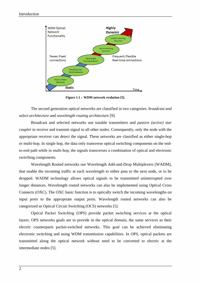
with the International Telecommunications Union (ITU) [7]. Figure 1.1 presents the evolution
of WDM networks over time. The classification is in the following order:
• First Generation Optical Networks;
• Second Generation Optical Networks;
• Optical Packet Switching Networks;
• Optical Burst Switching Networks.
First generation optical architecture only supports point-to-point configurations. At
each node, the entire traffic needs to be converted from optical to electrical, and if the data
need to be retransmitted for the next node, it is necessary another conversion from electrical
to optical. The specific network devices used are Add-and-Drop Multiplexer (ADM). The
ADMs are costly and introduces higher delay and possibly electronic bottleneck [5].
Introduction
2
Figure 1.1 – WDM network evolution [5].
The second generation optical networks are classified in two categories: broadcast and
select architecture and wavelength routing architecture [9].
Broadcast and selected networks use tunable transmitters and passive (active) star
coupler to receive and transmit signal to all other nodes. Consequently, only the node with the
appropriate receiver can detect the signal. These networks are classified as either single-hop
or multi-hop. In single hop, the data only transverse optical switching components on the end-
to-end path while in multi-hop, the signals transverses a combination of optical and electronic
switching components.
Wavelength Routed networks use Wavelength Add-and-Drop Multiplexers (WADM),
that enable the incoming traffic at each wavelength to either pass to the next node, or to be
dropped. WADM technology allows optical signals to be transmitted uninterrupted over
longer distances. Wavelength routed networks can also be implemented using Optical Cross
Connects (OXC). The OXC basic function is to optically switch the incoming wavelengths on
input ports to the appropriate output ports. Wavelength routed networks can also be
categorized as Optical Circuit Switching (OCS) networks [5].
Optical Packet Switching (OPS) provide packet switching services at the optical
layers. OPS networks goals are to provide in the optical domain, the same services as their
electric counterparts packet-switched networks. This goal can be achieved eliminating
electronic switching and using WDM transmission capabilities. In OPS, optical packets are
transmitted along the optical network without need to be converted to electric at the
intermediate nodes [5].
Introduction
3
Optical Burst Switching (OBS) combines the advantages presented in circuit switching
and packet switching. In OBS networks, the incoming data is assembled in super size packets
called Data Bursts (DB), which are transmitted over the optical core network. Signaling is
transmitted out of band. The Control Packet (CP), which carry information such as the length,
the address destination and the Quality of Service (QoS) requirements of the burst and are
used for the path configuration. The Control Packets and the Data Bursts are transmitted along
the same path. The signaling is transmitted using a separate wavelength exclusively reserved
for signaling. The CP is transmitted an offset time before the DB. This offset is used to
guarantee that the Control Packet is processed at each intermediate node before the burst
arrival.
1.2. Grid over OBS network
Grid over OBS (GOBS) networks use the OBS network to enable Grid services. Grids
are dynamic distributed collection of heterogeneous computational, storage and networks
resources geographically distributed and shared between organizations [8].
In GOBS one or more application requests, also named as jobs, are assembled in super
size packets called Data Bursts, which are transported over the optical network until reach the
appropriate Grid Resource. In OBS networks, every node needs to communicate in order to
satisfy a traffic demand, while in GOBS, only the source node is predetermined and the Grid
Resource is discovered using a fast resource discovery mechanism. After the Grid resource
discovery mechanism, in case of resource availability, Grid jobs in the form of Data Bursts
are transmitted to the designated Grid Job Provider, using the OBS networks.
The OBS use for the Grid Jobs transmission presents several advantages, such as:
support of existing DWDM infrastructure, minimize the need of optic to electric convertors in
the intermediate nodes, ability to utilize efficiently the link bandwidth and the Grid resources
and provides a low end-to-end latency. The disadvantage of using the OBS network is that
OBS present low reliability, since it normally uses one-way reservation schemes, where the
burst is transmitted without receiving the confirmation that the entire paths was successfully
reserved. Different DBs contenting for the same resource causes burst drop.
Because the unreliability presented in OBS network, this master dissertation proposes
two different strategies to minimize the Data Burst dropping probability. The first strategy

Introduction
4
presented in Chapter 6, considers a WR-OBS network controlled by an Active Router. The
Active Router selects the paths using the global knowledge of the network status and physical
structure. The second strategy proposed, is presented in Chapter 7 where the paths are
selected by the source node using a probabilistic model for the link demand. The paths are
classified according to their usage probability. Based on this classification, the path selection
strategies are implemented.
1.3. Dissertation organization
Beside this introduction chapter, the remainder of this dissertation is organized as follows.
Chapter 2 presents a general overview of OBS networks. Special attention is given to path
reservation mechanisms.
In Chapter 3 Grid over OBS networks are discussed. This chapter starts with the
introduction of Grid. Then the Grid over OBS network is explained. This chapter describes
the network scenario used in this dissertation.
Chapter 4 is dedicated to Grid over OBS networks employing Active Routers and to the
control plane of such networks.
In Chapter 5, we present the signaling scheme developed in this work.
Chapter 6 contains the proposed scheme implementation details. This chapter is concluded
by the signaling scheme performance evaluation, comparing the job dropping probability and
the reservation time with a JET-OBS similar scheme.
Chapter 7 is dedicated to path selection strategy schemes. A path selection strategy based
on the probabilistic model for the link demands, developed in this work is presented,
implemented and its performance is evaluated.
To conclude this dissertation, the chapter 8 contains the conclusions and future work.
Optical Burst Switching networks
5
Chapter 2. Optical Burst Switching networks
2.1. Introduction
Optical Burst Switching is a technology that combines the best features of Optical
Packet Switching (OPS) and Optical Circuit Switching (OCS) networks. One of the OBS
networks advantages is that the data remains in the optical domain along the entire path. This
feature is enabled by the path reservation before the data transmission.
The OBS networks nodes can be classified into: OBS Edge Routers and OBS Core
Routers. The Edge Router aggregates various types of client data into variable-size bursts [1].
The variable-size bursts are also named Data Bursts (DB). To configure the network resources
a Control Packets (CP) is transmitted along the path. The CP is transmitted an offset time
ahead the DB transmission. The offset time is used to guarantee that the network is already
prepared for the burst when it arrives. The CPs are electrically processed at each node along
the path from the source to the end node. While the DB remains in the optical domain along
the entire path. OBS networks normally use a one way reservation scheme, where the DB is
transmitted without waiting for the positive acknowledgements from the intervenient nodes.
This strategy minimizes the end to end transmission time.
The OBS dynamic resource reservation allows for network scalability and
adaptability, which make OBS more suitable to the busty traffic from the Internet [1].
In the following sections OBS networks are discussed in detail. Particularly, the
connection setup mechanism, several burst operations and OBS application scenarios.
2.2. OBS Fundamentals
OBS was designed to support operation in all-optical transmission for WDM
networks. In general, an Optical Burst Switching Network (OBSN) is composed by Edge and
Core OBS Routers. The Edge Routers consists in an electronic router and a burst assembler,
Optical Burst Switching networks
6
while Core Routers are composed by optical switching matrix, a switch control unit, routing
and signaling processors [10].
The Edge Router is responsible to collect data from upper layer users, such as
Asynchronous Transfer Mode (ATM) switches, Internet Protocol (IP) routers, etc. The data is
collected, sorted and assembled in super size packets called bursts (DB) based on the
destination address and its QoS requirements. For each DB is created a Control Packet, which
is transmitted to the destination address an offset time before the burst for the network
resources configuration. The CP contains information about the burst length, destination
address, offset time, etc. OBS use out-of-band signaling, using different wavelengths for the
data and the signaling, because the Control Packets are significantly smaller than the bursts, a
single control channel is enough to carry the Control Packets associated to multiple data
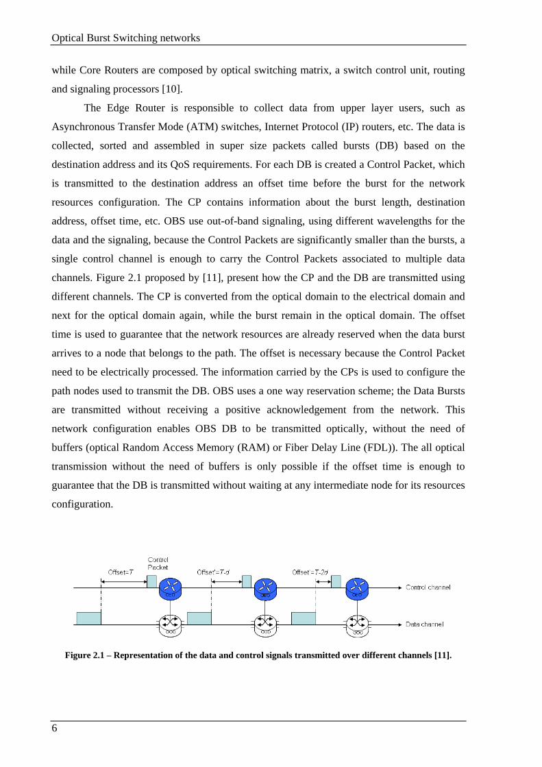
channels. Figure 2.1 proposed by [11], present how the CP and the DB are transmitted using
different channels. The CP is converted from the optical domain to the electrical domain and
next for the optical domain again, while the burst remain in the optical domain. The offset
time is used to guarantee that the network resources are already reserved when the data burst
arrives to a node that belongs to the path. The offset is necessary because the Control Packet
need to be electrically processed. The information carried by the CPs is used to configure the
path nodes used to transmit the DB. OBS uses a one way reservation scheme; the Data Bursts
are transmitted without receiving a positive acknowledgement from the network. This
network configuration enables OBS DB to be transmitted optically, without the need of
buffers (optical Random Access Memory (RAM) or Fiber Delay Line (FDL)). The all optical
transmission without the need of buffers is only possible if the offset time is enough to
guarantee that the DB is transmitted without waiting at any intermediate node for its resources
configuration.
Figure 2.1 – Representation of the data and control signals transmitted over different channels [11].
Optical Burst Switching networks
7
Alternatively the OBS signaling protocol may choose not use any offset. In this case it
is required that at each intermediate node the burst suffers a constant delay. These protocols
are referred as Tell and Go (TAG)-based, since their basic concepts are the same that TAG
[12] [13] itself.
In OBS, the reserved wavelength channel is normally released as soon as the burst
passes through the reserved link. This release can be automatic, using Just Enough Time
(JET) reservation scheme or by an explicit release packet. These techniques enable an
efficient share of the wavelength bandwidth between different nodes to different destinations.
The one-way OBS reservation scheme main advantage is the minimization of the
propagation delay used by the two-way reservation schemes. For this reason the one-way
reservation scheme is used by most OBS networks in order to enable high data rate
transmission. On the other hand, one-way reservation schemes present high burst loss rate.
Since the Control Packet does not reserve the entire path, if it encounters a busy link the
bandwidth already reserved at the previous nodes is wasted. The very fast OBS transmission
rates make impossible to retransmit the dropped Data Bursts or Control Packets. In OBS
networks the retransmission functionality is left to the upper network layers [1] [11].
2.3. OBS network architecture
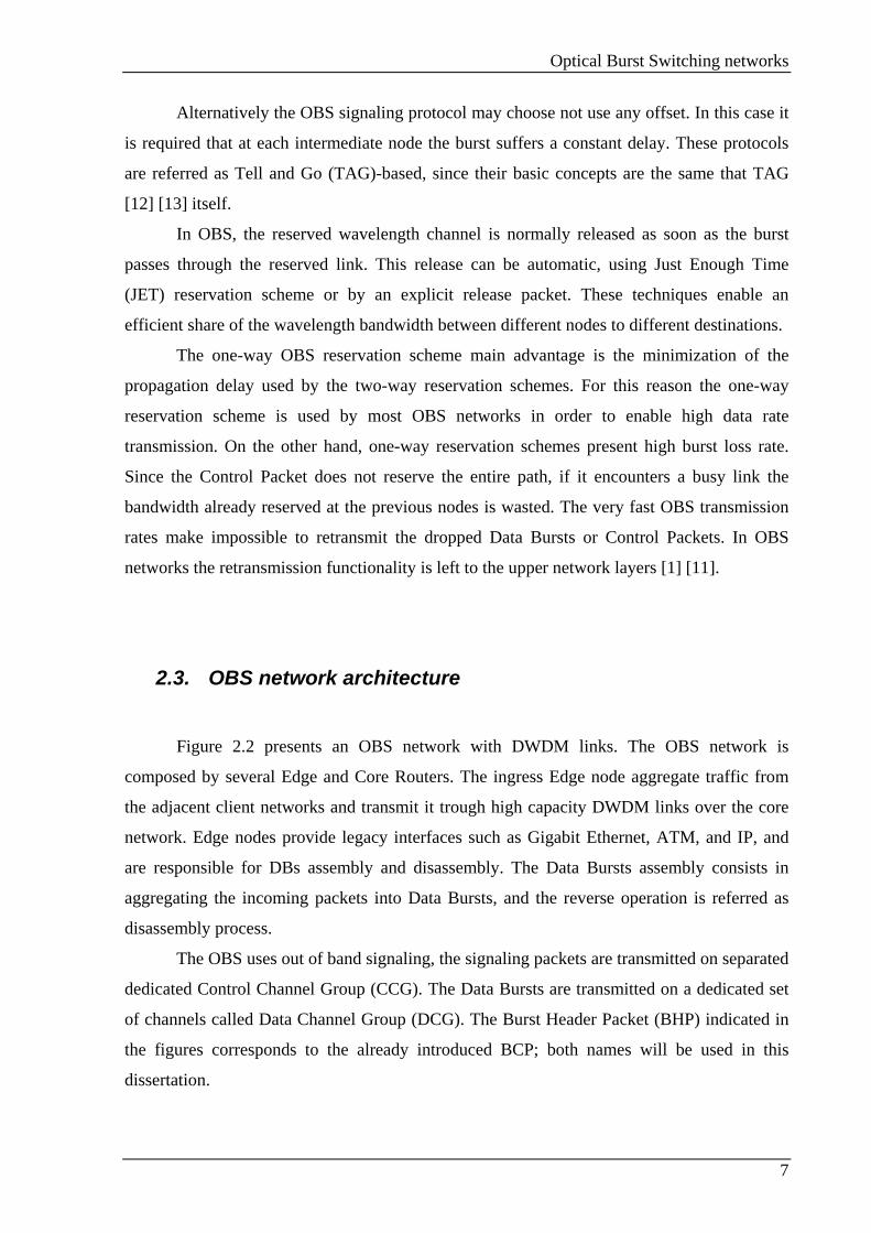
Figure 2.2 presents an OBS network with DWDM links. The OBS network is
composed by several Edge and Core Routers. The ingress Edge node aggregate traffic from
the adjacent client networks and transmit it trough high capacity DWDM links over the core
network. Edge nodes provide legacy interfaces such as Gigabit Ethernet, ATM, and IP, and
are responsible for DBs assembly and disassembly. The Data Bursts assembly consists in
aggregating the incoming packets into Data Bursts, and the reverse operation is referred as
disassembly process.
The OBS uses out of band signaling, the signaling packets are transmitted on separated
dedicated Control Channel Group (CCG). The Data Bursts are transmitted on a dedicated set
of channels called Data Channel Group (DCG). The Burst Header Packet (BHP) indicated in
the figures corresponds to the already introduced BCP; both names will be used in this
dissertation.
Optical Burst Switching networks
8
Figure 2.2 - An OBS network example [5].
2.3.1. Edge node architecture
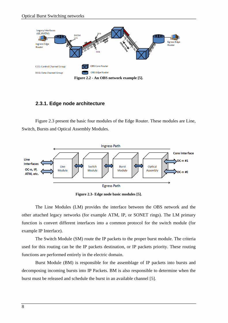
Figure 2.3 present the basic four modules of the Edge Router. These modules are Line,
Switch, Bursts and Optical Assembly Modules.
Figure 2.3- Edge node basic modules [5].
The Line Modules (LM) provides the interface between the OBS network and the
other attached legacy networks (for example ATM, IP, or SONET rings). The LM primary
function is convert different interfaces into a common protocol for the switch module (for
example IP Interface).
The Switch Module (SM) route the IP packets to the proper burst module. The criteria
used for this routing can be the IP packets destination, or IP packets priority. These routing
functions are performed entirely in the electric domain.
Burst Module (BM) is responsible for the assemblage of IP packets into bursts and
decomposing incoming bursts into IP Packets. BM is also responsible to determine when the
burst must be released and schedule the burst in an available channel [5].
Optical Burst Switching networks
9
2.3.2. Core Node architecture
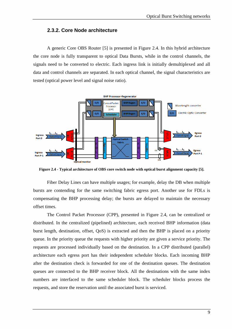
A generic Core OBS Router [5] is presented in Figure 2.4. In this hybrid architecture
the core node is fully transparent to optical Data Bursts, while in the control channels, the
signals need to be converted to electric. Each ingress link is initially demultiplexed and all
data and control channels are separated. In each optical channel, the signal characteristics are
tested (optical power level and signal noise ratio).
Figure 2.4 - Typical architecture of OBS core switch node with optical burst alignment capacity [5].
Fiber Delay Lines can have multiple usages; for example, delay the DB when multiple
bursts are contending for the same switching fabric egress port. Another use for FDLs is
compensating the BHP processing delay; the bursts are delayed to maintain the necessary
offset times.
The Control Packet Processor (CPP), presented in Figure 2.4, can be centralized or
distributed. In the centralized (pipelined) architecture, each received BHP information (data
burst length, destination, offset, QoS) is extracted and then the BHP is placed on a priority
queue. In the priority queue the requests with higher priority are given a service priority. The
requests are processed individually based on the destination. In a CPP distributed (parallel)
architecture each egress port has their independent scheduler blocks. Each incoming BHP
after the destination check is forwarded for one of the destination queues. The destination
queues are connected to the BHP receiver block. All the destinations with the same index
numbers are interfaced to the same scheduler block. The scheduler blocks process the
requests, and store the reservation until the associated burst is serviced.
Optical Burst Switching networks
10
2.4. Connection setup mechanisms
In OBS the connection setup up is separated in three steps. The first is the Burst
Control Packet creation and transmission an offset time ahead of its corresponding Data
Burst; the other two steps are the R (Routing) and the WA (Wavelength Allocation) for each
burst.
2.4.1. Signaling for OBS
The signaling schemes can be classified into distributed with one-way reservation or
centralized with end-to-end reservation.
Distributed signaling with one-way reservation
The one-way signaling reservation is the strategy that is most commonly used in OBS
networks.
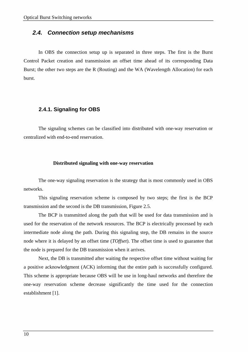
This signaling reservation scheme is composed by two steps; the first is the BCP
transmission and the second is the DB transmission, Figure 2.5.
The BCP is transmitted along the path that will be used for data transmission and is
used for the reservation of the network resources. The BCP is electrically processed by each
intermediate node along the path. During this signaling step, the DB remains in the source
node where it is delayed by an offset time (TOffset). The offset time is used to guarantee that
the node is prepared for the DB transmission when it arrives.
Next, the DB is transmitted after waiting the respective offset time without waiting for
a positive acknowledgment (ACK) informing that the entire path is successfully configured.
This scheme is appropriate because OBS will be use in long-haul networks and therefore the
one-way reservation scheme decrease significantly the time used for the connection
establishment [1].

Optical Burst Switching networks
11
Figure 2.5- One-way signaling reservation scheme flow.
The connection setup time in the one-way reservation scheme is the sum of the
reservation delay with the processing and reconfiguration times from all the nodes used to
connect the source to the end node. In the two-way reservations scheme (eg. circuit
switching), the connection setup time is the sum of the two-way propagation delay, the
reconfiguration and setup time of all nodes [1].
Centralized signaling with End-to-End Reservation
The authors of [15][16][17][18][19] propose a centralized connection scheme, named
Wavelength-Routed Optical Burst Switching (WR-OBS), which uses an end-to-end
reservation scheme. In WR-OBS there is a centralized request server responsible for the entire
OBS network resource scheduling that has total knowledge about the state of the OBS nodes
and the wavelength availability of all the network fiber links. The edge node transmits a CP to
the centralized server. The server queues and processes the CP, using the network global

Optical Burst Switching networks
12
knowledge to select the best path to connect the source node to the end node. After the path
selection, the network status is updated.
In the centralized control with end-to-end reservation the Edge Router only transmits
the DB if receive a positive ACK from the centralized scheduler [1].
2.4.2. Routing
Very high OBS transmission rates require very fast route calculation. Therefore, Edge
Routers must have the ability to pre-determine and pre-calculate routes.
In OBS architectures, the routing algorithms must respect two requirements:
The first requirement is the very fast route calculation. Conventional hop-by-hop IP
routing is not suitable for OBSN; otherwise Multi Protocol Layer Switching (MPLS) is more
advantageous. The authors of [20][21][22] discuss the MPLS implementation in an OBSN.
The idea is at the Edge node assigns the CPs to Forward Equivalent Classes (FECs) to reduce
the intermediate routing time to the time used to swap labels.
The second requirement is the ability to the Edge node pre-determines and pre-
calculates the routes. The MPLS addiction is beneficial, because it makes possible to
explicitly assign the switching labels and route the traffic over the pre-engineered routes.
Explicit routing feature is also very useful in constrain based routing OBS networks, where
the traffic routes have to meet certain QoS requirements, such as delay, hop count, Bit Error
Rate (BER) or bandwidth. In OBS architectures the pre-calculation is required, some OBS
schemes use end-to-end count to estimate the pre-transmission offset times (TOffset of Figure
2.5).
2.4.3. Wavelength Allocation
The wavelength allocation can be realized using two strategies, with or without
wavelength conversion. Using wavelength conversion, the DB is transmitted using a single
wavelength between the source and the end nodes. This strategy results in a high burst loss
because the selected wavelength needs to be free along the entire path. The second strategy
Optical Burst Switching networks
13
uses wavelength conversion capability at each node. In this scenario, when two burst are
contending the same output wavelength, the OBS node may convert optically the wavelength
of one of the bursts to a different output wavelength. Several published work assumes
wavelength conversions capability at each node for better wavelength utilization over the
schemes where no wavelength conversion is used. All-optical wavelength converters are quite
expensive devices and remain a topic of study.
WR-OBS presented by [22] use a First-Fit wavelength-continuity without wavelength
conversion, where the wavelengths are used as routing labels. This idea was first used in
Wavelength-Routed Optical Networks (WRONs). WR-OBS networks use centralized control.
In the WR-OBS networks the controller node has the entire network status knowledge, and
uses this knowledge to search for wavelength available over the selected route. With all the
nodes configured, it is expected that when a burst arrives using a specific port and wavelength
is switched to the appropriate output port using the same wavelength [1].
2.5. Offset time
The offset time guarantees that when the DB arrives, the node is already prepared to
process it. The Edge node sends the BCP an offset time before the DB. Ideally the offset
estimation should be based on the number of hops from the source to the end nodes and the
network congestion. The offset time estimation is very important, because the incorrect
estimation can increase the burst loss. This happens because the DB may arrive to the OBS
Core Router before it is already prepared for it.
The offset time can be fixed, statistical or WR-OBS. In the following subsections it
will de explain in more detail this offset estimation techniques.
2.5.1. Fixed offsets
The JET scheme proposed by [1], use fixed Offset time. Its estimation is based in the
sum of the one-way propagation delay, the total processing and configuration time of all the
intermediate OBS nodes.
Optical Burst Switching networks
14
The OBS Edge node has to be able to calculate precisely the total number of hops
toward the destination. The nodes processing and configuration time is assumed to be equal
for all the nodes. This approach is not corrected, because the inevitable jitter caused by the
queuing delays in the OBS control channel [1].
2.5.2. Statistical offsets
The authors of [23] claim that the fixed offsets increase the loss probability, since the
fixed offsets can enable two OBS edge nodes became completely synchronized and therefore
to continually content for the same networks resources. The solution is variable (statistical)
offset generation. In this scenario the Edge node generate transmission tokens based on the
process average rate. To avoid the synchronization, the node address is used as the random
Poisson process seed.
2.5.3. WR-OBS offsets
In the WR-OBS architecture, the offset time is calculated as the sum of the time it
takes an OBS Edge node to request resources from the centralized server, the RWA algorithm
computation time and the path signaling time.
Most of the offsetting techniques are based on the assumption that the CP is
transmitted when the entire DB is assembled. A variation of this technique consists in the CP
transmission before the entire DB is collected from attached networks. The advantage
presented in this technique is the pre-transmission delay; moreover, burst length is not
included in CP information, since the entire burst is not assembled when the CP is
transmitted.
Optical Burst Switching networks
15
2.6. Burst aggregation
Burst aggregation is performed at the Edge node. The Edge node collects data from
the attached networks traffic to the same end node and with the QoS requirements and
aggregates it into super-size packets named bursts. Burst aggregation algorithms can have a
great impact in the overall network operation, since they shape the traffic. Various traffic
aggregation techniques have been proposed, the most common are timer-based and threshold-
based [1].
In the timer-based techniques, the Edge node uses a timer to determine when exactly
the new burst will be assembled. When the timer expires, the Edge node constructs the new
burst and the corresponding Control Packet is immediately transmitted to the destination node
[1].
The threshold-based approach use the maximum packets number contained in the
burst as metric. When the number of packet reach the maximum, the Edge Router assembles
the packets in a new burst and create the respective CP [1].
If the Edge nodes only operate with timers, the traffic load can increase when the burst
are small, or the burst loss probability can increase to, because large bursts will occupy the
network resources for a long time, larger bursts can also enlarge the Edge node delay time
used to assemble the entire burst. Hybrid schemes have been proposed to avoid these
problems. Hybrid techniques use a timer, the minimum and maximum burst sizes to assemble
the bursts. When the timer expires, if the burst is smaller than the minimum burst size, the
burst is completed with dummy bits. Otherwise if the burst reach the maximum burst size, the
burst is assembled before the timer expires [1].
2.7. Burst scheduling algorithms
When a wavelength conversion strategy is used, the incoming burst may be scheduled
onto multiple output ports. A burst scheduler is used to select the proper wavelength channel
for the Data Burst transmission; taking into consideration the existing reservations.
Optical Burst Switching networks
16
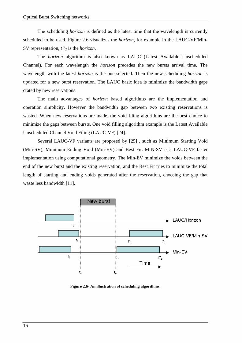
The scheduling horizon is defined as the latest time that the wavelength is currently
scheduled to be used. Figure 2.6 visualizes the horizon, for example in the LAUC-VF/Min-
SV representation, t’’2 is the horizon.
The horizon algorithm is also known as LAUC (Latest Available Unscheduled
Channel). For each wavelength the horizon precedes the new bursts arrival time. The
wavelength with the latest horizon is the one selected. Then the new scheduling horizon is
updated for a new burst reservation. The LAUC basic idea is minimize the bandwidth gaps
crated by new reservations.
The main advantages of horizon based algorithms are the implementation and
operation simplicity. However the bandwidth gap between two existing reservations is
wasted. When new reservations are made, the void filing algorithms are the best choice to
minimize the gaps between bursts. One void filling algorithm example is the Latest Available
Unscheduled Channel Void Filing (LAUC-VF) [24].
Several LAUC-VF variants are proposed by [25] , such as Minimum Starting Void
(Min-SV), Minimum Ending Void (Min-EV) and Best Fit. MIN-SV is a LAUC-VF faster
implementation using computational geometry. The Min-EV minimize the voids between the
end of the new burst and the existing reservation, and the Best Fit tries to minimize the total
length of starting and ending voids generated after the reservation, choosing the gap that
waste less bandwidth [11].
Figure 2.6- An illustration of scheduling algorithms.

Optical Burst Switching networks
17
2.8. OBS signaling schemes
This section is reserved for the OBS signaling schemes most commonly used, the Just
Enough Time (JET) and the Just In Time (JIT). It is presented the signaling messages flow
and other important information for these strategies.
2.8.1. Just-Enough-Time signaling scheme
The Just-Enough-Time (JET) signaling scheme is characterized by two main features,
namely, the DR (Delayed Reservation) and the ability to integrate the DR in Fiber Delay Line
(FDL)-Buffered Burst Multiplexers (BBMs). These features make the JET and the JET based
variations especially suitable for OBS networks when compared to other Tell and Go (TAG)
based OBS protocols and other one-way reservation based OBS protocols [1].
Figure 2.7 - JET signaling scheme flow.
Figure 2.7 presents the JET scheme packet flow. The JET reservation scheme starts
with the Control Packet transmission by the source node. All the intervenient nodes
Optical Burst Switching networks
18
electrically process the Control Packet to establish an all-optical path for the Burst
transmission. The information contained in the Control Packet is used to select the appropriate
wavelength on the outgoing fiber, reserve the necessary bandwidth and sets up the optical
switch. The Burst and the Control Packet are transmitted on the same path using different
wavelengths, (out of band signaling). During the reservation process, the source node retains
the Burst at an electric buffer.
Offset Time
The offset time is used to guarantee that the Burst is transmitted on the optical domain
without any delay along the entire path. It is used to the give enough time to the node
reconfiguration before the burst arrive.
In TAG based reservation schemes (Optical or Photonic Packet Switching) the burst is
transmitted by the source node with the Control Packet without using any offset time. In this
case at each intermediate node, the DB waits for the networks reconfiguration and both are
transmitted to the next node without use of any offset time. With this technique the Data Burst
and the Control Packet are delayed at each node Δ time units. Δ is the processing time used by
the nodes reservation.
In JET schemes a simple way to represent the offset time T is Tp×H, where Tp is the
Control Packet processing time at each node, and H is the number of hops used by the Burst
to connect the source to the end node. This technique guarantees that the offset time is enough
to the burst arrive at each node after it is prepared to transmit it in the optical domain without
the use of any optical buffer.
The Tp, above referred as processing time is more than the time used by the node to
process the Control Packet, it is also the time used to initiate other operations, such as
switching settings. After processing the Control Packet, it is transmitted to the next node
while the node initiates the configuration process.
Delayed Reservation for efficient Bandwidth utilization
The delayed reservation is useful for an efficient bandwidth usage. In TAG based
schemes, the bandwidth is allocated since the node finish the Control Packet processing,
Optical Burst Switching networks
19
while in JET the bandwidth can be allocated using the same technique, or using Delayed
Reservation (DR) for a better use of the bandwidth resource. Figure 2.8 illustrates this
process.
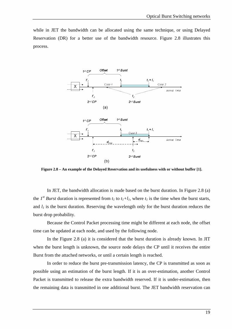
Figure 2.8 – An example of the Delayed Reservation and its usefulness with or without buffer [1].
In JET, the bandwidth allocation is made based on the burst duration. In Figure 2.8 (a)
the 1st Burst duration is represented from t1 to t1+l1, where t1 is the time when the burst starts,
and l1 is the burst duration. Reserving the wavelength only for the burst duration reduces the
burst drop probability.
Because the Control Packet processing time might be different at each node, the offset
time can be updated at each node, and used by the following node.
In the Figure 2.8 (a) it is considered that the burst duration is already known. In JIT
when the burst length is unknown, the source node delays the CP until it receives the entire
Burst from the attached networks, or until a certain length is reached.
In order to reduce the burst pre-transmission latency, the CP is transmitted as soon as
possible using an estimation of the burst length. If it is an over-estimation, another Control
Packet is transmitted to release the extra bandwidth reserved. If it is under-estimation, then
the remaining data is transmitted in one additional burst. The JET bandwidth reservation can
Optical Burst Switching networks
20
also be made to the infinite, and use an explicit relise packet when the transmission session
ends and the circuits are no more needed [1].
2.8.2. Just-In-Time reservation scheme
The Just In Time (JIT) OBS signaling scheme is an immediate reservation scheme
[26][27]. In the immediate reservation an output wavelength is reserved for the burst
transmission just after the Control Packet arrival (see Figure 2.9); if a wavelength cannot be
reserved at that time, then the Control message is rejected and the corresponding burst is
dropped.
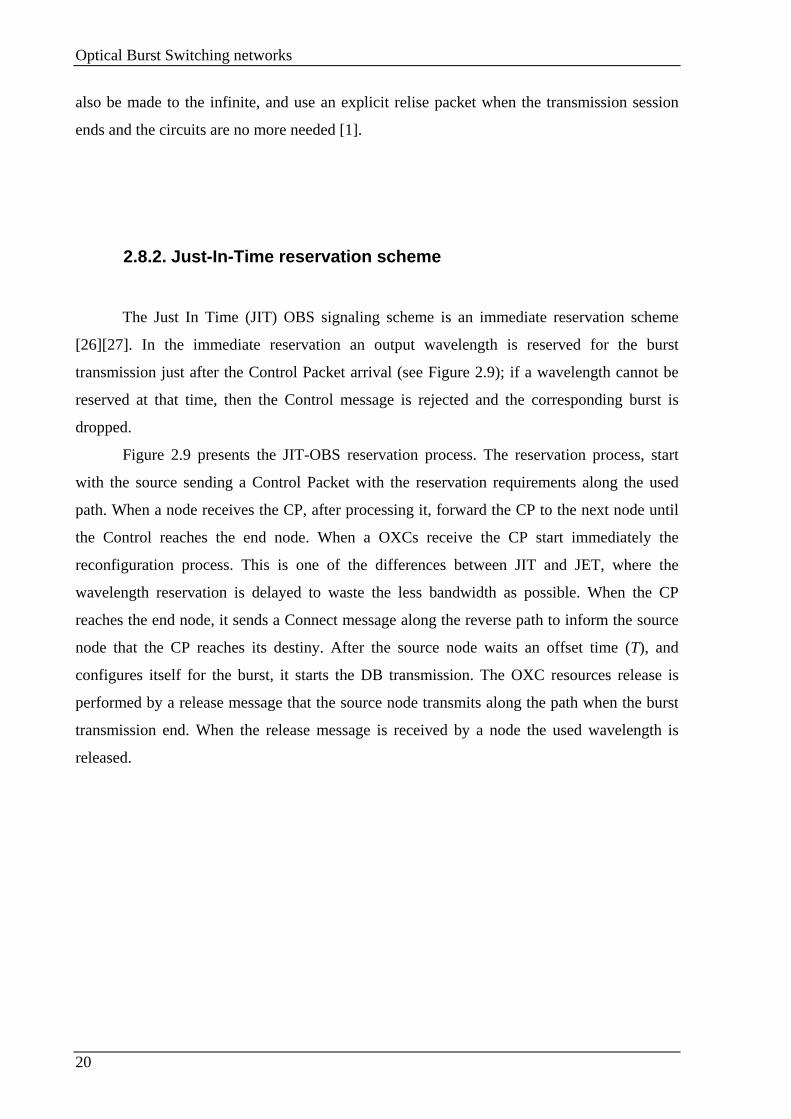
Figure 2.9 presents the JIT-OBS reservation process. The reservation process, start
with the source sending a Control Packet with the reservation requirements along the used
path. When a node receives the CP, after processing it, forward the CP to the next node until
the Control reaches the end node. When a OXCs receive the CP start immediately the
reconfiguration process. This is one of the differences between JIT and JET, where the
wavelength reservation is delayed to waste the less bandwidth as possible. When the CP
reaches the end node, it sends a Connect message along the reverse path to inform the source
node that the CP reaches its destiny. After the source node waits an offset time (T), and
configures itself for the burst, it starts the DB transmission. The OXC resources release is
performed by a release message that the source node transmits along the path when the burst
transmission end. When the release message is received by a node the used wavelength is
released.
Optical Burst Switching networks
21
Figure 2.9 – JIT signaling scheme flow
The wavelength release is another difference between the JIT and JET. In JET the
release is normally programmed, when the reservation timer finishes the wavelength is
released, while in the JIT, the wavelength is released using an explicit release message
transmitted by the source node.
Another immediate reservation representation performed by JIT is represented by
Figure 2.10. Figure 2.10 presents two bursts reserved in a single wavelength. There are two
states, reserved or free, after the node receives the setup message (Figure 2.9 Control
message) and reconfigure itself, the wavelength status pass automatically from free to
reserved, and just after receiving the release message, the wavelength status pass to free again.
In Figure 2.10 the wavelength is reserved between t1 and t3 and between t4 and t6,
corresponding to the bursts i and i+1 transmission. The reservation process is a First Come
First Served (FCFS); the burst is dropped when the new reservation time is in a wavelength
time slot already reserved.
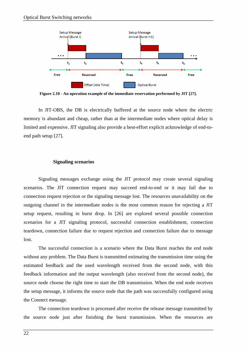
Optical Burst Switching networks
22
Figure 2.10 - An operation example of the immediate reservation performed by JIT [27].
In JIT-OBS, the DB is electrically buffered at the source node where the electric
memory is abundant and cheap, rather than at the intermediate nodes where optical delay is
limited and expensive. JIT signaling also provide a best-effort explicit acknowledge of end-to-
end path setup [27].
Signaling scenarios
Signaling messages exchange using the JIT protocol may create several signaling
scenarios. The JIT connection request may succeed end-to-end or it may fail due to
connection request rejection or the signaling message lost. The resources unavailability on the
outgoing channel in the intermediate nodes is the most common reason for rejecting a JIT
setup request, resulting in burst drop. In [26] are explored several possible connection
scenarios for a JIT signaling protocol, successful connection establishment, connection
teardown, connection failure due to request rejection and connection failure due to message
lost.
The successful connection is a scenario where the Data Burst reaches the end node
without any problem. The Data Burst is transmitted estimating the transmission time using the
estimated feedback and the used wavelength received from the second node, with this
feedback information and the output wavelength (also received from the second node), the
source node choose the right time to start the DB transmission. When the end node receives
the setup message, it informs the source node that the path was successfully configured using
the Connect message.
The connection teardown is processed after receive the release message transmitted by
the source node just after finishing the burst transmission. When the resources are
Optical Burst Switching networks
23
successfully tear down, the node transmits for the previous node a packet informing a
successful tear down.
When the setup packet does not reach the end node, the burst is drooped. In this case,
the node is unable to continue the circuit transmits in the reverse path a release packet. The
source node start the burst transmission using the estimated delay, when the burst is
transmitted before it receives the realise message, the data is dropped when reaches the node
unable to retransmit the setup. When the source node receives the release packet it can retry
the connection or abort the connection request.
The connection failure due to message lost occur when the setup packet is lost in a link
between two nodes or one of the signaling agents has crashed and is unable to respond. If this
occurs after the second node, the start node receives the packet with the necessary information
used to start the burst transmission. In this case, the DB is transmitted and dropped on the
unconfigured node. Eventually the source node detects that it did not receives the Connect
message from the end node it start the network resources release transmitting along the path a
Release Comp. Again there is no automatic recovery support from the signaling protocol, and
it is the source node that select retry or abort the connection.
2.9. OBS Applications
Before the OBS technology development, burst switching concept had been proposed
as an extension of packet switching. Basic advantages present in burst switching are reducing
loop length and increasing data rate transmission [28]. OBS networks are a burst switching
extension for optical networks. The main motivation for the OBS creation is to reduce (or
even eliminate) the need of optical buffering, as well as minimizing the network overhead [5].
One application is distributed database, where OBS can achieve efficiently assemble
data and path setup while the network overhead is reduced.
Another attractive area where OBS has been considered as an effective underlying
technology is Grid Computing as a mean of providing global distributed computing for
applications with large bandwidth, storage and computational requirements

Optical Burst Switching networks
24
2.10. Chapter summary
In this chapter an overview about the OBS technology was presented. OBS networks
are an appropriate technology to use in long haull networks with limited delay requirements.
An advantage of OBS is the out-of-band signaling. Using the out-of-band signaling it is
guaranteed that the Control Packets reach the end node even when the data channels are
strangled. In OBS networks, Burst Control Packets is transmitted in advance to prepare the
network resources for the Data Bursts transmission. Usually OBS networks use one-way
reservation schemes, which the drawback of OBS technology, because the DBs are
transmitted without knowing that the path were successfully reserved. The One way
reservation protocol does not present only disadvantages, this technique allow lower networks
setup latency.

Grid over OBS network architectures
25
Chapter 3. Grid over OBS network architectures
3.1. Introduction
In this chapter Grid over OBS (GOBS) are introduced. First, Grid networks functions
and architecture are presented followed by the introduction of Grid over OBS networks.
3.2. Grid
A Grid network is a flexible and distributed information technology environment that
enables the creation of multiple services with a significant degree of independence from the
specific attributes of underlying support infrastructure [29].
Initially, Grid infrastructures where designed to support and compute intense science
projects. With the technological evolution, nowadays, Grids support several different services
with an abstraction level that make possible support an almost unlimited number of services
without the dependencies restrictions inherent to the delivery mechanisms, local sites or
particular devices.
3.2.1. Grid networks attributes
The Grid network attributes are used to guarantee that the network resources are
closely integrated in the Grid environment. The attributes are the following [29]:
Abstraction- One of the most important Grid features is the abstraction capability to
underlying resources and integrates Grid capabilities to support customized services. Grid
architectural model presupposes an environment in which available modular resources can be
detected, gathered and utilized without any restriction imposed by low level infrastructures.

Grid over OBS network architectures
26
This architecture does not specify the possible resources complete details; it describes the
classes of Grid Components requirements.
Resources virtualization is a powerful tool for creating advanced data network
services. The major advantage to the Grid Network virtualization through abstraction
techniques is increase the flexibility in service creation, provisioning and differentiation. It
allows specific application requirements to be more directly matched with network resources.
Virtualization also enables networks with very different characteristic to be implemented
within a common infrastructure, and enables network processes and resources to be integrated
directly with other types of Grid Resources.
Using high-level abstraction for network services and integrating network capabilities
through Grid middleware provides to Grid Computing flexibility that it is not possible to
achieve with traditional data networks. Traditional data networks support only a limited range
of services, because they are based on rigid infrastructure and topologies, with restricted
abstraction capabilities.
Resource sharing- The entities responsible to Grid Networks development are
engaged to implement Grid infrastructures software with web services components. The Web
service components have the function to enable the access to sets of building block that can be
combined easily into different services combination. One example of this is the Web Service
Resource Framework (WSRF) created by the Global Grid Forum (GGF) [30].
Flexibility through programmability- The programmability provides a more flexible
environment to Grid networks. Only recently the flexibility became a Grid network
characteristic, because previously the network infrastructure was designed to support static
services with fixed parameters. In the last few years, several initiatives to crate Gird
architectures with a more flexible communication services were made. Using those methods,
Grid networks can be provisioned as programmable, allowing dynamic services changing and
resource allocation with dynamic reconfigurations.
Determinism in network services- Determinism is the ability to request and receive
required resources and to define precisely matching service levels. The primary Grid network
research goal is create more diverse communication services, including services that are more
deterministic and adjustable, not only for the most commonly use. Deterministic networking
is important to achieving optimal application performance and is also a technology that

Grid over OBS network architectures
27
enables many classes of applications that cannot be supported through traditional QoS
mechanisms. This capability includes mechanisms for requesting individual network services
with specific set of attributes and when is required reconfigure the network resources to
obtain those specific services.
Decentralized management and control- An important Grid environment capability
is the decentralized control and resources management. This decentralization allows the
resource provisioning, utilization and reconfiguration without the intersection of the
centralized management or other authorities. Emerging Grid networking techniques define
methods that provide determinism allowing applications to have precision control over
network resource elements when required.
Dynamic integration- The Grid architecture was designed to allow an expansive set
of resources to be integrated into a single, cohesive environment. The integration can be made
in advance, usually is a challenge making the integration in architectures that require real time
ad-hoc changes, because networks was not designed for dynamic reconfiguration. However
new architectures and techniques enable communication services and network resources to be
integrated with other Grid resources and continually changed dynamically.
Resource Sharing- The primary motivation for design and Grid architecture
development is enhance the resource sharing capabilities, for example, spare computation
cycles for multiple projects utilization [31]. The major advantage of Grid networks is the
option provided for resource sharing, that are very difficult, if not impossible, to implement in
traditional data networks. The networks resources virtualization allows the new Grid network
to create resource sharing facilities that have not been possible to implement until recently.
Scalability- The scalability can be referred in many ways, the expansion over the
geographical locations, enhanced performance, increase the number of services offered and
the communities served, etc. By definition, Grid environments are highly distributed and
therefore highly scalable geographically. Grid networks can be geographically extended since
metro networks, passing trough regions or nations, but Grid networks can also be world-wide.
The advanced Grid networks scalability has been tested by global science applications on
high-performance international research and education. The scalability was tested at the
infrastructure and service level.

Grid over OBS network architectures
28
High performance- Because many Grid applications are extremely resource intense,
Grid networks requires extremely high-performance capabilities to support data-intensive
flows that cannot be supported by traditional networks.
Security- Security has always been a high-priority requirement that has been
continually addressed by Grid developers [32]. To guarantee that Grid networks are highly
secure, new techniques are being produced. For example different types of segmentation
techniques used for Grid network resources, especially at the physical level, allow high-
security data traffic to be completely isolated from other types of traffic. Also recently new
techniques of encrypting data ensure security levels difficult to obtain in traditional networks.
Pervasiveness- Grid environments are extensible to wide geographic areas, including
distributed edge devices. Grid network services are designed for ubiquitous deployment,
including as overlay services on flexible network infrastructure. Multiple research and
development projects are focused on extending Grids using new types of edge technologies,
such as wireless broadband and edge devices, including consumer products, mobile
communication devices, sensors, instruments and specialized monitors.
Customization- New Grid architecture and methods provide the creation and
implementation of multiple customized Grid communication services that can be
implemented within a common infrastructure. Grid networks based on capabilities for
adaptative services, resource abstraction, flexibility and programmability can be used to create
many types of communication services that were not possible have in than traditional
networks.
3.2.2. Grid standards
Several entities are responsible to develop standards for Grid networks. This section
presents these entities Grid projects.
The Global Grid Forum (GGF) [30] is a company which the main objective is the
Grid-related standards. The GGF is responsible for several highlighted documents, see [29].
Grid over OBS network architectures
29
One of the GGF highlighted documents is the Open Grid Services Architecture (OGSA) [33].
OGSA articulate eight categories of services (infrastructure, resources management, data,
context, information, self-management, security services and execution management) used to
obtain a shared, secure and dependable access to available Grid resources. WS-Agreement
[34] is another GGF highlighted document WS-Agreement is a design pattern that defines
how the service producer and the consumer can reach an agreement.
Several Grid vendors and customers have organized a consortium which considers the
many facets of Grid adoption within an enterprise. The consortium is called Enterprise Grid
Alliance (EGA) [29].
The World Wide Web Consortium (W3C) [35] is an entity responsible for
specification, guidelines, software and tools used in the World Wide Web. W3C develop
specifications like XML (Extensible Markup Language) [36], SOAP (Simple Object Access
Protocol) [37] and WSDL (Web Services Description Language) [38] that are the foundation
for Grid toolkits as well as other web services applications.
In IPSphere forum [39], network vendors and providers have converged to define an
intercarrier automation tool for policy, provisioning and billing settlement. The IPSphere
objective is search for strategies to resolve providers long standing difficulties in obtaining
financial returns from QoS service classes stretching across multiple providers.
Other standards bodies such as: Message Passing Interface (MPI) Forum [40];
Distributed Management Task Force (DMTF); Common Information Model (CIM) [41] the
International Telecommunication Union (ITU) [42] and the Institute of Electrical and
Electronics Engineers (IEEE) [43] have also Grid projects.
3.3. Grid over OBS
OBS networks supporting Grid networks present several advantages, such as:
• Native mapping between burst and Grid jobs. OBS networks offered a bandwidth
granularity that permit a efficient users jobs transmission with different traffic
profiles;
• Data and control plain separation allow an all optical data transmission with ultra-
fast user/application-initialized setup;
Grid over OBS network architectures
30
• The BCP electronic processing at each node which can enable the network
infrastructure to offer Grid protocol layer functionalities (e.g. intelligent resource
discovery and security).
3.3.1. Grid OBS network elements
Core OBS router: OBS relies on fast switching technology and a relatively slow
setups times (milliseconds rather than nanoseconds). This setup time are small compared to
the payload durations, normally hundreds of milliseconds or seconds.
The introduction of Grid services over OBS networks require some constrains for the
switching speed requirements, which became particularly important when high speed
transmissions are considered.
A flexible Grid network will require also to support user with small job requests.
Small jobs (100 to 1000 bytes) require an ultra fast switching, in nanoseconds. It is
particularly advantageous to use multicasting to enable parallel Grid processing services as
well as the resource discovery [45]. For these reasons the fast switching technology
deployment is essential for future high speed OBS networks with support for Grid
applications. Grid Core OBS Routers require control information and BCP intelligent
processing, which can only be performed using specially designed fast electronic circuits.
Recent advances in the integrated circuits technology allow complicated processing of bursty
data directly up to 10 Gbps [46].
High transmission rates used by the BCP and the control information enable
transparency during the burst switching (i.e. no conversion to the electric domain). The
optical bursts can be transmitted at ultrahigh bit rates (40 or 160Gb/s), providing by the
switching elements that can support these bit rates. These high bitrates need fast active
elements, like Semiconductor Optical Amplifier (SOA). The switching process consists in
broadcasting the signal and selects the appropriate route using fast gating or converting the
signal wavelength and routing to the appropriate passive routing device (Arrayed Waveguide
Grating (AWG)) output port [44].
Fast switching allows efficient bandwidth utilization. Fast switching does not give any
advantages when it used in long bursts, e.g. burst originated by large Grid clients. A proper
solution for OBS networks is a fast and slow switching combination. For example the fast
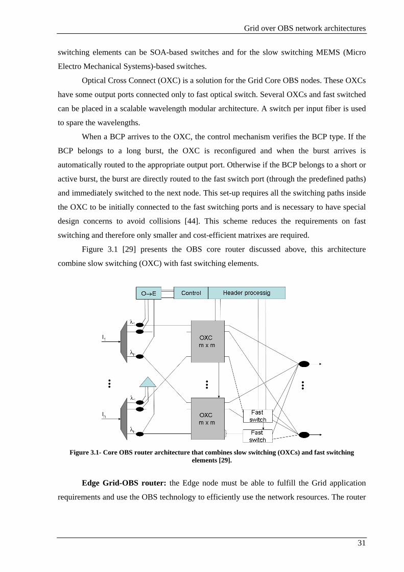
Grid over OBS network architectures
31
switching elements can be SOA-based switches and for the slow switching MEMS (Micro
Electro Mechanical Systems)-based switches.
Optical Cross Connect (OXC) is a solution for the Grid Core OBS nodes. These OXCs
have some output ports connected only to fast optical switch. Several OXCs and fast switched
can be placed in a scalable wavelength modular architecture. A switch per input fiber is used
to spare the wavelengths.
When a BCP arrives to the OXC, the control mechanism verifies the BCP type. If the
BCP belongs to a long burst, the OXC is reconfigured and when the burst arrives is
automatically routed to the appropriate output port. Otherwise if the BCP belongs to a short or
active burst, the burst are directly routed to the fast switch port (through the predefined paths)
and immediately switched to the next node. This set-up requires all the switching paths inside
the OXC to be initially connected to the fast switching ports and is necessary to have special
design concerns to avoid collisions [44]. This scheme reduces the requirements on fast
switching and therefore only smaller and cost-efficient matrixes are required.
Figure 3.1 [29] presents the OBS core router discussed above, this architecture
combine slow switching (OXC) with fast switching elements.
Figure 3.1- Core OBS router architecture that combines slow switching (OXCs) and fast switching
elements [29].
Edge Grid-OBS router: the Edge node must be able to fulfill the Grid application
requirements and use the OBS technology to efficiently use the network resources. The router
Grid over OBS network architectures
32
architecture should introduce a mechanism able to process Grid-IP traffic for Grid
Differentiated Services (GridDiffServ) provisioning and maps it onto optical burst [44].
An Edge Grid-OBS Router must be able to perform the follow functionalities:
• Grid Job Classification;
• Traffic aggregation and optical burst assembly;
• Optical burst transmission;
• Grid user to network as well as Grid resource to network signaling;
Grid Job Classification- The Edge OBS node at the job classification process must
provide fair and specialized services (GridDiffServ). The Application performance and Grid
network utilization can be enhanced by a combination of computational and network
resources to user/application requirements. A flexible and scalable Grid job classifications
mechanism process the jobs based on Grid requirements The jobs classification combines
independently three parallel processing schemes, Network-oriented Classification Scheme,
Grid Oriented Classification Scheme and Time Oriented Classification Scheme. These
classifications schemes are all synchronized and are triggered only by Grid Job Requests. The
job classification speed is vital for providing intelligent services the Edge Router. The
classification process is complex and time consuming, efficient queuing schemes as well as
wire speed classification became important factors to avoid buffers overflow at the Edge
Routers [44].
Burst Aggregation- The burst aggregation features in the Grid-OBS Edge Routers are
the same that are used by the OBS nodes. These features are discussed in the section 2.6 of
this dissertation.
To facilitate the on demand access to Grid services is necessary to develop
interoperable procedures between the Grid user and the optical network for agreement
negotiation and Grid service activation. These processes constitute the Grid User Optical
Network Interface (G-OUNI or GUNI). The G-OUNI functionalities and implementation will
be influenced by the following parameters [44]:
• Service invocation scenarios: the request form the user can be from the optical
network control plane either directly or through Grid middleware[47];
Grid over OBS network architectures
33
• Two-Optical transport format, which determines transmission format of the
signaling and control messages as well as data from Grid user to optical
network [29].
The main functionalities provided by the GUNI in a Grid over OBS network are the
following:
• Flexible bandwidth allocation: the GUNI support various bandwidth services;
• Support for claiming existing agreements: GUNI must facilitate the incorporation of
information that relates to an existing agreement. This covers the support of lambda
time-sharing mechanism to facilitate bandwidth scheduling over a time slot for a Grid
user/service (i.e. wavelength times sharing for an efficient and low cost bandwidth
utilization). The GUNI signaling will also be required to bandwidths ownership
support and the transport of authentication and authorization-related credentials;
• Automatic and timely lightpath setup: Grid user use the GUNI to automatically
schedule, provisioning and setup ligthpaths across the network;
• Traffic classification, grooming, shaping and transmission entity construction: the
GUNI must be able to at the transport layer (physical layer), map the data traffic to a
Data Burst. In the in-band signaling, the GUNI provide a mapping mechanism for the
control messages transmission.
In Grid networks, Grid resources (i.e. storage and processing) are geographically
distributed along the networks. Grid Resources can dynamically enter and leave the OBS
network based on pre-established agreements. These Grid resources are denominated Grid
Resources Network Interfaces (GRNI). A dedicated signaling and control interface is used
between the Grid resources and the Grid network. Like GUNI, the GRNI must perform
interoperable procedures between external networks and the OBS networks. Unlike GUNI,
the GRNI interfaces are placed between the resources (processing and/or storage distributed
across the network) and the optical network. The similarity between these two elements
(GUNI and GRNI) make possible extend the GUNI model to provide required functionalities
for the resource network interface.
In Figure 3.2 present a Grid over OBS network with OBS routers. The OBS router can
perform only the OBS functionalities or can perform the OBS functionalities and also Grid
functionalities. The job resources are represented as GRNIs and the Grid users are represented
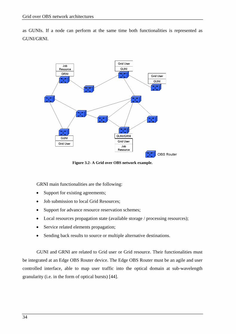
Grid over OBS network architectures
34
as GUNIs. If a node can perform at the same time both functionalities is represented as
GUNI/GRNI.
Figure 3.2- A Grid over OBS network example.
GRNI main functionalities are the following:
• Support for existing agreements;
• Job submission to local Grid Resources;
• Support for advance resource reservation schemes;
• Local resources propagation state (available storage / processing resources);
• Service related elements propagation;
• Sending back results to source or multiple alternative destinations.
GUNI and GRNI are related to Grid user or Grid resource. Their functionalities must
be integrated at an Edge OBS Router device. The Edge OBS Router must be an agile and user
controlled interface, able to map user traffic into the optical domain at sub-wavelength
granularity (i.e. in the form of optical bursts) [44].
Grid over OBS network architectures
35
3.3.2. OBS for consumer Grid applications
The Optical Circuit Switching (OCS) is the network solution currently used. OCS
networks are unsuited to provide Grid services. The dedicated infrastructures are wasteful and
inflexible, while request/grant architectures with Grid resources electronic management are
too complex. OBS is a possible technology to solve these problems because it is suitable to
tasks with low processing, high resource utilization and simple control.
In OBS networks it is assumed that the shortest routing paths are used to minimize the
end-to-end delay. However, such networks can be inefficient, since certain links might have a
low usage, while others became severally congested, which leads to sub-optimal network
performance. This is especially visible when the main metric is the burst dropping probability,
as it is usual in OBS networks. The solution proposed to resolve this problem in OBS is
deflection routing and multi-path routing, but in both cases, the sender and the receiver are
usually known in the data transfer. In Grid OBS networks the destination is not always
known.
In Grid consumer scenarios it does not matter where the job is processed. The same
job may have several destinations. The user is only interested in the job being resolved
respecting its requirements. This represents a shift in the nature of the employed routing
algorithm, whereas previously bursts had an exact destination (unicast routing), in this
scenario, the only requirement is the burst transmission to any node capable to resolve it, this
strategy is named anycast routing [2][48][49].
When a node is not able to resolve a job, it require to Grid services to resolve the job
and accelerate this process. Initially the job is transformed in an optical burst (DB),
accomplished by a header (BCP) with various burst parameters, such as processing, storage
and policy requirements. The burst parameters carried by the header are used for the network
resources configuration. When a burst arrive to a router, it retransmit it on the fly to the next
router based on the job header and on the network status information, until the job arrive to
the node responsible to resolve it. The information used by the router to select the next node is
for example the link load and blocking probability, delay requirements, estimated free
computing storage capacity reached for a certain interface, estimated computing and storage
requirements of the burst. Because the end node is unknown at the beginning, the Grid
architecture need to be completely distributed, which implies better network scalability and
robustness. The information use by the intermediate nodes to select the next one does not
Grid over OBS network architectures
36
need to be very detailed. They do not need to know where the resources are located, or how
much free resources have. They only need enough information to push the burst closer to a
suitable destination.
Every intermediate node goes through the same process, and eventually when the burst
arrive to the Grid resource, if it is able to resolve the burst it will process it. Otherwise, the
burst is transmitted to the OBS network until it reach a Grid resource able to resolve it or the
burst is dropped if exceed the useful time to be processed.
With the job resolved, the result returns to the source node. Because the node that
starts the job is already known, the result is directly transmitted to the burst source node. The
used path depends on various factors, for example, if is a real time job, the result is
transmitted using the shortest time path possible, otherwise if is an offline, it can return to the
source node using a longer path. The fact that from the source to the Grid resource is used
anycast and in the reverse way the data is transmitted directly to the source node, this is an
example of the asymmetry in Grid OBS consumer scenarios.
The Consumer Grid network robustness is usually measured in job blocking
probability. The resources unavailability is the cause for dropping the jobs. The resources
unavailability can be network resources (i.e. links and routers) or server resources (i.e.
processing elements).
Robustness in the networks can be introduced using two methods:
• Spare capacity: before the deployment, the network is usually dimensioned based
on the load estimation or experienced job requests. Once is necessary to introduce
more network or resource servers, there are only introduced only the necessary
ones;
• Duplicate submission: if the same job is transmitted to the network more than
once, the possibility of it reaches different recourses, or the same recourse using
different path is non-negligible. This method introduces robustness in Grid OBS
networks. But use more capacity than the necessary.
The consumer Grid network must be able to support all application types, because is
not economical create a Grid network for each application. A network that supports all
applications types use different resource patterns to differentiate each one. The infrastructure
should offer relatively simple components and sufficient flexibility to deploy new
applications quickly and efficiently. It will also need to support traditional OBS users
Grid over OBS network architectures
37
requiring a plain data transfer functionality, whereby the burst contain, for instance Grid
Packets instated of Grid jobs [2].
The authors of [2] propose the following proprieties of the job-generation process in
consumer Girds:
• A large number of jobs are generated;
• Each job have modest resource requirements;
• The job sizes are small, introducing small holding times compared to optical
switching times;
• The job submission time and location are highly unpredictable. This result in
frequent mismatches in available versus generated load.
• Several application types will be interactive in nature, indicating a strict deadline
must be met for a successful completion. While other have a less restrict
requirements. This means that are considered several QoS classes.
3.4. Chapter summary
This chapter presents an overview of Grid networks, and Grid over OBS networks
features. Grids provide computational distributed resources (storage and processing). Grid
over OBS networks extend the Grid functionalities to an OBS network, using the OBS
network to resolve the Grid jobs Recently the Grid features were extended to commercial
applications, which require low computational resources. In a GOBS consumer scenario, the
OBS network is used to provide a Grid resource to resolve the consumer jobs. The consumer
jobs require low computational resources and usually have small durations. The work
presented in this master dissertation is based on a GOBS consumer scenario.

Grid over OBS network architecture using Active Routers
39
Chapter 4. Grid over OBS network architecture using Active Routers
4.1. Introduction
Optical network resources reservation is a complex process that usually involves
several entities cooperation.
The problem of offering optical network resources as Grid services has been
considered in [54]. Where three different approaches have being proposed:
a) the Grid management and the optical-layer resources are considered separately
using an overlay model;
b) extended model where the optical control plane integrates Grid resources
provisioning;
c) and OBS network that use Active OBS Routers
The work presented in this dissertation considers a Grid over OBS network employing
Active Routers.
4.2. Active OBS infrastructure for Grids
The networks proposed by [2] and [50] are an OBS network architecture composed by
Active and non Active OBS Routers. The non Active Routers are conventional OBS routers
and perform burst forwarding according to the information contained in the BCP. The Active
Routers intercept the data carried by the Active Packets, which packets specific of Grid
applications and perform dedicated Grid networking functions. In a Grid over OBS network
with Active Routers, both traditional data and Grid traffic are supported. All OBS nodes can
perform burst forwarding when the normal traffic transits across the network while the Grid
traffic is supported by the Active Routers.

Grid over OBS network architecture using Active Routers
40
The network topology represented in the Figure 4.1 is very similar to the one proposed
by [2] and [50], a network with conventional OBS Routers and Active OBS Routers. Each
Active OBS Router is responsible for one Active region having the complete knowledge of
the region topology and all nodes and links actual status. The Active Router is also
responsible for the Grid resource discovery. Grid users can be Grid resource users with a Grid
User Network Interface (GUNI). Grid resource providers with a Grid Resource Network
Interface (GRNI) or users with both GUNI and GRNI interfaces can perform both
functionalities.
Figure 4.1 - Active OBS network topology for Grid services.
Signaling scheme in the Figure 4.2 present the signaling scenario proposed by [2] and
[50]. This strategy is based in the JET OBS signaling scheme. The JET reservation scheme is
the most appropriate protocol for the Grid Architecture employing Active Routers [51],
because with JET, the resources are reserved just before the DB arrive and only for its
duration.
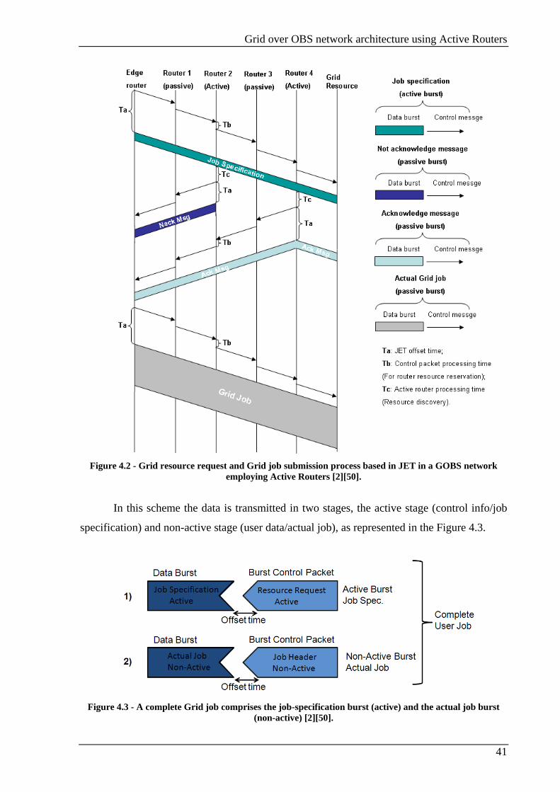
Grid over OBS network architecture using Active Routers
41
Figure 4.2 - Grid resource request and Grid job submission process based in JET in a GOBS network
employing Active Routers [2][50].
In this scheme the data is transmitted in two stages, the active stage (control info/job
specification) and non-active stage (user data/actual job), as represented in the Figure 4.3.
Figure 4.3 - A complete Grid job comprises the job-specification burst (active) and the actual job burst
(non-active) [2][50].

Grid over OBS network architecture using Active Routers
42
The user sends to the Edge Router a request containing information about the Grid job
specification and the resource requirements. The Edge Router constructs the Active Burst
Control Packet (se Figure 4.3-1) and transmits it. The Active Burst Control Packet is
processed at the Active Routers. Once the Active Router receives the Grid job specification it
starts the resource discovery algorithm to find out whether there are enough Grid Resources
available in its Active domain able to perform the required job.
The users are informed about the resource discovery process by an Acknowledgement
if exists a resource able to resolve the job, otherwise a Non Acknowledgement is transmitted.
This signaling reservation scheme consists of two steps as indicated in Figure 4.2:
1. A BCP Active Burst is transmitted to all Active Routers through intermediate
nodes (active and non active). The BCP is transmitted to the network an offset
time before the DB transmission. At each Active Router, resource discovery
algorithm results in the creation of an Acknowledgement (Ack) or a Non
Acknowledge (Nack). These messages are transmitted back to the user after
through a non-active optical burst. If a positive Acknowledgement is
transmitted, the Active OBS Router informs the corresponding resource
manager. From this moment the resource manager reserves the resource for a
limited period of time.
2. After receiving all the Ack or Nack messages, the source node select one or
multiple appropriate destinations among all the available. The actual job is now
transmitted within the reservation period to the destination using a non active
optical burst format.
This scenario provides high bandwidth utilization, especially when large bursts need to
be transmitted, because the data is only transmitted though the networks after the resources
have being reserved. Stages networking scheme offers an intelligent and user controlled Grid
resource utilization through the active OBS stage, while in the non active OBS stage the Grid
is established instantly after the resource discovery process. It also provide a secure and
policy based Grid environment where the users can select the Grid resource in different
domains across the network. One important advantage is that, after the resource discovery,
there is no more delay associated to the wavelength path setup.
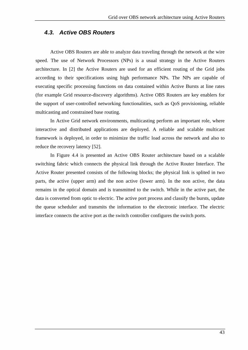
Grid over OBS network architecture using Active Routers
43
4.3. Active OBS Routers
Active OBS Routers are able to analyze data traveling through the network at the wire
speed. The use of Network Processors (NPs) is a usual strategy in the Active Routers
architecture. In [2] the Active Routers are used for an efficient routing of the Grid jobs
according to their specifications using high performance NPs. The NPs are capable of
executing specific processing functions on data contained within Active Bursts at line rates
(for example Grid resource-discovery algorithms). Active OBS Routers are key enablers for
the support of user-controlled networking functionalities, such as QoS provisioning, reliable
multicasting and constrained base routing.
In Active Grid network environments, multicasting perform an important role, where
interactive and distributed applications are deployed. A reliable and scalable multicast
framework is deployed, in order to minimize the traffic load across the network and also to
reduce the recovery latency [52].
In Figure 4.4 is presented an Active OBS Router architecture based on a scalable
switching fabric which connects the physical link through the Active Router Interface. The
Active Router presented consists of the following blocks; the physical link is splited in two
parts, the active (upper arm) and the non active (lower arm). In the non active, the data
remains in the optical domain and is transmitted to the switch. While in the active part, the
data is converted from optic to electric. The active port process and classify the bursts, update
the queue scheduler and transmits the information to the electronic interface. The electric
interface connects the active port as the switch controller configures the switch ports.

Grid over OBS network architecture using Active Routers
44
Figure 4.4- A generic model for an Active OBS Router [50].
4.3.1. Resource discovery mechanisms
The resource discovery and allocation is facilitated by Grid job classification
mechanisms. The active bursts contain the information used to determine the jobs
requirements. The classification triggers the Active Routers intelligent mechanisms (job
scheduling, queuing and resource discovery), for GridDiffServ provisioning. The Grid job
parameters that mostly affect the resource discovery are the resource requirements,
parallelism and priority.
The resource requirements are the period of time and the speed that the job requires to
be processed. The job requirements also identify the type of resource (storage or processing)
to be allocated and efficiently serve these demands.
Parallelism determines the types of applications program and data. Each application
type has different requirements for optimal performance. Granularity and communications
frequency between these programs specifies the nature of application distribution approach is
affected by the applications programs dependency [53].
Priority is photonic Grid networks is considerably different than the priority concept in
traditional photonic networks. For example, the requests made by resource members have
always higher priority than the ones performed by non-members. The requests with less

Grid over OBS network architecture using Active Routers
45
priority are made by unauthorized users. Priority triggers the Grid authorization policies and
prompts the scheduler to decide on appropriate resources for efficient resource reservation
and allocation.
This classification schemes can significantly improve the performance by scaling the
applications out to as many resources on the Grid. Class of service ensures that the resources
are optimally matched to applications needs and thus improve Grid and network performance.
The class ID takes account the Gird job parameters (resource requirements, parallelism and
priority) and drives the subsequent processes for GridDiffServ provisioning [50].
The burst classification speed is vital for provisioning an intelligent service at the
router level. Lack of wire speed classification will result in queuing active bursts before they
are processed. Important traffic will be dropped, or unfair queuing will occur [54].
4.4. Chapter summary
This chapter presents the Grid over OBS networks employing Active Router and the
signaling performed for these networks.
The final section of this chapter was dedicated to resource discovery, which is one of
the Active Routers functions.

Proposed signaling reservation schemes for Grid over OBS
47
Chapter 5. Proposed signaling reservation schemes for Grid over OBS
5.1. Introduction
This chapter describes the signaling scheme proposed in this work. The application
scenario considered is a Grid over OBS network with Active Routers. The signaling scheme
is a centrally controlled Wavelength Routed – Optical Burst Switching (WR-OBS) scheme,
where the Active Router acts as the control node [63][64].
In order to clarify the operation of the proposed scheme, it is compared with a JET-
OBS modified version. The JET-OBS modified version is an adaption of the usual JET (see
section 2.8.1) for a Grid over OBS network controlled by Active Routers.
5.2. Signaling Scheme description
Dynamic connections request in the WR-OBS networks can be handled in a
distributed or centralized way. In the centralized manner, the network information is available
at a single point in the network and the lightpath establishment is made in a more efficient
way, as long at the optical networks remain small, this is because large networks create a
great quantity of information to be processed in a single point. However, either in the
centralized or distributed control, the ability to update global network information about link
connectivity and wavelength availability is very important.
In a centralized WR-OBS, the control node is responsible for setup and tear down its
administrative domain lightpaths. In the WR-OBS, the central node selects the best path for
each job using its full knowledge about the network link state. In the proposed WR-OBS
scheme, the central control is performed by an Active Router with its Active Region global
knowledge (networks connectivity, links and nodes status). The Active Router correlates all
that information to select the best Grid job Provider and the best path to reach it.

Proposed signaling reservation schemes for Grid over OBS
48
5.2.1. Packet description
The proposed signaling scheme is composed by three basic signaling control packets,
the BCPA, OXC_config and ACK. Figure 5.1 illustrates the packet fields structure. The
Control Packet, Figure 5.1 (a), is the reference packet with general fields used by BCPA,
OXC_config and ACK that are encapsulated in the Information Field.
In Figure 5.1 (a), the BCP TYPE is used to identify which packet type is encapsulated
in the Control Packet (BCPA, OXC_config and ACK), the Time To Live (TTL) field represent
the maximum number of hops, this field is used to guarantee that the packets do not travel in
the network to the infinity wasting networks recourses. CHEK SUM is used to verify the
packet integrity after the transmission and the FRAMING HEADER contains information like
the source node, which wavelength is used, etc.
BCPA, Figure 5.1 (b), is the Control Packet description; it is used by the source node to
request to the Active Router a Grid job resource and the best path to reach it. The Message ID
and Job ID are used to identify the message and the job (this fields are used by the routers to
avoid processing the same packet more than once). Source is the source node identification;
Duration is the time that the network resource needs to be reserved for this specific job and
the Class of Service is used to classify the job in terms of class. The class classification
enables attribute QoS levels to the network.
Figure 5.1 (c) illustrates the OXC_config structure. This packet is used by the Active
Router to configure the nodes and reserve the wavelength along the used path. Destination,
Job ID and Duration fields have the same functionality that in the BCPA packet. The Ingress
Port and Egress Port fields are filed with respectively the ingress and egress ports that will be
reserved for the respective this job, the wavelength is the wavelength used by the job along
the path. In this scheme is considered a non wavelength conversion strategy, when the chosen
wavelength is not free along the path, the job is dropped. The Offset is the compensation time
used by the start node. This offset is used to avoid that the node is not prepared for the job,
this OBS network characteristic is explained with more detail in section 2.5.
The ACK is represented in Figure 5.1 (d). This packet has the same fields as the
OXC_config plus one, the Job resource, contains the places where the job is resolved, this
message is used to inform the source node where job is resolved and which path is used to
reach it.

Proposed signaling reservation schemes for Grid over OBS
49
Figure 5.1- Generic framing structure of the control packet. (a) generic control packet, (b) active BCP, (c)
BCP for OXC configuration and (d) BCP ACK.
The signaling scheme starts with the GUNI transmitting to the Active Router a Grid
request (BCPA) to initiate a Grid job request. The Active router sends the OXC_config to the
nodes where the burst is route to enable the reconfiguration of the OXC switching matrix.
ACK is created and transmitted to the Grid client when the Grid resource is discovered,
informing the used Grid Job resource. The Signaling Control Packet have a variable length
generated randomly, therefore a framing header is necessary.
5.2.2. Resource reservation
The resource reservation is performed by the Active router as illustrated in Figure 5.2.
In this example there is only a Grid Resource and a single Grid User. The Grid Resource is
able to resolve all the Grid requests performed by the Grid User. The passive routers do not
generate Grid traffic.
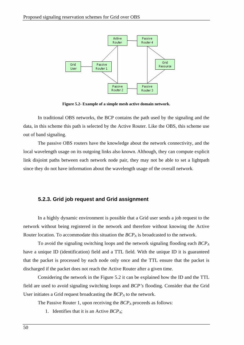
Proposed signaling reservation schemes for Grid over OBS
50
Figure 5.2- Example of a simple mesh active domain network.
In traditional OBS networks, the BCP contains the path used by the signaling and the
data, in this scheme this path is selected by the Active Router. Like the OBS, this scheme use
out of band signaling.
The passive OBS routers have the knowledge about the network connectivity, and the
local wavelength usage on its outgoing links also known. Although, they can compute explicit
link disjoint paths between each network node pair, they may not be able to set a lightpath
since they do not have information about the wavelength usage of the overall network.
5.2.3. Grid job request and Grid assignment
In a highly dynamic environment is possible that a Grid user sends a job request to the
network without being registered in the network and therefore without knowing the Active
Router location. To accommodate this situation the BCPA is broadcasted to the network.
To avoid the signaling switching loops and the network signaling flooding each BCPA
have a unique ID (identification) field and a TTL field. With the unique ID it is guaranteed
that the packet is processed by each node only once and the TTL ensure that the packet is
discharged if the packet does not reach the Active Router after a given time.
Considering the network in the Figure 5.2 it can be explained how the ID and the TTL
field are used to avoid signaling switching loops and BCP’s flooding. Consider that the Grid
User initiates a Grid request broadcasting the BCPA to the network.
The Passive Router 1, upon receiving the BCPA proceeds as follows:
1. Identifies that it is an Active BCPA;

Proposed signaling reservation schemes for Grid over OBS
51
2. Verify if it is the first time that this BCPA passes through it;
3. Verify the TTL field;
4. If the steps 2 and 3 are valid then broadcast the BCPA to the network.
The proposed scheme differs from the one proposed by [2][50] in two ways. First the
job specifications are transmitted inside the Active BCP frame, while in [2][50] the job
specifications are transmitted in the data burst transmitted after a JET offset time. The second
difference is that in the proposed scheme the Active Router manage the Grid resources as well
as the network resources, while in [2][50] the Active Router only perform as a Grid Resource
finder.
If a Grid resource that satisfy the client requirements is found, and there is network
transmission resources (wavelengths channels) availability to the Grid User reach the Grid
Resource, the Active Router sends an ACK packet to the source node using the shortest path.
5.2.4. Signaling flow
This section presents the signaling messages flow in the WR-OBS proposed scheme
and the most common signaling strategy used in OBS networks, JET-OBS. The JET-OBS
presented is an adaption of the usual JET (see section 2.8.1) to work in a Grid over OBS
network controlled by an Active Router.
Proposed WR-OBS strategy
Considering the network topology in Figure 5.2 and the Figure 5.3 which presents the
time scale of a job request from the Grid User to the Grid resource, the path selected by the
Active Router to satisfy this job is Grid User→ Passive Router 1 → Active Router → Passive
Router 4 → Grid resource.
The reservation process starts with the Grid User broadcasting to the network the BCP
packet until it reach the Active Router. This packet is broadcasted by every node until it reach
is destiny. When the Active Router receives the BCP, it processes it, and with its information
(i.e. job requirements) selects the Grid Resource and the appropriate path to connect the Grid
User to the Grid Resource. After this the reservation process starts, the Active Router send to
the routers that participate in the transmission an OXC_config packet, with the necessary

Proposed signaling reservation schemes for Grid over OBS
52
information (wavelength, duration, offset, ingress port and egress port) in order to the routers
be able to forward the burst when it arrive. The Offset indicates the time that the node waits
since it receives the OXC_Config message until it starts the OXC reconfiguration. During the
Offset time (Toffset), if necessary, the OXC can be used by other lightpaths. Beside the
intervenient nodes configuration, the Grid User will also be configured using an ACK CP that
the Active Router sends to the Grid User. All the packets used for configuration are
transmitted by the Active Router using the shortest paths, in this way the reservation process is
performed as fastest as possible.
The reconfiguration process is performed only if exists enough resources. In this case
the Active Router send a negative ACK to the Grid User informing it about the unavailability
of resources to satisfy the job, in this scenario, the job is dropped by the Grid User.
The Figure 5.4 shows the JET-OBS schemes packets flow representation used by this
dissertation to compare with the WR-OBS performance. This scheme is a JET adaption to
operate in a GOBS network with Active Routers. In this scheme, the Active Router is only
responsibility to select the Job Resource used to satisfy the job. This feature is illustrated in
the beginning of the timescale presented by the Figure 5.4 with the Grid User sending a BCP
to the Active Router. When the Active Router receives the BCP packet it selects the Grid
Resource based in the job specification. The Active Router send an ACK CP to the Grid user
informing the Grid Resource location, if exists a Grid Resource able to satisfy the jobs.
Otherwise, the Active Router informs the resource unavailability to the source node using a
negative ACK. Once the information about the Grid Resource arrives to the Grid User, it
selects the best path to reach the Grid Resource and transmit the BCP along the path. The
BCP and Grid Job are transmitted along the same path. The Grid job is transmitted after
waiting the enough time to guarantee that the BCP already reserve the network resources
along the path.
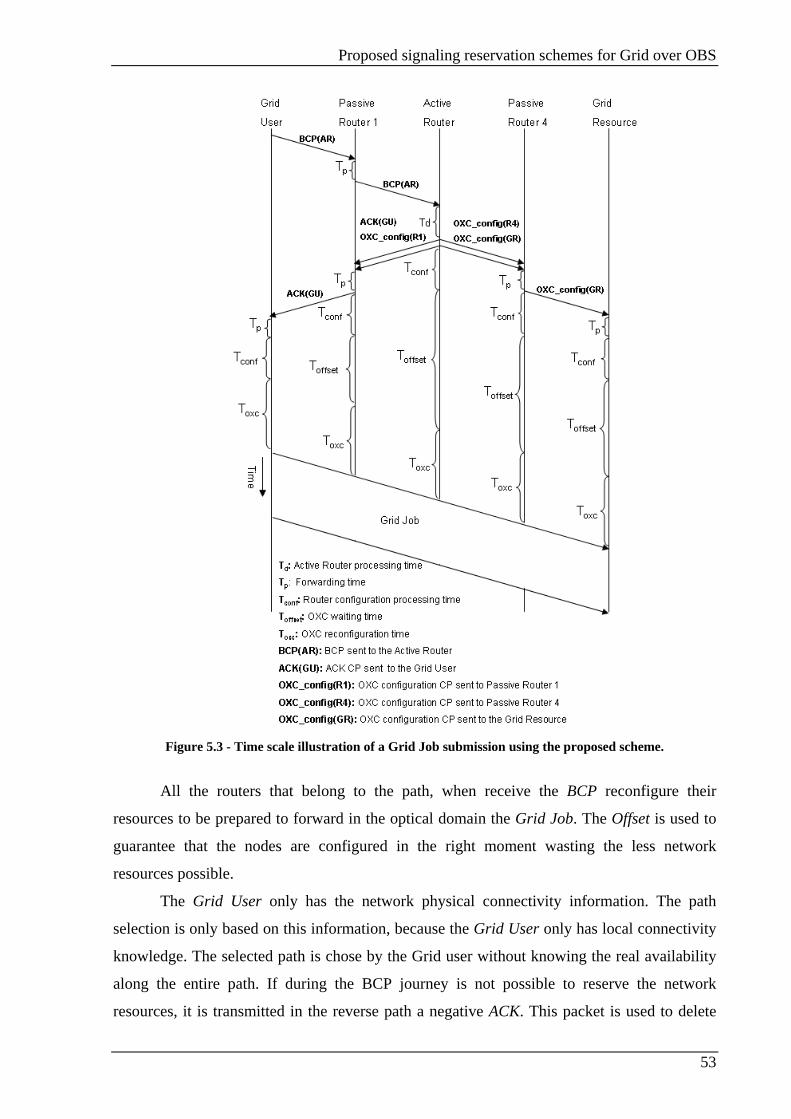
Proposed signaling reservation schemes for Grid over OBS
53
Figure 5.3 - Time scale illustration of a Grid Job submission using the proposed scheme.
All the routers that belong to the path, when receive the BCP reconfigure their
resources to be prepared to forward in the optical domain the Grid Job. The Offset is used to
guarantee that the nodes are configured in the right moment wasting the less network
resources possible.
The Grid User only has the network physical connectivity information. The path
selection is only based on this information, because the Grid User only has local connectivity
knowledge. The selected path is chose by the Grid user without knowing the real availability
along the entire path. If during the BCP journey is not possible to reserve the network
resources, it is transmitted in the reverse path a negative ACK. This packet is used to delete
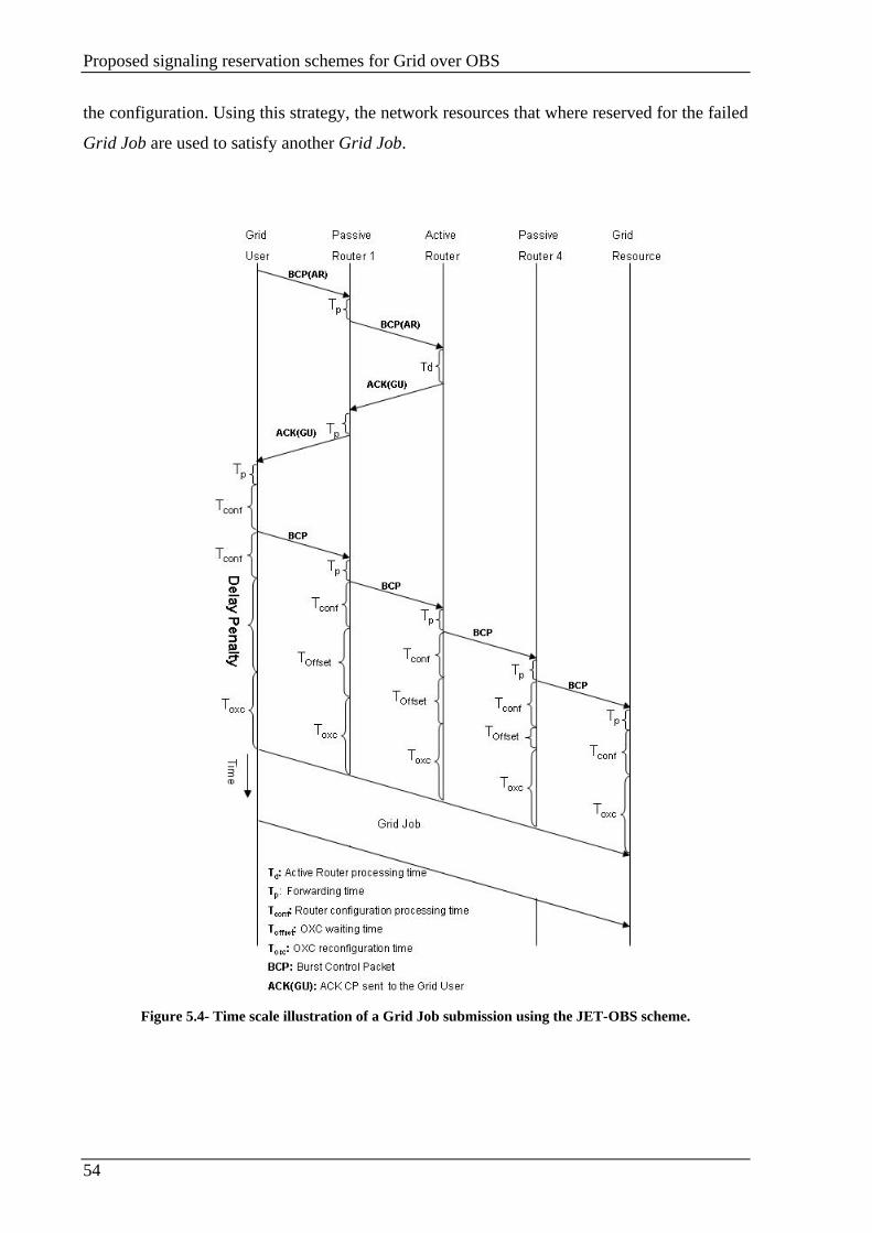
Proposed signaling reservation schemes for Grid over OBS
54
the configuration. Using this strategy, the network resources that where reserved for the failed
Grid Job are used to satisfy another Grid Job.
Figure 5.4- Time scale illustration of a Grid Job submission using the JET-OBS scheme.
Proposed signaling reservation schemes for Grid over OBS
55
5.2.5. Delays Introduced
In the time scale illustrations (Figure 5.3 and Figure 5.4), several delays are
represented. The total time is the time consumed with the propagation and processing of the
packets (Td, Tp, Tconf, Toffset and TOXC ).
Td is the time used by the Active Router to process the BCP packets. This function
corresponds to selecting the best Grid Resource for the Grid Job requirements. In our
signaling scheme it corresponds also to select the best path for the Grid Job.
Tp is the time used to forward the packets for the next node.
The time that the nodes use to process the BCP packet is represent by Tconf.
Corresponds to the time used to read the BCP information. The information read from the
BCP is used to the OXC physical reconfiguration, and the time used is presented by TOXC. The
physical reconfiguration consists in the physical preparation to forward the job always in the
optical domain.
Tofsset is the offset time. It represents the time delay since the router receives the
configuration packets until it starts the OXC reconfiguration process. It is used to guarantee
that all the network resources are reserved when the Grid Job arrives to the node. The offset
time is used also to waste the minimum network resources, since the resources can be used by
another Burst until the configuration process beginning.
In the JET-OBS can incur a Delay penalty as it can be seen comparing the Figure 5.3
that represents the proposed scheme and the JET-OBS scheme figured in the Figure 5.4. The
Delay penalty depends on the network connectivity, since a network with higher connectivity
have less delay penalty.
5.2.6. Proposed scheme advantages
The principal proposed scheme advantage is the burst lost probability reduction; this
will be shown in more detail in Chapter 6. This reduction is obtained because the path used by
the burst is selected by the Active Router based on the Active Region connectivity and the
respective wavelength occupation. The wavelength usage and the network connectivity permit
the Active Router select the best path from the Grid User Network Interface to the respective
Grid Resource Network Interface based on the job requirements.

Proposed signaling reservation schemes for Grid over OBS
56
Another advantage is that the Active Router responsible to reserve the network
resources. Since the Active have the information about the Burst duration, and the used path
and wavelength. The Active Router updates the network status immediately when the burst
transmission finishes. The reservation process performed by the Active Router consists in
sending the OXC_config packet to all the nodes used by the Data Burst to connect the Grid
user with the Grid Resource. With the information, the nodes will reconfigure themselves to
in the respective time slot be prepared for the burst. The configuration process made by the
Active Router permit a reduction in the offset times, because since this process isn’t started by
the GUNI like in the most common OBS strategies. In, the BCP ACK is transmitted to the
GUNI, at the same time that the OXC_config packets are transmitted to the other path nodes.
Using this strategy, the reconfiguration process can be anticipated, since the OXC_Config can
reach all the nodes sooner than when the configuration process is started by the Grid User. In
JET-OBS the reconfiguration starts when the Grid User receive the BCP ACK, while in our
scenario, this process is started by the Active Router, permitting anticipate the DB
transmission
5.3. Chapter summary
This chapter presents the signaling schemes implemented in this master dissertation.
The signaling scenarios implemented are a JET-OBS to our GOBS network controlled by an
Active Router and the novel WR-OBS signaling scheme proposed by this master dissertation.
In our JET-OBS, the Active Router is responsible to select the Grid resource and the
path to reach it is selected by the source node, while in the proposed scheme, the Active router
selects the Grid resource and the best path to reach it.
Implementation and performance assessment of the reservation signaling scheme
57
Chapter 6. Implementation and performance assessment of the reservation signaling scheme
6.1. Introduction
This chapter describes the implementation of the proposed reservation signaling
scheme presented in the previous chapter. OMNeT++ is the network simulator used for the
scheme implementation.
Using the simulation model the performance of Grid over Optical Burst Switching
(OBS) networks employing Active Routers is evaluated and compared with the JET-OBS
scheme. The results show that the centrally controlled WR-OBS signaling scheme always
outperforms the JET-OBS scheme in terms of job blocking rate and the time delay that a job
suffers until it reaches the Grid service provider.
6.2. OMNeT++ simulation model
OMNeT++ is a discrete event simulator, which primary application area is
communication networks. It is used for the simulation of several areas, such as: IT systems,
queuing networks, hardware architectures and business processes [57].
The simulation model was implemented in two levels: network and protocol. The
network level uses a specific OMNeT++ programming language, the ned language. The ned
language enables the definition of the nodes and the network physical structure. The links are
also defined using the ned language. The nodes functions are implemented in C++
programming language. OMNeT++ makes a perfect interaction between the network modules
and its functions implemented in C++.
Omnet.ini file have several simulation parameters declaration allowing the parameters
change without the necessity of recompiling the source code.
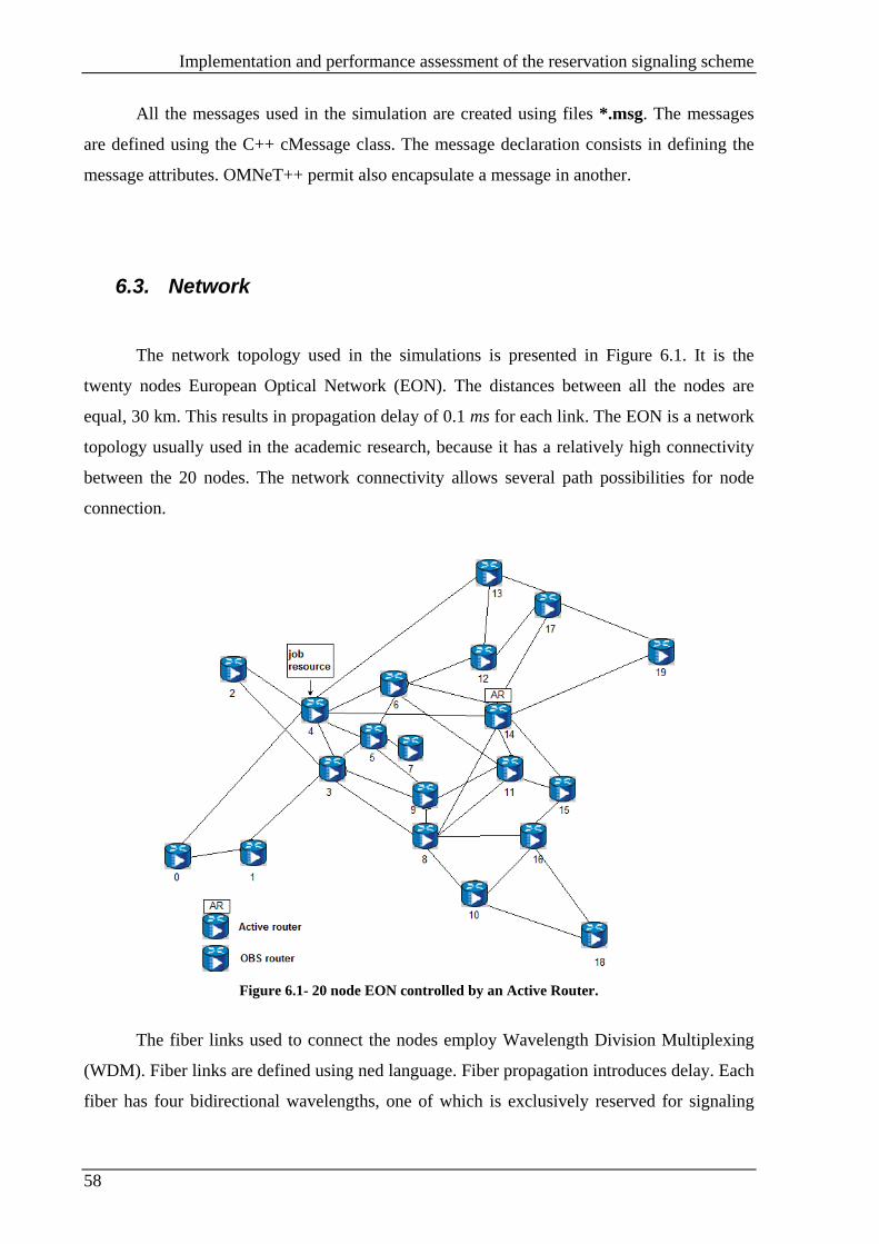
Implementation and performance assessment of the reservation signaling scheme
58
All the messages used in the simulation are created using files *.msg. The messages
are defined using the C++ cMessage class. The message declaration consists in defining the
message attributes. OMNeT++ permit also encapsulate a message in another.
6.3. Network
The network topology used in the simulations is presented in Figure 6.1. It is the
twenty nodes European Optical Network (EON). The distances between all the nodes are
equal, 30 km. This results in propagation delay of 0.1 ms for each link. The EON is a network
topology usually used in the academic research, because it has a relatively high connectivity
between the 20 nodes. The network connectivity allows several path possibilities for node
connection.
Figure 6.1- 20 node EON controlled by an Active Router.
The fiber links used to connect the nodes employ Wavelength Division Multiplexing
(WDM). Fiber links are defined using ned language. Fiber propagation introduces delay. Each
fiber has four bidirectional wavelengths, one of which is exclusively reserved for signaling

Implementation and performance assessment of the reservation signaling scheme
59
purposes, The wavelength reserved exclusively for the signaling allow the signaling to reach
the respective destiny even with all the data wavelengths reserved for the jobs transmission.
The networks have two different types of nodes, the OBS Router and the Active
Router. The OBS Router is simpler than the Active Router. The OBS Routers can be Job
Resources or Grid Clients. The Grid Client collects traffic from the attached network in the
form of jobs. For each job, a Control Packer is created and used to reserve the network
resources along the path. When it is performing as Job Resource it is capable to resolve the
jobs created by the Grid clients. The Active Router is a more complex entity; it has the same
function of the Grid client OBS Router, plus all the managing functions. The Active Router is
a network entity with a global knowledge of the network physical connectivity and status.
When the Active Router receives the Grid job specification, it uses the network information to
select the appropriate Job Resource and path to connect the source node to the Job Resource
using one of the shortest paths.
We consider the network represented in Figure 6.1 a single Active Region. The Active
Router controls the Active Region and maintains updated the network status. A single Grid
job resource is used to resolve the jobs requested by all the other nodes within the Active
Region.
6.3.1. OBS Router
The OBS Router can be a Grid Job Resource or Grid client. When acting as a Job
Resource its main function is resolve Grid Jobs. In our model only one OBS Router is the
Gird Job Resource able to resolve all the types of jobs. In a network with several Job
Resources they are able to interpret the Control Packets information and forward jobs to the
appropriate end node. We consider a Grid Job Resource with no capability to start job
resources requests.
The Grid client is responsible for job creation and to transmit to the Active Router a
Control Packet with the job specifications. The jobs are maintained in an electric buffer until
the Active Router receives an Ack message. If the Active Router informs that it is not possible
to find a path to satisfy the job request, the job will be dropped. Otherwise a positive
acknowledgement with a Grid Job Resource and the information necessary to the job
transmission is received. Every OBS Router that belongs to the selected path receives a
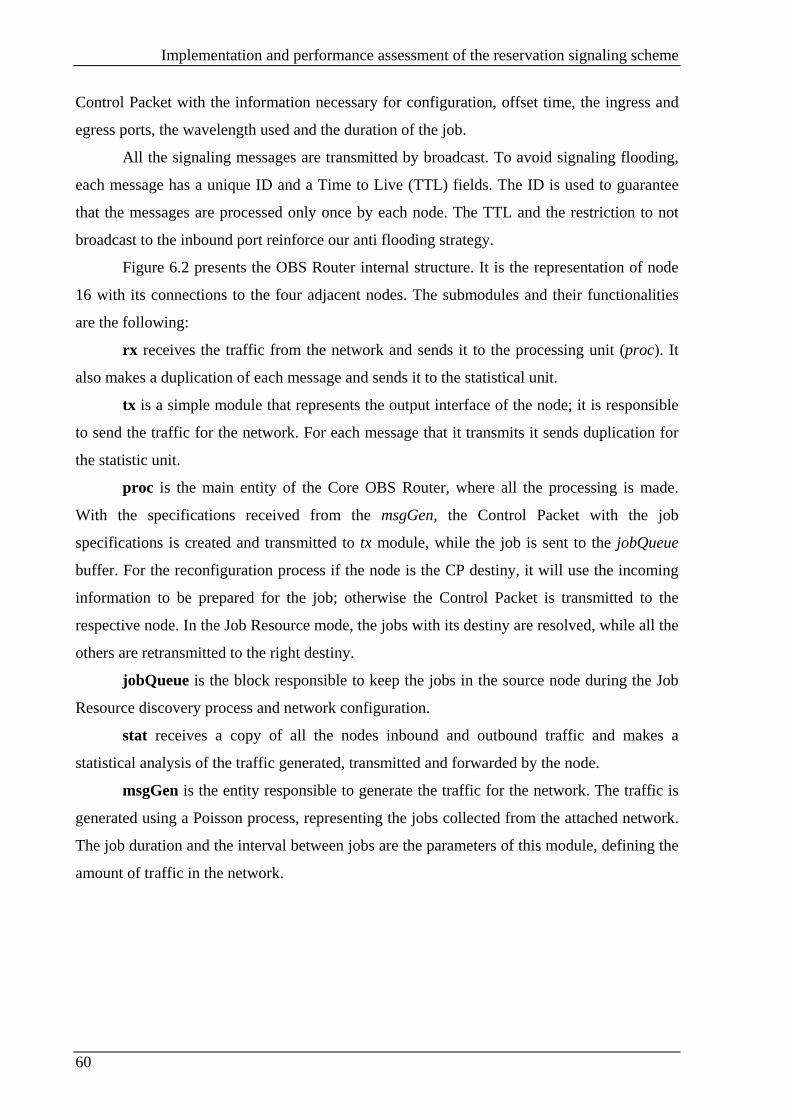
Implementation and performance assessment of the reservation signaling scheme
60
Control Packet with the information necessary for configuration, offset time, the ingress and
egress ports, the wavelength used and the duration of the job.
All the signaling messages are transmitted by broadcast. To avoid signaling flooding,
each message has a unique ID and a Time to Live (TTL) fields. The ID is used to guarantee
that the messages are processed only once by each node. The TTL and the restriction to not
broadcast to the inbound port reinforce our anti flooding strategy.
Figure 6.2 presents the OBS Router internal structure. It is the representation of node
16 with its connections to the four adjacent nodes. The submodules and their functionalities
are the following:
rx receives the traffic from the network and sends it to the processing unit (proc). It
also makes a duplication of each message and sends it to the statistical unit.
tx is a simple module that represents the output interface of the node; it is responsible
to send the traffic for the network. For each message that it transmits it sends duplication for
the statistic unit.
proc is the main entity of the Core OBS Router, where all the processing is made.
With the specifications received from the msgGen, the Control Packet with the job
specifications is created and transmitted to tx module, while the job is sent to the jobQueue
buffer. For the reconfiguration process if the node is the CP destiny, it will use the incoming
information to be prepared for the job; otherwise the Control Packet is transmitted to the
respective node. In the Job Resource mode, the jobs with its destiny are resolved, while all the
others are retransmitted to the right destiny.
jobQueue is the block responsible to keep the jobs in the source node during the Job
Resource discovery process and network configuration.
stat receives a copy of all the nodes inbound and outbound traffic and makes a
statistical analysis of the traffic generated, transmitted and forwarded by the node.
msgGen is the entity responsible to generate the traffic for the network. The traffic is
generated using a Poisson process, representing the jobs collected from the attached network.
The job duration and the interval between jobs are the parameters of this module, defining the
amount of traffic in the network.

Implementation and performance assessment of the reservation signaling scheme
61
Figure 6.2- OBS Router internal submodules.
6.3.2. Active Router
The Active Router is responsible to manage the network and its resources. This node
has the same functionalities that the Core OBS Router, plus the ones necessary for the
network management. One extra submodule is added, the sigQueue, which is responsible to
buffer Jobs Resource Requests. The Job Resource Requests are buffered, because the Active
Router only process one Control Packet at the time. The main function of this node is the
network management, for this proposes it needs to have a global knowledge of the network
physical structure and status. The physical structure is discovered using the Dijkstra’s
algorithm in the simulation start-up. With this knowledge it will select only the shortest paths
to resolve the jobs.
With the job characteristics, the Active Router selects the best Grid Job Resource to
resolve the job. When a signaling packet with the job characteristics arrives is queued. The
queuing process is necessary because the Active Router is only capable of resolving one job at
a time. After the queuing process, the best node to execute the job is selected based in the
knowledge of all the Grid Job Resources placed in the network. After selecting a Job
Resource, one of the free shortest paths is chosen. Wavelength continuity is assumed. When is
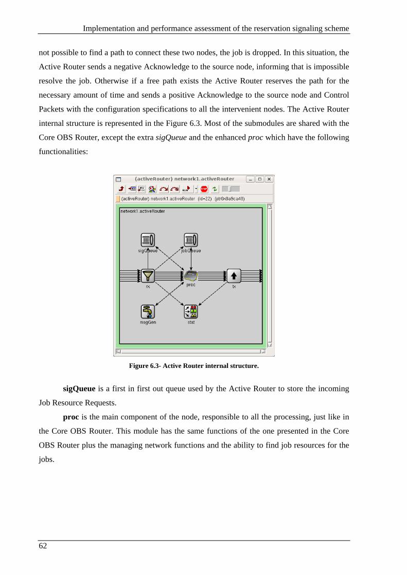
Implementation and performance assessment of the reservation signaling scheme
62
not possible to find a path to connect these two nodes, the job is dropped. In this situation, the
Active Router sends a negative Acknowledge to the source node, informing that is impossible
resolve the job. Otherwise if a free path exists the Active Router reserves the path for the
necessary amount of time and sends a positive Acknowledge to the source node and Control
Packets with the configuration specifications to all the intervenient nodes. The Active Router
internal structure is represented in the Figure 6.3. Most of the submodules are shared with the
Core OBS Router, except the extra sigQueue and the enhanced proc which have the following
functionalities:
Figure 6.3- Active Router internal structure.
sigQueue is a first in first out queue used by the Active Router to store the incoming
Job Resource Requests.
proc is the main component of the node, responsible to all the processing, just like in
the Core OBS Router. This module has the same functions of the one presented in the Core
OBS Router plus the managing network functions and the ability to find job resources for the
jobs.
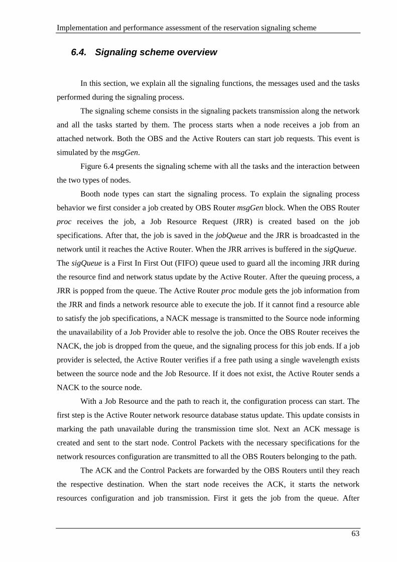
Implementation and performance assessment of the reservation signaling scheme
63
6.4. Signaling scheme overview
In this section, we explain all the signaling functions, the messages used and the tasks
performed during the signaling process.
The signaling scheme consists in the signaling packets transmission along the network
and all the tasks started by them. The process starts when a node receives a job from an
attached network. Both the OBS and the Active Routers can start job requests. This event is
simulated by the msgGen.
Figure 6.4 presents the signaling scheme with all the tasks and the interaction between
the two types of nodes.
Booth node types can start the signaling process. To explain the signaling process
behavior we first consider a job created by OBS Router msgGen block. When the OBS Router
proc receives the job, a Job Resource Request (JRR) is created based on the job
specifications. After that, the job is saved in the jobQueue and the JRR is broadcasted in the
network until it reaches the Active Router. When the JRR arrives is buffered in the sigQueue.
The sigQueue is a First In First Out (FIFO) queue used to guard all the incoming JRR during
the resource find and network status update by the Active Router. After the queuing process, a
JRR is popped from the queue. The Active Router proc module gets the job information from
the JRR and finds a network resource able to execute the job. If it cannot find a resource able
to satisfy the job specifications, a NACK message is transmitted to the Source node informing
the unavailability of a Job Provider able to resolve the job. Once the OBS Router receives the
NACK, the job is dropped from the queue, and the signaling process for this job ends. If a job
provider is selected, the Active Router verifies if a free path using a single wavelength exists
between the source node and the Job Resource. If it does not exist, the Active Router sends a
NACK to the source node.
With a Job Resource and the path to reach it, the configuration process can start. The
first step is the Active Router network resource database status update. This update consists in
marking the path unavailable during the transmission time slot. Next an ACK message is
created and sent to the start node. Control Packets with the necessary specifications for the
network resources configuration are transmitted to all the OBS Routers belonging to the path.
The ACK and the Control Packets are forwarded by the OBS Routers until they reach
the respective destination. When the start node receives the ACK, it starts the network
resources configuration and job transmission. First it gets the job from the queue. After

Implementation and performance assessment of the reservation signaling scheme
64
waiting the offset time, it starts the resources configuration. The next step is the job
transmission. With this, another part of the signaling scheme ends, now the source node is
prepared for the job transmission without the exchange of another signaling packet.
When an OBS Router receives a configuration Control Packet with his destination
means it is just a passing router. Then it will get the specifications from the Control Packet,
wait the appropriate offset time and configure the network resources with the specifications
carried in the signaling packet. With this, another signaling process ends, now the node is
prepared to forward the data carried in the job.
The Active Router, after sending the Control Packets and the ACK messages verifies
if it is the job sender. If so, it starts preparing for the job transmission, gets the job from the
jobQueue and uses the job specifications to configure its resources just after waiting the
respective offset time. Now the Active Router is prepared for the job transmission.
If the Active Router is not the source node, but belongs to the selected path, it prepares
for forwarding the job after waiting the offset time reserve the specific network resources.
Next, verifies if the jobQueue is empty. If it is, the signaling process finish there, otherwise,
the signaling process is repeated since a JRR is popped from the sigQueue.
If the Active Router is the source node, the signaling beginning is equal to the one
performed when the start node is an OBS Router. It starts with the JRR creation, following by
the job transmission to the jobQueue. At this point, the JRR is buffered in the sigQueue, while
when the OBS Router is the source node it is transmitted to the Active Router. After this the
signaling follows the normal flow, explained above in this section, and presented in the Figure
6.4.
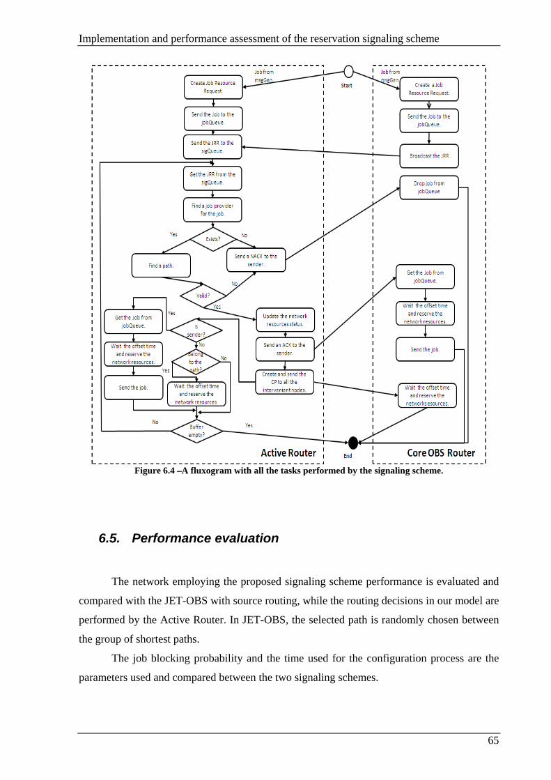
Implementation and performance assessment of the reservation signaling scheme
65
Figure 6.4 –A fluxogram with all the tasks performed by the signaling scheme.
6.5. Performance evaluation
The network employing the proposed signaling scheme performance is evaluated and
compared with the JET-OBS with source routing, while the routing decisions in our model are
performed by the Active Router. In JET-OBS, the selected path is randomly chosen between
the group of shortest paths.
The job blocking probability and the time used for the configuration process are the
parameters used and compared between the two signaling schemes.

Implementation and performance assessment of the reservation signaling scheme
66
The job requests are generated as a Poisson process with mean arrival rate λ
arrivals/ms. Job sizes are distributed according to a exponential distribution with mean 1/μ.
6.5.1. Blocking probability
We consider two different network scenarios: in the first scenario is considered an
Active Router with no sigQueue, while in the second strategy the sigQueue have queuing time
equal to the time used by the Active Router to select the job resource for a job (Td).
Figure 6.5 and Figure 6.6 represent blocking probability for the first scenario. When
the Job Resource Requests arrive to the Active Router, are resolved immediately. If the
Active Router receives more than one Job Resource Request at the same simulation time, all
the requests are resolved at the same simulation time in the entrance order. For example if the
Active Router receive two Resource Requests ate the same simulation time, the second
request is performed after the resource select and update of the first request. The second Job
Resource Request resource selection is based on the Active Router information after the first
requests update.
Figure 6.5 and Figure 6.6 are the blocking probability of two different Active Router
and job resource configuration. In Figure 6.5 is represented the Active Router in the node 17
and the job resource in node 18, while in Figure 6.6 the Active Router is the node 14 and the
job resource is node 4.
In Figure 6.5, plot, the Active Router and job resource are both edge nodes with the
less connectivity in the network, two adjacent nodes, the Active Router is placed in node 17
and the Grid Resource is the node 18. In Figure 6.6 both Active Router and job resource are
placed in a central location in the network (nodes 14 and 4). Both nodes have the higher
connectivity in the network, seven adjacent nodes.
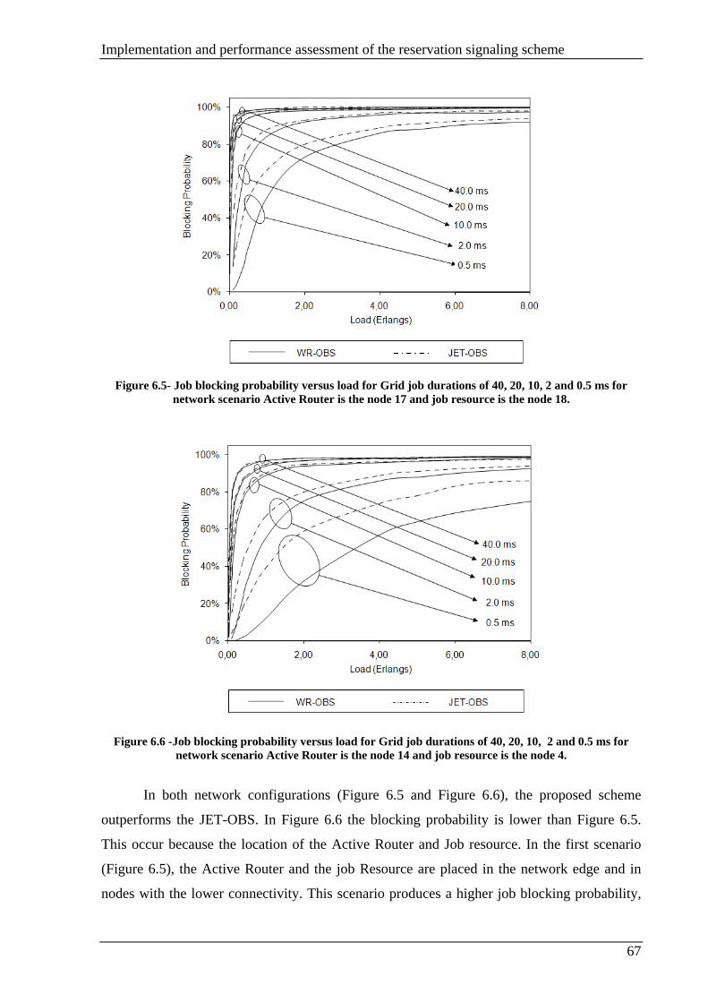
Implementation and performance assessment of the reservation signaling scheme
67
Figure 6.5- Job blocking probability versus load for Grid job durations of 40, 20, 10, 2 and 0.5 ms for
network scenario Active Router is the node 17 and job resource is the node 18.
Figure 6.6 -Job blocking probability versus load for Grid job durations of 40, 20, 10, 2 and 0.5 ms for
network scenario Active Router is the node 14 and job resource is the node 4.
In both network configurations (Figure 6.5 and Figure 6.6), the proposed scheme
outperforms the JET-OBS. In Figure 6.6 the blocking probability is lower than Figure 6.5.
This occur because the location of the Active Router and Job resource. In the first scenario
(Figure 6.5), the Active Router and the job Resource are placed in the network edge and in
nodes with the lower connectivity. This scenario produces a higher job blocking probability,
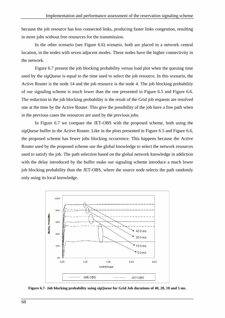
Implementation and performance assessment of the reservation signaling scheme
68
because the job resource has less connected links, producing faster links congestion, resulting
in more jobs without free resources for the transmission.
In the other scenario (see Figure 6.6) scenario, both are placed in a network central
location, in the nodes with seven adjacent modes. These nodes have the higher connectivity in
the network.
Figure 6.7 present the job blocking probability versus load plot when the queuing time
used by the sigQueue is equal to the time used to select the job resource. In this scenario, the
Active Router is the node 14 and the job resource is the node 4. The job blocking probability
of our signaling scheme is much lower than the one presented in Figure 6.5 and Figure 6.6.
The reduction in the job blocking probability is the result of the Grid job requests are resolved
one at the time by the Active Router. This give the possibility of the job have a free path when
in the previous cases the resources are used by the previous jobs.
In Figure 6.7 we compare the JET-OBS with the proposed scheme, both using the
sigQueue buffer in the Active Router. Like in the plots presented in Figure 6.5 and Figure 6.6,
the proposed scheme has fewer jobs blocking occurrence. This happens because the Active
Router used by the proposed scheme use the global knowledge to select the network resources
used to satisfy the job. The path selection based on the global network knowledge in addiction
with the delay introduced by the buffer make our signaling scheme introduce a much lower
job blocking probability than the JET-OBS, where the source node selects the path randomly
only using its local knowledge.
Figure 6.7- Job blocking probability using sigQueue for Grid Job durations of 40, 20, 10 and 5 ms.

Implementation and performance assessment of the reservation signaling scheme
69
The proposed scheme have always less blocking probability than the JET-OBS. The
gain increase when the job duration decreases. This proves that our model is very suitable for
Grid consumer scenarios, where the job durations are small.
6.5.2. Reservation time
One of the OBS features is a fast reservation process, the bursts should be retained in
the source node the minimum possible time, maximizing the network resources usage.
In this master dissertation we study four reservation time scenarios in a Grid over OBS
network. The reservation time considered is the time used since the burst creation until it
transmission after the respective offset time and reconfiguration process. The four scenarios
tested are the proposed scheme and JET-OBS in a buffer and buffers less network. The buffer
used is in the Active Router for the BCP Job Resource Packets. It is considered a buffer with
infinite capacity. Using the infinite buffer, the jobs only are dropped because the network
resources for the job transmission are not available.
The network delays are those represented in the Table 6.1. These delays represent the
propagation delay and all the times used by the nodes for processing and configuration during
the network configuration.
Time (ms) Propagation delay 0.1 Configuration Processing Time (Tconf) 0.08 Configuration Time (Toxc) 1 Active Router Function Time (Td) 0.2 Signaling delay (Tp) 0.01
Table 6.1 – Delays introduced by the network during the simulation.
In Table 6.2 and Table 6.3- are presented the first two scenarios, using a bufferless
Active Router. It was tested two network configurations, in Table 6.2 the Active Router is
placed in the node 17 and the Job Provider is the node 18, these two nodes are placed in the
network edge and both have low connectivity. The network configuration used for the results
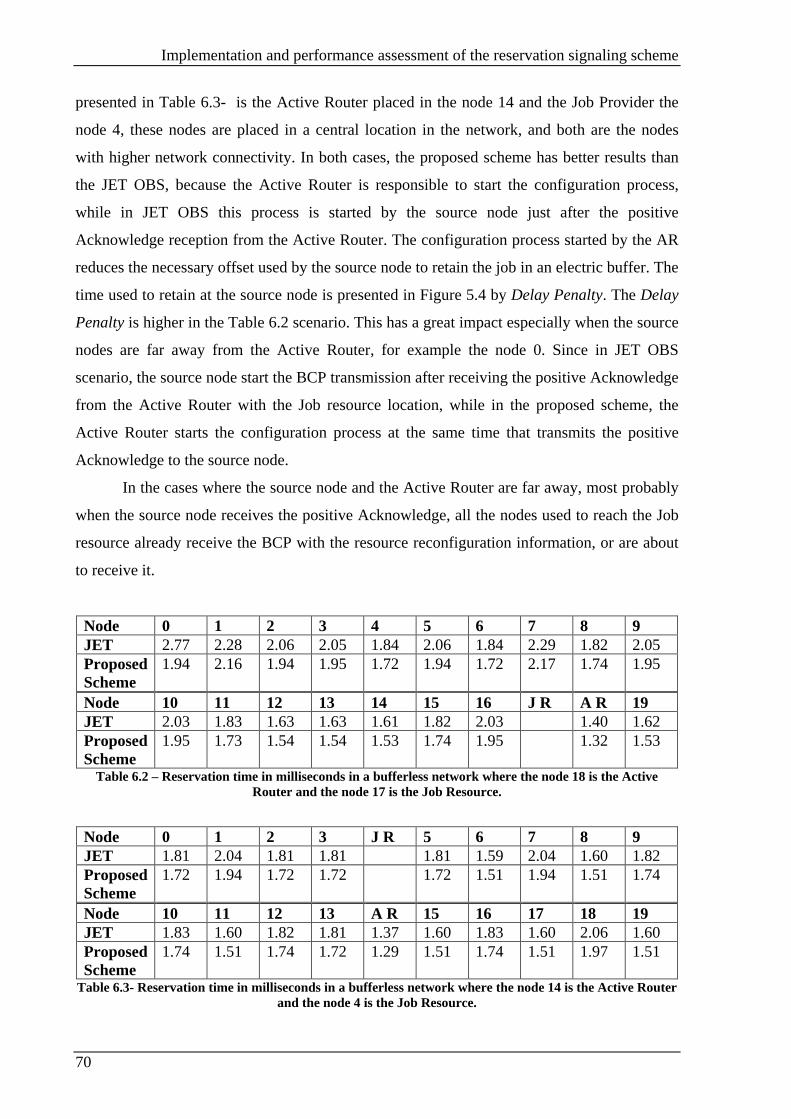
Implementation and performance assessment of the reservation signaling scheme
70
presented in Table 6.3- is the Active Router placed in the node 14 and the Job Provider the
node 4, these nodes are placed in a central location in the network, and both are the nodes
with higher network connectivity. In both cases, the proposed scheme has better results than
the JET OBS, because the Active Router is responsible to start the configuration process,
while in JET OBS this process is started by the source node just after the positive
Acknowledge reception from the Active Router. The configuration process started by the AR
reduces the necessary offset used by the source node to retain the job in an electric buffer. The
time used to retain at the source node is presented in Figure 5.4 by Delay Penalty. The Delay
Penalty is higher in the Table 6.2 scenario. This has a great impact especially when the source
nodes are far away from the Active Router, for example the node 0. Since in JET OBS
scenario, the source node start the BCP transmission after receiving the positive Acknowledge
from the Active Router with the Job resource location, while in the proposed scheme, the
Active Router starts the configuration process at the same time that transmits the positive
Acknowledge to the source node.
In the cases where the source node and the Active Router are far away, most probably
when the source node receives the positive Acknowledge, all the nodes used to reach the Job
resource already receive the BCP with the resource reconfiguration information, or are about
to receive it.
Node 0 1 2 3 4 5 6 7 8 9 JET 2.77 2.28 2.06 2.05 1.84 2.06 1.84 2.29 1.82 2.05 Proposed Scheme
1.94 2.16 1.94 1.95 1.72 1.94 1.72 2.17 1.74 1.95
Node 10 11 12 13 14 15 16 J R A R 19 JET 2.03 1.83 1.63 1.63 1.61 1.82 2.03 1.40 1.62 Proposed Scheme
1.95 1.73 1.54 1.54 1.53 1.74 1.95 1.32 1.53
Table 6.2 – Reservation time in milliseconds in a bufferless network where the node 18 is the Active Router and the node 17 is the Job Resource.
Node 0 1 2 3 J R 5 6 7 8 9 JET 1.81 2.04 1.81 1.81 1.81 1.59 2.04 1.60 1.82 Proposed Scheme
1.72 1.94 1.72 1.72 1.72 1.51 1.94 1.51 1.74
Node 10 11 12 13 A R 15 16 17 18 19 JET 1.83 1.60 1.82 1.81 1.37 1.60 1.83 1.60 2.06 1.60 Proposed Scheme
1.74 1.51 1.74 1.72 1.29 1.51 1.74 1.51 1.97 1.51
Table 6.3- Reservation time in milliseconds in a bufferless network where the node 14 is the Active Router and the node 4 is the Job Resource.

Implementation and performance assessment of the reservation signaling scheme
71
As was shown in the section 6.5.1 the burst dropping probability in the scenarios
employing buffers is much lower than the scenarios without buffers. The buffered scenarios
introduce delay; it is interesting study the delay introduced by the buffers, because this delay
corresponds to the time that is necessary retain the jobs in the source node by an electrical
data buffer.
To study the delay introduced by the buffer we select a job average duration and vary
the interval between the job resource requests. The job duration only interferes with the
blocking probability, since larger jobs use the resources during more time, increasing the
blocking. The sigQueue buffer is an infinite buffer, where all the job requests are processed
by the Active Router. The following job resource request is only processed when the current
is already served (select the Grid Resource, select the path from the source node to the Grid
Resource, update the network status, transmit the Acknowledge for the source node and the
BCP’s to all the other intervenient nodes). All the jobs have the same processing time, Td (0.2
ms).
The reservation time of the network with buffer is tested in the network presented in
Figure 6.1. The Table 6.4, Table 6.5, Table 6.6 and Table 6.7 present the reservation time for
four different average Job Resource Request generation times and a fixed average job
duration. It is studied for each node, the average, maximum and minimum reservation times.
It is presented the average time, as well as the time wasted for the first job, and the maximum
delay introduced by the buffer for each source node.
Table 6.4 presents the reservation time used for an average generation interval of 10
ms. Since the burst generation rate is low, the buffer has low usage. The average reservation
times are very similar to the minimum. The minimum reservation time presented in Table 6.4
are equal to the one performed by a bufferless network (see Table 6.3- ). In the scenario
presented in Table 6.5, where the average interval is 5 ms, the buffer has more influence in
the reservation times. The minimum reservation time is equal to the one performed by the
bufferless scenario, while the average time are slightly higher.

Implementation and performance assessment of the reservation signaling scheme
72
Node 0 1 2 3 J R 5 6 7 8 9 JET Average 1.88 2.10 1.87 1.88 1.88 1.65 2.10 1.68 1.89
Max 2.64 2.74 2.70 2.55 2.47 2.30 2.72 2.50 2.84 Min 1.81 2.04 1.81 1.81 1.81 1.59 2.04 1.60 1.82
Proposed Scheme
Average 1.77 2.05 1.78 1.77 1.78 1.58 1.99 1.57 1.79 Min 2.57 2.46 2.41 2.34 2.41 2.18 2.60 2.14 2.30 Max 1.72 1.94 1.72 1.72 1.72 1.51 1.94 1.51 1.94
Node 10 11 12 13 A R 15 16 17 18 19 JET Average 1.89 1.66 1.88 1.87 1.42 1.66 1.89 1.67 2.11 1.66
Max 2.50 2.27 2.67 2.62 1.95 2.31 2.65 2.47 2.83 2.22 Min 1.83 1.60 1.82 1.81 1.37 1.60 1.83 1.60 2.06 1.60
Proposed Scheme
Average 1.78 1.58 1.80 1.77 1.34 1.57 1.79 1.56 2.02 1.57 Max 2.42 2.54 2.43 2.46 2.15 2.37 2.57 2.14 2.49 2.25 Min 1.74 1.51 1.74 1.72 1.29 1.51 1.74 1.51 1.97 1.51
Table 6.4- Average, Maximum and minimum reservation time in a buffered network where the node 14 is the Active Router and the node 4 is the job resource, with 5ms of average message duration and 10 ms of
average time between the generation of the job requests.
Node 0 1 2 3 J R 5 6 7 8 9 JET Average 2.11 2.34 2.12 2.11 2.08 1.87 2.34 1.87 2.13
Max 5.17 4.82 4.56 4.39 3.69 3.60 5.16 3.33 458 Min 1.81 2.04 1.81 1.81 1.81 1.59 2.04 1.60 1.82
Proposed Scheme
Average 1.98 2.23 2.01 2.02 1.96 1.78 2.17 1.79 2.00 Min 3.78 3.70 3.38 3.84 3.63 3.32 3.58 3.50 3.64 Max 1.72 1.94 1.72 1.72 1.72 1.51 1.94 1.51 1.74
Node 10 11 12 13 A R 15 16 17 18 19 JET Average 2.14 1.87 2.14 2.11 1.66 1.91 2.12 1.88 2.33 1.91
Max 4.36 3.61 5.13 4.29 4.35 4.59 4.39 3.50 4.36 4.86 Min 1.83 1.60 1.82 1.81 1.37 1.60 1.83 1.60 2.06 1.60
Proposed Scheme
Average 2.02 1.77 2.03 2.00 1.54 1.78 2.02 1.79 2.23 1.78 Max 3.71 3.77 3.82 3.74 3.01 3.54 3.71 3.46 3.68 3.33 Min 1.74 1.51 1.74 1.72 1.29 1.51 1.74 1.51 1.97 1.51
Table 6.5- Average, Maximum and minimum reservation time in a buffered network where the node 14 is the Active Router and the node 4 is the job resource, with 5ms of average message duration and 5ms of
average time between the generation of the job requests.
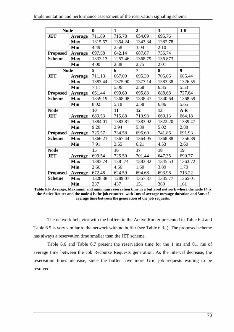
Implementation and performance assessment of the reservation signaling scheme
73
Node 0 1 2 3 J R JET Average 711.89 715.78 654.09 695.76
Max 1315.57 1354.24 1343.34 1382.78 Min 4.49 2.58 3.04 2.10
Proposed Scheme
Average 697.58 642.14 687.87 735.74 Max 1333.13 1257.46 1368.79 136.873 Min 4.00 2.38 2.75 2.01
Node 5 6 7 8 9 JET Average 711.13 667.00 695.39 706.66 685.44
Max 1383.44 1375.90 1377.14 1383.38 1326.55 Min 7.11 5.06 2.68 6.35 5.53
Proposed Scheme
Average 661.44 699.60 695.83 688.68 727.84 Max 1359.19 1368.08 1338.47 1340.64 1368.59 Min 8.02 5.18 2.58 6.86 5.65
Node 10 11 12 13 A R JET Average 689.53 715.88 719.93 660.13 664.18
Max 1384.01 1383.81 1383.92 1322.20 1339.47 Min 9.20 3.94 5.89 5.02 2.88
Proposed Scheme
Average 725.57 734.58 696.69 741.86 691.93 Max 1366.21 1367.44 1364.05 1368.88 1356.89 Min 7.91 3.65 6.21 4.53 2.60
Node 15 16 17 18 19 JET Average 699.54 725.50 701.44 647.35 690.77
Max 1383.74 138’.74 1383.82 1345.53 1363.72 Min 2.66 4.66 1.60 3.89 1.70
Proposed Scheme
Average 672.48 624.59 694.68 693.98 713.22 Max 1328.38 1289.07 1357.37 1335.77 1365.01 Min 237 437 151 360 161
Table 6.6- Average, Maximum and minimum reservation time in a buffered network where the node 14 is the Active Router and the node 4 is the job resource, with 1ms of average message duration and 5ms of
average time between the generation of the job requests.
The network behavior with the buffers in the Active Router presented in Table 6.4 and
Table 6.5 is very similar to the network with no buffer (see Table 6.3- ). The proposed scheme
has always a reservation time smaller than the JET scheme.
Table 6.6 and Table 6.7 present the reservation time for the 1 ms and 0.1 ms of
average time between the Job Recourse Requests generation. As the interval decrease, the
reservation times increase, since the buffer have more Grid job requests waiting to be
resolved.

Implementation and performance assessment of the reservation signaling scheme
74
Node 0 1 2 3 J R JET Average 907.54 927.93 930.99 933.78
Max 1828.47 1829.84 1820.45 1792.83 Min 4.99 6.79 3.84
Proposed Scheme
Average 986.97 938.83 948.35 891.89 Max 1844.98 1836.31 1838.85 1827.13 Min 4.70 6.69 4.35 3.98
Node 5 6 7 8 9 JET Average 805.54 912.93 900.26 953.31 932.06
Max 1655.66 1838.00 1749.39 1845.46 1839.69 Min 9.47 3.05 6.99 5.38 7.94
Proposed Scheme
Average 923.03 973.82 957.04 977.15 907.75 Max 1794.50 1845.51 1800.32 1835.71 1768.16 Min 15.24 3.97 6.89 4.89 7.66
Node 10 11 12 13 A R JET Average 929.76 897.90 884.32 980.55 965.45
Max 1768.66 1789.18 1782.54 1844.83 1829.95 Min 10.46 2.48 8.12 5.78 1.37
Proposed Scheme
Average 895.86 853.45 919.61 935.78 832.93 Max 1802.23 1756.57 1819.67 1836.46 1738.46 Min 10.77 3.39 8.64 5.69 1.29
Node 15 16 17 18 19 JET Average 953.92 941.57 877.76 923.85 906.15
Max 1829.98 1837.87 1757.44 1835.68 1827.66 Min 2.33 6.00 1.71 8.75 1.96
Proposed Scheme
Average 940.39 873.11 960.37 973.44 885.59 Max 1811.59 1809.10 1828.82 1844.90 1799.13 Min 2.44 5.91 1.88 9.06 2.27
Table 6.7- Average, Maximum and minimum reservation time in a buffered network where the node 14 is the Active Router and the node 4 is the job resource, with 0.1ms of average message duration and 5ms of
average time between the generation of the job requests.
Until now, it was compared the performance between the JET-OBS and the proposed
scheme always under the same network parameters. The relation between both remains almost
identical in the networks with and without buffer in the Active Router; this is particularly
noticeable when Table 6.3- , Table 6.4 and Table 6.5 are compared.
6.6. Chapter summary
In this chapter we present the proposed scheme OMNeT++ implementation and
evaluate its performance in terms the job blocking probability and reservation time.

Implementation and performance assessment of the reservation signaling scheme
75
The performance of the proposed scheme was compared with the JET-OBS with
random source routing.
The proposed scheme job blocking probability always outperforms the JET-OBS
under the same circumstances, because the path selection is made by the Active Routing using
the network global knowledge.
In a bufferless Active Router network, the proposed scheme has a reservation time
shorter than JET-OBS networks. Using networks where the Active Router have the sigQueue
buffer for the Grid job resource requests, the proposed scheme reservation time is lower than
the one used by JET OBS when the jobs are generated with a low frequency, while when the
generation frequency increases the buffer introduces a larger delay in both cases.

Path selection strategies
77
Chapter 7. Path selection strategies
7.1. Introduction
In this chapter a novel path selection strategy based on a probabilistic model for the
link demands is presented. The objective of this strategy is to minimize the burst dropping
probability. In the proposed scheme, during the network startup, the shortest paths are sorted
based on a probabilistic model. This scheme avoids all the signaling packets exchange to
update the actual network status used by adaptive path selection strategies.
The reminder of this chapter is organized as the follows. First an overview of several
path selection strategies is presented; next the path selection strategy based on the
probabilistic model is presented and explained. The chapter concludes with the path selection
strategy performance evaluation.
7.2. Static contention avoidance strategies
There are several contention avoidance techniques that use load balancing techniques
to avoid contention. The contention avoidance techniques based on load balancing can be
static or dynamic. In static, the paths are selected using static metrics, such as hop counting or
physical distance. In the dynamic strategy, the paths are selected using the number of
congestions or the place of the congestions in the network as parameters [58].
7.3. Adaptive path selection strategies
The adaptative strategies objective is minimize the OBS burst dropping probability
using the actual network status. The adaptative routing avoids the burst dropping using
contention avoidance techniques.
Path selection strategies
78
In adaptative routing, the actual network status is updated. The network status is
propagated along the network using link state signaling protocols witch use Link State
Advertisement (LSA) messages to propagate the updated network status along the network.
The path selection is based on the actual network status. In traditional networks, protocols like
RIP [59][60], OSPF [61], IS-IS [62] and IGRP/EIGRP [63][64] used to archive networks with
adaptive routing.
Adaptative path selection strategies can be classified as pure or hybrid.
7.3.1. Pure path selecting strategies
In pure path selection strategies, the source node maintains a small list of paths used to
route the bursts from the source to the end node. There are several parameters used to measure
the network congestion, for example: link usage and end to end path drop rate. With that
information, the paths are ranked using different strategies to avoid the maximum burst drop.
In [65] are presented three pure path selecting strategies. The Weighted Bottleneck Link
Utilization (WBLU), the Weighted Link Congestion (WLC) and End-to-End Path Priority-
Based (EPP) strategies.
In WBLU, the links utilization is the metric used to rank the paths. The author
intention is to select the paths less used to reduce or prevent the contention in the network. In
WBLU, the selected path is the one with the higher ratio of available bottleneck link capacity
to path length. If the bottleneck ratio is similar between two paths, the shortest path is
selected. The longer path is preferred only when the utilization of it bottleneck link is much
lower than the shorter one.
In WLC, the burst is routed in the path that most likely leads to a successful
transmission. The source node decision is made based on the link congestion along each path
to infer the path burst drop rate. This strategy needs a link state protocol to propagate the links
usage along the network. Like in the previous strategy, the longer paths are preferred over
shorter only if offer a substantial improvement in drop probability.
The EPP is similar to WLC, the busts are routed in the paths with less dropping
probability. In this case instead of measuring the individual link congestion to infer the
dropping probability, the dropping probability is measured in the all path based on the burst
transmission feedback.
Path selection strategies
79
7.3.2. Hybrid path selecting strategies
The problem present in pure path selection strategies is that each strategy only uses a
partial part of the network state to select the path. In the hybrid strategies, for each burst
transmission combines the decision of several pure strategies into an overall decision.
Combining several pure strategies, the overall burst drop probability can be minimized.
In [65] three hybrid path selection strategies are presented. The Majority Binary
Voting (MBV), Weighted Nonbinary Voting (WNV) and the Dynamic WNV (DWNV)
strategies.
In MBV are considered a group of pure path selection strategies. For each strategy is
verified if it is used to select the path. The strategy selected by the MBV is the one which is
used to resolve most paths.
In WNV like in MBV are considered a group of pure path selection strategies. For
each selection strategy is assigned a degree of confidence to each candidate path through a
probability distribution. The WNV sort the strategies for each path, based on the degree of
confidence. The performance of the various pure strategies depends on systems parameters,
such as the network topology, traffic load and pattern. Each pure strategy has a different error
rate, this hybrid strategy sort them by the respective weight.
The drawback in WNV is that the pure path selection strategy selected remains fixed
all the time. The DWNV select which pure path strategy used, based on the burst dropping
probability. The feedback information about the previous bursts transmitted along the path is
used to calculi the path dropping probability.
7.4. Path selection strategy based on a probabilistic model for the link demands
In this section is presented the proposed path selection strategy based on a
probabilistic model. The proposed scheme is a non adaptative strategy, where the paths are
selected based on the network connections and the possible demands between all source-
destinations combinations.
The probabilistic model for the link demands predicts a possible network load based
on a probabilistic model. The paths usage discovery is made in the network configuration
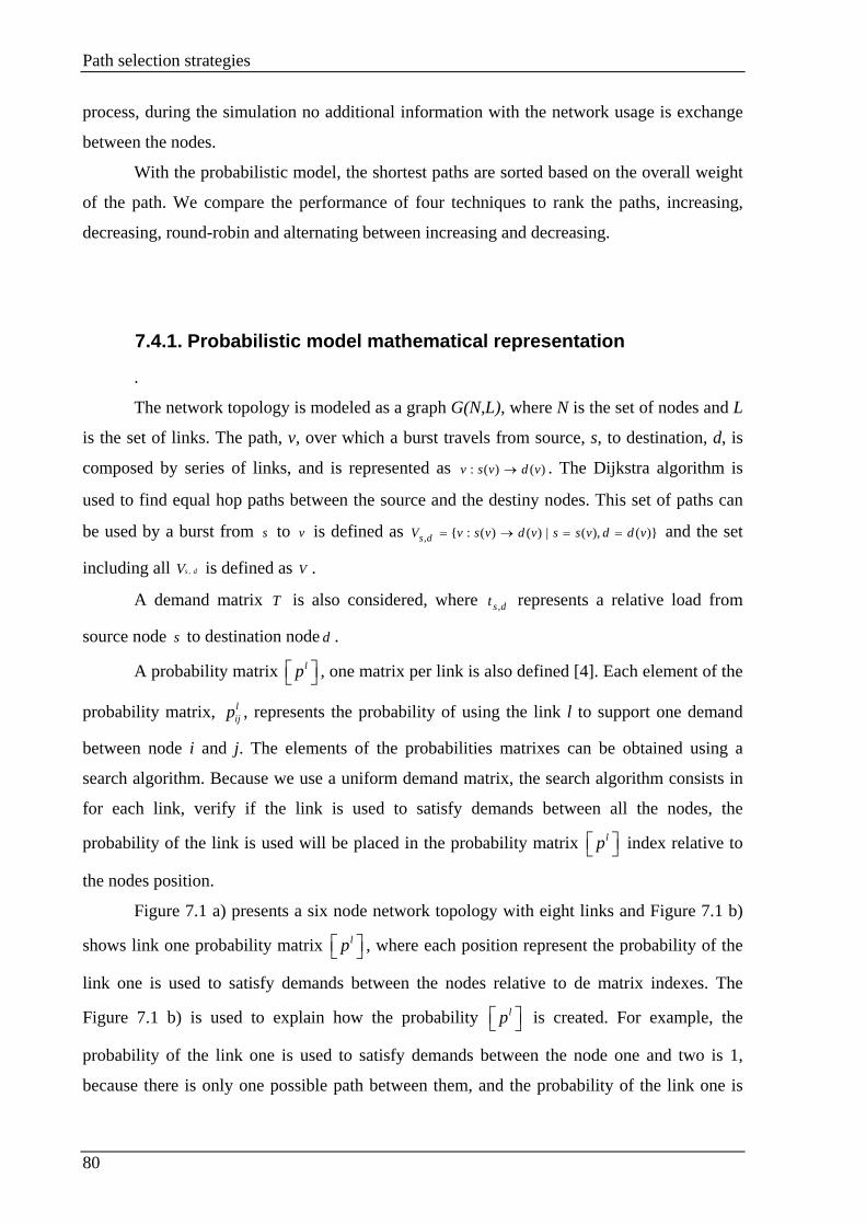
Path selection strategies
80
process, during the simulation no additional information with the network usage is exchange
between the nodes.
With the probabilistic model, the shortest paths are sorted based on the overall weight
of the path. We compare the performance of four techniques to rank the paths, increasing,
decreasing, round-robin and alternating between increasing and decreasing.
7.4.1. Probabilistic model mathematical representation
.
The network topology is modeled as a graph G(N,L), where N is the set of nodes and L
is the set of links. The path, v, over which a burst travels from source, s, to destination, d, is
composed by series of links, and is represented as )()(: vdvsv → . The Dijkstra algorithm is
used to find equal hop paths between the source and the destiny nodes. This set of paths can
be used by a burst from s to v is defined as )}(),(|)()(:{, vddvssvdvsvV ds ==→= and the set
including all dsV , is defined as V .
A demand matrix T is also considered, where dst , represents a relative load from
source node s to destination node d .
A probability matrix lp , one matrix per link is also defined [4]. Each element of the
probability matrix, lijp , represents the probability of using the link l to support one demand
between node i and j. The elements of the probabilities matrixes can be obtained using a
search algorithm. Because we use a uniform demand matrix, the search algorithm consists in
for each link, verify if the link is used to satisfy demands between all the nodes, the
probability of the link is used will be placed in the probability matrix lp index relative to
the nodes position.
Figure 7.1 a) presents a six node network topology with eight links and Figure 7.1 b)
shows link one probability matrix lp , where each position represent the probability of the
link one is used to satisfy demands between the nodes relative to de matrix indexes. The
Figure 7.1 b) is used to explain how the probability lp is created. For example, the
probability of the link one is used to satisfy demands between the node one and two is 1,
because there is only one possible path between them, and the probability of the link one is

Path selection strategies
81
used is to satisfy demands between the nodes one and four is ½, because there are two equal
hop paths between this nodes. All lp matrixes are constructed using this technique.
1
0 1 1 1/ 2 0 01 0 0 0 0 01 0 0 0 0 0
1/ 2 0 0 0 0 00 0 0 0 0 00 0 0 0 0 0
p
=
a) b)
Figure 7.1- a) A network topology, represented by a graph; b) the matrix lp for link 1 (l=1).
The probability matrix lp is the most important element of the probabilistic model
because it will sum all the matrix fields to obtain the links weight. The link l weight
mathematical representation is:
,1 1
N Nl
l i ji j
W p= =
=∑∑ .
The weight of a given path composed by L links is the sum of the weight of the links
that compose the path. This weight is directly proportional with the probability of the link
being used.
The next step before the simulation start is sorting the paths by its weight. The
probabilistic model performance is tested sorting the paths using different strategies.
7.5. Probabilistic model performance evaluation
The sorting strategy influences the overall job dropping probability. This section
presents the performance evaluation of four sorting strategies.
The path weight is obtained summing the weight of all the links that belong to the
path. For each source end node pair, the shortest paths are ranked. The sorting techniques
4 1
2 3
6 5
Link 1 Link 2
Link 3
Link 4 Link 5
Link 8 Link 7
Link 6
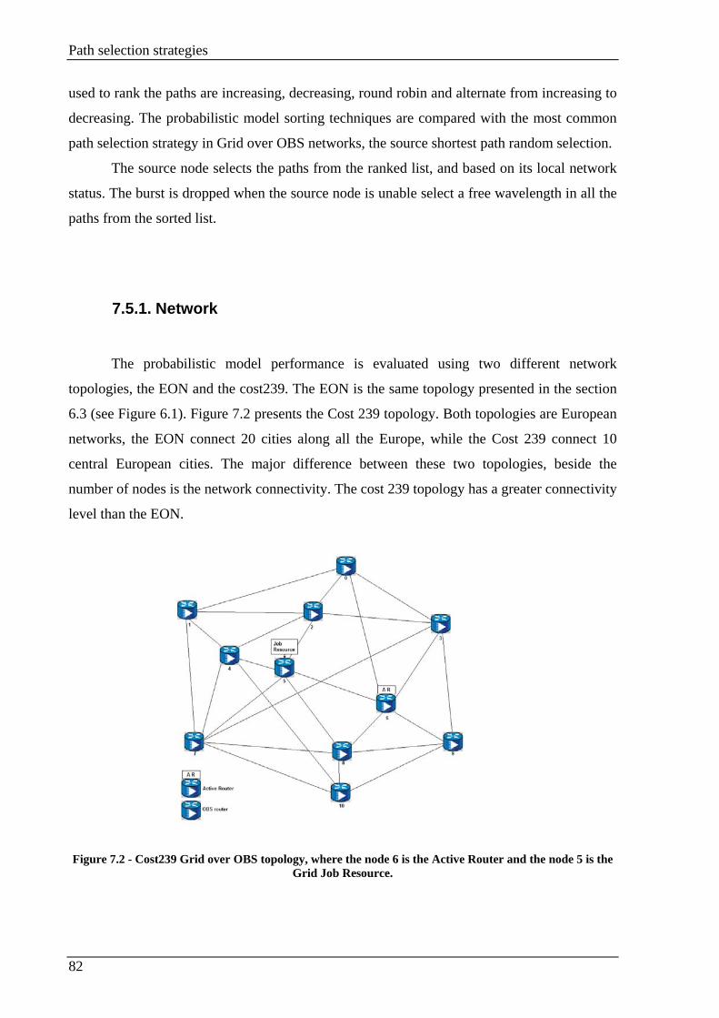
Path selection strategies
82
used to rank the paths are increasing, decreasing, round robin and alternate from increasing to
decreasing. The probabilistic model sorting techniques are compared with the most common
path selection strategy in Grid over OBS networks, the source shortest path random selection.
The source node selects the paths from the ranked list, and based on its local network
status. The burst is dropped when the source node is unable select a free wavelength in all the
paths from the sorted list.
7.5.1. Network
The probabilistic model performance is evaluated using two different network
topologies, the EON and the cost239. The EON is the same topology presented in the section
6.3 (see Figure 6.1). Figure 7.2 presents the Cost 239 topology. Both topologies are European
networks, the EON connect 20 cities along all the Europe, while the Cost 239 connect 10
central European cities. The major difference between these two topologies, beside the
number of nodes is the network connectivity. The cost 239 topology has a greater connectivity
level than the EON.
Figure 7.2 - Cost239 Grid over OBS topology, where the node 6 is the Active Router and the node 5 is the
Grid Job Resource.
Path selection strategies
83
WDM fibers with four wavelengths are considered, one of which is used exclusively
for signaling transmission, while the other 3 are used for the data transmission. A non
wavelength conversion scenario is considered.
The job requests are generated as a Poisson process with mean arrival rate λ
arrivals/ms. Job sizes are distributed according to a exponential distribution with mean 1/μ.
The performance is compared with the JET-OBS signaling which selects the paths
randomly from the shortest paths.
7.5.2. Sorting technique: increasing
In this strategy the paths are ranked based on their weight; the first chosen is the one
with less overall weight. To test the path selection strategy performance we use three different
network scenarios. The scenario presented in Figure 6.1 and in Figure 7.2 with the node 6 the
Active Router and two different locations for the Grid Job Resource (node 5 and 7). This two
locations are considered in order to assess the performance of the Cost 239 topology using a
resource in a central location with less connectivity (node 5), or the Grid job resource in a
network edge with higher connectivity (node 7).
Figure 7.3 present the job blocking probability for the EON scenario presented in
Figure 6.1. We fixed the job duration (0.2, 0.6, 1.0, 2.0, 5.0, 10.0, 20.0 and 40.0 ms) and
variable interval between the generation of the Jobs.
Figure 7.4 and Figure 7.5 show the equivalent results for the cost 239 network
topology scenarios. In Figure 7.4, we verify the performance of the network with the Active
Router placed in the node 6 and the Grid Job Resource in the node 5, while in Figure 7.5; the
Active Router is also the node 5, while the Job Resource is the node 7.

Path selection strategies
84
Figure 7.3 - Job blocking probability versus load using EON network with the node 14 as Active Router and the node 4 is the job resource. The paths are ranked by is weight for the job durations of a) 0.2, 0.5,
1.0 and 2.0ms, b) 5.0, 10.0, 20.0 and 40.0 ms and c) 5.0, 10.0, 20.0 and 40.0 ms for lower loads.
Figure 7.4 - Job blocking probability versus load using Cost 239 network with the node 6 as Active Router
and the node 5 is the job resource. The paths are ranked by is weight for the job durations of a) 0.2, 0.5, 1.0 and 2.0ms, b) 5.0, 10.0, 20.0 and 40.0 ms and c) 5.0, 10.0, 20.0 and 40.0 ms for lower loads.
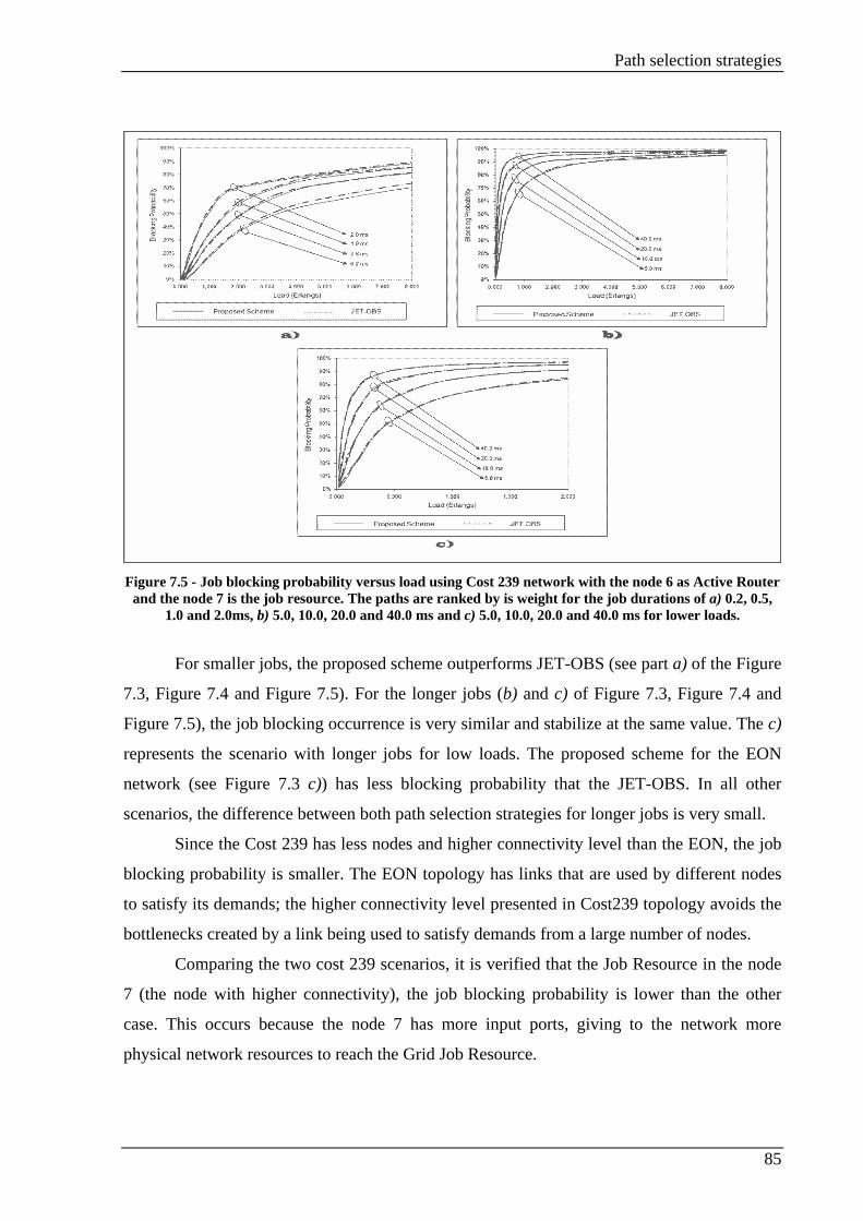
Path selection strategies
85
Figure 7.5 - Job blocking probability versus load using Cost 239 network with the node 6 as Active Router
and the node 7 is the job resource. The paths are ranked by is weight for the job durations of a) 0.2, 0.5, 1.0 and 2.0ms, b) 5.0, 10.0, 20.0 and 40.0 ms and c) 5.0, 10.0, 20.0 and 40.0 ms for lower loads.
For smaller jobs, the proposed scheme outperforms JET-OBS (see part a) of the Figure
7.3, Figure 7.4 and Figure 7.5). For the longer jobs (b) and c) of Figure 7.3, Figure 7.4 and
Figure 7.5), the job blocking occurrence is very similar and stabilize at the same value. The c)
represents the scenario with longer jobs for low loads. The proposed scheme for the EON
network (see Figure 7.3 c)) has less blocking probability that the JET-OBS. In all other
scenarios, the difference between both path selection strategies for longer jobs is very small.
Since the Cost 239 has less nodes and higher connectivity level than the EON, the job
blocking probability is smaller. The EON topology has links that are used by different nodes
to satisfy its demands; the higher connectivity level presented in Cost239 topology avoids the
bottlenecks created by a link being used to satisfy demands from a large number of nodes.
Comparing the two cost 239 scenarios, it is verified that the Job Resource in the node
7 (the node with higher connectivity), the job blocking probability is lower than the other
case. This occurs because the node 7 has more input ports, giving to the network more
physical network resources to reach the Grid Job Resource.
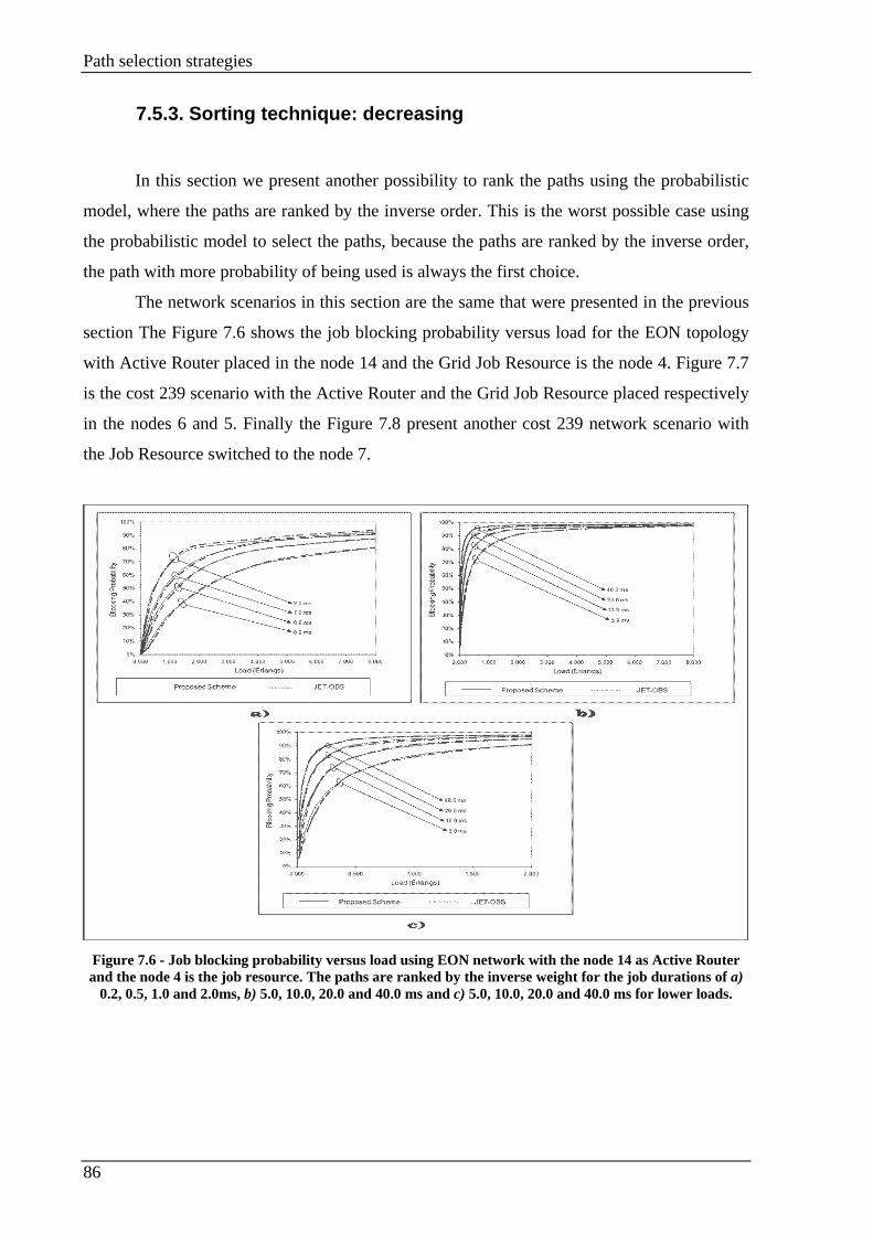
Path selection strategies
86
7.5.3. Sorting technique: decreasing
In this section we present another possibility to rank the paths using the probabilistic
model, where the paths are ranked by the inverse order. This is the worst possible case using
the probabilistic model to select the paths, because the paths are ranked by the inverse order,
the path with more probability of being used is always the first choice.
The network scenarios in this section are the same that were presented in the previous
section The Figure 7.6 shows the job blocking probability versus load for the EON topology
with Active Router placed in the node 14 and the Grid Job Resource is the node 4. Figure 7.7
is the cost 239 scenario with the Active Router and the Grid Job Resource placed respectively
in the nodes 6 and 5. Finally the Figure 7.8 present another cost 239 network scenario with
the Job Resource switched to the node 7.
Figure 7.6 - Job blocking probability versus load using EON network with the node 14 as Active Router and the node 4 is the job resource. The paths are ranked by the inverse weight for the job durations of a)
0.2, 0.5, 1.0 and 2.0ms, b) 5.0, 10.0, 20.0 and 40.0 ms and c) 5.0, 10.0, 20.0 and 40.0 ms for lower loads.
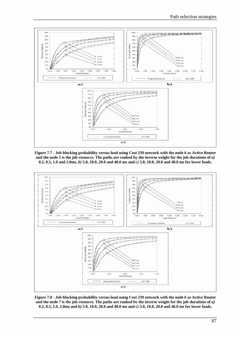
Path selection strategies
87
Figure 7.7 - Job blocking probability versus load using Cost 239 network with the node 6 as Active Router and the node 5 is the job resource. The paths are ranked by the inverse weight for the job durations of a)
0.2, 0.5, 1.0 and 2.0ms, b) 5.0, 10.0, 20.0 and 40.0 ms and c) 5.0, 10.0, 20.0 and 40.0 ms for lower loads.
Figure 7.8 - Job blocking probability versus load using Cost 239 network with the node 6 as Active Router and the node 7 is the job resource. The paths are ranked by the inverse weight for the job durations of a)
0.2, 0.5, 1.0, 2.0ms and b) 5.0, 10.0, 20.0 and 40.0 ms and c) 5.0, 10.0, 20.0 and 40.0 ms for lower loads.

Path selection strategies
88
In the three scenarios presented in this section for the higher job durations (part b) and
c) of the Figure 7.6, Figure 7.7 and Figure 7.8), and higher loads (part a)) the both schemes
stabilize at the same value, and for lower loads (part c)) the random path selection used by the
JET-OBS presents a lower job blocking probability.
For small job duration (part a) of the Figure 7.6, Figure 7.7 and Figure 7.8) the job
blocking probability is smaller for the proposed scheme, although the gain is small. The cost
239 scenarios, the difference between job blocking probabilities is higher than the obtained
with the EON, because the cost network present a higher connectivity. The gain of this path
sorting strategy is smaller than the one obtained sorting the paths by its weight (comparing the
a) part of Figure 7.4 and Figure 7.5 with a) part of Figure 7.7 and Figure 7.8).
A random choice is a better choice than the inverse order sorting, because the paths
with higher dropping probability are always the first choice, while in JET, the paths are
selected randomly. All the paths have the same probability of being chosen.
7.5.4. Sorting technique: round robin
The round robin path selection strategy consists in each node; sorted by the weight the
paths used to reach the Grid Job Resource. Next, for each job, the source node select the path
by a round robin way, first use the first path, for the second job, the second path, and so on
until the last available path, and then it will return to the first path, restarting from the
beginning again. Using a round robin strategy, the nodes do not use always the optimums
paths. The optimum path can be the optimum path of several source–end node pare. All the
nodes will use all the paths in the list, once at a time. With this technique we try to avoid the
possible bottlenecks created on the most popular links, selecting the paths in a circular
technique.
Figure 7.9, Figure 7.10 and Figure 7.11 present the job blocking probability versus
load. In Figure 7.9 use the network scenario presented in Figure 6.1. Figure 7.10 and Figure
7.11 use a cost 239 topology with the Active Router placed in the node 6 and the Job
Resource are the nodes 5 and 7 respectively.
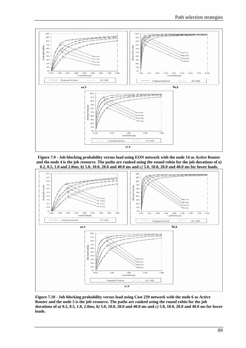
Path selection strategies
89
Figure 7.9 - Job blocking probability versus load using EON network with the node 14 as Active Router
and the node 4 is the job resource. The paths are ranked using the round robin for the job durations of a) 0.2, 0.5, 1.0 and 2.0ms, b) 5.0, 10.0, 20.0 and 40.0 ms and c) 5.0, 10.0, 20.0 and 40.0 ms for lower loads.
Figure 7.10 - Job blocking probability versus load using Cost 239 network with the node 6 as Active Router and the node 5 is the job resource. The paths are ranked using the round robin for the job durations of a) 0.2, 0.5, 1.0, 2.0ms, b) 5.0, 10.0, 20.0 and 40.0 ms and c) 5.0, 10.0, 20.0 and 40.0 ms for lower loads.
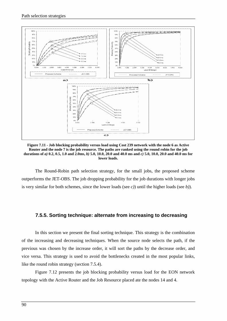
Path selection strategies
90
Figure 7.11 - Job blocking probability versus load using Cost 239 network with the node 6 as Active Router and the node 7 is the job resource. The paths are ranked using the round robin for the job
durations of a) 0.2, 0.5, 1.0 and 2.0ms, b) 5.0, 10.0, 20.0 and 40.0 ms and c) 5.0, 10.0, 20.0 and 40.0 ms for lower loads.
The Round-Robin path selection strategy, for the small jobs, the proposed scheme
outperforms the JET-OBS. The job dropping probability for the job durations with longer jobs
is very similar for both schemes, since the lower loads (see c)) until the higher loads (see b)).
7.5.5. Sorting technique: alternate from increasing to decreasing
In this section we present the final sorting technique. This strategy is the combination
of the increasing and decreasing techniques. When the source node selects the path, if the
previous was chosen by the increase order, it will sort the paths by the decrease order, and
vice versa. This strategy is used to avoid the bottlenecks created in the most popular links,
like the round robin strategy (section 7.5.4).
Figure 7.12 presents the job blocking probability versus load for the EON network
topology with the Active Router and the Job Resource placed ate the nodes 14 and 4.
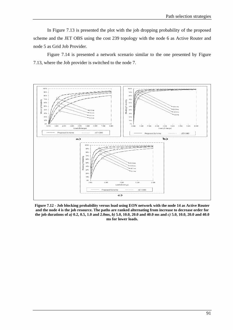
Path selection strategies
91
In Figure 7.13 is presented the plot with the job dropping probability of the proposed
scheme and the JET OBS using the cost 239 topology with the node 6 as Active Router and
node 5 as Grid Job Provider.
Figure 7.14 is presented a network scenario similar to the one presented by Figure
7.13, where the Job provider is switched to the node 7.
Figure 7.12 - Job blocking probability versus load using EON network with the node 14 as Active Router and the node 4 is the job resource. The paths are ranked alternating from increase to decrease order for the job durations of a) 0.2, 0.5, 1.0 and 2.0ms, b) 5.0, 10.0, 20.0 and 40.0 ms and c) 5.0, 10.0, 20.0 and 40.0
ms for lower loads.
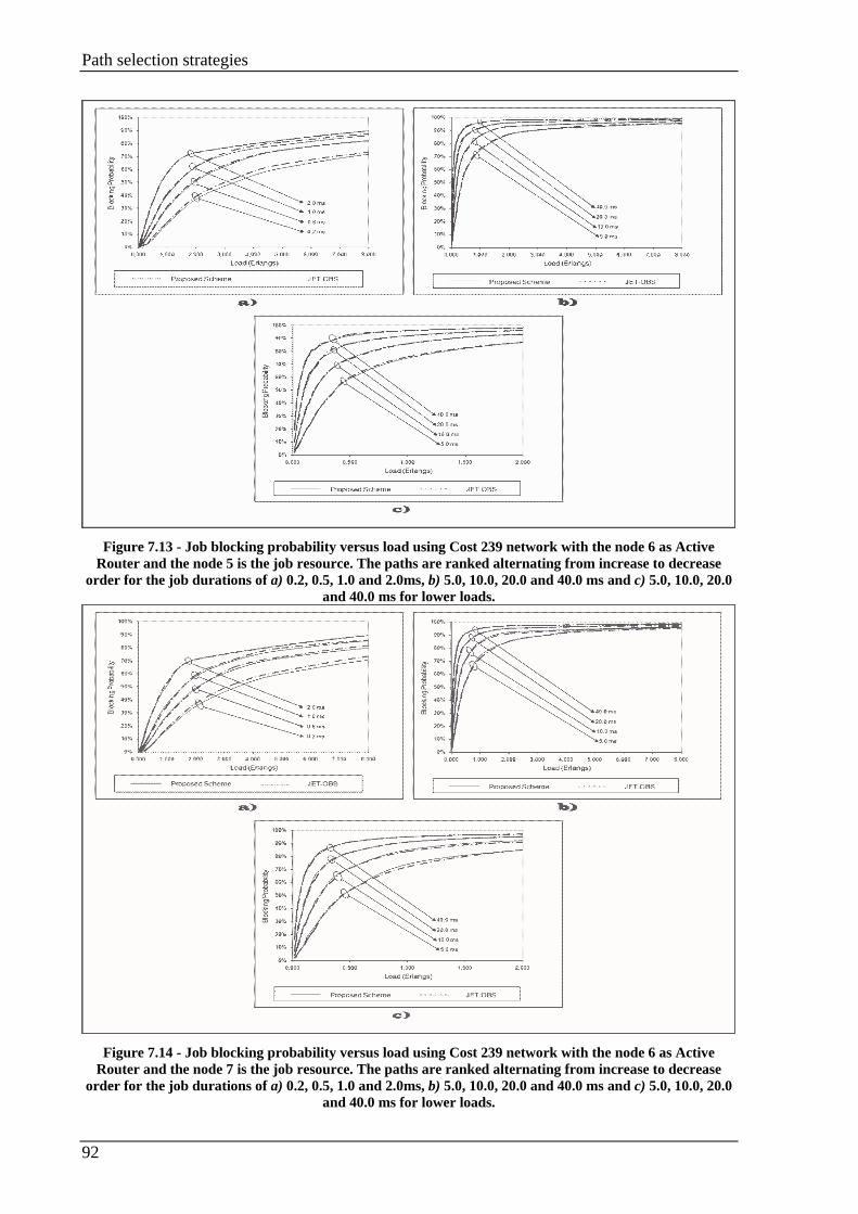
Path selection strategies
92
Figure 7.13 - Job blocking probability versus load using Cost 239 network with the node 6 as Active
Router and the node 5 is the job resource. The paths are ranked alternating from increase to decrease order for the job durations of a) 0.2, 0.5, 1.0 and 2.0ms, b) 5.0, 10.0, 20.0 and 40.0 ms and c) 5.0, 10.0, 20.0
and 40.0 ms for lower loads.
Figure 7.14 - Job blocking probability versus load using Cost 239 network with the node 6 as Active
Router and the node 7 is the job resource. The paths are ranked alternating from increase to decrease order for the job durations of a) 0.2, 0.5, 1.0 and 2.0ms, b) 5.0, 10.0, 20.0 and 40.0 ms and c) 5.0, 10.0, 20.0
and 40.0 ms for lower loads.

Path selection strategies
93
For small jobs duration, the proposed scheme outperforms the JET-OBS (part a) of
Figure 7.12, Figure 7.13 and Figure 7.14). The gain is more significant in the Cost 239
scenarios, because the higher network connectivity make select a larger group of different
links to reach the Job Resource, producing an inferior overall job dropping percentage.
For larger jobs, presented in b) and c) plots of the Figure 7.12, Figure 7.13 and Figure
7.14, the proposed scheme have a job dropping probability very similar to the one obtained by
JET-OBS and both schemes stabilize at the same value, for lower (see plots c)) and higher
loads (see plots b)).
7.5.6. Comparison between sorting techniques
Figure 7.15, Figure 7.16 and Figure 7.17 show the comparison between the four
sorting techniques, for small jobs (0.2, 0.6 and 1.0 ms) and lower loads. This scenario was
chosen, because it is the scenario that presents the most significant differences between them.
Each of the graphics represents a different network topology. The results for the EON are
shown in Figure 7.15, Figure 7.16 corresponds to cost239 with the node 6 acting like Active
Router and the node 5 is the Job Resource and finally Figure 7.17 corresponds to cost239 with
node 6 acting as Active Router and node 7 the job provider.
Figure 7.15 - Comparison between the 4 strategies for small bursts durations and low loads, for EON
topology with the Active router in node 14 and the node 4 Job Provider.
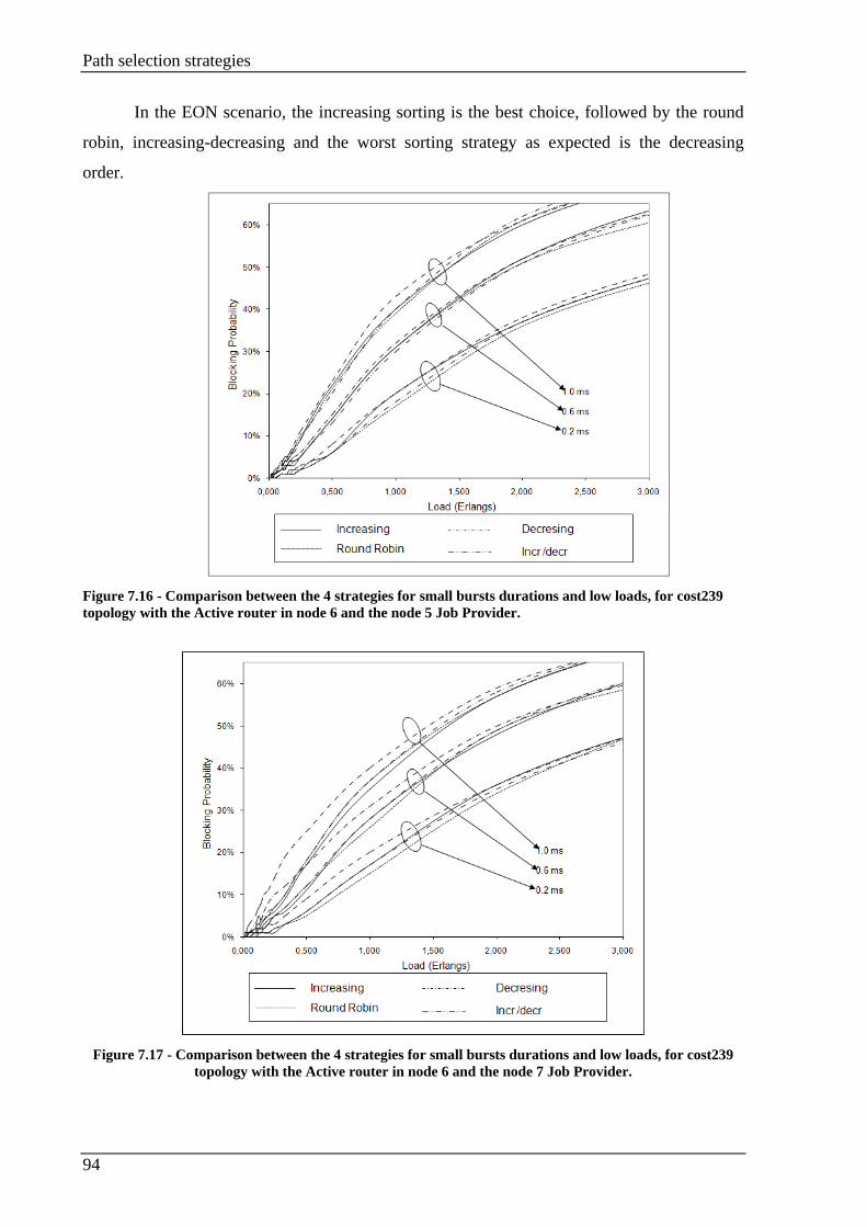
Path selection strategies
94
In the EON scenario, the increasing sorting is the best choice, followed by the round
robin, increasing-decreasing and the worst sorting strategy as expected is the decreasing
order.
Figure 7.16 - Comparison between the 4 strategies for small bursts durations and low loads, for cost239 topology with the Active router in node 6 and the node 5 Job Provider.
Figure 7.17 - Comparison between the 4 strategies for small bursts durations and low loads, for cost239
topology with the Active router in node 6 and the node 7 Job Provider.

Path selection strategies
95
Comparing the Figure 7.16 and Figure 7.17, both have a result very similar, since the
network used is the same only the job resource is place on a different place. The job provider
location makes the difference between the sorting strategies. Blocking is higher when the job
provider is place in the node 7, the one with higher connectivity level in the network. Except
for low job durations (0.2 ms), the increasing order and the round-robin are almost the same.
For the Cost239 topology the increasing order is only the best choice when the jobs are larger
(1 ms), for all the other cases, the round-robin or the increasing decreasing are the best sorting
strategies. Like in the EON, the worst sorting strategy is the decreasing, because the paths
with higher probability of being used are always the first choice.
The difference between the results presented in the Figure 7.15 which use the EON
topology and the figures that use cost239 (Figure 7.16 and Figure 7.17) occur because the
cost239 has a higher connectivity level.
7.6. Chapter summary
In this chapter we present our path selection strategy. It is a non adaptative strategy
which use a probabilistic model for the link demands to predict the network load. This
strategy estimates the probability of the usage of a link by make the probability of every links
is being used to satisfy demands from all nodes to all nodes. The path selection strategy
performance was verified sorting the paths by it weight using four techniques (increasing,
decreasing, round robin or alternating from increasing to decreasing).
Analyzing all the sorting strategies evaluated in the sections 7.5 we verify that our
path selection strategy for lower packet size the job blocking probability is smaller to the one
obtained by the JET-OBS in all the scenarios except using decreasing sorting in the EON
network (Figure 7.6). Because the path selection strategy based on the probabilistic model
using the small job sizes outperform the JET-OBS using random source routing, is very
suitable for the GOBS consumer scenarios, where the used jobs are small. We have shown
that the most efficient path sorting techniques for all the scenarios considered is the
increasing.
Conclusions and Future work
96
Chapter 8. Conclusions and Future work
8.1. Conclusion
This dissertation proposes, discusses and evaluates a signaling scheme for Grid over
Optical Burst Switching networks controlled by an Active Router. The Active Router is a
network entity with a global knowledge within a network domain. The Active Router is
responsible to select the Grid Job Resource used to resolve the jobs.
We present two different strategies to reduce the job dropping occurrence. The first
strategy is the novel signaling scheme presented in Chapter 6. The second strategy is
presented in Chapter 7. In this second strategy, the Active Router only select the Grid
Resource used to resolve the path, and the path used to reach it is selected based on the
probabilistic model for the link demands.
In the first strategy, the Active Router has an important role in the job dropping
reduction. The Active Router selects the path used by the Data Burst to reach the Grid Job
Resource based on the network actual status. The Active Router maintains the network status
always updated. Since the status is always updated, the bursts are only dropped when is not
possible connect the source to the end node. In section 6.5.1 it is compared the job blocking
probability of the proposed scheme with the JET-OBS with random path selection, which is
the signaling scheme most commonly used in OBS networks. The proposed scheme presents
always a lower job blocking probability. In this strategy it is also studied the influence of a
signaling buffer in the Active Router. The signaling buffer is used by the Active Router to
retain the Grid Resource Requests. The signaling queue usage makes the Active Router
perform only one request at a time. Comparing the scenarios with signaling queue or without,
the scenario with the buffer have less dropping occurrence, because the paths are resolved
using resources that were not free in the bufferless scenario. The resource availability occurs
because the Active Router only resolves one request at each processing time.
Another study associated with this signaling scheme is the reservation time. The
reservation time considered is the used time since the job creation until start the burst
transmission. The reservation time is an important study because the reservation time in OBS
networks needs to be as low as possible. We consider two reservation time scenarios, use the

Conclusions and Future work
97
signaling buffer in the Active Router or use a network with no buffering scenario. The
reservation time in the network without buffer is always inferior to the one performed by JET-
OBS. This reduction in the reservation time is caused because the Active Router is
responsible to start the reconfiguration process, while in JET-OBS the Grid Client start the
network configuration process. In the buffered scenario, the principal consequence introduced
by the buffer is the reservation time increase. The buffer introduction causes a reduction in the
job dropping probability introducing longer reservations times.
The second scenario is presented in Chapter 7. The Active Router is responsible to
select Grid Job Resource for each job. The path used to connect the Grid client to the Grid
Resource is selected by the Grid client based on a probabilistic model for the link demands.
The probabilistic model is used to predict a possible network usage based on the demands
from all nodes to all nodes. The probabilistic model results in a weight for each link. The
weight represents the possibility of the link being used. The paths weight is obtained
summing the weight of the used links. The source node rank the group of the shortest paths
based its overall weight. The strategies presented to sort the paths are increasing, decrease,
round robin and alternate from increasing to decreasing. The probabilistic model performance
is tested comparing the ranking strategies based on the probabilistic model job blocking
probability with the random path selection. The strategy with better performance is the
increasing order, because the paths are ranked by their weight, the path with less weight is the
first to be selected. The worst strategy is the decreasing order where the worst paths are
always the first choice.
This master dissertation presents a consumer scenario for Grid over OBS networks.
The consumer scenarios are characterized by having low computational requirements and
smaller durations. The strategies presented in this work are very suitable for consumer
scenarios, because present the fewer job blocking probabilities for smaller jobs duration.
Conclusions and Future work
98
8.2. Future work
The proposed scheme presented in Chapter 6 and Chapter 7 reduces the burst blocking
probability when compared with the JET-OBS. To increase the wavelength reservation
efficiency it would be interesting to explore the burst scheduling algorithms presented in
section 2.7. With the introduction of the burst scheduling algorithms the wavelengths usage is
improved and consequently the burst blocking probability reduced.
The buffers used in this work are infinite. In real networks infinite buffer do not exist.
A more real approach is introducing a buffer with different classes of services. The services
with higher priority are always resolved first and when the resolution time expires the
requests should be popped from the buffer and the job retransmission or dropping is left for
upper network layer resolution.
References
99
References
[1] C. Qiao, and M. Yoo, “Optical burst switching: A new paradigm for an optical
Internet,” Journal High Speed Networks, vol. 8, nº. 1, pp. 69-94, March 1999.
[2] M. De Leenheer, P. Thysebaert, B. Volckaert, F. De Turck, B. Dhoedt, P.
Demeester, D. Simeonidou, R. Nejabati, G. Zervas, D. Klonidis, and M. J.
O'Mahony, "A View on Enabling-Consumer Oriented Grids through Optical
Burst Switching," Communications Magazine, IEEE, vol. 44, no. 3, pp. 124-
131, March 2006.
[3] D. Simeonidou, R. Nejabati, G. Zervas, D. Klonidis, A. Tzanakaki, and M.J.
O’Mahony, “Dynamic optical-network architectures and technologies for
existing and emerging grid services”, Journal of Lightwave Technology, vol.
23, no. 10, pp. 3347-3357, October 2005.
[4] A. R. P. Correia, C. Pavan, A.N. Pinto, “A Probabilistic Model for the
Demands on Link on Mesh Optical Networks,” SEON'06, IV Symposium on
Enabling Optical Networks and Sensors, Porto, Portugal, pp. 43-44, June 16,
2006.
[5] F. Farahmand, Contention resolution and burst grooming strategies in layered
optical burst-switched networks, PHD Thesis, August 2005.
[6] G. H. Sasaki, and O. Gerstel, “Minimal cost WDM SONET rings that
guarantee no blocking,” Optical Networks Magazine, vol. 1, no. 4 October
2000.
[7] C. DeCasutis, “Dense wavelength division multiplexing for parallel sysplex
and metropolitan/storage area networks,” Optical Networks, vol. 2, no. 1, pp.
69-90, January/February 2001.
[8] I. Foster, and C. Kesselman, The Grid: Blueprint for a New Computing
Infrastructure, Morgan Kaufmann, San Francisco, California 1999.
[9] B. Mukherjee, Optical Communications Networks, McGraw-Hill, 1997.
[10] Y. Xiong, M. Vandenhoute, and H. Cankaya, “Control architecture in optical
burst-switched WDM networks,” IEEE Journal on selected Areas in
Communications”, vol. 18, pp. 1838-1851, October 2000.

References
100
[11] Y. Chen, C. Qiao, and X. Yu, “Optical burst switching: A new area in optical
networking research,” IEEE Netw. Mag., vol. 18, no. 3, pp. 16–23, May/June
2004.
[12] E. A. Varvarigos, and V. Sharma, “The ready-to-go virtual circuit protocol: A
loss-free protocol for multigigabit networks using FIFO buffers,” IEEE/ACM
Trans. Networking, vol. 5, pp. 705–718, October. 1997.
[13] I. Widjaja, “Performance analysis of burst admission-control protocols,”
Proceedings Inst. Elect. Eng. Communications, vol. 142, pp. 7–14, February
1995.
[14] S. K. Korotky, “Network global expectation model: a statistical formalism for
quickly quantifying network needs and costs,” Journal of Lightwave
Technology., vol. 22, pp. 703-722, March 2004.
[15] M. Duser, and P. Bayvel, “Modelling of optical burst- switched packet
networks,” Proceedings of the European Conference on Optical
Communications, vol. 2, pp. 23-24, September 2000.
[16] M. Duser, and P. Bayvel, “Bandwidth utilization and wavelength re-use in
WDM optical burst-switched networks,” Proceedings of IFIP 5th Working
Conference on Optical Network design and Modelling, vol. 1, pp. 23-24,
February 2001.
[17] M. Duser, and P. Bayvel, “Performance of a dynamically wavelength routed
optical burst switched network,” IEEE Photonics Technology Letters, vol. 14,
pp. 239–241, February 2002.
[18] M. Duser, E. Kozlovsky, R, Killey and P. Bayvel, “Design trade-offs in optical
burst switched packet networks in dynamic wavelength,” Proceedings of IFIP
5th Working Conference on Optical network Design and Modelling, vol.1,
February 2001.
[19] E. Kozlovsky, M. Duser, I. de Miguel, and P. Bayvel, “Analysis of burst
scheduling for dynamic wavelength,” Lasers and Electro-Optics Society, vol.1,
pp. 161-162, 2001.
[20] D. Steveson, and I. Baldine, “Just in time signalling definition (Jumpstart),”
Jumpstart, an NSA funded project, January 2002.
[21] J. Turner, “Terabit burst switching”, Journal of High Speed Networks, 1999.

References
101
[22] P. Bayvel, “Wavelength routing and optical burst switching in the design of
future optical network architectures,” Proceedings of the 27th European
Conference on Optical Communications, vol. 4, pp. 616-619, 2001.
[23] I. de Miguel, M. Duser, and P. Bayvel, “Traffic load bounds for optical burst-
switched networks with dynamic wavelength allocation,” Proceedings of IFIP
5th Working Conference on Optical Network Design and Modelling, vol. 1,
February 2001.
[24] Y. Xiong, M. Vandehnoute, and H. Cankaya, “Control Architecture in Optical
Burst-Switched WDM Networks,” IEEE JSAC, vol. 18, pp1838-1851, October
2000.
[25] J. Xu et al, "Efficient Channel Scheduling Algorithm in Optical Burst
Switched Networks," Proc. INFOCOM, vol.3, pp. 2268-2278, 2003.
[26] J. Y. Wei and R. I. McFarland, “Just-in-time signalling for WDM optical burst
switching networks (Invited Paper),” Journal of Lightwave Technology,
Special Issue on Optical Networks, vol. 18, pp. 2019–2037, December 2000.
[27] J. Teng and G. N. Rouskas, “A comparison of the JIT, JET, and Horizon
wavelength reservation schemes on a single OBS node,” Proceedings of the
First International Workshop on Optical Burst Switching, October 2003.
[28] S. R. Amstutz, “Burst Switching: An Introduction,” IEEE Communications
Magazine, vol. 21, pp. 36-42, November 1983.
[29] F. Travostino, J. Mambretti, and G. K. Edwards, Grid Networks enabling grids
with advanced communications technology, John Wiley & Sons, 2006.
[30] Global Grid Forum website: http://www.ogf.org/, visited on November 2009.
[31] K. Czajkowski, S. Fitzgerald, I. Foster, and C. Kesselman, “Grid Information
Services for Distributed Resource Sharing,” Proceedings of the 10th IEEE
International Symposium on High Performance Distributed computing
(HPDC-10), pp. 181-194, August 2001.
[32] I. Foster, C. Kesselman, Tsudik, and S. Tuecke, “A Security Architecture for
Computational Grids,” Proceedings of the 5th ACM Conference on Grid and
Communications Security Conference, pp. 83-92, 1998.
[33] I. Foster, H. Kishimoto, A. Savva, D. Berry, A. Dijaoui, A. Grimshaw, B.
Horn, F. Maciel, F. Siebenlist, R. Subramaniam, J. Tredwell, and J. Von Reich,
“Open grid Services Architecture Version1.0,” Grid Forum Document,
January, 2005.
References
102
[34] A. Andrieux, K.Czajkowski, A. Dan, K. Keeahey, H. Ludwing, J. Pruyme, J.
Rofrano, S. Tueke, and M. Xu, “Web Services Agreement Specification (WS-
Agreement),” Grid Forum Document, March, 2007.
[35] World Wide Web Consortium website: http://www.w3.org/, visited on
December 2008.
[36] Extensible Markup Language at World Wide Web Consortium, website:
http://www.w3.org/XML/, visited on January 2009.
[37] Simple Object Access Protocol at World Wide Web Consortium, website:
http://www.w3.org/2000/xp/Group/, visited on January 2009.
[38] Web Services Description Language at World Wide Web Consortium, website:
http://www.w3.org/2002/ws/desc/, visited on January 2009
[39] IPShere forum, website: http://www.ipsphereforum.org/, visited on February
2009.
[40] Message Passing Interface Forum, http://www.mpi-forum.org/, visited on
February 2009.
[41] Common Information Model (CIM) version 2.20, Distributed Management
Task Force, website: http://www.dmtf.org/standards/cim/cim_schema_v220/,
visited on February 2009.
[42] International Telecommunications Union, website:
http://www.itu.int/net/home/index.aspx, visited on February 2009.
[43] Institute of Electrical and Electronics Engineering, website:
http://www.ieee.org/portal/site, visited on February 2009.
[44] R. Nejabati, “Grid Optical Burst Switched Networks (GOBS),” Global Grid
Forum Draft, April 2008.
[45] M. Maimour, and C. Pham, “Dynamic replier active reliable multicast
(DyRAM),” in Proc. 7th IEEE Symp. Computers and Communications (ISCC),
Taormina, Italy, pp. 275–282 2002.
[46] J. Gaither, “300-Pin MSA Bit-Error Rate Tester for the ML10G Board and
RocketPHY Transceiver,” XILINX, Application note: XAPP677 Virtex-II Pro
family, January 2004.
[47] D. Simeonidou, B. St. Arnaud, M. Beck, B. Berde, F. Dijkstra, D. B. Hoang,
G. Karmous-Eduards, T. Lavian, J. Leigh, J. Manbretti, R. Nejabati, and F.
Travostino, “Optical Network Infrastructure for Grid,” Global Grid Forum
Draft, August 2004.
References
103
[48] C. Partridge, T. Mendez, W. Milliken, “Host Anycasting Service,” IETF RFC
1546, November 1993.
[49] S. Bhattacharjee, M. H. Ammar, E. Sahan, and Z. Fei, “Application-Layer
Anycasting,” Proceedings. of IEEE Infocom’97, April 1997.
[50] R. Nejabati, G. Zervas, G. Dimitriades and D. Simeonidou, “Programmable
Optical Burst Switched Networks: A Novel Infrastructure for Grid services,”
5th IEEE/ACM Int. Symposium Cluster Computing Grid (CCGrid), Cardiff,
U.K., pp. 993-999, May 2005.
[51] M. Yoo and C. Qiao, “Just-enough-time (JET): A high speed protocol for
busty traffic in optical networks,” in IEEE/LEOS Technol. Global Information
Infrastructure, pp. 26-27, August 1997.
[52] M. Maimour and C. Pham, “Dynamic replier active reliable multicast
(DyRAM),” in Proc. 7th IEEE Symposium Computers and Communications
(ISCC), pp. 78-282, 2002.
[53] A. Abbas, “GRID COMPUTING: A Practical Guide to Technology and
Applications,” Charles River Media, Inc., 2004.
[54] V. P. Kumar, T. V. Lakshman, and D. Stiliadis, “Beyond best effort: Router
architecture for Differentiated Services of Tomorrow’s Internet,” IEEE
Communication Magazine, vol. 36, pp. 152-164, May 2003.
[55] J. M. Gabriagues and J. B. Jacob, “Exploitation of the wavelength domain for
photonic switching in IBCN,” Proceedings of .ECOC’91, vol. 2, pp. 59–66,
September 1991.
[56] Y. Sun, T. Hashiguchi, V.Q. Minh, X. Wang, H. Morikawa and T. Aoyama,
“Design and implementation of an optical burst-switched network testbed,”
IEEE Communication. Magazine, vol. 43, n. 11, pp. S48-S55, November 2005.
[57] A. Vargas, OMNeT++ website: http://www.omnetpp.org/ , visited on February
2009.
[58] G. P. V. Thodime, V. M. Vokkarane, and J. P. Jue, “Dynamic congestion based
load balanced routing in optical burst-switched networks,” Proceedings.
Globecom, vol. 5, pp. 2628–2632, December 2003.
[59] C. Hedrick, “Routing Information Protocol,” RFC 1058, June 2008.
[60] G. Malkin, “RIP Version 2,” RFC 2453, November 1998.
[61] J. Moy, “OSPF version2,” RFC 2328, April 1998.
[62] D. Oran, “OSI IS-IS Intra-domain Routing Protocol,” February 1990.

References
104
[63] C. Rutgers, “An Introduction to IGRP,” Cisco systems, August 2001, website:
http://www.cisco.com/en/US/tech/tk365/technologies_white_paper09186a008
00c8ae1.shtml/, visited on January 2009
[64] “Introduction to EIGRP,” Cisco Systems, website:
http://www.cisco.com/en/US/tech/tk365/technologies_tech_note09186a008009
3f07.shtml, visited on January 2009.
[65] L. Yang and G. N. Rouskas, “Adaptive Path Selection in OBS Networks,”
Journal of Lightwave Technology, vol. 24, no 8, pp. 3002-11, August 2006.
Publications
105
Publications
a) R. Avó, M. Guerreiro, N. S. C. Correia and M. C. R Medeiros, “A Signalling
Architecture for Consumer Oriented Grids Based on Optical Burst Switching,”
Proceedings of the Third International Conference on Networking and
Services, pp. 119-125, June 2007.
b) M. Guerreiro, N. S. Correia and M. C. R. Medeiros, “Evaluation and
Comparison of Signaling Reservation Protocols for Grid over OBS Networks
Employing Active Routers,” Proceedings on 9th International Conference on
Transparent Optical Networks, ICTON '07, Greece, vol.3, pp.105-108, July 1-
5, 2007.
c) M. Guerreiro, A. L. Barradas and M. C. R Medeiros, “Path Selection Strategy
for OBS Networks Based on a Probabilistic Model for the Link Demands,”
Cranfield (Multi-Strand Conference), Cranfield, May 6-7, 2008.
d) M. Guerreiro, C. Pavan, A. L. Barradas, A. N. Pinto, and M. C. R. Medeiros,
"Path Selection Strategy for Consumer Grid over OBS Networks ",
Proceedings on 10th International Conference. on Transparent Optical
Networks, ICTON '08, Greece, Vol. 3, pp. 138-141, June 22-26, 2008.