A ALLTTEERRNNAATTOORRII SSEERRIIEE SG2 ...se pueden realizar alternadores con un grado de...
30
A A L L T T E E R R N N A A T T O O R R I I S S E E R R I I E E S S G G 2 2 ISTRUZIONI PER L’USO E LA MANUTENZIONE A A L L T T E E R R N N A A T T O O R R S S S S E E R R I I E E S S S S G G 2 2 OPERATING AND MAINTENANCE INSTRUCTIONS A A L L T T E E R R N N A A T T E E U U R R S S S S E E R R I I E E S S G G 2 2 MANUEL D’INSTRUCTIONS ET DE MAINTENANCE G G E E N N E E R R A A T T O O R R E E N N B B A A U U R R E E I I H H E E S S G G 2 2 BETRIEBS UND WARTUNGSANLEITUNS A A L L T T E E R R N N A A D D O O R R E E S S S S E E R R I I E E S S G G 2 2 INSTRUCCIONES PARA USO Y MANTENIMIENTO
Transcript of A ALLTTEERRNNAATTOORRII SSEERRIIEE SG2 ...se pueden realizar alternadores con un grado de...

AAALLLTTTEEERRRNNNAAATTTOOORRRIII SSSEEERRRIIIEEE SSSGGG222ISTRUZIONI PER L’USO E LA MANUTENZIONE
AAALLLTTTEEERRRNNNAAATTTOOORRRSSS SSSEEERRRIIIEEESSS SSSGGG222OPERATING AND MAINTENANCE INSTRUCTIONS
AAALLLTTTEEERRRNNNAAATTTEEEUUURRRSSS SSSEEERRRIIIEEE SSSGGG222MANUEL D’INSTRUCTIONS ET DE MAINTENANCE
GGGEEENNNEEERRRAAATTTOOORRREEENNN BBBAAAUUURRREEEIIIHHHEEE SSSGGG222BETRIEBS UND WARTUNGSANLEITUNS
AAALLLTTTEEERRRNNNAAADDDOOORRREEESSS SSSEEERRRIIIEEE SSSGGG222INSTRUCCIONES PARA USO Y MANTENIMIENTO


INDICE
DESCRIZIONE GENERALE
IDENTIFICAZIONE
VERIFICHE PRELIMINARI
IMMAGAZZINAGGIO, CONTROLLOISOLAMENTO
ACCOPPIAMENTO MECCANICO
Alternatori monosupporto
Alternatori bi-supporto
COLLEGAMENTO ELETTRICO
Regolatore di tensione
SCHEMI ELETTRICI
GAMMA DI PRODUZIONE “SG2”
INSTALLAZIONE E MESSA INSERVIZIO
MANUTENZIONE
DISEGNO ESPLOSO
NOMENCLATURA DELLE PARTI
OPERAZIONI DI SMONTAGGIO
GUASTI E RIMEDI
TABELLE DATI TECNICI
GARANZIA
CONTENTS
GENERAL DESCRIPTION
IDENTIFICATION
PRELIMINARY CHECKS
STORAGE, INSULATION CHECK
MECHANICAL COUPLING
Monosupport
Bi-support
ELECTICAL CONNECTIONS
Voltage regulator
WIRING DIAGRAMS
“SG2” PRODUCTION RANGE
INSTALLATION AND START UP
MAINTENANCE
EXPLODED DIAGRAM
PART NAME
DISASSEMBLY OPERATIONS
FAULTS AND REPAIRS
DATA SHEET
WARRANTY
INDEX
DESCRIPTION GENERALE
IDENTIFICATION
CONTROLES PRELIMINAIRES
STOCKAGE, CONTROLE DEL’ISOLEMENT
ACCOUPLEMENT MECANIQUE
Monopalier
Bipalier
CONNEXIONS ELECTRIQUE
Régulator de tension
SCHÉMAS DE CONNEXIONS
GAMME DE PRODUCTION “SG2”
INSTALLATION ET MISE EN SERVICE
MAINTENANCE
VUE ECLATÉE
NOMENCLATURE
OPÉRATION DE DÉMONTAGE
ANOMALIES ET INTERVENTIONS
TABLEAUX
GARANTIE
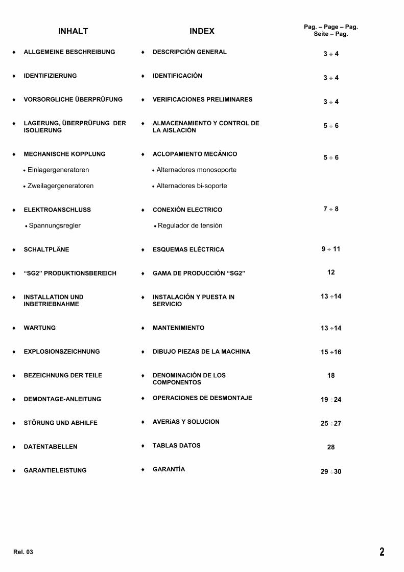
INHALT
ALLGEMEINE BESCHREIBUNG
IDENTIFIZIERUNG
VORSORGLICHE ÜBERPRÜFUNG
LAGERUNG, ÜBERPRÜFUNG DERISOLIERUNG
MECHANISCHE KOPPLUNG
Einlagergeneratoren
Zweilagergeneratoren
ELEKTROANSCHLUSS
Spannungsregler
SCHALTPLÄNE
“SG2” PRODUKTIONSBEREICH
INSTALLATION UNDINBETRIEBNAHME
WARTUNG
EXPLOSIONSZEICHNUNG
BEZEICHNUNG DER TEILE
DEMONTAGE-ANLEITUNG
STÖRUNG UND ABHILFE
DATENTABELLEN
GARANTIELEISTUNG
Rel. 03
INDEX
DESCRIPCIÓN GENERAL
IDENTIFICACIÓN
VERIFICACIONES PRELIMINARES
ALMACENAMIENTO Y CONTROL DELA AISLACIÓN
ACLOPAMIENTO MECÁNICO
Alternadores monosoporte
Alternadores bi-soporte
CONEXIÓN ELECTRICO
Regulador de tensión
ESQUEMAS ELÉCTRICA
GAMA DE PRODUCCIÓN “SG2”
INSTALACIÓN Y PUESTA INSERVICIO
MANTENIMIENTO
DIBUJO PIEZAS DE LA MACHINA
DENOMINACIÓN DE LOSCOMPONENTOS
OPERACIONES DE DESMONTAJE
AVERíAS Y SOLUCION
TABLAS DATOS
GARANTÍA
Pag. – Page – Pag.Seite – Pag.
3 4
3 4
3 4
5 6
5 6
7 8
9 11
12
13 14
13 14
15 16
18
19 24
25 27
28
29 30

INTRODUZIONELo scopo delle seguenti istruzioni è diindicare agli utilizzatori le corrette condizionidi impiego degli alternatori serie SG2.
ATTENZIONE!Le istruzioni fornite riportano informazioniatte ad essere utilizzate da personaletecnico qualificato; esse devono essereintegrate dalle leggi e dalle normativevigenti.Le macchine elettriche rotanti presentanoparti pericolose in quanto poste sottotensione ed in rotazione. Pertanto un usoimproprio, la carenza di manutenzione e loscollegamento dei dispositivi di protezionepossono essere causa di gravi danni apersone e cose.
DESCRIZIONE GENERALE.
I generatori della serie SG2 sonoautoregolati, senza spazzole, a 4 poli.Hanno induttore rotante provvisto di gabbiadi smorzamento e indotto fisso a caveinclinate.Gli avvolgimenti sono a passo raccorciatoper ridurre il contenuto armonico.I generatori sono costruiti in conformità alledirettive CEE 89/392, 73/23, 89/336 erelative modifiche, alle norme CEI 2-3, EN60034-1, IEC 34-1, VDE 0530, BS4999-5000, EN 50081-1, EN 50082-1.La carcassa è realizzata in acciaio, gli scudiin ghisa, l’albero in acciaio C45 con ventolacalettata.Il grado di protezione è IP 21 (a richiesta èpossibile realizzare macchine con il grado diprotezione superiore).Gli isolamenti sono eseguiti in classe H.La conformità alle norme sopra citate fa sìche gli alternatori della serie SG2 nonpresentino pericolo per l’operatore seinstallati, usati e mantenuti secondo leistruzioni fornite da NSM, e a condizione chei dispositivi di sicurezza siano tenuti inperfetta efficienza.Per questa ragione occorre attenersiscrupolosamente alle istruzioni riportate inquesto manuale.
IDENTIFICAZIONE
La targhetta di identificazione è fornitaassieme al manuale di istruzioni, e deveessere applicata esternamenteall’alternatore.Per qualsiasi comunicazione con NSM o coni centri di assistenza autorizzati, riferiresempre tipo, potenza e n° di matricoladell’alternatore in oggetto.
VERIFICHE PRELIMINARI
Al momento della ricezione dell’alternatore siraccomanda di verificare che non abbiasubito danni durante il trasporto.
INTRODUCTIONThe purpose of the following instructions is toexplain to the operators the proper use of theSG2 series of NSM alternators.
WARNING!The instructions given provide informationto be used by qualified technicians; theinformation must be integrated with theapplicable laws and regulations in force.Some parts of rotating electrical machinesare hazardous, as they are live and rotate.Therefore, improper use of the same,failure to carry out maintenance and theremoval of the safety devices may lead toserious personal injury or damage toproperty.
GENERAL DESCRIPTION
The SG2 series of generators are self-regulating, brushless, with 4 poles.They have a rotating inductor provided with adamping cage and a main stator with skewedslots. The windings have a shortened pitch toreduce the harmonic content.The generators are built in compliance withEEC directives 89/392, 73/23, 89/336 andrelevant amendments and in accordance withstandards CEI 2-3, EN 60034-1, IEC 34-1,VDE 0530, BS4999-5000, EN 50081-1, EN50082-1.The frame is made of steel, the flanges incast iron, the shaft in steel C45 with splinedfan.The degree of protection is IP 21 (on request,it is possible to supply machines with thehigher levels of protection degree ).The insulation provided is class H.Compliance with the above-mentionedstandards means that the SG2 series ofgenerators does not present any danger forthe operator if they are installed, used andmaintained in accordance with theinstructions provided by NSM and oncondition that the safety devices are kept inperfect working order.For this reason, it is necessary to adherestrictly to the instructions given in thismanual.
IDENTIFICATION
The identification plate is supplied togetherwith the instruction manual and must be fittedon the outside of the generator.When contacting NSM or the authorizedassistance centres, details must always begiven of the type, power and serial number ofthe alternator in question.
PRELIMINARY CHECKS
When the alternator is delivered, make surethat it has not been damaged duringtransportation.
INTRODUCTIONL’objectif des instructions suivantes estd’indiquer aux utilisateurs les correctesconditions d’emploi des alternateurs NSMsérie SG2.
ATTENTION !Les instructions fournies reportent desinformations qui doivent être utilisées pardu personnel technique qualifié; ellesdevront être completèes par lesdispositions de la loi ou par les normestechniques en vigueur.Les machines électriques rotativesprésentent des parties dangereusesplacées sous tension et en rotation. Parconséquent un usage impropre, unentretien insuffisant et le débranchementdes dispositifs de sécurité et de protectionpeuvent être la cause de gravesdommages aux personnes et aux choses.
DESCRIPTION GENERALE
Les générateurs de la série SG2 sontautorégulés, sans balais, à 4 pôles.Ils sont équipés d’un inducteur rotatif aveccage d’amortissement et stators à encochesinclinées.Les bobinages sont à pas raccourcis pourdiminuer le taux d’harmoniques.Les générateurs sont construitsconformément aux directives CEE 89/392,73/23, 89/336 et relatives modifications, auxnormes CEI 2-3, EN 60034-1, IEC 34-1, VDE0530, BS4999-5000, EN50081-1, EN50082-1La carcasse est réalisée en acier, lesflasques en fonte, l’arbre en acier C45 avecventilateur claveté.Le grade de protection est IP 21 (il estpossible de réaliser sur demande desmachines avec le niveau de protectionsupérieur).Les isolements sont effectués en classe H.La conformité aux normes ci-dessusindiquées, permet d’obtenir des alternateursde la série SG2 qui ne présentent pas dedanger pour l’opérateur, s’ils sont installés,employés et entretenus selon les instructionsfournies par NSM, et à condition que lesdispositifs de sécurité soient tenus enparfaite condition de fonctionnement.Il est pour cette raison indispensable derespecter scrupuleusement les instructionsreportées dans ce manuel.
IDENTIFICATION
La plaque d’identification est fournie avec lemanuel d’instructions et devra être appliquéeextérieurement sur l’alternateur.Pour toute communication avec NSM ou lescentres d’assistance agréés, indiquertoujours le type, la puissance et le nr. dematricule de l’alternateur en objet.
CONTROLES PRELIMINAIRES
Au moment de la réception de l’alternateur, ilest recommandé de vérifier qu’il n’a pas étéendommagé pendant le transport.

EINLEITUNGZiel der folgenden Anweisungen ist es, denAnwendern korrekte Einsatzbedingungen fürdie Generatoren NSM der Serie SG2aufzuzeigen.
ACHTUNG!Die Anleitung enthält Informationen fürqualifizierte Fachtechniker und mussdurch die einschlägige Gesetzgebung unddie geltenden Richtlinien integriertwerden.An elektrischen, umlaufenden Maschinensind Bauteile vorhanden, die dadurch,dass sie unter Spannung stehen unddrehen, eine Gefahr darstellen. Daherkönnen unsachgemäßer Gebrauch,mangelhafte Wartung und dasAbklemmen der Sicherheitseinrichtungenzu schweren Personen- und Sachschädenführen.
ALLGEMEINE BESCHREIBUNG
Bei den Generatoren der Serie SG2 handeltes sich um selbstregelnde, bürstenlose, 4-polige Generatoren.Sie sind mit Drehinduktor mitDämpfungskäfig und festem Anker mitschrägen Nuten ausgestattet.Die Wicklungen wurden mit verkürztemSchritt ausgeführt, um den Oberwellengehaltzu reduzieren.Die Generatoren entsprechen den EWG-Richtlinien 89/392, 73/23 und 89/336 sowiederen entsprechenden Änderungen und denRichtlinien CEI 2-3, EN 60034-1, IEC 34-1,VDE 0530, BS4999-5000, EN 50081-1 undEN 50082-1.Das Gehäuse besteht aus Stahl, dieLagerschilde sind aus Guss und die Welleaus Stahl C45 mit aufgezogenem Lüfterrad.Schutzklasse: IP 21 (auf Anfrage sind auchMaschinen mit höheren Schutzklasseerhältlich).Die Isolierungen werden in der Klasse Hausgeführt.Da die Generatoren der Serie SG2 den obengenannten Richtlinien entsprechen, stellensie keine Gefahr für den Bediener dar, wennsie unter Einhaltung der von der Fa. NSMgegebenen Anweisungen eingebaut,verwendet und instandgehalten werden. Ausdiesem Grund ist es unbedingt erforderlich,sich genau an die in dieser Anleitunggegebenen Anweisungen zu halten.
IDENTIFIZIERUNG
Das Typenschild liegt derBedienungsanleitung bei und muss außenam Generator angebracht werden. Bei jederMitteilung an bzw. Kontakt mit der Fa. NSModer den autorisierten Kundendienstzentrensind immer Typ, Leistung und Seriennummerdes betreffenden Generators anzugeben.
VORSORGLICHE ÜBERPRÜFUNG
Bei Erhalt des Generators sollte dieserumgehend auf Transportschäden hinüberprüft werden.
INTRODUCIÓNEl presente manual de instrucciones tiene lafinalidad de indicar al usuario las correctascondiciones de empleo de los alternadoresNSM serie SG2.
¡ATENCION!Las instrucciones suministradas contienendatos que deberán ser utilizadosexclusivamente por personal técnicocualificado. Dichas instrucciones deberánestar integradas con las actuales leyes ynormativas.Las máquinas eléctricas giratoriascontienen partes peligrosas por serrotantes y estar bajo tensión. Por tanto, unuso inadecuado, la falta de mantenimientoy la desconexión de los dispositivos deprotección pueden ser causa de gravesperjuicios a personas y cosas.
DESCRIPCIÓN GENERAL
Los generadores de la serie SG2 sonautorregulados, sin escobillas ( brushless ) yde 4 polos. Tienen inductor ( giratorio )provisto de jaula de amortiguamiento einducido ( fijo ) con ranuras inclinadas.Los bobinados son de paso acortado parareducir el contenido armónico.Los generadores están fabricados según lasdirectivas CEE 89/392, 73/23, 89/336 y susmodificaciones,y según las normas CEI 2-3,EN 60034-1, IEC 34-1, VDE 0530, BS4999-5000, EN 50081-1, EN 50082-1.La carcasa está realizada en acero, losescudos en fundición y el eje en acero C45con ventilador encajado.El grado de protección es IP 21 (a peticiónse pueden realizar alternadores con ungrado de protección superior).El aislamiento está efectuado en clase H.El respeto de las normas antes citadas haceque los alternadores de la serie SG2 nopresenten peligro para el usuario siempreque se instalen , utilicen y se mantengan deacuerdo con las instrucciones suministradaspor NSM, y siempre que los dispositivos deseguridad se mantengan en perfecto estadode uso. Por esta razón, se deben respetarescrupulosamente las instruccionescontenidas en este manual.
IDENTIFICACIÓN
La tarjeta de identificación se suministrajunto con el manual de instrucciones y sedebe colocar en la parte exterior delalternador.Para realizar cualquier comunicación a NSMo a los centros de asistencia autorizados,siempre se deberá indicar el tipo, potencia yn° de identificación del alternador encuestión .
VERIFICACIONES PRELIMINARES
Cuando se reciba el alternador serecomienda verificar la total ausencia dedaños producidos durante el transporte.
In according to: CEI EN 60034-1 IEC 34.1 VDE 0530 NF 51-111 BS 5000
WEIGHT
60Hz - 1800rppm - PF=0.8
3-PHASE GENERATOR 12 WIRES - 4 POLES
NUOVA SACCARDO MOTORITORREBELVICINO - ITALY
EXCITACION :DATA
Regulator type: AVR620
400
50Hz - 1500rppm - PF=0.8
TYPE
[V][A]
NO LOAD
[A] [V]
kVA
230 200 480
n°
FULL LOAD
[A]
[kg]
[V]
kVA
240277 [V][A]
Protection: IP21 Insulation class: H

IMMAGAZZINAGGIO, CONTROLLOISOLAMENTO
Nel caso l’alternatore non venga postoimmediatamente in servizio, dovrà essereimmagazzinato in luogo coperto, pulito eprivo di umidità.Prima della messa in servizio dopo lunghiperiodi di immagazzinamento, o in presenzadi segni evidenti di umidità o condensa,verificare lo stato di isolamento tra gliavvolgimenti e verso massa.La prova di isolamento deve essereeffettuata da un tecnico qualificato.Prima di eseguire tale prova è necessariosconnettere il regolatore di tensione ed ilponte raddrizzatore.Se le prove forniscono un risultato troppobasso (inferiore ad 1M) è necessarioprovvedere ad asciugare l’alternatore in fornoad una temperatura di 60÷70°C per circa 6ore. Ripetere quindi la prova di isolamento everificare che i risultati forniti siano adeguati.
ACCOPPIAMENTO MECCANICO
Importante!Prima del montaggio pulire le superficid’accoppiamento.Allineare accuratamente il generatore ed ilmotore di trascinamento. Un allineamentoimpreciso può causare vibrazioni edanneggiamento dei cuscinetti.
Alternatori monosupporto (B2-SAE):
I generatori monosupporto vengononormalmente spediti con staffe di fissaggiorotore per il trasporto.Prima dell’installazione rimuovere tali staffe(Fig. 3).Verificare anche tutte le dimensionidel volano e coprivolano del motore primocosì come della flangia e del giunto delgeneratore. Verificare inoltre che lecaratteristiche torsionali del generatore e delmotore siano compatibili.Dopo l’accoppiamento verificare l’esistenzadi un gioco assiale tra il cuscinetto e la suasede di almeno 1,5 - 2mm.Per la coppia di serraggio delle viti chefissano i dischi di accoppiamento al volano,consultare il manuale del motore.
Alternatori bi-supporto (B34):
accoppiamento semi-elastico: si raccomandadi realizzare l’allineamento con cura,verificando che lo scarto di concentricità eparallelismo dei due semi-giunti non siasuperiore a 0.1mm.
accoppiamento tramite cinghie e pulegge:verificare il parallelismo dei due alberi. Latensione delle cinghie non deve essereeccessiva per non compromettere la duratadei cuscinetti. Il carico radiale massimo èindicato in tabella 2 (pag. 28)
STORAGE, CHECKING THE INSULATION
If the alternator is not put into operationimmediately, it must be stored in a covered,clean, damp-free room.Before putting it into operation after longperiods of storage, or in the presence ofobvious signs of damp or condensation,check the condition of the insulation betweenthe windings and towards earth.The insulation must be tested by a qualifiedtechnician.Before carrying out this test, disconnect thevoltage regulator and rotating rectifier.If the tests give an insufficiently low result(below 1MΩ) the alternator must be dried inan oven at a temperature of 60÷70°C forabout 6 hours. The insulation test shouldthen be repeated to check the results areadequate.
MECHANICAL COUPLING
Important!Before assembly clean all connectingsurfaces.Line up the generator and the drive motorwith care. An inaccurate alignment maylead to vibrations and damage thebearings.
Single bearing alternators (B2-SAE):
The single bearing generators are normallydelivered with rotor securing clamps fortransportation.Before installation, remove the clamps(Fig.3). All the measurements of the flywheeland flywheel cover of the drive motor shouldbe checked and of the generator flange andcoupling. Furthermore, ensure that thetorsion characteristics of the generator andthe motor are compatible.Having connected the parts, make sure thatthere is an end play of at least 1,5 – 2mm.between the bearing and its seat.Refer to engine manual for torque wrenchsetting of the screws for fixing the couplingdisc to the flywheel.
Double bearing alternators (B34):
Semi-elastic coupling: the alignment must bemade with care, checking that the differencein concentricity and parallelism of the two halfjoints does not exceed 0.1 mm.
Belt and pulley coupling: check theparallelism of the two shafts. The tension ofthe belts must not be too excessive to avoidcompromising the life of the bearings. Themaximum radial load is shown in the table 2(page 28).
STOCKAGE, CONTROLE DEL’ISOLEMENT
Dans le cas où l’alternateur ne soit pasimmédiatement utilisé et mis en service, ildevra être déposé en magasin dans un lieucouvert, propre et privé d’humidité.Avant la mise en service après une longuepériode de stockage, ou en présence designes évidents d’humidité ou decondensation, vérifier l’état d’isolement entreles bobinages et vers la masse.La vérification de l’état de l’isolement doitêtre effectuée par un technicien qualifié.Avant d’effectuer ce contrôle, il estnécessaire de débrancher le régulateur detension et le pont radresseur.Si les contrôles fournissent un résultat tropfaible (inférieur à 1M), il sera doncnécessaire de sécher l’alternateur en four àune température de 60÷70°C pour environ 6heures. Répéter donc le contrôle de l’état del’isolement et vérifier que les résultatsobtenus correspondent à l’attente.
ACCOUPLEMENT MECANIQUE
Important!Avant le montage nettoyer les surfacesd’accouplement.Aligner soigneusement le générateur et lemoteur d’entraînement. Un alignementimprécis peut causer des vibrations etendommager les roulements.
Alternateurs monopalier (B2-SAE):
Les générateurs monopalier sontnormalement expédiés avec plaquettes defixage rotor pour le transport.Avant l’installation, enlever ces plaquettes(Fig.3). Dans un premier temps, vérifier aussitoutes les dimensions du volan du moteur etsa protection, ainsi que de la bride et desdisques du générateur. Vérifier ensuite, queles caractéristiques de torsion du générateuret du moteur soient compatibles.Après l’accouplement, vérifier l’existenced’un jeu axial entre le roulement sa sièged’au moins 1,5 - 2mm.Pour le couple de serrage des vis de fixationdu disque d’accouplement sur le volantregarder le manuel d’instruction du moteur.
Alternateurs bi-palier (B34):
Accouplement semi-élastique : il est conseilléd’effectuer l’alignement avec soin, envérifiant que l’écart de concentricité et deparallélisme des deux semi-joints ne résultepas supérieur à 0.1mm.
Accouplement par courroies et poulies :vérifier le parallélisme des deux arbres.La tension des courroies ne doit pas êtreexcessive pour ne pas compromettre ladurée de vie des roulements. La chargeradiale maximum est indiquée dans letableau 2 (pag.28).

LAGERUNG UND ÜBERPRÜFUNG DERISOLIERUNG
Sollte der Wechselstromgenerator nichtdirekt in Betrieb genommen werden, ist er aneinem überdachten, trockenen Ort ohneFeuchtigkeit zu lagern.Falls das Gerät erst nach längerer Lagerungin Betrieb genommen wird oder Anzeichenvon Feuchtigkeit oderKondenswasserbildung aufweist, ist derZustand der Isolierung zwischen denWicklungen und zur Masse zu überprüfen.Die Überprüfung der Isolierung hat durcheinen qualifizierten Techniker zu erfolgen.Bevor eine derartige Prüfung durchgeführtwird, muss der Spannungsregler abgeklemmtwerden.Falls das Ergebnis der Prüfung zu niedrig ist(unter 1M), muss der Generator etwa 6Stunden lang bei einer Temperatur von60÷70°C im Ofen getrocknet werden.Anschließend ist die Isolierung erneut zuüberprüfen. Die Ergebnisse müssen dannangemessen sein.
MECHANISCHE KOPPLUNG
Wichtig!Vor dem Zusammenbau sind dieVerbindungsoberflächen zu reinigen.Den Generator und den Antriebsmotorsorgfältig zueinander ausrichten. Eineungenaue Ausrichtung kann zuSchwingungen und Schäden an denLagern führen.
Einlagergeneratoren (B2-SAE):Die Einlagergeneratoren werdennormalerweise mit Befestigungsbügeln fürden Transport geliefert. Vor demZusammenbau sind diese Bügeln zuentfernen (Fig. 3).Es müssen auch alle Abmessungen desSchwungrads und derSchwungradabdeckung am Antriebsmotorsowie des Flanschs und desVerbindungsstücks am Generator überprüftwerden. Darüber hinaus müssen dieTorsionseigenschaften des Generators unddes Motors auf Kompatibilität überprüftwerden. Nachdem die Verbindung ausgeführtwurde, vergewissern Sie sich, dass zwischendem Lager und dessen Aufnahme einAxialspiel von mindestens 1,5 - 2mmvorhanden ist. Für den Anzugskraft derBefestigunsschrauben zwischenkupplungsscheibe und Schwungrad sieheAnleitung des Motors
Zweilagergeneratoren (B34):halbelastische Kopplung: Die Ausrichtung istbesonders sorgfältig durchzuführen.Entsprechend ist zu überprüfen, dass dieAbweichung von der Konzentrizität und derParallelität nicht mehr als 0,1 mm beträgt.
Kopplung über Riemen undRiemenscheiben: Überprüfen Sie dieParallelität der beiden Wellen. DieRiemenspannung darf nicht zu groß sein, umdie Lebensdauer der Lager nicht zubeeinträchtigen. Die maximaleRadialbelastung ist in der Tabelle Nr. 2 (Seite28) angegeben.
ALMACENAMIENTO, CONTROL DELAISLAMIENTO
Si el alternador no se pone inmediatamenteen servicio, se deberá almacenar en lugarcubierto, limpio y sin humedad.Antes de la puesta en servicio, después deprolongados períodos de almacenamiento oante la presencia de signos evidentes dehumedad o de condensación, es necesarioverificar el estado del aislamiento de losbobinados entre si y entre ellos y masa .La prueba de aislamiento la deberá efectuarun técnico cualificado.Antes de realizar dicha prueba es necesariodesconectar el regulador de tensión y elpuente rectificadorSi las pruebas dan un resultado muy bajo(inferior a 1M) será necesario efectuar elsecado del alternador en un horno a unatemperatura de 60÷70°C duranteaproximadamente 6 horas. Después sedeberá repetir la prueba de aislamiento y secontrolará que los resultados obtenidos seancorrectos.
ACOPLAMIENTO MECÁNICO
Importante!Antes del montaje limpiar todas lassuperficies de acoplamiento.Alinear con cuidado el generador y elmotor de arrastre. Una alineaciónimprecisa puede causar vibraciones ydaños a los rodamientos.
Alternadores monosoporte ( B2-SAE )
Los generadores monosoporte normalmentese envían con soportes de fijación para eltransporte.Antes de la instalación hay que retirar dichosoportes (Fig. 3).Verificar también todas las dimensiones delvolante y cubrevolante del motor de arrastrey de la brida y acoplamiento del generador.Además, verificar que las características dearrastre del generador y del motor seancompatibles. Después de efectuar elacoplamiento, verificar que el juego axialentre el rodamiento y su alojamiento sea porlo menos de 1,5 - 2 mm. El par de apriete delos tornillos de fijación del disco deacoplamiento sobre el volante, véase losintrucciones del motor
Alternadores bi-soporte( B 34 ):
acoplamiento semi-elástico: se recomiendaefectuar la alineación con cuidado, verificarque el error de concentricidad y paralelismode los dos semi-acoplamientos no seasuperior a 0,1 mm
acoplamiento mediante correas y poleas:verificar el paralelismo de los dos ejes. Latensión de las correas no debe ser excesivapara no perjudicar la duración de losrodamientos. La carga radial máxima seindica en la tabla 2 (pag.28)
X OKNO

COLLEGAMENTO ELETTRICO
Gli alternatori SG2 sono normalmente dotatidi 12 terminali: (vedi schemi da pag. 9 a 11)Fissare i cavi ai morsetti come consigliatonella Fig. 6Collegamento a terra:Per il collegamento a terra e’ disponibile unmorsetto all’interno della scatola morsetti edun secondo morsetto sul piede delgeneratore. Effettuare la messa a terra conun conduttore di rame di sezione adeguata,secondo le norme vigenti.
REGOLATORE DI TENSIONE (AVR620):Il generatore è provvisto di regolatoreautomatico di tensione AVR620.Il regolatore è dotato di trimmer diregolazione per adattare il suofunzionamento alle diverse condizioni diutilizzo del generatore.In particolare l’AVR620 è dotato di circuitianti-pendolamento adattabili per consentirel’utilizzo di una vasta gamma di carichi. Ilregolatore è dotato inoltre di circuiti interniappositi di protezione, che permettono ilfunzionamento a vuoto a velocità inferiore aquella nominale.E’ sconsigliabile comunque il funzionamentoa carico ad una frequenza (n° giri) inferiore alvalore nominale: questo tipo di serviziorappresenta una condizione di sovraccaricoper tutta la parte di eccitazione delgeneratore.Connessioni del regolatore:l’AVR620 è collegato ai terminali delgeneratore e all’eccitatrice medianteconnettori di tipo Faston.E’ presente un fusibile di protezione da 6.3Adel tipo ad intervento rapido.(Schema a pag. 11)
Trimmer di regolazione:P1 regolazione della tensione di uscita del
generatore; tale trimmer interno consenteuna notevole escursione della tensione(350V480V, 190270, 100140). In casosi voglia ottenere una regolazione piùfine, oppure controllare la tensione adistanza, occorre aggiungere unpotenziometro esterno (22k).
P2 taratura della stabilità; in caso dipendolamenti (fluttuazioni) della tensioneuscita agire su esso, ruotandololeggermente in senso orario.
P3 taratura dello statismo (per applicazioniparticolari); normalmente tutto ruotato insenso anti-orario (statismo zero).
P4 taratura di intervento della protezione perbassa frequenza; normalmente è taratoper ridurre l’eccitazione quando lavelocità di rotazione scende oltre il 10%al di sotto del valore nominale relativo a50Hz. Togliendo il ponticello riportato neldisegno a pag. 11 la regolazione èappropriata per il funzionamento a 60Hz.
In caso di forti sovraccarichi si accenderà ilLED rosso e l’AVR620 limiterà la corrente dieccitazione (e conseguentemente la tensioned’uscita): per ripristinare le normali condizionidi funzionamento spegnere il generatore erimuovere la causa del sovraccarico.
ELECTRICAL CONNECTION
Standard SG2 generators are supplied with12-wire leads: (see diagrams on page 9 11)Fix the output cables as recommendedon Fig. 6Earth connection:For the earth connection a terminal isavailable inside the terminal box and asecond terminal on the foot of the generator.The earth connection should be made usinga copper conductor of a suitable crosssection according to the standards in force.
VOLTAGE REGULATOR (AVR620):The generator is fitted with an automaticvoltage regulator AVR620.The regulator is provided with regulatingtrimmer to adapt its performance to thedifferent generator operating conditions.In particular, AVR620 is provided withadjustable anti-oscillation circuits to allow fora vast range of loads. Furthermore, theregulator is provided with special internalprotection circuits that allow the generator tobe operated no-load at a lower than nominalspeed.However, it is not advisable to operate thegenerator with a load at a frequency (RPM)lower than the nominal value: this type ofoperation represents an overload conditionfor the whole excitation system of thegenerator.Connecting the regulator:AVR620 is connected to the terminals of thegenerator and to the exciter by means offast-on type connectors.A 6.3A safety fuse of the rapid operationtype is provided.(Wiring diagram on page 11)
Regulating trimmer:P1 regulation of the generator output voltage;
this internal trimmer enables aconsiderable deviation in the voltage(350V480V, 190270, 100140). If afiner adjustment is required or the remotevoltage control, an external potentiometer(22k) must be added.
P2 setting the stability; in the event ofoscillations (fluctuations) in the outputvoltage, use the trimmer, turning itslightly clockwise.
P3 setting the static nature (for particularapplications); normally fully turned in ananti-clockwise direction (zero staticnature).
P4 setting the operation of the low frequencyprotection; it is normally set to reduce theexcitation when the speed of rotation fallsbelow 10% of the nominal value relatingto 50Hz. Taking out the jumperconnection as shown in diagram on page11, the regulation is suitable for operationat 60Hz.
In the event of heavy overloads, the red ledwill light up and AVR620 will limit theexcitation current (and consequently theoutput voltage): to reset the usual operatingconditions, switch the generator off andremove the cause of the overload.
CONNEXION ELECTRIQUE
Les alternateurs SG2 sont de série avec 12cables: (voir les connexions a la pag. 9 11)Fixer les cables de sortie comme conseillédans la fig. 6Connexion à terre:Pour la connexion à terre, on a prévu uneborne à l’intérieur de la boîte à bornes et unedeuxième borne sur le pied du générateur.Effectuer la mise à terre avec un conducteuren cuivre de section appropriée, selon lesnormes en vigueur.
RÉGULATEUR DE TENSION (AVR620):Le générateur est équipé d’un régulateurautomatique de tension AVR620.Le régulateur est doté d’un trimmer deréglage pour adapter son fonctionnementaux différentes conditions d’utilisation dugénérateur.En particulier, l’AVR620 a des circuitsd’anti–instabilité pour permettre l’utilisationd’une vaste gamme de charges. Lerégulateur est doté par ailleurs de circuitsinternes conçus pour la protection, quipermettent le fonctionnement à vide à vitesseinférieure à celle nominale.Il est toutefois déconseillé de fairefonctionner à charge à une fréquence (n°tours) inférieure à la valeur nominale : cetype de service représente une condition desurcharge pour toute la partie d’excitation dugénérateur.Connexions du régulateur :l’AVR620 est branché aux terminaux dugénérateur et à l’excitatrice au moyen deconnecteurs du type fast-on.Un fusible de protection de 6.3 A du type àintervention rapide est présent.(Schéma a la page 11)
Trimmer de réglage :P1 réglage de la tension de sortie du
générateur ; ce « trimmer » internepermet une très bonne excursion de latension (de 350V480V, 190V270V,100V140V). Dans le cas où l’onsouhaiterait obtenir un réglage plus fin,ou contrôler la tension à distance, unpotentiomètre extérieur s’avèrenécessaire (22k).
P2 le tarage de la stabilité ; dans le casd’oscillations (fluctuations) de la tensionen sortie, agir sur ce dernier, en le faisantlégèrement pivoter à droite.
P3 le tarage du statisme (pour applicationsparticulières); normalementcomplètement tourné à gauche (statismezéro).
P4 le tarage d’intervention de la protectionpour basse fréquence ; normalement ilest taré pour réduire l’excitation quand lavitesse de rotation descend au dessousde 10% de la valeur nominale relative à50Hz. Enlevant la connection reporté surle schéma a la page 11, le réglage estapproprié au fonctionnement à 60Hz.
Dans le cas de fortes surcharges, le LEDlumineux rouge s’allumera et l’AVR620limitera le courant d’excitation (et donc latension de sortie): pour récupérer lesconditions normales de fonctionnement,arrêter le groupe electrogene et éliminer lacause de la surcharge.

ELEKTROANSCHLUSS
Die Standardgeneratoren SG2 sindnormalerweise mit 12 Leitern ausgestattet:(siehe Schaltpläne auf die Seiten 9 11)Die Befestigung der Leistungskabeln ist wieim Bild 6 zu empfehlen.Erdung:Für die Erdung ist die im Klemmenkastenuntergebrachte Klemme sowie eine zweiteKlemme am Fuß des Generators zuverwenden. Verwenden Sie für die Erdunggemäß den geltenden Vorschriften einenKupferleiter mit entsprechendem Querschnitt.
SPANNUNGSREGLER (AVR620):Der Generator ist mit einemSpannungsregler AVR620 ausgestattet.Der Regler ist mit Potentiometerausgestattet, damit er den unterschiedlichenEinsatzbedingungen des Generatorsangepasst werden kann.Im Einzelnen ist der AVR620 mitanpassbaren Stabilitätsregelkreis versehen,so dass das Gerät für eine breite Lastpaletteverwendet werden kann. Der Regler verfügtaußerdem über innenliegendeSchutzeinrichtung, so dass er beim Leerlaufeinen Betrieb mit niedriger Drehzahl,ermöglicht.Beim Betrieb unter Last sollte in jedem Falleine Frequenz (Drehzahl) unter demNennwert vermieden werden, denn dieseBetriebsart stellt eine Überlastung desGenerator-Erregersystem dar.Anschlüsse des Spannungsreglers:Der AVR620 ist durchSchnellanschlußverbindern an die Klemmendes Generators und des Erregersystemsangeschlossen. Außerdem ist eine schnelleingreifende Schmelzsicherung (6.3A)vorhanden. (Schaltschema an Seite 11)Einstellungspotentiometer :P1 Einstellung der Lieferspannung des
Generators; dieser interne Potentiometerermöglicht eine beträchtlicheSpannungsausschlagweite (350V480V,190270, 100140). Sollte eine genauereEinstellung erforderlich sein oder dieSpannung ferngeregelt werden, musszusätzlich ein externes Potentiometer(22k) installiert werden.
P2 Abgleichung der Stabilität; beiSpannungspendelung (Schwankungen)leicht daran rechts drehen.
P3 Abgleichung der Statik (für besondereAnwendungen); Standardeinstellung ganzlinks (d.h. Statik null).
P4 Abgleichung des Unterdrehzahlschutzes;die Standardeinstellung derart, dass dieErregung reduziert wird, wenn dieDrehzahl um mehr als 10% unter denrelativen Nennwert von 50Hz absinkt.Wenn die in der Zeichnung (Seite 11)abgebildete Brücke entfernt wird, ist dieEinstellung für den Betrieb bei 60Hzangemessen.
Bei starker Überlastung leuchtet das roteLED auf und der AVR620 begrenzt denErregungsstrom und damit dieLieferspannung. Zur Rückstellung dernormalen Betriebsbedingungen schalten Sieden Generator ab und beseitigen dieUrsache für die Überlastung.
CONEXIÓN ELECTRICO
Los generadores SG2 se suministran con 12terminales:(véanse los esquemas de la página 9 11)Conecte los cables de salida, como se indicaen la Fig. 6Conexión a tierra:Para efectuar la conexión a tierra hay unborne disponible dentro de la caja de bornesy otro borne en la base del generador.Realizar la conexión a tierra con unconductor de cobre de sección adecuada,de acuerdo con las normas vigentes.
REGULADOR DE TENSIÓN:El generador está provisto de un reguladorautomático de tensión AVR620.El regulador está dotado de un trimmer deregulación para adaptar su funcionamiento alas distintas condiciones de utilización delgenerador.En particular el AVR620 está dotado decircuitos de anti-oscilamiento adaptablespara permitir la utilización de una vasta gamade cargas. Además, el regulador está dotadode circuitos internos de protección quepermiten el funcionamiento en vacío convelocidad inferior a la nominal.De todos modos se desaconseja elfuncionamiento con carga a una frecuencia(n° de vueltas) inferior al valor nominal: estetipo de servicio representa una situación desobrecarga para toda la parte de excitacióndel generador.Conexiones del regulador:El AVR620 está conectado a los terminalesdel generador y a la excitatriz medianteconectores de tipo faston.Existe un fusible de protección de 6.3 A deltipo de intervención rápida.(Esquemas eléctrica a la pag. 11)Trimmer de regulación:P1 regulación de la tensión de salida del
generador; dicho trimmer interior permiteuna notable variación de la tensión(350V480V, 190270, 100140). Si sedesea obtener una regulación másprecisa o si se desea controlar la tensióna distancia, será necesario agregar unpotenciómetro exterior (22k).
P2 calibración de la estabilidad; en caso defluctuaciones de la tensión de salida, seaconseja intervenir sobre el mismo,girándolo un poco en sentido horario
P3 calibración del estatismo ( caída de rpm )(para aplicaciones particulares);normalmente todo girado en sentidoantihorario ( estatismo cero ).
P4 calibración de intervención de laprotección por baja frecuencia;normalmente está tarado para reducir laexcitación cuando la velocidad derotación desciende más de un 10% pordebajo del valor nominal de 50Hz.Abriendo el puente indicado en el dibujo,la regulación es adecuada para elfuncionamiento a 60Hz.
En caso de grandes sobrecargas, seencenderá la luz(LED) indicadora roja y elAVR620 limitará la corriente de excitación (yconsecuentemente la tensión de salida):para restablecer las condiciones normales defuncionamiento se aconseja apagar elgenerador y eliminar la causa de lasobrecarga.
al caricoto load
Connessione consigliataAdvised connection
al caricoto load
Connessione non consigliataNot advised connection
sensing selection
frequencyselectionremote
trimmer
input
exciter

3 Phase Voltage(L1 - L2 - L3)
50 Hz380÷440V
60 Hz380÷480V
1 Phase Voltage(L1 - N)
50 Hz220÷254V
60 Hz220÷280V
max 40% Power
3 Phase Voltage(L1 - L2 - L3)
50 Hz220÷254V
60 Hz220÷270V
1 Phase Voltage(L1 - L2)
50 Hz220÷254V
60 Hz220÷270V
max 60% Power
1 Phase Voltage(L1 - M)
50 Hz110÷127V
60 Hz110÷135V
max 20% Power
TriangoloDelta
TriangleDreieck
Triángulo
StellaStar
EtoileStern
Estrella

3 Phase Voltage(L1 - L2 - L3)
50 Hz190÷220V
60 Hz190÷240V
1 Phase Voltage(L1 - L2)
50 Hz190÷220V
60 Hz190÷240V
max 60% Power
1 Phase Voltage(L1 - N)
50 Hz110÷135V
60 Hz110÷140V
max 40% Power
1 Phase Voltage(L1 - L2)
50 Hz220÷254V
60 Hz220÷270V
max 60% Power
1 Phase Voltage(L1 - M = L2 -M)
50 Hz110÷127V
60 Hz110÷135V
max 30%+30% Power
Doppia StellaParallel Star
Double EtoileParallel Stern
Estrella en paralelo
Doppio TriangoloDelta Parallel
Double triangleParallel Dreieck
Triángulo en paralelo

SCHEMA DICOLLEGAMENTOPER “AVR 620”
WIRING DIAGRAMFOR “AVR 620”
SCHÉMA DECONNEXION
POUR “AVR 620”
SCHALTPLANFÜR “AVR 620”
CONEXIÓNELÉCTRICA
POR “AVR 620”
Sensing Wires
StatoreStator
AusiliarioAuxiliary
ECCITATRICE - EXCITERRotoreRotor Statore
StatorRotoreRotor

1500rpm - 50 Hz – 400V – PF=0.8 1800rpm - 60 Hz – PF=0.8
kVA % KVA – CL. H %
PesoWeightIn B2Tipo
Type CL. H CL. F 4/4 Y: 440V Y: 480V 4/4 circa - aboutYY: 220V YY: 240V [ kg ]
SG2 180A 20 18.5 82 24 25 84 150
SG2 180B 25 22.5 83 30 31 85 169
SG2 180C 30 28 84.5 34 36 85.5 175
SG2 225-0 40 38 85 46 50 86.4 198
SG2 225A 50 45 86.5 55 60 87.8 250
SG2 225B 65 60 87 75 80 88.4 274
SG2 225C 85 80 89 95 102 90.3 309
SG2 225D 105 100 89.5 120 126 90.8 354
SG2 250E 120 110 90.5 135 145 91.7 404
SG2 250F 135 130 91 150 162 92.3 454
SG2 280A 150 140 90.7 165 180 92 501
SG2 280B 170 160 91 190 205 92.3 531
SG2 280C 190 180 91.2 210 230 92.5 558
SG2 280D 215 200 91.5 240 260 92.7 600
SG2 280E 235 225 91.8 260 285 93.1 665
SG2 280F 270 260 92 300 325 93 751
SG2 280G 350 330 92.5 380 400 93.5 894
INSTALLAZIONE E MESSA IN SERVIZIO
Prima dell’installazione verificare che i dati ditarga del generatore corrispondano allecaratteristiche dell’impianto.
ATTENZIONE! A tensioni d’uscita diverse
corrispondono potenze e correntidiverse: utilizzare cavi di sezioneadeguata.
Si consiglia di montare l’interruttore diprotezione in prossimità delgeneratore.
L’alternatore dovrà essere installato inun locale sufficientemente ampio, conpossibilità di scambio d’ariadirettamente con l’atmosfera.
E’ indispensabile che le aperture diaspirazione e di scarico dell’aria nonsiano ostruite e che il posizionamentosia tale da evitare l’aspirazionedell’aria calda prodotta dal motoreprimo.
Prevedere la possibilità di effettuareispezioni e manutenzioni.
Prima del primo avviamento occorreverificare: che tutti i collegamenti elettrici siano
eseguiti correttamente. che tutti i dadi dei morsetti siano ben
serrati. che l’impianto sia dotato di opportune
protezioni che le griglie di protezione siano montate
MANUTENZIONE
Attenzione! Prima di eseguire qualsiasi tipodi manutenzione o riparazione, assicurarsiche il gruppo non possa autoavviarsi tramiteappositi quadri di comando.
Verificare periodicamente:1) il serraggio di tutti i dadi di fissaggio
compresi i dadi delle morsettiere che, seallentati possono provocare notevolisurriscaldamenti nei cavi
2) che non ci siano rumori anomali ovibrazioni eccessive
3) che le griglie di passaggio dell’aria sia iningresso che in uscita siano sempre benpulite
4) che i gommini elastici dei giunti diaccoppiamento tipo B34 non siano usurati
I cuscinetti non necessitano di alcunamanutenzione poiché sono lubrificati a vita(circa 20000 ore in condizioni di normaleimpiego): si consiglia la sostituzione solo incorrispondenza di revisione completa delgruppo (dopo 20000 ore di funzionamento)o in seguito a rumori anomali.
Attenzione! In caso di pulizia del gruppo nonutilizzare acqua o solventi in quantitàeccessiva e comunque evitare il contatto fraquesti e gli avvolgimenti onde evitare il lorodanneggiamento
INSTALLATION AND START-UP
Before installation, check that the details onthe generator rating plate correspond withthe characteristics of the system.
WARNING! Different output voltages correspond
to different powers and currents: usecables of an adequate cross section.
We recommend to assemble thecircuit-breaker of protection near thealternator.
The alternator should be installed in asufficiently large room with thepossibility of changing the air directlyfrom the atmosphere.
It is essential for the inlet and outletair-grating not to be obstructed andthe inlet of hot air produced by thedrive engine should be avoided.
Provision should be made for inspectionsand maintenance to be carried out duringoperation life.
Before first starting up, check: if all electrical connections are correctly
performed. if all bolts of terminals are properly
tightened that the plan is provided with the correct
protection devices that protection-screens are assembled
MAINTENANCE
Warning! Before performing any type ofmaintenance or repair, make sure that theunit cannot be accidentally restarted fromthe control panels.
Regularly check the following:1) the tightening of all the fixing nuts,
including the nuts on the terminal boardsthat can create serious cable overheating ifloose;
2) that there are no unusual noises orexcessive vibrations;
3) that the air passage vents at both the inletsand outlets are always clean and free fromobstruction;
4) that the elastic washers on the B34-typecoupling joints are not worn-out.
The bearings require no maintenancebecause they have been provided withlifelong lubrication (and last approximately20,000 hours under normal workingconditions): we recommend replacing thebearings only whenever the unit iscompletely overhauled (after 20,000working hours) or whenever unusualnoises are heard.
Warning! Never use excessive quantities ofsolvents or water when cleaning the unit, andprotect the windings from contact with thesesubstances in order to prevent damage.
INSTALLATION ET MISE EN SERVICE
Avant l’installation, vérifier que les donnéesde la plaque du générateur correspondentaux caractéristiques de l’installation.
ATTENTION! Aux tensions de sortie différentes,
correspondent des puissances etcourants différents: utiliser des câblesde section appropriée.
Si conseillé l’installation del’interrupteur de protection près del’alternateur.
L’alternateur devra être installé dansun local suffisamment vaste, équipéde systèmes de recyclage d’airdirectement avec l’atmosphère.
Il est indispensable que les ouverturesd’aspiration et d’évacuation de l’air nesoient pas bouchées et que leurpositionnement soit tel, quel’aspiration de l’air chaud produit parle moteur d’entraînement soit évitée.
Prévoir la possibilité d’effectuer desinspections et entretiens.
Avant le premier démarrage, vérifier: que toutes les connexions electrique
soient correctement exécutées que toutes les bornes soient bien serrées que l’installation soit dotée des
protections opportunes que les grilles de protection soient
montées
MAINTENANCE
Attention! Avant d'exécuter toutemaintenance ou réparation, assurez-vousque le groupe ne peut pas démarrerautomatiquement au moyen de tableaux decommande prévus à cet effet.
Vérifiez périodiquement:1) que tous les écrous de verrouillage sont
bien serrés, y compris ceux des bornierscar s'ils étaient mal serrés, cela pourraitprovoquer beaucoup de surchauffe auniveau des câbles;
2) qu'il n'y a ni bruits anormaux ni vibrationsexcessives;
3) que les grilles de circulation de l'air sonttoujours bien propres, aussi bien à l'entréequ'à la sortie;
4) que les caoutchoucs des joints decouplage du type B34 ne sont pas usées.
Les roulements n'ont besoin d'aucunemaintenance car ils sont graissés à vie(environ 20000 heures dans des conditionsd'utilisation normales): nous vousconseillons de les remplacer seulement àl'occasion d'une révision complète dugroupe (au bout de 20000 heures defonctionnement) ou suite à des bruitsanormaux.
Attention! Quand vous nettoyez le groupe,n'utilisez pas de quantités excessives d'eauou de solvants, et évitez de toute manière lecontact entre ces produits et les bobinages,pour éviter de les détériorer.

INSTALLATION UND INBETRIEBNAHME
Vor dem Einbau vergewissern Sie sich, dassdie Daten auf dem Typenschild desGenerators mit den Merkmalen der Anlageübereinstimmen.
ACHTUNG! Unterschiedlichen Spannungen am
Ausgang entsprechenunterschiedliche Leistung und Strom.Verwenden Sie daher Kabel mitangemessenem Querschnitt.
Wird empfohlen den Schutzschalter inder Nähe des Generator anzubauen.
Der Generator muss in einem Raummit ausreichendem Platz installiertwerden, in dem ein direkterLuftaustausch mit der äußerenUmgebung möglich ist.
Den Lufteintritt und Luftaustritt desGenerators darf keinesfalls verstopftsein und die Maschine ist soanzuordnen, dass das Ansaugen vonWarmluft vom Antriebsmotorvermieden wird.
Es muss die Möglichkeit zu Inspektionund Wartungsarbeiten gegeben sein.
Vor dem ersten Anlauf soll folgendesgeprüft werden: dass alle elektrische Anschlüsse korrekt
ausgeführt sind. dass alle die Klemmenbolzen gut
festgezogend sind dass die Anlage mit den notwendigen
Schutzeinrichtungen ausgestattet ist. dass die Schutzgitter befestigt sind
WARTUNG
Achtung! Bevor irgendeine Art von Wartungoder Reparatur durchgeführt wird,vergewissern Sie sich, dass das Aggregatsich nicht selbsttätig über dieentsprechenden Schalttafeln in Betriebsetzen kann.In regelmäßigen Abständen ist Folgendeszu überprüfen:1) der Anzug aller Befestigungsmuttern
einschließlich der Muttern an denKlemmbrettern; falls sie zu locker sind,kann es zu erheblicher Überhitzung derKabel kommen.
2) Es dürfen weder abnormeGeräuschentwicklung noch übermäßigeVibrationen auftreten.
3) Die Lüftungsschlitze der Zu- wie der Abluftmüssen immer sauber sein.
4) Die elastischen Gummis in denKupplungen bei Kupplungsart B34 dürfennicht verschlissen sein.
Die Lager sind wartungsfrei, da sie miteiner Dauerschmierung (etwa 20000Betriebsstunden unter normalenEinsatzbedingungen) versehen sind. Siesollten nur bei kompletter Überholung desAggregats (nach 20000 Betriebsstunden)oder im Falle abnormerGeräuschentwicklung ausgewechseltwerden.
Achtung! Bei der Reinigung keinesfallsübermäßig viel Wasser oder Lösungsmittelverwenden und in jedem Fall den Kontaktzwischen letzteren und den Wicklungenvermeiden, damit diese nicht beschädigtwerden.
INSTALACIÓN Y PUESTA EN SERVICIO
Antes de efectuar la instalación se debeverificar que los datos de la tarjeta delgenerador correspondan a las característicasde la instalación.
ATENCIÓN! A las distintas tensiones de salida les
corresponden potencias eintensidades distintas: utilizar cablesde sección adecuada.
Se recomienda de montar elinterruptor de protección cerca delalternador.
El alternador deberá instalarse en unlocal suficientemente amplio, conposibilidad de intercambio del airedirectamente con la atmósfera.
Es indispensable que las aberturas deaspiración y de salida del aire noestén obstruidas y que suposicionamiento impida la aspiracióndel aire caliente producido por elmotor de arrastre.
Se deberá prever la posibilidad deefectuar inspecciones y mantenimientos.
Antes de arrancar la máquina por primeravez, verifique: si todos los terminales están conectados
correctamente. si todos los bornes están bien apretados si la instalación esta dotada de las
protecciones indispensable si las rejillas protección están colocadas
MANTENIMIENTO
Atención! Antes de efectuar cualquier tipode mantenimiento o reparación, es necesarioasegurarse que el grupo no pueda ponerseen marcha automáticamente mediante losrespectivos cuadros de mando.
Comprobar periódicamente:1) El apriete de todas las tuercas de fijación,
incluyendo las tuercas de la placa debornes , que si se aflojasen podríanocasionar un notable calentamiento delos cables
2) La ausencia de ruidos anómalos o devibraciones excesivas
3) Que las rejillas para el paso del aire tantoen la entrada como en la salida, esténsiempre bien limpias
4) Que las juntas elásticas del acoplamientotipo B 34 no estén gastadas
Los rodamientos no necesitan ningúnmantenimiento porque están lubricados depor vida (aproximadamente 20000 horasen condiciones normales de uso). Serecomienda su reemplazo sólo cuando seefectúe la revisión completa del grupo(después de 20000 horas defuncionamiento) o si se detectan ruidosanómalos.
Atención! Si se necesita limpiar el grupo, nose debe utilizar agua o disolventes enexceso; de todos modos, se debe evitar elcontacto entre éstos y los bobinados paraque no se deterioren.

SG2 280
SUR
GE
SUPP
RESS
OR
33 36 30
36
32
37
3432
36
37
32
37
38
3931
23
1924
2220
21
2929a
29
10
5a
5
40
24a
1
1412
35
18a
17
8
8a
4
116
7
18
DISCO DIODI - ROTATING RECTIFIERDISQUE RADRESSEUR - DIODENSCHEIBE
DISCO RECTIFICADOR
DISEGNO ESPLOSO - EXPLODED DIAGRAM
25
15
28
26
27 18b
10
6312-2Z
Rotating Rectifier - Cod. KCPDRSG1Diode reverse polarity - Cod. KDP70A08RFDiode forward polarity - Cod. KDP70A08F
AVR-Fuse: 6.3A - Cod. KAF520F6A3Type: AVR620 - Cod. KVR620
7MTP0610SG2 - 225
ERSATZTEILE - PIEZAS DE RECAMBIOPARTI DI RICAMBIO - SPARE PARTS - PIECES DE RECHANGES
37
12
1028
6310-2Z6311-2Z 6313-2Z
5
365a
REF. NR.4 7MTP06082
SG2 - 180
6317-2Z6314-2Z
-
SG2- 2807MTP0612SG2 - 250
-
29b
46
44
43
43
SG2 280 SG2 180250
28
15
26
7
16
16
27
18b
18b
B34 - SG2 225
25
45
42
3a
7MTP06161
11
8
8a
44
43
43
42
44
3a
5b
B2 - SAE B 34In caso di richiesta ricambi indicare sempre il tipo, potenza e N° di matricola dell’alternatore.
In case of spare parts inquiry, details must always be given of type, power and serial number of the alternator.Pour demande de pièces de rechanges indiquer le type, la puissance et le nr. de matricule de l’alternateur.Falls Ersatzteile-Anfrage sind Typ, Leistung und Serienummer des betreffenden Generators anzugeben.
En caso de pedido de piezas de recambio, se deberá indicar el tipo, potencia y n° de identificación del alternador.
NOMENCLATURADELLE PARTI
PART NAME NOMENCLATURE BEZEICHNUNG DERTEILE
DENOMINACIÓN DELOS COMPONENTES
1) Carcassa con statoreprincipale.
2) Rotore principale3) Coperchio morsettiera3a) Viti di fissaggio4) Morsettiere5) Reg. di tensione (AVR)5a) Fusibile (AVR) 6.3A5b) Antivibrante (AVR)6) Viti scudo posteriore7) Coperchio posteriore8) Statore eccitatrice8a) Viti di fissaggio9) Rotore eccitatrice10) Disco diodi11) Scudo lato posteriore12) Cuscinetto lato
posteriore14) Anello “Seeger”
posteriore15) Anello “Seeger” lato
accoppiamento16) Viti di fissaggio17) Morsetto di terra18) Rete protezione uscita
aria (B2-SAE)18a) Rete prot. inferiore18b) Rete protezione uscita
aria (B34)19) Viti di fissaggio20) Dischi spessore21) Mozzo portadischi22) Dischi accoppiamento23) Ventola24) Flangia (B2-SAE)24a) Viti di fissaggio25) Scudo L. A. (B34)26) Disco bloccaggio
cuscinetto27) Viti di fissaggio28) Cuscinetto L. A. (B34)29) Linguetta albero29a) Linguetta bloccaggio ventola29b) Anello “Seeger”30) Connessione (+) rotore
principale31) Connessioni diodi32) Connessioni rotore
eccitatrice33) Disco porta-diodi34) Connessione (-) rotore
principale35) Dado di fisssaggio
ponte diodi36) Diodo diretto37) Diodo inverso38) Filtro antidisturbo39) Dissipatore40) Staffa porta morsettiere42) Coperchio scatola
morsetti43) Pannello laterale44) Pannello frontale45) Pannello posteriore
SG2-28046) Coperchio accesso
AVR
1) Frame with main stator2) Main rotor3) Terminal-cover3a) Fixing screws4) Terminal blocks5) Voltage regulator (AVR)5a) Fuse (AVR) 6.3A5b) Shock absorber (AVR)6) Fixing screws7) Rear cover8) Exciting stator8a) Fixing screws9) Exciting rotor10) Rotating rectifier11) N.D.E. endshield12) N.D.E. bearing14) Snap ring N.D.E. side15) Snap ring D.E. side16) Fixing screws17) Earth terminal18) Air outlet protection-
screen (B2-SAE)18a) Protection-screen18b) Air outlet protection- screen (B34)19) Fixing screws20) Shimming plates21) Coupling hub22) Coupling-plates23) Fan24) Coupling-flange
(B2-SAE)24a) Fixing screws25) D.E. endshield (B34)26) Bearing blocking-plate27) Fixing screws28) D.E. Bearing (B34)29) Shaft key29a) Fan locking key29b) Fan locking snap ring30) Connection to main
rotor (+)31) Connection to rotating
diodes32) Connection to exciter
rotor.33) Diodes holder-plate34) Connection to main
rotor (-)35) Rotating rectifier fixing
nut36) Diode forward polarity37) Diode reverse polarity38) Surge suppressor39) Heat sink40) Terminal blocks bracket
holder42) Terminal box top cover43) Terminal box side panel44) Terminal box front
panel45) Terminal box rear panel
SG2-28046) AVR access cover
1) Carcasse avec stator2) Ensemble rotor3) Capotage des bornes3a)Vis de fixation4) Planchette à bornes5) Rég. De tension (AVR)5a) Fusible (AVR) 6,3A5b) Antivibrant (AVR)6) Vis de fixation7) Capotage arrière8) Stator de l’excitatrice8a) Vis de fixation9) Rotor de l’excitatrice10) Pont redresseur11) Palier arrière C.O.12) Roulement arrière C.O.14) Anneau “Seeger” C.O.15) Anneau “Seeger” C.A.16) Vis de fixation17) Borne de terre18) Grille de protection (B2-
SAE)18a) Grille de prot. inférieur18b) Grille de prot. (B34)19) Vis de fixation20) Disque de calage21) Manchon
d’accouplement22) Disque d’accouplement23) Turbine24) Bride C. A. (B2-SAE)24a) Vis de fixation25) Palier C. A. (B34)26) Disque qui solidarise le
roulement27) Vis de fixation28) Roulement C. A. (B34)29) Clavette de bout d’arbre29a) Clavette de blocage turbine29b) Anneau “Seeger” de
blocage turbine30) Connexion (+) rotor
principal31) Connexions diodes32) Connexion rotor de
l’excitatrice33) Disque porte diodes34) Connexion (-) rotor
principal35) Ecrou de fixation pont
redresseur36) Diode directe37) Diode inverse38) Filtre39) Radiateur40) Support de les bornes42) Partie superieure du
boite à bornes43) Partie latéral du boite à
bornes44) Partie avant du capotage45) Partie arrier du boite à
bornes SG2-28046) Port d’accès au
régulateur (AVR)
1) Gehäuse mitHauptständer
2) Haupt Rotor3) Klemmenabdeckung3a) Befestigungsschrauben4) Klemmenbrett5) Spannungsregler (AVR)5a) Sicherung (AVR) 6,3A5b) Schwingungsdämpfer(AVR)6) Befestigungsschrauben7) Hintere Abdeckung8) Erreger-Ständer8a) Befestigungsschrauben9) Erreger-Rotor10) Diodenscheibe11) Lagerschild (gegenüber
der Antriebsseite)12) Lager (gegenüber der
Antriebsseite).14) Seegerring (gegenüber
der Antriebsseite)15) Seegerring (A-Seite)16) Befestigungsschrauben17) Erdeanschluss18) Schutzgitter (B2-SAE)18a) Schutzgitter18b) Schutzgitter (B34)19) Befestigungsschrauben20) Beilagescheiben21) Kupplungsnabe22) Kupplungsscheiben23) Lüfterrad24) Kupplungsflansch (B2-
SAE))24a) Befestigungsschrauben25) Lagerschild
Antriebsseite (B34)26) Lageranschlagsscheibe27) Befestigungsschrauben28) Lager Antriebsseite29) Wellenpassfeder29a) Sperrungsfeder des
Lüfterrads29b) Seegerring des
Lüfterrads30) Hauptrotoranschluss (+)31) Diodenanschlüsse32) Erregerrotoranschlüsse33) Diodenhalterung34) Hauptrotoranschluss (-)35) Befestigungsmutter der
Diodenscheibe36) Diode positiv37) Diode negativ38) Entstörer39) Wärmeableiter40) Klemmenbrett-
Tragbügel42) Klemmenkasten-
Abdeckung43) Seitliche Schutzblech
des KLK44) KLK-Stirnbrett45) Hintere Teil des KLK
SG2-28046) Zutritt-Abdeckung des
Spannungsregler (AVR)
1) Caja con Estator2) Rotor3) Tapa de bornes3a) Tornillos de fijación4) Bornes5) Regulador (AVR)5a) Fusible (AVR) 6,3A5b) Antivibrante (AVR)6) Tornillos de fijación7) Tapa posterior8) Estator excitador8a) Tornillos de fijación9) Rotor excitador10) Disco rectificador11) Escudo posterior12) Rodamiento posterior14) Anillo “Seeger”
posterior15) Anillo “Seeger” lato de
acoplamiento16) Tornillos de fijación17) Borne de conexión a
tierra18) Rejilla de protección
(B2-SAE)18a) Rejilla de protección18b) Rejilla de protección (B34)19) Tornillos de fijación20) Discos de spesoramiento21) Cubo portadiscos22) Discos de acoplamiento23) Ventilador24) Brida de acoplamiento
(B2-SAE)24a) Tornillos de fijación25) Escudo lado de
acoplamiento (B34)26) Disco de bloque del
rodamiento27) Tornillos de fijación28) Rodamiento lado de
acoplamiento29) Chaveta29a) Chaveta de bloque del
ventilador29b) Anillo “Seeger” de
bloque del ventilador30) Conexión (+) rotor31) Conexiónes diodos32) Conexiónes rotor
excitador33) Disco portadiodos34) Conexión (-) rotor35) Tuerca de fijación disco
portadiodos36) Diodo directo37) Diodo inverso38) Filtro39) Radiador40) Soporte de los bornes42) Tapa caja de bornes43) Panel lateral caja de
bornes44) Panel anterior caja de
bornes45) Panel posterior caja de
bornes SG2-28046) Tapa de acceso
Regulador AVR

OPERAZIONI DI SMONTAGGIODELL’ALTERNATORE
ATTENZIONE! Prima di eseguirequalsiasi tipo d’intervento, assicurarsi cheil gruppo non possa autoavviarsi tramiteappositi quadri di comando.Tutte le operazioni sotto riportaterichiedono molta attenzione perciò devonoessere eseguite solo da personale tecnicoqualificato: l’inosservanza di quanto scrittopuò essere causa di gravi danniall’alternatore. Eventuali urti ostrisciamenti sugli avvolgimenti possonoprovocare danni irreparabili all’isolamentodegli stessi.
SOSTITUZIONE DEL REGOLATOREAVR 620
1) Scollegare tutti i cavi dal regolatore2) Svitare le quattro viti di fissaggio e
montare il nuovo regolatore3) Effettuare tutti i collegamenti come da
schema di collegamento a pag. 114) Portare l’alternatore alla frequenza
nominale e verificare che le tensioniconcatenate siano corrette:eventualmente ritoccare il valore dellatensione agendo sull’apposito trimmerP1
5) Procedere caricando l’alternatore ericontrollando le tensioni:eventualmente verificare i valori dieccitazione.
SMONTAGGIO DELLO STATOREECCITATRICE (8)
1) In caso di alternatore monosupporto(B2-SAE) disaccoppiato, il rotore deveessere bloccato alla flangia (24) con leapposite staffe (Fig.3, pag.6).
2) Togliere il coperchio posteriore (7)3) Svitare le sei viti (6) di fissaggio scudo
posteriore (11)4) Negli SG2 280 scollegare dal
regolatore i fili rosso e nero collegatiallo statore eccitatrice e tagliare lerispettive fascette di serraggio.
5) Per facilitare l’estrazione dello scudoposteriore, avvitare due viti filettate peralmeno 5 cm, sui due punti di fissaggiodel coperchio posteriore.Importante! Negli SG2 180÷250 loscudo serve solo per il centraggio delcuscinetto ed è separato dallo statoreeccitatrice, mentre per l’altezza d’asse280 lo statore eccitatrice è fissatodirettamente sullo scudo stesso,pertanto l’operazione di estrazione vafatta con particolare cautela.
6) Per estrarre lo statore eccitatrice,svitare le 4 viti (8a) di fissaggio
7) Estrarlo manualmente oeventualmente con l’ausilio di unapposito estrattore
8) Per il rimontaggio effettuare leoperazioni inverse.
ALTERNATOR DISASSEMBLYOPERATIONS
WARNING! Before performing any type ofrepair, make sure that the unit cannot beaccidentally restarted from the controlpanels.All the operations below require carefulattention and must only be performed byqualified personnel. The failure to respectthe indications provided may cause seriousdamage to the alternator. Scratches orimpact to the windings may createirreparable damage to their insulationcapacity.
REPLACEMENT OF THE AVR 620REGULATOR
1) Disconnect all the regulator’s cables.2) Unscrew the four fixing screws and
assemble the new regulator.3) Make all the connections as shown in
the wiring diagram provided on page 114) Rotate the alternator to nominal
frequency and make sure that the linevoltage supplied is correct. If necessary,adjust voltage value by adjusting theappropriate P1 trimmer.
5) Charge the alternator and then check theline voltage again; if necessary checkthe excitation values.
DISASSEMBLY OFEXCITATION STATOR (8)
1) In the case of uncoupled single-bearing(B2-SAE) alternators, the rotor must belocked to the flange (24) with its clamps(Fig.3, page 6)
2) Remove the rear cover (7).3) Unscrew the six screws (6) for the
fastening of the rear end-shield (11).4) For alternators SG2 280, disconnect the
red and black wires connected to theexcitation stator from the regulator andcut the relative clamps.
5) In order to facilitate the removal of therear end-shield, screw in the rear cover’stwo fastening points, two threadedscrews to a distance of at least 5 cm.Important! In SG2 180÷250 models, theend-shield serves only for the centring ofthe bearing and it is separated fromexciter stator, whereas for the frame size280, the exciter stator is assembled onthe end-shield itself, and therefore theremoval operation must be performedwith particular care.
6) In order to remove the exciter statorunscrew the 4 screws (8a)
7) Remove the stator manually or with theuse of the appropriate extractor.
8) Re-assemble everything by performingthe operations above in inverse order.
OPÉRATIONS DE DÉMONTAGE DEL'ALTERNATEUR
ATTENTION! Avant d'exécuter touteinterventions, assurez-vous que le groupe nepeut pas démarrer automatiquement aumoyen de tableaux de commande prévus àcet effet. Toutes les opérations ci-dessousindiquées exigent beaucoup d'attention parconséquent il faut les faire exécuterseulement par du personnel techniquequalifié: l'inobservation de nos indicationspeut causer de graves dommages au niveaude l’alternateur. Des chocs ou des rayureséventuellement provoqués sur les bobinagespeuvent causer des dommages irréparablesau de l'isolation de ces derniers.
REMPLACEMENT DU RÉGULATEUR AVR 620
1) Déconnectez tous les câbles durégulateur.
2) Dévissez les quatre vis de fixation etmontez le nouveau régulateur.
3) Réalisez toutes les connexions commeindiqué sur le schéma de connexion de lapage 11
4) Amenez l’alternateur en rotation etassurez-vous que les trois tensions dansle bornier sont correctes: si besoin est,réajustez la valeur de la tension enagissant sur le trimmer P1.
5) Procédez en chargeant l’alternateur etrevérifiez les tensions au niveau dubornier: si besoin est, vérifiez les valeursd'excitation.
DÉMONTAGE DU STATOR DEL'EXCITATRICE (8)
1) Si l'alternateur monopalier (B2-SAE) estdésaccouplé, le rotor devra être bloqué ala bride d’accouplement (24) avec cesplaquettes (Fig.3, pag.6).
2) Retirez le capot arrière (7).3) Dévissez les six vis (6) qui fixent le palier
arrière (11).4) Sur le modèl SG2 280 déconnectez du
régulateur les fils rouge et noir qui sontconnectés au stator de l'excitatrice etcouper les bandes se serragecorrespondant.
5) Pour faciliter le dégagement de le palierarrière, vissez deux vis filetées sur aumoins 5 cm, sur les deux points defixation du capot arrière. Important! surles modèles SG2 180÷250 le palier nesert qu'à centrer le roulement et il estseparé par le stator de l'excitatrice,tandis-que si la hauter d’axe est 280, lestator de l'excitatrice est fixé directementsur le palier même; et par conséquentl’opération d'extraction doit être exécutéeavec beaucoup de soin.
6) Pour dégager le stator de l'excitatricedévissez les 4 vis (8a).
7) Dégagez-le à la main ou si besoin est, àl'aide de l'extracteur prévu à cet effet.
8) Pour le remontage, faites les mêmesopérations dans le sens inverse.
DEMONTAGE-ANLEITUNG DESGENERATORS
ACHTUNG! Bevor irgendeine Art von Eingriffedurchgeführt wird, vergewissern Sie sich, dassdas Aggregat sich nicht selbsttätig über dieentsprechenden Schalttafeln in Betrieb setzenkann.Alle im Folgenden aufgeführten Arbeitenerfordern größte Aufmerksamkeit und dürfendaher ausschließlich von qualifiziertenTechnikern ausgeführt werden. MangelndeBeachtung der folgenden Angaben kann zuschweren Schäden am Generator führen.Eventuelle Stöße oder Schleifspuren an denWicklungen können irreparable Schäden an derIsolierung derselben nach sich ziehen.
AUSTAUSCH DES REGLERS AVR 620
1) Alle Kabel des Reglers abklemmen.2) Die vier Schrauben lösen und den neuen
Regler einbauen.3) Alle Anschlüsse laut beiliegendem
Schaltplan auf Seite 11 ausführen.4) Den Generator zum Nenndrehzahl bringen
und überprüfen, ob die verkettetenSpannungen korrekt sind. Bei bedarf kannder Wert der Spannung am entsprechendenPotentiometer P1, geändert werden.
5) Den Generator belasten und erneut dieSpannungen überprüfen. Eventuell dieErregungswerte überprüfen.
AUSBAU DES ERREGERSTÄNDERS (8)
1) Bei entkoppelter Einlagerg-Generatoren(B2-SAE), muss den Rotor, durch dieentsprechende Bügeln (Bild 3, Seite 6), andie Kupplungsflansh (24) befestigt werden.
2) Die hintere Abdeckung (7) entfernen.3) Die sechs Schrauben (6) zur Befestigung
des hinteren Lagerschilds (11) lösen.4) Für die Baugröße SG2 280, den roten und
den schwarzen Draht, die mit demErregerständer verbunden sind, vom Reglerabklemmen und die entspechendenSchellen abzuschneiden.
5) Zwei Gewindestifte an den beidenBefestigungspunkten der hinterenAbdeckung mindestens 5 cm weiteinschrauben, um den Lagerschildproblemlos herausziehen zu können.Wichtig! Bei den Modellen SG2 180-250dient der Lagerschild nur zur Zentrierungdes Lagers und es ist vom Erregerständergetrennt, währen bei Baugrößen 280 derErregerständer ist am Lagerschild selbstbefestigt. Daher muss beim Herausziehenbesonders vorsichtig vorgegangen werden.
6) Die 4 Befestigungsschrauben (8a) desErregerständer lösen, um den Selbenherausziehen zu können.
7) Den Stator von Hand oder eventuell mitHilfe des entsprechendenAusziehwerkzeugs herausziehen.
8) Beim Wiedereinbau in umgekehrterReihenfolge vorgehen.
OPERACIONES DE DESMONTAJE DELALTERNADOR
¡ATENCIÓN! Antes de efectuar cualquier tipode mantenimiento o reparación, es necesarioasegurarse que el grupo no pueda ponerse enmarcha automáticamente mediante losrespectivos cuadros de mando.Todas las operaciones abajo indicadasrequieren mucha atención, por tanto deben serrealizadas solamente por personal técnicoespecializado: el incumplimiento de cuanto estáescrito puede originar un grave deterioro delalternador. Eventuales choques o rayados enlos bobinados pueden provocar un dañoirreparable al aislamiento de los mismos.
REEMPLAZO DEL REGULADOR AVR 620
1) Desconectar todos los cables del regulador2) Soltar los cuatro tornillos de fijación y
montar el nuevo regulador3) Efectuar todas las conexiones como se
indica en el esquema de conexión en lapág. 11
4) Hacer girar el alternador a la frecuencianominal y comprobar que las tres tensionesde salida sean correctas: eventualmente,retocar el valor de la tensión interviniendosobre el correspondiente trimmer P1
5) Continuar cargando el alternador y volver acontrolar las tensiones de salida :eventualmente, comprobar los valores deexcitación.
DESMONTAJE DEL ESTATOREXCITATRIZ (8)
1) En el caso de alternador monosoporte (B2-SAE) desacoplado, se deberá fijar el rotor ala brida de acoplamiento (24) con lossoportes (Fig.3, pag.6)
2) Quitar la tapa posterior (7)3) Soltar los seis tornillos (6) que fijan el
escudo posterior (11)4) En el modelo SG2 280, desconectar del
regulador los cables rojo y negro que estánconectados al estator excitatriz y cortar lasrispectivas fajitas de bloque cables.
5) Para facilitar la extracción del escudoposterior, atornillar por lo menos 5 cm dostornillos, en dos puntos de fijación de latapa posterior. ¡Importante! En el modeloSG2 180÷250 el escudo sólo sirve para elcentrado del rodamiento y es separado delestator excitatriz, mientras la altura de eje280, el estator excitatriz es fijado en elmismo escudo; por tanto, la operación deextracción se debe realizar con muchacautela.
6) Para extraer el estator excitatriz soltar los 4tornillos (8A) de fijación.
7) Extraerlo manualmente o eventualmente,mediante la ayuda del adecuado extractor
8) Para volver a efectuar el montaje, efectuarlas operaciones inversas.
SMONTAGGIO E SOSTITUZIONE DELDISCO DIODI E DEI DIODI
1) In caso di alternatore monosupporto(B2-SAE) disaccoppiato, il rotore deveessere bloccato alla flangia (24) con leapposite staffe (Fig.3 pag. 6).
2) Togliere il coperchio posteriore (7)3) Svitare le sei viti (6) di fissaggio scudo
posteriore (11)4) Negli SG2 280 scollegare dal
regolatore i fili rosso e nero collegatiallo statore eccitatrice e tagliare lerispettive fascette di serraggio.
5) Per facilitare l’estrazione dello scudoposteriore, avvitare due viti filettate peralmeno 5 cm, sui due punti di fissaggiodel coperchio posteriore.Importante! Negli SG2 180÷250 loscudo serve solo per il centraggio delcuscinetto ed è separato dallo statoreeccitatrice, mentre per l’altezza d’asse280 lo statore eccitatrice è fissatodirettamente sullo scudo stesso,pertanto l’operazione di estrazione vafatta con particolare cautela.
6) Togliere l’anello seeger (14)7) Estrarre il cuscinetto (12),
possibilmente a caldo, con l’ausiliodell’estrattore: Attenzione! Durantequesta operazione non danneggiare ildisco diodi.
8) Scollegare i cavi di collegamento (32)del rotore eccitatrice e del rotoreprincipale (30, 34)
9) Svitare i tre dadi (35) per separare ildisco diodi dal rotore eccitatrice
10) Sostituire il disco diodi eventualmentesolo i diodi rispettando la polarità.
11) Rimontare il tutto eseguendo leoperazioni inverse, serrandoaccuratamente tutte le viti ecollegando tutti i conduttori nell’esattaposizione.
IMPORTANTE!N.B. 1: In caso di sostituzione dei diodi:verificare che il tipo sia corrispondente erispettare la posizione di montaggioprecedente.N.B. 2: in caso di smontaggio delcuscinetto è consigliabile sostituirlo conuno nuovo. Per facilitare il rimontaggio, ilcuscinetto va scaldato.
SMONTAGGIO DEL ROTORE
1) Disaccoppiare l’alternatore dal motoreprimo
2) Per alternatori con altezza d’assesuperiore a 180 e accoppiamento (B2-SAE) svitare le viti (24a) e togliere laflangia d’accoppiamento (24)
3) Per accoppiamenti bi-supporto B34,svitare le 4 viti (27) del disco difissaggio del cuscinetto latoaccoppiamento e successivamentequelle (24a) di fissaggio dello scudo:quindi sfilare lo scudo (25) con moltacautela.
4) Si consiglia di effettuare le operazionicon l’alternatore in posizione verticale(lato accoppiamento verso l’alto)Per un corretto sollevamento verticaledel rotore, avvitare un golfaresull’albero
DISASSEMBLY AND REPLACEMENT OFDIODES AND ROTATING RECTIFIER
1) In the case of uncoupled single-bearing(B2-SAE) alternators, the rotor must belocked to the flange (24) with the itsclamps (Fig.3, page 6).
2) Remove the rear cover (7).3) Unscrew the six screws (6) for the
fastening of the rear end-shield (11).4) For alternators SG2 280, disconnect the
red and black wires connected to theexcitation stator from the regulator andcut the relative clamps.
5) In order to facilitate the removal of therear end-shield, screw in the rear cover’stwo fastening points, two threadedscrews to a distance of at least 5 cm.Important! In SG2 180÷250 models, theend-shield serves only for the centring ofthe bearing and it is separated fromexciter stator, whereas for the frame size280, the exciter stator is assembled onthe end-shield itself, and therefore theremoval operation must be performedwith particular care.
6) Remove the snap ring (14).7) Remove the bearing (12) (heated, if
possible) by using the extractor.Warning! During this operation, becareful to avoid damaging the rotatingrectifier.
8) Disconnect the excitation rotor and themain rotor connection cables (32, 30, 34)
9) Unscrew the three nuts (35) to separatethe rotating rectifier from the exciterrotor.
10) Replace the rotating rectifier or thediodes, making absolutely sure torespect polarity.
11) Re-assemble everything by performingthe operations above in inverse order,accurately tightening all the screws andconnecting all the conductors in theirexact positions.
IMPORTANT!Note 1: When replacing the diodes, makesure to use the corresponding type andrespect the previous assembly position.Note 2: When disassembling the bearing,we recommend to replace a new bearing. Inorder to facilitate re-assembly, the bearingshould be heated.
ROTOR DISASSEMBLY
1) Uncouple the alternator from the primemover.
2) For alternators with frame size of higherthan 180 and (B2-SAE) coupling,unscrew the screws (24a) and removethe flange (24).
3) For double-bearing B34 form, firstunscrew the bearing fastening disk’s 4fixing screws (27), on the Drive End sideand then unscrew the end-shield’s fixingscrews (24a). Then remove end-shield(25) carefully.
4) We recommend performing theseoperations with the alternator in verticalposition (with the coupling side facingupwards). Screw an eyebolt into theshaft in order to correctly raise the rotorto the vertical position.
DÉMONTAGE ET REMPLACEMENT DESDIODES ET LE DISQUE REDRESSEUR
1) Si l'alternateur monopalier (B2-SAE) estdésaccouplé, le rotor devra être bloqué ala bride d’accouplement (24) avec cesplaquettes (Fig.3, pag. 6).
2) Retirez le capot arrière (7).3) Dévissez les six vis (6) qui fixent le palier
arrière (11).4) Sur le modèl SG2 280 déconnectez
régulateur les fils rouge et noir qui sontconnectés au stator de l'excitatrice etcouper les bandes se serragecorrespondant.
5) Pour faciliter le dégagement de le palierarrière, vissez deux vis filetées sur aumoins 5 cm, sur les deux points defixation du capot arrière. Important! surles modèles SG2 180÷250 le palier nesert qu'à centrer le roulement et il estseparé par le stator de l'excitatrice,tandis-que si la hauter d’axe est 280, lestator de l'excitatrice est fixé directementsur le palier même; et par conséquentl’opération d'extraction doit être exécutéeavec beaucoup de soin.
6) Retirez l’anneau Seeger (14)7) Dégagez le roulement (12), si possible à
chaud, à l'aide de l'extracteur:Attention! Pendat cette opération ne pasdétériorer le disque redresseur.
8) Déconnectez les câbles de connexion(32) du rotor de l'excitatrice et du rotorprincipal (30, 34)
9) Dévissez les trois ècrou (35) pourséparer le pont redresseur du rotor del'excitatrice.
10) Remplacez le pont redresseur ou lesdiodes en respectant rigoureusement lespolarités.
11) Remontez le tout en exécutant lesopérations précédentes dans le sensinverse, vissez toutes les vis à fond etconnectez tous les conducteurs dans leurposition exacte.
IMPORTANT!N.B. 1: En cas de remplacement des diodes,vérifiez que la diode remplacée et la diodeneuve correspondent et respectez la positionde montage précédente.N.B. 2: si vous démontez le roulement, nousvous conseillons d'en profiter pour leremplacer. Pour faciliter le remontage, il fautchauffer le roulement.
DÉMONTAGE DU ROTOR
1) Désaccouplez l’alternateur du moteurprincipal.
2) En ce qui concerne les alternateurs dontla hauter d’axe est supérieure à 180 etdont l’accouplement est du type (B2-SAE) dévissez les vis (24a) et retirez labride (24).
3) En ce qui concerne les accouplementssbi-support B34, dévissez les 4 vis (27) dudisque de fixation du roulement côtéaccouplement et ensuite celles (24a) quisolidarisent le palier: puis déboîtez lepalier (25) en faisant très attention.
4) Nous vous conseillons de mettrel’alternateur en position verticale (côtéaccouplement vers le haut) pourprocéder aux opérations.Pour lever le rotor verticalement d'unemanière correcte, vissez une oreille delevage sur l'arbre.

AUSBAU UND AUSTAUSCH DERDIODENSCHEIBE UND DER DIODEN
1) Bei entkoppelter Einlagerg-Generatoren(B2-SAE), muss den Rotor, durch dieentsprechende Bügeln (Bild 3, Seite 6), andie Kupplungsflansh (24) befestigt werden.
2) Die hintere Abdeckung (7) entfernen.3) Die sechs Schrauben (6) zur Befestigung
des hinteren Lagerschilds (11) lösen.4) Für die Baugröße SG2 280, den roten und
den schwarzen Draht, die mit demErregerständer verbunden sind, vom Reglerabklemmen und die entspechendenSchellen abzuschneiden.
5) Zwei Gewindestifte an den beidenBefestigungspunkten der hinterenAbdeckung mindestens 5 cm weiteinschrauben, um den Lagerschildproblemlos herausziehen zu können.Wichtig! Bei den Modellen SG2 180-250dient der Lagerschild nur zur Zentrierungdes Lagers und es ist vom Erregerständergetrennt, währen bei Baugrößen 280 derErregerständer ist am Lagerschild selbstbefestigt. Daher muss beim Herausziehenbesonders vorsichtig vorgegangen werden.
6) Den Seegerring (14) zur Befestigung desLagers entfernen.
7) Das Lager (12), möglichst erwärmt, mit Hilfedes Ausziehwergzeugs herausziehen.Achtung! Während diese Arbeitenkeinesfalls die Diodenscheibe (10)beschädigen.
8) Die Anschlüsse (32) vom Erregerrotor undvom Hauptrotor (30, 34) abklemmen.
9) Die drei Befestigungmutter (35) lösen, umdie Diodenscheibe vom Erregerrotor zutrennen.
10) Die Diodenscheibe oder die Diodenauswechseln und dabei genau die Polungbeachten.
11) Alle Teile in umgekehrter Reihenfolgewieder einbauen. Dabei die Schraubensorgfältig anziehen und alle Leiter in derexakten Position anschließen.
WICHTIG!Anm. 1: Bei Austausch der Dioden:Vergewissern Sie sich, den entsprechendenTyp zu verwenden und die vorherigeEinbauposition beizubehalten.Anm. 2: Falls das Lager ausgebaut wird, sollteauch dies gegen ein neues ausgetauschtwerden. Der Wiedereinbau geht leichtervonstatten, wenn das Lager erwärmt wird.
AUSBAU DES ROTORS
12) Den Generator vom Antriebsmotorabkoppeln.
13) Bei Generatoren mit Baugrößen über 200und SAE-Kopplung (B2) den Flansch (24)entfernen.
14) Bei B34-Zweilagergeneratoren die 4Schrauben (27) an der Befestigungsscheibedes Lagers auf der Antriebsseite undanschließend die Befestigungsschrauben(24a) des Lagerschilds lösen. Anschließendden Lagerschild mit äußerster Vorsichtherausziehen.
15) Bei diesen Arbeiten sollte sich derGenerator in senkrechter Stellung(Antriebsseite nach oben) befinden. EineHebeöse an der Welle anschrauben, umden Rotor auf korrekte Art und Weisesenkrecht hochheben zu können.
DESMONTAJE Y REEMPLAZO DEL DISCORECTIFICADOR Y DE LOS DIODOS
1) En el caso de alternador monosoporte (B2-SAE) desacoplado, se deberá fijar el rotor ala brida de acoplamiento con lossoportes (Fig.3, pag.6)
2) Quitar la tapa posterior (7)3) Soltar los seis tornillos (6) que fijan el
escudo posterior (11)4) En el modelo SG2 280, desconectar del
regulador los cables rojo y negro que estánconectados al estator excitatriz y cortar lasrispectivas fajitas de bloque cables.
5) Para facilitar la extracción del escudoposterior, atornillar por lo menos 5 cm dostornillos, en dos puntos de fijación de latapa posterior. ¡Importante! En el modeloSG2 180÷250 el escudo sólo sirve para elcentrado del rodamiento y es separado delestator excitatriz, mientras la altura de eje280, el estator excitatriz es fijado en elmismo escudo; por tanto, la operación deextracción se debe realizar con muchacautela.
6) Quitar el anillo seeger (14) de fijación delrodamiento
7) Extraer el rodamiento (12), a ser posible encaliente, con la ayuda del extractor:¡Atención! evitar el deterioro del discorectificador.
8) Desconectar los cables de conexión delrotor excitatriz (32) y del rotor principal (30,34)
9) Aflojar los tuercas (35) para separar eldisco de diodos del rotor excitatriz
10) Reemplazar el disco de diodos o los diodosrespetando rigurosamente las polaridades
11) Volver a montar todo realizando lasoperaciones inversas, apretando concuidado todos los tornillos y conectandotodos los conductores en su posiciónexacta.
¡IMPORTANTE!N.B. 1: Si es necesario reemplazar los diodos:comprobar el tipo de los diodos y respetar laposición anterior del montaje.N.B. 2: si es necesario desmontar elrodamiento, se recomienda reemplazarlo poruno nuevo. Para facilitar el montaje, esnecesario calentar el rodamiento.
DESMONTAJE DEL ROTOR
1) Desmontar el alternador del motor dearrastre.
2) Para alternadores con una altura de ejesuperior a 200 y acoplamiento SAE(B2) esnecesario quitar la campana (24)
3) Para acoplamientos bisoporte B34, soltarlos 4 tornillos (27) del disco de fijación delrodamiento lado del acoplamiento ydespués soltar los de fijación del escudo(24a): después extraer el escudo conmucha cautela.
4) Se recomienda realizar las operaciones conel alternador en posición vertical (lado delacoplamiento hacia arriba). Para uncorrecto desmontaje vertical del rotor , esnecesario atornillar un enganche en el eje

SMONTAGGIO DEL CUSCINETTO LATOOPPOSTO ALL’ACCOPPIAMENTO
1) In caso di alternatore monosupporto(B2-SAE) disaccoppiato, il rotore deveessere bloccato alla flangia (24) con leapposite staffe (Fig.3, pag.6).
2) Togliere il coperchio posteriore (7)3) Svitare le sei viti (6) di fissaggio scudo
posteriore (11)4) Negli SG2 280 scollegare dal
regolatore i fili rosso e nero collegatiallo statore eccitatrice e tagliare lerispettive fascette di serraggio.
5) Per facilitare l’estrazione dello scudoposteriore, avvitare due viti filettate peralmeno 5 cm, sui due punti di fissaggiodel coperchio posteriore.Importante! Negli SG2 180÷250 loscudo serve solo per il centraggio delcuscinetto ed è separato dallo statoreeccitatrice, mentre per l’altezza d’asse280 lo statore eccitatrice è fissatodirettamente sullo scudo stesso,pertanto l’operazione di estrazione vafatta con particolare cautela.
6) Togliere l’anello seeger (14) difissaggio del cuscinetto
7) Sfilare il cuscinetto (12), possibilmentea caldo, con l’ausilio dell’estrattore:Attenzione! Durante questaoperazione non danneggiare il discodiodi.
8) Sostituire il cuscinetto con unoequivalente (vedi tabella 2 a pag. 28)
9) Rimontare il tutto effettuando leoperazioni inverse.
SMONTAGGIO DEL CUSCINETTO SULLATO DELL’ACCOPPIAMENTO (B 34)
1) Disaccoppiare l’alternatore dal motoree sfilare il giunto di accoppiamentodall’albero
2) Svitare le 4 viti (27) del disco difissaggio del cuscinetto anteriore esuccessivamente quelle (24a) difissaggio dello scudo: quindi sfilare loscudo (25) con molta cautela.
3) Togliere l’anello seeger (15) per ilfissaggio del cuscinetto
4) Sfilare, possibilmente a caldo conl’ausilio dell’estrattore, il cuscinetto(28) e sostituirlo con uno equivalente(vedi tabella cuscinetti 2 a pag. 28)
5) Rimontare il tutto effettuando leoperazioni inverse.
DISASSEMBLY OF THE BEARING FROMTHE SIDE OPPOSITE THE COUPLING
1) In the case of uncoupled single-bearing(B2-SAE) alternators, the rotor must belocked to the flange (24) with its clamps(Fig.3, page 6)
2) Remove the rear cover (7).3) Unscrew the six screws (6) for the
fastening of the rear end-shield (11).4) For alternators SG2 280, disconnect the
red and black wires connected to theexcitation stator from the regulator andcut the relative clamps.
5) In order to facilitate the removal of therear end-shield, screw in the rear cover’stwo fastening points, two threadedscrews to a distance of at least 5 cm.Important! In SG2 180÷250 models, theend-shield serves only for the centring ofthe bearing and it is separated fromexciter stator, whereas for the frame size280, the exciter stator is assembled onthe end-shield itself, and therefore theremoval operation must be performedwith particular care.
6) Remove the bearing’s fixing snap ring(14).
7) Remove the bearing (12) (heated, ifpossible) with the use of the extractor.Warning! During this operation, becareful to avoid damaging the rotatingrectifier.
8) Replace the bearing with one of anequivalent type (consult the bearingtable 2 on page 28).
9) Re-assemble everything by performingthe operations above in inverse order.
DISASSEMBLY OF THE BEARING FROMTHE COUPLING SIDE (B 34).
1) Uncouple the alternator from the motorand remove the coupling joint from theshaft.
2) Unscrew first the front bearing’s fixingdisk’s 4 screws (27) and then theflange’s fixing screws (24a). Thenremove the end-shield (25) carefully.
3) Remove the snap ring (15) used for thefastening of the bearing.
4) Using an extractor if necessary, remove(heated, if possible) the bearing (28) andreplace it with one of an equivalent type(consult the bearing table 2 on page 28).
5) Re-assemble everything by performingthe operations above in inverse order.
DÉMONTAGE DU ROULEMENT DU CÔTÉOPPOSÉ A L’ACCOUPLEMENT
1) Si l'alternateur monopalier (B2-SAE) estdésaccouplé, le rotor devra être bloqué ala bride d’accouplement (24) avec cesplaquettes (Fig.3, pag.6).
2) Retirez le capot arrière (7).3) Dévissez les six vis (6) qui fixent le palier
arrière (11).4) Sur le modèl SG2 280 déconnectez du
régulateur les fils rouge et noir qui sontconnectés au stator de l'excitatrice etcouper les bandes se serragecorrespondant.
5) Pour faciliter le dégagement de le palierarrière, vissez deux vis filetées sur aumoins 5 cm, sur les deux points defixation du capot arrière. Important! surles modèles SG2 180÷250 le palier nesert qu'à centrer le roulement et il estseparé par le stator de l'excitatrice,tandis-que si la hauter d’axe est 280, lestator de l'excitatrice est fixé directementsur le palier même; et par conséquentl’opération d'extraction doit être exécutéeavec beaucoup de soin.
6) Retirez l’anneau Seeger (14) quisolidarise le roulement.
7) Déboîtez le roulement (12), si possible àchaud, à l'aide de l'extracteur:Attention! Pendat cette opération ne pasdétériorer le disque redresseur.
8) Remplacez le roulement par un autresemblable (voir tableau des roulements 2a la page 28).
9) Remontez le tout en exécutant lesmêmes opérations dans le sens inverse.
DÉMONTAGE DU ROULEMENT SUR LECÔTÉ DE L’ACCOUPLEMENT (B 34)
1) Désaccouplez l’alternateur du moteur etdéboîtez le joint d’accouplement del'arbre.
2) Dévissez les 4 vis (27) du disque quisolidarise le roulement avant et ensuitecelles 24a) qui solidarisent le palier: puisdéboîtez le palier (25) en faisant trèsattention.
3) Retirez l’anneau Seeger (15) quisolidarise le roulement.
4) Déboîtez le roulement (28), si possible àchaud, à l'aide de l'extracteur, puisremplacez-le par un autre semblable (voirtableau des roulements 2 a la page 28)
5) Remontez le tout en exécutant lesmêmes opérations dans le sens inverse.

AUSBAU DES LAGERS GEGENÜBER DERANTRIEBSSEITE
1) Bei entkoppelter Einlagerg-Generatoren(B2), muss den Rotor, durch dieentsprechende Bügeln (Bild 3 Seite 6), andie Kupplungsflansh (24) befestigt werden.
2) Die hintere Abdeckung (7) entfernen.3) Die sechs Schrauben (6) zur Befestigung
des hinteren Lagerschilds (11) lösen.4) Für die Baugröße SG2 280, den roten und
den schwarzen Draht, die mit demErregerständer verbunden sind, vom Reglerabklemmen und die entspechendenSchellen zu. Lösen.
5) Zwei Gewindestifte an den beidenBefestigungspunkten der hinterenAbdeckung mindestens 5 cm weiteinschrauben, um den Lagerschildproblemlos herausziehen zu können.Wichtig! Bei den Modellen SG2 180-250dient der Lagerschild nur zur Zentrierungdes Lagers und es ist vom Erregerständergetrennt, währen bei Baugrößen 280 derErregerständer ist am Lagerschild selbstbefestigt. Daher muss beim Herausziehenbesonders vorsichtig vorgegangen werden.
6) Den Seegerring (14) zur Befestigung desLagers entfernen.
7) Das Lager (12), möglichst erwärmt, mit Hilfedes Ausziehwerkzeugs herausziehen.Achtung! Während diese Arbeitenkeinesfalls die Diodenscheibe (10)beschädigen..
8) Das Lager durch ein gleichwertiges Lagerersetzen (siehe entsprechende Tabelle 2auf Seite 28).
9) Alle Teile in umgekehrter Reihenfolgewieder einbauen.
AUSBAU DES LAGERS AUF DERANTRIEBSSEITE (Bauform B 34)
1) Den Generator vom Motor abkoppeln unddie Kupplung aus der Welle herausziehen.
2) Die 4 Schrauben (27) an derBefestigungsscheibe des vorderen Lagersund anschließend dieBefestigungsschrauben (24a) desLagerschilds lösen. Anschließend denLagerschild (25) mit äußerster Vorsichtherausziehen.
3) Den Seegerring (15) zur Befestigung desLagers entfernen.
4) Das Lager (28), möglichst erwärmt, mitHilfe des Ausziehwergzeugs herausziehenund durch ein gleichwertiges Lagerersetzen (siehe entsprechende Tabelle aufSeite 28).
5) Alle Teile in umgekehrter Reihenfolgewieder einbauen.
DESMONTAJE DEL RODAMIENTO - LADOOPUESTO DEL ACOPLAMIENTO
1) En el caso de alternador monosoporte (B2)desacoplado, se deberá fijar el rotor a labrida de acoplamiento con los soportes(Fig.3, pag.6)
2) Quitar la tapa posterior (7)3) Soltar los seis tornillos (6) que fijan el
escudo posterior (11)4) En el modelo SG2 280, desconectar del
regulador los cables rojo y negro que estánconectados al estator excitatriz y cortar lasrispectivas fajitas de bloque cables.
5) Para facilitar la extracción del escudoposterior, atornillar por lo menos 5 cm dostornillos, en dos puntos de fijación de latapa posterior. ¡Importante! En el modeloSG2 180÷250 el escudo sólo sirve para elcentrado del rodamiento y es separado delestator excitatriz, mientras la altura de eje280, el estator excitatriz es fijado en elmismo escudo; por tanto, la operación deextracción se debe realizar con muchacautela.
6) Quitar el anillo seeger (14) de fijación delrodamiento
7) Extraer el rodamiento (12), si es posible encaliente, con la ayuda del extractor.¡Atención! evitar el deterioro del discorectificador.
8) Reemplazar el rodamiento por otroequivalente (véase la tabla de rodamientos2 a la pag. 28)
9) Volver a montar todo efectuando lasoperaciones inversas.
DESMONTAJE DEL RODAMIENTO - LADODEL ACOPLAMIENTO ( B 34)
1) Desmontar el alternador del motor y extraerel acoplamiento elástico del eje.
2) Soltar los 4 tornillos (27) del disco defijación del rodamiento anterior y despuéslos de fijación del escudo (24a): despuésextraer el escudo (25) con mucha cautela.
3) Quitar el anillo seeger (15) de fijación delrodamiento.
4) Extraer, si es posible en caliente, mediantela ayuda del extractor, el rodamiento (28) yreemplazarlo por otro equivalente (véase latabla de rodamientos a la pag. 28)
5) Volver a montar todo efectuando lasoperaciones inversas.

DIFETTO POSSIBILE CAUSA – INTERVENTO (sempre a macchina ferma)
Dopo l’avviamento tensione a vuotoinferiore del 50% della nominale
Verificare che le connessioni dell’AVR siano corrette (pag. 9 11) Controllare il fusibile sull’AVR Diodi rotanti guasti (verificare) Avvolgimenti interrotti o con spire in cortocircuito:
verificare resistenze e la corrente di eccitazione (vedere tab. n. 1 pag. 28) AVR guasto: sostituirlo
Tensione troppo alta o troppo bassa Verificare che le connessioni dell’AVR siano corrette (pag. 9 11) Regolare il trimmer P1 AVR guasto: sostituirlo
Tensione instabile
Verificare l’uniformità della velocità di rotazione Ruotare leggermente il trimmer stabilità P2 in senso orario Verificare lo stato delle connessioni d’uscita Diodi rotanti guasti (verificare) AVR guasto: sostituirlo
Tensione corretta a vuoto,troppo bassa a carico
Ruotare il trimmer statismo P3 in senso antiorario Verificare la velocità di rotazione (possibile sovraccarico del motore primo) Diodi rotanti guasti (verificare)
Caduta di tensione improvvisadurante il normale funzionamento
Sovraccarico o corto circuito Verificare i diodi rotanti e l’AVR: sostituire le parti difettose Avvolgimenti interrotti o con spire in cortocircuito
verificare resistenze e la corrente di eccitazione (vedere tab. n. 1 pag. 28)
Eccessiva temperatura dei cuscinetti(superiore ad 80°C)
Controllare lo stato dei cuscinetti eventualmente sostituirli Anello del cuscinetto non bloccato (ruota nella propria sede) Verificare che il gioco assiale sia di circa 1,5 mm
Temperatura eccessiva dellacarcassa alternatore
Aperture dell’aria parzialmente ostruite o riciclo di aria calda dal motore primo Generatore sovraccaricato: controllare tensione, corrente e frequenza
Vibrazioni eccessive Accoppiamento non corretto: con gioco radiale od allineamento non ben eseguito Caratteristiche torsionali motore-generatore non compatibili. Carico molto squilibrato o sovraccarico
Fumo, scintille o fiamme provenientidall’alternatore
Corto circuito esternamente all’alternatore Corpo estraneo all’interno della macchina Corto circuito nell’avvolgimento statore
ARRESTARE IMMEDIATAMENTE everificare le resistenze
Se necessario, chiamare in nostro servizio assistenza
TROUBLE POSSIBLE CAUSE – REMEDY (always with the machine switched off)
After starting no-load voltagebelow 50% of rated voltage
Check AVR connections (page 9 11) Check fuse on the AVR Rotanting diodes broken (check them) Windings shorted or interrupted:
check windings resistances and exciting current (see Tab. 1, page 28) Faulty AVR: replace it
Too high or too low voltage Check AVR connections (page 9 11) adjust it with the trimmer P1 Faulty AVR: replace it
Unstable Voltage
Check speed uniformity Clockwise fine adjustment of stability trimmer P2 Check output connections Rotanting diodes broken (check them) Faulty AVR: replace it
Correct voltage no-load andtoo low voltage on-load
Ajust drop trimmer P3 anticlockwise Check speed (possible engine overload) Rotanting diodes broken (check them)
Voltage collapses duringnormaly working
Overload or short circuit Check rotanting diodes and AVR: replace the parts demaged Windings shorted or interrupted:
check windings resistances and exciting current (see Tab. 1, page 28)
Excessive overheating of bearings(upper 80°C)
Check condition of bearings: eventually replace them Compensation ring working loose in its housing Check bearing end play (about 1,5 mm)
Excessive overheatingof alternator frame
Air flow (inlet-outlet) partially clogged or hot air is being recycled from engine Alternator is overloaded: check voltage, current and frequency
Excessive vibration Not correct coupling: radial slack or alignment not perfect Torsional performances engine-alternator not compatible Very unbalanced load or overload
Smoke, sparks or flamescoming from alternator
Short circuit in outside circuit Object falled into the machine Short circuit in main stator winding
STOP IMMEDIATELY andcheck resistances
If necessary contact our service
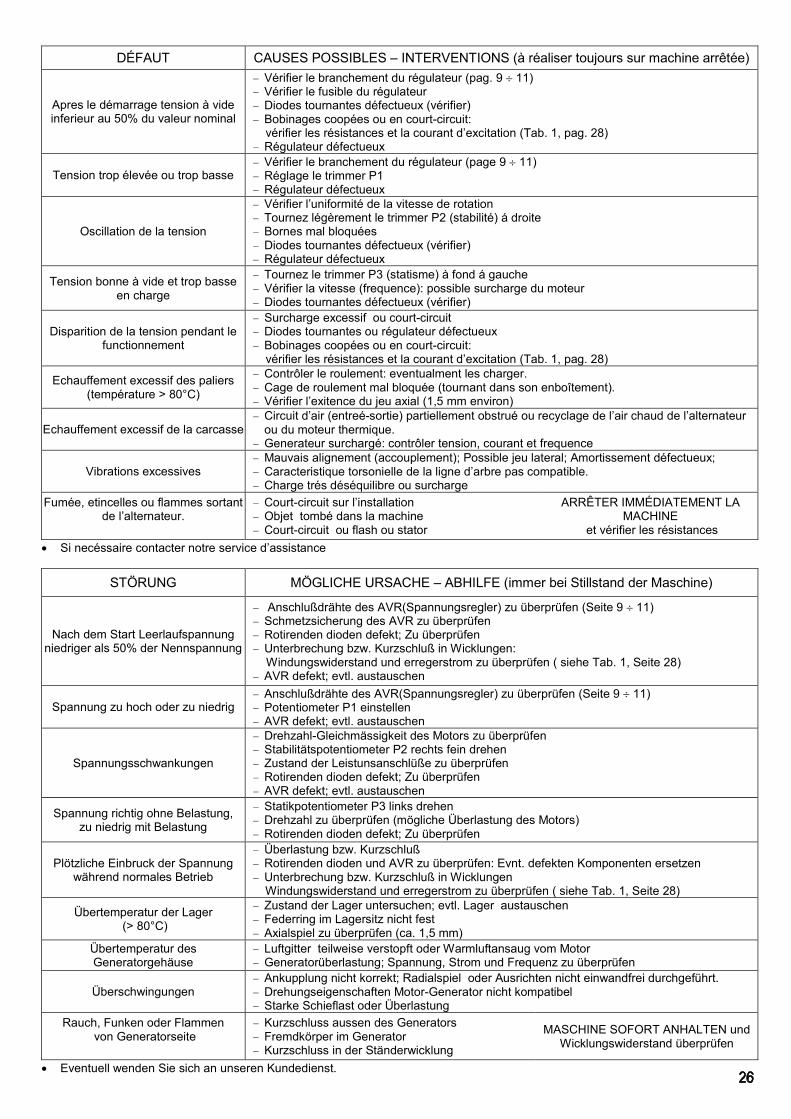
DÉFAUT CAUSES POSSIBLES – INTERVENTIONS (à réaliser toujours sur machine arrêtée)
Apres le démarrage tension à videinferieur au 50% du valeur nominal
Vérifier le branchement du régulateur (pag. 9 11) Vérifier le fusible du régulateur Diodes tournantes défectueux (vérifier) Bobinages coopées ou en court-circuit:
vérifier les résistances et la courant d’excitation (Tab. 1, pag. 28) Régulateur défectueux
Tension trop élevée ou trop basse Vérifier le branchement du régulateur (page 9 11) Réglage le trimmer P1 Régulateur défectueux
Oscillation de la tension
Vérifier l’uniformité de la vitesse de rotation Tournez légèrement le trimmer P2 (stabilité) á droite Bornes mal bloquées Diodes tournantes défectueux (vérifier) Régulateur défectueux
Tension bonne à vide et trop basseen charge
Tournez le trimmer P3 (statisme) à fond á gauche Vérifier la vitesse (frequence): possible surcharge du moteur Diodes tournantes défectueux (vérifier)
Disparition de la tension pendant lefunctionnement
Surcharge excessif ou court-circuit Diodes tournantes ou régulateur défectueux Bobinages coopées ou en court-circuit:
vérifier les résistances et la courant d’excitation (Tab. 1, pag. 28)
Echauffement excessif des paliers(température > 80°C)
Contrôler le roulement: eventualment les charger. Cage de roulement mal bloquée (tournant dans son enboîtement). Vérifier l’exitence du jeu axial (1,5 mm environ)
Echauffement excessif de la carcasse Circuit d’air (entreé-sortie) partiellement obstrué ou recyclage de l’air chaud de l’alternateur
ou du moteur thermique. Generateur surchargé: contrôler tension, courant et frequence
Vibrations excessives Mauvais alignement (accouplement); Possible jeu lateral; Amortissement défectueux; Caracteristique torsonielle de la ligne d’arbre pas compatible. Charge trés déséquilibre ou surcharge
Fumée, etincelles ou flammes sortantde l’alternateur.
Court-circuit sur l’installation Objet tombé dans la machine Court-circuit ou flash ou stator
ARRÊTER IMMÉDIATEMENT LAMACHINE
et vérifier les résistances Si necéssaire contacter notre service d’assistance
STÖRUNG MÖGLICHE URSACHE – ABHILFE (immer bei Stillstand der Maschine)
Nach dem Start Leerlaufspannungniedriger als 50% der Nennspannung
Anschlußdrähte des AVR(Spannungsregler) zu überprüfen (Seite 9 11) Schmetzsicherung des AVR zu überprüfen Rotirenden dioden defekt; Zu überprüfen Unterbrechung bzw. Kurzschluß in Wicklungen: Windungswiderstand und erregerstrom zu überprüfen ( siehe Tab. 1, Seite 28) AVR defekt; evtl. austauschen
Spannung zu hoch oder zu niedrig Anschlußdrähte des AVR(Spannungsregler) zu überprüfen (Seite 9 11) Potentiometer P1 einstellen AVR defekt; evtl. austauschen
Spannungsschwankungen
Drehzahl-Gleichmässigkeit des Motors zu überprüfen Stabilitätspotentiometer P2 rechts fein drehen Zustand der Leistunsanschlüße zu überprüfen Rotirenden dioden defekt; Zu überprüfen AVR defekt; evtl. austauschen
Spannung richtig ohne Belastung,zu niedrig mit Belastung
Statikpotentiometer P3 links drehen Drehzahl zu überprüfen (mögliche Überlastung des Motors) Rotirenden dioden defekt; Zu überprüfen
Plötzliche Einbruck der Spannungwährend normales Betrieb
Überlastung bzw. Kurzschluß Rotirenden dioden und AVR zu überprüfen: Evnt. defekten Komponenten ersetzen Unterbrechung bzw. Kurzschluß in Wicklungen
Windungswiderstand und erregerstrom zu überprüfen ( siehe Tab. 1, Seite 28)
Übertemperatur der Lager (> 80°C)
Zustand der Lager untersuchen; evtl. Lager austauschen Federring im Lagersitz nicht fest Axialspiel zu überprüfen (ca. 1,5 mm)
Übertemperatur desGeneratorgehäuse
Luftgitter teilweise verstopft oder Warmluftansaug vom Motor Generatorüberlastung; Spannung, Strom und Frequenz zu überprüfen
Überschwingungen Ankupplung nicht korrekt; Radialspiel oder Ausrichten nicht einwandfrei durchgeführt. Drehungseigenschaften Motor-Generator nicht kompatibel Starke Schieflast oder Überlastung
Rauch, Funken oder Flammen von Generatorseite
Kurzschluss aussen des Generators Fremdkörper im Generator Kurzschluss in der Ständerwicklung
MASCHINE SOFORT ANHALTEN undWicklungswiderstand überprüfen
Eventuell wenden Sie sich an unseren Kundedienst.

DEFECTO POSIBLE CAUSA-INTERVENCION (actuar siempre con la máquina parada)
Tras arrancar tensión en vacío inferioral 50% de la nominal
- Verificar que las conexiones del AVR sean correctas (pag. 9 11)- Controlar el fusible del AVR- Diodos rotantes averiados (verificar)- Bobinados interrumpido o en cortocircuito:
verificar las resistencias y corriente de exitación (véase la Tab. 1, pag. 28)- AVR averiado : sustituirlo
Tensión demasiado alta- Verificar que las conexiones del AVR sean correctas (pag. 9 11)- Regular el trimmer P1- AVR averiado : sustituirlo
Tensión inestable
- Verificar la uniformidad de la velocidad de rotación- Girar ligeramente el trimmer de estabilidad P2 en sentido horario- Verificar el estado de las conexiones de salida- Diodos rotantes averiados ( verificar )- AVR averiado : sustituirlo
Tensión correcta en vacíodemasiado baja en carga
- Girar el trimmer de estatismo P3 en sentido antihorario- Verificar la velocidad de rotación (posible sobrecarga del motor térmico)- Diodos rotantes averiados (verificar)
Caída de tensión imprevista duranteel funcionamiento normal
- Sobrecarga o cortocircuito- Verificar los diodos rotantes y el AVR : sustituir las partes defectuosas- Bobinados interrumpido o en cortocircuito
verificar las resistencias y corriente de exitación (véase la Tab. 1, pag. 28)Excesiva temperatura de los
rodamientos( superior a 80ºC )
- Controlar el estado de los rodamientos , eventualmente sustituirlos- Anillo del rodamiento no fijado ; ( gira en el alojamiento )- - Verificar que el juego axial sea 1,5 mm aproximadamente
Temperatura excesiva de la carcasadel alternador
- Aberturas del aire parcialmente obstruidas o aspiración del aire caliente del motor térmico- Alternador sobrecargado : controlar tensión, corriente y frequencia
Vibraciones excesivas- Acoplamiento no correcto : con juego radial o alineamiento no bien efectuado- Características torsionales motor-generador no compatibles- Carga muy desequilibrada o sobrecarga
Humo , chispas o llamas provinientesdel alternador
- Cortocircuito externo a la máquina- Cuerpo extraño en el interior de la máquina- Cortocircuito en el bobinado del estator
PARAR INMEDIATAMENTEVerificar las resistencias
Se necesario llamar el nuestro servicio de asistencia

TAB. 2
m3 / min. 1500RPM
m3 / min. 1800RPM
tipotype
cuscinetto posterioreNo Drive End side
cuscinetto anterioreDrive End side
carico radiale maxmax radial load
ventilazioneventilation
ventilazioneventilation
bearing bearingSG 180 6310-2Z 6311-2Z 400 daN 10 12SG 225 6312-2Z 6313-2Z 520 daN 18 21,6SG 250 6312-2Z 6317-2Z - 32 38,4SG 280 6314-2Z - - 38 46
Bearing working life with normal operating condition: about 20000 h
TABELLA CUSCINETTI - BEARINGS DATA SHEET
(solo/only B34)
Durata prevista in condizioni normali di funzionamento: circa 20000h
SG2 180ASG2 180BSG2 180CSG2 225-0SG2 225ASG2 225BSG2 225CSG2 225DSG2 250ESG2 250FSG2 280ASG2 280BSG2 280CSG2 280DSG2 280ESG2 280FSG2 280G
V dc I dc
Full loadcos =0,8
Exc.Stator
Exc.Rotorm
No loadAux(x1-x2)
m
Rotorm
(*) RU1-U2=RV1-V2=RW1-W2=RU5-U6=RV5-V6=RW5-W6
TAB. 1
TypeStatorm
(*)
Resistenza degli avvolgimenti (20°C)Windings resistance (20°C)
Dati di eccitazione (400V 50Hz)Exitation data (400V 50Hz)
V dc I dc
261,0 897 290 6,2 79 4 0,6 20 2,9181,0 871 340 6,2 79 3 0,4 15 2,3137,0 758 380 6,2 79 3 0,5 18 2,5101,0 622 593 5,9 186 7 1,0 27 4,081,0 490 604 5,9 186 5 0,8 27 4,158,0 538 680 5,9 186 5 0,8 27 4,037,0 458 790 5,9 186 5 0,7 24 3,726,0 400 912 5,9 186 6 0,9 24 3,623,0 425 960 6,0 109 4 0,6 22 3,418,0 390 1050 6,0 109 4 0,6 22 3,422,0 530 685 6,2 64 4 0,5 23 3,216,0 450 750 6,2 64 4 0,5 23 3,213,7 420 790 6,2 64 4 0,5 21 3,111,6 400 810 6,2 64 5 0,6 24 3,48,2 370 950 6,6 122 5 0,6 24 3,26,4 355 1077 6,6 122 5 0,6 23 3,04,3 358 1318 6,6 3,0122 6 0,6 23

GARANZIA
La NUOVA SACCARDO MOTORI garantisce labuona costruzione e qualità dei suoi prodotti per12 mesi dalla data di ns. fatturazione.
Durante il suddetto periodo la NSM si impegna ariparare o, a propria discrezione, a sostituire (aproprie spese) nella propria Sede quelle parti chesi fossero avariate, senza altro tipo diresponsabilità diretta o indiretta.
La decisione sul riconoscimento o meno dellagaranzia è riservata esclusivamente alla NSMprevio esame delle parti avariate, che dovrannopervenire in Porto Franco alla sua Sede diTorrebelvicino (VI) Italia; In qualunque caso ilgiudizio della NSM è insindacabile e definitivo.
Ogni reclamo deve contenere la descrizionedella merce, la data fattura, una relazione
completa del difetto riscontrato ed il Numero diSerie della/e macchina/e (vedi targhetta
adesiva).
Tutte le eventuali spese di viaggio, trasferta,trasporto, mano d’opera per lo smontaggio erimontaggio dell’alternatore dall’apparecchiaturaazionante sono sempre a carico dell’utente, anchein caso di verifica per preventivo.
Fanno eccezione le macchine per utilizzocontinuato o per noleggio, per i quali la garanzia alcliente finale è limitata a 1.000 ore difunzionamento o a 6 mesi dalla data di ns.fatturazione, secondo il limite raggiunto per primo.
Rimane esclusa ogni altra responsabilità edobbligazione da parte della NSM per ulteriori dannio perdite dirette od indirette derivanti dall’uso odall’impossibilità d’uso della macchina sia parzialeche totale
La GARANZIA DECADE se durante il periodopredetto i prodotti NSM siano:1) immagazzinati in luogo non adatto;2) riparati o modificati da personale nonautorizzato dalla NSM;3) usati o sottoposti a manutenzione non in basealle norme stabilite dalla NSM;4) sottoposti ad errata installazione o errataapplicazione.5) usurati dal normale utilizzo.6) utilizzati in zone con condizioni climaticheparticolari che richiedano l’adozione di modificheagli apparati di raffreddamento.7) sovraccaricati od impiegati in prestazioni diverseda quelle per le quali sono stati forniti.
La garanzia cessa comunque qualora il clientefosse inadempiente nei pagamenti per qualunqueragione.La presente garanzia annulla e sostituisce ognialtra garanzia.
PROCEDURA GENERALE DI GARANZIA1) Segnalazione al Servizio Assistenza Tecnica, amezzo fax, prima che la macchina o il particolarevenga inviato presso la NSM per le verifiche delcaso, comunicando: la descrizione della merce, ladata di acquisto, una relazione completa del difettoriscontrato ed il Numero di Serie della/emacchina/e (vedi etichetta adesiva).2) Invio in Porto Franco presso la Sede diTorrebelvicino (VI) Italia, della NSM della/emacchina/e o del particolare per il quale si richiedel’intervento o la verifica.Nel caso in cui la macchina venga inviata perverifica dovrà essere completa di tutti i suoi pezzioriginali.3) Il Servizio Assistenza Tecnica verificherà lamacchina od il particolare ricevuto e nel caso in cuivenisse riconosciuta la garanzia, sarà cura dellaNSM far pervenire al cliente la macchina od ilparticolare, riparato o sostituito, gratuitamente,trasporto esclusi.
WARRANTY
NUOVA SACCARDO MOTORI warrants a propermanufacturing and quality of its products for 12months from NSM invoice date.
During that period NSM obliges to repair orreplace, at its option, at its cost, at its premises, allthose parts which failed without any other liabilityof any type, direct or indirect.
The decision for warranty approval is NSM’sexclusive right and subjected to a previousexamination of the failed parts which are to beforwarded free of charges (carriage paid) to NSMTorrebelvicino (VI) Italy for analysis; In any caseNSM decision is not subjected to appeal anddefinitive.
Any claim must contain the description of thegoods, the date of invoice, a full report of the
defect found and the Serial Number of themachine (available on the adhesive label).
All eventual expenses concerning travel, board,transport and labour for assembly or disassemblyof alternator from the prime mover are always atthe user’s charge, also in case of inspection.
An exception is for the continuous duty machinesor for hire use, for which warranty to the finalcustomer is limited to 1.000 hours of working or to6 months from date of invoice, whichever comesfirst.
It is excluded any other responsibly and liability ofNSM for further damage or loss, direct or indirect,deriving from use or from impossibility to use themachine, either partial or total.
The warranty WILL BE VOID if during said periodthe following anomalies should occur:1) inadequate storage;2) repair or modification by unauthorisedpersonnel;3) use or maintenance conditions which do notconform with norms established by NSM;4) overload or application other than what theproduct was meant for;5) worn by normal utilisation;6) used in zones with particularly climaticcondition, that demand the adoption of modificationto the cooling apparatus;7) overloaded or used in applications different fromones for which have been supplied for.
Warranty coverage also expires whenever theclient, for whatever reason, is late in payment.
The present warranty cancel and replace any otherwarranty.
GENERAL PROCEDURE OF WARRANTY
1) Report to the Service Department damage ordefect by fax before that the machine or the partwill be sent to NSM for checks, advising: thedescription of the goods, the date of invoice, a fullreport of the defect found and the Serial Number ofthe machine (available on the adhesive label).2) Dispatch free of charge (carriage paid) to theService Department of NSM, Torrebelvicino (VI)Italy, the machine or part for which the interventionor the check it is requested.If the machine has been sent for check, it will haveto be complete with all its original pieces.3) The Service Dept. will check the machine or thepart received and should the warranty beapproved, will be NSM ‘s care to send to thecustomer the machine or the part, repaired orreplaced, free of charge, transport chargesexcluded.
GARANTIE
La NUOVA SACCARDO MOTORI garantit labonne construction et qualité de ses produits sur12 mois à partir de la date de notre facturation.
Pendant cette période, la NSM s’engage à réparerou, selon son propre avis, à substituer (à sespropres frais) auprès de ses propresétablissements les parties qui pourraient êtreabîmées, sans aucune autre responsabilité directeou indirecte.La décision à propos de la reconnaissance ou nonde la garantie est réservée exclusivement à laNSM après examens préalables des partiesendommagées qui devront être réceptionnéesFranco de Port à son siège de Torrebelvicino (VI)Italie; Dans tous les cas, la décision de la NSM estinattaquable et définitive.
Toute réclamation devra contenir la descriptionde la marchandise, la date de la facture, unerelation complète du défaut enregistré et leNuméro de Série de la/les machine/s (voir
plaquette adhésive).
Tous les éventuels frais de voyage, déplacement,transport, d’œuvre pour le démontage etremontage de l’alternateur de de le moteurtermique l’appareil actionnant sont toujours à lacharge de l’utilisateur, même dans le cas devérification pour devis.Une exception est faite pour les machines àutilisation continue ou en location, pour lesquellesla garantie au client final est limitée à 1.000 heuresde service ou à 6 mois à partir de la date de notrefacturation, selon la limite atteinte en premier.Toutes autres responsabilité et obligation restentexclues de la part de la NSM dans le casd’ultérieurs dommages ou pertes directes ouindirectes dérivant de l’usage ou de l’impossibilitéd’usage de la machine, soit partielle que totale.La GARANTIE EXPIRE si pendant la périodeprécédemment indiquée les produits NSMs’avèrent :1) avoir été stockés dans des lieux non appropriés ;2) avoir été réparés ou modifiés par du personnelnon autorisé par la NSM ;3) avoir été utilisés ou soumis à un entretien necorrespondant pas aux normes prescrites par laNSM ;4) avoir été soumis à une installation ouapplication erronée.5) avoir été usé non conformément à l’utilisationnormale.6) avoir été utilisés dans des zones aux conditionsclimatiques particulières qui nécessitent l’adoptionde modifications aux appareils de refroidissement.7) avoir été surchargés ou employés pour desprestations différentes de celles pour lesquelles lesproduits ont été conçus.La garantie cesse dans le cas où le client ne soitpas régulier dans ses paiements, quelqu’en soit laraison.La présente garantie annule et substitue touteautre garantie.
PROCEDURE GENERALE DE GARANTIE1) Signalisation au Service Assistance Technique,par fax, avant que la machine ou la pièce ne soitenvoyée auprès de la NSM pour les contrôles ducas présent, en communiquant : la description dela marchandise, la date d’achat, une relationcomplète du défaut enregistré et le Numéro deSérie de la/les machine/s (voir étiquette adhésive).2) Envoi Franco de Port au siège de Torrebelvicino(VI) Italie, de la NSM de la/les machine/s ou de lapièce, pour laquelle l’intervention ou la vérificationest demandée.Dans le cas où la machine doit être expédiée poureffectuer des vérifications, elle devra êtreaccompagnée de toutes ses pièces originales.3) Le Service Assistance Technique contrôlera lamachine ou la pièce reçue, et dans le cas où lagarantie serait reconnue, la NSM s’engage à faireparvenir au client la machine ou la pièce, réparéeou substituée, gratuitement, frais de transportexclus.
GARANTIELEISTUNG
Die Fa. NUOVA SACCARDO MOTORI gibt 12Monate Garantie ab Rechnungsdatum auf dieKonstruktion und die Qualität der verwendetenProdukte.
Während der oben genannten Zeit verpflichtet sichdie Fa. NSM, in ihrem Firmensitz defekte Teile zureparieren oder auch (auf eigene Kosten) zuersetzen, ohne dass daraus eine weitere direkteoder indirekte Haftung abgeleitet werden könnte.Die Entscheidung über die Anerkennung derGarantie oder nicht liegt ausschließlich bei der Fa.NSM, nachdem die defekten Teile, die frachtfrei imFirmensitz in Torrebelvicino (Vicenza), Italien,eintreffen müssen, dort begutachtet wurden. Injedem Fall ist die von der Fa. NSM getroffeneEntscheidung unanfechtbar und definitiv.
Jeder Reklamation muss die Beschreibung derWare, das Rechnungsdatum, ein umfassender
Bericht über den aufgetretenen Defekt sowie dieSeriennummer der Maschine/n (siehe
Typenschild-Aufkleber) enthalten.
Eventuelle Reisekosten, Tagegeld, Transportkostenund Stundenlohn für Aus- und Zusammenbau desGenerators an Antriebssysterm gehen immer, auchim Rahmen eines Kostenvoranschlags, zu Lastendes Anwenders.Eine Ausnahme dazu stellen die Maschinen fürDauerbetrieb oder Mietmaschinen dar, bei denensich die Garantie für den Endkunden auf 1.000Betriebsstunden oder 6 Monate abRechnungsdatum erstreckt, und zwar je nachdem,welche Bedingung zuerst eintritt.Jegliche andere Art Haftung oder Verbindlichkeitseitens der Fa. NSM für weitere Schäden oderdirekte und indirekte Verluste, die durch den Einsatzoder den teilweise oder insgesamt nicht möglichenEinsatz der Maschine entstanden, bleibenausgeschlossen.
Die GARANTIE ERLISCHT, falls innerhalb desvorgenannten Zeitraums für die Produkte der Fa.NSM Folgendes zutrifft:1) Sie werden an einem ungeeigneten Ort gelagert.2) Sie werden durch nicht von der Fa. NSMautorisiertes Personal repariert oder verändert.3) Ihre Verwendung oder Wartung entspricht nichtden von der Fa. NSM festgelegten Richtlinien.4) Sie werden falsch eingebaut oder unsachgemäßangewendet.5) Sie sind dem normalen Verschleiß unterworfen.6) Sie werden unter besonderen, klimatischenBedingungen eingesetzt, die Änderungen an denKühlgeräten erforderlich machen.7) Sie werden überlastet oder nicht im Rahmen derBedingungen verwendet, für die sie geliefertwurden.Die Garantie erlischt in jedem Fall, wenn der Kundeden Zahlungen aus einem beliebigen Grund nichtnachgekommen ist.Die vorliegende Garantie annulliert und ersetzt jedeandere Garantie.
ALLGEMEINES VORGEHEN IM GARANTIEFALL1) Mitteilung zwecks entsprechender Überprüfungan den Kundendienst per Fax, bevor die Maschineoder das Bauteil an die Fa. NSM geschickt werden.Dazu sind anzugeben: Beschreibung der Ware,Kaufdatum, umfassender Bericht über denaufgetretenen Defekt und Seriennummer derMaschine/n (siehe Aufkleber).2) Frachtfreie Zusendung der Maschine/n oder desBauteils, das repariert oder überprüft werden soll, anden Firmensitz NSM in Torrebelvicino (Vicenza),Italien. Sollte die Maschine zwecks Überprüfungeingeschickt werden, müssen alle Originalteilebeiliegen.3) Der Kundendienst unterzieht die Maschine oderdas eingegangene Teil einer eingehenden Prüfungund falls der Garantieanspruch anerkannt wird, sorgtdie Fa. NSM dafür, dass dem Kunden die reparierteoder ausgetauschte Maschine bzw. das eilkostenlos mit Ausnahme der Transportkostenzugestellt wird.
GARANTÍA
NUOVA SACCARDO MOTORI garantiza la buenafabricación y calidad de sus productos durante 12meses a partir de la fecha de nuestra facturación.
Durante dicho período NSM reparará o, según supropia decisión, reemplazará (con gastos a sucargo) en la propia Fábrica de las piezas quepudieron averiarse, sin ninguna responsabilidaddirecta o indirecta.
La decisión de reconocer o no la garantía es underecho exclusivo de NSM, previo examen de laspiezas averiadas, que deberán ser entregadas enPuerto Franco en la Fábrica de Torrebelvicino (VI)Italia. De todos modos la decisión de NSM esindiscutible y definitiva.
Cualquier reclamación deberá tener ladescripción de la mercancía , la fecha de la
factura, una descripción completa del defectoencontrado y el Número de Serie de la/s
máquina/s (véase tarjeta adhesiva).
Todos los gastos eventuales de viaje, traslado,transporte, mano de obra para el desmontaje yremontaje del alternador en el equipo accionadorserán siempre a cargo del usuario, también encaso de una verificación para un presupuesto.
Se exceptúan las máquinas para la utilizacióncontinua o para alquiler, para las cuales lagarantía al cliente final se limita a 1.000 horas defuncionamiento o a 6 meses de la fecha denuestra facturación, según el límite que antes sealcance.
Queda excluida cualquier otra responsabilidad yobligación por parte de NSM por ulteriores daños opérdidas directas o indirectas que deriven del usoo de la imposibilidad de uso de la máquina tantoparcial como total.
La GARANTÍA PIERDE SU VALIDEZ si durante elperíodo antedicho los productos NSM son:1) almacenados en un lugar inadecuado;2) reparados o modificados por personal noautorizado por NSM;3) utilizados o sometidos a un mantenimiento queno respete las normas establecidas por NSM;4) sometidos a una instalación equivocada oaplicación errada;5) desgastados por la normal utilización;6) utilizados en zonas con condiciones climáticasparticulares que requieran la realización demodificaciones de los aparatos de refrigeración .7) sobrecargados o utilizados en prestacionesdistintas de aquellas para las cuales fueronentregados.
De todos modos, la garantía cesa si el cliente norealiza los pagos por cualquier razón.
Esta garantía anula y sustituye cualquier otragarantía.
PROCEDIMIENTO GENERAL DE GARANTÍA
1) Indicar al Servicio de Asistencia Técnica,mediante un fax, antes que la máquina o la piezase envíe a NSM para efectuar las verificacionespertinentes, comunicando: la descripción de lamercancía, la fecha de compra, una descripcióncompleta del defecto encontrado y el Número deSerie de la/s máquina/s (véase la etiquetaadhesiva).2) Envío Puerto Franco a la Fábrica de laempresa NSM situada en Torrebelvicino (VI) Italiade la/s máquina/s o de la pieza para la cual serequiere la intervención o la verificación.Si la máquina se envía para una verificación, lamisma deberá tener todas las piezas originales.3) El Servicio de Asistencia Técnica verificará lamáquina o la pieza recibida y, si se reconociera lagarantía, NSM enviará al cliente la máquina o lapieza, reparada o reemplazada, gratuitamente,excluido el transporte.