Catálogo Profissional Servisteel web link · SERVISTEEL roofs... coberturas... 3 Sistema...
25
PAINÉIS ESTRUTURAIS LSF LIGHT STEEL FRAMING STRUCTURAL PANELS SERVISTEEL ANOS ANIVERSÁRIO
Transcript of Catálogo Profissional Servisteel web link · SERVISTEEL roofs... coberturas... 3 Sistema...
PAINÉIS ESTRUTURAIS LSF
LIGHT STEEL FRAMING STRUCTURAL PANELS
SERVISTEEL
ANOSA N I V E R S Á R I O

SERVISTEEL
do cálculo à fabricação...from design to manufacturing...
2
A SERVISTEEL dedica-se ao fabrico e desenvolvimento de soluções estruturais em “aço leve” LSF.
Partindo do cálculo/dimensionamento à fabricação dos perfis e toda a gama de acessórios, desenvolve soluções de painéis estruturais em “aço leve” para obras de reabilitação e obra nova.Detentora da mais avançada tecnologia de perfilagem/cnc de perfis metálicos em aço leve, com uma capacidade instalada de transformação de 1000 Tn/ano, a SERVISTEEL apresenta-se como um parceiro de excelência no mercado das estruturas em LSF.
SERVISTEEL is dedicated to the manufacturing and development of structural solutions in Light Steel Framing.
From the calculation/design to the manufacturing of the profiles and the whole range of accessories, it develops solutions of light steel structural panels for rehabilitation and new work sites. Owning of the most advanced light steel framing profiles CNC profiling technology, with an installed processing capacity of 1000 Tn. per year. SERVISTEEL has proved to be an excellent partner in the LSF structures market.

SERVISTEEL
roofs...coberturas...
3
Sistema desenvolvido para coberturas planas e inclinadas, tendo como premissas as várias camadas de revestimento e isolamento e as exigências regula-mentares no seu dimensionamento, composto por:
- Painéis Asna - Painéis inclinados de cobertura
System developed for flat and sloping roofs, taking into account the various coating layers and the regulatory requirements in its calculation, such as:
- truss panels - roofing sloped panels

walls...paredes...
System developed for structural walls, taking into account the various coating layers and the regulatory requirements in its calculation, such as: - Vertical wall panels - Vertical beam panels
SERVISTEEL
4
Sistema desenvolvido para paredes estruturais, tendo como premissas as várias camadas de revestimento e isolamento e as exigências regulamentares no seu dimensionamento, composto por:
- Painéis Verticais Parede - Painéis Verticais Viga

floors...
System developed for structural floors, taking into account the various coating layers and the regulatory requirements in its calculation, such as:
- Horizontal floor panels
SERVISTEEL
pisos...5
Sistema desenvolvido para pisos, tendo como premis-sas as várias camadas de revestimento e isolamento e as exigências regulamentares no seu dimension-amento, composto por:
- Painéis horizontais de piso

- QUADRO DE PAINÉIS - PANEL BOARD
- PERFIS STANDARD - STANDARD PROFILES
- ACESSÓRIOS - ACCESSORIES
6

PAINÉIS ESTRUTURAIS LSFLIGHT STEEL STRUCTURAL PANELS
PAINÉIS ESTRUTURAIS STANDARD - Standard structural panels
(*) - Utilizar PV2 nos pontos de apoio do painel (ligação reforçada) - Use PV2 on the panel suport points (reinforced joint)
(**) - Utilizar um PT2 no fecho do painel - Use one PT2 on the panel end.
(***) - S - Perfis PV simples - Single PV Profile
D - Perfis PV duplos em ][ - Double PV Profile
P1
P2
P3
EVP
VIDEO MONTAGEM EVP
L
L
P1
P2
P3
Ligação PV - PAJoint
Ligação PT - PVJoint
Ligação Reforçada PV2 - PAReinforced Joint
1
2
2
2
2
4
5
- Perfil de Apoio PA - Support Profile PA- Perfil Viga PV - Beam Profile PV- Perfil Viga PV2 - Beam Profile PV2- Perfil Tarugo PT - Stud Profile PT- Perfil Tarugo de Fecho PT2 - Locking Stud Profile PT2- Espaçamento entre PV´s - PV’s Spacing- Vão - Distance between supports
123
3
3
3
45
PC
P0.5S
P0.5S_II
P0.6S
P0.6S_II
P0.5D
P0.5D_II
P0.5D_III
P0.45D
3.5
3.5
3.0
3.5
3.0
4.0
3.5
3.0
4.0
S
S
S
S
S
D
D
D
D
5.08
8.29
8.65
7.40
7.55
13.17
13.44
13.80
14.80
Coberturas - Roofs
Pisos - Floors/Paredes - Walls
Pisos - Floors
Paredes - Walls
Pisos/Paredes/Coberturas
Pisos - Floors
Pisos - Floors
Pisos - Floors
Pisos - Floors
PV_3.5
PV_3.5
PV_3.0
PV_3.5
PV_3.0
PV_4.0
PV_3.5
PV_3.0
PV_4.0
1.175
0.5
0.5
0.6
0.625
0.5
0.5
0.5
0.45
PT_1.175
PT_0.5
PT_0.5
PT_0.6
PT_0.625
PT2_0.5
PT2_0.5
PT2_0.5
PT2_0.45
PA_1.175
PA_0.5
PA_0.5
PA_0.6
PA_0.625
PAD_0.5
PAD_0.5
PAD_0.5
PAD_0.45
1.175
1.5
1.0
1.800
1.875
1.5
1.5
1.5
1.35
PainelPanel
L máx.(m)
EVP(m)
Distânciaentre Pontos
de apoio(m)
Peso PróprioWeight(Kg/m2)
AplicaçãoApplication
PerfilProfile
PA
PerfilProfile
PV/PV2 (*)
PerfilProfile
PT/PT2 (**)
(***)
SERVISTEEL
7

A B
B
B
B
B
B
P1
PERFIL DE APOIO PA (Painel Simples)SUPPORT PROFILE PA (Single Panel)
PERFIL DE APOIO PAD (Painel Duplo)SUPPORT PROFILE PAD (Double Panel)
P1
Ponto de encaixe do PVPV housing point
PA_0.5
PA_0.6
PA_0.625
PA_1.175
6000
6000
5625
5875
500
600
625
1175
1.5
1.5
1.5
1.5
16.96
16.96
15.90
16.60
Ref. A (mm) B (mm) e (mm) Peso -Weight (Kg)
A B
B
B
B
B
B
P1P1
Ponto de encaixe dos PV’sPV´s housing point
PAD_0.5
PAD_0.45
6000
5850
500
4501.5
1.5
16.96
16.53
Ref. A (mm) B (mm) e (mm) Peso -Weight (Kg)
SERVISTEEL
8
Secção - Section: C140 (12x46x140x46x12x1.5 mm)
Material: Aço Galvanizado - Galvanized Steel - DX51D+Z200 MA C
Secção - Section: C140 (12x46x140x46x12x1.5 mm)
Material: Aço Galvanizado - Galvanized Steel - DX51D+Z200 MA C
Encaixe FêmeaFemale fitting
Encaixe Fêmea duploDouble Female fitting

Encaixe Macho c/furação Male fitting with drilling
P2
A
B
B
P1
P2
PERFIL VIGA PVBEAM PROFILE PV
9
P1
Ponto de encaixe do PTPT housing point
Secção - Section: C140 (12x46x140x46x12x1.5 mm)
Material: Aço Galvanizado - Galvanized Steel - DX51D+Z200 MA C
PV_3.0
PV_3.5
PV_4.0
2986
3486
3986
1493
1743
1993
1.5
1.5
1.5
8.44
9.85
11.26
Ref. A (mm) B (mm) e (mm) Peso -Weight (Kg)
SERVISTEEL
Encaixe MachoMale fitting
Encaixe FêmeaFemale fitting
P2
A
B
B
P1
P2
PERFIL VIGA PV2BEAM PROFILE PV2
P1
Ponto de encaixe do PT/PT2PT/PT2 housing point
Secção - Section: C140 (12x46x140x46x12x1.5 mm)
Material: Aço Galvanizado - Galvanized Steel - DX51D+Z200 MA C
PV2_3.0
PV2_3.5
PV2_4.0
2986
3486
3986
1493
1743
1993
1.5
1.5
1.5
8.44
9.85
11.26
Ref. A (mm) B (mm) e (mm) Peso -Weight (Kg)
Encaixe FêmeaFemale fitting

Secção - Section: C140 (12x46x140x46x12x1.5 mm)
Material: Aço Galvanizado - Galvanized Steel - DX51D+Z200 MA C
10
PERFIL TARUGO PT/PT2STUD PROFILE PT/PT2
PT PT2
Secção - Section: C140 (12x46x140x46x12x1.0 mm)
Material: Aço Galvanizado - Galvanized Steel - DX51D+Z200 MA C
A A
PT_0.5
PT_0.6
PT_0.625
PT_1.175
540
640
665
1215
1.0
1.0
1.0
1.0
1.02
1.21
1.25
2.29
Ref. A (mm) e (mm) Peso -Weight (Kg)
PT2_0.14
PT2_0.45
PT2_0.5
PT2_0.6
PT2_0.625
PT2_1.175
126
434
486
586
611
1161
1.0
1.0
1.0
1.0
1.0
1.0
0.24
0.82
0.92
1.10
1.15
2.19
Ref. A (mm) e (mm) Peso -Weight (Kg)
SERVISTEEL
PERFIL C140C140 PROFILE
SECÇÃO C140C140 SECTION
C140 6000 1.5 16.96
Ref. A (mm) e (mm) Peso (Kg)
46 mm
140
mm
48 m
m4
4 m
m48
mm
38 m
m
12
mm
12
mmR1
.5
R1.5
R1.5
46 mm
4.5 mm

PRÉ-DIMENSIONAMENTO DE VIGAS VB - VB BEAMS DESING
VIDEO MANUAL
1 12
2
- Perfil PA da viga VB - VB beam profile PA- Perfil PA do painel PC - PC panel Profile PA- Perfil PT2 da viga VB - VB beam profile PT2- Perfil PV do painel PC - PC panel Profile PA
12345
A
B
B
B
B
B
B
B
B
B
11
4.0 (*)
4.5 (*)
5.0 (*)
5.625 (*)
5.625 (**)
5.0 (**)
4.5 (**)
4.0 (**)
3.5
3.0
1.8
1.2
1.4
2.2
3.75
4.5
0.75
0.75
0.75
0.75
0.5
0.5
0.5
0.5
0.3
0.3
0.3
0.3
0.3
0.3
0.3
0.3
Telha cerâmica - Ceramic Tile
Telha cerâmica - Ceramic Tile
Telha cerâmica - Ceramic Tile
Telha cerâmica - Ceramic Tile
Zinco - Zinc
Zinco - Zinc
Zinco - Zinc
Zinco - Zinc
A máx. (m)
C (m)
Cargas Perma.Permanent Loads(kN/m2) máx.
SobrecargasOverloads(kN/m2)
Revestimento da CoberturaRoof Coating
P1
VIGA VBVB BEAM
Secção - Section: C140 (12x46x140x46x12x1.5 mm)
Material: Aço Galvanizado - DX51D+Z200 MA C
VIGA VB 5625 625 1.5 34.17
Ref. A (mm) B (mm) e (mm) Peso -Weight (Kg)
SERVISTEEL
P1
PAINEL VIGA - 2 x PA_0.625 + 10x PT2_0.14
1 12 23
3
4
4
(*)/(**) - Pré-dimensionamento efectuado considerando: a viga VB simplesmente apoiada, com painéis PC_1.175(*) e PC_0.625 (**) em
ambos os lados; as ligações de acordo com a Ligação standard LC3 e a Flecha limite A/200 - Pre-dimensioning made considering the VB
beam simply supoorted, with PC_1.175(*) and PC_0.625(**) panels on both sides; The connections according to the LC3 standard connec-
tion;
A - Afastamento Máximo entre pontos de apoio da Viga VB - Maximum spacing between VB beam support points
C - Afastamento Máximo entre Vigas VB - Maximum spacing between VB beams

PRÉ-DIMENSIONAMENTO DE VIGAS PA - PA BEAMS DESING
VIDEO MANUAL
1
1
2
2
- Perfil PA do painel inclinado de Cobertura - roofing sloped panel PA profile- Perfil PV do painel inclinado de Cobertura - roofing sloped panel PV profile
12
12
3.0 (*)
3.5 (*)
4.0 (*)
4.5 (*)
5.0 (*)
4.375 (*)
3.750 (*)
3.125 (*)
3.5
3.0
2.0
1.5
1.5
1.75
3.0
4.5
0.75
0.75
0.75
0.75
0.5
0.5
0.5
0.5
0.3
0.3
0.3
0.3
0.3
0.3
0.3
0.3
Telha cerâmica - Ceramic Tile
Telha cerâmica - Ceramic Tile
Telha cerâmica - Ceramic Tile
Telha cerâmica - Ceramic Tile
Zinco - Zinc
Zinco - Zinc
Zinco - Zinc
Zinco - Zinc
L máx. (m)
C (m)
Cargas Perma.Permanent Loads(kN/m2) máx.
SobrecargasOverloads(kN/m2)
Revestimento da CoberturaRoof Coating
VIGA PAPA BEAM
SERVISTEEL
1 1
(*) - Pré-dimensionamento efectuado considerando: a viga PA simplesmente apoiada; flecha = Lmáx /200 e o cumprimento da Ligação standard
LC6 - Pre-dimensioning made considering: the PA beam simply supoorted: f lim = Lmáx /200 and the connections according to the LC6
standard connection;
L - Afastamento Máximo entre pontos de apoio da Viga PA - Maximum spacing between PA beam support points (Span)
C - Afastamento Máximo entre Vigas PA - Maximum spacing between PA beams
NOTA: - As Vigas PA têm especial utilização nas águas de cobertura confinantes com rincões e larós

13
ACESSÓRIOSACCESSORIES
EP
SERVISTEEL
Ilustração Ref. Descrição Aplicação Medidas Ext. (mm) Peso (Kg) Illustration Description Application Measures (mm) Weight (Kg)
Esquadro de abas iguais em aço galvanizado DX51DEqual flange square - Galvanized steel DX51 D
Ligações reforçadas entre perfis do mesmo painel e nas ligações tipo:Reinforced connections between profiles of the same panel and the follow connections standard: LC5, LF1, LF2, LF3, LF4, LW1 e LW2
120x80x3 0.47
EP II Esquadro de abas desiguais em aço galvanizado DX51DUnequal flange square - Galvanized steel DX51 D
Ligações reforçadas entre perfis do mesmo painel e nas ligações tipo:Reinforced connections between profiles of the same panel and the follow connections standard: LW3
120x120x80x3
0.63
CC Chapa cobrejuntas em aço galvanizado DX51DJoint cover plate - Galvanized steel DX51 D
Ligações reforçadas entre painéis e nas ligações tipo:Reinforced connections between panels and the follow connections standard: LC2, LC3, LC6, LW3, etc.
300x100x3 0.72
U 140 Peça de Ligação em aço galvanizado DX51DConnecting piece - Galvanized steel DX51 D
Ligações reforçadas entre painéis.Ligações tipo:Reinforced connections between panels and the follow connections standard: LC5, LW3, etc.
153x103xx100x3
0.83
CR 140 Peça de Ligação em aço galvanizado DX51DConnecting piece - Galvanized steel DX51 D
Nó de rincão, ver ligação tipo LC5See LC5 standard connection
417x114xx100x3
1.21
CT I Peça de Ligação em aço galvanizado DX51DConnecting piece - Galvanized steel DX51 D
Nó de Tacaniça, ver ligação tipo LC4See LC4 standard connection
408x177xx100x3
1.38
CT II Peça de Ligação em aço galvanizado DX51DConnecting piece - Galvanized steel DX51 D
Nó de Tacaniça, ver ligação tipo LC4See LC4 standard connection
408x115xx100x3
1.19
6.3x19 Parafuso Auto-perfurante cabeça queijo phillipsPhillips pan head self drilling screwDIN 7504N(M)/ISO 15482PCL 9810
Montagem do painel na Ligação dos perfisPanel mounting on the profile connection
6.3x19 2.5 Kg/500 Un.
6.3x25 Parafuso Auto-perfurante cabeça sextavadaHexagon flange head self drilling screwDIN 7504K/ISO 15480PCL 9760
Ligações simples entre painéisSimple connection between panels
6.3x25 3.77Kg/500 Un.

14
ACESSÓRIOSACCESSORIES
EL
SERVISTEEL
Aparelho de apoio - esquadro de abas desiguais - aço laminado S275Support device - unequal flange square - S275 Steel
Ligação reforçada do painel asna ou viga VB ao ponto de apoioReinforced connection of truss panels or VB beams to support point
150x150x80x6
1.62
EL II Aparelho de apoio - esquadro de abas desiguais - aço laminado S275Support device - unequal flange square - S275 Steel
Ligação reforçada do painel asna /viga VB/viga PA ao ponto de apoioReinforced connection of truss panels or VB beams to support point
150x150x80x6
1.64
CLA Aparelho de apoio em aço laminado S275Support device - Laminated steel S275
Ligação reforçada do painel asna ou viga VB ao ponto de apoioReinforced connection of truss panels or VB beams to support point
250x150x150
5.40
LU Aparelho de apoio em aço laminado S275Support device - Laminated steel S275
Ligação reforçada dos painéis de piso aos pontos de apoioReinforced connection of floor panels to support points
300x100x120
4.40
M12x30 Parafuso M12x30 equipado com porca e 2x anilhas de aba largaM12x30 Hexagon bolt metric coarse with nut and 2x Flat washer(8.8 SB)
Ligações reforçadas váriasReinforced connections
30x30 0.06
BuchaM12
Bucha metálica de expansão HD, M12M12 expansion metal bushing
Ligações aos pontos de apoioConnection to support points
100x30 _____
CAB Chave “Abre Bocas”- permite a execução do encaiche fêmea de forma manualKey CAB, allows the execu-tion of the female fitting
Painéis executados manualmente.Handmade panels
600x80x30 1.2
Tirante Tirante em aço galvanizado DX51DMetal Strap - Galvanized steel DX51 D
Contraventamento estrutural, Ligação entre painéis de cobertura (Viga PA), ver ligação tipo LC6.Structural bracing, Reinforced connections between roofing sloped panels, see LC6 standard connection
2000x100x1.5
2.35
Ilustração Ref. Descrição Aplicação Medidas Ext. (mm) Peso (Kg) Illustration Description Application Measures (mm) Weight (Kg)
VIDEO MANUAL

- LIGAÇÕES STANDARD - STANDARD CONNECTIONS
15

ÍNDICE DE LIGAÇÕES STANDARDSTANDARD CONNECTION INDEX
Asna Autoportante - Ponto de ApoioSelf-supporting Truss - Support point
Asna Autoportante - Painel inclinado de coberturaSelf-supporting Truss - Roofing sloped panel
Viga “VB” - Painel inclinado de coberturaVB beam - Roofing sloped panel
Nó de Tacaniça
Nó de Rincão
LC 1
LC 2
LC 3
LC 4
LC 5
VIDEO MANUAL
VIDEO MANUAL
VIDEO MANUAL
VIDEO MANUAL
VIDEO MANUAL
SERVISTEEL
16
Viga PA - Painéis inclinados de coberturaPA beam - Roofing sloped panel Connection
LC 6
VIDEO MANUAL

ÍNDICE DE LIGAÇÕES STANDARDSTANDARD CONNECTION INDEX
Painel Horizontal de piso - Parede ExistenteHorizontal Floor panel - Old wall
Painel Horizontal de piso - - Viga em aço laminado (HEB, IPE, etc.)Horizontal Floor panel - Steel beam (HEB,IPE, etc.)
Painel Horizontal de piso - - Painel vertical de parede (no topo desta)Horizontal Floor panel - Vertical Wall Panel (top)
Painel Horizontal de piso - - Paineis verticais de parede (na junção destes)Horizontal Floor panel - Vertical Wall Panel (middle)
LF 1
LF 2
LF 4
LF 3
VIDEO MANUAL
VIDEO MANUAL
VIDEO MANUAL
VIDEO MANUAL
SERVISTEEL
17
Nó de Rincão (Viga PA)
LC 7
Viga PA - Ponto de ApoioPA Beam - Support Point Connection
LC 8
VIDEO MANUAL
VIDEO MANUALL

ÍNDICE DE LIGAÇÕES STANDARDSTANDARD CONNECTION INDEX
SERVISTEEL
18
Ligação vertical de painéis verticias de paredeVertical connection of Vertical Wall Panels
Painel vertical de parede - FundaçãoVertical Wall Panel - Foundation
Ligação perpendicular reforçada, de Painéis verticais de parede, viga, etc.Reinforced perpendicular connection of Vertical Wall Panels, beams, truss, etc.
Ligação perpendicular simples, de Painéis verticais de paredeVertical Wall Panels perpendicular connection
LW 1
LW 2
LW 3
LW 4
VIDEO MANUAL
VIDEO MANUAL
VIDEO MANUAL
VIDEO MANUAL

QUANTIDADE DE ACESSÓRIOS POR LIGAÇÃONUMBER OF ACCESSORIES PER CONNECTION
SERVISTEEL
19
(*) - Alternativa - a mesma ligação com outros acessórios - The same connection with other accessories
(S) - Ligação Simples - Simple connection
(R) - Ligação Reforçada - Reinforced connection
2M
12
12
5 so
o M
M1
0 40 X25 fuso
ado
ha M
P P II C 140
R14
T I
T II 3X
2
L LA U araf
uipa
ucha
EP EP
CC
U1
CR
CT
CT
6,3
ELCLA
LU Pa Equi Buc
Eq
LC 1 24 1 4
24 4 LC 1 (*) 24 2
1 2
EL II
1
4
12 LC 2 (S) 12
10
( )
1 6 LC 2 (R) 1 6
LC 3 (S) 55
LC 3 (R) 1 61 6
LC 4 1 1 30 LC 4
LC 6 (S)
LC 6 (R)
LC 7
LC 8
1 1 30
LC 5 1 1 6 3 LC 5 1 1 6
66
3
LF 1 1 1 2 LF 1 1
11 11
1
11
2
22
LF 2 1 2 LF 2 1 2
LF 3 (S) 77
LF 3 (R) 1 21 2
LF 4 (S) 5
1 2 LF 4 (R) 1 2
2 LW 1 (S) 2
2 3 LW 1 (R) 2 3
LW 2 1 1 1 LW 2 1 1 1
LW 3 1 4 LW 3 1 1 4
3 18 LW 3 (*) 3 18
LW 4 2 LW 4 2
Tira
nte
5

- AVALIAÇÃO TÉCNICA EUROPEIA ETA - EUROPEAN TECHNICAL ASSESSMENT ETA
- TABELAS DE CÁLCULO - CALCULATION TABLES
- VANTAGENS - ADVANTAGES
20

Sistema de painéis estruturais LSF da SERVISTEEL, com Avaliação Técnica Europeia - ETA
Na sequência da política de desenvolvimento de produto, e tendo como objectivo final a satisfação do cliente, a SERVISTEEL aposta na qualidade e na diferenciação, desenvolvendo um estudo para avaliação do sistema estrutural em LSF , constituindo soluções para coberturas aligeiradas, pisos aligeirados e paredes estruturais.
Neste sentido foram realizados diversos ensaios mecânicos, em laboratório e in-situ em modelo à escala real, com o objetivo de caracterizar este sistema construtivo. Foram ainda, realizados cálculos analíticos e analisado um modelo virtual em software próprio de simulação por elementos finitos, para avaliar e comparar os vários resultados obtidos.Os ensaios realizados permitiram avaliar o desempenho das soluções estrutur-ais, cuja resistência é confirmada nos vários estudos realizados.
Este estudo foi efectuado pelo ITECONS, Organismo de Avaliação Técnica (OAT).
SERVISTEEL's LSF Structural Panels System, with European Technical Assessment ETA
Following the product development policy and having the customer satisfaction as ultimate goal, SERVISTEEL focuses on quality and differentiation, developing a study to evaluate the LSF system, providing solutions for lightweight roofing, lightweight floors and structural walls.
In this sense, several mechanical tests were carried out in the laboratory and in a real scale model, in order to characterize this constructive system. Analyzes were also carried out and a virtual model was analyzed in simulation software by finite elements, to evaluate and compare the results obtained. The tests carried out allowed to evaluate the performance of the structural solutions whose resistance is confirmed in the several studies.
This study was carried out by ITECONS, the Technical Assessment Agency (OAT).
AVALIAÇÃO TÉCNICA EUROPEIA ETA EUROPEAN TECHNICAL ASSESSMENT ETA
SERVISTEEL
21

TABELAS DE CÁLCULO CALCULATION TABLES
TABELA DE CÁLCULO - PAINEL SIMPLESCALCULATION TABLE - SINGLE PANEL
SERVISTEEL
22
Tabela
S1.A CARGA MÁXIMA ADMISSÍVEL EM
COBERTURAS INCLINADAS
= 1.175 m
Carga Descendente Carga Ascendente
3.00 2.87 1 2.04 1 3.25 2.45 1 1.61 1 3.50 2.11 1 1.31 1 3.75 1.84 1 1.07 1 4.00 1.62 1 0.87 1
Tabela S1.B
CARGA MÁXIMA ADMISSÍVEL EM PISOSALIGEIRADOS E PAREDES
0.45 0.5 0.6 0.625
3.00 7.50 3 6.75 3 5.62 3 5.40 3 3.25 6.39 3 5.75 3 4.79 3 4.60 3 3.50 5.51 3 4.96 3 4.13 3 3.97 3 3.75 4.80 3 4.32 3 3.60 3 3.45 3 4.00 4.22 3 3.80 3 3.16 3 3.04 3
ESTADO LIMITE ÚLTIMO
Tabela
S3 ESFORÇO TRANSVERSO MÁXIMO NAS LIGAÇÕES À ESTRUTURA DE SUPORTE
PISOS ALIGEIRADOS
E PAREDES COBERTURAS INCLINADAS
0.45 / 0.5 / 0.6 / 0.625 1.175
3.00 15.18 12 5.06 12 3.25 14.01 12 4.67 12 3.50 13.01 12 4.34 12 3.75 12.14 12 4.05 12 4.00 11.39 12 3.80 12
ESTADO LIMITE DE UTILIZAÇÃO ESTADO LIMITE ÚLTIMO
Tabela
S2 CARGA MÁXIMA ADMISSÍVEL
Limite flecha
PISOS ALIGEIRADOS E PAREDES
COBERTURAS INCLINADAS
0.45 0.5 0.6 0.625 1.175
á
3.00 5.51 4.96 4.13 3.97 2.11 3.25 4.34 3.90 3.25 3.12 1.66 3.50 3.47 3.12 2.60 2.50 1.33 3.75 2.82 2.54 2.12 2.03 1.08 4.00 2.33 2.09 1.74 1.67 0.89
á
3.00 4.41 3.97 3.31 3.18 1.69 3.25 3.47 3.12 2.60 2.50 1.33 3.50 2.78 2.00 2.08 2.00 1.06 3.75 2.26 2.03 1.69 1.63 0.86 4.00 1.86 1.67 1.40 1.34 0.71
á
3.00 3.68 3.31 2.76 2.65 1.41 3.25 2.89 2.60 2.17 2.08 1.11 3.50 2.31 2.08 1.74 1.67 0.89 3.75 1.88 1.69 1.41 1.35 0.72 4.00 1.55 1.40 1.16 1.12 0.59
á
3.00 3.15 2.84 2.36 2.27 1.21 3.25 2.48 2.23 1.86 1.78 0.95 3.50 1.98 1.79 1.49 1.43 0.76 3.75 1.61 1.45 1.21 1.16 0.62 4.00 1.33 1.20 1.00 0.96 0.51
á
3.00 2.76 2.48 2.07 1.98 1.06 3.25 2.17 1.95 1.63 1.56 0.83 3.50 1.74 1.56 1.30 1.25 0.66 3.75 1.41 1.27 1.06 1.02 0.54 4.00 1.16 1.05 0.87 0.84 0.45
Nota: A fixação dos painéis estruturais simples à estrutura de suporte será realizada através dos esquadros de ligação EP, sendo dispostos na ligação entre os perfis viga (PV2) e os perfis de apoio (PA) para um determinado afastamento. Este afastamento é obtido através da respetiva tabela S1.A ( ) ou S1.B ( ), correspondendo ao número de afastamentos entre perfis viga do painel estrutural ( ).
EVP (m)
EVP (m)
EVP (m)
EVP (m)
QmáxQmáxQmáxQmáxQmáx
Pmáx
Pmáx Pmáx Pmáx Pmáx
PmáxLmáx(m)
Lmáx(m)
Lmáx(m)
Vz,Ed Vz,Ed min min
UTILIZAÇÃO DAS TABELAS - A carga máxima admissível do painel em função do Lmáx e do EVP para verificar com um determinado limite de flecha, é o valor mínimo da carga Pmáx obtida através da respetiva tabela S1.A ou S1.B, e da Qmáx , obtida através da tabela S2. O esforço transverso máximo em cada ligação do painel à estrutura de suporte, Vz,Ed , e o diâmetro mínimo do chumbadouro/sistema de ancoragem para uma classe de resistência 6.8, o min é obtido através da tabela S3 para essa mesma configuração de Lmáx e do EVP
As Tabelas de cálculo a seguir representadas são o resultado de um estudo aprofundado, comparando os cálculos analíticos com os resultados de um conjunto de ensaios mecânicos em laboratório, de forma a estudar o comportamento dos perfis, isolados e em painel, uma vez que é nas ligações entre perfis e nas ligações aos pontos de apoio que são colocados os maiores desafios, analisando o conjunto de fenómenos que aí ocorrem. Dessa forma os valores obtidos nas tabelas só serão válidos para os painéis estruturais da SERVISTEEL, respeitando: as características mecânicas do aço, as características singulares da secção dos perfis e toda a gama de acessórios e o cumprimento das regras de montagem dos paineis e na ligação destes com as condições de fronteira.
The following tables are the result of an in-depth study, comparing the analytic design with the results of a set of mechanical tests in the laboratory, in order to
study the behavior of the single profile and the panels, since it is in the connections between profiles and in the connections to the support points which are
posed the greatest challenges, considering the complex set of phenomena that can occour there. In this way the values obtained in the tables are only valid for
the SERVISTEEL structural panels, respecting the steel mechanical characteristics, the unique profile section characteristics, the whole range of accessories and the
compliance with the panels assembly rules as the connection of them with the neighborhood effects.
Lmáx(m)

TABELA DE CÁLCULO - PAINEL DUPLOCALCULATION TABLE - DOUBLE PANEL
SERVISTEEL
23
5.74 1 5.05 1 4.89 1 4.21 1 4.22 1 3.54 1 3.68 1 2.98 1 3.23 1 2.55 1
14.99 3 13.49 3 11.25 2 10.80 2 12.78 3 11.50 3 9.58 2 9.20 2 11.02 3 9.91 3 8.26 2 7.93 2 9.60 3 8.64 3 7.20 3 6.91 3 8.43 3 7.59 3 6.33 3 6.07 3
PISOS ALIGEIRADOS
E PAREDES COBERTURAS INCLINADAS
0.45 / 0.5 0.6 / 0.625 1.175
30.36 16 20.24 12 10.12 12 28.03 16 18.68 12 9.34 12 26.02 16 17.35 12 8.67 12 24.29 12 24.29 12 8.10 12 22.77 12 22.77 12 7.59 12
11.03 9.92 8.27 7.94 4.22 8.67 7.81 6.50 6.24 3.32 6.94 6.25 5.21 5.00 2.66 5.65 5.08 4.23 4.06 2.16 4.65 4.19 3.49 3.35 1.78
8.82 7.94 6.62 6.35 3.38 6.94 6.24 5.20 5.00 2.66 5.56 5.00 4.17 4.00 2.13 4.52 4.06 3.39 3.25 1.73 3.72 3.35 2.79 2.68 1.43
7.35 6.62 5.51 5.29 2.82 5.78 5.20 4.34 4.16 2.21 4.63 4.17 3.47 3.33 1.77 3.76 3.39 2.82 2.71 1.44 3.10 2.79 2.33 2.23 1.19
6.30 5.67 4.73 4.54 2.41 4.96 4.46 3.72 3.57 1.90 3.97 3.57 2.98 2.86 1.52 3.23 2.90 2.42 2.32 1.24 2.66 2.39 1.99 1.91 1.02
5.51 4.96 4.13 3.97 2.11 4.34 3.90 3.25 3.12 1.66 3.47 3.12 2.60 2.50 1.33 2.82 2.54 2.12 2.03 1.08 2.33 2.09 1.74 1.67 0.89
Tabela
D1.A CARGA MÁXIMA ADMISSÍVEL EM
COBERTURAS INCLINADAS
= 1.175 m
Carga Descendente Carga Ascendente
3.00 3.25 3.50 3.75 4.00
Tabela D1.B
CARGA MÁXIMA ADMISSÍVEL EM PISOSALIGEIRADOS E PAREDES
0.45 0.5 0.6 0.625
3.00 3.25 3.50 3.75 4.00
ESTADO LIMITE ÚLTIMO
Tabela
D3 ESFORÇO TRANSVERSO MÁXIMO NAS LIGAÇÕES À ESTRUTURA DE SUPORTE
3.00 3.25 3.50 3.75 4.00
ESTADO LIMITE DE UTILIZAÇÃO ESTADO LIMITE ÚLTIMO
Tabela
D2 CARGA MÁXIMA ADMISSÍVEL
Limite flecha
PISOS ALIGEIRADOS E PAREDES
COBERTURAS INCLINADAS
0.45 0.5 0.6 0.625 1.175
á
3.00 3.25 3.50 3.75 4.00
á
3.00 3.25 3.50 3.75 4.00
á
3.00 3.25 3.50 3.75 4.00
á
3.00 3.25 3.503.75 4.00
á
3.00 3.25 3.50 3.75 4.00
Nota: A fixação dos painéis estruturais duplos à estrutura de suporte será realizada através dos esquadros de ligação EP, sendo dispostos na ligação entre os perfis viga (PV2) e os perfis de apoio (PAD) para um determinado afastamento. Este afastamento é obtido através da respetiva tabela D1.A ( ) ou D1.B ( AF = 2 x EVP ou 3 x EVP ), correspondendo ao número de afastamentos entre perfis viga do painel estrutural ( ).
EVP (m)
EVP (m)
EVP (m)
QmáxQmáxQmáxQmáxQmáx
Pmáx
Pmáx Pmáx Pmáx Pmáx
PmáxLmáx(m)
Lmáx(m)
Lmáx(m)
Lmáx(m)
Vz,Ed Vz,Ed Vz,Ed min
UTILIZAÇÃO DAS TABELAS - A carga máxima admissível do painel em função do Lmáx e do EVP para verificar com um determinado limite de flecha, é o valor mínimo da carga Pmáx obtida através da respetiva tabela D1.A ou D1.B, e da Qmáx , obtida através da tabela D2. O esforço transverso máximo em cada ligação do painel à estrutura de suporte, Vz,Ed , e o diâmetro mínimo do chumbadouro/sistema de ancoragem para uma classe de resistência 6.8, o min é obtido através da tabela D3 para essa mesma configuração de Lmáx e do EVP
Lmáx - Vão livre máximo do painel na direção dos perfis viga “PV”
EVP - Espaçamento entre perfis viga “PV / PV2” do painel
Pmáx - Carga máxima admissível uniformemente distribuída sobre o painel, majorada e combinada, em Estado Limite Último (kN/m2) A acção do peso próprio do painel incluída.
AF - Afastamento máximo entre fixações do painel à estrutura de suporte, especificado como número de afastamentos entre perfis viga do painel.
Vz,Ed - Esforço transverso máximo (majorado e combinado) em Estado Limite Último em cada ligação do painel à estrutura de suporte (kN)
min - Diâmetro mínimo do chumbadouro/ancoragem da ligação do painel à estrutura de suporte, para uma classe de resistência 6.8 (mm)
Qmáx - Carga máxima admissível uniformemente distribuída sobre o painel majorada e combinada, em Estado Limite de Utilização (kN/m2) para verificar com um determinado limite de flecha em relação aos apoios, definido como Lmáx / K, sendo K = {200, 250, 300, 350 e 400} A acção do peso próprio do painel incluída.
EVP (m)
min min min
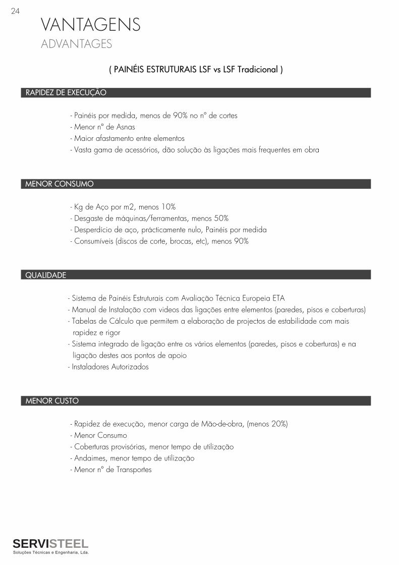
VANTAGENS ADVANTAGES
SERVISTEEL
24
( PAINÉIS ESTRUTURAIS LSF vs LSF Tradicional )
RAPIDEZ DE EXECUÇÃO
- Painéis por medida, menos de 90% no nº de cortes - Menor nº de Asnas - Maior afastamento entre elementos - Vasta gama de acessórios, dão solução às ligações mais frequentes em obra
MENOR CONSUMO
- Kg de Aço por m2, menos 10% - Desgaste de máquinas/ferramentas, menos 50% - Desperdício de aço, prácticamente nulo, Painéis por medida - Consumíveis (discos de corte, brocas, etc), menos 90%
QUALIDADE
- Sistema de Painéis Estruturais com Avaliação Técnica Europeia ETA - Manual de Instalação com videos das ligações entre elementos (paredes, pisos e coberturas) - Tabelas de Cálculo que permitem a elaboração de projectos de estabilidade com mais rapidez e rigor - Sistema integrado de ligação entre os vários elementos (paredes, pisos e coberturas) e na ligação destes aos pontos de apoio - Instaladores Autorizados
MENOR CUSTO
- Rapidez de execução, menor carga de Mão-de-obra, (menos 20%) - Menor Consumo - Coberturas provisórias, menor tempo de utilização - Andaimes, menor tempo de utilização - Menor nº de Transportes

219 944 426
SERVISTEEL, Soluções Técnicas e Engenharia,Lda.
Rua da Galega,Nº 11, Montemuro, 2665-410, St.º Estêvão das Galés, Mafra
Tel. 219 944 426 / Fax. 219 944 427
E-mail: [email protected]
www.servisteel.pt
SE
R-1
7 F
EV