Projeto de um veio - Elementos de Máquinas...
4
RMM, EMI – EM-Ae, EM-Au, EM-E, EM-P, 2015/2016 1 Projeto de um veio - Elementos de Máquinas I Engenharia Mecânica Ramo de: Aeronáutica; Automóvel; Energia; Produção Ano Lectivo 2015/2016 Nome: Numero: Nome: Numero: Nome: Numero: 1. PLANO DE TRABALHO Tarefa Datas a) Entrega do Enunciado do Projeto aos alunos 7 e 11 de Março de 2016 b) Entrega do Relatório ao docente Até 1 de Junho de 2016 c) Apresentação Oral do Projeto por parte dos alunos 8 e 9 de Junho de 2016 2. INTRODUÇÃO E OBJECTIVOS O principal objectivo deste trabalho é o projeto de um veio, incluindo assim a análise dos esforços e o dimensionamento do veio, de modo a que os alunos se familiarizarem com as principais fases de um projeto. Pretende-se projetar o veio intermédio de uma caixa redutora dupla de velocidades de engrenagens cilíndricas de dentes helicoidais (Figura 1). O veio está apoiado em duas chumaceiras de rolamentos e a entrada de movimento é efectuada através da engrenagem 5 que transmite movimento à roda 4 e a saída é realizada pela roda 3 que transmite à 2. As engrenagens transmitem o movimento ao veio através de chavetas. O veio intermédio que se pretende dimensionar encontra-se esquematizado na figura 2. Figura 1 – Esquema e fotografia de uma caixa redutora dupla. 3 2 5 4 Y 2 5 3 4 Roda 4 Roda 3 Veio intermédio
-
Upload
phungkhuong -
Category
Documents
-
view
222 -
download
5
Transcript of Projeto de um veio - Elementos de Máquinas...
RMM, EMI – EM-Ae, EM-Au, EM-E, EM-P, 2015/2016 1
Projeto de um veio - Elementos de Máquinas I
Engenharia Mecânica Ramo de: Aeronáutica; Automóvel; Energia; Produção
Ano Lectivo 2015/2016
Nome: Numero:
Nome: Numero:
Nome: Numero:
1. PLANO DE TRABALHO
Tarefa Datas
a) Entrega do Enunciado do Projeto aos alunos 7 e 11 de Março de 2016
b) Entrega do Relatório ao docente Até 1 de Junho de 2016
c) Apresentação Oral do Projeto por parte dos alunos 8 e 9 de Junho de 2016
2. INTRODUÇÃO E OBJECTIVOS
O principal objectivo deste trabalho é o projeto de um veio, incluindo assim a análise dos esforços e
o dimensionamento do veio, de modo a que os alunos se familiarizarem com as principais fases de
um projeto.
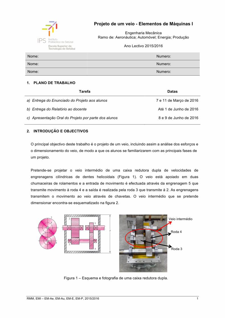
Pretende-se projetar o veio intermédio de uma caixa redutora dupla de velocidades de
engrenagens cilíndricas de dentes helicoidais (Figura 1). O veio está apoiado em duas
chumaceiras de rolamentos e a entrada de movimento é efectuada através da engrenagem 5 que
transmite movimento à roda 4 e a saída é realizada pela roda 3 que transmite à 2. As engrenagens
transmitem o movimento ao veio através de chavetas. O veio intermédio que se pretende
dimensionar encontra-se esquematizado na figura 2.
Figura 1 – Esquema e fotografia de uma caixa redutora dupla.
Budynas−Nisbett: Shigley’s
Mechanical Engineering
Design, Eighth Edition
III. Design of Mechanical
Elements
18. Power Transmission
Case Study
910 © The McGraw−Hill
Companies, 2008
914 Mechanical Engineering Design
Transmission of power from a source, such as an engine or motor, through a machine to anoutput actuation is one of the most common machine tasks. An efficient means of trans-mitting power is through rotary motion of a shaft that is supported by bearings. Gears, beltpulleys, or chain sprockets may be incorporated to provide for torque and speed changesbetween shafts. Most shafts are cylindrical (solid or hollow), and include stepped diame-ters with shoulders to accommodate the positioning and support of bearings, gears, etc.
The design of a system to transmit power requires attention to the design and selec-tion of individual components (gears, bearings, shaft, etc.). However, as is often the casein design, these components are not independent. For example, in order to design theshaft for stress and deflection, it is necessary to know the applied forces. If the forces aretransmitted through gears, it is necessary to know the gear specifications in order todetermine the forces that will be transmitted to the shaft. But stock gears come with cer-tain bore sizes, requiring knowledge of the necessary shaft diameter. It is no surprise thatthe design process is interdependent and iterative, but where should a designer start?
The nature of machine design textbooks is to focus on each component separately. Thischapter will focus on an overview of a power transmission system design, demonstratinghow to incorporate the details of each component into an overall design process. A typicaltwo-stage gear reduction such as shown in Fig. 18–1 will be assumed for this discussion.The design sequence is similar for variations of this particular transmission system.
The following outline will help clarify a logical design sequence. Discussion ofhow each part of the outline affects the overall design process will be given in sequencein this chapter. Details on the specifics for designing and selecting major componentsare covered in separate chapters, particularly Chap. 7 on shaft design, Chap. 11 on bear-ing selection, and Chaps. 13 and 14 on gear specification. A complete case study is pre-sented as a specific vehicle to demonstrate the process.
3
2
5
4
Y
2
5
3 4
Figure 18–1
A compound reverted gear train.
CASE STUDY PART 1 PROBLEM SPECIFICATIONSection 1–16, p. 23, presents the background for this case study involving a speedreducer. A two-stage, compound reverted gear train such as shown in Fig. 18–1will be designed. In this chapter, the design of the intermediate shaft and itscomponents is presented, taking into account the other shafts as necessary.
Roda 4
Roda 3
Veio intermédio

RMM, EMI – EM-Ae, EM-Au, EM-E, EM-P, 2015/2016 2
Figura 2 – Esquema do veio intermédio.
As forças aplicadas nas engrenagens que se localizam nas secções 2 e 4 estão representadas na
Figura 3 e são dadas por: 𝑭𝟓𝟒 =𝑾𝟓𝟒𝒂! +𝑾𝟓𝟒𝒓! +𝑾𝟓𝟒𝒕𝒌 e 𝑭𝟐𝟑 =𝑾𝟐𝟑𝒂! +𝑾𝟐𝟑𝒓! +𝑾𝟐𝟑𝒕𝒌.
em que: 𝑾𝟓𝟒𝒂 = −𝑭𝟓𝟒𝒄𝒐𝒔𝝓𝒏𝒔𝒆𝒏𝝍; 𝑾𝟓𝟒𝒓 = −𝑭𝟓𝟒𝒔𝒆𝒏𝝓𝒏; 𝑾𝟓𝟒𝒕 = 𝑭𝟓𝟒𝒄𝒐𝒔𝝓𝒏𝒄𝒐𝒔𝝍
e: 𝑾𝟐𝟑𝒂 = 𝑭𝟐𝟑𝒄𝒐𝒔𝝓𝒏𝒔𝒆𝒏𝝍; 𝑾𝟐𝟑𝒓 = −𝑭𝟐𝟑𝒔𝒆𝒏𝝓𝒏; 𝑾𝟐𝟑𝒕 = −𝑭𝟐𝟑𝒄𝒐𝒔𝝓𝒏𝒄𝒐𝒔𝝍
e: 𝑾𝟓𝟒𝒕× 𝒓𝒓𝒐𝒅𝒂𝟒 =𝑾𝟐𝟑𝒕× 𝒓𝒓𝒐𝒅𝒂𝟑
Figura 3 – Esquema das forças aplicadas nas engrenagens.
Em que:
𝑊! - Força axial (ao longo do eixo do veio)
𝑊! - Força radial (ao longo do raio da roda)
𝑊! - Força tangencial (tangente à roda)
𝑊 - Força total
Figura 4 – Esquema de forças numa roda
dentada cilíndrica de dentes helicoidais.
Budynas−Nisbett: Shigley’s
Mechanical Engineering
Design, Eighth Edition
III. Design of Mechanical
Elements
13. Gears — General 691© The McGraw−Hill
Companies, 2008
692 Mechanical Engineering Design
First we see that Fy
C = 140 lbf, and so
Answer FC = 118i + 140j − 251k lbf
Then, from Eq. (5),
Answer FD = −71.4i − 155k lbf
These are all shown in Fig. 13–36b in the proper directions.The analysis for the pinionshaft is quite similar.
13–16 Force Analysis—Helical GearingFigure 13–37 is a three-dimensional view of the forces acting against a helical-geartooth. The point of application of the forces is in the pitch plane and in the center of thegear face. From the geometry of the figure, the three components of the total (normal)tooth force W are
Wr = W sin φn
Wt = W cos φn cos ψ
Wa = W cos φn sin ψ
(13–39)
where W = total force
Wr = radial component
Wt = tangential component, also called transmitted load
Wa = axial component, also called thrust load
W
z
y
x
Wa
Wr
Wt
!n
!t"
"
Tooth element
Pitchcylinder
Figure 13–37
Tooth forces acting on a right-hand helical gear.
𝑥
𝑦
𝑧
𝑊!"! 𝑊!"!
𝑊!"!
𝑊!"! 𝑊!"!
𝑊!"!
𝑅!"
𝑅!!
𝑅!!
𝑅!!
𝑅!!

RMM, EMI – EM-Ae, EM-Au, EM-E, EM-P, 2015/2016 3
3. DADOS
A escolha de qualquer dado omisso neste enunciado e considerado necessário aos cálculos, deverá ser justificado na memória descritiva.
Grupo n.º
Material do veio 𝑳𝟏 [𝒎𝒎] 𝑳𝟐 [𝒎𝒎] 𝑳𝟑 [𝒎𝒎] 𝑳𝟒 [𝒎𝒎] 𝑳𝟓 [𝒎𝒎] 𝒓𝟑 (𝒎𝒎) 𝒓𝟒 (𝒎𝒎) 𝑭𝟓𝟒 [𝒌𝑵] 𝝓𝒏 [°] 𝝍 [°]
1 AISI1030CD 200 800 200 200 200 100 200 1 20 30
2 AISI1035CD 100 400 100 200 100 50 100 1,5 20 30
3 AISI1040HR 50 200 50 200 50 25 50 2 20 30
4 AISI1020CD 300 900 300 200 300 150 300 2,5 20 30
5 AISI1015CD 400 900 400 200 400 200 400 3 20 30
6 AISI1030HR 250 700 250 200 250 125 250 3,5 20 30
7 AISI1035HR 350 650 350 200 350 175 350 4 20 30
8 AISI1040CD 150 400 150 200 150 75 150 4,5 20 30
9 AISI1020HR 150 200 150 200 150 80 160 5 20 30
10 AISI1015HR 275 875 275 200 275 125 250 5,5 20 30
11 AISI1030CD 275 875 275 200 275 150 300 6 20 30
12 AISI1035CD 200 800 200 200 200 130 260 6,5 20 30
13 AISI1040HR 100 400 100 200 100 275 450 7 20 30
14 AISI1040HR 50 200 50 200 50 100 200 7,5 20 30
15 AISI1040HR 300 900 300 200 300 50 100 8 20 30
16 AISI1040HR 400 900 400 200 400 25 50 8,5 20 30
17 AISI1030HR 350 650 350 200 350 150 300 9 20 30
18 AISI1035HR 150 400 150 200 150 200 400 9,5 20 30
19 AISI1040CD 150 200 150 200 150 125 250 10 20 30
20 AISI1020HR 275 875 275 200 275 175 350 10,5 20 30

RMM, EMI – EM-Ae, EM-Au, EM-E, EM-P, 2015/2016 4
4. RELATÓRIO O relatório deverá conter:
a. Cálculo das reações nos apoios (rolamentos).
b. Projeto estático do veio. • Cálculo da secção crítica do veio; • Dimensionamento estático da secção crítica, dimensionando de todas as secções do veio;
incluir diagramas de esforços (pode utilizar o software “MDSolids” http://www.mdsolids.com).
c. Projeto à fadiga do veio. • Dimensionamento à fadiga da secção crítica e dimensionando de todas as secções do veio;
incluir diagramas de esforços.
d. Dimensionamento e escolha dos rolamentos SKF calculando a vida.
e. Dimensionamento das chavetas e escatéis.
f. Desenho pormenorizado do veio. • Desenho do veio de acordo com as normas de desenho técnico, com todas as dimensões e
tolerâncias necessárias para o seu fabrico. (não esquecer: vistas, perspectiva isométrica, esquadria e legenda).
g. Desenho de conjunto do veio e dos seus componentes. • Desenho de conjunto de acordo com as normas de desenho técnico, com as dimensões de
atravancamento assim como a lista de peças (B.O.M.). (não esquecer: vistas, perspectiva isométrica, esquadria e legenda).
h. Não esquecer de juntar o enunciado ao relatório.
O Relatório deverá também conter as seguintes partes:
1) Página de Rosto (com identificações genéricas: título, autores, instituição, datação, etc.); 2) Índice (das partes do Relatório); 3) Função, Descrição e Operação do Mecanismo (Memória descritiva); Análise de Opções
(vantagens e inconvenientes, considerações de custos-benefícios); 4) Nota de Cálculo de Projeto (critério de projeto, modelo analítico, método de cálculo, seleção
de material e processo de fabrico, margem de segurança); 5) Observações Gerais (áreas de potencial desenvolvimento: extensão de funções ou
aperfeiçoamento do método de cálculo face ao utilizado, autocrítica quanto a pontos potencialmente críticos não tidos em consideração, etc.);
6) Referências bibliográficas. (Referir sempre as fontes de informação consultadas). 7) Anexos (tabelas e desenhos).