
½s³Z@¿ Ï.pê#R s |ÿb|èEOF½ /° ; H= ¢J b ÏÆa vOõn Ç{ Ï G³ô L ...
31
Product review report Performance of Stramit Uniguard wall systems against NCC 2019 Client: Promat Australia Pty Ltd Product: NCC Class 7b and 8 Type C construction external walls within 3 metres of the boundary Job number: FAS190166 Report No: 22765300-RPT01 Revision: R6.0 Issue date: 3 October 2019 Expiry date: 31 October 2024
Transcript of ½s³Z@¿ Ï.pê#R s |ÿb|èEOF½ /° ; H= ¢J b ÏÆa vOõn Ç{ Ï G³ô L ...

Product rev iew repor t
P e r f o r m a n c e o f S t r a m i t U n i g u a r d w a l l s y s t e m s a g a i n s t
N C C 2 0 1 9
Client: Promat Australia Pty Ltd
Product: NCC Class 7b and 8 Type C construction external walls within 3 metres of the boundary
Job number: FAS190166 Report No: 22765300-RPT01 Revision: R6.0
Issue date: 3 October 2019 Expiry date: 31 October 2024

Product review report No.22765300-RPT01-R6.0
20191003-2275300-RPT01-R6.0 QA version: 04 June 2019 Page 2 of 31
Amendment schedule
Previous versions of reports
Version Date Description Prepared by Reviewed by
0 28/05/2008 Update of WFRA 40981B V3.0 to BCA 2008 Vincent Chow Nabeel Kurban
1 30/05/2008 Correction to revision history Vincent Chow Nabeel Kurban
2 13/08/2010 Update of report to BCA 2010 Peter Gardner Keith Nicholls
3 29/04/2013 Update of report to BCA 2013 Peter Gardner Keith Nicholls/ Simon Krishnan (QLD RPEQ No. 13510)
4 12/08/2014 Update of report to BCA 2014 Peter Gardner Keith Nicholls/ Simon Krishnan (QLD RPEQ No. 13510)
5 18/03/2016 Update of report to BCA 2016 Peter Gardner Keith Nicholls/ Simon Krishnan (QLD RPEQ No. 13510)
Version Date Information relating to report
R6.0 Issue:
03/10/2019
Reason for issue Updated to NCC 2019 and reformatted report.
Prepared by Reviewed by Approved by
Expiry:
31/10/2024
Name Hon Wong Mahmoud Akl Kjetil Pedersen
(QLD RPEQ No 18528)
Signature

Product review report No.22765300-RPT01-R6.0
20191003-2275300-RPT01-R6.0 QA version: 04 June 2019 Page 3 of 31
Contact information
Warringtonfire Australia Pty Ltd – ABN 81 050 241 524
Melbourne – NATA registered laboratory Unit 2, 409-411 Hammond Road Dandenong South, VIC 3175 Australia T: +61 3 9767 1000
Sydney Suite 802, Level 8 383 Kent Street Sydney, NSW 2000 Australia T: +61 2 9211 4333
Brisbane Suite 6, Level 12 133 Mary Street Brisbane, QLD 4000 Australia T: +61 7 3238 1700
Canberra Unit 2, 11 Murray Crescent Griffith, ACT 2603 Australia T: +61 2 6260 8488
Perth Unit 22, 22 Railway Road Subiaco, WA 6008 Australia T: +61 8 9382 3844
General conditions of use
This report may only be reproduced in full without modifications by the report sponsor. Copies, extracts or abridgments of this report in any form must not be published by other organisations or individuals without the permission of Warringtonfire Australia.
Warringtonfire Australia is not able to discuss the contents of this report with third parties without the consent of the report sponsor(s).
All work and services carried out by Warringtonfire Australia are subject to, and conducted in accordance with our standard terms and conditions. These are available at https://www.element.com/terms/terms-and-conditions or on request.
Exova Warringtonfire rebranded to Warringtonfire on 1 December 2018. Apart from the change to our brand name, no other changes have occurred. The introduction of our new brand name does not affect the validity of existing documents previously issued by us.
Product review report No.22765300-RPT01-R6.0
20191003-2275300-RPT01-R6.0 QA version: 04 June 2019 Page 4 of 31
Executive summary
Warringtonfire Australia Pty Ltd had been appointed by Promat Australia Pty Ltd to formulate an opinion on the expected performance of Stramit Uniguard – Fire Resisting Wall System as an external wall system for NCC Class 7b and 8 buildings of Type C Construction within 3m of the boundary, as defined in the National Construction Code (NCC).
This report updates the previous version 5 of this report in consideration of NCC 2019. Promat Australia Pty Ltd has confirmed that the product has not changed since the original assessment was procured.
The wall system comprises a 15mm thick Promina 60 calcium silicate board overlaid externally with horizontal steel battens clad with a 0.42 – 0.48mm BMT (bare metal thickness) Stramit® Corrugated, Stramit® Monoclad® or Stramit Longspan® steel cladding fixed to horizontal battens.
The wall system varies from the NCC Deemed-to-Satisfy Provisions for external walls within 3m of the boundary in that it has been evaluated against the requirements of the NCC Verification Method CV1 instead of being subjected to a standard fire resistance test.
The proposed fire safety design solution, specific to the use of the subject proprietary Stramit Uniguard – Fire Resisting Wall System in circumstances described in this report, has been considered against the relevant NCC Performance Requirements CP1 and CP2 to the extent that they apply to fire spread to the building via the external walls
Based on the discussion in this report, technical specification derived in Appendix A, Test Report 40981 and Appendix B of AS 1530.4:2014, it is the opinion of Warringtonfire Australia Pty Ltd that the proposed fire safety design solution satisfies the relevant NCC 2019 Performance Requirements CP1 and CP2.
It should be noted that this report must be submitted to the relevant regulatory authorities having jurisdiction and relevant stakeholders at the preliminary design stage to obtain acceptance of the proposed fire safety design solution.
Approval for the use of any material, form of construction or design in a building is subject to the relevant building regulations in each jurisdiction. No liability is accepted if this report is not accepted by stakeholders or the relevant regulatory authorities.
The analysis are documented in section 2 to section 7 of this report. The assessment found that the proposed variations are likely to achieve compliance with NCC 2019 for an external wall system when constructed in Class 7b and 8 buildings of Type C construction. The system is required to have a fire resistance level (FRL) of at least 90/90/90 if located within 1.5 metres from a property boundary/fire source feature and FRL of 60/60/60 if located between 1.5 to less than 3 metres from the property boundary /fire source feature.
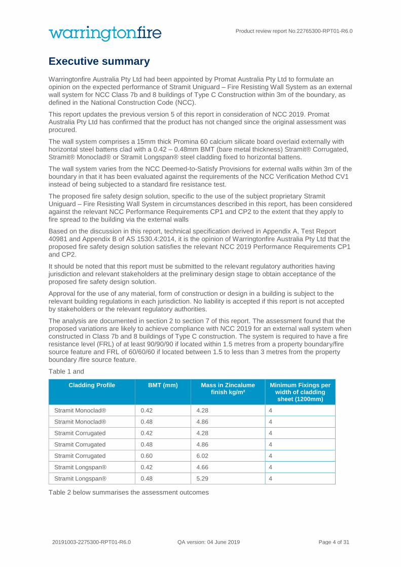
Table 1 and
Cladding Profile BMT (mm) Mass in Zincalume finish kg/m²
Minimum Fixings per width of cladding sheet (1200mm)
Stramit Monoclad® 0.42 4.28 4
Stramit Monoclad® 0.48 4.86 4
Stramit Corrugated 0.42 4.28 4
Stramit Corrugated 0.48 4.86 4
Stramit Corrugated 0.60 6.02 4
Stramit Longspan® 0.42 4.66 4
Stramit Longspan® 0.48 5.29 4
Table 2 below summarises the assessment outcomes
Product review report No.22765300-RPT01-R6.0
20191003-2275300-RPT01-R6.0 QA version: 04 June 2019 Page 5 of 31
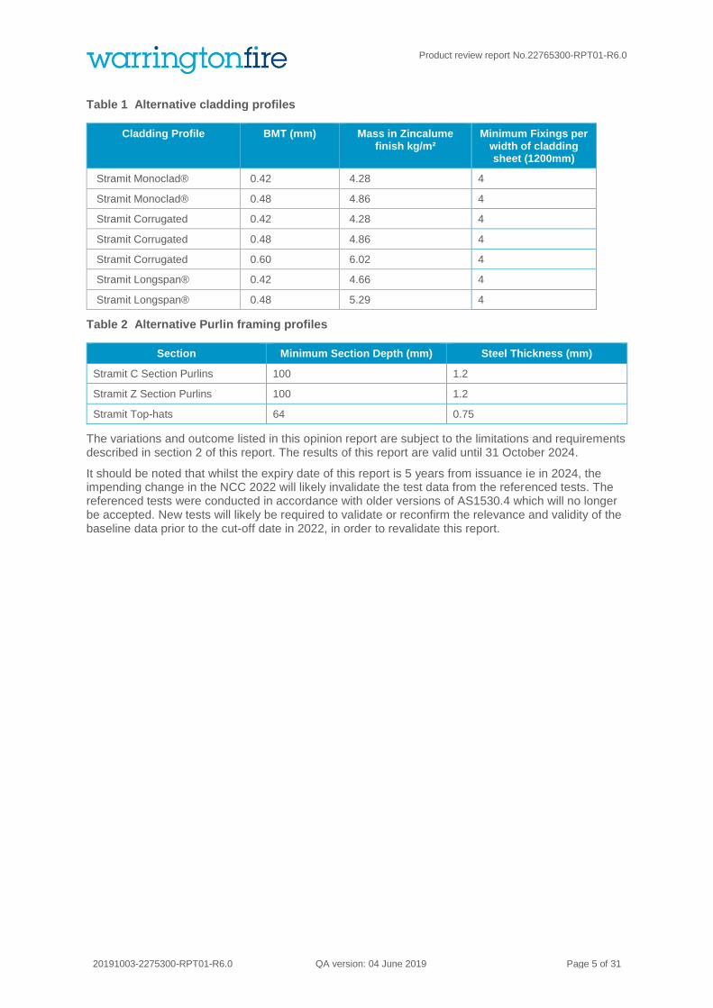
Table 1 Alternative cladding profiles
Cladding Profile BMT (mm) Mass in Zincalume finish kg/m²
Minimum Fixings per width of cladding sheet (1200mm)
Stramit Monoclad® 0.42 4.28 4
Stramit Monoclad® 0.48 4.86 4
Stramit Corrugated 0.42 4.28 4
Stramit Corrugated 0.48 4.86 4
Stramit Corrugated 0.60 6.02 4
Stramit Longspan® 0.42 4.66 4
Stramit Longspan® 0.48 5.29 4
Table 2 Alternative Purlin framing profiles
Section Minimum Section Depth (mm) Steel Thickness (mm)
Stramit C Section Purlins 100 1.2
Stramit Z Section Purlins 100 1.2
Stramit Top-hats 64 0.75
The variations and outcome listed in this opinion report are subject to the limitations and requirements described in section 2 of this report. The results of this report are valid until 31 October 2024.
It should be noted that whilst the expiry date of this report is 5 years from issuance ie in 2024, the impending change in the NCC 2022 will likely invalidate the test data from the referenced tests. The referenced tests were conducted in accordance with older versions of AS1530.4 which will no longer be accepted. New tests will likely be required to validate or reconfirm the relevance and validity of the baseline data prior to the cut-off date in 2022, in order to revalidate this report.

Product review report No.22765300-RPT01-R6.0
20191004-2275300-RPT01-R6.0 Page 6 of 31
Contents
Amendment schedule ............................................................................................................................. 2
Contact information ................................................................................................................................. 3
General conditions of use ....................................................................................................................... 3
Executive summary ................................................................................................................................. 4
1. Introduction ..................................................................................................................................... 7
2. Framework for the assessment ...................................................................................................... 8
3. Description of tested wall system for the proposed fire safety design solution .............................. 8
4. Proposed fire safety design solution for compliance with NCC 2019. .........................................10
4.1 Proposed fire safety design solution ............................................................................................................................... 10 4.2 Acceptable NCC2019 assessment methods .................................................................................................................. 10
Evidence of suitability 10
Performance requirements 11
Relevant NCC 2019 performance requirements 12
4.3 Regulatory assessment.................................................................................................................................................. 13
5. Acceptance criteria .......................................................................................................................14
5.1 NCC 2019 verification method CV1 ................................................................................................................................ 14 5.2 Technical specification ................................................................................................................................................... 14 5.3 AS 1530.4:2014 – Alternative and additional test procedures for elements of construction ............................................ 14
6. Test results ...................................................................................................................................16
7. Acceptable variations to tested systems ......................................................................................17
7.1 Battens between Stramit® cladding and Promina® 60 board. ........................................................................................ 17 7.2 Variations to the steel cladding profile ............................................................................................................................ 18 7.3 Variation to perimeter details of the wall ......................................................................................................................... 18 7.4 Variation to the structural steel framed profile ................................................................................................................ 20
8. Conclusion ....................................................................................................................................22
9. Validity 23
Interpretation and application of NCC verification method CV1 ..................................24
Introduction .................................................................................................................................................................... 24 Overview of NCC Verification method CV1 .................................................................................................................... 24 Evaluation of the ability of a building to withstand levels of heat flux without ignition ...................................................... 24 Criterion for structural adequacy of external walls .......................................................................................................... 27 Summary of failure criteria ............................................................................................................................................. 27
Evacuation calculations ...............................................................................................28
Commentary of AS1530.4:2014 and technical specification of NCC verification method CV1 ..............................................................................................................................29
Supporting FBIM analysis ............................................................................................31

Product review report No.22765300-RPT01-R6.0
20191004-2275300-RPT01-R6.0 Page 7 of 31
1. Introduction
This report presents a fire engineering analysis of a proposed fire safety design solution specific to the use of Stramit Uniguard – Fire Resisting Wall System as an external wall system within 3m of a boundary for Class 7b and 8 buildings of Type C Construction, as defined in the National Construction Code Volume One - Building Code of Australia (NCC) 20191.
The external wall system tested comprised a 15mm thick Promina 60 calcium silicate board overlaid externally with a 0.42mm BMT Stramit Monoclad® steel cladding on the external face.
The NCC Deemed-to-Satisfy Provision C1.1 prescribes that for this classification and type of construction, ie class 7b and 8 of type C construction, load bearing external wall elements are to have the respective fire resistance levels when tested from the outside only:
• Located less than 1.5 metres from a fire source feature – 90/90/90 FRL.
• Located 1.5 metres to less than 3 metres from a fire source feature – 60/60/60 FRL.
A fire safety design solution is proposed to use the subject Stramit Uniguard – Fire Resisting Wall System as an external wall element, evaluated against BCA Verification Method CV1 to demonstrate compliance with NCC Performance Requirements CP1 and CP2.
Whilst NCC Verification Method CV1 defines the acceptance criterion for the exposure of external walls to a radiant heat flux, it is necessary to derive further acceptance criteria to manage the potential of ignition of the contents of the building and ignition of the wall itself2. The derivation of these acceptance criteria, additional to NCC Verification Method CV1, is provided in Appendix 1 - Interpretation and Application of Verification Method CV1 for Class 7b and 8 buildings of Type C Construction.
The wall system has been tested by subjecting it to a radiant heat flux of 80 kW/m². Results of the test are reported in WFRA 40981A3 and analysis of the results against the acceptance criteria presented in this report. The requirements of NCC Deemed-to-Satisfy Provision C1.8 have not been included in this report.
This opinion report documents the findings in determining the likely performance of an external wall system through the application of a fire safety design solution to achieve the compliance requirements of NCC 2019. The application is for Class 7b and 8 buildings of Type C construction having a fire resistance level (FRL) of at least 90/90/90 if located within 1.5 metres from a property boundary/fire source feature. The required FRL of the wall systems shall be at least 60/60/60 if the wall system is located between 1.5 to less than 3 metres from the property boundary/fire source feature, if tested in accordance with AS 1530.4:2014. This opinion report was conducted at the request of Promat Australia Pty Ltd. The sponsor details are included in Table 3.
Table 3 Sponsor details
Client Address
Promat Australia Pty Ltd 1 Scotland Road
Mile End South
Adelaide, SA 5031
Australia
1 National Construction Code Volume One - Building Code of Australia 2019, Australian Building Codes Board, Australia. 2 Babrauskas,V. “Ignition of Wood: A Review of the State of the Art”, Journal of Fire Protection Engineering, Vol 12, No. 3, 2002 3 3m×3m Radiant panel test on an External Wall comprising Monoclad zinc alumel steel sheeting and 15mm thick Promina 60 board

Product review report No.22765300-RPT01-R6.0
20191004-2275300-RPT01-R6.0 Page 8 of 31
2. Framework for the assessment
An assessment is an opinion about the likely performance of a component or element of structure if it were subject to a standard fire test.
No specific framework, methodology, standard or guidance documents exists in Australia for doing these assessments. Therefore, we have followed the Guide to Undertaking Assessments In Lieu of Fire Tests prepared by the Passive Fire Protection Federation (PFPF) in the UK4.
This guide provides a framework to undertake assessments in the absence of specific fire test results. ‘Some areas where assessments may be offered are:
▪ Where a modification is made to a construction which has already been tested
▪ Interpolation or extrapolation of results of a series of fire resistance tests, or utilisation of a series of fire test results to evaluate a range of variables in a construction design or a product
▪ Where, for various reasons – eg size or configuration – it is not possible to subject a construction or a product to a fire test.’
Assessments will vary from relatively simple judgements on small changes to a product or construction through to detailed and often complex engineering assessments of large or sophisticated constructions.
3. Description of tested wall system for the proposed fire safety design solution
The tested wall system comprises a 15mm thick Promina 60 board overlaid with a Monoclad steel cladding (refer to Figure 1) on the exposed (external) face (refer to Figure 3 and Figure 4). The panel boards are nominally 1220mm × 2440mm × 15mm and are butt-jointed without treatment. The Monoclad steel cladding
panels are 0.42mm BMT (code MC42ZA) and 762mm 4mm wide. They are screw-fixed through the Promina 60 board into horizontal steel purlins (C15012, Figure 2) and are installed with 1 flute overlap on the exposed face.
Figure 1 0.42mm BMT Monoclad steel cladding
5 M.Hurley(ed.), SFPE Handbook of Fire Protection Engineering, DOI 10.1007/978-1-4939-2565-0_1©Society of Fire Protection Engineers 2016

Product review report No.22765300-RPT01-R6.0
20191004-2275300-RPT01-R6.0 Page 9 of 31
Figure 2 C15012 steel purlins
Figure 3 Exposed side of wall system

Product review report No.22765300-RPT01-R6.0
20191004-2275300-RPT01-R6.0 Page 10 of 31
Figure 4 Unexposed side of wall system
4. Proposed fire safety design solution for compliance with NCC 2019.
This section describes the extent of variation from deemed-to-satisfy provisions and the application of a fire safety design solution for compliance with the NCC 2019 deemed-to-satisfy provision.
NCC 2019 Specification C1.1 Table 5 prescribes that a load bearing external wall building element within 1.5m of a fire source feature is to achieve an FRL of 90/90/90 for buildings of Type C construction. In addition, BCA Clause 5.1 (b) stipulates, “an external wall that is required by Table 6 to have an FRL need only be tested from the outside to satisfy the requirement.”
Compliance with NCC Deemed-to-Satisfy Provision C1.8 relating to the resistance of the wall from static pressure, impact and surface indentation has not been included in the scope of this analysis.
4.1 Proposed fire safety design solution
Instead of evaluating the prescribed fire resistance level, the proposed fire safety design solution includes analysing the resistance to fire spread and structural adequacy, when exposed to an incident radiation heat flux of 80kW/m² on the external face, commensurate to the relevant NCC 2019 Performance Requirements.
This report is written on the basis of test evidence and understanding of the Performance Requirements of NCC 2019. This has been further set out in the next sections.
4.2 Acceptable NCC2019 assessment methods
Evidence of suitability
Section A5.2 (1)(d) sets out one of the routes for demonstrating compliance. Excerpt from NCC 2019 is shown in Figure 5.

Product review report No.22765300-RPT01-R6.0
20191004-2275300-RPT01-R6.0 Page 11 of 31
Figure 5 Excerpt from Part A5 of NCC 2019
Performance requirements
In order to demonstrate compliance with the NCC 2019, Clause A2.0 requires compliance with the NCC 2019 Performance Requirements.
NCC 2019 Clause A2.1 states that compliance with the Performance Requirements can only be achieved by (Extract from NCC 2019 Clause A2.1):
Figure 6 Performance requirements extracted from NCC2019

Product review report No.22765300-RPT01-R6.0
20191004-2275300-RPT01-R6.0 Page 12 of 31
As permitted by A2.1(3), a combination of A2.1(1) and (2) will be used to demonstrate compliance.
NCC 2019 Clause A2.2(2) identifies assessment methods that are to be used for determining that a performance solution complies with the NCC 2019 Performance Requirements. Extract from NCC 2019 below.
Figure 7 Definition of Performance Solution extracted from the NCC
Relevant NCC 2019 performance requirements
The ability of external walls to resist fire spread and maintain structural adequacy when exposed to external fires will be assessed against the relevant NCC 2019 Performance Requirements. These have been identified as NCC 2019 Performance Requirements CP1 and CP2 having regard for the requirements of A2.2.
These NCC 2019 Performance Requirements require consideration to the spread of fire between buildings.
As the building is of Type C Construction, guidance in the NCC Deemed-to-Satisfy Provisions is provided in NCC Specification C1.1 Clause 5.1 (b) that stipulates that an external wall that is required by Table 6 to have an FRL need only be tested from the outside to satisfy the requirement. This provides indication to the NCC intended hazard for fire spread for Type C Construction circumstances. Support of this direction of fire hazard is reinforced by NCC Deemed-to-Satisfy Provision C3.2 which prescribes that if wall wetting sprinklers are used to protect openings in the external wall, they are located externally. Based on the above, this analysis will only consider resistance to an external fire.
NCC 2019 Performance Requirement CP2 – Spread of Fire
CP2 in NCC 2019 outlines the Deemed to Satisfy provisions for spread of fire. Since the NCC Deemed-to-Satisfy Provisions also require a level of structural stability when exposed to external fire conditions, NCC Performance Requirement CP1 - structural stability during a fire will also be considered.
The primary NCC 2019 Performance Requirements in CP2 for spread of fire and CP1 for structural stability during a fire (as extracted from NCC 2019) are as stated below:
Figure 8 Deemed to Satisfy provisions for structural stability during fire

Product review report No.22765300-RPT01-R6.0
20191004-2275300-RPT01-R6.0 Page 13 of 31
Figure 9 Deemed to satisfy provisions for spread of fire
4.3 Regulatory assessment
As identified previously, the relevant NCC 2019 Deemed-to-Satisfy Provisions prescribe that the fire resistance level of an external wall in a building of Type C Construction need only be considered from the external side. The issue of fire spread between buildings is identified in NCC Performance Requirement CP2 (a)(iii).
It therefore follows that the suitability of an external wall in a building of Type C Construction, which is designed to resist fire spread and maintain structural adequacy when exposed to fire, need only be considered from the external side to demonstrate equivalency to the NCC Deemed-to-Satisfy Provisions. This is appropriate provided all factors in NCC Performance Requirement CP2 (b) being consistent with a building which complies with the NCC Deemed-to-Satisfy Provisions.
The method of regulatory assessment by the Authorities Having Jurisdiction is therefore a determination of the proposed fire safety design solution against NCC 2019 Performance Requirement CP2(a)(iii) and compliance with the Deemed-to-Satisfy Provisions for other parts of Performance Requirement CP2, as permitted in Clause A2.1(3).
The proposed fire safety design solution for NCC 2019 Performance Requirement CP2 (a)(iii) can then be determined using the NCC Verification Method CV1 (b), which identifies a heat flux of 80 kW/m² that the building must withstand without ignition when located on the boundary.
NCC 2019 Verification Method CV1(a) is concerned with the ability of the wall to withstand fire exposure from the internal side, which is not relevant to this analysis since compliance with the NCC Deemed-to-Satisfy Provisions applies to NCC Verification Method CV1(a), as discussed above.

Product review report No.22765300-RPT01-R6.0
20191004-2275300-RPT01-R6.0 Page 14 of 31
5. Acceptance criteria
The following sub-sections describe the derivation of criteria that were adopted for this analysis.
5.1 NCC 2019 verification method CV1
Figure 10 below shows the details of CV1 extracted from NCC 2019:
Figure 10 Details of CV1 extracted from NCC 2019
NCC 2019 Verification Method CV1 therefore indicates that if the external wall of a single storey building of Type C construction can withstand 80 kW/m² without ignition, when tested only from the outside, then it would meet Performance Requirement CP2(a)(iii) of the NCC for buildings of Type C Construction.
In addition, if structural members maintain their structural adequacy when the external wall is exposed to a radiation heat flux of 80kW/m² from the outside it is considered that NCC 2019 Performance Requirement CP1 has been satisfied for Class 7b and 8 buildings of Type C Construction.
5.2 Technical specification
A technical specification described in Appendix A derived the following analysis criteria based on exposure to a radiation heat flux. The technical specification also derived a standard exposure with the incident radiation progressively increasing from 0 to 80kW/m² during the first 30 minutes after which it is maintained at approximately 80kW/m² up to a period of 240 minutes:
1. Ignition of the non-fire exposed face of the element (i.e. continuous flaming for more than 15s) shall not occur during the 240 minute test.
2. The measured radiant heat flux emitted from the non-fire side and from any feature more than 0.01m² of exposed area shall not exceed 10kW/m² during the 240 minute test. This can be measured directly using a radiometer, or the non-fire side temperature can be measured in accordance with AS 1530.4:1997 and a limiting temperature of 435°C applied to the mean temperature of the non-fire side or feature.
3. The element shall remain imperforate (no straight through gaps form) during the 240 minute test. 4. The mean temperature of structural steel members on the inside of the wall system should not
exceed 400°C during the 240 minute test. 5. The temperature at any point on the non-fire side shall not exceed 380°C during the first 60 minutes
of the test when measured by thermocouples complying with AS 1530.4-1997.
5.3 AS 1530.4:2014 – Alternative and additional test procedures for elements of construction
The test protocol developed above and subsequent testing of the prototype against this specification, as reported in test report WFRA40981a was undertaken before the release of AS 1530.4:2014.

Product review report No.22765300-RPT01-R6.0
20191004-2275300-RPT01-R6.0 Page 15 of 31
AS 1530.4:2014 includes additional protocols in Appendix B which address alternative test procedures, for elements of construction considering specific radiant heat exposure conditions as well as temperature heating regimes.
Differences in AS 1530.4:2014 have been reviewed in Appendix C and are considered not to affect the conclusions drawn in this report.

Product review report No.22765300-RPT01-R6.0
20191004-2275300-RPT01-R6.0 Page 16 of 31
6. Test results
Test WFRA 40981 was undertaken on a representative section of wall subjected to an incident radiation heat flux progressively increasing to 80kW/m² during the first 30 minutes of the test and then being maintained at 80kW/m² for the remainder of the 240 minute test. The following tables summarise the results of Test WFRA 40981, against the analysis criteria summarised in Section 4.5.
Table 4 Summary of Test Results
Acceptance criteria/ Failure criteria Required time (mins)
Time criteria exceeded (mins)
Criteria satisfied
(Yes / No)
Ignition of the non-fire exposed face of the element (i.e. continuous flaming for more than 15s)
240 No failure at 240 Yes
Mean temperature on the non-fire exposed face exceeds 435°C
240 No failure at 240 Yes
Wall remains imperforate 240 No failure at 240 Yes
Mean temperature of steel structural members exceeds 400°C
240 No failure at 240 Yes
Maximum temperature at any point on the non-fire exposed face exceeds 380°C
60 70 Yes

Product review report No.22765300-RPT01-R6.0
20191004-2275300-RPT01-R6.0 Page 17 of 31
7. Acceptable variations to tested systems
7.1 Battens between Stramit® cladding and Promina® 60 board.
Proposed variation to the system is to incorporate 12.5mm deep galvanised batten over Promina® board and under the steel cladding. The connection of the battens will be via the fixings for the steel cladding
Figure 11 Section of proposed system
By incorporating a gap between the sheeting and the Promina board, heat transfer by conduction and radiation will be reduced and some heat will be lost from of the cavity via convection.
The loss of heat and the less effective conduction and radiation through joints will result in lower overall temperatures on the non-fire side and reduced variation between the temperatures at the joins and the temperatures in the field of the sheet on the unexposed side.
Based on the discussion above and in absence of any detrimental effects, it is considered that incorporating battens between the Stramit cladding and the Promina 60 board will not impair the fire performance of the of the tested prototype reported in WFRA 40981a.

Product review report No.22765300-RPT01-R6.0
20191004-2275300-RPT01-R6.0 Page 18 of 31
7.2 Variations to the steel cladding profile
It is proposed that various profiles of steel cladding be used instead of the tested 0.42mm BMT Stramit Monoclad® (4.28kg/m2). The permitted variations are listed in Table 5 below.
Table 5 Proposed alternative cladding profiles
Cladding Profile BMT (mm) Mass in Zincalume finish kg/m²
Minimum Fixings per width of cladding sheet (1200mm)
Stramit Monoclad® 0.48 4.86 4
Stramit Corrugated 0.42 4.28 4
Stramit Corrugated 0.48 4.86 4
Stramit Corrugated 0.60 6.02 4
Stramit Longspan® 0.42 4.66 4
Stramit Longspan® 0.48 5.29 4
It is proposed that the cladding shall be fixed to battens with fixings that pass through battens at a maximum spacing of 300mm centres (4 per 1200mm width).
The proposed cladding profiles have similar or greater mass (kg/m²) to the tested construction. The proposed mass range can be seen above to vary between 4 and 6.8 kg/m². The proposed steel sheeting are made from mild steel and therefore considered to have a similar response to heating as the tested mild steel sheeting.
7.3 Variation to perimeter details of the wall
The proposed system incorporates details that exclude embers from entering the system at the perimeter.
Figure 12 Base Detail: Option 1

Product review report No.22765300-RPT01-R6.0
20191004-2275300-RPT01-R6.0 Page 19 of 31
Figure 13 Base Detail: Option 2
The proposed base wall details in Figure 12 and Figure 13 make use of galvanised metal flashings that will remain in place when exposed to radiation and will exclude embers from freely entering under the Promina® 60 board at the base of the wall and would not impair the performance of the tested prototype reported in WFRA 40981a.
Figure 14 Corner Detail

Product review report No.22765300-RPT01-R6.0
20191004-2275300-RPT01-R6.0 Page 20 of 31
The proposed corner detail Figure 14 incorporates metal trim profiles that will act to prevent embers from the freely entering the building at the corners. This proposed construction would not impair the performance of tested prototype reported in WFRA 40981a.
Figure 15 Head Detail
The proposed head detail Figure 15 incorporates mineral wool inserted into gaps created in the cladding profile to prevent embers from freely entering the building at the top of the wall. This proposed construction would not impair the performance of the tested prototype reported in WFRA 40981a.
7.4 Variation to the structural steel framed profile
It is proposed that various structural profiles may be used instead of the 1.5mm BMT Stramit Z girts tested in WFRA 40981a.
The purlins act to laterally support the wall system during wind events and laterally stabilise them during the fire and span horizontally between support columns. The purlins do not support any vertical load from above and therefore only support vertical loads consisting of their self-weight.
Based on the above discussion, it is considered that provided that the purlins do not significantly buckle and continue to laterally support the cladding without resulting in collapse, the fire resistance of the wall system will not be significantly impaired. The structural capacity of these elements is discussed below.
It is proposed that the above requirement can be met by various structural sections as listed in Table 6.
Table 6 Steel framing details
Section Minimum Section Depth (mm) Steel Thickness (mm)
Stramit C Section Purlins 100 1.2
Stramit Z Section Purlins 100 1.2
Stramit Top-hats 64 0.75
It is considered that, provided the temperature of the proposed structural sections above do not exceed 400 degrees then, by reference to BS 5950-8-2003 they will retain at least 50% of their structural capacity.
With reference to WFRA 40981a, the critical temperatures on the sheet are summarised in Table 7.
Fill gaps in cladding profile with mineral wool insulation to exclude embers from entering building

Product review report No.22765300-RPT01-R6.0
20191004-2275300-RPT01-R6.0 Page 21 of 31
Table 7 Critical temperature on the steel frame
Location Temperature At 120mins (°C) Temperature At 240mins (°C)
Vertical butt joint 239 356
Inner face central purlin 315 304
The above temperature indicate that the tested purlin reached equilibrium before 120 minutes and the temperature dropped off as the section temperature became more uniform, increasing its ability to shed heat.
The proposed sections are thinner and smaller, the elements will have higher rate of heat transfer. Therefore, the proposed sections are likely to have a quick temperature rise but it will not likely exceed the limiting temperature of 400°C.
Based on the discussion above and in absence of any detrimental effects, it is considered that incorporating battens between the Stramit® cladding and the Promina® 60 board will not impair the fire performance of the of the tested prototype reported in WFRA 40981a.

Product review report No.22765300-RPT01-R6.0
20191004-2275300-RPT01-R6.0 Page 22 of 31
8. Conclusion
The Deemed-to-Satisfy Provisions of NCC 2019 prescribe that a loadbearing external wall system for a Class 7b & 8 buildings (factories and warehouses) of Type C Construction have a fire resistance level (FRL) of at least 90/90/90, if located less than 1.5 metres from a fire source feature.
The proposed fire safety design solution for the external wall is a proprietary Stramit Uniguard – Fire Resisting Wall System which comprises a 15mm thick Promin® 60 board overlaid with 12.5mm deep horizontal battens and any of the cladding profiles nominated in Table 8 on the exposed (external) face and nominated framing from Table 9 on the unexposed face. The perimeter details (Figure 12 to Figure 15) of this report are required to prevent embers from entering the building.
Table 8 Alternative cladding profiles
Cladding Profile BMT (mm)
Stramit Monoclad® 0.42
Stramit Monoclad® 0.48
Stramit Corrugated 0.42
Stramit Corrugated 0.48
Stramit Corrugated 0.60
Stramit Longspan® 0.42
Stramit Longspan® 0.48
Table 9 Alternative Purlin framing profiles
Section Minimum Section Depth (mm) Steel Thickness (mm)
Stramit C Section purlins 100 1.2
Stramit Z Section purlins 100 1.2
Stramit Top-hats 64 0.75
The proposed fire safety design solution specific to the use of the subject proprietary Stramit Uniguard – Fire Resisting Wall System in circumstances described in this report, has been considered against the relevant Performance Requirements CP1 and CP2 of NCC 2019 to the extent that they apply to fire spread to the building via the external walls.
Based on the discussion in this report, technical specification derived in Appendix A, Test Report WFRA 40981a and Appendix B of AS 1530.4:2014, it is the opinion of Warringtonfire Australia Pty Ltd that the proposed fire safety design solution satisfies the relevant NCC Performance Requirements CP1 and CP2.
It is the responsibility and authority of the relevant regulatory authority to approve or refuse any submission in relation to a specific site and building. No liability is accepted if this report is not accepted by stakeholders or the relevant regulatory authorities.

Product review report No.22765300-RPT01-R6.0
20191004-2275300-RPT01-R6.0 Page 23 of 31
9. Validity
Warringtonfire Australia does not endorse the tested or assessed product in any way. The conclusions of this opinion report may be used to directly assess fire hazard, but it should be recognised that a single test method will not provide a full assessment of fire hazard under all conditions.
Due to the nature of fire testing and the consequent difficulty in quantifying the uncertainty of measurement, it is not possible to provide a stated degree of accuracy. The inherent variability in test procedures, materials and methods of construction, and installation may lead to variations in performance between elements of similar construction.
This opinion report is based on information and experience available at the time of preparation. The published procedures for the conduct of tests and the assessment of test results are subject to constant review and improvement. It is therefore recommended that this report be reviewed on or, before, the stated expiry date. Furthermore, with the changes in the NCC 2019, the referenced tests, that were conducted based on older versions than those nominated in the NCC 2019, will no longer be valid and will inevitably invalidate this report. It may be necessary for the sponsor to conduct further test/s in order to determine if the existing baseline test data are still relevant and applicable.
This document has been prepared to document the derivation of proposed acceptance criteria for external walls of Class 7b and 8 buildings of Type C Construction as defined in volume 1 of National Construction Code (NCC) 2019. Whilst due care has been taken during the preparation of this document, no liability will be accepted for any loss or damage resulting from the use of this document in anyway unless the use of the document for a particular application is additionally supported in writing by Warringtonfire Australia Pty Ltd and appropriate test data.
This opinion is provided to the Promat Australia Pty Ltd for its own purposes and we cannot express an opinion on whether it will be accepted by building certifiers or any other third parties for any purpose.

Product review report No.22765300-RPT01-R6.0
20191004-2275300-RPT01-R6.0 Page 24 of 31
Interpretation and application of NCC verification method CV1
Introduction
Based on the extensive use of NCC 2019 Verification Method CV1, the need has been identified for verification method to be interpreted and a more detailed specification provided to ensure consistent application of the method. In particular, it is necessary to develop appropriate pass / fail criteria to enable external wall systems to be evaluated in a manner consistent with the objectives of the NCC 2019
This document presents the specification for an appropriate pass/fail criterion for consideration to fire spread, commensurate to the relevant NCC 2019 Performance Requirements that was adopted for this analysis.
Overview of NCC Verification method CV1
CV1 states the following:
Compliance with CP2(a)(iii) to avoid the spread of fire between buildings on adjoining allotments is verified when it is calculated that-
(a) a building will not cause heat flux in excess of those set out in column 2 of Table CV1 at the location on an adjoining property set out in column 1 of Table CV1; and
(b) when located at the distances from the allotment boundary set out in column 1 of Table CV1, a building is capable of withstanding the heat flux set out in column 2 of Table CV1 without ignition.
Figure 16 Verification method CV1 extracted from NCC 2019
Evaluation of the ability of a building to withstand levels of heat flux without ignition
Limiting heat flux from the non-fire exposed face
Examining the limiting incident radiant heat flux values from NCC 2019 Table CV1, a value of 20kW/m² is specified at a distance of 3m from the boundary. NCC clause C3.2 permits unprotected openings at distances greater than 3m. Therefore, an appropriate acceptance criterion for the verification method, would be that the building element does not ignite and the emitted radiant heat flux from the non-fire-exposed face of the element is maintained below 20kW/m²
Ignition is assumed to mean flaming ignition as opposed to glowing /charring ignition to be consistent with criteria adopted by test methods such as AS 1530.4:2014.
Product review report No.22765300-RPT01-R6.0
20191004-2275300-RPT01-R6.0 Page 25 of 31
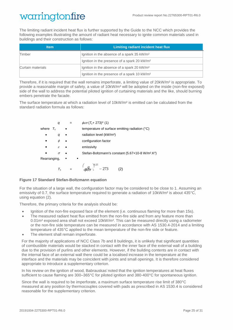
The limiting radiant incident heat flux is further supported by the Guide to the NCC which provides the following examples illustrating the amount of radiant heat necessary to ignite common materials used in buildings and their construction as follows:
Item Limiting radiant incident heat flux
Timber Ignition in the absence of a spark 35 kW/m²
Ignition in the presence of a spark 20 kW/m²
Curtain materials Ignition in the absence of a spark 20 kW/m²
Ignition in the presence of a spark 10 kW/m²
Therefore, if it is required that the wall remains imperforate, a limiting value of 20kW/m² is appropriate. To provide a reasonable margin of safety, a value of 10kW/m² will be adopted on the inside (non-fire exposed) side of the wall to address the potential piloted ignition of curtaining materials and the like, should burning embers penetrate the facade.
The surface temperature at which a radiation level of 10kW/m² is emitted can be calculated from the standard radiation formula as follows:
Figure 17 Standard Stefan-Boltzmann equation
For the situation of a large wall, the configuration factor may be considered to be close to 1. Assuming an emissivity of 0.7, the surface temperature required to generate a radiation of 10kW/m² is about 435°C, using equation (2).
Therefore, the primary criteria for the analysis should be:
• Ignition of the non-fire exposed face of the element (i.e. continuous flaming for more than 15s).
• The measured radiant heat flux emitted from the non-fire side and from any feature more than 0.01m² exposed area shall not exceed 10kW/m². This can be measured directly using a radiometer or the non-fire side temperature can be measured in accordance with AS 1530.4-2014 and a limiting temperature of 435°C applied to the mean temperature of the non-fire side or feature.
• The element shall remain imperforate.
For the majority of applications of NCC Class 7b and 8 buildings, it is unlikely that significant quantities of combustible materials would be stacked in contact with the inner face of the external wall of a building due to the provision of purlins and other elements. However, if the building contents are in contact with the internal face of an external wall there could be a localised increase in the temperature at the interface and the materials may be coincident with joints and small openings. It is therefore considered appropriate to introduce a supplementary criterion.
In his review on the ignition of wood, Babrauskas² noted that the ignition temperatures at heat fluxes sufficient to cause flaming are 300–365°C for piloted ignition and 380-400°C for spontaneous ignition.
Since the wall is required to be imperforate, a maximum surface temperature rise limit of 380°C measured at any position by thermocouples covered with pads as prescribed in AS 1530.4 is considered reasonable for the supplementary criterion.
s
q
q = (T + 273)4 (1)
• where Ts • = • temperature of surface emitting radiation (°C)
• q • = • radiation level (kW/m²)
• • = • configuration factor
• • = • emissivity
• • = • Stefan-Boltzmann's constant (5.67×10⁻⁸ W/m².K4)
• Rearranging, • •
Ts =
0.25 − 273
(2)

Product review report No.22765300-RPT01-R6.0
20191004-2275300-RPT01-R6.0 Page 26 of 31
Fire resistance performance of external walls in Class 7b and 8 Buildings of Type C Construction.
The NCC classification of a building and Type of Construction on adjacent allotments cannot be specified or predetermined and therefore it is not possible to characterise the duration of a fire on an adjacent allotment, and therefore, the period of potential external fire exposure.
It is noted that experimental data is available that shows for many applications, the duration for which a fire burns at a high intensity is often short (in the order of 10 to 20 minutes) but there have been fire incidents where fires have burned for longer durations at high intensities. These longer durations have been considered for the primary criteria assuming no fire brigade intervention.
For the primary criteria which are considered applicable to most applications and required to be consistent with the requirements of NCC Verification Method CV1 and NCC Deemed-to-Satisfy Provision C3.2, an exposure period of 240 minutes inclusive of a 30 minute heating period (refer Figure 18) is considered reasonable since it would be expected to address the majority of fire durations assuming no fire brigade intervention.
Figure 18 The radiant heat flux exposures for various distances from the boundary
However, for the purposes of determining the required period that should be applied to the additional criteria of a maximum limiting temperature rise at any point, fire brigade intervention is considered.
Fire Brigade Intervention
Appendix D shows a general application of the Fire Brigade Intervention Model for industrial buildings using conservative values for rural areas. It is recognized that in extreme cases some periods may be longer (eg. isolated country areas, but the frequency of high density industrial buildings in such areas would also be low). Using the target response times for fire brigades as a benchmark, the time of arrival was calculated to be approximately 18.5 minutes whilst the 90 percentile target for most brigades is under 8 minutes. If the initial fire brigade response has the ability to suppress the fire and/or protect exposures, the threat of fire spread would have been reduced after approximately 23.5 minutes. If additional resources have to be called to protect exposures or the like, it will be approximately 52.5 minutes before the exposures are protected.
The time of an alarm call to the fire brigade will be taken as the time the fire breaks out of the building. At this stage, strong visual, audible and olfactory cues would be provided over large distances. If the building of fire origin is fitted with an automatic fire detection or suppression system connected to a monitoring service or is occupied at the time of the fire a much earlier response would be expected.

Product review report No.22765300-RPT01-R6.0
20191004-2275300-RPT01-R6.0 Page 27 of 31
Based on the above discussion, a reasonable period for application of the supplementary maximum temperature rise criteria would be 60 minutes.
Occupant Evacuation
Appendix C provides a conservative estimate of the time for evacuation of a NCC Class 7b or 8 building of Type C construction. Evacuation would be expected to be completed within 30 minutes of the breakout of the fire indicating that the 60 minute period for the supplementary requirement for the maximum temperature rise includes a reasonable margin of safety.
Criterion for structural adequacy of external walls
The NCC Deemed-to-Satisfy Provisions prescribe that load bearing external wall elements within 3 metres of a fire source feature for a Class 7b or 8 building of Type C construction have a fire resistance level having a structural adequacy component. Therefore, it is considered reasonable that an acceptance criterion be provided to reflect this provision.
NCC Performance Requirement CP1 states that elements are to maintain structural stability, to the degree necessary, during a fire. Therefore, external walls should maintain the structural adequacy of internal members and members in the external walls when exposed to radiant heat from a building on the adjoining allotment.
The residual load-bearing capacity of members can be assessed based on critical temperatures for steel and concrete members. For tests performed on non-loadbearing specimens a critical temperature of 400°C can be adopted for steel elements in contact with the wall to minimise the risk of premature failure. Structural adequacy shall be maintained throughout the 240 minute test.
Summary of failure criteria
In summary, the primary criteria for assessment using NCC Verification Method CV1 should be:
• Ignition of the non-fire exposed face of the element (i.e. continuous flaming for more than 15s).
• The measured radiant heat flux emitted from the non-fire side and from any feature more than 0.01m² expose area shall not exceed 10kW/m². This can be measured directly using a radiometer or the non-fire side temperature can be measured in accordance with AS 1530.4:2014 and a limiting temperature of 435°C applied to the mean temperature of the non-fire side or feature.
• The element shall remain imperforate.
In addition,
• The temperature at any point shall not exceed 380°C during the first 60 minutes of the test when measured by thermocouples complying with AS 1530.4-2014.
• The mean temperature of structural steel members should not exceed 400°C during the 240 minute test.

Product review report No.22765300-RPT01-R6.0
20191004-2275300-RPT01-R6.0 Page 28 of 31
Evacuation calculations
Based on the requirements of NCC clauses D1.4 and D1.5 the maximum travel distance to an exit should not exceed 40m.
Assuming a travel speed of 1.2 m/s the time for evacuation once the occupants have received a fire cue and decided to evacuate would be 34s assuming no cueing etc, For added conservatism, this has been rounded up to one minute.
Based on NCC Table D1.13, the maximum occupant density for a factory or storage building is
0.2 person/m² (5 persons/m²). The maximum area of a building of Type C Construction is prescribed in NCC clause C2.2 to be 2000 m². Therefore, the maximum number of occupants would be 400 Flow speed through the door is assumed to be 50 persons/min5
Assuming all occupants choose to evacuate through one single leaf doorset, it would take approximately 400s (6 min 40 seconds) for the entire population to pass through a single door. For added conservatism, this has been rounded up to 7 minutes.
A fully developed fire in an adjacent building would tend to provide strong cues and multiple visual, audible and olfactory cues. The fire brigade would be expected to arrive on site within 18.5 minutes of the fire breaking out of the adjacent building.
A conservative allowance of 5 minutes after fire brigade arrival for commencement of fire brigade intervention has been included.
Therefore, a very conservative estimate of the evacuation time would be:
Table 10 Details of the evacuation time
Period Time
Instruction to evacuate from Fire Brigade 18.5 minutes
Preparation and alert time 5 minutes
Travel time 1 minute
Queuing time 7 minutes
Total ~ 32 minutes
5 M.Hurley(ed.), SFPE Handbook of Fire Protection Engineering, DOI 10.1007/978-1-4939-2565-0_1©Society of Fire Protection Engineers 2016

Product review report No.22765300-RPT01-R6.0
20191004-2275300-RPT01-R6.0 Page 29 of 31
Commentary of AS1530.4:2014 and technical specification of NCC verification method CV1
Appendix B7 of AS1530.4:2014 provides an informative guide on performance solution test procedures, for elements of construction. In a similar vain to fire resistance testing, they are provided as verification methods for the assessment of construction elements considering specific heating regimes and exposure conditions.
It defines a method for carrying out a fire resistance test on elements exposed to different levels of radiant heat using a 3 m × 3 m furnace. The test may be used to obtain data to assess the performance of external walls using verification methods such as CV1 and CV2 of the NCC
NCC Table CV1 and CV2 are provided to determine exposure conditions to satisfy NCC Verification Method CV1 and CV2.
The performance criteria provided with the appendix B7 of AS 1530.4:2014 states that the performance of the specimen may be assessed against the criteria specified in Section 3. Additional criteria, such as ignition of the face exposed to radiant heat, may also be applicable.
The criteria for failure in AS1530.4:2014 are therefore also considered applicable to radiant heat exposure tests. Determination of structural adequacy, integrity and insulation are to be recorded, as well as a radiation component.
Therefore, the expression of results of a radiant heat exposure test to AS1530.4:2014 would state the following:
Fire performance of the walls when exposed to rr kW/m² of radiant heat:
(a) structural adequacy, xx minutes; and
(b) integrity yy minutes; and
(c) insulation zz minutes.
NOTE: An alternate heating regime to the standard heating regime specified in Section 2 (of AS 1530.4:2014 has been adopted. The results above should not be used as evidence of performance when subjected to the standard heating regime.
This would also be provided with the incident radiant heat flux/time measurements in lieu of the furnace temperature, as stated in Clause B7.4.6 (a) of AS1530.4:2014.
The failure criteria for each component can therefore be stated as follows:
Structural adequacy
Failure in relation to structural adequacy shall be deemed to have occurred upon collapse.
This has been considered similar to condition 4 in Section 5.2 (of this report) which limits the mean temperature of structural steel members on the inside of the wall system.
Integrity
Failure in relation to integrity shall be deemed to have occurred upon collapse, the development of cracks, fissures, or other openings through which flames or hot gases can pass, or upon other occurrences. It is deemed to have collapsed when -
• A 6 mm gap gauge can be passed through the specimen so that the gap gauge projects into the furnace and can be moved a distance of 150 mm along the gap;
• Sustained flaming on the surface of the unexposed face for 10 s or longer constitutes integrity failure.
This has been considered similar to conditions 1 and 3 in Section 5.2 with limits in the ignition of the non-fire exposed face of the element (sustained flaming on the surface of the unexposed face for at least 15s in lieu of 10s) and remaining fully imperforate during the test.

Product review report No.22765300-RPT01-R6.0
20191004-2275300-RPT01-R6.0 Page 30 of 31
Insulation
Failure in relation to insulation shall be deemed to have occurred when measurement of insulation is made by thermocouples on the unexposed face and is deemed to have failed when—
1. the average temperature of the unexposed face of the test specimen, as measured by the thermocouples specified in Clause 2.2.3.1, exceeds the initial temperature by more than 140 K; or
2. the temperature at any location on the unexposed face of the test specimen exceeds the initial temperature by more than 180 K.
The temperature at any point on the non-fire side not exceeding 380°C was used in the assessment presented in this report based on the discussion in Appendix A.3.1 and the observed performance of combustible materials placed against the test specimen during the test described in test report 40981a.
Radiation
Failure in relation to radiation shall be deemed to have occurred when the calculated total heat flux at a distance of 365 mm exceeds 10 kW/m². This is to be determined in accordance with Appendix A of AS 1530.4:2014.
This has been considered as condition 2 in Section 4.2 which provides temperature limits corresponding to 10kW/m² at the un-exposed surface of the building element, rather than at a distance of 365mm from the unexposed surface which is considered to be more conservative.

Product review report No.22765300-RPT01-R6.0
20191004-2275300-RPT01-R6.0 Page 31 of 31
Supporting FBIM analysis
Activity Resources Unit Rate No. of Units Activity Time Elapsed Time
Fire alarm received by fire brigade 0.0
notification (assumed by phone call 10 minutes after initiation) 0 s 1 0.0 s 0.0 s
Dispatch resources and travel to fire scene
Integraph dispatches initial response appliances 30 s 1 30.0 s 30.0 s
firefighters dress, assimilate information and depart station FF1-6 480 s 1 480.0 s 510.0 s
Initial response appliance travel times to arrival on scene
- Pumper 1 FF1-3 60 kph 10 km 600 s 1110 s
- Pumper 2 FF4-6 60 kph 10 km 600 s 1110 s
Initial access to site and fire assessment
P1 & P2 travel through security gate to fire area FF1-6 8 kph 0 km 16 s 1126 s
OIC investigates fire affected area and assesses exposures FF1 1 m/s 100 m 83 s 1210 s
radio for additional resources FF1 30 s 1240 s
additional resources dispatched 60 s 1 60 s 1300 s
OIC discusses building layout and access with security personnel FF1 & security 90 s 2 240 s 1480 s
Dispatch of additional resources
firefighters dress, assimilate information and depart station FF8-12 480 s 1 480 s 1780 s
2nd alarm response appliance travel times to arrival on scene
- Water tanker 1 FF8-12 60 kph 20 km 1200 s 2980 s
- Rescue 1 FF13-16 60 kph 20 km 1200 s 2980 s
- Pumper 3 FF17-20 60 kph 20 km 1200 s 2980 s
Prepare for firefighting & lay hose lines
firefighters dismount appliance P1 and don BA FF2-3 133 s 133 s 1259 s
connect 65mm diameter feed hose from hydrant to P1 and charge FF2 99 s 1 99 s 1358 s
remove and connect 65mm diameter hose from P1 to branch FF3 62 s 1 62 s 1321 s
dismount appliance 2 and don BA FF4-6 133 s 133 s 1259 s
connect 65mm diameter feed hose from hydrant to P2 and charge FF5 99 s 1 99 s 1358 s
remove and connect 2 off 65mm diameter hose from P2 to branch FF5-6 62 s 1 62 s 1420 s
prepare monitor of P2 FF6 30 s 1 30 s 1450 s
Apply water to exposures and fire
charge delivery hoses from P1 FF2 37 s 1 37 s 1395 s
maintain control of P1 FF2 duration of fire
protect exposures of building with hose lines FF3-4 duration of fire
charge delivery hoses from P2 FF5 37 s 1 37 s 1457 s
maintain control of P2 FF5 duration of fire
maintain P2 monitor FF6 duration of fire
Arrival of additional 2nd alarm resources
WT1 travels through security gate FF7-9 2 kph 0 km 36 s 3016 s
R1 travels through security gate FF10-12 2 kph 0 km 36 s 3016 s
P3 travels through security gate FF13-15 2 kph 0 km 36 s 3016 s
firefighters dismount appliance WT1 and don BA FF7-9 133 s 133 s 3149 s
firefighters dismount appliance R1 and don BA FF10-12 133 s 133 s 3149 s
firefighters dismount appliance P3 and don BA FF13-15 133 s 133 s 3149 s
provide hose lines for exposure protection and undertake water relay to ensure supply FF7-15 duration of fire


![Boletim Abril 2017 - Centro Espírita Luz e Verdade$12 ;9, 1Ó0(52 $%5,/ Z µ s ] } o À U î î ò r d o X W ~ î í î ð í ñ r ó õ î ô r W î ï ì ô ì r í ô ì v u }](https://static.fdocumentos.com/doc/165x107/5fe9479b3cff70375040837a/boletim-abril-2017-centro-esprita-luz-e-verdade-12-9-1052-5-z-s.jpg)


![Dr Amrendra N. Tripathi. Hindisggscollegepatnasaheb.com/pdf/Dr Amrendra N. Tripathi. Hindi.pdf · ä ä t E Á o Z ] U / v ] /^ E W õ ó ô r õ ï r ô õ ñ õ ô r í ï r í](https://static.fdocumentos.com/doc/165x107/5fc01a3fce4e7442133b960f/dr-amrendra-n-tripathi-hindis-amrendra-n-tripathi-hindipdf-t-e-o.jpg)


![D Z , EK!> hs - marche-de-noel-beauvais.fr · D Z , EK!> hs /^ t } ] v ] µ î ì í ô ï õ µ [ u ] v t ò ì ì ì ì hs /^ t } v ( ( ] µ X ( t Z ^ ô ì ì ï í õ ï ô ò](https://static.fdocumentos.com/doc/165x107/5f37caced8b37a093e6afac7/d-z-ek-hs-marche-de-noel-d-z-ek-hs-t-v-.jpg)
![Tabela Danfoss Refrigeracao 2019 · 2019-03-09 · '$1)266 5HIULJHUDomR 5$& ] P } ] } W } ì ì ï& í î ï îts&y ï î t s o À ' í í l ð ð r í ó ï ô ô U ñ ì ¦ ì ì](https://static.fdocumentos.com/doc/165x107/5f966e4ea4e0482a1c6df14c/tabela-danfoss-refrigeracao-2019-03-09-1266-5hiuljhudomr-5-p-.jpg)


![E ì ì ò ì ô ï ó ì ì ò ì ô î ì ï ó , sZK> d , sZK> d r î ì ... · / lEDdD l&DDd& D d ] }D } o } D ] ] v d ] } î ì í õ î ì í ô î ì í ó î ì í ò î ì](https://static.fdocumentos.com/doc/165x107/5fb6c4d1df6a3138655e99aa/e-szk-d-szk-d-r-.jpg)
