Aula 30 - Conversores A/D · ELD0001 zProf. Renan Sebem Aula 30 14 / 18. Conversores A/D...
18
Aula 30 - Conversores A/D Prof. Renan Sebem Disciplina de eletrônica digital Departemanto de engenharia elétrica Centro de Ciências Tecnológicas (CCT) Universidade Do Estado de Santa Catarina (UDESC) Joinville-SC – Brasil 16 de Junho de 2015 ELD0001 ‡ Prof. Renan Sebem ‡ Aula 30 1 / 18
Transcript of Aula 30 - Conversores A/D · ELD0001 zProf. Renan Sebem Aula 30 14 / 18. Conversores A/D...

Aula 30 - Conversores A/D
Prof. Renan Sebem
Disciplina de eletrônica digitalDepartemanto de engenharia elétrica
Centro de Ciências Tecnológicas (CCT)Universidade Do Estado de Santa Catarina (UDESC)
Joinville-SC – Brasil
16 de Junho de 2015
ELD0001 ‡ Prof. Renan Sebem ‡ Aula 30 1 / 18

Itens da aula
Avisos
Conversores A/D
Avisos
Referências
ELD0001 ‡ Prof. Renan Sebem ‡ Aula 30 2 / 18

Avisos
I Mudança da data da prova: todos os alunos matriculados devemassinar até dia 28/06;
I Caso contrário, prova: 23/06 às 12:40;I Contadores;I Divisores de frequência;I Temporizador 555;I Conversores A/D e D/A.
I Lista de exercício já está na página;I Exame: 30/06.
ELD0001 ‡ Prof. Renan Sebem ‡ Aula 30 3 / 18

Conversores A/D
Processo de conversão A/D
I Amostragem no tempo;I Quantização em amplitude;I Codificação (geralmente em dado binário ou BCD);
Amostragem Quantizacao CodificacaoInanalogico
Outdigital
ELD0001 ‡ Prof. Renan Sebem ‡ Aula 30 4 / 18
Conversores A/D
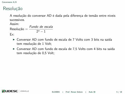
ResoluçãoA resolução do conversor AD é dada pela diferença de tensão entre níveissucessivos.Assim:Resolução =
Fundo de escala
2n − 1Ex:
I Conversor AD com fundo de escala de 7 Volts com 3 bits na saídatem resolução de 1 Volt;
I Conversor AD com fundo de escala de 7,5 Volts com 4 bits na saídatem resolução de 0,5 Volt;
ELD0001 ‡ Prof. Renan Sebem ‡ Aula 30 5 / 18

Conversores A/D
Exemplo - ResoluçãoPara um sinal analógico que pode assumir valores entre 0 e 10 Volts(fundo de escala = 10 V), deseja-se converter o sinal para digital comuma resolução de no máximo 0,1 Volt. Quantos bits deve ser oconversor?
ELD0001 ‡ Prof. Renan Sebem ‡ Aula 30 6 / 18

Conversores A/D
Amostragem através de segurador (sample & hold)
I Como é o sinal de saída do segurador para uma entrada analógicasenoidal?
ELD0001 ‡ Prof. Renan Sebem ‡ Aula 30 7 / 18

Conversores A/D
Conversor AD paralelo (flash)Data Conversion Circuits – D/A and A/D Converters 501
-
+
Comp.C33V/4
-
+
C2V/2
-
+
Comp.C1V/4
krowte
Ngnido
C
s etaG
daeR
S
RQ
S
RQ
21
20
VA
Figure 12.29 Two-bit simultaneous A/D converter.
analogue input signal into a two-bit digital output is shown in Fig. 12.29. The analogue signal to bedigitized serves as one of the inputs to each of the comparators. The second input for each of thecomparators is a reference input, different for each comparator. The reference voltages to be used forcomparators are in general V /2n, 2V /2n, 3V /2n, 4V /2n and so on. Here, V is the maximum amplitudeof the analogue signal that the A/D converter can digitize, and n is the number of bits in the digitizedoutput. In the present case of a two-bit A/D converter, the reference voltages for the three comparatorswill be V /4, V /2 and 3V /4. If we wanted a three-bit output, the reference voltages would have been V /8,V /4, 3V /8, V /2, 5V /8, 3V /4 and 7V /8. Referring to Fig. 12.29, the output status of various comparatorsdepends upon the input analogue signal VA. For instance, when the input VA lies between V /4 and V /2,the C1 output is HIGH whereas the C2 and C3 outputs are both LOW. The results are summarizedin Table 12.1. The three comparator outputs can then be fed to a coding network (comprising logicgates, etc.) to provide two bits that are the digital equivalent of the input analogue voltage. The bits atthe output of the coding network can then be entered into a flip-flop register for storage. Figure 12.30shows the arrangement of a three-bit simultaneous-type A/D converter.
The construction of a simultaneous A/D converter is quite straightforward and relatively easy tounderstand. However, as the number of bits in the desired digital signal increases, the number of
Table 12.1 Simultaneous or Flash A/D converters.
Input analoguevoltage$va%
C1 C2 C3 21 22
0 to V/4 LOW LOW LOW 0 0V/4 to V/2 HIGH LOW LOW 0 1V/2 to 3V/4 HIGH HIGH LOW 1 03V/4 to V HIGH HIGH HIGH 1 1
I OBS: os latches na saída estão com uma conexão simbólica.
ELD0001 ‡ Prof. Renan Sebem ‡ Aula 30 8 / 18
Conversores A/D
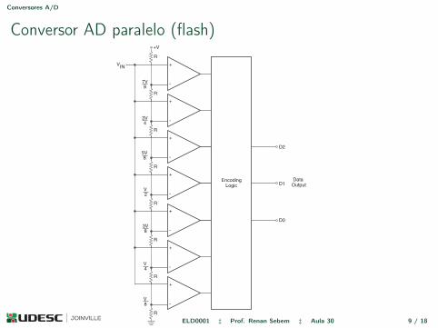
Conversor AD paralelo (flash)502 Digital Electronics
-
+
R
7V8
-
+
R
3V4
-
+
R
5V8
-
+
R
V2
-
+
R
3V8
-
+
R
V4
-
+
R
V8
VIN
+V
EncodingLogic
D2
D1
D0
DataOutput
R
Figure 12.30 Three-bit simultaneous A/D converter.
ELD0001 ‡ Prof. Renan Sebem ‡ Aula 30 9 / 18
Conversores A/D
Exemplo - Conversor FlashCom 12 Volts de fundo de escala e resolução de 0,75 V, desenhe oesquemático de um conversor flash para estas condições.
ELD0001 ‡ Prof. Renan Sebem ‡ Aula 30 10 / 18

Conversores A/D
Conversor AD - rampa
504 Digital Electronics
into digital code using a least significant four-bit A/D converter. The least significant A/D converteris referenced to one-sixteenth (= 1/24% of the reference voltage used by the most significant A/Dconverter. The new four-bit digital output is stored in the least significant four bits of the output latch.The latch now contains the eight-bit digital equivalent of the analogue input. The digitized output isthe same as would be produced by an eight-bit full-flash converter. The only difference is that theconversion process takes a little longer. It may also be mentioned here that the eight-bit half-flashconverter can be used either as a four-bit full-flash converter or as an eight-bit half-flash converter.Some half-flash converters use a single full-flash converter and reuse it for both conversions. This isachieved by using additional sample-and-hold circuitry.
12.11.3 Counter-Type A/D ConverterIt is possible to construct higher-resolution A/D converters with a single comparator by using a variablereference voltage. One such A/D converter is the counter-type A/D converter represented by the blockschematic of Fig. 12.32. The circuit functions as follows. To begin with, the counter is reset to all0s. When a convert signal appears on the start line, the input gate is enabled and the clock pulsesare applied to the clock input of the counter. The counter advances through its normal binary countsequence. The counter output feeds a D/A converter and the staircase waveform generated at the outputof the D/A converter forms one of the inputs of the comparator. The other input to the comparator isthe analogue input signal. Whenever the D/A converter output exceeds the analogue input voltage, thecomparator changes state. The gate is disabled and the counter stops. The counter output at that instantof time is then the required digital output corresponding to the analogue input signal.
The counter-type A/D converter provides a very good method for digitizing to a high resolution.This method is much simpler than the simultaneous method for higher-resolution A/D converters. Thedrawback with this converter is that the required conversion time is longer. Since the counter alwaysbegins from the all 0s position and counts through its normal binary sequence, it may require asmany as 2n counts before conversion is complete. The average conversion time can be taken to be2n/2 = 2n−1 counts. One clock cycle gives one count. As an illustration, if we have a four-bit converterand a 1 MHz clock, the average conversion time would be 8 ms. It would be as large as 0.5 ms for a10-bit converter of this type at a 1 MHz clock rate. In fact, the conversion time doubles for each bit
GateClock Counter
D/AConverter
+ -
AnalogueInput, VA
DigitalOutput
Start
Figure 12.32 Counter-type A/D converter.
I a saída digital é conectada a um registrador quando a conversão éterminada;
I problema: tempo de conversão depende do valor a ser digitalizado.
ELD0001 ‡ Prof. Renan Sebem ‡ Aula 30 11 / 18

Conversores A/D
Exemplo - Conversor AD RampaCom 12 Volts de fundo de escala e resolução de 0,75 V, desenhe ográfico da conversão de um valor analógico de 7 Volts utilizando umconversor rampa.
ELD0001 ‡ Prof. Renan Sebem ‡ Aula 30 12 / 18

Conversores A/D
Conversor AD - aproximação sucessiva
ELD0001 ‡ Prof. Renan Sebem ‡ Aula 30 13 / 18

Conversores A/D
Conversor AD - aproximação sucessiva506 Digital Electronics
1111111011011100101110101001100001110110010101000011001000010000
1111
1101
1011
1001
0111
0101
0011
0001
1110
1010
0110
0010
1100
0100
0000 1000
Figure 12.33 Conversion process in a successive approximation type A/D converter.
Counter
D/AConverter
DigitalOutput
RingCounter
ControlLogicand
Clock
Figure 12.34 Block schematic representation of a successive-approximation A/D converter.
require 2n−1 clock cycles for each conversion, whereas a successive approximation type converterrequires only n clock cycles. That is, an eight-bit A/D converter of this type operating on a 1 MHzclock has a conversion time of 8 )s.
12.11.6 Single-, Dual- and Multislope A/D ConvertersFigure 12.35 shows a block schematic representation of a single-slope A/D converter. In this typeof converter, one of the inputs to the comparator is a ramp of fixed slope, while the other input isthe analogue input to be digitized. The counter and the ramp generator are initially reset to 0s. The
ELD0001 ‡ Prof. Renan Sebem ‡ Aula 30 14 / 18
Conversores A/D
Exemplo - Conversor AD Aproximação SucessivaCom 12 Volts de fundo de escala e resolução de 0,75 V, desenhe ográfico da conversão de um valor analógico de 7 Volts utilizando umconversor de aproximação sucessiva.
ELD0001 ‡ Prof. Renan Sebem ‡ Aula 30 15 / 18

Avisos
I Mudança da data da prova: todos os alunos matriculados devemassinar até dia 28/06;
I Caso contrário, prova: 23/06 às 12:40I Contadores;I Divisores de frequência;I Temporizador 555;I Conversores A/D e D/A.
I Exame: 30/06
ELD0001 ‡ Prof. Renan Sebem ‡ Aula 30 16 / 18

Referências
[1] Ivan V. Idoeta and Francisco Gabriel Capuano. Elementos deEletrônica Digital. São Paulo: Érica, 2014.
[2] Anil K. Maini. Digital Electronics Principles: Devices andApplications. Wiley, 2007.
[3] Ronald J. Tocci. Sistemas Digitais – Princípios e Aplicações. PrenticeHall, 2001.
ELD0001 ‡ Prof. Renan Sebem ‡ Aula 30 17 / 18
Aula 30 - Conversores A/D
Prof. Renan Sebem
Disciplina de eletrônica digitalDepartemanto de engenharia elétrica
Centro de Ciências Tecnológicas (CCT)Universidade Do Estado de Santa Catarina (UDESC)
Joinville-SC – Brasil
16 de Junho de 2015
Obrigado.
ELD0001 ‡ Prof. Renan Sebem ‡ Aula 30 18 / 18