Manual de Instruções para Sensor de Leme RFU17178 Vetus de Leme RFU1718.pdf · 4. 100206.04....
9
Manual de Instruções para Sensor de Leme RFU17178 Vetus Em caso dúvidas na instalação após a leitura do manual, favor entrar em contato com nosso departamento técnico através do telefone ou email: • (11) 3477-5655 • email: [email protected] Horários de atendimento: Segunda-feira à quinta-feira: 8h – 18h Sexta-feira: 8h – 17h Rua Anhaia 982, Bom Retiro – SP www.marineoffice.com.br
Transcript of Manual de Instruções para Sensor de Leme RFU17178 Vetus de Leme RFU1718.pdf · 4. 100206.04....

Manual de Instruções para
Sensor de Leme RFU17178 Vetus
Em caso dúvidas na instalação após a leitura do manual, favor entrar em
contato com nosso departamento técnico através do telefone ou email:
• (11) 3477-5655�
• email: [email protected]
Horários de atendimento:
Segunda-feira à quinta-feira: 8h – 18h
Sexta-feira: 8h – 17h
Rua Anhaia 982, Bom Retiro – SP
www.marineoffice.com.br

Roerstandgever
Rudder feedback unit
Ruderstandsmesser
Indicateur de position du gouvernail
Unidad de reacción del timón
Indicatore di tacco del timone
Copyright © 2007 Vetus den Ouden n.v. Schiedam Hol land
Installatieinstructies 2
Installation instructions 4
Installationsanleitung 6
Instructions d’installation 8
Instrucciones de instalación 10
Istruzioni per l’installazione 12
RFU1718
Salvatore A Italiano
Salvatore A Italiano
Sensor de Leme
Salvatore A Italiano
Salvatore A Italiano
Instruções de instalação
Salvatore A Italiano
4 100206.04 Rudder feedback unit RFU1718
IntroductionNote: The figures printed in bold type point to the drawing numbers on the folding page at the end of this manual.
This rudder feedback unit is designed to be used with the following items:
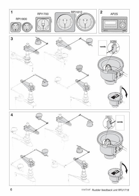
1 Rudder position display types RPI1700, RPI1800 and RPI1810 for single or twin meter installations.
2 Vetus autopilot type AP2S alone or together with single or twin rudder position display units.
Variations in installation 3 If a rudder feedback unit is installed in such a way that a clockwise rotation of the rudder results in a clockwise rotation of the shaft of the rudder feedback unit the connector (X1) must be in position ‘NORM’. The rudder feedback unit is supplied with connector in position ‘NORM’.
4 If a rudder feedback unit is installed in such a way that a clockwise rotation of the rudder results in a counter- clockwise rotation of the shaft of the rudder feed back unit then the connector (X1) must be in position ‘REV’. Reposition the connector (180˚).
Power supplyWith rudder position display units only, the feedback unit may be connected to either 12 or 24 Volt DC supplies.When used with an autopilot with or without rudder position displays it must be connec-ted to the 5 Volt supply from the autopilot.
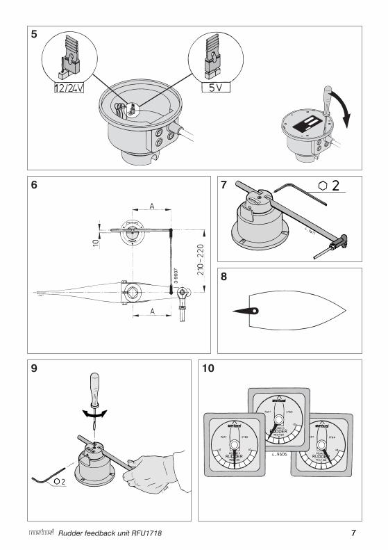
5 The adjustable voltage link must be repositioned in accordance with the diagram, ‘12/24V’ for rudder position display units only and ‘5V’ for combined autopilot and rudder position useage.
Installation 6 Never attempt to install the rudder feedback unit outdoors! Install the rudder feedback unit in such a way that the arm of the feedback unit will accurately follow the tiller arm. Install the rudder feedback unit in such a way that the feedback unit arm together with the tiller arm moves in the same plane. Mount the ball joints on both arms, in such a way, that both distances between rudder axis / ball joint and feedback unit axis / ball joint are equal (A). Choose dimension A in accordance with the available space, preferably as long as possible.
Salvatore A Italiano
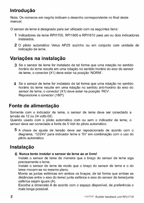
Introdução
Salvatore A Italiano
Nota: Os números em negrito indicam o desenho correspondente no final deste manual.
Salvatore A Italiano
O sensor de leme é designado para ser utilizado com os seguintes itens:
Salvatore A Italiano
Indicadores de leme RPI1700, RPI1800 e RPI1810 para um ou dois indicadores instalados.
Salvatore A Italiano
O piloto automático Vetus AP2S sozinho ou em conjunto com unidade de indicação de leme.
Salvatore A Italiano
Variações na instalação
Salvatore A Italiano
Se o sensor de leme for instalado de tal forma que uma rotação no sentido horário do leme resulte em uma rotação no sentido horário do eixo do sensor de leme, o conector (X1) deve estar na posição ‘NORM’.
Salvatore A Italiano
Se o sensor de leme for instalado de tal forma que uma rotação no sentido horário do leme resulte em uma rotação no sentido anti-horário do eixo do sensor de leme, o conector (X1) deve estar na posição ‘REV’.Reposicione o conector (180º).
Salvatore A Italiano
Fonte de alimentação
Salvatore A Italiano
Somente com o indicador de leme, o sensor de leme deve ser conectado a tensão de 12 ou 24 volts DC.Quando usado com o piloto automático com ou sem o indicador de leme, o sensor deve ser conectado a fonte de 5 Volt do piloto automático.
Salvatore A Italiano
A chave de ajuste de tensão deve ser reposicionado de acordo com o diagrama, ’12/24V’ para indicador leme e ‘5V’ em combinação com o uso do piloto automático
Salvatore A Italiano
Instalação
Salvatore A Italiano
Nunca tente instalar o sensor de leme ao ar livre!
Salvatore A Italiano
Instale o sensor de leme de maneira que o braço do sensor de leme siga precisamente o leme.Instale o sensor de leme de modo que o braço do sensor de leme e o do leme movam-se no mesmo plano.Monte as juntas esféricas em ambos os braços, de tal forma que ambas as distâncias entre o eixo do leme/ junta esférica e eixo do sensor de leme/junta esférica sejam iguais (A).Escolha a dimensão A de acordo com o espaço disponível, de preferência o mais longa possível.
Salvatore A Italiano
2
100206.04 5Rudder feedback unit RFU1718
ENGLISH Mount the rudder feedback unit with the screws supplied.
7 Secure the rod with the set screw.
ConnectionsConnect the power supply to the cable as indicated in the diagram, brown to positive (+) and blue to negative (-, ground).Install the cable, or cables, from rudder feedback unit to each instrument and insert the plug into the rudder feedback unit.
Adjustment of rudder feedback shaft 8 Switch on power supply of both the rudder feedback unit and the display instru ment. Make sure that the rudder is in neutral position!
9 Loosen the set screw (hexagon key 2 mm). Insert a screwdriver in the slot of the shaft and adjust it until the display instrument indicates the neutral position. Re- tighten the set screw. This setting need only to be approximate because fine adjustment can be made at each display instrument.
10 Now move the rudder and check the correct indication from portside to start board on the meter. If indication is incorrect it may be necessary to change the position of the connector, see 3 and 4.
Technical dataPower supply :5 Volt or 12 / 24 Volt DCPower consumption :10 mA, max.Output signal analogue :- Display instruments 2.075 V +/- 0.889 V, for +/- 45 degrees rudder - Autopilot 2.5 V -/+ 0.342 V, for +/- 45 degrees rudderLength connection cable power supply : 2.5 m
Salvatore A Italiano
Salvatore A Italiano
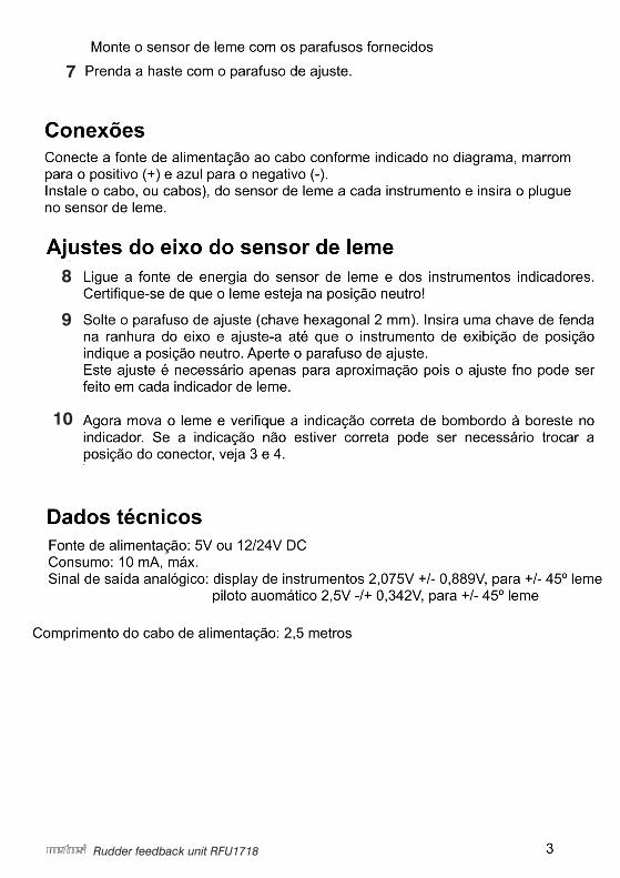
Monte o sensor de leme com os parafusos fornecidos
Salvatore A Italiano
Conexões
Salvatore A Italiano
Prenda a haste com o parafuso de ajuste.
Salvatore A Italiano
Conecte a fonte de alimentação ao cabo conforme indicado no diagrama, marrom para o positivo (+) e azul para o negativo (-).Instale o cabo, ou cabos), do sensor de leme a cada instrumento e insira o plugue no sensor de leme.
Salvatore A Italiano
Ajustes do eixo do sensor de leme
Salvatore A Italiano
Ligue a fonte de energia do sensor de leme e dos instrumentos indicadores. Certifique-se de que o leme esteja na posição neutro!
Salvatore A Italiano
Solte o parafuso de ajuste (chave hexagonal 2 mm). Insira uma chave de fenda na ranhura do eixo e ajuste-a até que o instrumento de exibição de posição indique a posição neutro. Aperte o parafuso de ajuste.Este ajuste é necessário apenas para aproximação pois o ajuste fno pode ser feito em cada indicador de leme.
Salvatore A Italiano
Agora mova o leme e verifique a indicação correta de bombordo à boreste no indicador. Se a indicação não estiver correta pode ser necessário trocar a posição do conector, veja 3 e 4.
Salvatore A Italiano
Dados técnicos
Salvatore A Italiano
Fonte de alimentação: 5V ou 12/24V DCConsumo: 10 mA, máx.Sinal de saída analógico: display de instrumentos 2,075V +/- 0,889V, para +/- 45º leme piloto auomático 2,5V -/+ 0,342V, para +/- 45º leme
Salvatore A Italiano
Comprimento do cabo de alimentação: 2,5 metros
Salvatore A Italiano
Salvatore A Italiano
3
14 100206.04 Rudder feedback unit RFU1718
Hoofdafmetingen Overall dimensions HauptmaßeDimensions pricipales Dimensions pricipales Misure pricipali
1 Roerstandgever 2 Uitgang voor afleesin- strument 3 Uitgang voor autopiloot AP2S 4 Aan/uit schakelaar 5 Zekering 500 mA 6 Accu
Kleurcode bedrading:AP2S Roerstandgever 11 Rood + Bruin 12 Blauw - Blauw 13 Groen Uitgang AP2S
1 Rudder feedback unit 2 Output for display instru- ment 3 Output for autopilot AP2S 4 On/off switch 5 Fuse 500 mA 6 Battery
Wiring colour code:AP2S Rudder feedback unit 11 Red + Brown 12 Blue - Blue 13 Green Output AP2S
1 Ruderstandmesser 2 Ausgang des Anzeigeinstruments 3 Ausgang des Autopiloten AP2S 4 Ein-Aus-Schalter 5 Sicherung 500 mA 6 Batterie
Farbkode Bekabelung:AP2S Ruderstandmesser 11 Rot + Braun 12 Blau - Blau 13 Grün Ausgang AP2S
Salvatore A Italiano
Salvatore A Italiano
Salvatore A Italiano
Salvatore A Italiano
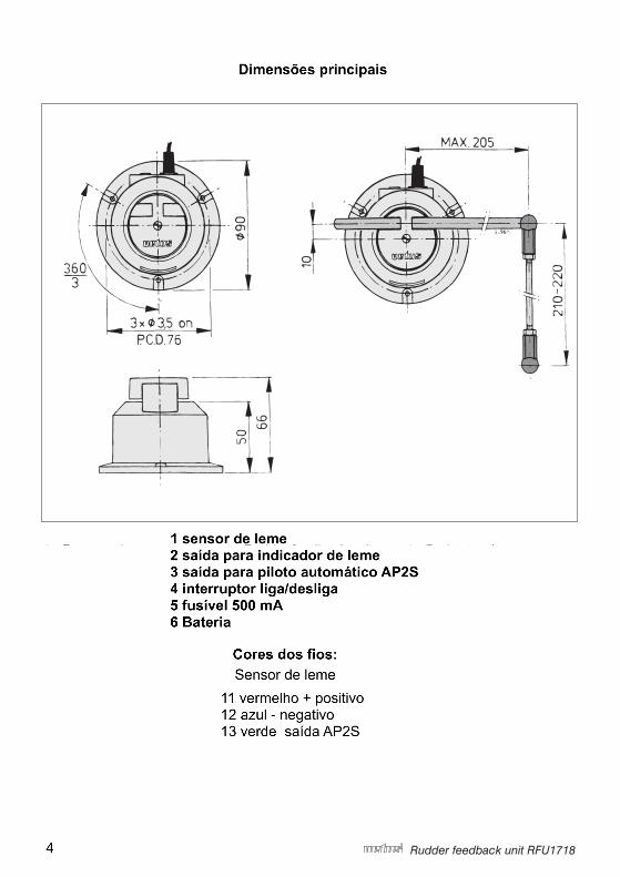
Dimensões principais
Salvatore A Italiano
1 sensor de leme2 saída para indicador de leme3 saída para piloto automático AP2S4 interruptor liga/desliga5 fusível 500 mA6 Bateria
Salvatore A Italiano
Cores dos fios:
Salvatore A Italiano
Sensor de leme
Salvatore A Italiano
11 vermelho + positivo 12 azul - negativo13 verde saída AP2S
Salvatore A Italiano
4
100206.04 15Rudder feedback unit RFU1718
Aansluitschema Wiring diagram AnschlußschemaSchémas électriques Esquema de conexión Schema dei collega- menti
1 Indicateur de position du gouvernail
2 Sortie pour instrument à cadran
3 Sortie pour pilote auto-matique (AP2S)
4 Interrupteur Marche/Arrêt 5 Fusible 500 mA 6 Batterie
Code de couleurs pour lecâblage AP2S Indicateur de positiondu gouvernail 11 Rouge + Brun 12 Bleu - Bleu 13 Vert Sortie AP2S
1 Unidad de reacción del timón
2 Salida para instrumento de lectura
3 Salida para piloto elec-trónico AP2S
4 Interruptor para activar-desactivar
5 Fusible 500 mA 6 Batería
Códigos de color cableado:
AP2S Unidad de reacción del timón 11 Rojo + Marrón 12 Azul - Azul 13 Verde Salida AP2S
1 Indicatore di tacco del timone
2 Uscita per strumento di lettura
3 Uscita per autopilota AP2S
4 Commutatore acceso/spento
5 Valvola a 500 mA 6 Batteria
Codice cromatico dei filielettrici:AP2S Indicatore di tacco 11 Rosso + Marrone 12 Blu - Blu 13 Verde Uscita AP2S
Salvatore A Italiano
Salvatore A Italiano
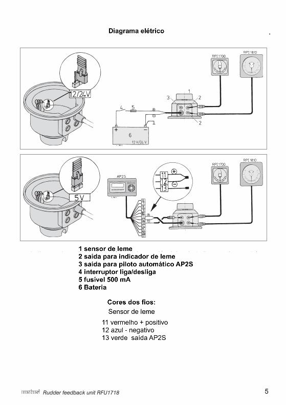
Diagrama elétrico
Salvatore A Italiano
Salvatore A Italiano
1 sensor de leme2 saída para indicador de leme3 saída para piloto automático AP2S4 interruptor liga/desliga5 fusível 500 mA6 Bateria
Salvatore A Italiano
Cores dos fios:
Salvatore A Italiano
Sensor de leme
Salvatore A Italiano
11 vermelho + positivo 12 azul - negativo13 verde saída AP2S
Salvatore A Italiano
5
16 100206.04 Rudder feedback unit RFU1718
1 2
3
4
RPI1800
RPI1700RPI1810
AP2S
GroenGreenGrünVert
VerdeVerde
GroenGreenGrünVertVerdeVerde
Salvatore A Italiano
Salvatore A Italiano
Salvatore A Italiano
verde
Salvatore A Italiano
verde
Salvatore A Italiano
6
100206.04 17Rudder feedback unit RFU1718
5
6 7
8
9 10
Salvatore A Italiano
7

TERMO DE GARANTIA LIMITADA DE ACESSÓRIOS E PEÇAS PARA REPOSIÇÃO
I - PRAZO E COMPROVAÇÃO DA GARANTIA 1. Os acessórios e peças de reposição comercializados pela Marine Office são garantidos pelos seguintes prazos: - Acessórios e Peças de reposição são cobertas por um período de 90 (noventa) dias a partir da emissão da nota fiscal. 2. Para a comprovação deste prazo, o consumidor deverá apresentar a 1ª via da nota fiscal de compra. II – ABRANGÊNCIA DA GARANTIA 1. Esta garantia contratual é dada ao produto, exclusivamente contra eventuais defeitos decorrentes de fabricação, montagem executada pelo fabricante, ou quaisquer outros vícios de qualidade que o tornem impróprio ou inadequado ao uso regular. III - EXCLUSÃO DE GARANTIA A garantia não abrange: a) os danos sofridos pelo produto, ou seus acessórios, em consequência de acidente, mau uso, manuseio ou operação incorreta e inadequada; b) os danos sofridos pelo produto devido a montagem em desacordo com o manual de instalação. IV - LOCAL ONDE A GARANTIA DEVERÁ SER EFETUADA 1. Os consertos em garantia somente deverão ser efetuados por um distribuidor, devidamente nomeado pela Marine Office, que, para tanto, se utilizará de técnicos especializados e de peças originais, garantindo o serviço executado. 2. O ônus pelo transporte do produto até o distribuidor, independentemente do motivo, será arcado pelo cliente. V - CESSAÇÃO DA GARANTIA 1. Não confie o conserto do produto a curiosos, pessoas ou oficinas não autorizadas e não credenciadas pela Marine Office, se isto vier a ocorrer a garantia cessará, de imediato. 2. Os acessórios e peças de reposição são projetados para funcionamento e uso específico para uma atividade, única e exclusivamente. A sua utilização, para uso além de sua capacidade ou especificação, acarretará o imediato cancelamento da garantia. VI - RECOMENDAÇÕES ESPECIAIS 1. Antes de colocar o produto em funcionamento, leia atentamente as instruções de uso e/ou instalação contidas no próprio aparelho, na embalagem, ou no manual respectivo. Siga-as rigorosamente. Elas são a sua segurança. 2. Certifique-se de que a tensão a ser utilizada é a mesma indicada no aparelho. Verifique se a instalação elétrica do local está correta em perfeito estado. 3. Não introduza quaisquer objetos estranhos à função própria do produto, principalmente quando este estiver em funcionamento, evitando acidentes. VII - IMPORTADOR MARINE OFFICE C.I.E.R.C. Ltda. ASSISTÊNCIA TÉCNICA AUTORIZADA SÃO PAULO – SP Rua Anhaia, 982 – Bom Retiro Cep: 01130-000 Telefone: (11) 3477-5655 Site: www.marineoffice.com.br
Salvatore A Italiano
Salvatore A Italiano
Salvatore A Italiano
Salvatore A Italiano
Salvatore A Italiano