Aula 8 - Unidade lógica aritmética e Multiplicadores · I Circuito digital (pode ser...
18
Aula 8 - Unidade lógica aritmética e Multiplicadores Prof. Renan Sebem Disciplina de Eletrônica Digital Graduação em Engenharia Elétrica Universidade do Estado de Santa Catarina Joinville-SC – Brasil 15 de março de 2016 ELD0001 ‡ Prof. Renan Sebem ‡ Aula 8 1 / 17
-
Upload
trinhkhanh -
Category
Documents
-
view
221 -
download
0
Transcript of Aula 8 - Unidade lógica aritmética e Multiplicadores · I Circuito digital (pode ser...
Aula 8 - Unidade lógica aritmética eMultiplicadores
Prof. Renan Sebem
Disciplina de Eletrônica DigitalGraduação em Engenharia Elétrica
Universidade do Estado de Santa CatarinaJoinville-SC – Brasil
15 de março de 2016
ELD0001 ‡ Prof. Renan Sebem ‡ Aula 8 1 / 17
Conteúdo da Aula
Avisos
Trabalho
Somador serial
Unidade lógica aritmética
Multiplicadores
Sobre a prova
Bibliografia
ELD0001 ‡ Prof. Renan Sebem ‡ Aula 8 2 / 17
Avisos
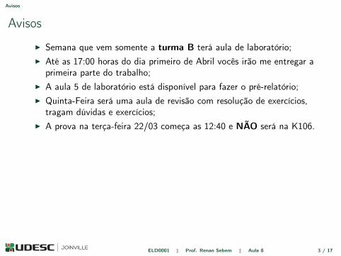
Avisos
I Semana que vem somente a turma B terá aula de laboratório;I Até as 17:00 horas do dia primeiro de Abril vocês irão me entregar a
primeira parte do trabalho;I A aula 5 de laboratório está disponível para fazer o pré-relatório;I Quinta-Feira será uma aula de revisão com resolução de exercícios,
tragam dúvidas e exercícios;I A prova na terça-feira 22/03 começa as 12:40 e NÃO será na K106.
ELD0001 ‡ Prof. Renan Sebem ‡ Aula 8 3 / 17
Trabalho
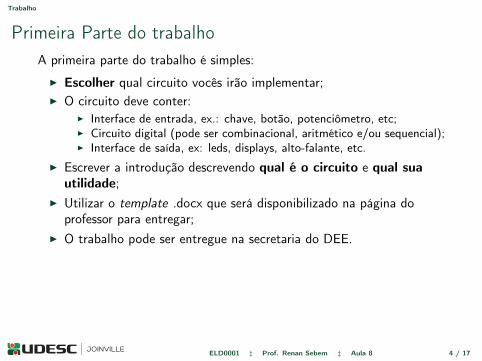
Primeira Parte do trabalhoA primeira parte do trabalho é simples:
I Escolher qual circuito vocês irão implementar;I O circuito deve conter:
I Interface de entrada, ex.: chave, botão, potenciômetro, etc;I Circuito digital (pode ser combinacional, aritmético e/ou sequencial);I Interface de saída, ex: leds, displays, alto-falante, etc.
I Escrever a introdução descrevendo qual é o circuito e qual suautilidade;
I Utilizar o template .docx que será disponibilizado na página doprofessor para entregar;
I O trabalho pode ser entregue na secretaria do DEE.
ELD0001 ‡ Prof. Renan Sebem ‡ Aula 8 4 / 17
Somador serial
Somador serial
I O somador serial é um circuito sequêncial e depende de Flip-Flops,por isto será visto na próxima parte da disciplina.
ELD0001 ‡ Prof. Renan Sebem ‡ Aula 8 5 / 17
Unidade lógica aritmética
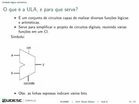
O que é a ULA, e para que serve?I É um conjunto de circuitos capaz de realizar diversas funções lógicas
e aritméticas.I Serve para simplificar o projeto de circuitos digitais, reunindo várias
funções em um CI.Símbolo:
306 CHAPTER 12 Combinational Arithmetic Circuits
12.8 Arithmetic-Logic UnitA typical arithmetic-logic unit (ALU) symbol is shown in Figure 12.17. It contains two main inputs (a, b) plus an operation-select port (opcode) and a main output (y). The circuit performs general logical (AND, OR, etc.) and arithmetic (addition, subtraction, etc.) operations, selected by opcode. To construct it, a com-bination of circuits is employed, particularly logic gates, adders, decoders, and multiplexers.
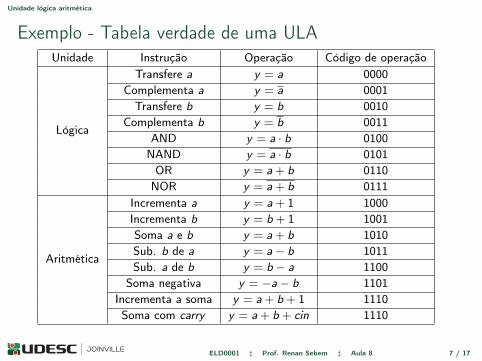
An example of ALU specifi cations is included in Figure 12.17. In this case, opcode contains 4 bits, so up to 16 operations can be selected. In the upper part of the table, eight logical operations are listed involving inputs a and b, either individually or collectively. Likewise, in the lower part of the table, eight arithmetic operations are listed, involving again a and b, either individually or collectively; in one of them, cin is also included. Note that the MSB of opcode is responsible for selecting whether the logic (for '0') or arithmetic (for '1') result should be sent out.
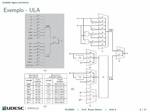
The construction of an ALU is depicted in Figure 12.18, which implements the functionalities listed in Figure 12.17. In Figure 12.18(a), a conceptual circuit is shown, which serves as a reference for the actual design. It contains one multiplexer in each section (logic at the top, arithmetic at the bottom), connected to an output multiplexer that selects one of them to be actually connected to y.
Circuit details are shown in Figure 12.18(b). Thick lines were employed to emphasize the fact that ALUs are normally multibit circuits. The upper (logic) section is a straight implementation of the equa-tions listed in the specifi cations of Figure 12.17 with all gates preceding the multiplexer. The arithmetic section, however, was designed differently. Due to the adder’s large circuit (seen in Sections 12.2–12.3), it is important not to repeat it, so the multiplexers were placed before the adder. This, on the other hand, causes the instruction decoder, which takes opcode and converts it into commands for the switches (mul-tiplexers), to be more complex.
The fi gure also shows that a and b can be connected to the adder directly or through a two’s complementer (for subtraction, as discussed in Section 12.5). Note that the multiplexers also have an input equal to zero (an actual adder must not operate with inputs fl oating) and that multiplexer D is a single-bit mux.
Finally, the specifi cations for the instruction decoder are listed in Figure 12.18(c), showing which switches (multiplexer sections) should be closed in each case. This circuit can be designed using the
FIGURE 12.17. ALU symbol and ALU specifi cations example.
I Obs: as linhas espessas indicam vários bits.
ELD0001 ‡ Prof. Renan Sebem ‡ Aula 8 6 / 17
Unidade lógica aritmética
Exemplo - Tabela verdade de uma ULAUnidade Instrução Operação Código de operação
Lógica
Transfere a y = a 0000Complementa a y = a 0001
Transfere b y = b 0010Complementa b y = b 0011
AND y = a · b 0100NAND y = a · b 0101
OR y = a+ b 0110NOR y = a+ b 0111
Aritmética
Incrementa a y = a+ 1 1000Incrementa b y = b + 1 1001Soma a e b y = a+ b 1010Sub. b de a y = a− b 1011Sub. a de b y = b − a 1100
Soma negativa y = −a− b 1101Incrementa a soma y = a+ b + 1 1110Soma com carry y = a+ b + cin 1110
ELD0001 ‡ Prof. Renan Sebem ‡ Aula 8 7 / 17
Unidade lógica aritmética
Exemplo - ULA
procedure presented in Section 11.5 (as in Example 11.4). Note that the MSB of opcode can be connected directly to multiplexer E.
12.9 MultipliersBinary multiplication was discussed in Sections 3.4–3.5. The traditional multiplication algorithm of Figure 3.8(a) was repeated in Figure 12.19. The inputs are a = a3a2a1a0 (multiplier) and b = b3b2b1b0 (mul-tiplicand), while the output is p = p7 . . . p1p0 (product). For N-bit inputs, the output must be 2N bits wide to prevent overfl ow. Because the multiplication algorithm involves logical multiplication plus arithmetic addition, AND gates plus full-adder units, respectively, can be used to implement it.
12.9 Multipliers 307
FIGURE 12.18. Circuit for the ALU specifi ed in Figure 12.17: (a) Conceptual circuit; (b) Construction example; (c) Specifi cations for the instruction decoder.
ELD0001 ‡ Prof. Renan Sebem ‡ Aula 8 8 / 17
Unidade lógica aritmética
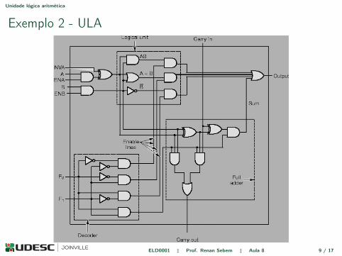
Exemplo 2 - ULA
ELD0001 ‡ Prof. Renan Sebem ‡ Aula 8 9 / 17
Unidade lógica aritmética
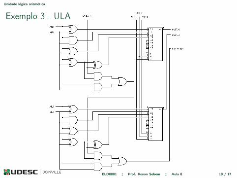
Exemplo 3 - ULA
ELD0001 ‡ Prof. Renan Sebem ‡ Aula 8 10 / 17
Multiplicadores
Porquê estudar multiplicadores?
I As operações mais importantes e mais utilizadas em um processadordigital de sinais (DSP - digital signal processor) são as demultiplicação e soma;
I Conhecidas como MAC - multiply-accumulate operation.
ELD0001 ‡ Prof. Renan Sebem ‡ Aula 8 11 / 17
Multiplicadores
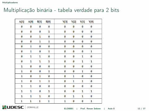
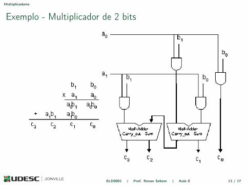
Multiplicação binária - tabela verdade para 2 bits
ELD0001 ‡ Prof. Renan Sebem ‡ Aula 8 12 / 17
Multiplicadores
Exemplo - Multiplicador de 2 bits
ELD0001 ‡ Prof. Renan Sebem ‡ Aula 8 13 / 17
Multiplicadores
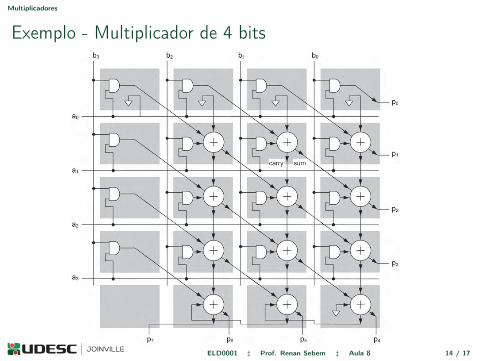
Exemplo - Multiplicador de 4 bits
308 CHAPTER 12 Combinational Arithmetic Circuits
12.9.1 Parallel Unsigned MultiplierA parallel-input parallel-output circuit (also known as array multiplier) that performs the operations depicted in Figure 12.19 is shown in Figure 12.20. The circuit is combinational because its output depends only on its current inputs. As expected, it employs an array of AND gates plus full-adder units. Indeed, p0 = a0b0, p1 = a0b1 + a1b0, p2 = a0b2 + a1b1 + a2b0 + carry(p1), etc. This circuit operates only with positive (unsigned) inputs, also producing a positive (unsigned) output.
FIGURE 12.20. Parallel-input parallel-output unsigned multiplier.
FIGURE 12.19. Traditional unsigned multiplication algorithm.
ELD0001 ‡ Prof. Renan Sebem ‡ Aula 8 14 / 17
Sobre a prova
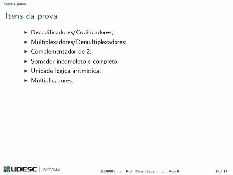
Itens da prova
I Decodificadores/Codificadores;I Multiplexadores/Demultiplexadores;I Complementador de 2;I Somador incompleto e completo;I Unidade lógica aritmética;I Multiplicadores.
ELD0001 ‡ Prof. Renan Sebem ‡ Aula 8 15 / 17

Avisos
Avisos
I Semana que vem somente a turma B terá aula de laboratório;I Até as 17:00 horas do dia primeiro de Abril vocês irão me entregar a
primeira parte do trabalho;I A aula 5 de laboratório está disponível para fazer o pré-relatório;I Quinta-Feira será uma aula de revisão com resolução de exercícios,
tragam dúvidas e exercícios;I A prova na terça-feira 22/03 começa as 12:40 e NÃO será na K106.
ELD0001 ‡ Prof. Renan Sebem ‡ Aula 8 16 / 17

Bibliografia
[1] Volnei A. Pedroni. Eletrônica digital moderna e VHDL: Princípiosdigitais, Eletrônica Digital, Projeto Digital, Microeletrônica e VHDL.Elsevier, 2010.
ELD0001 ‡ Prof. Renan Sebem ‡ Aula 8 17 / 17
Aula 8 - Unidade lógica aritmética eMultiplicadores
Prof. Renan Sebem
Disciplina de Eletrônica DigitalGraduação em Engenharia Elétrica
Universidade do Estado de Santa CatarinaJoinville-SC – Brasil
15 de março de 2016
Obrigado.
ELD0001 ‡ Prof. Renan Sebem ‡ Aula 8 18 / 17


![Lec8[1]Multiplicadores de Lagrange](https://static.fdocumentos.com/doc/165x107/577cd5521a28ab9e789a79ff/lec81multiplicadores-de-lagrange.jpg)