s r e t il F SFB os r t il F -...
16
F il t ros - F il t e rs 13 SÉRIE SFB SERIES Filtro de Aspiração Suction filters
-
Upload
truongduong -
Category
Documents
-
view
213 -
download
0
Transcript of s r e t il F SFB os r t il F -...

Filtr
os
- F
ilte
rs
13
SÉRIE SFB SERIES
Filtro de Aspiração Suction filters

DESCRIÇÃO
DESCRIPTION
Os filtros da nossa gama SFB são adaptáveis para a
utilização em linhas de aspiração para bombas externas,
com fluxo a 900 l/min.
Flangeado na lateral do depósito, debaixo do nível do
óleo, a sua perda de pressão é mantida ao nível minímo.
Estão equipados com um mecanismo de fecho particular,
o elemento pode ser modificado sem desvaziar o tanque.
Estes filtros são equipados com um veio magnético
desenhado para capturar as partículas metálicas, eles
não serão fornecidos com válvula by-pass.
Um indicador elétrico para o sinal de posição de fecho na
entrada e porte elétrico com pressão indicada disponível.
A instalação e manutenção destes filtros não são um
problema, e os depósitos de uma vasta permitem a
utilização destes filtros em várias aplicações.
Os filtros da série SFB foram manufacturados e testados
de acordo com as seguintes normas ISO:
ISO 2941 Óleohidráulica - Elemento filtrante - Verifica a
resistência/colapso;
ISO 2943 Óleohidráulica – Elemento filtrante – Verifica a
compatibilidade com fluído
ISO 3723 Óleohidráulica - Elemento filtrante - Verifica a
resistência do processo;
ISO 3724 Óleohidráulica – Elemento filtrante – Verifica o
fluxo e características da fadiga.
ISO 3968 Óleohidráulica - Filtro – Determinação da
avaliação de pressão vs as características de fluxo.
The filters of our SFB series are suitable for use in suction
lines of external pumps, with flow rates up to 900 l/min.
Flanged to the tank side underneath the oil level, their pres-
sure loss is maintained at a minimal level.
They are equippeded with a particular closing mechanism,
the element can be exchanged without having to empty the
tank.
As these filters are equipped with an magnetic shaft designed
to capture metallic contaminant particles, they will not be
supplied with a by-pass valve.
An electrical indicator for the signalling of the closed position
of the inlet port and an electrical clogging indicator with
settable pressure are available.
Installation and maintenance of these filters is unproblematic,
and thanks to the vast range of the available filtration media
these filters can be used in many different applications.
SFB series is manufactured and tested according to the
following ISO standards:
ISO 2941 Hydraulic fluid power - Filter elements - Verification
of collapse/burst pressure resistance;
ISO 2943 Hydraulic fluid power - Filter elements - Verification
of material compatibility with fluid;
ISO 3723 Hydraulic fluid power - Filter elements - Method
for end load tests;
ISO 3724 Hydraulic fluid power - Filter elements - Verification
of flow fatigue characteristics;
ISO 3968 Hydraulic fluid power - Filters - Evaluation of pres-
sure drop versus flow characteristics.
De forma a constantemente melhorar a qualidade dos nossos produtos, tomamos as medidas necessárias
nos catálogos para a sua modificação sem notícia.
Os clientes tem a responsabildiade de continuadamente verificar as alterações dos catálogos. Este catálogo
cancela o anterior.
In order to constantly improve our products quality, we take the right to make changes to the catalogues at any
time without notice.
Customers have the responsibility to continuously check all the information in the catalogues.
This catalogue cancels and replaces the previous ones.
Versão - Version 01/022009

CARACTERÍSTICAS TÉCNICAS
TECHNICAL DATA
1
MATERIAIS DE CONSTRUÇÃO
Corpo filtro
Tubo Alumínio
SFB 535 e SFB 540 aço
Vedantes Buna-N o Vitão (opcional)
Tratamento Tubo Anodização
Elemento Filtrante
Material Filtrante Mistura de metal
Suporte Aço galvazinado com
tratamento
Tubo interno Aço zincato
Cobertura Aço zincato
COMPATIBILIDADE FLUÍDO A série SFB é compatível com óleos minerais de tipo HH
– HM – HR – HV – HG de acordo com ISO 6743/4 para
uma temperatura de -20°C e +95°C. Para qualquer outra
aplicação por favor contacte o Departamento de Vendas.
PRESSÃO
Elemento Filtrante
Pressão de Colapso 3 bar
INDICADORES DE TRABALHO
Vácuo
VE2 Material: corpo em
Alumínio
Iniciação: – 0,2 bar ±10%
Contacto: dupla mudança;
Conexão Faston
Vmax: 250 Vac
Conexões: 1/4” BSP
CONSTRUCTION MATERIALS
Filter housing
Housing Aluminium alloy
SFB 535 and SFB 540 steel
Seals Buna-N or Viton (optional)
Housing treatment Anodizing
Filter elements
Filter media Steel wire mesh
Support wire mesh Galvanized steel with epoxy treat-
ment
Internal core Zinc treated steel
End caps Zinc treated steel
FLUID COMPATIBILITY
SFB series is compatible with mineral oils type HH - HM -
HR - HV - HG according to ISO 6743/4, for temperature
range between -20°C and +95°C.
For any other application please contact the OMT S.p.A.
Sales Department.
PRESSURE
Filter elements
Collapse rating 3 bar
CLOGGING INDICATORS
Vacuum switch
VE2 Construction
materials: body anodized Aluminium
Setting: – 0,2 bar ±10%
Switch: double switch;
connection Faston
Vmax: 250 Vac
Connection: 1/4” BSP
Vacómetro
VV2 Material Aço
Gama 0 - - 76 cmHg Conexão: 1/4” BSP axial- Ø 63 mm
Vacuometer
VE3 Material:
Iniciação:
Corpo em Aço
– 0,2 bar ±10%
VE3
Construction
Contacto Mudança materials: body anodized Aluminium
Dupla Mudança DIN 43650
Setting: – 0,2 bar ±10%
Vmax:
Conexão:
250 Vac 1/4” BSP
Switch:
Vmax:
double switch;
connection DIN 43650
250 Vac
Connection: 1/4” BSP
VV2 Construction
materials:
Steel
Range:
Connection:
0 - - 76 cmHg
axial 1/4” BSP - Ø 63 mm

2
Graus de Filtração
Filtration degrees
A atenção particular da nossa empresa que sempre se
dedicou á escolha da excelente filtração nos nossos
filtros, permite ao Departamento de Desenvolvimento
desenvolver elementos filtráveis que se adaptam à
maioria das aplicações com uma alta taxa de filtração e
elevado nível de limpeza que previne a contaminação.
O rácio de filtração é definido pelo diâmetro da mais larga
partícula esférica.
The particular attention our company has always dedicated
to the choice of the filtration media used in our filters has
allowed our R&D department to develop filtration elements
suitable even for the most demanding applications, with a
high filtration efficiency and an elevated dirt holding capaci-
ty of solid contaminant.
The filtration rating is defined by the diameter of the largest
hard spherical particle that will pass the media.
GRAU DA FILTRAÇÃO / FILTRATION DEGREE
Código
Code
Grau da Filtração Filtration degree
[m]
Tipo Type Tipo de material
Wire material
C 60 REPS Aço / Steel AISI304
E 125 Quadrado / Square mesh Aço / Steel AISI304
R 250 Quadrado / Square mesh Aço / Steel AISI304
U 90 Quadrado / Square mesh Aço / Steel AISI304
Z 25 Quadrado / Square mesh Aço /Steel AISI304
SUPERFÍCIE FILTRANTE / FILTRATION AREA
SFBR
505
510
503
504
535
540
cm2
1730
1820
2300
2680
3670
5130
Os elementos de filtração SFBR não modificam os graus
de filtração.
The SFBR elements filtration area does not change with the
filtration degrees.

3
Queda de Pressão
Pressure drops
4
A queda de pressão dos filtros completos é calculado
pela adesão da pressão do tubo ao elemento filtrante,
referindo o rácio do fluxo.
A pressão do tubo é proporcional ás variações da
densidade da massa do fluído.
O elemento do filtro da queda da pressão é proporcional
ás variações da viscosidade do fluído.
Escolha o seu filtro SFB para completar a queda da pressão do filtro limpo, calculando o fluxo de trabalho, é menos do que 0,1 bar.
A curva de pressão no seguinte gráfico é do óleo
mineral 3 com densidade de 860 kg/m3 e viscosidade
de 30 cSt .
Nota: 1 bar = 105 Pa; 1 cSt = 1 mm2/sec.
The pressure drop of the complete filters is calculated by
adding the housing pressure drop to that of the filter ele-
ment, referred to the working flow rate.
The housing pressure drop is proportional to the variations
of the fluid mass density.
The filter element pressure drop is proportional to the varia-
tions of the fluid kinematic viscosity.
Select your SFB filter so that the complete pressure drop of
the clean filter, calculated at the working flow rate, is less
than 0,1 bar.
Pressure curves of the following graphs are for mineral
oil 3 with density of 860 kg/m3 and kinematic viscosity
of 30 cSt.
Note: 1 bar = 105 Pa; 1 cSt = 1 mm2/sec.
QUEDA DE PRESSÃO TUBO / HOUSING PRESSURE DROPS
0,1
0,09
0,08
0,07
0,06
0,05
0,04
0,03
0,02
0,01
0
0 100 200 300 400 500 600 700 800 900
Fluxo / Flow rate [l/min]
4” 3”
2 1 /2”
2”
De
lta
P [
KP
a]

4
Queda de Pressão
Pressure drops
QUEDA DE PRESSÃO ELEMENTO FILTRANTE / FILTER ELEMENT PRESSURE DROPS
5
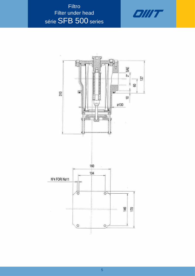
Filtro
Filter under head
série SFB 500 series

6
Filtro
Filter under head
série SFB 501 series
7
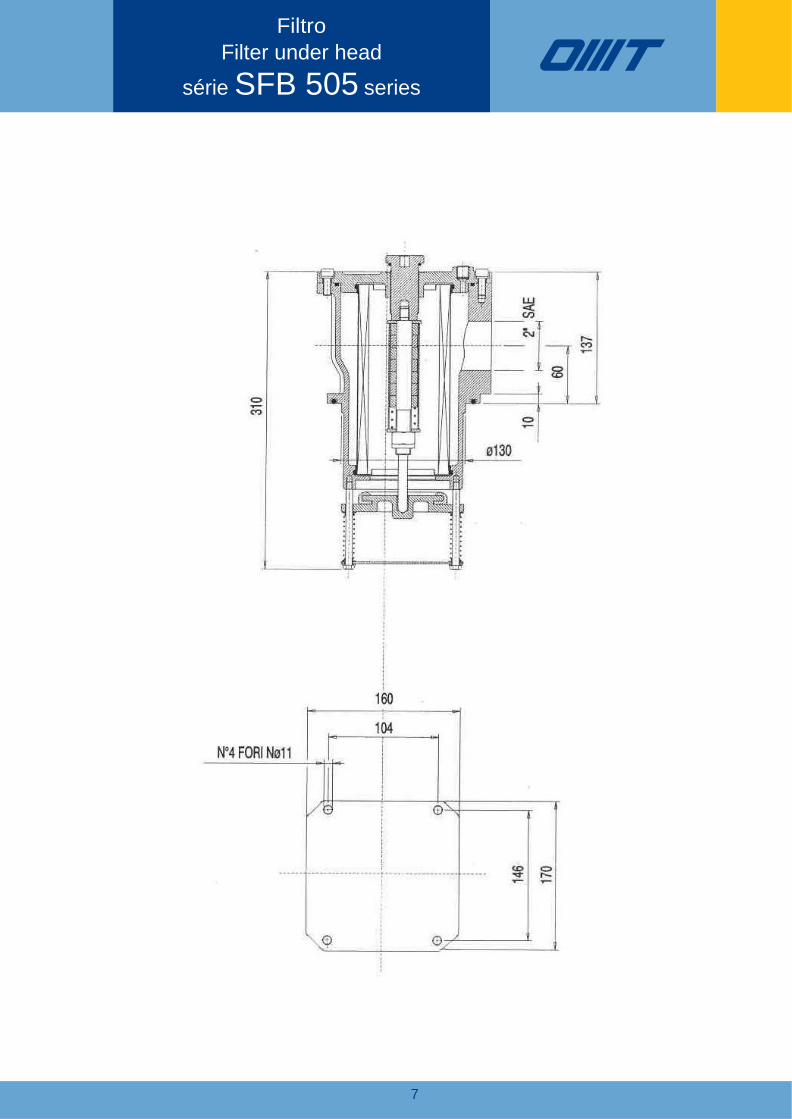
Filtro
Filter under head
série SFB 505 series

8
Filtro
Filter under head
série SFB 510 series

9
Filtro
Filter under head
série SFB 503 series

Filtro
Filter under head
série SFB 504 series
10

11
Filtro
Filter under head
série SFB 535 series
12
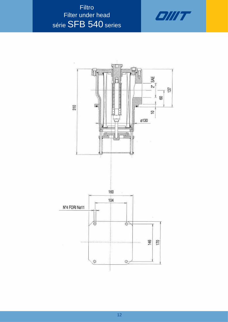
Filtro
Filter under head
série SFB 540 series
13
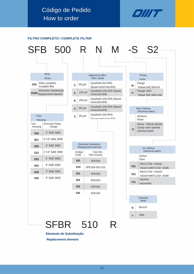
R N M -S S2
Elemento Substituto Replacement element
Código Tubo filtro Code Filter housing
505 SFB 505
510 SFB 500-501-510
503 SFB 503
504 SFB 504
535 SFB 535
540 SFB 540
Vedantes Seals
N Buna N
V Vitão
FILTRO COMPLETO / COMPLETE FILTER
SFB 500
SFB
Série
Series
Filtro completo
Complete filter
Elemento Substituição SFBR Replacement element
SFBR 510 R Elemento de Substituição
Replacement element
Código de Pedido
How to order
Material do filtro
Filter media
C 60 µm Quadrado (Aisi 304)
Square mesh (Aisi 304)
E 125 µm Quadrado (Aisi 304) Square
mesh (Aisi 304)
R 250 µm Quadrado (Aisi 304) Square
mesh (Aisi 304)
U 90 µm Quadrado (Aisi 304) Square
mesh (Aisi 304)
Z 25 µm Quadrado (Aisi 304)
Square mesh (Aisi 304)
Portes
Ports
M
Flange
Flange SAE 3000-M
U Flange UNC
Flange SAE 3000-UNC
Mud. Elétrica
Electrical switch
Nenhuma
None
-S
Abraç. Válvula aberta
Clamp valve opened
electrical switch
Tubo
Housing
Tubo
Housing
Dimensão Flange
Flange
500 2” SAE 3000
501 2 1/2” SAE 3000
505 2” SAE 3000
510 2 1/2” SAE 3000
503 3” SAE 3000
504 4” SAE 3000
535 3” SAE 3000
540 4” SAE 3000
Int. Elétrica
Electrical switch
Nenhum
None
VE2
Vácuo 0,2 bar – contacto
Vacuum switch 0,2 bar - double
switch VE3
Vácuo 0,2 bar – contacto
Vacuum switch 0,2 bar - double
switch VV2
Vacometro
Vacuometer

13
FLANGE / FLANGES
RACOR/ COUPLINGS
BUCHA / MANIFOLDS
COMPONENTES COMPONENTS
ACESSÓRIOS ACCESSORIES
FILTROS
FILTERS
Rec. Calor
HEAT
EXCHANGERS